
Nanostructures DOI: 10.1002/anie.200802248 Shape ...staff.ustc.edu.cn/~yjxiong/paper/Angew-1.pdf ·...
44
Nanostructures DOI: 10.1002/anie.200802248 Shape-Controlled Synthesis of Metal Nanocrystals: Simple Chemistry Meets Complex Physics? Younan Xia,* Yujie Xiong, Byungkwon Lim, and Sara E. Skrabalak Angewandte Chemie Keywords: growth · metal · nanocrystal · nucleation · shape control Y. Xia et al. Reviews 60 www.angewandte.org # 2009 Wiley-VCH Verlag GmbH & Co. KGaA, Weinheim Angew. Chem. Int. Ed. 2009, 48, 60 – 103
Transcript of Nanostructures DOI: 10.1002/anie.200802248 Shape ...staff.ustc.edu.cn/~yjxiong/paper/Angew-1.pdf ·...

NanostructuresDOI: 10.1002/anie.200802248
Shape-Controlled Synthesis of Metal Nanocrystals:Simple Chemistry Meets Complex Physics?Younan Xia,* Yujie Xiong, Byungkwon Lim, and Sara E. Skrabalak
AngewandteChemie
Keywords:growth · metal · nanocrystal · nucleation ·shape control
Y. Xia et al.Reviews
60 www.angewandte.org � 2009 Wiley-VCH Verlag GmbH & Co. KGaA, Weinheim Angew. Chem. Int. Ed. 2009, 48, 60 – 103

1. Introduction
Nanocrystals are crystals with at least one dimensionbetween 1 and 100 nm.[1] They also are characterized by asingle-domain crystalline lattice, without the complicatingpresence of grain boundaries. Interest in nanocrystals hasbeen growing steadily due to their unique position as a bridgebetween atoms and bulk solids as well as their fascinatingproperties and potential applications.[2] The ability to gen-erate such minuscule crystals is central to advances in manyareas of modern science and technology. In principle, theelectron confinement by a nanocrystal provides the mostpowerful means to manipulate the electronic, optical, andmagnetic properties of a solid material. This notion explainswhy nanocrystals have been the primary source for discover-ing and studying quantum size effects, with examples ofquantized excitation,[3] Coulomb blockade,[4] metal–insulatortransition,[5] and superparamagnetism.[6] Among all kinds ofinorganic solids, metals deserve our special attention becausethey represent more than two thirds of the elements in theperiodic table. Most metals crystallize in the same cubic close-packed (ccp) structure, a face-centered cubic (fcc) lattice thatallows easy characterization. Metals also possess a range offascinating properties, and many metals have been applied incatalysis,[7] electronics,[8] photography,[9] and informationstorage,[10] among others.[11] New applications for metals inareas such as photonics,[12] sensing,[13] imaging,[14] and medi-cine[15] are also being developed. Significantly, most of theseapplications require the use of metals in a finely divided state,preferably in the form of nanocrystals with precisely con-trolled properties.
The properties of a metal nanocrystal are determined by aset of physical parameters that may include its size, shape,composition, and structure (e.g., solid or hollow). In principle,
one can tailor and fine-tune the prop-erties of a metal nanocrystal by con-
trolling any one of these parameters, but the flexibility andscope of change are highly sensitive to the specific parameter.For example, in the case of localized surface plasmonresonance (LSPR) and surface-enhanced Raman scattering(SERS), both computational and experimental studies havedemonstrated that the shape and structure of a Au or Agnanocrystal play the most important roles in determining thenumber, position, and intensity of LSPR modes, as well as thespectral region or polarization dependence for effectivemolecular detection by SERS.[16] In the case of catalysis, it iswell-established that the activity of a metal nanocrystal can beenhanced by reducing its size.[17] The selectivity, however, ismost sensitive to the packing of atoms on the surface or theexposed facets of a nanocrystal.[18] For example, Pt canselectively catalyze different types of chemical reactions, withthe {100} and {210} facets being most active for reactionsinvolving H2 and CO, respectively.[19] Of course, the facetsexposed on a nanocrystal have a strong correlation with theshape. These and many other examples clearly illustrate theimportance of shape control to the efficient utilization ofmetal nanocrystals.
The last decade has witnessed the successful synthesis ofmetal nanocrystals in a variety of shapes. Examples include:sphere; spheroid; cube; cuboctahedron; octahedron; tetrahe-
[*] Prof. Y. Xia, Dr. B. LimDepartment of Biomedical Engineering, Washington UniversitySt. Louis, MO 63130-4899 (USA)Fax: (+ 1)314-935-7448E-mail: [email protected]
Dr. Y. Xiong, Dr. S. E. SkrabalakDepartment of Chemistry, University of WashingtonSeattle, WA 98195-1700 (USA)
Nanocrystals are fundamental to modern science and technology.Mastery over the shape of a nanocrystal enables control of its prop-erties and enhancement of its usefulness for a given application. Ouraim is to present a comprehensive review of current research activitiesthat center on the shape-controlled synthesis of metal nanocrystals. Webegin with a brief introduction to nucleation and growth within thecontext of metal nanocrystal synthesis, followed by a discussion of thepossible shapes that a metal nanocrystal might take under differentconditions. We then focus on a variety of experimental parameters thathave been explored to manipulate the nucleation and growth of metalnanocrystals in solution-phase syntheses in an effort to generatespecific shapes. We then elaborate on these approaches by selectingexamples in which there is already reasonable understanding for theobserved shape control or at least the protocols have proven to bereproducible and controllable. Finally, we highlight a number of ap-plications that have been enabled and/or enhanced by the shape-controlled synthesis of metal nanocrystals. We conclude this articlewith personal perspectives on the directions toward which futureresearch in this field might take.
From the Contents
1. Introduction 61
2. Nucleation: The Birth of a NewPhase 63
3. Evolution from Nuclei to Seeds 66
4. Evolution from Seeds toNanocrystals 69
5. Case Studies of Different Metals 74
6. Stability of the Shape 88
7. Properties and ApplicationsEnabled by Shape-ControlledSynthesis 89
8. Summary and Outlook 95
Metal NanocrystalsAngewandte
Chemie
61Angew. Chem. Int. Ed. 2009, 48, 60 – 103 � 2009 Wiley-VCH Verlag GmbH & Co. KGaA, Weinheim

dron; right bipyramid; decahedron; icosahedron; thin platewith a triangular, hexagonal, or circular profile; and rod orwire with a circular, square, rectangular, pentagonal, oroctagonal cross-section. As limited by space, we restrictourselves to solution-phase methods of preparation in thisReview. According to Wulff�s theorem (or the Wulff con-struction),[20] a single crystal of an fcc metal assumes the so-called Wulff polyhedron (a truncated octahedron) as itsequilibrium shape in an inert gas or vacuum (strictly speaking,this result is only valid at 0 K). This prediction has beenexperimentally validated for a number of metals.[21] In asolution phase, however, the product often adopts a shapedrastically different from the Wulff polyhedron. This devia-tion can be attributed to a number of scenarios that mayinclude: 1) the equilibrium condition never being reachedduring synthesis; 2) the surface energies for various facetsbeing different from those in a vacuum due to anisotropicinteractions with a capping agent, impurity, or solvent; 3) twindefects being included during nucleation and growth to formshapes such as decahedron and icosahedron with a total freeenergy lower than that of the Wulff polyhedron; and4) applying an elevated temperature for the synthesis. Forthese reasons, it is not hard to understand why solution-phasesyntheses are inherently more powerful and versatile (at thesame time, more complicated) than vapor-phase methods forgenerating metal nanocrystals of different shapes.
The first documented solution-phase synthesis of metalnanoparticles can be traced back to the 1850�s when Michael
Faraday prepared his now famous Au colloids by reducinggold chloride with phosphorus in water.[22] Over the past 150years, a myriad of solution-phase methods have beendeveloped for preparing metal colloids; however, most ofthe samples were troubled by problems such as polydispersedsizes, poorly defined shapes, and limited morphologies. Onlywithin the last decade have solution-phase methods bloss-omed and become a powerful approach toward preparingmetal nanocrystals with the quality, quantity, and reproduci-bility suitable for a meaningful study of their shape–propertyrelationships. As a result, most of the references cited in thisReview were published after 2000. For earlier work on metalnanoparticles, please refer to a number of nice review articlespublished in the 80�s and 90�s.[23] In addition, we focus only onthose systems (see Table 1) where there is already somereasonable understanding for the observed shape control or atleast the synthetic protocols have proven to be reproducibleand controllable.
Compared to organic synthesis where a virtually endlessnumber of molecules with complex structures and functions(e.g., fluorescent dyes or drugs) can be designed andsynthesized, controlling the assembly of metal atoms intonanocrystals is still at a rudimentary stage. Interestingly, thechemical reactions involved in syntheses of metal nanocrys-tals often appear to be fairly simple, and most of them can bereadily found in chemistry textbooks. It is the nucleation andgrowth mechanisms behind the simple chemistry that isextremely complicated. In fact, scientists have just begun to
Younan Xia was born in Jiangsu, China, in1965. He studied chemical physics at theUniversity of Science and Technology ofChina (B.S. 1987) and inorganic chemistryat the University of Pennsylvania with Prof.A. G. MacDiarmid (M.S. 1993). He receiveda Ph.D. degree in physical chemistry fromHarvard University (with Professor GeorgeM. Whitesides) in 1996 and started as anAssistant Professor of Chemistry at the Uni-versity of Washington in Seattle in 1997. Hewas promoted to Associate Professor andProfessor in 2002 and 2004, respectively. In
2007, he relocated to Washington University in St. Louis to take theposition of James M. McKelvey Professor for Advanced Materials in theDepartment of Biomedical Engineering.
Yujie Xiong was born in Jiangxi, China, in1979. He studied chemical physics at theUniversity of Science and Technology ofChina (B.S. 2000) and received a Ph.D.degree in inorganic chemistry under thetutelage of Prof. Yi Xie in 2004 (BestDoctoral Dissertation Award from the Chi-nese Academy of Sciences). From 2004 to2007, he worked as a postdoctoral fellowwith Prof. Younan Xia at the University ofWashington in Seattle, where his researchcentered on shape-controlled synthesis ofnoble-metal nanocrystals. He is currently
working on energy-saving devices with Prof. J. A. Rogers at the University ofIllinois at Urbana-Champaign.
Byungkwon Lim was born in Seoul, Korea,in 1975. He received his B.S. (1998), M.S.(2000), and Ph.D. (2004) degrees all fromthe School of Chemical and Biological Engi-neering at Seoul National University. Duringhis graduate study, he worked on the syn-thesis of polymeric and carboneous nano-structures using vapor deposition polymeri-zation. He then worked as a seniorresearcher for 3 years at LG Chem, Korea.He has been working with Prof. Younan Xiaas a postdoctoral fellow since 2007. Hisresearch interests include shape-controlled
synthesis of noble-metal nanocrystals, surface plasmonic properties, andcarboneous nanostructures.
Sara E. Skrabalak received a B.A. degree inchemistry from Washington University in St.Louis with Prof. W. E. Buhro and a Ph.D.degree from the University of Illinois atUrbana-Champaign under the tutelage ofProf. K. S. Suslick. She was the recipient ofthe 2002 Sowden Award and the 2006 T. S.Piper Thesis Research Award. She has beenworking with Prof. Younan Xia as a postdoc-toral fellow since 2007 and started as anAssistant Professor of Chemistry at IndianaUniversity in Bloomington in fall 2008. Herresearch interests include shape controlledsynthesis of inorganic solids, solar energyconversion, catalysis, and nanotechnology.
Y. Xia et al.Reviews
62 www.angewandte.org � 2009 Wiley-VCH Verlag GmbH & Co. KGaA, Weinheim Angew. Chem. Int. Ed. 2009, 48, 60 – 103

understand the complex physics that lead to the formation ofnanocrystals with specific shapes. At the current stage ofdevelopment, it is not an exaggeration to say that thechemical synthesis of metal nanocrystals (as well as forother solid materials) remains an art rather than a science. Itmust be emphasized that our current understanding of thesesyntheses is far from being able to present atomistic details forthe evolution pathways that a precursor compound may taketo form metal atoms, nuclei, and then well-defined nano-crystals. In a rough approach, we can divide a typical synthesisinto three distinct stages: 1) nucleation, 2) evolution of nucleiinto seeds, and 3) growth of seeds into nanocrystals. Here,seeds are defined as something larger than nuclei, in whichstructure fluctuation is no longer an option. Electron micro-scopy can be used to analyze the internal structures of bothseeds and nanocrystals, and from such analyses, it has beenestablished—at least for Ag,[24] Au,[25] and Pd[26]—that thefinal shape of a nanocrystal is determined primarily by theinternal structure of the corresponding seed (more specifi-cally, the number of twin defects included) and the binding
affinity of the capping agent.Searching for this kind of correla-tion has been the focus of researchin this area. It is also the maintheme of this Review, around whichour discussion is organized.
2. Nucleation: The Birth of aNew Phase
Nucleation represents the veryfirst stage of any crystallizationprocess. Despite the scientific andtechnological importance of thisphenomenon and the tremendousefforts that have been devoted tostudying the subject, attempts toexamine, understand, and controlthis process have met with limitedsuccess.[27] One barrier to success isthe lack of experimental tools capa-ble of capturing, identifying, andmonitoring the nuclei—that is, theminuscule clusters consisting ofvery few atoms and/or ions—formed in the earliest stage of ananocrystal synthesis. It is also dif-ficult (if not impossible) to directlyobserve the formation of nuclei inreal space. By the time a crystal isvisible to an electron microscopist,it has already grown beyond thenucleation stage.
There are a number ofapproaches being developed toaddress this technical challenge.The first approach relies on theo-retical developments, where
increasingly sophisticated theories have been formulatedand refined to simulate and account for nucleation.[28] As asecond approach, building blocks with much larger sizes (e.g.,colloidal spheres) have been employed as a model system tostudy nucleation and crystallization.[29] Although the rela-tively large sizes of colloidal spheres allow the use of opticaltools (such as a laser scanning confocal microscope) tomonitor nucleation in real space, there are drastic differencesbetween atoms and colloidal spheres in terms of size, surfaceproperties, solvation, and interaction potential. As a thirdapproach, efforts have been devoted to studying the nucle-ation of atoms on a flat surface.[30] With advancements inscanning probe microscopy (SPM), a nucleation process cannow be followed in a vapor or liquid phase with remarkablespatial and temporal resolutions. The involvement of a solidsubstrate and a physical tip, however, introduces additionalparameters (e.g., kinks, steps, or other types of defects on thesolid substrate that can serve as nucleation sites, as well as tip–atom interactions) that are not present in solution-phasenucleation. As a fourth approach, organometallic chemists
Table 1: A summary of different shapes that have been achieved for various metal nanocrystals.
Structures Shapes Schematicdrawings
Metals
single-crystal perfect/truncated cube[a] Pd, Ag, Au, Pt, Cu, Rh, Bi, Fe
perfect/truncated octahedron[a] Pd, Ag, Au, Pt
perfect/truncated tetrahedron[a] Ag, Au, Pt, Rh
rectangular bar Pd, Ag, Pt
octagonal rod Pd, Au, Fe, Co, Ni
rectangular or octagonal wire Pb, In, Sn, Sb, Fe, Co
singly twinned right bipyramid Pd, Ag
beam Ag
multiply twin-ned
decahedron[a] Pd, Ag, Au
icosahedron[a] Pd, Au
five-fold twinned pentagonalrod
Pd, Ag, Au, Cu
five-fold twinned pentagonalwire
Ag, Au, Cu
triangular/hexagonal platePd, Ag, Au, Cu, Pb, Bi, Co,Ni
disc Sn, Co
[a] Platonic solid.
Metal NanocrystalsAngewandte
Chemie
63Angew. Chem. Int. Ed. 2009, 48, 60 – 103 � 2009 Wiley-VCH Verlag GmbH & Co. KGaA, Weinheim www.angewandte.org

have been trying to prepare metal clusters consisting of aspecific number of atoms through dedicated synthetic meth-ods.[31] By crystallizing the clusters into larger crystals, thethree-dimensional (3-D) structure of such clusters can beprecisely determined by X-ray crystallography. This approachhas been widely used to investigate the transition fromdiscrete atoms to bulk solids by preparing ligand-stabilizedclusters of different sizes.[32] The major drawback of thisapproach is that bulky ligands have to be introduced in orderto cap and stabilize the metal clusters. There are likelysignificant differences between these synthetic clusters andthe nascent nuclei formed in a crystallization process. In thenext section, we only discuss nucleation in the context ofmetal nanocrystal synthesis.
2.1. The Molecular Mechanism of Nucleation
In a typical synthesis of metal nanocrystals, a precursorcompound is either decomposed or reduced to generate zero-valent atoms—the building blocks of a metal nanocrystal. Yet,it is still unclear how nuclei and nanocrystals evolve exactlyfrom a precursor. Depending on the explicit route to atoms,the nucleation process might take completely different path-ways. For the decomposition route, nucleation is expected tofollow the mechanism proposed by LaMer and co-workers inthe early 50�s (Figure 1).[33] This mechanism is based upon anextensive study of the solution-phase synthesis of monodis-perse sulfur colloids. In the context of metal nanocrystalsynthesis, the concentration of metal atoms steadily increaseswith time as the precursor is decomposed (typically from heator sonication). Once the concentration of atoms reaches apoint of supersaturation, the atoms start to aggregate intosmall clusters (i.e., nuclei) via self- (or homogeneous)nucleation. Once formed, these nuclei then grow in anaccelerated manner and the concentration of metal atoms insolution drops. If the concentration of atoms drops quicklybelow the level of minimum supersaturation, no additionalnucleation events will occur. With a continuous supply of
atoms via ongoing precursor decomposition, the nuclei willgrow into nanocrystals of increasingly larger size until anequilibrium state is reached between the atoms on the surfaceof the nanocrystal and the atoms in the solution. Besidesgrowth via atomic addition, the nuclei and nanocrystals candirectly merge into larger objects via agglomeration.[34]
For the reduction route, the precursor compound is in ahigher oxidation state than the atomic species. In this case, it isunclear if the precursor compound is reduced into zero-valentatoms first, which aggregate into nuclei and then grow intonanocrystals, or if the unreduced metal species begin formingnuclei prior to reduction. Simulations based on first-principlesmolecular dynamics have shed some light onto this questionand indicate that precursor compounds can be directlyconverted into nuclei and add to other precursor-basednuclei or growing nanocrystals without going through azero-valent state. For example, it has been shown that a PtII–PtI dimer stabilized with Cl� can be formed directly from twodissolved [PtCl2(H2O)2] complexes through the introductionof one electron.[35] Here, the [PtCl2(H2O)2] complex is thehydrolysis product of [PtCl4]
2�, a precursor commonly used inthe synthesis of Pt nanocrystals. The PtI–PtII dimer can betransformed subsequently into a PtI–PtI dimer through theaddition of another electron and the loss of Cl� . Interestingly,both the PtII–PtI and PtI–PtI dimers can react with a third[PtCl2(H2O)2] complex to form a trimer by coupling to a thirdreduction step. These partially reduced dimers and trimerslikely represent early intermediates toward the formation oflarger clusters or nuclei. Since dimers and trimers have higherelectron affinities than the precursor (due to orbital delocal-ization), reduction is expected to occur preferentially viaelectron transfer from the reductant to these dimeric andtrimeric units. This preference excludes the possibility for themonomeric precursor complexes being reduced directly intoatoms and then adding to nuclei or growing seeds.
As mentioned, both the addition of PtII complexes to andthe detachment of a ligand from a cluster can drasticallyaccelerate the growth of a metal nanocrystal. This acceler-ation is commonly referred to as autocatalytic growth and hasbeen observed for a number of metal systems.[23a,36] It is worthpointing out that this reduction mechanism is only favorableunder certain experimental conditions, for example, when amild reducing agent and/or a high concentration of precursorare involved. Under these conditions, it is not necessary forthe precursor to be reduced into atomic species before beingadded to the surface of a growing cluster (Figure 2). It is alsonot critical for the cluster (or a nanocrystal) to be fullyreduced into the zero-valent state, suggesting that its surfaceis likely terminated by positively charged metal ions coordi-nated to ligands or solvated by solvent molecules. This uniquestructure at the interface might be related to the cappingeffect of some ionic species such as Cl� , Br� , and citrate, aswell as polymeric species.
2.2. The Actual Starting Material of a Synthesis
Most of the solution-phase methods for preparing metalnanocrystals involve the use of a salt precursor dissolved in a
Figure 1. Plot of atomic concentration against time, illustrating thegeneration of atoms, nucleation, and subsequent growth (modifiedwith permission from ref. [33], copyright 1950 American ChemicalSociety).
Y. Xia et al.Reviews
64 www.angewandte.org � 2009 Wiley-VCH Verlag GmbH & Co. KGaA, Weinheim Angew. Chem. Int. Ed. 2009, 48, 60 – 103

solvent. It is generally assumed that metal ions exist asmonomeric units through complexation with anions, ligands,or solvent molecules. Recently, in studying aqueous AgNO3
solutions, we found that this is not always the case—metalions may be complexed as larger units and their presence caninfluence reaction outcomes.[37] Specifically, using mass spec-trometry, we found a surprisingly high abundance of trimericAg clusters in aqueous solutions prepared from commerciallyavailable AgNO3 powders. Our data indicates that about 27%(molar) of the total Ag can be found in these trimeric clustersfor a freshly prepared sample. Figure 3 a shows a typical massspectrum taken from an aqueous AgNO3 solution immedi-ately after preparation. In the mass/charge (m/z) range of 80to 600, there are four sets of peaks with distinct isotopepatterns. According to the m/z ratios in each pattern, the fourpeaks can be assigned to Ag+, [Ag2(NO3)]+, Ag3
+, and[Ag3(NO3)2]
+, respectively. The insets illustrate the well-defined doublet and quadruplet patterns characteristic of Ag+
and Ag3+. Further studies revealed that the trimeric clusters
decreased in concentration as the aqueous solution was agedin air under ambient conditions. As shown in Figure 3b, after24 h only 13 % of the total Ag content remained as trimericclusters. The decrease in Ag atoms contained in these trimericclusters essentially equaled the increase in newly formed Ag+
ions (including their complexes with NO3�). This conservation
of Ag implies that the trimeric clusters are directly trans-formed into Ag+ ions and their complexes with NO3
� duringthe course of aging. We suspect that this transformationinvolves O2 that is naturally present in the aqueous medium orlater dissolved from air.
Regardless, changes in the concentration of trimericclusters were shown to influence reaction outcomes. Theobserved trimeric clusters can be either positively charged(Ag3
+) or neutral (Ag3) and are likely formed in the AgNO3
solid through a photochemical reduction process much like inphotography.[38] For the Ag3
+ cluster, its ground state has atriangular structure (1A1) with D3h symmetry.[39] Its linear 1Sg
state is ca. 1 eV above the 1A1 state. The Ag3 cluster also has atriangular ground state, in this case (2E’).[40] Both of theseclusters have a stronger affinity for electrons than Ag+,making them more favorable sites for nucleation and growthonce a reductant is introduced.[41] Electron microscopy studiesshow that the reduction of these AgNO3 solutions with a mildreducing agent, poly(vinyl pyrrolidone) (PVP), yields trian-gular nanoplates. Interestingly, we found that the averageedge lengths of the resulting Ag nanoplates increased withdecreasing starting concentrations of trimeric Ag clusters.This observation supports our hypothesis that these trimericclusters likely serve as nuclei for the addition and reduction ofAg+, with the triangular shape being largely retained duringthe growth process. The results from this study clearlyillustrate the significance of fully characterizing the reagentsand solutions used in nanocrystal syntheses. Such rigorous
Figure 2. Snapshots from a first-principles molecular dynamics simu-lation showing the reaction of a [PtCl2(H2O)2] complex with a [Pt12Cl4]cluster. Pt yellow, Cl green, O red, H white. Simulation time (in ps):a) 0.0, b) 0.6, c) 1.3, d) 2.0, e) 3.2, and f) 5.0 (modified with permis-sion from ref. [35d], copyright 2003 American Chemical Society).
Figure 3. a) Positive-mode mass spectrum of a freshly prepared 1 mm
aqueous AgNO3 solution. Note that Cs+ was added in the form ofCsNO3 as a reference for concentration calibration. b) Plots of theconcentrations of different silver species versus time, when a 1 mm
aqueous AgNO3 solution was aged in air (modified with permissionfrom ref. [37], copyright 2007 Wiley-VCH).
Metal NanocrystalsAngewandte
Chemie
65Angew. Chem. Int. Ed. 2009, 48, 60 – 103 � 2009 Wiley-VCH Verlag GmbH & Co. KGaA, Weinheim www.angewandte.org

characterization of the solution species present under differ-ent conditions is critical to both understanding why nano-crystals of a particular shape form and ensuring reproduci-bility.
2.3. Capturing the Nuclei
Nuclei play the most important role in directing theassembly of atoms into nanocrystals. Due to their small sizes,very little is known about the nuclei present during asynthesis, not to mention a conclusive account of their explicitand likely dynamic roles. As discussed in Section 2.2, electro-spray mass spectrometry can provide mass information aboutthe small clusters present in a precursor solution.[42] It mayalso be a valuable tool for discerning the larger clustersformed in a nucleation process. Indeed, for metals such as Agin which there are only a few isotopes, it is relatively easy toassign the m/z peaks to different-sized clusters because oftheir simple isotope patterns. Unfortunately, mass spectrom-etry only reveals the size of a cluster. To determine theinternal structure or geometric shape of a cluster, one has torely on electrospray photoelectron spectroscopy in conjunc-tion with accurate ab initio calculations.[43] Alternatively,collision-induced dissociation of a cluster coupled with massspectrometry can provide some structural information. In aproof-of-concept experiment, Wang and co-workers used thismethod to confirm the tetrahedral shape of phenylphosphine-stabilized Au20 clusters formed in a solution-phase reduc-tion.[44] Still, this approach can only be applied to clusters withrelatively good stability. It remains a great challenge toanalyze transient clusters or nuclei by mass spectrometrymethods.
In addition to mass spectrometry, both absorption andemission spectroscopic methods have been adopted for in situcharacterization of certain metal clusters. As demonstrated bya number of groups, Ag clusters display distinct absorptionand emission spectra depending on the number of Ag atomscontained in the cluster.[45] For example, when Ag+ ions werereduced in water by a pulse radiolysis method, Henglein andco-workers found that the most stable cluster was Ag4
2+.[46]
This cluster exhibited a strong absorption peak at 275 nm,which was easily distinguished from both Ag atoms (360 nm)and Ag2
+ dimers (310 nm). Similarly, theemission spectra of Ag clusters can beused to identify their presence in achemical synthesis.[47] With the use ofspecially designed glassware and proce-dures, it is feasible to sample the reactionsolution and record the spectra withoutdisturbing the nucleation and growthprocesses.[48] By combining mass spec-trometry with other analytical techni-ques, it should be possible to analyze theevolution pathway from metal ions toatoms and clusters of various sizes underdifferent experimental conditions.
So far, Au13, Au20, Pt38, M55 (M = Au,Pt, and Rh), Pt309, Pd561, Pd1415, and Pd2057
clusters have been reported in the literature.[44, 49] With theexceptions of Au20 and Pt38, these clusters can be referred to as“full-shell clusters” in which their constituent atoms assume aclosed geometry with the densest sphere packing possible. Forexample, starting with a central atom, 12 and 42 atoms can beplaced around it to form a second and third shell, respectively,and thus M13 and M55 clusters. In general, 10n2 + 2 atoms needto be incorporated into the nth shell to form a cluster with thedensest packing of atoms. As shown in Figure 4, these full-shell clusters display shapes remarkably similar to those thattypify the stable and observable seeds from which metalnanocrystals are known to grow. It is thus reasonable tospeculate that similar types of clusters are also involved as theintermediates (e.g., nuclei) during the formation of metalseeds from precursor molecules. However, it remains a criticalinstrumental challenge to capture, identify, and monitor suchclusters with the necessary temporal resolution. Such infor-mation would be invaluable in correlating synthetic param-eters with nuclei and eventual seed structure (i.e., single-crystal or twinned).
3. Evolution from Nuclei to Seeds
Once a cluster has grown past a critical size, structuralfluctuations become so energetically costly that the clusterbecomes locked into a well-defined structure. This criticalpoint marks the birth of a seed. As illustrated in Figure 5,these seeds hold an important position in bridging the nucleiand the nanocrystals.[24–26] In general, the seeds may take asingle-crystal, singly twinned, or multiply twinned structure,and all of these may co-exist in a typical synthesis. The key toobtaining only one nanocrystal shape to the exclusion ofothers is to ensure tight control over the population of seedswith different internal structures. How can the population ofseeds be controlled and manipulated during a synthesis? Thisquestion needs to be addressed from a number of differentangles as structures, in general, are history dependent andtheir formation is determined by both thermodynamic andkinetic factors. In essence, the population of differentlystructured seeds is determined by the statistical thermody-namics of the free energies of different species in combinationwith kinetic effects regarding the generation and addition of
Figure 4. Idealized representation of full-shell metal clusters with “magic numbers” of atoms,which are built upon the densest sphere packing (modified with permission from ref. [49c],copyright 1999 Elsevier).
Y. Xia et al.Reviews
66 www.angewandte.org � 2009 Wiley-VCH Verlag GmbH & Co. KGaA, Weinheim Angew. Chem. Int. Ed. 2009, 48, 60 – 103

metal atoms to a nucleus. This picture can be complicated bythe introduction of other processes such as oxidative etching.In the following sections, we elaborate on the roles thesefactors play in determining the internal structure of a seed.
3.1. Thermodynamic Control
When a reaction is under thermodynamic control, thegreatest proportion of the most stable product will beproduced. To approximate the most stable product, theformation of single-crystal seeds can be considered in thecontext of Wulff�s theorem, which attempts to minimize thetotal interfacial free energy of a system with a given volume.The interfacial free energy, g, can be defined as the energyrequired for creating a unit area of “new” surface [Eq. (1)]where G is the free energy and A is the surface area.
g ¼�@G@A
�ni ,T,P
ð1Þ
For a newly formed seed, crystalsymmetry is broken due to missingbonds at the surface, causing thesurface atoms to be attractedtoward the interior. A restoringforce is needed to pull the surfaceatoms back to their original posi-tions. Using this simple model (i.e.,an ideal surface), the interfacialfree energy is given by Equation (2)where Nb is the number of brokenbonds, e is the bond strength, and 1a
is the density of surface atoms.[50]
g ¼ 12
Nb e 1a ð2Þ
For an fcc structure with alattice constant of a, the surfaceenergies of the low-index crystallo-graphic facets that typically encasenanocrystals can be estimated as:g{100} = 4(e/a2), g{110} = 4.24(e/a2),and g{111} = 3.36(e/a2), resulting inthe energetic sequence of g{111} <
g{100} < g{110}. This sequence impliesthat a single-crystal seed shouldtake an octahedral or tetrahedralshape in order to maximize theexpression of {111} facets and min-imize the total surface energy. Bothshapes, however, have larger sur-face areas than a cube of the samevolume. As a result, single-crystalseeds are expected to exist astruncated octahedrons (or Wulffpolyhedrons) enclosed by a mix of{111} and {100} facets. This shape
has a nearly spherical profile and thus the smallest surfacearea to minimize the total interfacial free energy. Such seedshave been observed experimentally in the syntheses of anumber of metal nanocrystals.
In addition to these single-crystal seeds, singly andmultiply twinned seeds containing at least one twin defect—a single atomic layer in the form of a (111) mirror plane—have been observed under the same reaction conditions.[51] Asdiscussed in the introduction, there are a number of factorsthat can contribute to this observation. Similar to a singlecrystal, the surface of a singly twinned seed tends to beenclosed by a mix of {111} and {100} facets to lower the totalinterfacial free energy. For a multiply twinned seed, the strainenergy caused by twin defects will greatly increase as the seedgrows in size. For example, a five-fold twinned, decahedralseed can be considered as an assembly of five single-crystal,tetrahedral units sharing a common edge (Figure 6a).[51] Eachtetrahedron has two sides in contact with a neighbor through{111} twin planes. Since the theoretical angle between two{111} planes of a tetrahedron is 70.538, five tetrahedronsjoined with {111} twin planes will leave a gap of 7.358, which
Figure 5. Reaction pathways that lead to fcc metal nanocrystals having different shapes. First, aprecursor is reduced or decomposed to form the nuclei (small clusters). Once the nuclei have grownpast a certain size, they become seeds with a single-crystal, singly twinned, or multiply twinnedstructure. If stacking faults are introduced, then plate-like seeds will be formed. The green, orange,and purple colors represent the {100}, {111}, and {110} facets, respectively. Twin planes aredelineated in the drawing with red lines. The parameter R is defined as the ratio between the growthrates along the h100i and h111i directions (modified with permission from ref. [26], copyright 2007Wiley-VCH).
Metal NanocrystalsAngewandte
Chemie
67Angew. Chem. Int. Ed. 2009, 48, 60 – 103 � 2009 Wiley-VCH Verlag GmbH & Co. KGaA, Weinheim www.angewandte.org

must be compensated for by increasing the separationbetween adjacent atoms. Such an elongation of bond lengthwill cause internal lattice strain, as well as a disordered regionat the boundary (see Figure 6 b and c).[52, 53] Due to the fan-outconfiguration, the defected region will keep increasing in areaas the decahedral seed is enlarged laterally, making the totalfree energy of the system go up. As a result, multiply twinnedseeds are only favored by thermodynamics at relatively smallsizes. With this in mind, it is not hard to appreciate thesimulation results by Ferrando and co-workers, in whichicosahedrons were found to be stable at small sizes, decahe-drons at medium sizes, and Wulff polyhedrons at large sizesfor an fcc metal.[54] Of course, the crossover points are highlydependent on the metal (see Table 2). This critical depend-ence on size suggests that the population of different seeds isnot controlled by thermodynamics alone—it is also sensitiveto reaction kinetics, a parameter that can be experimentallymanipulated!
3.2. Kinetic Control
When multiply twinned seeds arerelatively small, the extra strainenergy caused by twinning can becompensated by maximizing the sur-face coverage with {111} facets andthus achieving the lowest total freeenergy.[55] If these seeds expand insize rapidly, however, theoreticalanalysis indicates that the low sur-face energy of {111} facets can nolonger remedy the excessive strainenergy, resulting in their transforma-tion into single crystals.[54–56] Thisanalysis indicates that multiply twin-ned seeds need to be confined torelatively small sizes in order toincrease their yields. Experimentally,this condition can be achieved bykeeping the rates of atomic gener-ation and/or addition sufficientlylow. When the generation of metalatoms is slow, multiply twinnedseeds will prevail over single-crystalcounterparts because they can bekept at small sizes for a long period
of time. Under the same reduction kinetics, singly twinnedseeds may also appear, albeit in lower quantities than themultiply twinned ones due to the presence of {100} facets witha higher energy. Taken together, it is possible to control thepopulation of seeds containing different numbers of twindefects by varying the reduction or decomposition rate of aprecursor, which is the essence of kinetic control.
If the decomposition or reduction becomes considerablyslow, the atoms tend to form nuclei and seeds through randomhexagonal close packing (rhcp), together with the inclusion ofstacking faults.[57] This type of synthesis has been known askinetically controlled and the seed typically takes a shapedeviated from those favored by thermodynamics (i.e, a higherenergy structure). In one case, inclusion of stacking faults and/or twin planes can lead to the formation of a plate-like seed(Figure 6d). Completely different from the polyhedral seeds,a plate-like seed is covered by {111} facets at the top andbottom surfaces, together with stacking faults and/or twindefects along the vertical direction (Figures 6e and f). Due toa relatively large surface area (as compared to a polyhedralseed of the same volume) and the lattice strain energy causedby defects, the total free energy of a plate-like seed isextremely high regardless of its coverage with {111} planes. Asa result, formation of plate-like seeds can never be favored interms of thermodynamics. To obtain plate-like seeds insolution, both nucleation and growth must deviate from athermodynamically controlled pathway. In practice, struc-tures characteristic of kinetically controlled syntheses can beachieved by: 1) substantially slowing down precursor decom-position or reduction,[58] 2) using a weak reducing agent,[59]
3) coupling the reduction to an oxidation process,[60] or4) taking advantage of Ostwald ripening.[61] The key is to
Figure 6. a) A decahedron can be considered as the assembly of five single-crystal, tetrahedral unitssharing a common edge. Since the theoretical angle between two {111} planes of a tetrahedron is70.538, five tetrahedrons joined with {111} twin planes will leave a gap of 7.358. b, c) High-resolutionTEM (HRTEM) images of a decahedral Ag nanocrystal (modified with permission from ref. [58b],copyright 2007 Royal Society of Chemistry). d) Schematic of a plate-like seed with a randomhexagonal close-packed (rhcp) structure. Note that stacking faults and/or lamellar twins areintroduced into the crystal lattice. e, f) HRTEM images taken from the side face of a Ag nanoplate(modified with permission from ref. [58b], copyright 2007 Royal Society of Chemistry).
Table 2: Crossover sizes expressed as the number of atoms (N) fordifferent types of nanocrystals of various metals.[a]
Metal NIh!Dh[b] NDh!TO
[c]
Cu 1000 >30000Ag <300 20000Pd <100 6500Pt <100 6500Au <100 500
[a] Modified with permission from ref. [54b], copyright 2002 AmericanInstitute of Physics. [b] The transition from icosahedron (Ih) todecahedron (Dh). [c] The transition from decahedron (Dh) to truncatedoctahedron (TO) or Wulff’s polyhedron.
Y. Xia et al.Reviews
68 www.angewandte.org � 2009 Wiley-VCH Verlag GmbH & Co. KGaA, Weinheim Angew. Chem. Int. Ed. 2009, 48, 60 – 103

ensure an extremely low concentration of metal atoms insolution so the nuclei will not be able to grow autocatalyti-cally into polyhedral structures. Instead, the atoms will add tothe edges of a planar cluster to generate a plate-like seed.
3.3. Oxidative Etching
The distribution of single-crystal versus twinned seeds canbe further manipulated through the use of oxidative etching,in which zero-valent metal atoms are oxidized back to ions.[62]
Since most syntheses are conducted in air, O2 is present in thereaction solution throughout the entire process. If a ligand forthe metal ion is also present in the same solution, acombination of the ligand and O2 can result in a powerfuletchant for both the nuclei and seeds. As shown in Figur-es 6a–c, the defect zones in twinned seeds are much higher inenergy relative to the single-crystal regions and thus are mostsusceptible to an oxidative environment, with their atomsbeing attacked by the etchant, oxidized, and dissolved into thesolution. In contrast, single-crystal seeds are more resistant tooxidative etching as there are no twin boundary defects on thesurface. By taking advantage of this selectivity, the populationof different seed types in the reaction solution can bemanipulated controllably. For example, in the polyol synthesisof Ag nanocrystals, all twinned seeds can be removed fromthe solution by adding a trace amount of Cl� to the reaction(Figure 7).[62] As a result, single-crystal seeds and nanocrystalswill prevail. By replacing Cl� with a less corrosive anion, Br� ,it is possible to selectively eliminate only the multiply twinnedseeds, leaving behind a mixture of single-crystal and singlytwinned seeds in the solution.[63] As will be illustrated inSection 4, these seeds can grow into nanocrystals withdrastically different shapes.
Oxidative etching has already been validated for anumber of noble metals, including Ag, Pd, and Rh.[62–64] Inthese examples, both O2 and a ligand are required in order toobserve oxidative etching. For example, when a polyolsynthesis for Ag nanocrystals is performed under argon, themultiply twinned seeds formed in the early stage of thereaction will grow quickly to form pentagonal nanowires (seeSection 5.2). Likewise, if no Cl� is added, multiply twinnedseeds will be formed which quickly evolve into quasi-sphericalparticles within 1 h. Only when both O2 and Cl� (or anotherligand) are present, will single-crystal seeds be obtained inhigh yields. Based upon the same mechanism, multiplytwinned seeds can be saved by: 1) removing O2 from thereaction system by bubbling an inert gas through,[64a,65]
2) blocking oxygen adsorption to the seeds through theselection of suitable capping agents (e.g., citrate),[66] or3) diminishing the role of oxidative etching by scavengingoxygen in the solution with a redox pair (e.g., FeIII/II or CuII/I
salts).[65, 67]
It is worth pointing out that in many cases the counter ionsof metal precursors or the miniscule amounts of ionicimpurities present in the chemical reagents can facilitateoxidative etching and have a profound impact on thepopulation of different types of seeds. For example,Na2PdCl4, a commonly used precursor for synthesizing Pd
nanocrystals, contains the Cl� needed for oxidative etch-ing.[64a] Also, in polyol syntheses based on ethylene glycol, Cl�
may be present at sufficiently high concentrations (typicallyon the ppm level) to facilitate oxidative etching.[65] Addition-ally, due to its synthesis and storage in steel vessels, ethyleneglycol can be contaminated with trace Fe-containing species.Both FeII and FeIII ions have been shown to influenceoxidative etching by coupling to O2 and the reductant.Knowledge of such impurities and their effects is essentialto the reproducibility and scale-up of shape-controlledsyntheses of metal nanocrystals.
4. Evolution from Seeds to Nanocrystals
Once a seed is formed, it can grow in size through theaddition of metal atoms; however, observation of crystalgrowth on the atomic level is not easy (or even possible),especially when the crystal growth occurs in solution. Fromchemical deposition studies, it is known that when atoms add
Figure 7. Details of a polyol synthesis of Ag nanocrystals in whichAgNO3 and PVP serve as the Ag precursor and capping agent,respectively. The reaction was performed in air and 0.06 mm NaCl wasadded. Reaction times: a,b) 10 min; c, d) 2 h; e, f) 44 h. a, c, e) Photo-graphs of the reaction solution, in which the yellow color indicates thepresence of Ag nanocrystals. b,d, f) TEM images of the Ag nano-crystals produced at each time. Single-crystal and twinned nanocrystalsare labeled as sc and tw, respectively. As the reaction proceeded, thetwinned nanocrystals were removed due to oxidative etching, but thesingle-crystal species remained and accumulated in the solutionbecause of their higher resistance to oxidative etching (modified withpermission from ref. [62], copyright 2004 American Chemical Society).
Metal NanocrystalsAngewandte
Chemie
69Angew. Chem. Int. Ed. 2009, 48, 60 – 103 � 2009 Wiley-VCH Verlag GmbH & Co. KGaA, Weinheim www.angewandte.org

to a surface, the adatoms diffuse around on the surface untilthey meet a step site where they can be incorporated. Theoverall growth of a crystal is controlled by the competitionbetween a decrease in bulk energy (which favors growth) andan increase in surface energy (which favors dissolution). It isthis dynamic interplay of growth and dissolution that dictatesthe evolution of seeds into nanocrystals. Thanks to develop-ments in electron microscopy, it is now possible to resolve theinternal structures and shapes of seeds and nanocrystalsproduced at different stages of a synthesis. As a result, a one-to-one correlation between the initial seeds and final nano-crystals has been established for a number of noblemetals.[24–26] Since this kind of study can only be performedex situ for a very limited set of samples, it is still difficult tofully reveal the details involved in a typical growth process.
The right half of Figure 5 summarizes the correlation thathas been established between different types of seeds and thefinal nanocrystals of an fcc metal. In general, from single-crystal seeds, octahedrons, cuboctahedrons, or cubes will beproduced depending on the relative growth rates along theh111i and h100i directions.[50a] If uniaxial growth is somehowinduced, the cuboctahedral and cubic seeds will grow intooctagonal rods and rectangular bars, respectively.[26] Fromsingly twinned seeds, right bipyramids enclosed by {100}facets,[63a,68] a nanocrystal consisting of two right tetrahedronssymmetrically placed base-to-base, will be produced. Inter-estingly, these seeds also can evolve into nanobeams whenuniaxial growth is initiated.[69] From multiply twinned seeds,icosahedrons, decahedrons, and pentagonal nanorods (ornanowires) can be produced,[24–26] depending on whether the{100} planes on the side surface are stabilized or not.[70]
Finally, when the seeds contain stacking faults, they willgrow into thin plates with the top and bottom faces being{111} facets and the side surfaces being enclosed by a mix of{100} and {111} facets.[57–61] Because of the six-fold symmetryof an fcc system, these seeds typically become thin plates witha hexagonal cross-section. As the growth is continued, thefinal products can also take a triangular shape by eliminatingthe {111} facets from the side surfaces.[59b, 60]
Nature seldom stops short on possibilities! It should beemphasized that Figure 5 illustrates only the generic shapesthat are observed from seeds produced under typical exper-imental conditions. As will be discussed in the followingsections, it is quite possible that the final products adopt ashape very different from these generic ones due to surfacecapping effects, defect structures, crystal overgrowth, and thepresence of exotic seeds.
4.1. Surface Capping
One way in which the final nanocrystal may be driven toadopt a shape different from those in Figure 5 is through theintroduction of a selective capping agent. It is well-docu-mented in catalysis literature that the chemisorption ofatomic or molecular species from the gas phase onto ametal nanoparticle can cause drastic morphologicalchanges.[71] For example, in a paper published in 1986,Harris reported that quasi-spherical Pt nanocrystals evolved
into nanocubes when exposed to H2 gas contaminated with atrace amount of H2S.[72] It was proposed that {100} facets wereformed preferentially over {111} facets in the H2S-richenvironment because the former surface interacted morestrongly with sulfur. In solution, this kind of chemisorption orsurface capping can have a profound impact on the shapedisplayed by a nanocrystal. Generally speaking, the bindingaffinity of a capping agent can vary from one crystal facet toanother. Such preferential capping can effectively hinder thegrowth of a particular facet, thus providing a means forcontrolling the relative surface areas of different facets.
The capping agent may simply be a byproduct liberatedduring a synthesis. For example, decomposition of metalcarbonyl compounds during a synthesis liberates CO, whichcan bind strongly to many metal surfaces.[73] Such adsorbedCO can effectively inhibit or block metal addition, resulting ina synthetic “dead zone”, a regime with low supersaturation inwhich crystal growth essentially ceases.[74] Such hinderedgrowth induced by an adsorbate is analogous to surfacepoisoning in catalysis, and as CO often preferentially adsorbsonto specific facets, those facets become selectively poisoned.It is also worth pointing out that many nanocrystal surfacescan catalyze the oxidation of CO to CO2 in the presence of O2
and that the generated CO2 can easily desorb from suchsurfaces. During this catalytic process, the surface atomsmight migrate across the surface causing additional morpho-logical changes.[75] On the other hand, the catalytic oxidationof CO can be poisoned with the addition of sulfur, and theadsorption of sulfur (or even O2) on the metal surface mighthave an effect similar to CO on nanocrystal growth.[76] Gold isan exceptional case in which site poisoning is unlikely.[77] Yet,in general, the final shape of a metal nanocrystal isdetermined by the interplay of all these possible interactions.
The capping agent can also be added purposely to asolution-phase synthesis to control the shape of a nanocrystal.Through its chemical interaction with a metal surface, thepresence of a capping agent can change the order of freeenergies for different crystallographic planes, and thus theirrelative growth rates. The plane with a lower addition rate willbe exposed more on the nanocrystal surface. For example,PVP is a polymeric capping agent whose oxygen atoms bindmost strongly to the {100} facets of Ag and Pd.[70] Thispreferential capping can drive the addition of metal atoms tothe other crystal facets when crystal seeds are suitably large.Thus, for single-crystal seeds terminated with only {111} and{100} facets, metal atoms will add preferentially to the poorlypassivated {111} facets; these adatoms then migrate to theface edges, resulting in an elongation of the {100} facets andthe formation of nanocubes with sizes > 25 nm.[78] Bromidecan have a similar effect as an ionic capping agent; however,owing to its much smaller size, it is capable of selectivelyadsorbing onto the {100} facets of Ag, Au, Pd, and Ptnanocrystals with edge lengths < 25 nm to induce theformation of smaller nanocubes, rectangular nanobars, andoctagonal nanorods.[26] In a manner similar to that of single-crystal seeds, for multiply twinned seeds with a decahedralprofile, nanorods or nanowires with a pentagonal cross-section will form if their side {100} surfaces can be stabilizedby Br� or PVP.[68,70] Likewise, from singly twinned seeds, right
Y. Xia et al.Reviews
70 www.angewandte.org � 2009 Wiley-VCH Verlag GmbH & Co. KGaA, Weinheim Angew. Chem. Int. Ed. 2009, 48, 60 – 103
bipyramids or nanobeams will form if their {100} surfaces canbe stabilized by Br� or PVP.[63a, 68] It is worth pointing out that,in addition to being added intentionally, the Br� can come asan impurity in many chemical reagents or a counter ion inmany commonly used ionic surfactants such as cetyltrime-thylammonium bromide (CH3(CH2)15N
+(CH3)3Br� orCTAB).[79] In contrast to PVP and Br� , citrate ions havebeen found to bind most strongly to {111} facets, at least forPd, thus favoring the formation of octahedrons, icosahedrons,and decahedrons.[66, 80]
The use of a capping agent to dictate the shape of ananocrystal should be considered as a thermodynamic meansof controlling shape as it makes some facets thermodynami-cally more favorable by reducing their interfacial freeenergies through chemisorption. Despite the importance ofsurface capping in controlling the shape of a nanocrystal, itsexplicit roles and mechanisms are poorly defined and a fullunderstanding is still elusive. One technical barrier is the lackof experimental tools capable of resolving the molecularstructure of a capping agent (especially, a polymeric one) on ananocrystal surface. Although a number of spectroscopicmethods—e.g., X-ray photoelectron spectroscopy (XPS),energy dispersive X-ray spectroscopy (EDXS), FTIR, andRaman—have been employed to confirm the presence of acapping layer on the surface of nanocrystals,[81, 82] none ofthem are capable of resolving the configuration and packingof the capping molecules. This situation is expected to changein the near future as new tools such as SPM and secondharmonic generation (or SHG)-based methods are applied toaddress this problem.[83] Computational studies also cangreatly enhance our understanding of surface capping. Forexample, it was recently found that the binding of citric acid toa Ag(111) surface releases 13.8 kcal mol�1 binding energycompared to 3.7 kcal mol�1 for a Ag(100) surface.[84] This hugedifference in binding energy was attributed to citric acidadopting different molecular symmetries on the Ag(100) andAg(111) surfaces. The roughly three-fold symmetry of citricacid matches that of the Ag(111) surface and results in fourAg�O bonds. Also, migration of a hydrogen atom within citricacid bound to the Ag(111) surface activates the electrons ofthe methylene-carboxy oxygens, providing additional bindingaffinity towards the (111) surface. In contrast, citric acid formsonly two Ag�O bonds with the Ag(100) surface because of ageometry mismatch. Similar analyses could help identifycapping agents suitable for stabilizing other crystal facets;however, due to the involvement of polyvalency,[85] it isbelieved that polymeric capping agents work differently thansmall molecules with only a few binding sites.
4.2. Twin Defects and Stacking Faults
Since fcc metals have a cubic crystal structure, there is nointrinsic driving force for them to grow into one-dimensional(1-D) or two-dimensional (2-D) nanocrystals. Obviously,these two classes of highly anisotropic shapes will be obtainedonly when the cubic symmetry of the lattice is somehowbroken. One way to accomplish this symmetry break is toincorporate twin defects or stacking faults into the nano-
crystals. For metals, two major types of such nanocrystals havebeen reported: five-fold twinned nanorods or nanowires (1-Dsystem)[68,70, 79] and nanoplates (2-D system).[57–61] It has beenproposed that capping agents play an important role indirecting the anisotropic growth either through preferentialadsorption on specific crystal facets (e.g., PVP on {100} andcitrate on {111})[70] or through reaction confinement withinmicelles assembled from surfactants.[25, 86] Although these twomechanisms can explain how capping agents assist theformation of anisotropic nanocrystals, they fail to addresssome other experimental observations. For example, bothnanorods and nanoplates can also be obtained by thermalevaporation in vacuum where no capping agent is present.[87]
Consequently, one needs to consider alternative growthmechanisms. As both of these anisotropic nanocrystalsinclude twin defects or stacking faults, they provide a breakto cubic symmetry naturally.
Stacking faults commonly occur in close-packed lattices,which consist of hexagonally packed atomic planes with six-fold symmetry. For a ccp lattice, the stacking sequence ofthese layers should be ABCABCABC; however, stackingfaults can be introduced, disrupting the stacking sequence forone or two layers (e.g., ABCABABC). A twin defect is aspecial case in which the stacking faults create a mirrorimage.[88] Among the fcc metals, Ag and Au have the lowestenergy barriers for incorporating stacking faults, so planardefects can be readily included in their crystals. Simulationssuggest that the presence of such planar defects introduceself-propagating ledges which can serve as active sites forcrystal growth.[89]
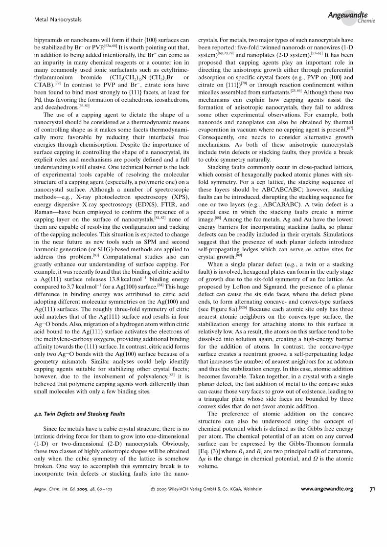
When a single planar defect (e.g., a twin or a stackingfault) is involved, hexagonal plates can form in the early stageof growth due to the six-fold symmetry of an fcc lattice. Asproposed by Lofton and Sigmund, the presence of a planardefect can cause the six side faces, where the defect planeends, to form alternating concave- and convex-type surfaces(see Figure 8a).[52b] Because each atomic site only has threenearest atomic neighbors on the convex-type surface, thestabilization energy for attaching atoms to this surface isrelatively low. As a result, the atoms on this surface tend to bedissolved into solution again, creating a high-energy barrierfor the addition of atoms. In contrast, the concave-typesurface creates a reentrant groove, a self-perpetuating ledgethat increases the number of nearest neighbors for an adatomand thus the stabilization energy. In this case, atomic additionbecomes favorable. Taken together, in a crystal with a singleplanar defect, the fast addition of metal to the concave sidescan cause those very faces to grow out of existence, leading toa triangular plate whose side faces are bounded by threeconvex sides that do not favor atomic addition.
The preference of atomic addition on the concavestructure can also be understood using the concept ofchemical potential which is defined as the Gibbs free energyper atom. The chemical potential of an atom on any curvedsurface can be expressed by the Gibbs-Thomson formula[Eq. (3)] where R1 and R2 are two principal radii of curvature,Dm is the change in chemical potential, and W is the atomicvolume.
Metal NanocrystalsAngewandte
Chemie
71Angew. Chem. Int. Ed. 2009, 48, 60 – 103 � 2009 Wiley-VCH Verlag GmbH & Co. KGaA, Weinheim www.angewandte.org

Dm ¼ gWð1=R1 þ 1=R2Þ ð3Þ
For a convex surface, the curvature is positive, thus thechemical potential of an atom on such a surface is higher thanthat on a flat surface. In contrast, the chemical potential isquite low on a concave surface. As atoms prefer the site withthe lowest chemical potential, atomic addition will only occuron concave-type sides.
For the growth of five-fold twinned nanorods, multipletwin defects are involved. It has been proposed that thenanorods grow from decahedral seeds along the axis parallelto the twin planes (Figure 8b).[52a] If a decahedron is viewed asan assembly of five tetrahedrons joined together by twinplanes, each vertex is equal to a point where a concave-typeface grows out, leaving five edges and two axial points asconvex-type faces. In this case, a decahedral seed should growinto a large decahedron instead of a five-fold twinnednanorod, but this case is not observed in a typical synthesis.Therefore, another factor must be responsible for theanisotropic growth. In principle, when atoms in a decahedronare located far from the central axis, the lattice strain willbecome extremely high. This strain energy will be greatlyincreased when a decahedral seed grows laterally. In contrast,elongation of the decahedron along the axis parallel to thetwin planes does not cause any increase in strain energy. As aresult, decahedral seeds preferentially grow along the axialdirection into five-fold twinned nanorods and then nanowires.As another requirement for this type of growth, there must bea capping agent in the solution that can stabilize the newlyformed {100} side faces through chemisorption.
4.3. Shape Evolution during Crystal Growth
Crystallographers call the characteristic shape of a crystal(or the relative area of its faces) its “habit”.[90] A primaryfactor determining the habit of a crystal is the relative rates atwhich different crystal planes grow. Consequently, duringcrystal growth, the habit of a crystal can change if there is amix of different facets on the surface. In fact, crystal growth isa very dynamic process! For example, consider an imaginary2-D octagonal crystal with alternating fast and slow growingedges. As Figure 9 illustrates, continued crystal growth will
result in an elongation of the slow growing edges at theexpense of the faster growing ones, producing a square,faceted with the slow growing edges. In 3-D, if the fastgrowing edges correspond to the corners of a truncated cube,the final crystal shape will then be a cube faceted by the slowgrowing planes. In contrast, if in 3-D the fast growing edgescorrespond to the faces of a truncated cube, the final crystalshape will be an octahedron faceted by those slow growingplanes. Such a dynamic evolution can occur to selectivelyenlarge one set of crystallographic facets at the expense ofothers on a nanocrystal, yielding new shapes. For example,Yang and co-workers have shown that an fcc single crystal canevolve from a cube to a cuboctahedron and then to anoctahedron, with an increasing ratio of {111} to {100} facetareas.[91] As Figure 10 shows, when metal atoms add to the{100} faces of a nanocube, they migrate to the edges of theface resulting in the elongation of the {111} facets. As thisprocess continues, the cubes will be transformed into cuboc-tahedrons and eventually octahedrons. This shape evolutionprocess has also been known as overgrowth. Interestingly, asdiscussed in Section 4.1, the introduction of a capping agent toa synthesis can alter the growth rates of the different facets,thus dramatically altering the final nanocrystal shape.
4.4. Seeded Growth: Epitaxial versus Non-Epitaxial
With regards to nanocrystal growth, pre-formed nano-crystals with well-defined facets can be added to a synthesis
Figure 8. a) Hexagonal plate with a single twin plane, which containsconcave-type (A) and convex-type (B) faces. The concave-type surfaceserves as the primary site for atomic addition, facilitating the trans-formation of hexagonal plates into triangular plates. b) Decahedronseed (left) and five-fold twinned rod (right). The five variants in thedecahedron are separated by {111}-type twin planes. In the five-foldtwinned rod, the side faces are {100} and the end faces are {111}faces. The green and orange colors represent the {100} and {111}facets, respectively. Twin planes are delineated with red lines (modifiedwith permission from ref. [52b], copyright 2005 Wiley-VCH).
Figure 9. Shape evolution during the successive stages of growth foran imaginary 2-D crystal. a) Rapid addition to the y-edges (relative tothe x-edges) results in the elongation of the x-edges and the eventualdisappearance of the y-edges, and b) vice versa. The length of anarrow is directly proportional to the growth rate. When the crystal isenclosed by a single set of planes, the shape will become stable overgrowth time unless the surface is modified again due to etching,Ostwald ripening, and/or capping.
Y. Xia et al.Reviews
72 www.angewandte.org � 2009 Wiley-VCH Verlag GmbH & Co. KGaA, Weinheim Angew. Chem. Int. Ed. 2009, 48, 60 – 103

and serve as primary sites for nucleation (in this case,heterogeneous) and crystal growth. If, during crystal growth,the added metal atoms continue with the same crystalstructure as the seed, then it is an epitaxial process. Thiscondition is achieved when the seeds have the same chemicalidentity as the growth atoms, and this approach has been usedmost commonly to grow Au nanorods from Au seeds (seeSection 5.3).[92] Amazingly, the twin structure of the seed istransferred to the entire nanocrystal via epitaxial growth,although the final nanocrystal shape may deviate from that ofthe initial seed due to the factors outlined in Sections 4.1 and4.3.
Epitaxial growth also can be achieved when the seeds andadded atoms are chemically different; however, in this case, itis more accurately referred to as heteroepitaxial growth.Heteroepitaxy has long been used in gas-phase deposition toprepare functional heterostructures or junctions but had notbeen explored in the solution phase until recently.[93] As aprerequisite for heteroepitaxial growth, there must be a closelattice match between the seed and the deposited atoms (e.g.,Pd and Pt have a lattice mismatch of only 0.77%). Asdiscussed in more detail in Sections 5.1 and 5.4, this approachcan be used to prepare bimetallic core–shell nanocrystals(Figures 11 and 12), in which the core consists of the initialseed used for heteroepitaxial deposition.[94] When there is alarge lattice mismatch between the seed and the depositedatoms (e.g., Au and Pt have a lattice mismatch of 4.08 %),heteroepitaxial growth is unfavorable due to high strainenergy. As a result, non-conformal growth ensues, giving riseto shapes not necessarily predicted from the structure of theseed (see Section 5.3). Very recently, Xie and co-workersconsidered this approach more fully and found that even withlarge lattice mismatches, conformal growth was possible, withAu/Pd core–shell cubes (lattice mismatch 4.71 %) beingproduced; they suggested that, in addition to minimal latticemismatch (< 5%), the metal bond energies of the twocomponents were important for conformal growth.[94b]
Figure 10. Overgrowth process of Ag nanocrystals, in which Ag atomsare continuously deposited onto the {100} facets of a Ag nanocube toeventually result in an octahedron enclosed by {111} facets (modifiedwith permission from ref. [67a], copyright 2006 Wiley-VCH).
Figure 11. Electron microscopy characterization of the binary Pt/Pdcore–shell nanocrystals obtained through the heteroepitaxial deposi-tion of Pd on cubic Pt seeds: a,b) cube; c, d) cuboctahedron; and e, f)octahedron (modified with permission from ref. [94a], copyright 2007Nature Publishing Group).
Figure 12. Electron microscopy characterization of the binary Pd/Ptcore–shell nanoplates obtained through the heteroepitaxial growth ofPt shells on Pd nanoplate seeds. a–d) STEM images and the corre-sponding cross-sectional compositional line profiles of Pd/Pt core–shell nanoplates for a,b) hexagonal and c, d) triangular plates.e, f) HRTEM images taken from the side faces of the Pd/Pt core–shellnanoplates, which show the continuous lattice fringes from the Pdcore (lattice spacing: 2.22 �) to the Pt shell (lattice spacing: 2.29 �)(modified with permission from ref. [94c], copyright 2008 AmericanChemical Society).
Metal NanocrystalsAngewandte
Chemie
73Angew. Chem. Int. Ed. 2009, 48, 60 – 103 � 2009 Wiley-VCH Verlag GmbH & Co. KGaA, Weinheim www.angewandte.org

5. Case Studies of Different Metals
The first example of the shape-controlled synthesis ofmetal nanocrystals was demonstrated by El-Sayed and co-workers with the preparation of Pt nanocubes and tetrahe-drons.[95] Shortly thereafter, Au nanorods,[96] FePt nano-cubes,[97] Ag nanoplates,[98] and Ag nanocubes[78a] weredemonstrated. Since these early examples, there have beenmany reports of other metals being prepared as shape-controlled nanocrystals and of other shapes. Here, we surveythis work so to highlight the principles outlined in Sections 1–4, beginning our discussion with Pd because the largestnumber of shapes has been generated for this noble metal. Aswe hope to convey, Pd is an ideal model system for under-standing the synthesis of metal nanocrystals with well-controlled shapes, and the principles that direct Pd nano-crystal growth can be easily extended to other fcc metals andalloys.
5.1. Pd
Palladium is most interesting for its extraordinary capa-bility to absorb H2. Incredibly, it can absorb up to 900 times itsown volume of H2 at room temperature and atmosphericpressure, making it an efficient and safe storage medium forH2. When it is finely divided, Pd also can serve as a goodcatalyst for hydrogenation and dehydrogenation reactions aswell as cracking. In organic chemistry, a large number ofcarbon–carbon bond forming reactions such as Heck orSuzuki coupling are facilitated by catalysts based on Pd0 or itscompounds.[99] The largest use of Pd today is probably incatalytic converters, which convert up to 90% of the harmfulgases (including hydrocarbons, CO and NO) from autoexhaust into less harmful substances such as CO2 and N2.All of these applications could be greatly enhanced with theuse of Pd nanocrystals enclosed by the same appropriatefacet.[100]
The predominant shape of Pd nanocrystals is the Wulffpolyhedron when the sample is prepared by relatively fastreduction or decomposition. Experimentally, Na2PdCl4 is themost commonly used precursor for the reduction routebecause of its stability in air and good solubility in a varietyof solvents. In this case, no additional Cl� is needed to initiateoxidative etching as this anion will be released from the saltprecursor during reduction. Pd(NO3)2 is also commerciallyavailable and could be used as a precursor to Pd; however, it ishygroscopic and tends to hydrolyze to Pd(OH)2.
[101] Ingeneral, alcohols, glycols, and hydrazine can all serve as thereductant source to ensure fast reduction of various Pdprecursors.[60,102] Among these options, ethylene glycol offersa unique example as it serves as both the solvent and primaryreductant at the temperatures commonly used for Pd nano-crystal synthesis. For a typical synthesis conducted in air at110 8C with Na2PdCl4 as a precursor, the product sampledafter 5 min contained 90% Wulff polyhedrons (ca. 8 nm insize) and 10% multiply twinned particles (MTPs, includingdecahedrons and icosahedrons).[60a] When the reaction wasprolonged to 3 h, all the MTPs were eliminated due to
oxidative etching, leaving behind only Wulff polyhedrons(Figure 13 a),[64a] and if allowed to continue beyond 3 h, eventhese single-crystal structures were subjected to oxidativeetching. As a result, it is difficult to grow Pd nanocrystalslarger than 10 nm using this method. Additionally, becausePVP is too big to have a significant capping effect on verysmall nanocrystals, these Pd nanocrystals < 10 nm in sizecannot evolve into perfect cubes, but rather maintain theirWulff polyhedral structure.
While the above work illustrates the power that oxidativeetching can have in controlling the population of twinnedstructures in solution, the preparation of single-crystal Pdnanocrystals encased with only one type of facet (e.g., cubesas compared to Wulff polyhedrons) is desirable, particularlyfor applications in catalysis. To achieve this goal, twoapproaches have been explored: 1) modulation of reduc-
Figure 13. Electron microscopy images of single-crystal Pd nanocrys-tals: a) Wulff polyhedrons prepared in ethylene glycol with PVP as acapping agent (modified with permission from ref. [64a], copyright2005 American Chemical Society); b) slightly truncated nanocubesprepared in ethylene glycol with PVP as a capping agent and FeIII
species as an etchant (modified with permission from ref. [78b],copyright 2005 American Chemical Society); c) nanocubes preparedwith PVP as a reductant in water and in the presence of KBr;d) nanobars prepared in a mixture of 90.9% water and 9.1% ethyleneglycol, in the presence of KBr; e) nanorods prepared in a mixture of72.7% ethylene glycol and 27.3% water, in the presence of KBr(modified with permission from ref. [64d], copyright 2007 AmericanChemical Society); f) octahedrons prepared with citric acid as areducing agent and capping agent at a high concentration of Pdprecursor (modified with permission from ref. [80], copyright 2007Wiley-VCH).
Y. Xia et al.Reviews
74 www.angewandte.org � 2009 Wiley-VCH Verlag GmbH & Co. KGaA, Weinheim Angew. Chem. Int. Ed. 2009, 48, 60 – 103

tion/oxidation conditions during the polyol synthesis and2) use of a capping agent much smaller than PVP. In the firstapproach, Pd nanocubes with edge lengths up to 50 nm wereprepared by adding FeIII species to a polyol synthesis at 90 8C.In this case, the addition of such species was found to enhancethe oxidation of Pd0, thus effectively reducing the number ofseeds formed during the nucleation stage.[78b] At the sameconcentration of precursor, the presence of fewer seedsmeans a larger size for the final product. Using this approach,the final size of the Pd nanocrystals could be controllablyincreased simply by increasing the concentration of the FeIII
species. Due to the capping effect of PVP, these larger single-crystalline nanocrystals adopted a cubic shape, with someslight corner truncation (Figure 13 b).
Considering the second approach, Br� was added as asmaller capping agent and found to promote the developmentof {100} facets, allowing for the generation of Pd nanocubes8 nm in edge length (Figure 13c).[64d] This synthesis wascarried out in water with PVP as a reductant, and both XPSand EDX analyses suggest that Br� is capable of chemisorb-ing onto the {100} facets of very tiny Pd nanocrystals. In thisway, the selective chemisorption of Br� alters the order ofsurface energies for different facets, allowing for nanocubes,not Wulff polyhedrons, to be produced at small sizes.
During the course of this work, it was also found that Br�
could initiate anisotropic growth for cubic nanocrystals if thereduction rate was enhanced by introducing ethylene glycol asa reductant.[64d] In one example, Pd nanobars enclosed by{100} facets and with a square cross-section were synthesizedfrom a reaction containing ethylene glycol, water, PVP, andKBr (see Figures 13d and e). The aspect ratio of the nanobarswas observed to increase with an increase in the concentrationof ethylene glycol. In a second example, Pd nanoneedles witha rectangular cross-section of decreasing area were preparedin water with ascorbic acid and sodium citrate as co-reductants and CTAB as a capping agent.[103] How and whysuch anisotropic growth occurs are yet to be fully understood;however, localized oxidative etching in the presence of Br�
appears to be involved. As the chemisorbed Br� layerprevents the further addition of Pd atoms to the Pd nano-crystal, the surface has to be activated in some way tocontinue the growth process. For a cubic nanocrystal,localized oxidative etching could selectively activate onlyone of its six faces for atomic addition. Then, if enough Pdatoms can be supplied to the etched site by acceleratedreduction, atomic addition will surpass the removal of atomscaused by etching at that face, breaking cubic symmetry andeventually leading to the formation of a nanobar. In this case,a relatively high reduction rate, achieved by having a highconcentration of ethylene glycol in water, is needed toprovide sufficient Pd atoms for continuous growth. For aWulff polyhedral nanocrystal, selective activation of anoctagonal face by localized oxidative etching leads to ananorod whose side surfaces are a mix of both {100} and {110}facets. As for the formation of Pd nanoneedles, the exactmechanism still needs to be resolved. We believe that the Br�
from CTAB may play a critical role, in addition to the cappingeffect of the surfactant.
In addition to single-crystal seeds, the Pd system is rich intwinned structures.[104] As discussed in the beginning of thissection, the retention of twinned seeds produced duringpolyol reduction is difficult to achieve due to the intrinsicallycorrosive environment. Yet, in a recent study, we found thatcitric acid or citrate ions could protect such seeds fromoxidative etching.[66,80] There are two possible mechanisms forexplaining this observation: 1) they can compete with oxygenadsorption and thus reduce the amount of oxygen immobi-lized on the Pd surfaces or 2) they can react with and exhaustthe adsorbed oxygen. Regardless of the mechanism, itbecomes possible to stabilize twinned Pd nanocrystalsenclosed by {111} facets—decahedrons and icosahedrons—and even single-crystal octahedrons, presumably due to thestrong binding of citrate to the {111} facets.
The key to producing one of these nanocrystal shapes tothe exclusion of the others is to control the population of thevarious seed types in a synthesis. Amazingly, using a simplewater-based system in which only Na2PdCl4, PVP, and citricacid were added, we were able to achieve these various seedsand tune their yields simply by controlling the concentrationand reduction rate of the precursor.[66, 80] It has been shown bysimulation that icosahedral, decahedral, and Wulff polyhedralclusters are favored for Pd at small (N< 100), medium (100<N< 6500), and large sizes (N> 6500), respectively.[54] Thus, togenerate Wulff polyhedral seeds, and eventually octahedrons,a high atomic concentration is required because the numberof Pd atoms in a seed is highly dependent on the atomicconcentration in the solution. Two factors affect the atomicconcentration: 1) the reduction rate and 2) the concentrationof precursor. As citric acid is a mild reducing agent, the Pdprecursor concentration has to be kept relatively high in thissynthesis. When this condition is met, Pd octahedrons areproduced in over 90% yields (Figure 13 f). The same protocolcan be used to generate Pd decahedrons in high yields. In thiscase, the concentration of citric acid or citrate ions has to beincreased to ensure sufficient capping of the {111} facets, thusreducing the surface energy of the {111} facets and compen-sating for the extra strain energy caused by twinning. Forthese reasons, decahedral seeds can be stabilized effectivelyand grow into large decahedrons (Figure 14a) even thoughthe number of atoms might be above the favorable mediumrange for decahedral seed generation. Finally, when theatomic concentration is significantly lowered by reducing thePd precursor concentration, icosahedral seeds become favor-able due to the slow addition of Pd atoms. As a result, Pdicosahedrons become the major product (Figure 14b).[66, 80]
Besides citric acid, ascorbic acid may be used as a reducingagent. When it was used at 80 8C in the presence of Br� ,anisotropic growth of decahedral seeds was induced, resultingin pentagonal nanorods with their side {100} faces presumablystabilized by Br� .[68] Although there is modest oxidativeetching in this system, these five-fold twinned nanorods canbe stable for a long period of time. In the same synthesis, rightbipyramids were also formed from singly twinned seeds, withtheir {100} facets being stabilized with Br� . In general, theproduct typically consisted of 30% five-fold twinned nano-rods with length up to 150 nm, 17% MTPs, 18 % singlytwinned right bipyramids, and 35% nanocubes (Figure 14c).
Metal NanocrystalsAngewandte
Chemie
75Angew. Chem. Int. Ed. 2009, 48, 60 – 103 � 2009 Wiley-VCH Verlag GmbH & Co. KGaA, Weinheim www.angewandte.org

When the reaction temperature was increased to 100 8C,oxidative etching was greatly enhanced in this system. Thus,multiply twinned structures were rarely found in the finalproduct, although right bipyramids were still present up to30% in the final product distribution (Figure 14d).
When the reduction of the Pd precursor is greatly sloweddown, Pd nanoplates will be produced in high yields,indicating a kinetically controlled reaction. Such nanoplatescan have a triangular or hexagonal cross-section, and as wasobserved in some of these syntheses, hexagonal plates canevolve into triangular plates as their sizes are increased. Sucha transformation likely occurs by the mechanism proposed byLofton and Sigmund (see Section 4.2).[52b] Many differentapproaches have been developed to slow down the generationof Pd atoms.[58–60, 105] In polyol syntheses, the net reduction canbe slowed through the introduction of FeIII species and the O2/
Cl� pair, both oxidative etchants for Pd0.[60] For the O2/Cl�
pair, etching can be enhanced by adding an acid. For FeIII
species, adjusting their concentration allowed the reductionrate to be precisely controlled so to generate triangular orhexagonal Pd nanoplates (see Figure 14 e for triangularnanoplates). As a second approach, the reduction rate canbe kept low by using a mild reducing agent (e.g., PVP,formate, methanol, or glycolate) at low temperatures. Forexample, the chain ends of commercially available PVP havebeen found to be terminated with a hydroxy group using13C NMR spectroscopy.[59a] Such a polymer, just as with long-chain alcohols, can serve as a mild reducing agent forkinetically controlled syntheses including those of Pd nano-plates (Figure 14 f).[59b] In practice, controlling the ratio ofPVP to precursor as well as the molecular weight of PVP canprovide further control of the reduction rate. As a thirdapproach, Pd atoms can be slowly generated through decom-position of a Pd–octanedionate complex in the presence ofvarious tetraalkylammonium salts to form hexagonal Pdnanoplates in high yields.[58a] Finally, a RNA-mediated syn-thesis of Pd nanoplates has been reported.[105] In this case, theRNA sequence was found to be critical to the formation ofplate-like morphology, and it was suggested that the RNAprovided a critical folding motif for interaction with theprecursor complex that directed the formation of nanoplates.Interestingly, by changing the RNA sequence, Pd nanocubescould be obtained through a similar reaction. It is worthpointing out that the sugar unit in RNA contains hydroxygroups, which might also be involved in reducing the Pdprecursor.
Recently, it has been shown that polyhedral Pd nano-crystals with edge lengths > 30 nm could be obtained byheteroepitaxial seeded growth, in which preformed Pt nano-cubes (such as those discussed later in Section 5.4) wereadded to a synthesis and served as sites for nucleation and thecontrolled overgrowth of Pd nanocrystals.[94a] The finalproducts exhibited a well-defined core–shell Pt/Pd structuremade possible by the minimal lattice mismatch between Ptand Pd. By controlling the concentration of NO2 presentduring the synthesis, the growth rates along the h100i andh111i directions could be varied to produce octahedrons,cuboctahedrons, and cubes (Figure 11). In these cases, theNO2 was generated in situ from the decomposition of HNO3
in the presence of HCl. The generated NO2 can thendissociate on the Pd surface, giving NO and atomic oxygen;the NO will desorb while the atomic oxygen should remain onthe surface and modulate the growth rates of different facets.
5.2. Ag
Historically, silver has most widely been used in jewelry/metal-craft and photography (where photosensitive Aghalides are reduced).[9] More recently, Ag, particularly innanoparticle form, has been finding use as a catalyst invarious oxidation and oxidative coupling reactions (e.g.,formaldehyde production from methanol and air).[106] In fact,Ag nanoparticles are the only practical catalyst availabletoday for converting ethylene to ethylene oxide, an important
Figure 14. Electron microscopy images of Pd nanocrystals with twindefects: a) decahedrons prepared with citric acid as a reducing agentand capping agent at high concentrations for both Pd precursor andcitric acid (modified with permission from ref. [80], copyright 2007Wiley-VCH); b) icosahedrons prepared with citric acid as a reducingagent and capping agent at a low concentration of Pd precursor(modified with permission from ref. [80], copyright 2007 Wiley-VCH);c) five-fold twinned nanorods (as a mixture with cubes) prepared withascorbic acid as a reductant in water and in the presence of bromide;d) single-twinned right bipyramids (as a mixture with cubes) preparedwith ascorbic acid as a reductant in water and in the presence ofbromide (modified with permission from ref. [68], copyright 2007Elsevier); e) triangular nanoplates prepared in ethylene glycol and inthe presence of FeCl3 and HCl (modified with permission fromref. [60], copyright 2005 American Chemical Society); f) hexagonalnanoplates prepared with PVP as a reductant in water (modified withpermission from ref. [59b], copyright 2006 American Chemical Soci-ety).
Y. Xia et al.Reviews
76 www.angewandte.org � 2009 Wiley-VCH Verlag GmbH & Co. KGaA, Weinheim Angew. Chem. Int. Ed. 2009, 48, 60 – 103

industrial precursor. Silver nanostructures also have been thesource of extensive research for their widespread use assubstrates for SERS, optical labeling, and near-field opticalprobing.[15] Experimentally, AgNO3 is the most commonlyused precursor when preparing Ag nanocrystals via thereduction route because of its good solubility in polarsolvents. This compound, however, is highly sensitive tolight, and as discussed in Section 2.2, this sensitivity can have asignificant effect on the nature of Ag species in solution. As aresult, cautions must be taken in the storing and handling ofthis precursor.
Like other fcc metals, icosahedral, decahedral, and Wulffpolyhedral seeds and their corresponding nanocrystals are thethermodynamically favored products. Yet, according tosimulations, the size window that favors both Ag icosahedronsand decahedrons is much broader than with other metals(Table 2).[54] As a result, multiply twinned seeds typicallypredominate under most reaction conditions. Of course, themultiply twinned seeds can be selectively removed byoxidative etching just as in the Pd system (see Figure 7).[62]
In practice, however, oxidative etching with the Cl�/O2 pair isa slow process for the Ag system, with single-crystal productsonly being produced after a couple days of reaction. Thisoxidative etching process can be enhanced by the introduc-tion of a protonic acid (either by directly adding HCl orthrough the transformation from H2).[107] In these cases,single-crystal Ag nanocubes could be produced in less thanhalf day. It should be pointed out that Ag cuboctahedrons(Figure 15 a) and perfect nanocubes (Figure 15b) are onlyobserved once the Ag nanocrystals have grown past 20 nm, atwhich point PVP as a capping polymer can promote theformation of {100} facets. At smaller sizes, the single crystalsadopt a Wulff polyhedral (or spherical) profile so to minimizetheir overall surface area. While oxidative etching has provento be an extremely powerful tool for controlling the pop-ulation of twinned seeds in solution, the slowness of thisprocess in the Ag system hinders large-scale synthesis.
Recently, we reported a very rapid route to Ag nanocubesin which oxidative etching was not necessarily involved.[108] Inthis case, sulfide or hydrosulfide is added to ethylene glycol ata ppm level prior to the introduction of PVP and AgNO3.Upon AgNO3 addition, Ag2S clusters or nanocrystallites areformed, which can serve as primary sites for nucleation bycatalyzing the reduction of Ag+.[109] In a related study, Yangand co-workers also produced single-crystal Ag nanocubes ina matter of minutes, in this case by adding trace CuCl2 to a 1,5-pentanediol-based polyol synthesis.[67a] While the role of theCu salt was not discussed in their publication, it presumablyfacilitates single-crystal seed formation through a similarmechanism. Interestingly, they also showed that their Agnanocubes could grow in size to become truncated octahe-drons (Figure 15c) and then octahedrons (Figure 15 d).Although PVP was used in this synthesis, it seems unable toreduce the surface energy of {100} facets below that of the{111} facets and could be due to not enough PVP beingpresent during synthesis.
Besides PVP, the addition of Br� to a polyol synthesis canalso promote the formation of {100} facets and thus Agnanocubes (Figure 15 e).[110] Under the right conditions, Br�
can even induce anisotropic growth to transform Ag nano-cubes into nanobars with rectangular cross-sections (Figur-e 15 f).[63b] While the mechanism for such growth is not fullyunderstood, it is believed to be analogous to the case of Pdnanobars in which Br� chemisorption and localized oxidativeetching are involved. The function of Br� in the synthesis ofAg nanocrystals, however, is much more complicated thanthat of Pd because Ag is much more chemically active. Forexample, it has been observed that the addition of Br� to apolyol synthesis of Ag can induce oxidative etching eventhough Br� is less corrosive than Cl� . At high Br� concen-trations (60 mm, Ag:Br 1700:1), all twinned seeds areremoved; however, decreasing the concentration of Br� by50% removes only the most reactive multiply twinned seedsfrom the solution. As a result, a mixture of single-crystal andsingly twinned seeds remain, which can grow into Agnanocubes and right bipyramids, respectively (Figure 16 a).[63a]
Figure 15. Electron microscopy images of single-crystal Ag nanocrys-tals: a) cuboctahedrons prepared in ethylene glycol with PVP as acapping agent (modified with permission from ref. [62], copyright 2004American Chemical Society); b) nanocubes prepared in ethylene glycolwith PVP as a capping agent (modified with permission fromref. [78a], copyright 2002 American Association for the Advancementof Science); c) truncated octahedrons prepared in 1,5-pentanediol inthe presence of PVP and Cu2+ ions; d) octahedrons prepared in 1,5-pentanediol in the presence of PVP and Cu2+ ions (modified withpermission from ref. [67a], copyright 2006 Wiley-VCH); e) nanocubesprepared by a modified silver mirror reaction in the presence of Br�
with glucose as a reducing agent (modified with permission fromref. [110b], copyright 2005 American Chemical Society); f) nanobarsprepared in ethylene glycol in the presence of PVP and Br� (modifiedwith permission from ref. [63b], copyright 2007 American ChemicalSociety).
Metal NanocrystalsAngewandte
Chemie
77Angew. Chem. Int. Ed. 2009, 48, 60 – 103 � 2009 Wiley-VCH Verlag GmbH & Co. KGaA, Weinheim www.angewandte.org

Interestingly, the singly twinned seeds can also be inducedinto anisotropic growth by doubling the AgNO3 concentra-tion and reducing the reaction temperature, producing 1-DAg nanocrystals with a single twin plane running down theirlong axes. These unique Ag nanocrystals have been referredto as nanobeams (Figure 16 b).[69]
As with the singly twinned seeds, anisotropic growth ofdecahedral Ag seeds can be induced to facilitate theformation of 1-D nanocrystals such as nanorods and nano-wires. In these cases, however, the resulting crystal will have apentagonal cross-section (Figure 16c).[111–113] Although earlywork indicated that small nanoparticles of Pt or Ag wereneeded to promote anisotropic growth,[111] recent studies haveshown that such seeds are not necessary at all. Only AgNO3,ethylene glycol, and PVP are needed![70] PVP stabilizes the{100} side faces of nanowires, and the internal twin defects ofthe initial seeds induce the 1-D growth. In order to obtain
multiply twinned seeds (and thus nanowires) in high yields,oxidative etching has to be blocked during the synthesis. Thisrequirement has been achieved in the Ag system by simplybubbling an inert gas through the reaction solution[62] orthrough the addition of redox active metal salts, for example,FeII/FeIII or CuI/CuII, which increases the rate of Ag deposi-tion relative to oxidation.[65,114]
Besides those structures built upon thermodynamicallyfavored Wulff polyhedrons, it is possible to switch to kineti-cally favored structures. This condition can be met by slowingdown the generation of Ag atoms, just as in the Pdsystem.[115–117] The resulting Ag crystals are plate-like, similarto those prepared by Mirkin and co-workers in 2001 in whichAg nanoparticles were photo- or thermally transformed intonanoplates (Figure 16d) over a long period of time through anOstwald ripening mechanism.[98] To prepare Ag nanoplates byslowing down reduction, a mild reducing agent such as HO-terminated PVP, ascorbic acid, or glycylglycine is often used(Figure 16 e).[59] Alternatively, the precursor reduction can beslowed down by complexing the Ag+ ions with a stronglycoordinating polymer such as polyacrylamide (PAM) whoseamino groups can form complexes with Ag+ ions.[58b] Accord-ing to the Nernst equation, the redox potential of the Ag+/Agpair should be greatly reduced due to formation of such acomplex, which can in turn greatly reduce the reduction rateand favor the formation of nanoplates through kineticallycontrolled growth.
Finally, Ag nanobelts (Figure 16 f) have been observed,being prepared through a thermal transformation in a mannersimilar to the early nanoplate work.[61b] The growth mecha-nism responsible for this class of nanostructures remainsunresolved; however, the total free energy of a nanobeltshould be as high as that of a nanoplate due to the internalstrain caused by twinning and their generally large surfaceareas. These properties imply that the nanobelts are kineti-cally controlled products. It would be interesting to develop akinetically-controlled reduction route to such structures inhigh yields.
5.3. Au
The synthesis of Au nanocrystals with well-defined shapesappears to be one of the most popular subjects of researchover the past decade, as judged from the total number ofpublications per year on this subject. This trend, in large part,is due to the unique and often tunable properties of Aunanocrystals that include LSPR, biocompatibility, and easysurface modification. When combined together, Au nano-crystals represent an ideal platform for chemical and biolog-ical sensing as well as applications in nanomedicine. Forexample, Au nanoparticles can readily adsorb protein mole-cules onto their surfaces, causing a shift in the LSPR of thenanoparticles.[13] When coated with specific antibodies, theseimmuno-Au nanocrystals can be used to probe the presenceand position of antigens on cell surfaces as well as topotentially deliver therapeutic agents selectively.[14] Mostrecently, Au nanoparticles were discovered to displayunique catalytic properties for a variety of oxidation reac-
Figure 16. Electron microscopy images of Ag nanocrystals with twindefects: a) singly twinned right bipyramids prepared in ethylene glycolin the presence of PVP and Br� (modified with permission fromref. [63a], copyright 2006 American Chemical Society); b) singly twin-ned nanobeams prepared in ethylene glycol in the presence of PVPand Br� (modified with permission from ref. [69], copyright 2006American Chemical Society); c) five-fold twinned nanorods prepared inethylene glycol with PVP as a capping agent (modified with permissionfrom ref. [65], copyright 2005 American Chemical Society); d) nano-plates prepared by light-induced conversion of Ag nanospheres (modi-fied with permission from ref. [115a], copyright 2003 Nature PublishingGroup); e) nanoplates prepared in water with PVP as a reductant(modified with permission from ref. [59a], copyright 2006 Wiley-VCH);f) nanobelts formed by refluxing an aqueous dispersion of Ag colloids(modified with permission from ref. [61b], copyright 2003 AmericanChemical Society).
Y. Xia et al.Reviews
78 www.angewandte.org � 2009 Wiley-VCH Verlag GmbH & Co. KGaA, Weinheim Angew. Chem. Int. Ed. 2009, 48, 60 – 103

tions; however, the performance of these Au catalysts ishighly dependent on the size of the nanocrystal.[118]
There have been many demonstrated methods for con-trolling the shape of Au nanocrystals, and as with the Pd andAg systems, the selection of reductant, reaction conditions,and stabilizer are all critical to forming a particular shape. Asexpected, strong reducing agents, as typified by polyolreduction, facilitate the synthesis of thermodynamicallyfavored polyhedral Au nanocrystals.[119] There are, however,notable differences. For example, in contrast to the Ag and Pdsystems, the binding of PVP to Au does not appear sufficientlystrong to promote the formation of {100} facets and isprobably due to differences in surface reactivity. As a result,single-crystal and multiply twinned Au nanocrystals enclosedby {111} facets—octahedrons (Figure 17a), truncated tetra-hedrons (Figure 17 b), icosahedrons (Figure 17c), and deca-hedrons (Figure 17d)—predominate as compared to {100}
encased crystals that typify the Pd and Ag systems.[91, 120]
Interestingly, when Ag+ or Br� ions are present duringreaction, truncated (Figure 17e) or perfect Au nanocubes(Figure 17 f) result.[91, 121]
As observed in the Pd and Ag systems, when the reductionrate is substantially lowered, Au nanoplates will be produced,and this kinetic control can be achieved by using a mildreductant such as phenylenediamine, an extract from theplant lemongrass (Cymbopogon flexuosus), PVP, or glucose.Such kinetic control can also be achieved by performing thesynthesis at room temperature. The nanoplates usually havehexagonal or triangular profiles (Figures 18 a and b).[59b, 122] Aunanoplates may also be prepared by reducing the concen-tration of Au precursor in a synthesis. In this case, theconcentration of the generated metal atoms is never highenough to facilitate seeds favored by thermodynamics.Instead, the Au atoms appear to aggregate into small clusters,which then can agglomerate into larger nanocrystals.[123] As aresult of this aggregate assembly, twin defects or stackingfaults are introduced, which favor Au nanoplate formation.Finally, as in the Ag case, photo-induced Ostwald ripening ofAu nanoparticles results in Au nanoplates.[124] Yet, no matterwhich method is used, the resulting Au nanoplates have ahexagonal or triangular cross-section depending on thereaction rate and/or time.[125] As a special case of plate-likemorphology, Au nanobelts have also been prepared. In oneexample, HAuCl4 was reduced with ascorbic acid in a mixedsurfactant system containing sodium dodecylsulfonate(SDSn) and CTAB.[126] The reaction was performed belowroom temperature to ensure sufficiently slow reduction, while
Figure 17. Electron microscopy images of Au nanocrystals: a) octahe-drons prepared with PVP as a capping agent in polyethylene glycol 600(PEG 600) (modified with permission from ref. [120b], copyright 2007Wiley-VCH); b) truncated tetrahedrons prepared with PVP as a cappingagent in tetraethylene glycol (modified with permission fromref. [120e], copyright 2008 American Chemical Society); c) icosahe-drons prepared in ethylene glycol with a low concentration of Auprecursor (modified with permission from ref. [91], copyright 2004Wiley-VCH); d) decahedrons prepared in diethylene glycol with a highconcentration of PVP (modified with permission from ref. [120e],copyright 2008 American Chemical Society); e) truncated nanocubesprepared in 1,5-pentanediol in the presence of Ag+ ions with PVP as acapping agent; f) nanocubes prepared in 1,5-pentanediol in thepresence of Ag+ ions with PVP as a capping agent (modified withpermission from ref. [121b], copyright 2006 American Chemical Soci-ety).
Figure 18. Electron microscopy images of anisotropic Au nanocrystals:a) hexagonal nanoplates prepared with ortho-phenylenediamine as areductant (modified with permission from ref. [122b], copyright 2004Wiley-VCH); b) triangular nanoplates prepared with Sargassum sp. as areductant (modified with permission from ref. [122i], copyright 2005American Chemical Society); c) nanobelts prepared with ascorbic acidas a reducing agent and SDSn and CTAB as surfactants (modified withpermission from ref. [126], copyright 2008 American Chemical Soci-ety); d) five-fold twinned nanorods prepared by a seeding process withCTAB as a capping agent (modified with permission from ref. [79a],copyright 2001 American Chemical Society).
Metal NanocrystalsAngewandte
Chemie
79Angew. Chem. Int. Ed. 2009, 48, 60 – 103 � 2009 Wiley-VCH Verlag GmbH & Co. KGaA, Weinheim www.angewandte.org

the belt-like morphology was attributed to a cooperativeeffect between the mixed surfactants (Figure 18c). Withglucose as a reductant, Au nanobelts have also been preparedunder sonication.[127]
While the preceding paragraphs reiterate the importanceof reduction kinetics for shape control, seeded growth, aspioneered by the Murphy group, has proven to be extremelypowerful in the Au system.[79, 128] In this method, small Aunanoparticles are first prepared by fast reduction with astrong reducing agent. These seeds are then used to initiatefurther nanocrystal growth when additional precursor isadded and then slowly reduced in the presence of a surfactantor polymeric stabilizer. Most commonly, HAuCl4 is reducedwith ascorbic acid in the presence of citrate-capped twinnedAu seeds and CTAB to produce anisotropic Au nanorods andnanowires. These 1-D nanostructures have a pentagonalcross-section with end surfaces being terminated by {111}facets; the side surfaces are poorly defined but are enclosedby either {100} or {110} facets, or both (Figure 18d).[129]
Interestingly, when CTAB-capped single-crystal seeds areused and Ag+ ions are added to the synthesis, 1-D single-crystal nanorods enclosed by {110} side facets and {100} endfacets were observed (Figure 19 a).[128,130] In this case, the Ag+
is thought to be reduced preferentially on the {110} facets dueto an underpotential deposition process. Strong CTAB bind-ing to the deposited Ag via Br� can then prevent Audeposition to the {110} faces, resulting in anisotropic growth.Besides Br� and Ag+ ions, the concentrations of Au seeds andAu precursor can be manipulated to tune the nanocrystalshape. For example, when the concentration of seeds relative
to Au atoms is low, overgrowth of Au nanocrystals ispossible.[121, 131] For Au nanocrystals with truncated cubic oroctahedral shape, such overgrowth can lead to the formationof branched structures, including monopods, multipods (Fig-ure 19b), and flower-like structures.[131a,b,f] For Au nanorods,such overgrowth leads to dog bone (Figure 19c), dumbbell(Figure 19 d), and bipyramid nanostructures.[131c–e]
As a variant of these seeded growth methods, Yang andco-workers extended their heteroepitaxial method to prepareAu nanorods.[94a] In this example, single-crystal Pt nanocubeswere used to seed Au nanocrystal growth. In contrast to theirPt/Pd work discussed in Section 5.1, the lattice mismatchbetween Pt and Au is much greater (4.08 % mismatch versus0.77% for Pt/Pd), giving rise to non-conformal growth. As aresult, Au nanorods with incorporated Pt nanocubes areproduced in high yield.[94a]
Besides these seeding methods, single-crystal Au nano-rods and nanowires can be synthesized by electrochemical[96]
and photochemical methods.[132] Interestingly, in both cases,Br� is necessary. In the seeded growth of Au nanorods, Br� isalso present, originating from the CTAB. It has beenspeculated that CTAB might form micelles to induce anddirect 1-D growth; however, a recent study revealed that theorganic tail of CTAB was not necessary for Au nanorodformation.[64d] These observations, in combination with theexamples of 1-D growth in the Pd and Ag systems, suggestthat Br� might be more critical to 1-D growth than the alkylchain of CTAB. Besides Au rods and wires, polyhedral Aunanocrystals including decahedrons, cubes, and octahedronshave been prepared using seeded growth processes.[133]
As an interesting example of 1-D Au nanocrystal growth,very recently, we and others reported the synthesis ofultrathin Au nanowires with diameters < 2 nm.[134] Thesestructures formed through a unique growth process in which apolymeric strand of oleylamine–AuCl complex is first formedthrough aurophilic interaction when mixing AuCl and olyel-amine in hexane.[134a] The resulting complex can best bedescribed as a linear chain composed of a AuI···AuI backbonethat is surrounded by oleylamines (Figure 20a). By slowlyreducing the strands, with the aid of Ag nanoparticles,ultrathin Au nanowires are produced (Figure 20 b). Interest-ingly, a HRTEM study reveals that these wires grow along the< 111> direction, which is likely due to their unique growthmechanism (Figure 20c).
5.4. Pt
Platinum is an extremely valuable metal due to itsexceptional and unique properties as a catalyst for COoxidation in catalytic converters, the H2/O2 reaction in fuelcells, nitric acid production, and petroleum cracking, amongothers.[7c] It can also be used as a stable electrode material. AsPt is particularly expensive, there is a real incentive to reducethe amount of Pt required in processes where it is essential. Tothis goal, much research has been devoted to size reduction ofPt catalysts so to maximize the surface area. Researchers alsohave emphasized the improved selectivity of Pt nanocatalyststo which the exposure of crystal facets more intrinsically
Figure 19. Electron microscopy images of various Au nanocrystalsprepared by a seeding process: a) nanorods prepared in the presenceof Au seeds and Ag+ ions and with CTAB as a capping agent (modifiedwith permission from ref. [128d], copyright 2005 American ChemicalSociety); b) multipods formed through an overgrowth mechanism(modified with permission from ref. [131a], copyright 2004 AmericanChemical Society); c) dog bone-shaped nanocrystals formed throughan overgrowth mechanism (modified with permission from ref. [128d],copyright 2005 American Chemical Society); d) dumbbell-shaped nano-crystals formed through an overgrowth mechanism (modified withpermission from ref. [131c], copyright 2005 Wiley-VCH).
Y. Xia et al.Reviews
80 www.angewandte.org � 2009 Wiley-VCH Verlag GmbH & Co. KGaA, Weinheim Angew. Chem. Int. Ed. 2009, 48, 60 – 103

active for a particular process would be beneficial. In theseways, the shape-controlled synthesis of Pt nanocataysts wouldbe very beneficial.
In contrast to the Pd, Ag, and Au cases, twinned structuresof Pt rarely form.[135] This probably arises from the highinternal strain energy associated with Pt twinned crystals.[136]
Since the first publication of Pt cubes, tetrahedrons, andtruncated octahedrons by the El-Sayed group in 1996, mucheffort has been devoted to the synthesis that involves thereduction of K2PtCl4 by H2 in the presence of sodiumpolyacrylate as a capping agent.[95,137] It was observed thatthe Pt tetrahedrons produced initially evolved into truncatedoctahedrons and eventually cubes through the deposition ofPt atoms on the exposed {111} facets.[58b] This selective atomicaddition to {111} facets seems to be related to the differentcapping abilities at various facets.[58b] The concentration of thecapping agent has also been shown to influence this evolutionin shape.[95] In related work, Pt nanocubes (Figure 21a) andcuboctahedrons (Figure 21 b) were prepared by reducingK2PtCl4 with H2 generated in situ from NaBH4 decomposi-tion. In these studies, tetradecyltrimethylammonium bromide(TTAB) was used as a surfactant. Interestingly, switching to amilder reducing agent, ascorbic acid, led to the formation ofPt nanodendrites (Figure 21c).
More recently, the polyol reduction method was used tosynthesize Pt nanocrystals in the presence of PVP and Ag+ asan ionic mediator.[138] In these studies, it was found that, just asin the seeded growth of Au nanorods, the addition of Ag+ can
affect the final nanocrystal shape. Again, Ag+ enhancescrystal growth along the h100i axis, but in this case facilitatingthe formation of Pt octahedrons. Like the case of Au,overgrowth on truncated octahedrons of Pt can lead to theformation of branched structures. This phenomenon has onlybeen observed at a low concentration of seeds and highconcentration of Pt atoms. To meet these criteria, twostrategies have been employed. In the first system, oxidativeetching by FeIII species was coupled to a polyol reductionprocess to keep the initial concentration of Pt seeds extremelylow.[135b] Then, by continuously bubbling N2 through thereaction, oxidative etching was blocked so that a highconcentration of Pt atoms could be generated and persist.In this way, Pt cuboctahedral seeds could grow into tetrapodsthrough the overgrowth on their {111} corners (Figure 21 d).The second system relied on reduction with H2, and a highconcentration of Pt precursor was used to ensure the
Figure 20. a) Formation of a polymeric strand of oleylamine–AuClcomplex; b) TEM image of ultrathin Au nanowires with an averagediameter of 1.8 nm obtained by reducing the oleylamine–AuCl complexwith 10 nm Ag nanoparticles in hexane; c) HRTEM image showingh111i growth direction for most of the nanowires (modified withpermission from ref. [134a], copyright 2008 American Chemical Soci-ety).
Figure 21. Electron microscopy images of Pt nanocrystals with differentshapes: a) nanocubes prepared in the presence of TTAB with a highconcentration of NaBH4; b) cuboctahedrons prepared in the presenceof TTAB with a low concentration of NaBH4 (modified with permissionfrom ref. [144a], copyright 2007 American Chemical Society); c) nano-dendrites prepared with ascorbic acid as a reducing agent (modifiedwith permission from ref. [143b], copyright 2004 American ChemicalSociety); d) tetrapods prepared by a polyol process using FeIII speciesto reduce the number of seeds at the nucleation stage (modified withpermission from ref. [135b], copyright 2005 Wiley-VCH); e) nanowiresprepared by a polyol process using FeIII species to slow down thereduction (modified with permission from ref. [135a], copyright 2004American Chemical Society); f) nanowire network prepared in a two-phase water–chloroform system in the presence of CTAB with NaBH4
as a reducing agent (modified with permission from ref. [144b],copyright 2007 American Chemical Society).
Metal NanocrystalsAngewandte
Chemie
81Angew. Chem. Int. Ed. 2009, 48, 60 – 103 � 2009 Wiley-VCH Verlag GmbH & Co. KGaA, Weinheim www.angewandte.org

necessary overgrowth.[139] Since these initial reports, a numberof related methods have been used to synthesize branched Ptnanostructures, including the very recent demonstration byEl-Sayed and co-workers who used tetrahedral Pt seeds togrow single-crystal star-like Pt nanostructures with up tothirty arms.[140]
Single-crystal Pt nanowires can be obtained under thesame conditions as in the aforementioned polyol synthesis forPt tetrapods; however, the reaction must be conducted in air,not N2 (Figure 21e).[135a] In this case, precursor reduction iskept slow for the entire reaction. An HRTEM study of thesePt nanowires revealed that they grow along the h111i axis, justlike the ultrathin Au nanowires formed by reduction ofoleylamine–AuCl complexes. The mechanism for Pt nanowiregrowth along the h111i axis remains mysterious, althoughautocatalytic nucleation might be involved.[35] Mainly, withsuch slow reduction, the concentration of Pt atoms in thesolution could be too low to form nuclei. Instead, two Ptprecursor complexes (i.e., [PtCl4]
2� or its water-substitutedform [PtCl2(H2O)2]) might form a dimer as described inSection 2.1, on which more Pt complexes could be attached toform a long-chain complex. After reduction, this long chainwould be converted into a Pt nanowire. Due to this uniquemechanism, the growth direction might be different from thatof Au and Pd nanorods. Interestingly, Pt nanorods andnanowires with this same structure have been grown on anumber of different supports including silica/polymer beads,metal gauzes, ceramic nanofibers, and silicon wafers, whichshould facilitate their application in catalysis.[141] In addition,Pt nanorods and nanowires have been synthesized using a g-irradiation method[142] and a Pd-seeding process,[141a] respec-tively. Finally, in related work, interconnected Pt nanowireswere synthesized in a two-phase water–chloroform systemcontaining CTAB. Pt precursor reduction and nanocrystalgrowth were confined within a worm-like micellular networkformed within droplets of chloroform, and this confinementwas thought to contribute to the unique shape (see Fig-ure 21 f).[143,144]
Besides the conventional nanocrystals, unconventional Ptnanocrystals covered by high-index facets have been pre-pared. In principle, the possible unconventional shapesinclude: tetrahexahedron covered by {hk0}, trapezohedronby {hkk}, trisoctahedron by {hhl}, and hexoctahedron by {hkl}(h> k> l). For example, the tetrahexahedron (THH) with Oh
symmetry is bound by 24 high-index planes of {hk0}, whichcan be considered as a cube with each face capped by asquare-based pyramid. In general, it has been a grandchallenge to synthesize these types of nanocrystals becauseof their high surface energies. Recently, a breakthrough in thesynthesis of such nanocrystals was achieved by putting asquare wave potential (a pulse sequence that alternatesbetween reducing and oxidizing potentials at a rate of 10 Hz)on 750 nm polycrystalline Pt spheres (deposited on a sub-strate of glassy carbon) in the presence of ascorbic acid andsulfuric acid (Figure 22).[145] The resulting THH nanocrystalswere enclosed by {730}, {210}, and/or {520} facets, as revealedby HRTEM. In this system, the adsorption and desorption ofoxygen on Pt induced by the square wave potential wasresponsible for this unconventional shape, emphasizing the
significance surface capping by gaseous species may play indirecting or controlling the shape of a nanocrystal. As high-index facets contain many dangling bonds and atomic steps,surface Pt atoms can easily form Pt�O bonds so to protectsuch facets. In contrast, {111} and {100} facets are so compactthat oxygen has to diffuse into and out of the lattice. As aresult, these ordered surface structures would bedestroyed.[146]
While many Pt nanocrystals of controlled-shapes havebeen demonstrated, as the previous examples illustrate, thereis a general preference for Pt to adopt shapes based on single-crystal seeds. In fact, it has proven extremely difficult toachieve Pt plate-like structures through the strategy basedupon kinetic control. For example, when we employed PVP asa mild reducing agent just as in the Ag and Pd nanoplatesyntheses, only 15 % of the product consisted of platestructures and they all were quite small (edges < 10 nm).[59b]
This observation was attributed to the higher internal strainexpected for Pt twinned structures. Very recently, however,we have demonstrated that Pt nanoplates with large lateraldimensions (edges > 50 nm) could be obtained by using Pdnanoplates as seeds for heteroepitaxial deposition of Pt (seeFigure 12 in Section 4.4).[94c] In this approach, the Pd nano-plates were synthesized by reducing a Na2PdCl4 precursorwith PVP as a reductant (as discussed in Section 5.1), whichthen served as seeds for the nucleation of Pt atoms formed byreducing H2PtCl6 with citric acid. The product consists of thecore being a hexagonal or triangular Pd nanoplate and theshell being made of a thin, uniform Pt shell, demonstrating thelayer-by-layer epitaxial growth of Pt on Pd surface. The closelattice match between Pd and Pt and the low reduction rateassociated with the mild reducing power of citric acid areinstrumental in achieving the conformal epitaxial growth of Ptshells on Pd nanoplates.
Figure 22. a) Electrochemical preparation of Pt tetrahexahedrons(THHs) from nanospheres: under the influence of the square-wavepotential, Pt THHs can nucleate and grow at the expense of sphericalparticles; b) low-magnification SEM image of the Pt THHs; c, d) high-magnification SEM images of a Pt THH along different orientations,clearly showing the shape of the THH; e) geometrical model of anideal THH; f) high-magnification SEM image of a Pt THH, showingthe imperfect vertices as a result of unequally sized neighboring facets(modified with permission from ref. [145], copyright 2007 AmericanAssociation for the Advancement of Science).
Y. Xia et al.Reviews
82 www.angewandte.org � 2009 Wiley-VCH Verlag GmbH & Co. KGaA, Weinheim Angew. Chem. Int. Ed. 2009, 48, 60 – 103

As an interesting variant of the plate-like morphology,Yang and co-workers reported the synthesis of planar Pttripods (Figure 23) from Pt seeds containing a single twin inthe (111) plane (the same defect structure that characterizesthe Ag and Pd nanoplates).[147–149] In this work, Pt(acac)2 wasreduced in the presence of adamantanecarboxylic acid,hexadecylamine, and various 1,2-alkanediols. A detailedelectron microscopy study revealed preferential nucleationand growth from activated trough sites present on the twinnedseed. In addition to the planar tripod structures, mono-, bi-and various 3-D multipods of Pt could be formed, with theirstructures being attributed to the twin structures of thevarious seed crystals (Figure 23).
5.5. Cu
Similar to Ag and Au, Cu nanocrystals can take most ofthe shapes that have been observed for Pd.[150–158] Due to itshigh reactivity, however, a strong reducing agent such as N2H4
needs to be used in combination with an elevated reactiontemperature to reduce a typical precursor (e.g., cupric sulfate,nitrate, or acetate) to Cu atoms. In addition, the synthesis hasto be performed under the protection of an inert gas such asAr or N2 to avoid oxidation of the Cu nanocrystals by the O2
in air. These complications are probably the primary reasonswhy solution-phase syntheses of Cu nanocrystals have notbeen widely explored despite the technological advances(e.g., as catalysts for water-gas shift[159] and gas detoxificationreactions)[160] that could potentially benefit from Cu nano-crystals having controllable shapes.
In addition to the less interesting, irregular shapes, Cunanocrystals may adopt nanocube or five-fold twinned nano-
rod structures. For example, Cu nanocubes of 100� 25 nm inedge length have been reported from a modified polyolprocess, in which CuSO4 was reduced with ascorbic acid in thepresence of PVP as a capping agent.[151a] In this synthesis, theauthors propose that the PVP was responsible for thetermination of Cu nanocubes with {100} facets; however, itis worth pointing out that we recently tried this synthesis andonly obtained Cu2O nanocubes, not Cu nanocubes.[151b]
Alternatively, hydrazine has been used to reduce CuCl2
dispersed in aqueous media containing dodecyl benzenesulfonic acid sodium (DBS) as a capping agent.[151c] In thiscase, Cu nanocubes of 50� 6 nm in edge length werereported. Strange enough, the authors provide an electrondiffraction pattern taken along the < 111> direction, ratherthan the most convenient h100i direction. The yellow colordescribed in this paper is also indicative of Cu2O, rather thanCu. In a third report, Cu nanocubes of 75–250 nm in size wereprepared using a seed-mediated growth process in which nocapping agent was involved.[151d] Again, the results describedin this report need to be double checked and confirmed. Wehave a strong feeling that the synthesis of Cu nanocubes hasyet to be achieved in spite of the claims in the literature.
Regarding the synthesis of five-fold twinned nanorods,three solution-phase methods have been reported so far. Inthe first method, Pileni and co-workers used hydrazine toreduce copper(II) bis(2-ethylhexyl)sulfosuccinate, Cu-(AOT)2, in a mixture of isooctane and water.[152a] By adjustingthe percentage of water to achieve an interconnected networkof cylinders, the yield of Cu nanorods could reach 38%, whileother particles were MTPs (Figure 24a). The second systemused octyl ether as the solvent while 1,2-hexadecanediol wasused to reduce Cu(acac)2 at temperatures higher than 190 8C.Oleic acid and oleyl amine served as capping agents.[152b] Thegrowth of rod structures was attributed to an interplay
Figure 23. Pt nanocrystals formed from seeds with different numbersof twin planes: a) zero, b) single, c) five, and d) multiple. Twin planesare delineated with red lines. Scale bars are 20 nm if not labeled in theimages (modified with permission from ref. [149], copyright 2007American Chemical Society).
Figure 24. a) TEM image of five-fold twinned Cu nanorods prepared byreducing copper(II) bis(2-ethylhexyl)sulfosuccinate (Cu(AOT)2) withhydrazine in a mixture of isooctane and water (modified with permis-sion from ref. [152a], copyright 1997 American Chemical Society).b) SEM image of Cu nanowires with a circular cross-section preparedby reducing Cu(NO3)2 with hydrazine in the presence of sodiumhydroxide and ethylenediamine.[158]
Metal NanocrystalsAngewandte
Chemie
83Angew. Chem. Int. Ed. 2009, 48, 60 – 103 � 2009 Wiley-VCH Verlag GmbH & Co. KGaA, Weinheim www.angewandte.org

between the two capping agents; however, tight control overthe product shape distribution was never achieved with thissystem. Finally, the third method was based upon polyolreduction in which ethylene glycol served as both the solventand source of reductant. PVP was used as a capping agent,just as in the synthesis of Ag nanowires.[152c] Although nodetailed mechanism was proposed for the growth of thesenanorods, they should evolve from multiple twinned seeds,just like the cases of other noble metals.[153] This hypothesis issupported by mechanistic studies conducted in the vaporphase, where pentagonal Cu nanowires were grown on solidsupports using an MOCVD method.[154]
In addition to cubic and rod-like nanocrystals, Cu nano-plates have also been reported.[155] As with the previouslydiscussed metals, the formation of Cu nanoplates requiresextremely slow reduction. In one case, Cu(CH3CO2)2 wasreduced by hydrazine in acetonitrile at 80 8C under an inertatmosphere.[155a] The hexagonal plates were ca. 27 nm indimension (from edge to edge) and displayed an LSPR peakaround 575 nm. In another demonstration, an aqueoussolution of [Cu(CN)2]
� was exposed to g-irradiation toproduce Cu nanoplates encased by the expected {111} topand bottom facets.[155b] It should be pointed out that there aremany publications reporting the synthesis of Cu nanocrystals;however, most of these studies do not provide detailedstructural characterization of the products so it is difficult toaddress mechanistic issues.[156] Many of them also seem to belimited in value in terms of shape control. However, we didcome across a remarkably simple procedure for generatingCu nanowires with an unusual, circular cross-section.[157] In atypical synthesis, aqueous Cu(NO3)2 and NaOH solutionswere mixed to form Cu(OH)2 precipitates, followed by theaddition of ethylenediamine (EDA, a coordination ligand forCu2+) and hydrazine (a reductant). After heating in a waterbath at 60 8C for 15 min, Cu nanowires of 90–120 nm indiameter were formed in high yields. We have been able toreproduce this work in our own laboratory (Figure 24b).[158]
These Cu nanowires could be further employed as a sacrificialtemplate to generate Au, Pd, and Pt nanotubes through agalvanic replacement reaction.
5.6. Rh, Ir, and Ru
These three metals are prominent catalysts for a broadrange of industrial applications that include petroleumrefining processes and the Monsanto acetic acid process.[161]
They are also commonly used as catalysts for the hydro-genation of unsaturated compounds.[162] It is expected thatcontrolling the shape of their nanocrystals will provide a greatopportunity to maximize their performances in these appli-cations. However, attempts to synthetically and systematicallycontrol their shapes have met with limited success.[64c,163–166] Sofar, Rh is the most successful among these three metals, withnanocubes, tetrahedrons, nanobars, and multipods havingbeen obtained, in addition to other irregular shapes. Of theseshapes, Rh nanocubes and multipods are probably the mostwell-known, being first prepared by Tilley and co-workersusing a polyol process to reduce RhCl3 in the presence of
PVP.[164a] As shown in Figures 25 a and b, Rh nanocubes andmultipods could be selectively obtained at 190 8C and 140 8C,respectively. Intermediate structures were obtained in
between those temperatures (Figures 25 a and b). Similar tothe synthesis of other metal multipods, it is believed that theseRh multipods also arise from the overgrowth of cubic oroctahedral seeds. By keeping the reaction temperature low,the number of seeds formed in solution could be keptextremely low, while simultaneously allowing the concentra-tion of Rh atoms to increase with time. These conditionsappear ideal for overgrowth along the h111i direction andtherefore multipods are produced. Increasing the temper-ature limits overgrowth as more seeds are formed in thenucleation stage. As a result, single-crystal Rh nanocubes areproduced, as facilitated by PVP capping. In a recent study, itwas demonstrated that Rh nanocrystals of different shapescould be obtained at the same temperature (120 8C) byvarying the rate at which the RhCl3 precursor was added to aseeded growth process.[164b,c] Son and co-workers have con-sidered a thermal decomposition route to Rh nanocrystals inwhich various Rh-containing organometallic compoundswere decomposed in oleylamine.[164d] Interestingly, differentshapes evolved from different precursors. For example, Rhtetrahedrons (Figure 25 c) were produced from [Rh2(CO)4Cl2]at 190 8C. Yet, Rh nanorods (Figure 25d) were obtained when[Rh(C5H8O2)3] was used as the precursor. While the mech-anistic details from these systems still need to be elucidated, itis believed that both the decomposition rate and cappingproperties of the released organic byproducts play importantroles in determining the final shape of the nanocrystals.
Figure 25. TEM images of Rh nanocrystals with different shapes:a) nanocubes prepared by a polyol process at 190 8C (modified withpermission from ref. [164a], copyright 2005 American Chemical Soci-ety); b) multipods prepared by a polyol process at 140 8C (modifiedwith permission from ref. [64c], copyright 2006 Wiley-VCH); c) tetrahe-drons prepared through the decomposition of [Rh2(CO)4Cl2] ; d) nano-rods prepared through the decomposition of [Rh(C5H8O2)3] (modifiedwith permission from ref. [164d], copyright 2007 Wiley-VCH).
Y. Xia et al.Reviews
84 www.angewandte.org � 2009 Wiley-VCH Verlag GmbH & Co. KGaA, Weinheim Angew. Chem. Int. Ed. 2009, 48, 60 – 103

In contrast to Rh, the shape-controlled synthesis of Ir andRu nanocrystals remains a grand challenge. To date, the mostuniform and best-defined shape for Ir is single-crystal quasi-nanospheres, prepared by reducing [Ir(methylcyclopenta-dienyl)(1,5-cyclooctadiene)] with hexadecanediol in dioctylether in the presence of oleic acid and oleylamine as cappingagents.[165e] For Ru, the products prepared from both polyolreduction and aqueous systems do not have well-definedshapes.[166] It is anticipated that shape control can be achievedfor these metals by taking advantage of the mechanisticunderstanding and protocols established for the Pd, Ag, Au,and Pt systems.
5.7. Fe, Co, and Ni
Iron, cobalt, and nickel are best known for their ferro-magnetic properties.[167] Much effort has been devoted to thesynthesis of their nanocrystals so that the magnetic moment ofthe entire nanocrystal can be made to align when a magneticfield is applied. Their synthesis is also of interest because oftheir potential superparamagnetism.[6] Various precursorseither have been decomposed or reduced in aqueous ororganic media so to prepare nanocrystals of these metals. Aswith the previously discussed metals, the shape of theresultant nanocrystals can be controlled by adjusting precur-sor concentration and reduction/decomposition rates as wellas through the selection of specific capping agents. Often,however, the solvents and precursors used for these systemsdiffer drastically from those used to prepare Pd, Ag, Pt, andAu nanocrystals, making direct comparisons difficult. It is alsoworth noting that the resultant nanocrystals tend to becovered by their native oxides because Fe, Co, and Ni areeasily oxidized even in well-controlled inert environments.
For the synthesis of Fe nanocrystals, iron pentacarbonyl,[Fe(CO)5], is commonly used as a precursor,[168] with simpleFe nanoparticles being reported as early as 1979 from thethermal decomposition of [Fe(CO)5]. Since this initial report,a number of similar approaches have been developed toproduce Fe nanocrystals with sizes in the range of 2–20 nm(Figure 26 a).[168f] In a special case, 2 nm body-centered cubic(bcc) a-Fe nanoparticles were transformed into nanorods.This transformation was achieved by refluxing the particles inpyridine with the assistance of didodecyldimethylammoniumbromide (DDAB). While the exact mechanism responsiblefor this transformation remains elusive, the irreversiblebinding of DDAB to the central region of growing nano-particles is believed to play a vital role. Besides [Fe(CO)5],[Fe{N(SiMe3)2}2] has proven to be a good precursor forgenerating Fe nanoparticles.[169a] Iron nanocubes of ca. 7 nm insize have been prepared through the decomposition of[Fe{N(SiMe3)2}2] with hexadecylamine (HDA) and oleicacid or hexadecylammonium chloride (HDAC) as cappingagents in mesitylene at 150 8C (Figure 26 b). Most recently, anFeII–oleate complex has been used as a precursor for Fenanocubes with edge lengths of ca. 20 nm.[169b] In addition tothe thermal decomposition of organometallic compounds, Fenanocrystals can be prepared by reduction of Fe-containingsalts, although extreme care must be taken to exclude
oxygen.[170] Using this approach, the synthesis of Fe nanowireswas also reported; in this case the anisotropic growth wasattributed to the introduction of 1,10-phenanthroline as acoordinating ligand.
Unlike Fe, Co can crystallize in hexagonal close packed(hcp)-, fcc-, or e-phase.[171] As a result, initial work onpreparing Co nanocrystals emphasized phase control, notshape control. In particular, the e-phase is a cubic phase withthe space group of p4132, which appears to be metastableunder normal conditions but very sensitive to the reactionconditions.[171c] It can be completely transformed into the fcc-phase when heated to 500 8C. For example, Sun and Murraydeveloped a solution-based route to e-Co nanoparticles inwhich superhydride (LiBEt3H) solution is injected into anoctyl ether solution containing CoCl2 at 200 8C with oleic acidand trialkylphosphine as the capping agents (Figure 26 c).[171b]
Raising the reaction temperature to 300 8C facilitated the
Figure 26. Electron microscopy images of Fe, Co, and Ni nanocrystalswith different shapes: a) a-Fe nanoparticles prepared by thermaldecomposition of [Fe(CO)5] (modified with permission fromref. [168f ], copyright 2005 American Chemical Society); b) Fe nano-cubes prepared by thermal decomposition of [Fe{N(SiMe3)2}2] (modi-fied with permission from ref. [169a], copyright 2004 American Associ-ation for the Advancement of Science); c) e-Co nanoparticles preparedby reducing CoCl2 with LiBEt3H (modified with permission fromref. [171b], copyright 1999 American Institute of Physics); d) hcp-Conanodisks prepared by rapid decomposition of [Co2(CO)8] (modifiedwith permission from ref. [171h], copyright 2002 American ChemicalSociety); e) hcp-Co nanorods prepared by decomposition of [Co(h3-C8H13)(h
4-C8H12)] (modified with permission from ref. [173b], copyright2003 Wiley-VCH); f) fcc-Ni nanoplates prepared by decomposition of[Ni(cod)2] in the presence of [Fe(CO)5] (modified with permission fromref. [176], copyright 2006 Institute of Physics Publishing).
Metal NanocrystalsAngewandte
Chemie
85Angew. Chem. Int. Ed. 2009, 48, 60 – 103 � 2009 Wiley-VCH Verlag GmbH & Co. KGaA, Weinheim www.angewandte.org

formation of hcp-Co nanoparticles. Besides the reduction ofCoCl2, monodispersed Co nanoparticles in the e-phase weresynthesized through the rapid pyrolysis of [Co2(CO)8] in thepresence of a mixture of surfactants that consisted of oleicacid, lauric acid, and TOP.[172]
From this early work, it became apparent that the reactiontemperature was the critical parameter to controlling thephase of Co nanoparticles produced. In the literature,however, all the examples of non-spherical Co nanocrystalsinvolve hcp-Co as the major product. For example, Alivisatosand co-workers prepared hcp-Co nanodisks through the rapiddecomposition of [Co2(CO)8] in the presence of linearalkylamines (Figure 26 d).[171h] In this case, the observedplate-like morphology cannot be attributed to kineticallycontrolled synthetic conditions. Rather, the amino group ofthe alkylamine is thought to inhibit the growth of {001} faceson Co nanocrystals, thus facilitating the disc-like shape.Decomposition of [Co(h3-C8H13)(h4-C8H12)] under H2 inanisole has been used to generate hcp-Co nanorods (Fig-ure 26e).[173] Interestingly, this reaction was performed in thepresence of oleic acid and a number of different long-chainalkyl amines and simply changing the length of the alkyl chainwas found to affect the dimensions of the final nanorods.Finally, Wang and co-workers generated polyhedral Conanocrystals by modifying the method pioneered by Sunand Murray.[171d] From their synthesis, a mixture of shapes—cubic-like, hexagonal-like, and cubic—were observed.Detailed high resolution TEM analysis revealed that thesepolyhedron had {221} and {310} facets.
Ni nanocrystals with an fcc-phase also have received muchattention for their magnetic properties.[174–177] A typicalprocedure for synthesizing Ni nanocrystals is to use [Ni(cod)2](cod = 1,5-cyclooctadiene) as a precursor, which decomposesat temperatures as low as 60 8C. A number of differentcapping agents (e.g., HAD or TOPO) and solvent systemshave been considered.[174] Usually such products need to beprotected from oxidation by purging the reaction solutionwith H2. From this work, a high-yield synthesis of Ni nanorodshas been reported, with growth along the h111i direction.Nanoparticles can also be prepared by the reduction of Ni-containing salts in the presence of capping agents, although sofar there are few examples of non-spherical shapes.[175] As anexception, hexagonal and triangular Ni nanoplates (Fig-ure 26 f) were recently prepared.[176] In this synthesis,[Fe(CO)5] was added and found to slow down the reductionof Ni-formate. Since Ni is an fcc metal, it is believed that thisslow reduction process is responsible for the plate-likemorphology that typifies kinetically controlled syntheses.
5.8. Metals with Low Melting Points
Metals with melting points below 400 8C (e.g., Bi, Cd, In,Pb, Sb, and Sn) tend to form nanocrystals with a sphericalshape if the syntheses are performed at temperatures close totheir melting points.[178,179] When the reaction temperaturesare kept significantly below their melting points, the nano-crystals can also take a variety of non-spherical shapes. It isworth pointing out that the strategies or mechanisms dis-
cussed in Sections 2–4 for shape control may not beapplicable to these metals because, with the exception ofPb, none of them crystallize in the fcc lattice: Bi (rhombohe-dral), Cd (hexagonal), In (tetragonal), Sb (rhombohedral),and Sn (tetragonal).
Among these metals, Bi and Pb are the most widelystudied due to their thermoelectric and superconductingproperties, respectively. Similar to the noble metals, a typicalsynthesis begins with the decomposition or reduction of aprecursor compound, forming nuclei which then grow intonanocrystals. For those nanocrystals prepared by a thermaldecomposition method, often the reaction temperature has tobe kept above the melting point of the metal. Consequently,the “nanocrystals” remain in a liquid state throughout theentire synthesis and assume a spherical shape so to minimizetheir surface area and thus the total interfacial free energy.When the reaction is quenched (typically by pouring the hotmixture into a cold bath), the liquid “nanocrystals” solidifyinto nanospheres with smooth surfaces. Figure 27a shows atypical sample of Bi nanospheres synthesized using thisapproach.[178d]
In addition to the decomposition of a compound orreduction of a salt precursor, nanocrystals of low-meltingmetals can be prepared by directly breaking large droplets ofthe molten metals under a shear force.[178a] In general, when aliquid filament is dispersed in another liquid, it may experi-ence Rayleigh instability and become undulated with a finitewavelength.[180] The fastest-growing wavelength of the undu-lation is dependent on the diameter of the filament, theviscosities of the two liquids, and their interfacial energies.[181]
As the instability proceeds, the amplitude of the wave willincrease, and the filament will break into small droplets. Bythis mechanism, large drops of a molten metal can be
Figure 27. Electron microscopy images of Bi nanocrystals with differentshapes: a) nanospheres prepared using a microemulsion-basedapproach (modified with permission from ref. [178a], copyright 2006Wiley-VCH); b) nanocubes, c) triangular nanoplates, and d) nanobeltsprepared through hydrothermal routes (modified with permission fromref. [183e], copyright 2006 American Chemical Society).
Y. Xia et al.Reviews
86 www.angewandte.org � 2009 Wiley-VCH Verlag GmbH & Co. KGaA, Weinheim Angew. Chem. Int. Ed. 2009, 48, 60 – 103

elongated and broken into small, uniform droplets. Thesesmall liquid droplets can then be transformed into nano-crystals with a spherical shape when the sample is quenched.
Non-spherical nanocrystals of Bi have been prepared by anumber of methods including hydrothermal reactions, g-irradiation, and microwave treatments.[182–185] Among thesemethods, the hydrothermal route seems to be the mostproductive as it has generated Bi nanocubes, triangularnanoplates, and nanowires (Figures 27b–d). From this work,it was found that adjusting the concentration of capping agentduring a synthesis can change the shape of the Bi nano-crystals; however, the hydrothermal process itself is inher-ently complex and a systematic study of the mechanismsbehind the various shapes is difficult due to the use of anautoclave.
At temperatures below the melting point, Pb nanowireswith rectangular cross-sections have been synthesized bydecomposing lead acetate in ethylene glycol in the presenceof PVP (Figure 28a).[186] Although Pb has an fcc crystalstructure, the growth of Pb nanowires occurs through amechanism different from other fcc metals, probably owing toits low melting point. The growth mechanism for Pb nano-wires is more or less similar to the solution–liquid–solid (SLS)model which was originally developed for generating single-crystal semiconductor nanowires in the solution phase(Figure 28 b).[187] As shown in Figure 28c, each Pb nanowireis composed of three segments: root, stem, and tip. In theinitial stage of reaction, Pb atoms produced from thedecomposition of lead acetate condense into nanoscaledroplets, after which some grow and evolve into micro-meter-sized crystals. The micrometer-sized crystal can func-tion as the root to initiate the nucleation and growth of ananowire. Because of its low melting point, atomic addition to
the reactive root (usually at the sharp corners or thin ends)may form a small droplet at the tip. Once the size of thedroplet at the tip has reached a critical value, Pb atoms start tocrystallize at the interface between the tip and the root toform a stem. As more Pb atoms are driven to the tip, the stemcontinues to grow into a uniform nanowire until all of the Pbsource droplets are depleted. This growth occurs at theexpense of nanoscale Pb droplets remaining in the solutionphase and can be thought of as an Ostwald ripening process.Both TEM and electron diffraction studies reveal that theroot has a plate-like morphology (Figure 28c), and byincreasing the concentration of PVP, Pb nanoplates areobtained instead of nanowires (see Figure 28 d).[186]
In the case of In, [InCp] (Cp = C5H5�) has been explored
as a precursor to synthesize In nanospheres and nanowires inTHF through UV exposure in the presence of a long-chainamine.[188] There is no explicit discussion of the mechanism,but it was suggested that both the planar structure of [InCp]and a templating effect from the long-chain amine wereinstrumental to nanowire formation. The introduction of[Sn(NMe2)2]2 to the reaction facilitated the growth of b-In3Snnanowires. Most recently, Schaak and co-workers reportedthe room temperature synthesis of In nanoparticles with well-defined shapes.[189] By controlling the addition rate of NaBH4/tetraethylene glycol to a solution containing isopropylalcohol, InCl3, and PVP, the shape of In nanoparticles couldbe tuned from high aspect ratio nanowires to octahedrons andtruncated octahedrons.
In the case of Sb, nanowires and fractal nanostructureshave been obtained by reducing Sb3+ with Zn powder orNaBH4 at room temperature.[190] Sb nanowires have also beenprepared by aging a mixture of Sb nanoparticles and aprecursor compound.[191] As a unique feature of this system,fractural growth was frequently observed due to the involve-ment of non-equilibrium growth.[191, 192]
5.9. Alloys
Transition metals can form various alloys and intermetal-lic compounds. Often these multi-metal materials have veryunique properties that make them attractive for magnetic,catalytic, optical, and electronic applications. With so manyexamples of these materials being prepared as nanocrystals, itis difficult to include all cases in this Review, thus we will takeFePt alloys as a representative example. FePt alloys havereceived a great deal of attention in recent years, partly due totheir high magnetocrystalline anisotropy.[97, 193–195] FePt alloysare known to have either a chemically disordered fcc-structure or a chemically ordered face-centered tetragonal(fct) structure, as shown in Figure 29a.[194] The fully orderedfct-FePt can be considered as alternating atomic layers of Feand Pt stacked along the c axis and it has a higher magneto-crystalline anisotropy than fcc-FePt. Also, it has a highcoercivity, a thin domain wall of 2.8–3.3 nm, and a smallminimal grain size of 2.9–3.5 nm.[97] FePt alloys also are muchless sensitive to oxidation than either pure Fe or other Pt-freemagnetic metals. This unique combination of propertiesmakes fct-FePt nanoparticles potentially useful for applica-
Figure 28. a) SEM image of Pb nanowires prepared by a polyol processin the presence of PVP; the inset shows the cross-section of a brokennanowire; b) growth of a Pb nanowire with three components: root,stem, and tip. The Pb nanodroplets in the solution phase serve as thesource of atoms for growth; c) TEM image of an individual Pbnanowire and the SAED patterns (insets) taken from its root andstem, respectively; d) SEM image of Pb nanoplates prepared byincreasing the concentration of PVP (modified with permission fromref. [186b], copyright 2004 American Chemical Society).
Metal NanocrystalsAngewandte
Chemie
87Angew. Chem. Int. Ed. 2009, 48, 60 – 103 � 2009 Wiley-VCH Verlag GmbH & Co. KGaA, Weinheim www.angewandte.org

tions in ultrahigh density magnetic storage as well as aprecursor to advanced magnetic materials.
The first synthesis of monodispersed FePt nanoparticleswas demonstrated by Sun and co-workers by the simultaneousreduction of Pt(acac)2 and thermal decomposition of[Fe(CO)5] in a mixture of oleic acid and oleylamine.[97] Thecomposition of the FePt alloyed nanoparticles could becontrolled by adjusting the molar ratio of the two precursors.As prepared, these FePt nanocrystals had the chemicallydisordered fcc crystal structure and took a truncated cubicshape (Figure 29b); however, they could be transformed tothe chemically ordered fct-structure by annealing at 500 8C.The annealed nanocrystals appeared rounded. Since thiswork, both Fe(acac)2 and FeCl3 have been shown to besuitable Fe sources for the synthesis of FePt alloy nano-particles.[193e,j] In these cases, the FePt alloys were formedthrough the co-reduction of the Fe and Pt precursor salts.
The formation of fct-FePt nanoparticles does not alwaysrequire the two-step process: synthesis of fcc-FePt and thenannealing. A direct synthesis of fct-FePt nanocrystals wasrealized with a solution-phase method, in which Fe(acac)2 andPt(acac)2 were used as precursors in the presence of tetra-ethylene glycol.[195a] X-ray diffraction (XRD) analysis showedthat the products are partially in the fct-phase. Most recently,a synthesis of partially ordered fct-FePt nanoparticles using astoichiometric mixture of Na2[Fe(CO)4] and Pt(acac)2 intetracosane at 389 8C was reported.[195b] In the product, siteordering of the constituent metals reached as high as 73%. Asthe fcc-to-fct phase transition occurs around 400 8C, the
improved crystalline order of these samples was attributed tothe higher reaction temperature.[193b,c]
FePt nanoparticles have also been produced by sequen-tially reducing Pt(acac)2 then thermally decomposing[Fe(CO)5].[193f] In this case, Pt nanocrystals first wereformed in solution, on which a layer of Fe2O3 was coated toform Pt@Fe2O3 core–shell nanocrystals (Figure 29c). Thesecore–shell particles could be transformed into fct-FePt alloynanocrystals by annealing the sample under an Ar(95%)/H2(5%) environment.
6. Stability of the Shape
Extensive studies have shown that the shape of a metalnanocrystal can undergo dynamic (and sometimes reversible)changes in response to variations in temperature and thesurrounding environment. Such behavior has been exten-sively studied by the catalysis community and can beattributed to the interfacial free energy density being stronglydependent on both temperature and the adsorption ofmolecules on the surface of a nanocrystal.[196] As a result,any variation in these two parameters may induce theformation of new facets and/or changes to the relative areasof existing facets. As discussed in Section 4.1, surface cappingcan have a profound effect on the final shape assumed by agrowing nanocrystal; however, until recently few studieslooked at the stability of the novel nanocrystal shapes afterformation. As capping agents are likely to remain on thesurface of a nanocrystal and stabilize its shape, their removal(or reduction in coverage) could lead to changes in the shapeof a nanocrystal. Such changes could alter the properties of agiven nanocrystal, while also potentially providing an easyway to access new nanocrystal shapes if controlled appropri-ately.
In fact, recent work indicates that metal nanocrystals canundergo such shape evolution in solution. For example, whenAg nanocubes with sharp corners are heated in ethyleneglycol containing a small amount of PVP, the characteristi-cally sharp corners become truncated, generating nanocrys-tals with a rounded profile (Figure 30a).[197] In this case, thePVP adsorbed on the surfaces of a Ag nanocube is graduallyreleased into the solution until equilibrium is established. Asa result, the {100} facets with higher energies become exposedto the solvent and the more stable {111} planes develop at theexpense of the {100} facets so to minimize the total interfacialfree energy. Through a similar mechanism, Ag nanobars withsharp corners and edges can be transformed into nanoricewith a rounded profile.[64d] In a third demonstration, Agnanoplates with triangular or hexagonal cross-sectionsevolved into circular disks (Figure 30 b) when aged indeionized water at room temperature for one month.[58b] Asindicated by HRTEM study, the nanoplates kept their {111}planes as their top and bottom faces while their cross-sectionsbecame rounded to get rid of the sharp corners.
In addition to Ag, similar shape changes have beenobserved in the Pd system. For example, Pd nanocubescapped with Br� were transformed into cuboctahedrons witha rounded profile when aged in the reaction solution for two
Figure 29. a) Unit cell of chemically disordered fcc- and chemicallyordered fct-FePt (modified with permission from ref. [6b], copyright2006 Wiley-VCH); b) TEM image of truncated fcc-FePt nanocubesprepared by simultaneous reduction of [Pt(acac)2] and thermal decom-position of [Fe(CO)5] (modified with permission from ref. [97], copy-right 2000 American Association for the Advancement of Science);c) TEM image of Pt@Fe2O3 core–shell nanostructures prepared by atwo-step process (modified with permission from ref. [193f ], copyright2003 American Chemical Society).
Y. Xia et al.Reviews
88 www.angewandte.org � 2009 Wiley-VCH Verlag GmbH & Co. KGaA, Weinheim Angew. Chem. Int. Ed. 2009, 48, 60 – 103

weeks at room temperature (Figure 30c).[64d] In this case, theBr� was desorbed from the nanocube to expose the otherwiseprotected surface, thus altering the interfacial free energydensity. As a result, the sharp corners become truncated toform {111} facets with a lower energy. The same occurrencehas been observed with anisotropic Pd nanocrystals. Forexample, Pd nanorods, whose anisotropic growth is thought tobe induced by localized oxidative etching of a specific facet ona cuboctahedral seed, experience a gradual increase indiameter and decrease in length, causing the shape to movetoward that of cuboctahedron (Figure 30d).[64d] These resultsdemonstrate that anisotropic nanocrystals slowly transforminto their thermodynamically favorable shape even if they canbe rapidly formed under specific reaction conditions. Sucheffects have also been observed in Au nanorod systems, withrecent work by Stucky and co-workers showing that single-crystal Au nanorods can be shortened with the addition ofHCl to such aging processes.[198]
The shape transformation of a metal nanocrystal can beconsidered as a special example of Ostwald ripening, which isguided by both thermodynamics and kinetics. In terms ofdriving force, shape transformation occurs because of a needto minimize the total interfacial free energy at a fixed volume.The kinetics is most likely determined by the surface diffusionof atoms, which can be expedited by heating, stirring, andoxidative etching. The observations from these types ofstudies then can be immediately applied to the synthesis ofmetal nanocrystals with controlled shapes. For instance,starting with pre-synthesized Wulff polyhedrons of Ag or
Pd, the capping effect of various compounds, polymers, andions can be quickly screened for inducing the formation of aspecific set of facets. One only needs to mix the polyhedronswith a specific compound, polymer, or ionic species inethylene glycol and then reflux the suspension until a newequilibrium shape is reached! Such a study is also technolog-ically important because it will allow for the identification ofconditions under which the nanocrystal shape (and thus thecatalytic activity and selectivity, for example) can be pre-served.
7. Properties and Applications Enabled by Shape-Controlled Synthesis
The synthesis of metal nanocrystals with well-controlledshapes and sizes has been motivated by both the potentialenhancements new materials may bring to industrial applica-tions and the prospect for new technology development. It iswell-known that changing the shape of a metal nanocrystalcan profoundly alter its properties and thus its performance ina given application. In the following sections, we look at theoptical, catalytic, electronic, and magnetic properties of metalnanocrystals, with an emphasis on how these properties can bepredictably tuned by shape-controlled syntheses to enhanceperformance or bring about new opportunities in applicationsas diverse as chemical sensing and data storage. It is our hopethat this discussion will motivate further explorations into theshape-dependant properties of metal nanocrystals as well aslead to the identification of new metal nanocrystals worthtargeting synthetically.
7.1. Optical Properties and Applications
Under the irradiation of light, the free electrons in a metalare driven by the alternating electric field to collectivelyoscillate in phase with the incident light. Known as surfaceplasmon resonance (SPR),[199] this collective oscillation ena-bles effective scattering and absorption of light under aresonant condition and gives metal (especially, Ag and Au)colloids their brilliant colors. Associated with electronoscillation, polarization of surface charges also occurs onthe metal surface when excited by light. Unlike bulk metals,the induced charges of a nanoparticle cannot propagate as awave along the flat surface but are confined to andconcentrated on the particle surface, in which case it iscalled localized surface plasmon resonance (LSPR).[199] LSPRcreates intense local electric fields within a few nanometers ofthe particle surface. As a direct application of LSPR, thisnear-field effect enhances the Raman scattering cross-sec-tions of molecules adsorbed on a nanoparticle surface,providing a “fingerprint” spectrum rich with chemical infor-mation. Since its first demonstration by Fleischman andVan Dyune in the 70�s, this technique has been widely know asSERS.[200]
It has been known for nearly 100 years that the shape of ananocrystal affects its interaction with light. To demonstratehow shape can affect the absorption and scattering of light, a
Figure 30. Electron microscopy images of metal nanocrystals afteraging: a) Ag nanocubes aged at 160 8C for 5 min in an ethylene glycolsolution containing 1 mm HCl in the presence of 0.1 mm PVP(modified with permission from ref. [197], copyright 2007 AmericanChemical Society); b) Ag nanoplates aged in water for 1 month atroom temperature (modified with permission from ref. [58b], copyright2007 Royal Society of Chemistry); c) Pd nanocubes and d) Pd single-crystal nanorods aged in the reaction solution for 2 weeks at roomtemperature (modified with permission from ref. [64d], copyright 2007American Chemical Society). The insets in panel (a–d) show TEMimages of the corresponding nanocrystals before the aging process, atthe same magnification as in (a–d).
Metal NanocrystalsAngewandte
Chemie
89Angew. Chem. Int. Ed. 2009, 48, 60 – 103 � 2009 Wiley-VCH Verlag GmbH & Co. KGaA, Weinheim www.angewandte.org

series of simulated spectra were obtained using Mie�s theoryfor a Ag nanosphere or by the discrete dipole approximation(DDA) method for other Ag nanocrystals.[16d] The simplestshape is also the most symmetric: the sphere. Figure 31 a
shows the extinction, absorption, and scattering spectra for a40 nm Ag sphere dispersed in water. Two resonance peakswere found in the spectra: a strong dipole resonance at410 nm and a weak quadrupole resonance as a shoulder at370 nm. At this size, the resonance is mostly due to lightabsorption. As a result, the nanosphere primarily absorbsblue light, giving Ag colloids a yellow appearance. In thespectra, the dipole resonance arises from the polarization ofelectron density across the sphere, giving the sphere itself adipole moment that reverses sign at the same frequency as theincident light.[16] The weak quadrupole resonance, which ischaracterized by two parallel dipoles of opposite sign, arisesfrom the non-uniformity of the incident light across thesphere as a result of energy losses.
In principle, the charge separation that results from thepolarization of electron density relative to the lattice ofpositive ions provides the main restoring force for electronoscillation and largely determines the frequency and intensityof the resonance peak for a given metal. Thus, variations innanocrystal size, shape, and dielectric environment can affect
the surface polarization and alter the spectral profile of theresonance. For simple geometrical shapes, both corner sharp-ness and shape symmetry can alter the surface polarizationand thus the LSPR peak. Considering corner sharpness,recent calculations of the near-fields around nanoparticlesshow that surface charges are accumulated at sharp cor-ners.[201] As a result of this enhanced charge separation, therestoring force for electron oscillation will be reduced, whichcan manifest as a red-shift in the spectra when all other thingsare comparable.[202] For example, Figure 31 b shows thespectra calculated for a 40 nm cube. Compared to the 40 nmsphere, the most intense peak is red-shifted by ca. 100 nm.Red-shifts also are observed for the tetrahedron (Figure 31 c)and octahedron (Figure 31d), with the tetrahedron having themost red-shifted resonance peak because it has the sharpestcorners. Yet, varying the degree of corner sharpness cannotexplain all of the spectral features illustrated in theseexamples.
As it turns out, shape symmetry can alter the plasmonresonance too, with the number of peaks observed correlatingwith the number of ways in which the electron density can bepolarized (i.e., lower symmetry means more peaks).[203]
Additionally, shape symmetry affects the intensity of theresonance peak. When the surface charges on a nanoparticleare separated by mirror symmetry (without the mirror planebisecting through a vertex), the effective dipole moment willbe very large, and the greater the effective dipole moment isthe greater the intensity of the dipole resonance. For example,when considering a Ag nanocube in which charge accumu-lation occurs at the corners of the cube, a strong dipole willresult as indicated by its Oh symmetry in which the corners arealways directly opposite one another. In contrast, even thoughcharge accumulation occurs at the corners of a tetrahedron, astrong dipole will not result as indicated by its Td symmetry inwhich the corners are opposite a face.
The LSPR spectra of nanocrystals with 2-D anisotropy(e.g., triangular nanoplates) are also interesting to considerbecause large charge separation can occur when polarizationoccurs along their edges. Considering Ag nanoplates, theirLSPR peaks tend to be further into the red than other Agnanocrystals because of their sharp corners (Figure 31 e).Interestingly, if the corners of the nanoplates are snipped, themain dipole peak will blue-shift.[204] In fact, as Figure 31 fshows, getting rid of the sharp corners and forming a circulardisc results in a blue-shift of ca. 100 nm. Yet, the circularsymmetry of the disc provides this structure with an effectivedipole moment greater than that of a triangular plate. As aresult, the intensity of its LSPR peak is much greater.
It is worth pointing out that many of these simulatedspectra have been validated by synthesizing the correspond-ing shapes and measuring their absorbance spectra. Forexample, the plasmon resonance of 1-D nanostructures hasbeen experimentally investigated by a number of researchgroups.[128, 205] In contrast to spheres, 1-D nanostructuresdisplay two dipole resonances: one transverse resonance(polarized along the short axis) and one longitudinal reso-nance. When the diameter is held constant, increasing thelength will red-shift the position of the longitudinal resonancewhile the transverse resonance will remain unaltered.
Figure 31. Calculated UV-visible extinction (black), absorption (red),and scattering spectra (blue) of Ag nanocrystals, illustrating the effectof shape on spectral characteristics: a) sphere, b) cube, c) tetrahedron,d) octahedron, e) triangular plate, and f) circular plate (modified withpermission from ref. [16e], copyright 2006 American Chemical Soci-ety).
Y. Xia et al.Reviews
90 www.angewandte.org � 2009 Wiley-VCH Verlag GmbH & Co. KGaA, Weinheim Angew. Chem. Int. Ed. 2009, 48, 60 – 103
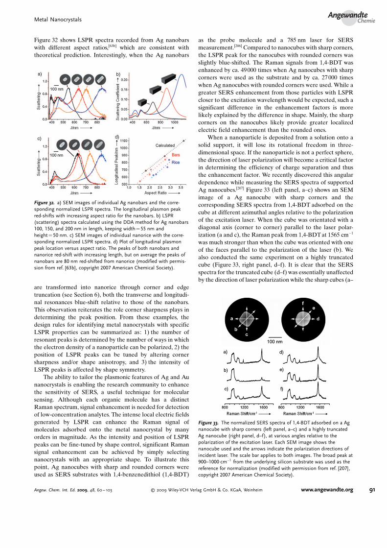
Figure 32 shows LSPR spectra recorded from Ag nanobarswith different aspect ratios,[63b] which are consistent withtheoretical prediction. Interestingly, when the Ag nanobars
are transformed into nanorice through corner and edgetruncation (see Section 6), both the transverse and longitudi-nal resonances blue-shift relative to those of the nanobars.This observation reiterates the role corner sharpness plays indetermining the peak position. From these examples, thedesign rules for identifying metal nanocrystals with specificLSPR properties can be summarized as: 1) the number ofresonant peaks is determined by the number of ways in whichthe electron density of a nanoparticle can be polarized, 2) theposition of LSPR peaks can be tuned by altering cornersharpness and/or shape anisotropy, and 3) the intensity ofLSPR peaks is affected by shape symmetry.
The ability to tailor the plasmonic features of Ag and Aunanocrystals is enabling the research community to enhancethe sensitivity of SERS, a useful technique for molecularsensing. Although each organic molecule has a distinctRaman spectrum, signal enhancement is needed for detectionof low-concentration analytes. The intense local electric fieldsgenerated by LSPR can enhance the Raman signal ofmolecules adsorbed onto the metal nanocrystal by manyorders in magnitude. As the intensity and position of LSPRpeaks can be fine-tuned by shape control, significant Ramansignal enhancement can be achieved by simply selectingnanocrystals with an appropriate shape. To illustrate thispoint, Ag nanocubes with sharp and rounded corners wereused as SERS substrates with 1,4-benzenedithiol (1,4-BDT)
as the probe molecule and a 785 nm laser for SERSmeasurement.[206] Compared to nanocubes with sharp corners,the LSPR peak for the nanocubes with rounded corners wasslightly blue-shifted. The Raman signals from 1,4-BDT wasenhanced by ca. 49000 times when Ag nanocubes with sharpcorners were used as the substrate and by ca. 27 000 timeswhen Ag nanocubes with rounded corners were used. While agreater SERS enhancement from those particles with LSPRcloser to the excitation wavelength would be expected, such asignificant difference in the enhancement factors is morelikely explained by the difference in shape. Mainly, the sharpcorners on the nanocubes likely provide greater localizedelectric field enhancement than the rounded ones.
When a nanoparticle is deposited from a solution onto asolid support, it will lose its rotational freedom in three-dimensional space. If the nanoparticle is not a perfect sphere,the direction of laser polarization will become a critical factorin determining the efficiency of charge separation and thusthe enhancement factor. We recently discovered this angulardependence while measuring the SERS spectra of supportedAg nanocubes.[207] Figure 33 (left panel, a–c) shows an SEMimage of a Ag nanocube with sharp corners and thecorresponding SERS spectra from 1,4-BDT adsorbed on thecube at different azimuthal angles relative to the polarizationof the excitation laser. When the cube was orientated with adiagonal axis (corner to corner) parallel to the laser polar-ization (a and c), the Raman peak from 1,4-BDT at 1565 cm�1
was much stronger than when the cube was oriented with oneof the faces parallel to the polarization of the laser (b). Wealso conducted the same experiment on a highly truncatedcube (Figure 33, right panel, d–f). It is clear that the SERSspectra for the truncated cube (d–f) was essentially unaffectedby the direction of laser polarization while the sharp cubes (a–
Figure 32. a) SEM images of individual Ag nanobars and the corre-sponding normalized LSPR spectra. The longitudinal plasmon peakred-shifts with increasing aspect ratio for the nanobars. b) LSPR(scattering) spectra calculated using the DDA method for Ag nanobars100, 150, and 200 nm in length, keeping width =55 nm andheight= 50 nm. c) SEM images of individual nanorice with the corre-sponding normalized LSPR spectra. d) Plot of longitudinal plasmonpeak location versus aspect ratio. The peaks of both nanobars andnanorice red-shift with increasing length, but on average the peaks ofnanobars are 80 nm red-shifted from nanorice (modified with permis-sion from ref. [63b], copyright 2007 American Chemical Society).
Figure 33. The normalized SERS spectra of 1,4-BDT adsorbed on a Agnanocube with sharp corners (left panel, a–c) and a highly truncatedAg nanocube (right panel, d–f), at various angles relative to thepolarization of the excitation laser. Each SEM image shows thenanocube used and the arrows indicate the polarization directions ofincident laser. The scale bar applies to both images. The broad peak at900–1000 cm�1 from the underlying silicon substrate was used as thereference for normalization (modified with permission from ref. [207],copyright 2007 American Chemical Society).
Metal NanocrystalsAngewandte
Chemie
91Angew. Chem. Int. Ed. 2009, 48, 60 – 103 � 2009 Wiley-VCH Verlag GmbH & Co. KGaA, Weinheim www.angewandte.org

c) showed drastic variations as their orientations werechanged. Because the nanocubes adopt random orientationswhen deposited on a substrate and the polarization of thelaser is fixed, significant variations in the SERS intensity canbe observed. These results clearly demonstrate that extracautions must be taken in order to achieve reproducible andmeaningful SERS measurements when nanoparticles areimmobilized on substrates. In general, optical studies haveto be correlated with high-resolution imaging in order to drawany conclusion about the enhancement factor.
The optimization of LSPR features through shape controlis leading to good SERS substrate design for coinage metals(Ag, Au, and Cu) and may also result in a diversification ofSERS substrate materials. For instance, the ubiquitousapplication of Pd in heterogeneous catalysis makes theextension of SERS to Pd attractive; however, the SERSenhancement factors of Pd substrates have been low due tothe absorption/scattering of light by Pd only in the UV region.Recently, we successfully prepared Pd nanocrystals with theirLSPR bands in the visible region by controlling their shapes;this achievement now enables their use as SERS sub-strates.[208] As these examples illustrate, it is critical to controlthe morphology of metal nanocrystals if Raman enhancementis to be maximized for sensing applications.
7.2. Catalytic Properties and Applications
Catalysis has long relied on noble metals to facilitate awide variety of chemical transformations.[7] On the most basiclevel, nanocrystals of noble metals are attractive for use ascatalysts because of their high surface-to-volume ratios whichcan minimize the costs associated with their usage. Suchnanocrystals have been employed to catalyze oxidation, cross-coupling, electron-transfer, and hydrogenation reactions,among others, with industrial-scale catalytic applications forspecific metals stated in Section 5. Yet, as the demands fornoble metals are increasing with the advent of emergingtechnologies like fuel cells, the need for catalysts that are bothmore active and selective is increasing.[209] Nanocatalysts withwell-controlled shapes could help meet this growing demand.
Both the reactivity and selectivity of a catalyst can betailored by controlling the shape of a nanocrystal. As a firstapproximation, shape determines which crystal facets com-prise the surface of a nanocrystal. For example, consider atetrahedron and a cube made of an fcc metal: all the exposedfacets of a tetrahedron are {111} and all the exposed facets of acube are {100}. Assuming no surface reconstructions, the {111}faces are represented by a hexagonal array of metal atomswhile the {100} faces are represented by a square array ofmetal atoms. Such a difference can give rise to differentcatalytic activity and selectivity. For example, from studieswith single crystals, the Pt(111) surface was found to be threeto seven times more active than the Pt(100) surface foraromatization reactions.[210] Also, shape determines thenumber of atoms located at the edges or corners, which canhave a profound effect on catalytic performance.[211]
Recently, El-Sayed and co-workers studied the effectshape had on the catalytic performance of Pt nanocrystals.[18a]
In one study, they considered samples of Pt tetrahedrons,cubes, and nearly spherical cuboctahedrons for the electron-transfer reaction between [Fe(CN)6]
3� and S2O32� ions to form
[Fe(CN)6]4� and S4O6
2�. From electron microscopy analysis,they estimated that for tetrahedrons, cuboctahedrons, andcubes of 5 nm in size 35%, 13 %, and 6% of the surface atoms,respectively, were located at either corners or edges. Whenused as catalysts, they found that the average rate constantincreased exponentially as the percentage of surface atoms atcorners and edges increased. In a second study, they looked atthe Suzuki cross-coupling reaction between phenylboronicacid and iodobenzene to form biphenyl.[18a] While similarshape effects were expected, they found little difference inperformance. Analysis of the catalysts after use revealed thatthe well-defined nanocrystal shapes were lost during catalysis,reiterating the need to understand effects on shape-stabilityas discussed in Section 6.
Using a similar approach, Somorjai and co-workersrecently looked at the shape effects of cubic and cuboctahe-dral Pt nanocrystals by considering the hydrogenation ofbenzene.[144a] Regardless of shape, a threefold increase inturnover rate was measured as compared to bulk singlecrystals; however, differences in selectivity were observed.Specifically, when cuboctahedrons bound by both {111} and{100} facets were used as catalysts, both cyclohexane andcyclohexene were produced. Yet, when cubic nanocrystals,bound by only {100} facets, were used as catalysts, onlycyclohexane was produced. These results are consistent withthe product selectivity obtained from bulk Pt(111) andPt(100) single crystals and illustrate how nanocrystals withwell-defined shapes can be used to improve the selectivity of acatalyst. Additionally, Somorjai and co-workers found thatfor cubic nanocrystals the apparent activation energy forcyclohexane production was 10.9� 0.4 kcalmol�1 while forcuboctahedral nanoparticles the apparent activation energiesfor cyclohexane and cyclohexene production were 8.3� 0.2and 12.2� 0.4 kcalmol�1, respectively. These activation ener-gies are significantly lower than those obtained with Pt singlecrystals, and these differences were attributed to either theincrease of corner and edge sites available for reaction or achange in the electronic structure of the Pt nanocrystals ascompared to larger single crystals.
In related work, Sun and co-workers recently consideredPt nanocubes, truncated cubes, and polyhedrons as catalystsfor the oxygen reduction reaction in a H2SO4-containingmedium.[212] They found that the measured current densitywas four times greater when Pt nanocubes were used ascompared to the systems where either polyhedral or truncatedcubic Pt nanocrystals were used. This difference in activitywas attributed to the different adsorption rates of sulfates onPt(100) and Pt(111) facets[213] and illustrates the enhancementnanocrystals of different shapes may bring to fuel cellapplications.
Given the importance of edge and corner sites to catalysis,there has been a growing interest in preparing metal nano-crystals with high-index planes that have a greater percentageof unsaturated atomic steps, edges, and kinks which can serveas intrinsically more active sites for catalysis. Fundamentalstudies on the single-crystal surfaces of bulk Pt have shown
Y. Xia et al.Reviews
92 www.angewandte.org � 2009 Wiley-VCH Verlag GmbH & Co. KGaA, Weinheim Angew. Chem. Int. Ed. 2009, 48, 60 – 103

that high-index planes exhibit much higher catalytic activitythan that of common and stable, low-index planes such as{111} and {100}.[209] As discussed in Section 5.4, Pt THHs withhigh-index {730}, {210}, and/or {520} surfaces have recentlybeen prepared, providing a unique opportunity to study theircatalytic performance.[145] In an initial study, it was found thatthe Pt THHs were up to 360 % more efficient per unit surfacearea for the electro-oxidation of ethanol and up to 200%more efficient for formic acid electro-oxidation as comparedto a commercial 3.2 nm Pt/C catalyst.
From the results discussed in this section, it becomes clearthat maximization of surface, edge, and corner sites should bethe criteria for designing superior nanocatalysts. In theselection of nanocatalysts, the stability of nanoparticles andthe capping agents on their surfaces are also worth noting. Inmany cases, the surface atoms of nanocatalysts are so activethat their size and shape change during the catalyticreaction.[18b] Such changes can drastically alter their perfor-mance and lifetime. Additionally, capping agents mightdeactivate catalytic sites, with recent work demonstratingthat Pt nanoparticles prepared with TTAB exhibit muchhigher activity than PVP-capped Pt nanocrystals.[143d] Theseissues regarding catalyst stability and poisoning will need tobe addressed for shape-controlled nanocrystals to be fullyimplemented as industrial catalysts.
7.3. Electronic Properties and Applications
As integrated circuits become smaller, the incentive toincorporate metal nanocrystals as interconnects and transportmaterials increases. In Section 5, a number of metal nano-crystals were discussed that could be attractive for use inelectronic applications. For example, Ag has the highestelectrical and thermal conductivity of any metal, making 1-DAg nanocrystals such as Ag nanowires or nanobeams (seeSection 5.2) promising nanoscale conduits for electricity orheat. In a recent study, we looked at the electrical propertiesof Ag nanobeams.[69] In particular, the resistivity and current-carrying ability were measured for a collection of nanobeamswith different lengths and widths. It was found that for ananobeam with a diameter of 20 nm the resistivity was onlytwice that of bulk silver (with the resistivity decreasing withincreasing diameter, as expected). This result illustrates thatAg nanobeams, despite their diminished sizes, largely pre-serve the unparalleled electrical conductivity of bulk Ag.Additionally, it was found that the maximum current that thenanobeams could support increased with increasing beamcross-section, with a maximum current density of ca. 1.8 �108 Acm�2 being obtained. This value is comparable to thehighest current densities reported for multi-walled carbonnanotubes (ca. 109 Acm�2).[214] While these results exemplifythe potential for nanoscale building blocks of Ag in electronicapplications, they do not reveal any shape-dependant proper-ties. As resistivity depends on the nature of electron scatterfrom the metal surface, it is possible that shape couldinfluence the conduction properties of a metal nanocrystal.Unfortunately, studies of this nature have not been con-ducted. At least, shape-controlled synthesis allows the gen-
eration of 1-D nanocrystals, to which electrodes can be easilyapplied for transport measurements.
7.4. Magnetic Properties and Applications
With their diminished sizes and single-domain magnetism,ferromagnetic nanoparticles (e.g., Co, Ni, Fe) have garnered asignificant amount of attention recently for their potential useas high-density storage media for magnetic memory devi-ces.[10] Yet, attempts to use such materials are complicated bythe so-called “superparamagnetic limit” in which the minia-turization of magnetic particles is coupled with a reduction inthe magnetic energy barrier for flipping spin orientation.[215] Itthus becomes desirable to overcome this limit as well as tounderstand the factors that govern magnetic phenomena onthe nanoscale so that such nanomaterials may be integratedappropriately. For magnetic recording media, it is advanta-geous to have high magnetizations and coercive fields whilemaintaining small particle size.
As with the other properties of metals, changing the sizeand shape of a ferromagnetic metal nanocrystal can have aprofound impact on its fundamental magnetic properties, withsuperparamagnetism representing one of the fascinating newproperties discovered by preparing these metals as nano-crystals of suitably small size.[216] In a superparamagneticcrystal, the thermal energy (kT) is sufficient to switch themagnetic spin direction (i.e., from a spin-up to a spin-downstate), resulting in a net magnetization of zero. The transitiontemperature from ferromagnetism to superparamagnetism(i.e., the blocking temperature, Tb) is dependant on the size ofthe nanocrystal according to Equation (4) where Ku is themagnetic anisotropic constant and V is the volume of thenanocrystal.[217]
Tb ¼ Ku V=25 k ð4Þ
Thus, it is expected that as the size of a nanocrystaldecreases, the ferromagnetic-to-superparamagnetic transitionwill occur at increasingly lower temperatures. Using a super-conducting quantum interference device (SQUID), Cheonand co-workers validated this relationship by analyzing thesize-dependent magnetic properties of monodisperse Conanocrystals similar to those discussed in Section 5.7.[218] Asexpected, the Tb was found to gradually increase withincreasing nanocrystal size, with Tb>RT for particles withdiameters > 10.3 nm only. Additionally, magnetic coercivity(Hc) is affected by nanocrystal size. Outside of the super-paramagnetic regime where Hc is zero, sufficiently smallnanocrystals still possess a single magnetic domain in whichall magnetic spins can align unidirectionally. Within thisregime, the magnetic coercivity increases with increasingnanocrystal size according to Equation (5) where ms is thesaturation magnetization value.[217]
Hc ¼ 2 Ku=ms½1�5ðkT=KuVÞ1=2� ð5Þ
It is important to note that above a critical nanocrystalsize this trend breaks down due to the formation of multiple
Metal NanocrystalsAngewandte
Chemie
93Angew. Chem. Int. Ed. 2009, 48, 60 – 103 � 2009 Wiley-VCH Verlag GmbH & Co. KGaA, Weinheim www.angewandte.org

magnetic domains. Cheon and co-workers also validated thisrelationship using monodisperse Co nanoparticles, and asexpected, Hc was found to increase with increasing size withinthe single magnetic domain regime.[219]
These trends illustrate the potential limitations of ferro-magnetic nanoparticles for magnetic storage media; however,it has been found that within the single magnetic domainregime, both Tb and Hc are dependent on the shape of amagnetic nanocrystal, providing a potentially powerful way totune the properties of a magnetic nanoparticle. Specifically,Ku is no longer constant and varies with anisotropies in shape.This relationship can be expressed as Equation (6) where Ha
is the anisotropy field, N1 and N2 are the shape-dependentdemagnetization factors parallel and perpendicular to theeasy axis of the magnetic nanocrystal, and Ms is the saturationmagnetization of bulk materials.[217]
Ku ¼ ½Ha þ ðN1�N2ÞMs�Ms=2 ð6Þ
Shape effects have been studied most extensively in Conanorods and nanowires prepared either by electrodepositionor template methods.[220] For example, Co nanorods of threelengths (14, 3.8, and 0.75 mm) were prepared while keepingthe diameter constant.[220a] Hysteresis curve measurements at300 K with the sample held perpendicular to the applied field(the easy axis of magnetization is along the axis of thesenanorods) showed that the saturation magnetizationincreased, with greatly enhanced coercivities, as the nanorodlength increased. This trend was attributed to an increase inKu. Interestingly, recent studies have shown that the easy axisof magnetization for Co nanorods can be reoriented perpen-dicular to the long axis of the rod and that this reorientationcan lead to drastic changes in the overall magnetic aniso-tropy.[220c]
Presumably, analogous materials prepared by wet-chem-ical methods would display similar effects, pending anyanomalous surface capping effects from surfactants;[174a]
however, such extensive work has not been done. As onepromising example, Cheon and co-workers evaluated themagnetic properties of Co nanorods (4 � 20 nm) and com-pared them to Co nanospheres (diameter 4 nm).[219] Theyfound that the Tb of the Co nanorods exceeded 360 K(compared to 20 K for the nanospheres). For the low temper-ature (5 K) hysteresis curve measurements, the nanorodsshowed a larger Hc than the nanospheres: 460 versus 370 Oe(Oersted; unit of magnetic field strength). At room temper-ature, the nanorods maintained an Hc of ca. 35 Oe. In relatedwork, it was recently shown that triangular and hexagonal Niplates such as those discussed in Section 5.7 display signifi-cantly higher coercivity as compared to other Ni nano-structures, and this enhancement was attributed to theincrease in anisotropic energy due to their unique 2-Dstructure.[221] It is anticipated that suitable magnetic nano-crystals with narrow size distribution (< 5%) will be self-assembled into ordered arrays with controlled magneticalignment so to achieve high-density information storage.
7.5. Nanocrystals as Building Blocks for Self-Assembly
Self-assembly provides an effective route to well-definedstructures that are close to or at a thermodynamic equilibriumstate.[222] The essence of self-assembly is that pre-designedbuilding blocks spontaneously organize themselves into arelatively stable structure through non-covalent interactions.The final structure is determined by the characteristics of thebuilding blocks, as the information that defines a self-assembly process (and thus the final structure) is oftenencoded into the building blocks in the form of shape and/orsurface functionality. Nanocrystals are ideal building blocksfor self-assembly, which can be potentially employed tofabricate functional devices and complex systems. Signifi-cantly, the shape of nanocrystals can provide a useful knob forcontrolling the self-assembled structures.[178d, 222–225] Forinstance, nanorods tend to form liquid crystalline phases,while nanospheres and nanocubes tend to form long-rangeordered lattices. As limited by space, here we only illustratetwo examples from our group.
As discussed in Section 5.8, metals with low melting points(e.g., Bi and Pb) can be easily processed as monodispersedcolloidal spheres with diameters in the range of 100–600 nmand size variations well below 5%. These metal nanospherescould be further coated with uniform, conformal shells madeof a dielectric material such as silica. Because of theirspherical shape and uniform size, the as-synthesized spheresself-assembled into 3-D metallodielectric photonic crys-tals.[178d] As shown by computational studies, crystallinelattices consisting of metal spheres or dielectric-coatedmetal spheres may exhibit complete photonic band gapsextending over the entire optical regime. Figure 34 shows thereflectance spectra taken from two typical crystals obtainedfrom Pb and Pb@SiO2 colloidal spheres, and their corre-sponding top-view SEM images are shown as the insets. Bothcrystals have an fcc structure with their (111) planes orientedparallel to the surfaces of the supporting substrates. A strongreflection band at 775 nm was observed for the crystals basedon Pb colloidal spheres, while the Pb@SiO2 crystals displayedadditional peaks at 415 and 530 nm in the visible region.These results suggest that large photonic band gaps could beobtained from this system to cover optical wavelengths fromthe visible up to the near infrared region.
In a recent study, we demonstrated the self-assembly ofAg nanocubes into specific structures by modifying their sidefaces with hydrophobic and hydrophilic self-assembled mon-olayers (SAMs).[226] In terms of monodispersity and avail-ability, Ag nanocubes are unrivaled as a new class of buildingblocks for self-assembly. The nanocube itself has a non-spherical shape, and significantly, one can control thestructures of resultant assemblies by functionalizing the sixfaces of a nanocube with hydrophobic and hydrophilic SAMsin different schemes. When one side of each cube isfunctionalized with a hydrophobic, octadecanethiol (ODT)SAM and all others are functionalized with a hydrophilic,mercaptohexadecanoic acid (MHA) SAM, the nanocubestended to form dimers, as shown in Figure 35 a. When twoopposing faces of each cube were functionalized with theODT and the remaining four faces with the MHA, linear
Y. Xia et al.Reviews
94 www.angewandte.org � 2009 Wiley-VCH Verlag GmbH & Co. KGaA, Weinheim Angew. Chem. Int. Ed. 2009, 48, 60 – 103

chains of three or more cubes could be readily found duringSEM characterization (Figure 35 b). When the Ag nanocubeswere functionalized in an inverse manner, such that four oftheir sides were modified with ODT and the other two weremodified with an MHA, they tended to form 2-D sheets asshown in Figure 35c. These sheets were typically square orrectangular with lengths of 500 nm and had a structure similarto computer simulations of nanocubes with strong face-to-
face interactions. When the entire surface of each Agnanocube was covered by ODT, the building blocks werehydrophobic and aggregated shortly after being dispersedinto water. The formed structures are shown in Figure 35d: a3-D lattice of the Ag nanocubes. Over time the size of thesestructures appeared to grow but ultimately plateaued at1.2 mm in length (ten to twelve nanocubes along the edge).The cubic nature of the final structures suggests that theassembly occurred equally in all three dimensions
8. Summary and Outlook
The last decade has witnessed significant progress in theshape-controlled synthesis of metal nanocrystals. Thanks tothe efforts of many research groups, a rich variety ofnanocrystal shapes have been achieved for a large numberof different metals (Table 1). Controlling the shape of ananocrystal may initially seem like a scientific curiosity, but itsgoal goes far beyond aesthetic appeal. As showcased inSection 7, the shape of a metal nanocrystal determines notonly its intrinsic physical and chemical properties but also itsrelevance for optical, catalytic, electronic, and magneticapplications. In discussing the various systems, we strived toelaborate on the plausible nucleation and growth mechanismsinvolved; however, a quantitative description of crystalnucleation and growth is still challenging. For example,there is little knowledge of the actual nature of the nucleiinvolved in the formation of nanocrystals. Such informationwould be invaluable in correlating experimental results withsynthetic conditions. Additionally, there is no conclusiveaccount of the roles played by solvent molecules, cappingagents, and the trace impurities present in all commercialchemical reagents. Yet, as illustrated in Section 5, all of thesespecies influence the outcome of a synthesis. Because of theseunanswered questions, what is presented in this Reviewshould be considered as a collection of protocols, workinghypotheses, and guiding principles for generating metalnanocrystals of different shapes. We hope that these protocolsand rules can serve as a valuable resource, allowing theproduction of metal nanocrystals with specific propertiessought for applications in the areas of electronics, photonics,catalysis, information storage, sensing, imaging, and biomed-ical research. It cannot be overemphasized though that mostof the conclusions drawn about metal nanocrystal synthesesare to be challenged and refined as our understanding of thenucleation and growth mechanisms is advanced.
Why is it so difficult to decipher the secrets that lead to theformation of nanocrystals with a specific shape? There is nosimple answer to this question. Based on our experience,however, we believe it can be addressed from the followingaspects:a) We should never overlook the seemingly simple reaction
involved in a chemical synthesis. For example, it has beenassumed that in a typical polyol synthesis, acetaldehyde,derived from the dehydration of ethylene glycol, was thereductant. Our most recent results, however, indicate thatat least for Ag and in the temperature range of 140 to160 8C, the primary reductant is glycolaldehyde, being
Figure 34. Reflectance spectra obtained from crystalline lattices ofa) Pb and b) Pb@SiO2 nanospheres with the incident light orientedperpendicular to their (111) planes. The insets in both figures showthe corresponding top-view SEM images for the two crystalline lattices.Both scale bars in the insets are 200 nm (modified with permissionfrom ref. [178d], copyright 2006 Wiley-VCH).
Figure 35. SEM images of structures self-assembled from Ag nano-cubes. The nanocubes were selectively functionalized with hydrophilicand hydrophobic thiolate SAMs and then allowed to assemble inwater. The number of faces on each nanocube that were renderedhydrophobic is indicated in grey color in the bottom right corner ofeach panel, the remaining faces on the nanocube were hydrophilic. Allnanocubes used in this study had a mean edge length of 97�6 nm, asdetermined from 123 cubes (modified with permission from ref. [226],copyright 2008 Wiley-VCH).
Metal NanocrystalsAngewandte
Chemie
95Angew. Chem. Int. Ed. 2009, 48, 60 – 103 � 2009 Wiley-VCH Verlag GmbH & Co. KGaA, Weinheim www.angewandte.org

produced via thermal oxidation of ethylene glycol by theoxygen in air.[227] With this new reaction pathway identi-fied, it now becomes possible to explain many exper-imental observations that were poorly understood pre-viously. Notable examples include the influence of reac-tion temperature, ionic impurities, and reaction environ-ment. In another example, Brus and co-workers recentlyfound that citrate, a stabilizer commonly used in thesynthesis of Ag nanoplates, was directly consumed as thereaction proceeded.[228] They proposed a new mechanismthat involves the coupling between oxidative etching ofthe seed and subsequent photoreduction of aqueous Ag+
ions. The reduced Ag deposits onto a Ag nanoplate ofspecific size that has a cathodic photovoltage resultingfrom plasmon “hot hole” citrate photo-oxidation. In thefuture, one should consider all possible reaction pathwaysfor the reduction or decomposition of a precursor. Then,through the identification of reaction intermediates orbyproducts, it should be possible to identify with certaintywhich reagents or experimental parameters play pivotalroles in controlling the reduction kinetics, and thus thenucleation and growth pathway.
b) We should never underestimate the roles of trace amountsof impurities that are present in commercial chemicalreagents. For production and storage reasons, essentiallyall chemical reagents are contaminated with certainamounts of known or unknown impurities. As we haveshown for the polyol synthesis of Ag nanocrystals, eventhe presence of a ppm level of Fe2+, Fe3+, or Cl� impuritycan drastically alter the morphology of the final product.This high level of sensitivity might help explain many ofthe mysteries as well as the irreproducible results asso-ciated with shape-controlled syntheses of metal nano-crystals. In many cases, the unexpected effects of animpurity can be greatly amplified due to the autocatalyticnature of nanocrystal growth. Also, it should be noted thatthe effects of an impurity in one system could differgreatly when transferred to another system (e.g., iron saltsin the Ag and Pt systems).
c) We need to pay closer attention to the chemical compo-sition of a reaction system. This need is particularlyimportant for metals like Ag and Au because most of theirsalt precursors (e.g., AgNO3 and AuCl) are sensitive tolight. As we have shown for AgNO3, a freshly preparedaqueous solution of this salt can contain a significantamount of trimeric clusters. Due to the autocatalyticnature of metal nanocrystal growth, the presence of suchclusters can drastically change the reduction kinetics andreaction pathway, and thus the shape of the final product.
d) We need to pay closer attention to the gaseous speciesfrom air (including O2, N2, CO, and water vapor) andreaction by-products. These species may influence boththe reduction kinetics of a precursor and the growth ratesof different crystallographic planes. For example, both O2
and CO (a common product of Pt-catalyzed decomposi-tion of an organic species) have been shown to playimportant roles in influencing the morphology of Ptnanocrystals due to chemisorption. Unfortunately, their
presence and potential roles have been largely ignored inprevious studies.
e) We need to pay closer attention to H+ and OH� , twospecies commonly associated with a redox reactionwhenever water is involved. These two species mighthave strong affinity towards specific crystal facets—forexample, H+ for the {100} facets of Ag, Au, Pd, and Pt—which could contribute to shape control.
It should be pointed out that most of the availablestrategies for shape-controlled synthesis are built uponmanipulation of the growth processes rather than nucleation.This observation is likely because very little is known aboutthe nucleation process. To address this long-standing, funda-mental problem in chemistry and physics, tools capable ofcapturing, identifying, and quantifying the nuclei are badlyneeded. Parallel to this advancement, computational methodsneed to proceed so that an atomistic-level understanding ofthe elementary steps involved in a nucleation process can beachieved. Molecular dynamic (MD) simulations are well-suited for this purpose. With little or no a priori knowledgeabout the specific agglomeration reactions, ab initio MDsimulations provide a useful tool for reaction sampling oridentification of the key reaction conditions that controlnucleus formation, a starting point for calculating the energybarriers and reaction rates of different pathways. An integra-tion of experimental studies and theoretical modeling willgreatly advance our understanding of nucleation and shouldoffer new methods for controlling the assembly of atoms intoclusters and then nanocrystals with specific shapes. From suchwork, the design rules for producing metal nanocrystals (aswell as for other types of solid materials) with exact shapeswill be developed. Only at that point, we will have a scientificbasis for manufacturing nanocrystals with specific electronic,photonic, magnetic, and catalytic properties sought for abroad range of applications.
This work was supported in part by research grants from NSF(DMR-0804088 and DMR-0451788), ACS (PRF-44353-AC10), and ONR (N-00014-01-1-0976); a CAREER Awardfrom NSF (DMR-9983893); a DARPA-DURINT subcontractfrom Harvard University; an AFOSR-DURINT subcontractfrom SUNY Buffalo; a MRSEC subcontract from the NSF-funded GEMSEC program at the UW; and a 2006 Director�sPioneer Award from NIH (5DP1D000798). Y.X. was aCamille Dreyfus Teacher Scholar, an Alfred P. Sloan ResearchFellow, and a David and Lucile Packard Fellow in Science andEngineering. B.L. was also partially supported by the Post-doctoral Fellowship Program of the Korea Research Founda-tion (KRF).
Received: May 14, 2008Published online: December 3, 2008
[1] B. D. Fahlman, Materials Chemistry, Vol. 1, Springer, MountPleasant, 2007, pp. 282 – 283.
[2] See, for example, a) W. P. Halperin, Rev. Mod. Phys. 1986, 58,533; b) U. Kreibig, M. Vollmer, Optical Properties of Metal
Y. Xia et al.Reviews
96 www.angewandte.org � 2009 Wiley-VCH Verlag GmbH & Co. KGaA, Weinheim Angew. Chem. Int. Ed. 2009, 48, 60 – 103

Clusters, Springer, New York, 1995 ; c) http://esi-topics.com/nanocrystals/.
[3] Reviews: a) M. G. Bawendi, M. L. Steigerwald, L. E. Brus,Annu. Rev. Phys. Chem. 1990, 41, 477; b) H. Weller, Adv. Mater.1993, 5, 88; c) A. P. Alivisatos, Science 1996, 271, 933; d) C. B.Murray, C. R. Kagan, M. G. Bawendi, Annu. Rev. Mater. Sci.2000, 30, 545.
[4] See, for example, a) K. K. Likharev, IBM J. Res. Dev. 1988, 32,144; b) V. Maheshwari, J. Kane, R. Saraf, Adv. Mater. 2008, 20,284.
[5] See, for example, a) N. F. Mott, Rev. Mod. Phys. 1968, 40, 677;b) G. Markovich, C. P. Collier, S. E. Henrichs, F. Remacle, R. D.Levine, J. R. Heath, Acc. Chem. Res. 1999, 32, 415.
[6] Reviews: a) T. Hyeon, Chem. Commun. 2003, 927; b) S. Sun,Adv. Mater. 2006, 18, 393; c) U. Jeong, X. Teng, Y. Wang, H.Yang, Y. Xia, Adv. Mater. 2007, 19, 33.
[7] a) L. N. Lewis, Chem. Rev. 1993, 93, 2693; b) G. A. Somorjai,Chem. Rev. 1996, 96, 1223; c) G. Ertl, Handbook of Heteroge-neous Catalysis, Wiley-VCH, Weinheim, 2008.
[8] See, for example, a) N. M. Davey, R. J. Seymour, Platinum Met.Rev. 1985, 29, 2; b) S. Jeong, K. Woo, D. Kim, S. Lim, J. S. Kim,H. Shin, Y. Xia, J. Moon, Adv. Funct. Mater. 2008, 18, 679.
[9] See, for example, a) J. F. Hamilton, Adv. Phys. 1988, 37, 359;b) T. Tani, Phys. Today 1989, 42, 36.
[10] Reviews: a) A special issue on magnetic recording materials inMRS Bull., 1990, 15, 12; b) C. B. Murray, S. Sun, H. Doyle, T.Betley, MRS Bull. 2001, 26, 985.
[11] See, for example, a) A. C. Templeton, W. P. Wuelfing, R. W.Murray, Acc. Chem. Res. 2000, 33, 27; b) S. R. Nicewarner-Pe�a, R. G. Freeman, B. D. Reiss, L. He, D. J. Pe�a, I. D.Walton, R. Cromer, C. D. Keating, M. J. Natan, Science 2001,294, 137.
[12] See, for example, a) S. A. Maier, M. L. Brongersma, P. G. Kik,S. Meltzer, A. A. G. Requicha, H. A. Atwater, Adv. Mater.2001, 13, 1501; b) A. W. Sanders, D. A. Routenberg, B. J. Wiley,Y. Xia, E. R. Dufresne, M. A. Reed, Nano Lett. 2006, 6, 1822.
[13] a) T. A. Taton, C. A. Mirkin, R. L. Letsinger, Science 2000, 289,1757; b) A. G. Tkachenko, H. Xie, D. Coleman, W. Glomm, J.Ryan, M. F. Anderson, S. Franzen, D. L. Feldheim, J. Am.Chem. Soc. 2003, 125, 4700; c) X. Zhang, M. A. Young, O.Lyandres, R. P. Van Duyne, J. Am. Chem. Soc. 2005, 127, 4484;d) M. M.-C. Cheng, G. Cuda, Y. L. Bunimovich, M. Gaspari,J. R. Heath, H. D. Hill, C. A. Mirkin, A. J. Nijdam, R.Terracciano, T. Thundat, M. Ferrari, Curr. Opin. Chem. Biol.2006, 10, 11; e) H. Wang, D. W. Brandl, P. Nordlander, N. J.Halas, Acc. Chem. Res. 2007, 40, 53.
[14] See, for example, a) J. Chen, F. Saeki, B. J. Wiley, H. Cang, M. J.Cobb, Z.-Y. Li, L. Au, H. Zhang, M. B. Kimmey, X. Li, Y. Xia,Nano Lett. 2005, 5, 473; b) H. Cang, T. Sun, Z.-Y. Li, J. Chen,B. J. Wiley, Y. Xia, X. Li, Opt. Lett. 2005, 30, 3048; c) X. Yang,S. E. Skrabalak, Z.-Y. Li, Y. Xia, L. V. Wang, Nano Lett. 2007, 7,3798.
[15] Reviews: a) J. L. West, N. J. Halas, Annu. Rev. Biomed. Eng.2003, 5, 285; b) P. K. Jain, I. H. El-Sayed, M. A. El-Sayed, NanoToday 2007, 2, 18; c) S. E. Skrabalak, J. Chen, L. Au, X. Lu, X.Li, Y. Xia, Adv. Mater. 2007, 19, 3177; d) S. E. Skrabalak, L. Au,X. Lu, X. Li, Y. Xia, Nanomedicine 2007, 2, 657; e) P. Fortina,L. J. Kricka, D. J. Graves, J. Park, T. Hyslop, F. Tam, N. Halas, S.Surrey, S. A. Waldman, Trends Biotechnol. 2007, 25, 145;f) P. K. Jain, X. Huang, I. H. El-Sayed, M. A. El-Sayed, Acc.Chem. Res. 2008, DOI: 10.1021/ar7002804; g) L. Au, D. Zheng,F. Zhou, Z.-Y. Li, X. Li, Y. Xia, ACS Nano 2008, 2, 1645.
[16] a) T. R. Jensen, L. Kelly, A. Lazarides, G. C. Schatz, J. ClusterSci. 1999, 10, 295; b) J. P. Kottmann, O. J. F. Martin, D. R.Smith, S. Schultz, Phys. Rev. B 2001, 64, 235402; c) M. A. El-Sayed, Acc. Chem. Res. 2001, 34, 257; d) I. O. Sosa, C. Noguez,R. G. Barrera, J. Phys. Chem. B 2003, 107, 6269; e) B. J. Wiley,
S. H. Im, Z.-Y. Li, J. M. McLellan, A. Siekkinen, Y. Xia, J. Phys.Chem. B 2006, 110, 15666.
[17] See, for example, a) M. Haruta, Catal. Today 1997, 36, 153;b) M. Valden, X. Lai, D. W. Goodman, Science 1998, 281, 1647;c) C. T. Campbell, S. C. Parker, D. E. Starr, Science 2002, 298,811.
[18] a) R. Narayanan, M. A. El-Sayed, J. Phys. Chem. B 2005, 109,12663; b) A. Zecchina, E. Groppo, S. Bordiga, Chem. Eur. J.2007, 13, 2440.
[19] a) L. M. Falicov, G. A. Somorjai, Proc. Natl. Acad. Sci. USA1985, 82, 2207; b) A.-C. Shi, R. I. Masel, J. Catal. 1989, 120, 421.
[20] a) G. Wulff, Z. Kristallogr. 1901, 34, 449; b) L. D. Marks, Rep.Prog. Phys. 1994, 57, 603; c) A. Pimpinelli, J. Villain, Physics ofCrystal Growth, Cambridge University Press, Cambridge, 1998.
[21] J. A. Venables, Introduction to Surface and Thin Film Processes,Cambridge University Press, Cambridge, 2000, pp. 9 – 11.
[22] a) M. Faraday, Philos. Trans. R. Soc. London 1857, 147, 145;b) P. P. Edwards, J. M. Thomas, Angew. Chem. 2007, 119, 5576;Angew. Chem. Int. Ed. 2007, 46, 5480.
[23] a) A. Henglein, Chem. Rev. 1989, 89, 1861; b) J. H. Fendler,Adv. Mater. 1995, 7, 607; c) G. Schmid, L. F. Chi, Adv. Mater.1998, 10, 515; d) S. Link, M. A. El-Sayed, J. Phys. Chem. B1999, 103, 8410.
[24] a) B. Wiley, Y. Sun, B. Mayers, Y. Xia, Chem. Eur. J. 2005, 11,454; b) B. Wiley, Y. Sun, J. Chen, H. Cang, Z.-Y. Li, X. Li, Y.Xia, MRS Bull. 2005, 30, 356; c) B. Wiley, Y. Sun, Y. Xia, Acc.Chem. Res. 2007, 40, 1067; d) A. R. Tao, S. Habas, P. Yang,Small 2008, 4, 310.
[25] a) C. J. Murphy, N. R. Jana, Adv. Mater. 2002, 14, 80; b) C. J.Murphy, T. K. Sau, A. M. Gole, C. J. Orendorff, J. Gao, L. Gao,S. E. Hunyadi, T. Li, J. Phys. Chem. B 2005, 109, 13857; c) C. J.Murphy, A. M. Gole, S. E. Hunyadi, C. J. Orendorff, Inorg.Chem. 2006, 45, 7544.
[26] Y. Xiong, Y. Xia, Adv. Mater. 2007, 19, 3385.[27] D. W. Oxtoby, Nature 2000, 406, 464.[28] S. Auer, D. Frenkel, Nature 2001, 409, 1020.[29] U. Gasser, E. R. Weeks, A. Schofield, P. N. Pusey, D. A. Weitz,
Science 2001, 292, 258.[30] a) A. C. Hillier, M. D. Ward, Science 1994, 263, 1261; b) Z.
Zhang, M. G. Lagally, Science 1997, 276, 377; c) H. Bruce, M.Giovannini, K. Bromann, K. Kern, Nature 1998, 394, 451; d) S.-T. Yau, P. G. Vekilov, Nature 2000, 406, 494.
[31] a) S. M. Lee, W. T. Wong, J. Cluster Sci. 1998, 9, 417; b) M. G.Richmond, Coord. Chem. Rev. 2003, 241, 273.
[32] a) H. W. Roesky, S. Singh, K. K. M. Yusuff, J. A. Maguire, N. S.Hosmane, Chem. Rev. 2006, 106, 3813; b) M. Melnik, I.Ondrejkovicova, D. Miklos, P. Segla, C. E. Holloway, Rev.Inorg. Chem. 2007, 27, 67; c) Y. Sevryugina, A. Y. Rogachev,M. A. Petrukhina, Inorg. Chem. 2007, 46, 7870; d) J. Hartig, A.St�ßer, P. Hauser, H. Schn�ckel, Angew. Chem. 2007, 119, 1687;Angew. Chem. Int. Ed. 2007, 46, 1658; e) C. E. Anson, A.Eichh�fer, I. Issac, D. Fenske, O. Fuhr, P. Sevillano, C. Persau,D. Stalke, J. Zhang, Angew. Chem. 2008, 120, 1346; Angew.Chem. Int. Ed. 2008, 47, 1326.
[33] V. K. LaMer, R. H. Dinegar, J. Am. Chem. Soc. 1950, 72, 4847.[34] M. A. Watzky, R. G. Finke, J. Am. Chem. Soc. 1997, 119, 10382.[35] a) L. C. Ciacchi, M. Mertig, W. Pompe, S. Meriani, A. De Vita,
Platinum Met. Rev. 2003, 47, 98; b) L. Colombi Ciacchi, W.Pompe, A. De Vita, J. Am. Chem. Soc. 2001, 123, 7371; c) M.Mertig, L. Colombi Ciacchi, R. Seidel, W. Pompe, A. De Vita,Nano Lett. 2002, 2, 841; d) L. Colombi Ciacchi, W. Pompe, A.De Vita, J. Phys. Chem. B 2003, 107, 1755.
[36] a) Z.-Y. Huang, G. Mills, B. Hajek, J. Phys. Chem. 1993, 97,11542; b) L. C. Ciacchi, M. Mertig, R. Seidel, W. Pompe, A.De Vita, Nanotechnology 2003, 14, 840; c) E. E. Finney, R. G.Finke, J. Colloid Interface Sci. 2008, 317, 351.
Metal NanocrystalsAngewandte
Chemie
97Angew. Chem. Int. Ed. 2009, 48, 60 – 103 � 2009 Wiley-VCH Verlag GmbH & Co. KGaA, Weinheim www.angewandte.org

[37] Y. Xiong, I. Washio, J. Chen, M. Sadilek, Y. Xia, Angew. Chem.2007, 119, 5005; Angew. Chem. Int. Ed. 2007, 46, 4917.
[38] a) J. W. Mitchell, Imaging Sci. J. 1997, 45, 2; b) D. M.-K. Lam,B. W. Rossiter, Sci. Am. 1991, 265, 80.
[39] a) J. Flad, G. Igel-Mann, H. Preuss, H. Stoll, Chem. Phys. 1984,90, 257; b) P. Y. Cheng, M. A. Duncan, Chem. Phys. Lett. 1988,152, 341; c) K. Balasubramanian, P. Y. Feng, Chem. Phys. Lett.1989, 159, 452; d) H. Partridge, C. W. Bauschlicher, Jr., S. R.Langhoff, Chem. Phys. Lett. 1990, 175, 531.
[40] a) D. W. Boo, Y. Ozaki, L. H. Andersen, W. C. Lineberger, J.Phys. Chem. A 1997, 101, 6688; b) T. Leisner, S. Vajda, S. Wolf,L. W�ste, J. Chem. Phys. 1999, 111, 1017; c) M. Hartmann, A.Heidenreich, J. Pittner, V. Bonacic-Koutecky, J. Jortner, J. Phys.Chem. A 1998, 102, 4069.
[41] P. Fayet, F. Granzer, G. Hegenbart, E. Meisar, B. Pischel, L.W�ste, Phys. Rev. Lett. 1985, 55, 3002.
[42] a) S. K�ki, L. Nagy, G. De�k, M. Zsuga, L. Somogyi, A. L�vai, J.Am. Soc. Mass Spectrom. 2004, 15, 879; b) J. A. McLean, K. A.Stumpo, D. H. Russell, J. Am. Chem. Soc. 2005, 127, 5304.
[43] X. Li, A. E. Kuznetsov, H. F. Zhang, A. I. Boldyrev, L. S. Wang,Science 2001, 291, 859.
[44] a) J. Li, X. Li, H.-J. Zhai, L. S. Wang, Science 2003, 299, 864;b) H. F. Zhang, M. Stender, R. Zhang, C. M. Wang, J. Li, L. S.Wang, J. Phys. Chem. B 2004, 108, 12259.
[45] a) L. A. Peyser, A. E. Vinson, A. P. Bartko, R. M. Dickson,Science 2001, 291, 103; b) J. Zheng, R. M. Dickson, J. Am.Chem. Soc. 2002, 124, 13982; c) J. T. Petty, J. Zheng, N. V. Hud,R. M. Dickson, J. Am. Chem. Soc. 2004, 126, 5207.
[46] a) A. Henglein, Chem. Phys. Lett. 1989, 154, 473; b) T. Linnert,P. Mulvaney, A. Henglein, H. Weller, J. Am. Chem. Soc. 1990,112, 4657; c) B. G. Ershov, E. Janata, A. Henglein, J. Phys.Chem. 1993, 97, 339.
[47] a) L. K�nig, I. Rabin, W. Schultze, G. Ertl, Science 1996, 274,1353; b) C. F�lix, C. Sieber, W. Harbich, J. Buttet, I. Rabin, W.Schultze, G. Ertl, Phys. Rev. Lett. 2001, 86, 2992; c) Y.Watanabe, G. Namikawa, T. Onuki, K. Nishio, T. Tsuchiya,Appl. Phys. Lett. 2001, 78, 2125; d) I. Belharouak, F. Weill, C.Parent, G. Le Flem, B. Moine, J. Non-Cryst. Solids 2001, 293–295, 649; e) A. V. Podlipensky, V. Grebenev, G. Seifert, H.Graener, J. Lumin. 2004, 109, 135; f) M. Treguer, F. Rocco, G.Lelong, A. L. Nestour, T. Cardinal, A. Maali, B. Lounis, SolidState Sci. 2005, 7, 812.
[48] L. Qu, W. W. Yu, X. Peng, Nano Lett. 2004, 4, 465.[49] a) G. Schmid, Chem. Rev. 1992, 92, 1709; b) D. A. van Leeu-
wen, J. M. van Ruitenbeek, G. Schmid, L. J. de Jongh, Phys.Lett. A 1992, 170, 325; c) J. D. Aiken III, R. G. Finke, J. Mol.Catal. A 1999, 145, 1; d) H. Zhang, G. Schmid, U. Hartmann,Nano Lett. 2003, 3, 305.
[50] a) Z. L. Wang, J. Phys. Chem. B 2000, 104, 1153; b) J. M. Zhang,F. Ma, K. W. Xu, Appl. Surf. Sci. 2004, 229, 34.
[51] a) D. J. Smith, A. K. Petford-Long, L. R. Wallenberg, J. O.Bovin, Science 1986, 233, 872; b) S. Iijima, T. Ichihashi, Phys.Rev. Lett. 1986, L56, 616; c) N. Doraiswamy, L. D. Marks, Surf.Sci. 1996, 348, 67; d) M. J. Yacaman, J. A. Ascencio, H. B. Liu, J.Gardea-Torresdey, J. Vac. Sci. Technol. B 2001, 19, 1091;e) H. B. Liu, J. A. Ascencio, M. Perez-Alvarez, M. J. Yacaman,Surf. Sci. 2001, 491, 88.
[52] a) P. L. Gai, M. A. Harmer, Nano Lett. 2002, 2, 771; b) C.Lofton, W. Sigmund, Adv. Funct. Mater. 2005, 15, 1197; c) J. L.Elechiguerra, J. Reyes-Gasga, M. J. Yacaman, J. Mater. Chem.2006, 16, 3906.
[53] a) H. Hofmeister, S. A. Nepijko, D. N. Levlev, W. Schulze, G.Ertl, J. Cryst. Growth 2002, 234, 773; b) S. A. Nepijko, D. N.Levlev, W. Schulze, J. Urban, G. Ertl, ChemPhysChem 2000, 1,140.
[54] a) F. Baletto, R. Ferrando, Phys. Rev. B 2001, 63, 155408; b) F.Baletto, R. Ferrando, A. Fortunelli, F. Montalenti, C. Mottet, J.
Chem. Phys. 2002, 116, 3856; c) F. Baletto, R. Ferrando, Rev.Mod. Phys. 2005, 77, 371.
[55] P. M. Ajayan, L. D. Marks, Phys. Rev. Lett. 1998, 80, 585.[56] C. Cleveland, U. Landman, J. Chem. Phys. 1991, 94, 7376.[57] a) A. I. Kirkland, D. A. Jefferson, D. G. Duff, P. P. Edwards, I.
Gameson, B. F. G. Johnson, D. J. Smith, Proc. R. Soc. LondonSer. A 1993, 440, 589; b) V. Germain, J. Li, D. Ingert, Z. L.Wang, M. P. Pileni, J. Phys. Chem. B 2003, 107, 8717.
[58] a) P.-F. Ho, K.-M. Chi, Nanotechnology 2004, 15, 1059; b) Y.Xiong, A. R. Siekkinen, J. Wang, Y. Yin, M. J. Kim, Y. Xia, J.Mater. Chem. 2007, 17, 2600.
[59] a) I. Washio, Y. Xiong, Y. Yin, Y. Xia, Adv. Mater. 2006, 18,1745; b) Y. Xiong, I. Washio, J. Chen, H. Cai, Z.-Y. Li, Y. Xia,Langmuir 2006, 22, 8563; c) B. Lim, P. H. C. Camargo, Y. Xia,Langmuir 2008, 24, 10437.
[60] Y. Xiong, J. M. McLellan, J. Chen, Y. Yin, Z.-Y. Li, Y. Xia, J.Am. Chem. Soc. 2005, 127, 17118.
[61] a) Y. Sun, Y. Xia, Adv. Mater. 2003, 15, 695; b) Y. Sun, B.Mayers, Y. Xia, Nano Lett. 2003, 3, 675.
[62] B. Wiley, T. Herricks, Y. Sun, Y. Xia, Nano Lett. 2004, 4, 1733.[63] a) B. J. Wiley, Y. Xiong, Z.-Y. Li, Y. Yin, Y. Xia, Nano Lett.
2006, 6, 765; b) B. J. Wiley, Y. Chen, J. McLellan, Y. Xiong, Z.-Y. Li, D. Ginger, Y. Xia, Nano Lett. 2007, 7, 1032.
[64] a) Y. Xiong, J. Chen, B. Wiley, Y. Xia, S. Aloni, Y. Yin, J. Am.Chem. Soc. 2005, 127, 7332; b) Y. Xiong, B. Wiley, J. Chen, Z.-Y.Li, Y. Yin, Y. Xia, Angew. Chem. 2005, 117, 8127; Angew. Chem.Int. Ed. 2005, 44, 7913; c) N. Zettsu, J. M. McLellan, B. Wiley, Y.Yin, Z.-Y. Li, Y. Xia, Angew. Chem. 2006, 118, 1310; Angew.Chem. Int. Ed. 2006, 45, 1288; d) Y. Xiong, H. Cai, B. J. Wiley, J.Wang, M. J. Kim, Y. Xia, J. Am. Chem. Soc. 2007, 129, 3665.
[65] B. Wiley, Y. Sun, Y. Xia, Langmuir 2005, 21, 8077.[66] Y. Xiong, J. M. McLellan, Y. Yin, Y. Xia, Angew. Chem. 2007,
119, 804; Angew. Chem. Int. Ed. 2007, 46, 790.[67] a) A. Tao, P. Sinsermsuksakul, P. Yang, Angew. Chem. 2006,
118, 4713; Angew. Chem. Int. Ed. 2006, 45, 4597; b) K. E. Korte,S. E. Skrabalak, Y. Xia, J. Mater. Chem. 2008, 18, 437.
[68] Y. Xiong, H. Cai, Y. Yin, Y. Xia, Chem. Phys. Lett. 2007, 440,273.
[69] B. J. Wiley, Z. Wang, J. Wei, Y. Yin, D. H. Cobden, Y. Xia, NanoLett. 2006, 6, 2273.
[70] Y. Sun, B. Mayers, T. Herricks, Y. Xia, Nano Lett. 2003, 3, 955.[71] a) C. T. Campbell, Surf. Sci. 1997, 27, 1; b) G. A. Ozin, Catal.
Rev. Sci. Eng. 1977, 16, 191; c) M. W. Roberts, Surf. Sci. 1994,299, 769; d) Q. Chen, N. V. Richardson, Prog. Surf. Sci. 2003, 73,59.
[72] P. J. F. Harris, Nature 1986, 323, 792.[73] a) J. S. Spendelow, A. Wieckowski, Phys. Chem. Chem. Phys.
2004, 6, 5094; b) T. M. Bernhardt, Int. J. Mass Spectrom. 2005,243, 1; c) E. A. Baranova, C. Bock, D. Ilin, D. Wang, B.MacDougall, Surf. Sci. 2006, 600, 3502; d) A. M. Joshi, M. H.Tucker, W. N. Delgass, K. T. Thomson, J. Chem. Phys. 2006, 125,194707.
[74] a) S. Y. Potapenko, J. Cryst. Growth 1993, 133, 147; b) W. J. P.van Enckevort, A. C. J. F. van den Berg, J. Cryst. Growth 1998,183, 441; c) T. A. Land, T. L. Martin, S. Potapenko, G. T.Palmore, J. J. De Yoreo, Nature 1999, 399, 442.
[75] R. Narayanan, M. A. El-Sayed, Nano Lett. 2004, 4, 1343.[76] a) K. Habermehl-Cwirzen, J. Lahtinen, Surf. Sci. 2004, 573, 183;
b) R. Meyer, C. Lemire, S. K. Shaikhutdinov, H. Freund, GoldBull. 2004, 37, 72; c) B. McAllister, P. Hu, J. Chem. Phys. 2005,122, 084709.
[77] a) C. T. Campbell, Surf. Sci. 1985, 157, 43; b) B. A. Sexton, R. J.Madix, Chem. Phys. Lett. 1980, 76, 294; c) X. Guo, A. Hoffman,J. T. Yates, Jr., J. Chem. Phys. 1989, 90, 5787; d) F. Buatier deMongeot, A. Cupilillo, V. Valbusa, M. Rocca, Chem. Phys. Lett.1997, 270, 345; e) O. L. J. Gijzeman, E. H. Voogt, A. J. M.Mens, J. W. Geus, Surf. Sci. 1997, 373, 210.
Y. Xia et al.Reviews
98 www.angewandte.org � 2009 Wiley-VCH Verlag GmbH & Co. KGaA, Weinheim Angew. Chem. Int. Ed. 2009, 48, 60 – 103

[78] a) Y. Sun, Y. Xia, Science 2002, 298, 2176; b) Y. Xiong, J. Chen,B. Wiley, Y. Xia, Y. Yin, Z.-Y. Li, Nano Lett. 2005, 5, 1237.
[79] a) N. R. Jana, L. Gearheart, C. J. Murphy, J. Phys. Chem. B2001, 105, 4065; b) N. R. Jana, L. Geraheart, S. O. Obare, C. J.Murphy, Langmuir 2002, 18, 922; c) C. J. Johnson, E. Dujardin,S. A. Davis, C. J. Murphy, S. Mann, J. Mater. Chem. 2002, 12,1765; d) A. Gole, C. J. Murphy, Chem. Mater. 2004, 16, 3633;e) Z. Wei, A. J. Mieszawska, F. P. Zamborini, Langmuir 2004,20, 4322; f) Z. Wei, F. P. Zamborini, Langmuir 2004, 20, 11301;g) T. H. Ha, H.-J. Koo, B. H. Chung, J. Phys. Chem. C 2007, 111,1123.
[80] B. Lim, Y. Xiong, Y. Xia, Angew. Chem. 2007, 119, 9439;Angew. Chem. Int. Ed. 2007, 46, 9279.
[81] a) J. A. Schimpf, J. B. Abreu, M. P. Soriaga, J. Electroanal.Chem. 1994, 364, 247; b) A. Carrasquillo, Jr., J.-J. Jeng, R. J.Barriga, W. F. Temesghen, M. P. Soriaga, Inorg. Chim. Acta1997, 255, 249; c) C. A. Lucas, N. M. Markovic, P. N. Ross, Phys.Rev. B 1997, 55, 7964; d) S. Zou, X. Gao, M. J. Weaver, Surf. Sci.2000, 452, 44.
[82] a) H. H. Huang, X. P. Ni, G. L. Loy, C. H. Chew, K. L. Tan, F. C.Loh, J. F. Deng, G. Q. Xu, Langmuir 1996, 12, 909; b) Z. Zhang,B. Zhao, L. Hu, J. Solid State Chem. 1996, 121, 105; c) F. Bonet,K. Tekaia-Elhsissen, K. V. Sarathy, Bull. Mater. Sci. 2000, 23,165; d) Y. Gao, P. Jiang, D. F. Liu, H. J. Yuan, X. Q. Yan, Z. P.Zhou, J. X. Wang, L. Song, L. F. Liu, W. Y. Zhou, G. Wang,C. Y. Wang, S. S. Xie, J. M. Zhang, D. Y. Shen, J. Phys. Chem. B2004, 108, 12877.
[83] G. Rupprechter, Adv. Catal. 2007, 51, 133.[84] D. S. Kilin, O. V. Prezhdo, Y. Xia, Chem. Phys. Lett. 2008, 458,
113.[85] a) M. Mammen, S. K. Choi, G. M. Whitesides, Angew. Chem.
1998, 110, 2908; Angew. Chem. Int. Ed. 1998, 37, 2754; b) R. S.Kane, AIChE J. 2006, 52, 3638; c) Y. Borodko, S. M. Humphrey,T. D. Tilley, H. Frei, G. A. Somorjai, J. Phys. Chem. C 2007, 111,6288.
[86] J. Gao, C. M. Bender, C. J. Murphy, Langmuir 2003, 19, 9065.[87] G. B�gels, H. Meekes, P. Bennema, D. Bollen, J. Phys. Chem. B
1999, 103, 7577.[88] a) U. Dahmen, C. Hetherington, V. Radmilovic, E. Johnson, S.
Xiao, C. Luo, Microsc. Microanal. 2002, 8, 247; b) A. G.Frøseth, P. M. Derlet, H. Van Swygenhoven, Adv. Eng. Mater.2005, 7, 16.
[89] a) N.-b. Ming, I. Sunagawa, J. Cryst. Growth 1988, 87, 13; b) G.Bogels, H. Meekes, P. Bennema, D. Bollen, Imaging Sci. J. 2001,49, 33; c) J. W. Lee, U. J. Chung, N. M. Hwang, D. Y. Kim, ActaCrystallogr. Sect. A 2005, 61, 405.
[90] a) A. Holden, P. Singer, Crystals and Crystal Growing, Double-day, Garden City, 1960 ; b) J. W. Mullin, Crystallization, Butter-worths, London, 1961; c) J. Hulliger, Angew. Chem. 1994, 106,151; Angew. Chem. Int. Ed. Engl. 1994, 33, 143.
[91] F. Kim, S. Connor, H. Song, T. Kuykendall, P. Yang, Angew.Chem. 2004, 116, 3759; Angew. Chem. Int. Ed. 2004, 43, 3673.
[92] N. R. Jana, L. Gearheart, C. J. Murphy, Adv. Mater. 2001, 13,1389.
[93] a) S. A. Chambers, Adv. Phys. 1991, 40, 357; b) N. N. Ledentsov,V. M. Ustinov, V. A. Shchulan, P. S. Kop�er, Zh. I. Alferov, D.Bimbers, Semiconductors 1998, 32, 343.
[94] a) S. E. Habas, H. Lee, V. Radmilovic, G. A. Somorjai, P. Yang,Nat. Mater. 2007, 6, 692; b) F.-R. Fan, D.-Y. Liu, Y.-F. Wu, S.Duan, Z.-X. Xie, Z.-Y. Jiang, Z.-Q. Tian, J. Am. Chem. Soc.2008, 130, 6949; c) B. Lim, J. Wang, P. H. C. Camargo, M. Jiang,M. J. Kim, Y. Xia, Nano Lett. 2008, 8, 2535.
[95] T. S. Ahmadi, Z. L. Wang, T. C. Green, A. Henglein, M. A. El-Sayed, Science 1996, 272, 1924.
[96] Y.-Y. Yu, S.-S. Chang, C.-L. Lee, C. R. C. Wang, J. Phys. Chem.B 1997, 101, 6661.
[97] S. Sun, C. B. Murray, D. Weller, L. Folks, A. Moser, Science2000, 287, 1989.
[98] R. Jin, Y. Cao, C. A. Mirkin, K. L. Kelly, G. C. Schatz, J. G.Zheng, Science 2001, 294, 1901.
[99] See, for example, a) M. T. Reetz, E. Westermann, Angew.Chem. 2000, 112, 170; Angew. Chem. Int. Ed. 2000, 39, 165;b) R. Franz�n, Can. J. Chem. 2000, 78, 957; c) Y. Li, X. M.Hong, D. M. Collard, M. A. El-Sayed, Org. Lett. 2000, 2, 2385;d) S.-W. Kim, M. Kim, W. Y. Lee, T. Hyeon, J. Am. Chem. Soc.2002, 124, 7642; e) S. U. Son, Y. Jang, J. Park, H. B. Na, H. M.Park, H. J. Yun, J. Lee, T. Hyeon, J. Am. Chem. Soc. 2004, 126,5026; f) L. Yin, J. Liebscher, Chem. Rev. 2007, 107, 133.
[100] G. Rupprechter, C. Weilach, Nano Today 2007, 2, 20.[101] Y. Sun, B. Mayers, Y. Xia, Adv. Mater. 2003, 15, 641.[102] B. Veisz, Z. Kir�ly, Langmuir 2003, 19, 4817.[103] a) Y. Sun, L. Zhang, H. Zhou, Y. Zhu, E. Sutter, Y. Ji, M. H.
Rafailovich, J. C. Sokolov, Chem. Mater. 2007, 19, 2065; b) Y.Zhang, M. E. Grass, J. N. Kuhn, F. Tao, S. E. Habas, W. Huang,P. Yang, G. A. Somorjai, J. Am. Chem. Soc. 2008, 130, 5868.
[104] a) J. Turkevich, G. Kim, Science 1970, 169, 873; b) J. S. Bradley,B. Tesche, W. Busser, M. Maase, M. T. Reetz, J. Am. Chem. Soc.2000, 122, 4631; c) H. P. Choo, K. Y. Liew, W. A. K. Mahmood,H. Liu, J. Mater. Chem. 2001, 11, 2906; d) U. Schlotterbeck, C.Aymonier, R. Thomann, H. Hofmeister, M. Tromp, W.Richtering, S. Mecking, Adv. Funct. Mater. 2004, 14, 999.
[105] a) L. A. Gugliotti, D. L. Feldheim, B. E. Eaton, Science 2004,304, 850; b) L. A. Gugliotti, D. L. Feldheim, B. E. Eaton, J. Am.Chem. Soc. 2005, 127, 17814; c) D. Liu, L. A. Gugliotti, T. Wu,M. Dolska, A. G. Tkachenko, M. K. Shipton, B. E. Eaton, D. L.Feldheim, Langmuir 2006, 22, 5862.
[106] A. Nagy, G. Mestl, Appl. Catal. A 1999, 188, 337.[107] a) S. H. Im, Y. T. Lee, B. Wiley, Y. Xia, Angew. Chem. 2005, 117,
2192; Angew. Chem. Int. Ed. 2005, 44, 2154; b) Y. T. Lee, S. H.Im, B. Wiley, Y. Xia, Chem. Phys. Lett. 2005, 411, 479.
[108] a) A. R. Siekkinen, J. M. McLellan, J. Chen, Y. Xia, Chem.Phys. Lett. 2006, 432, 491; b) S. E. Skrabalak, L. Au, X. Li, Y.Xia, Nat. Protocols 2007, 2, 2182.
[109] a) A. I. Kryukov, N. N. Zin�chuk, A. V. Korzhak, S. Y. Kuchmii,Theor. Exp. Chem. 2001, 37, 355; b) A. I. Kryukov, A. L.Stroyuk, N. N. Zin�chuk, A. V. Korzhak, S. Y. Kuchmii, J. Mol.Catal. A 2004, 221, 209.
[110] a) D. Yu, V. W.-W. Yam, J. Am. Chem. Soc. 2004, 126, 13200;b) D. Yu, V. W.-W. Yam, J. Phys. Chem. B 2005, 109, 5497.
[111] a) N. R. Jana, L. Gearheart, C. J. Murphy, Chem. Commun.2001, 617; b) Y. Sun, B. Gates, B. Mayers, Y. Xia, Nano Lett.2002, 2, 165; c) Y. Sun, Y. Xia, Adv. Mater. 2002, 14, 833; d) Y.Sun, Y. Yin, B. T. Mayers, T. Herricks, Y. Xia, Chem. Mater.2002, 14, 4736.
[112] a) G.-J. Lee, S.-I. Shin, Y.-C. Kim, S.-G. Oh, Mater. Chem. Phys.2004, 84, 197; b) K. Aslan, Z. Leonenko, J. R. Lakowicz, C. D.Geddes, J. Phys. Chem. B 2005, 109, 3157; c) C. Ni, P. A.Hassan, E. W. Kaler, Langmuir 2005, 21, 3334; d) Y. Gao, P.Jiang, L. Song, L. Liu, X. Yan, Z. Zhou, D. Liu, J. Wang, H.Yuan, Z. Zhang, X. Zhao, X. Dou, W. Zhou, G. Wang, S. Xie, J.Phys. D 2005, 38, 1061; e) Y. Yang, L. Xiong, J. Shi, M. Nogami,Nanotechnology 2006, 17, 2670; f) K.-H. Lee, K.-M. Huang, W.-L. Tseng, T.-C. Chiu, Y.-W. Lin, H.-T. Chang, Langmuir 2007,23, 1435; g) M. Tsuji, K. Matsumoto, N. Miyamae, T. Tsuji, X.Zhang, Cryst. Growth Des. 2007, 7, 311; h) M. Tsuji, Y.Nishizawa, K. Matsumoto, N. Miyamae, T. Tsuji, X. Zhang,Colloids Surf. A 2007, 293, 185.
[113] a) Y. Xiong, Y. Xie, G. Du, X. Liu, X. Tian, Chem. Lett. 2002,98; b) Y. Gao, P. Jiang, D. F. Liu, H. J. Yuan, X. Q. Yan, Z. P.Zhou, J. X. Wang, L. Song, L. F. Liu, W. Y. Zhou, G. Wang,C. Y. Wang, S. S. Xie, Chem. Phys. Lett. 2003, 380, 146; c) Y.Xiong, Y. Xie, C. Wu, J. Yang, Z. Li, F. Xu, Adv. Mater. 2003, 15,405; d) Y. Gao, L. Song, P. Jiang, L. F. Liu, X. Q. Yan, Z. P.
Metal NanocrystalsAngewandte
Chemie
99Angew. Chem. Int. Ed. 2009, 48, 60 – 103 � 2009 Wiley-VCH Verlag GmbH & Co. KGaA, Weinheim www.angewandte.org

Zhou, D. F. Liu, J. X. Wang, H. J. Yuan, Z. X. Zhang, X. W.Zhao, X. Y. Dou, W. Y. Zhou, G. Wang, S. S. Xie, H. Y. Chen,J. Q. Li, J. Cryst. Growth 2005, 276, 606.
[114] a) F.-K. Liu, Y.-C. Chang, P.-W. Huang, F.-H. Ko, T.-C. Chu,Chem. Lett. 2004, 33, 1050; b) J.-Q. Hu, Q. Chen, Z.-X. Xie, G.-B. Han, R.-H. Wang, B. Ren, Y. Zhang, Z.-L. Yang, Z.-Q. Tian,Adv. Funct. Mater. 2004, 14, 183.
[115] a) R. Jin, Y. Cao, E. Hao, G. S. M�traux, G. C. Schatz, C. A.Mirkin, Nature 2003, 425, 487; b) T. C. Deivaraj, N. L. Lala, J. Y.Lee, J. Colloid Interface Sci. 2005, 289, 402; c) J. Yang, Q.Zhang, J. Y. Lee, H.-P. Too, J. Colloid Interface Sci. 2007, 308,157; d) T. C. R. Rocha, D. Zanchet, J. Phys. Chem. C 2007, 111,6989; e) T. C. R. Rocha, H. Winnischofer, E. Westphal, D.Zanchet, J. Phys. Chem. C 2007, 111, 2885; f) M. Maillard, P.Huang, L. Brus, Nano Lett. 2003, 3, 1611; g) C. Xue, J. E.Millstone, S. Li, C. A. Mirkin, Angew. Chem. 2007, 119, 8588;Angew. Chem. Int. Ed. 2007, 46, 8436; h) J. An, B. Tang, X.Ning, J. Zhou, S. Xu, B. Zhao, W. Xu, C. Corredor, J. R.Lombardi, J. Phys. Chem. C 2007, 111, 18055.
[116] a) S. Chen, D. L. Carroll, Nano Lett. 2002, 2, 1003; b) S. Chen,Z. Fan, D. L. Carroll, J. Phys. Chem. B 2002, 106, 10777; c) I.Pastoriza-Santos, L. M. Liz-Marz�n, Nano Lett. 2002, 2, 903;d) M. Maillard, S. Giorgio, M.-P. Pileni, Adv. Mater. 2002, 14,1084.
[117] a) G. S. M�traux, C. A. Mirkin, Adv. Mater. 2005, 17, 412; b) L.Lu, A. Kobayashi, K. Tawa, Y. Ozaki, Chem. Mater. 2006, 18,4894; c) J. Yang, L. Lu, H. Wang, W. Shi, H. Zhang, Cryst.Growth Des. 2006, 6, 2155; d) J. Xie, J. Y. Lee, D. I. C. Wang,Y. P. Ting, ACS Nano 2007, 1, 429.
[118] a) B. Hvolbæk, T. V. W. Janssens, B. S. Clausen, H. Falsig, C. H.Christensen, J. K. Nørskov, Nano Today 2007, 2, 14; b) A. S. K.Hashmi, Chem. Rev. 2007, 107, 3180.
[119] R. Jin, S. Egusa, N. F. Scherer, J. Am. Chem. Soc. 2004, 126,9900.
[120] a) J. Zhang, Y. Gao, R. A. Alvarez-Puebla, J. M. Buriak, H.Fenniri, Adv. Mater. 2006, 18, 3233; b) C. Li, K. L. Shuford, Q.-H. Park, W. Cai, Y. Li, E. J. Lee, S. O. Cho, Angew. Chem. 2007,119, 3328; Angew. Chem. Int. Ed. 2007, 46, 3264; c) J. Zhang, H.Liu, Z. Wang, N. Ming, Appl. Phys. Lett. 2007, 90, 163122; d) J.Xu, S. Li, J. Weng, X. Wang, Z. Zhou, K. Yang, M. Liu, X. Chen,Q. Cui, M. Cao, Q. Zhang, Adv. Funct. Mater. 2008, 18, 277;e) D. Seo, C. I. Yoo, I. S. Chung, S. M. Park, S. Ryu, H. Song, J.Phys. Chem. C 2008, 112, 2469.
[121] a) T. K. Sau, C. J. Murphy, J. Am. Chem. Soc. 2005, 127, 8648;b) D. Seo, J, C. Park, H. Song, J. Am. Chem. Soc. 2006, 128,14863; c) S. Kundu, S. Panigrahi, S. Praharaj, S. Basu, S. K.Ghosh, A. Pal, T. Pal, Nanotechnology 2007, 18, 075712.
[122] a) S. S. Shankar, A. Rai, B. Ankamwar, A. Singh, A. Ahmad,M. Sastry, Nat. Mater. 2004, 3, 482; b) X. Sun, S. Dong, E. Wang,Angew. Chem. 2004, 116, 6520; Angew. Chem. Int. Ed. 2004, 43,6360; c) Y. Shao, Y. Jin, S. Dong, Chem. Commun. 2004, 1104;d) J. E. Millstone, S. Park, K. L. Shuford, L. Qin, G. C. Schatz,C. A. Mirkin, J. Am. Chem. Soc. 2005, 127, 5312; e) H. Huang,X. Yang, Colloids Surf. A 2005, 255, 11; f) M. Yamamoto, Y.Kashiwagi, T. Sakata, H. Mori, M. Nakamoto, Chem. Mater.2005, 17, 5391; g) C. S. Ah, Y. J. Yun, H. J. Park, W.-J. Kim,D. H. Ha, W. S. Yun, Chem. Mater. 2005, 17, 5558; h) S. Porel, S.Singh, T. P. Radhakrishnan, Chem. Commun. 2005, 2387; i) B.Liu, J. Xie, J. Y. Lee, Y. P. Ting, J. P. Chen, J. Phys. Chem. B2005, 109, 15256; j) C. Kan, X. Zhu, G. Wang, J. Phys. Chem. B2006, 110, 4651; k) H.-C. Chu, C.-H. Huo, M. H. Huang, Inorg.Chem. 2006, 45, 808; l) S. P. Chandran, M. Chaudhary, R.Pasricha, A. Ahmad, M. Sastry, Biotechnol. Prog. 2006, 22, 577;m) Q. Liu, H. Liu, Q. Zhou, Y. Liang, G. Yin, Z. Xu, J. Mater.Sci. 2006, 41, 3657; n) J. Xie, J. Y. Lee, D. I. C. Wang, Y. P. Ting,Small 2007, 3, 672; o) P. Jiang, J.-J. Zhou, R. Li, Y. Gao, T.-L.Sun, X.-W. Zhao, Y.-J. Xiang, S.-S. Xie, J. Nanopart. Res. 2006,
8, 927; p) M. Gericke, A. Pinches, Hydrometallurgy 2006, 83,132; q) C. Li, W. Cai, Y. Li, J. Hu, P. Liu, J. Phys. Chem. B 2006,110, 1546; r) N. N. Mallikarjuna, R. S. Varma, Cryst. GrowthDes. 2007, 7, 686.
[123] C. Besson, E. E. Finney, R. G. Finke, J. Am. Chem. Soc. 2005,127, 8179.
[124] S. Yang, T. Zhang, L. Zhang, Q. Wang, R. Zhang, B. Ding,Nanotechnology 2006, 17, 5639.
[125] C. Li, W. Cai, B. Cao, F. Sun, Y. Li, C. Kan, L. Zhang, Adv.Funct. Mater. 2006, 16, 83.
[126] N. Zhao, Y. Wei, N. Sun, Q. Chen, J. Bai, L. Zhao, Y. Qin, M. Li,L. Qi, Langmuir 2008, 24, 991.
[127] J. Zhang, J. Du, B. Han, Z. Liu, T. Jiang, Z. Zhang, Angew.Chem. 2006, 118, 1134; Angew. Chem. Int. Ed. 2006, 45, 1116.
[128] a) B. Nikoobakht, M. A. El-Sayed, Chem. Mater. 2003, 15, 1957;b) T. K. Sau, C. J. Murphy, Langmuir 2004, 20, 6414; c) J. P�rez-Juste, L. M. Liz-Marz�n, S. Carnie, D. Y. C. Chan, P. Mulvaney,Adv. Funct. Mater. 2004, 14, 6; d) L. Gou, C. J. Murphy, Chem.Mater. 2005, 17, 3668; e) H. M. Chen, H.-C. Peng, R.-S. Liu, K.Asakura, C.-L. Lee, J.-F. Lee, S.-F. Hu, J. Phys. Chem. B 2005,109, 19533; f) M. Liu, P. Guyot- Sionnest, J. Phys. Chem. B2005, 109, 22192; g) X. Kou, S. Zhang, C.-K. Tsung, M. H.Yeung, Q. Shi, G. D. Stucky, L. Sun, J. Wang, C. Yan, J. Phys.Chem. B 2006, 110, 16377; h) X. Kou, S. Zhang, C.-K. Tsung, Z.Yang, M. H. Yeung, G. D. Stucky, L. Sun, J. Wang, C. Yan,Chem. Eur. J. 2007, 13, 2929; i) X. C. Jiang, M. P. Pileni,Colloids Surf. A 2007, 295, 228; j) Z.-C. Xu, C.-M. Shen, C.-W.Xiao, T.-Z. Yang, H.-R. Zhang, J.-Q. Li, H.-L. Li, H.-J. Gao,Nanotechnology 2007, 18, 115608.
[129] a) Z. L. Wang, M. B. Mohamed, S. Link, M. A. El-Sayed, Surf.Sci. 1999, 440, L809; b) Z. L. Wang, R. P. Gao, B. Nikoobakht,M. A. El-Sayed, J. Phys. Chem. B 2000, 104, 5417.
[130] C. J. Orendorff, C. J. Murphy, J. Phys. Chem. B 2006, 110, 3990.[131] a) E. Hao, R. C. Bailey, G. C. Schatz, J. T. Hupp, S. Li, Nano
Lett. 2004, 4, 327; b) J. Hu, Y. Zhang, B. Liu, J. Liu, H. Zhou, Y.Xu, Y. Jiang, Z. Yang, Z.-Q. Tian, J. Am. Chem. Soc. 2004, 126,9470; c) J. H. Song, F. Kim, D. Kim, P. Yang, Chem. Eur. J. 2005,11, 910; d) X. Xu, M .B. Cortie, Adv. Funct. Mater. 2006, 16,2170; e) X. Kou, S. Zhang, Z. Yang, C.-K. Tsung, G. D. Stucky,L. Sun, J. Wang, C. Yan, J. Am. Chem. Soc. 2007, 129, 6402;f) B. K. Jena, C. R. Raj, Langmuir 2007, 23, 4064.
[132] F. Kim, J. H. Song, P. Yang, J. Am. Chem. Soc. 2002, 124, 14316.[133] a) A. S�nchez-Iglesias, I. Pastoriza-Santos, J. P�rez-Juste, B.
Rodr�guez-Gonz�lez, F. J. G. De Abajo, L. M. Liz-Marz�n,Adv. Mater. 2006, 18, 2529; b) E. Carb-Argibay, B. Rodr�-guez-Gonz�lez, J. Pacifico, I. Pastoriza-Santos, J. P�rez-Juste,L. M. Liz-Marz�n, Angew. Chem. 2007, 119, 9141; Angew.Chem. Int. Ed. 2007, 46, 8983; c) D. Seo, C. I. Yoo, J. C. Park,S. M. Park, S. Ryu, H. Song, Angew. Chem. 2008, 120, 775;Angew. Chem. Int. Ed. 2008, 47, 763.
[134] a) X. Lu, M. S. Yavuz, H.-Y. Tuan, B. A. Korgel, Y. Xia, J. Am.Chem. Soc. 2008, 130, 8900; b) C. Wang, Y. Hu, C. M. Lieber, S.Sun, J. Am. Chem. Soc. 2008, 130, 8902; c) Z. Huo, C.-k. Tsung,W. Huang, X. Zhang, P. Yang, Nano Lett. 2008, 8, 2041.
[135] a) J. Chen, T. Herricks, M. Geissler, Y. Xia, J. Am. Chem. Soc.2004, 126, 10854; b) J. Chen, T. Herricks, Y. Xia, Angew. Chem.2005, 117, 2645; Angew. Chem. Int. Ed. 2005, 44, 2589.
[136] S. Chen, K. Kimura, J. Phys. Chem. B 2001, 105, 5397.[137] a) T. S. Ahmadi, Z. L. Wang, A. Henglein, M. A. El-Sayed,
Chem. Mater. 1996, 8, 1161; b) Z. Tang, D. Geng, G. Lu, Mater.Lett. 2005, 59, 1567; c) S. Kinge, H. B�nnemann, Appl.Organomet. Chem. 2006, 20, 784; d) Y.-T. Yu, B.-Q. Xu, Appl.Organomet. Chem. 2006, 20, 638; e) M. Inaba, M. Ando, A.Hatanaka, A. Nomoto, K. Matsuzawa, A. Tasaka, T. Kinumoto,Y. Iriyama, Z. Ogumi, Electrochim. Acta 2006, 52, 1632; f) P. J.Ferreira, Y. Shao-Horn, Electrochem. Solid-State Lett. 2007, 10,B60; g) J. Ren, R. D. Tilley, Small 2007, 3, 1508.
Y. Xia et al.Reviews
100 www.angewandte.org � 2009 Wiley-VCH Verlag GmbH & Co. KGaA, Weinheim Angew. Chem. Int. Ed. 2009, 48, 60 – 103

[138] a) H. Song, F. Kim, S. Connor, G. A. Somorjai, P. Yang, J. Phys.Chem. B 2005, 109, 188; b) R. M. Rioux, H. Song, M. Grass, S.Habas, K. Niesz, J. D. Hoefelmeyer, P. Yang, G. A. Somorjai,Top. Catal. 2006, 39, 167.
[139] J. Ren, R. D. Tilley, J. Am. Chem. Soc. 2007, 129, 3287.[140] M. A. Mahmoud, C. E. Tabor, M. A. El-Sayed, Y. Ding, Z. L.
Wang, J. Am. Chem. Soc. 2008, 130, 4590.[141] a) E. P. Lee, J. Chen, Y. Yin, C. T. Campbell, Y. Xia, Adv. Mater.
2006, 18, 3271; b) E. P. Lee, Z. Peng, D. Cate, H. Yang, C. T.Campbell, Y. Xia, J. Am. Chem. Soc. 2007, 129, 10634; E.Formo, E. P. Lee, D. Campbell, Y. Xia, Nano Lett. 2008, 8, 668.
[142] R. Krishnaswamy, H. Remita, M. Imp�ror-Clerc, C. Even, P.Davidson, B. Pansu, ChemPhysChem 2006, 7, 1510.
[143] a) S.-Y. Zhao, S.-H. Chen, S.-Y. Wang, D.-G. Li, H.-Y. Ma,Langmuir 2002, 18, 3315; b) Y. Song, Y. Yang, C. J. Medforth,E. Pereira, A. K. Singh, H. Xu, Y. Jiang, C. J. Brinker, F. Swol,J. A. Shelnutt, J. Am. Chem. Soc. 2004, 126, 635; c) K. Niesz, M.Grass, G. A. Somorjai, Nano Lett. 2005, 5, 2238; d) H. Lee, S. E.Habas, S. Kweskin, D. Butcher, G. A. Somorjai, P. Yang,Angew. Chem. 2006, 118, 7988; Angew. Chem. Int. Ed. 2006, 45,7824.
[144] a) K. M. Bratlie, H. Lee, K. Komvopoulos, P. Yang, G. A.Somorjai, Nano Lett. 2007, 7, 3097; b) Y. Song, R. M. Garcia,R. M. Dorin, H. Wang, Y. Qiu, E. N. Coker, W. A. Steen, J. E.Miller, J. A. Shelnutt, Nano Lett. 2007, 7, 3650.
[145] N. Tian, Z.-Y. Zou, S.-G. Sun, Y. Ding, Z. L. Wang, Science2007, 316, 732.
[146] Y. Xiong, B. J. Wiley, Y. Xia, Angew. Chem. 2007, 119, 7291;Angew. Chem. Int. Ed. 2007, 46, 7157.
[147] a) X. Fu, Y. Wang, N. Wu, L. Gui, Y. Tang, Langmuir 2002, 18,4619; b) J. E. Martin, J. P. Wilcoxon, J. Odinek, P. Provencio, J.Phys. Chem. B 2002, 106, 971; c) T. Herricks, J. Chen, Y. Xia,Nano Lett. 2004, 4, 2367; d) X. Teng, H. Yang, Nano Lett. 2005,5, 885; e) N. Tian, Z.-Y. Zhou, S.-G. Sun, L. Cui, B. Ren, Z.-Q.Tian, Chem. Commun. 2006, 4090; f) S. Maksimuk, X. Teng, H.Yang, Phys. Chem. Chem. Phys. 2006, 8, 4660.
[148] X. W. Lou, C. Yuan, L. A. Archer, Chem. Mater. 2006, 18, 3921.[149] S. Maksimuk, X. Teng, H. Yang, J. Phys. Chem. C 2007, 111,
14312.[150] A. C. Curtis, D. G. Duff, P. P. Edwards, D. A. Jefferson, B. F. G.
Johnson, A. I. Kirkland, A. S. Wallace, J. Phys. Chem. 1988, 92,2270.
[151] a) Y. Wang, P. Chen, M. Liu, Nanotechnology 2006, 17, 6000;b) M. H. Kim, B. Lim, E. Lee, Y. Xia, J. Mater. Chem. 2008, 18,4069; c) G. Zhou, M. Lu, Z. Yang, Langmuir 2006, 22, 5900;d) N. R. Jana, Z. L. Wang, T. K. Sau, T. Pal, Curr. Sci. 2000, 69,1367.
[152] a) J. Tanori, M. P. Pileni, Langmuir 1997, 13, 639; b) D. Mott, J.Galkowski, L. Wang, J. Luo, C.-J. Zhong, Langmuir 2007, 23,5740; c) S. I. Cha, C. B. Mo, K. T. Kim, Y. J. Jeong, S. H. Hong,J. Mater. Res. 2006, 21, 2371.
[153] I. Lisiecki, A. Filankembo, H. Sack-Kongehl, K. Weiss, M.-P.Pileni, J. Urban, Phys. Rev. B 2000, 61, 4968.
[154] a) J.-H. Wang, T.-H. Yang, W.-W. Wu, L.-J. Chen, C.-H. Chen,C.-J. Chu, Nanotechnology 2006, 17, 719; b) C. Kim, W. Gu, M.Briceno, I. M. Robertson, H. Choi, K. Kim, Adv. Mater. 2008,20, 1859; c) H. Choi, S.-H. Park, J. Am. Chem. Soc. 2004, 126,6248.
[155] a) A. C. Curtis, D. G. Duff, P. P. Edwards, D. A. Jefferson,B. F. G. Johnson, A. I. Kirkland, A. S. Wallace, Angew. Chem.1988, 100, 1588; Angew. Chem. Int. Ed. Engl. 1988, 27, 1530;b) A. Henglein, J. Phys. Chem. B 2000, 104, 1206.
[156] a) Z. Liu, Y. Yang, J. Liang, Z. Hu, S. Li, S. Peng, Y. Qian, J.Phys. Chem. B 2003, 107, 12658; b) X. Cao, F. Yu, L. Li, Z. Yao,Y. Xie, J. Cryst. Growth 2003, 254, 164; c) C. M. Liu, L. Guo,H. B. Xu, Z. Y. Wu, J. Weber, Microelectron. Eng. 2003, 66, 107;d) Q. Li, C. Wang, Chem. Phys. Lett. 2003, 375, 525; e) W.-T.
Yao, S.-H. Yu, Y. Zhou, J. Jiang, Q.-S. Wu, L. Zhang, J. Jiang, J.Phys. Chem. B 2005, 109, 14011; f) S. Panigrahi, S. Kundu, S. K.Ghosh, S. Nath, S. Praharaj, S. Basu, T. Pal, Polyhedron 2006,25, 1263.
[157] Y. Chang, M. L. Lye, H. C. Zeng, Langmuir 2005, 21, 3746.[158] X. Lu, Z. Peng, E. Lee, H. Yang, Y. Xia, unpublished results.[159] T. Ressler, B. L. Kniep, I. Kasatkin, R. Schl�gl, Angew. Chem.
2005, 117, 4782; Angew. Chem. Int. Ed. 2005, 44, 4704.[160] S. Vukojevic, O. Trapp, J. Grunwaldt, C. Kiener, F. Schth,
Angew. Chem. 2005, 117, 8192; Angew. Chem. Int. Ed. 2005, 44,7978.
[161] J. Scherzer, A. J. Guia, Hydrocracking Science and Technology,Marcel Dekker, New York, 1996.
[162] F. Robert, G. Oehme, I. Grassert, D. Sinou, J. Mol. Catal. A2000, 156, 127.
[163] a) Y. Wang, J. Ren, K. Deng, L. Gui, Y. Tang, Chem. Mater.2000, 12, 1622; b) S. Papp, Z. Sz�l, A. Oszk, I. D�k�ny, Chem.Mater. 2004, 16, 1674; c) T. D. Ewers, A. K. Sra, B. C. Norris,R. E. Cable, C.-H. Cheng, D. F. Shantz, R. W. Schaak, Chem.Mater. 2005, 17, 514.
[164] a) J. D. Hoefelmeyer, K. Niesz, G. A. Somorjai, T. D. Tilley,Nano Lett. 2005, 5, 435; b) S. M. Humphrey, M. E. Grass, S. E.Habas, K. Niesz, G. A. Somorjai, T. D. Tilley, Nano Lett. 2007,7, 785; c) Y. Zhang, M. E. Grass, S. E. Habas, F. Tao, T. Zhang,P. Yang, G. A. Somorjai, J. Phys. Chem. C 2007, 111, 12243;d) K. H. Park, K. Jang, H. J. Kim, S. U. Son, Angew. Chem.2007, 119, 1170; Angew. Chem. Int. Ed. 2007, 46, 1152.
[165] a) C. K. Yee, R. Jordan, A. Ulman, H. White, A. King, M.Rafailovich, J. Sokolov, Langmuir 1999, 15, 3486; b) P. S. Shah,S. Husain, K. P. Johnston, B. A. Korgel, J. Phys. Chem. B 2001,105, 9433; c) G. S. Fonseca, A. P. Umpierre, P. F. P. Fichtner,S. R. Teixeira, J. Dupont, Chem. Eur. J. 2003, 9, 3263; d) V.M�vellec, A. Roucoux, E. Ramirez, K. Philippot, B. Chaudret,Adv. Synth. Catal. 2004, 346, 72; e) C. A. Stowell, B. A. Korgel,Nano Lett. 2005, 5, 1203.
[166] a) X. Yan, H. Liu, K. Y. Liew, J. Mater. Chem. 2001, 11, 3387;b) G. Viau, R. Brayner, L. Poul, N. Chakroune, E. Lacaze, F.Fi�vet-Vincent, F. Fi�vet, Chem. Mater. 2003, 15, 486; c) T.Tsukatani, H. Fujihara, Langmuir 2005, 21, 12093; d) R.Harpeness, Z. Peng, X. Liu, V. G. Pol, Y. Koltypin, A.Gedanken, J. Colloid Interface Sci. 2005, 287, 678.
[167] a) R. C. O�Handley, Modern Magnetic Materials: Principlesand Applications, Wiley, New York, 1999 ; b) N. Spaldin,Magnetic Materials: Fundamentals and Device Applications,Cambridge University Press, Cambridge, 2003.
[168] a) C. H. Griffiths, M. P. Ohoro, T. W. Smith, J. Appl. Phys. 1979,50, 7108; b) X. Q. Zhao, F. Zheng, Y. Liang, Z. Q. Hu, Y. B. Xu,Mater. Lett. 1994, 21, 285; c) K. S. Suslick, M. M. Fang, T.Hyeon, J. Am. Chem. Soc. 1996, 118, 11960; d) S. J. Park, S.Kim, S. Lee, Z. G. Khim, K. Char, T. Hyeon, J. Am. Chem. Soc.2000, 122, 8581; e) D. Farrell, S. A. Majetich, J. P. Wilcoxon, J.Phys. Chem. B 2003, 107, 11022; f) D. Farrell, Y. Cheng, R. W.McCallum, M. Sachan, S. A. Majetich, J. Phys. Chem. B 2005,109, 13409.
[169] a) F. Dumestre, B. Chaudret, C. Amiens, P. Renaud, P. Fejes,Science 2004, 303, 821; b) D. Kim, J. Park, K. An, N.-K. Yang, J.-G. Park, T. Hyeon, J. Am. Chem. Soc. 2007, 129, 5812.
[170] Y. Xiong, Y. Xie, Z. Li, R. Zhang, J. Yang, C. Wu, New J. Chem.2003, 27, 588.
[171] a) J. P. Chen, K. M. Lee, C. M. Sorensen, K. J. Klabunde, G. C.Hadjipanayis, J. Appl. Phys. 1994, 75, 5876; b) S. H. Sun, C. B.Murray, J. Appl. Phys. 1999, 85, 4325; c) D. P. Dinega, M. G.Bawendi, Angew. Chem. 1999, 111, 1906; Angew. Chem. Int.Ed. 1999, 38, 1788; d) Z. L. Wang, Z. R. Dai, S. H. Sun, Adv.Mater. 2000, 12, 1944; e) V. F. Puntes, K. M. Krishnan, P.Alivisatos, Appl. Phys. Lett. 2001, 78, 2187; f) V. F. Puntes,K. M. Krishnan, A. P. Alivisatos, Science 2001, 291, 2115;
Metal NanocrystalsAngewandte
Chemie
101Angew. Chem. Int. Ed. 2009, 48, 60 – 103 � 2009 Wiley-VCH Verlag GmbH & Co. KGaA, Weinheim www.angewandte.org

g) C. B. Murray, S. H. Sun, W. Gaschler, H. Doyle, T. A. Betley,C. R. Kagan, IBM J. Res. Dev. 2001, 45, 47; h) V. F. Puntes, D.Zanchet, C. K. Erdonmez, A. P. Alivisatos, J. Am. Chem. Soc.2002, 124, 12874; i) I. Lisiecki, P. A. Albouy, M. P. Pileni, Adv.Mater. 2003, 15, 712; j) V. F. Puntes, P. Gorostiza, D. M.Aruguete, N. G. Bastus, A. P. Alivisatos, Nat. Mater. 2004, 3,263.
[172] Y. Lu, X. Lu, B. T. Mayers, T. Herricks, Y. Xia, J. Solid StateChem. 2008, 181, 1530.
[173] a) F. Dumestre, B. Chaudret, C. Amiens, M.-C. Fromen, M.-J.Casanove, P. Renaud, P. Zurcher, Angew. Chem. 2002, 114,4462; Angew. Chem. Int. Ed. 2002, 41, 4286; b) F. Dumestre, B.Chaudret, C. Amiens, M. Respaud, P. Fejes, P. Renaud, P.Zurcher, Angew. Chem. 2003, 115, 5371; Angew. Chem. Int. Ed.2003, 42, 5213.
[174] a) N. Cordente, M. Respaud, F. Senocq, M. J. Casanove, C.Amiens, B. Chaudret, Nano Lett. 2001, 1, 565; b) G. J. Cheng,V. F. Puntes, T. Guo, J. Colloid Interface Sci. 2006, 293, 430;c) T. O. Ely, C. Amiens, B. Chaudret, Chem. Mater. 1999, 11,526.
[175] a) D.-H. Chen, S.-H. Wu, Chem. Mater. 2000, 12, 1354; b) Y.Hou, S. Gao, J. Mater. Chem. 2003, 13, 1510; c) T. Bala, S. D.Bhame, P. A. Joy, B. L. V. Prasad, M. Sastry, J. Mater. Chem.2004, 14, 2941.
[176] Y. Leng, Y. Wang, X. Li, T. Liu, S. Takahashhi, Nanotechnology2006, 17, 4834.
[177] a) W.-N. Wang, Y. Itoh, I. W. Lenggora, K. Okuyama, Mater.Sci. Eng. B 2004, 111, 69; b) Z. Liu, S. Li. Y. Yang, S. Peng, Z.Hu, Y. Qian, Adv. Mater. 2003, 15, 11.
[178] a) Y. Wang, Y. Xia, Nano Lett. 2004, 4, 2047; b) U. Jeong, Y.Wang, M. Ibisate, Y. Xia, Adv. Funct. Mater. 2005, 15, 1907;c) Y. Wang, L. Cai, Y. Xia, Adv. Mater. 2005, 17, 473; d) Y.Wang, M. Ibisate, Z.-Y. Li, Y. Xia, Adv. Mater. 2006, 18, 471.
[179] a) H. Yu, P. C. Gibbons, K. F. Kelton, W. E. Buhro, J. Am.Chem. Soc. 2001, 123, 9198; b) D. V. Goia, J. Mater. Chem. 2004,14, 451.
[180] a) L. Rayleigh, Proc. R. Soc. London 1879, 29, 71; b) S.Tomotika, Proc. R. Soc. London Ser. A 1935, 150, 322.
[181] a) P. H. M. Elemans, J. M. H. Janssen, H. E. H. Meijer, J. Rheol.1990, 34, 1311; b) J. C. Lepers, B. D. Favis, R. J. Tabar, J. Polym.Sci. Part B 1997, 35, 2271.
[182] a) E. E. Foos, R. M. Stroud, A. D. Berry, A. W. Snow, J. P.Armistead, J. Am. Chem. Soc. 2000, 122, 7114; b) J. Fang, K. L.Stokes, W. L. Zhou, W. Wang, J. Lin, Chem. Commun. 2001,1872.
[183] a) J. Wang, G. Cao, Y. Li, Mater. Res. Bull. 2003, 38, 1645; b) Y.Gao, H. Niu, C. Zeng, Q. Chen, Chem. Phys. Lett. 2003, 367,141; c) J. Wang, X. Wang, Q. Peng, Y. Li, Inorg. Chem. 2004, 43,7552; d) L. Balan, R. Schneider, D. Billaud, Y. Fort, J.Ghanbaja, Nanotechnology 2004, 15, 940; e) W. Z. Wang, B.Poudel, Y. Ma, Z. F. Ren, J. Phys. Chem. B 2006, 110, 25702.
[184] M. Guti�rrez, A. Henglein, J. Phys. Chem. 1996, 100, 7656.[185] B. Zhou, T. Ren, J.-J. Zhu, Int. J. Mod. Phys. B 2005, 19, 2829.[186] a) Y. Wang, T. Herricks, Y. Xia, Nano Lett. 2003, 3, 1163; b) Y.
Wang, X. Jiang, T. Herricks, Y. Xia, J. Phys. Chem. B 2004, 108,8631; c) X.-M. Lin, H. Claus, U. Welp, I. S. Beloborodow, W.-K.Kwok, G. W. Crabtree, H. M. Jaeger, J. Phys. Chem. C 2007,111, 3548.
[187] a) T. J. Trentler, K. M. Hickman, S. C. Geol, A. M. Viano, P. C.Gibbons, W. E. Buhro, Science 1995, 270, 1791; b) J. D. Holmes,K. P. Johnston, R. C. Doty, B. A. Korgel, Science 2000, 287,1471.
[188] a) K. Soulantica, A. Maisonnat, F. Senocq, M.-C. Fromen, M.-J.Casanove, B. Chaudret, Angew. Chem. 2001, 113, 3071; Angew.Chem. Int. Ed. 2001, 40, 2983; b) Y. Zhang, H. Ago, J. Liu, M.Yumura, K. Uchida, S. Ohshima, S. Lijima, J. Zhu, X. Zhang, J.
Cryst. Growth 2004, 264, 363; c) Y.-J. Hsu, S.-Y. Lu, Y.-F. Lin,Small 2006, 2, 268.
[189] N. H. Chou, X. Ke, P. Schiffer, R. E. Schaak, J. Am. Chem. Soc.2008, 130, 8140.
[190] Y. W. Wang, B. H. Hong, J. Y. Lee, J.-S. Kim, G. H. Kim, K. S.Kim, J. Phys. Chem. B 2004, 108, 16723.
[191] a) B. Stegemann, C. Ritter, B. Kaiser, K. Rademann, J. Phys.Chem. B 2004, 108, 14292; b) B. Yang, Y. Wu, H. Hu, C. Li, X.Yang, Y. Qian, Mater. Chem. Phys. 2005, 92, 286.
[192] a) J. Nittmann, H. E. Stanley, Nature 1986, 321, 663; b) E. Ben-Jacob, P. Garik, Nature 1990, 343, 523.
[193] a) Y. Ding, S. Yamamuro, D. Farrell, S. A. Majetich, J. Appl.Phys. 2003, 93, 7411; b) N. H. Hai, N. M. Dempseya, D. Givord,J. Magn. Magn. Mater. 2003, 262, 353; c) C. Liu, T. Klemmera,N. Shuklaa, X. Wu, D. Weller, M. Tanaseb, D. Laughlin, J.Magn. Magn. Mater. 2003, 266, 96; d) S. Anders, M. F. Toney, T.Thomson, R. F. C. Farrow, J. U. Thiele, B. D. Terris, S. H. Sun,C. B. Murray, J. Appl. Phys. 2003, 93, 6299; e) S. H. Sun, S.Anders, T. Thomson, J. E. E. Baglin, M. F. Toney, H. F.Hamann, C. B. Murray, B. D. Terris, J. Phys. Chem. B 2003,107, 5419; f) X. W. Teng, H. Yang, J. Am. Chem. Soc. 2003, 125,14559; g) T. Thomson, M. F. Toney, S. Raoux, S. L. Lee, S. H.Sun, C. B. Murray, B. D. Terris, J. Appl. Phys. 2004, 96, 1197;h) H. Zeng, S. Sun, R. L. Sandstrom, C. B. Murray, J. Magn.Magn. Mater. 2003, 266, 227; i) M. Chen, J. P. Liu, S. Sun, J. Am.Chem. Soc. 2004, 126, 8394; j) H. Zeng, J. Li, Z. L. Wang, J. P.Liu, S. Sun, Nano Lett. 2004, 4, 187.
[194] O. Gutfleisch, J. Lyubina, K.-H. Mller, L. Schultz, Adv. Eng.Mater. 2005, 7, 208.
[195] a) B. Jeyadevan, K. Urakawa, A. N. Hobo, S. K. Chinnasamy,K. Tohij, Jpn. J. Appl. Phys. 2003, 42, L350; b) L. E. M.Howard, H. L. Nguyen, S. R. Giblin, B. K. Tanner, I. Terry,A. K. Hughes, J. S. Evans, J. Am. Chem. Soc. 2005, 127, 10140.
[196] a) C. Rottman, M. Wortis, Phys. Rev. B 1981, 24, 6274; b) C.Jayaprakash, W. F. Saam, Phys. Rev. B 1984, 30, 3916.
[197] J. Chen, J. M. McLellan, A. Siekkinen, Y. Xiong, Z.-Y. Li, Y.Xia, J. Am. Chem. Soc. 2006, 128, 14776.
[198] C.-K. Tsung, X. Kou, Q. Shi, J. Zhang, M. H. Yeung, J. Wang,G. D. Stucky, J. Am. Chem. Soc. 2006, 128, 5352.
[199] Y. Xia, N. J. Halas, MRS Bull. 2005, 30, 338.[200] a) M. Fleischmann, P. J. Hendra, A. D. McQuillan, Chem. Phys.
Lett. 1974, 26, 163; b) D. L. Jeanmaire, R. P. Van Duyne, J.Electroanal. Chem. 1977, 84, 1; c) C. L. Haynes, A. D. McFar-land, R. P. Van Duyne, Anal. Chem. 2005, 77, 338A.
[201] J. P. Kottmann, O. J. F. Martin, D. R. Smith, S. Schultz, Phys.Rev. B 2001, 64, 235402.
[202] A. J. Haes, C. L. Haynes, A. D. McFarland, G. C. Schatz, R. P.Van Duyne, S. Zou, MRS Bull. 2005, 30, 368.
[203] R. Fuchs, Phys. Rev. B 1975, 11, 1732.[204] K. L. Kelly, E. Coronado, L. L. Zhao, G. C. Schatz, J. Phys.
Chem. B 2003, 107, 668.[205] M. Hu, C. Novo, A. Funston, H. Wang, H. Petrova, S. Zou, P.
Mulvaney, Y. Xia, G. V. Hartland, J. Mater. Chem. 2008, 18,1949.
[206] J. M. McLellan, A. Siekkinen, J. Chen, Y. Xia, Chem. Phys. Lett.2006, 427, 122.
[207] J. M. McLellan, Z.-Y. Li, A. Siekkinen, Y. Xia, Nano Lett. 2007,7, 1013.
[208] J. M. McLellan, Y. Xiong, M. Hu, Y. Xia, Chem. Phys. Lett.2006, 417, 230.
[209] B. C. Gates, G. W. Huber, C. L. Marshall, P. N. Ross, J. Siirola,Y. Wang, MRS Bull. 2008, 33, 429.
[210] a) G. A. Somorjai, D. W. Blakely, Nature 1975, 258, 580;b) G. A. Somorjai, Chemistry in Two Dimensions: Surfaces,Cornell University Press, Ithaca, 1981.
[211] G. C. Bond, Platinum Met. Rev. 1975, 19, 126.
Y. Xia et al.Reviews
102 www.angewandte.org � 2009 Wiley-VCH Verlag GmbH & Co. KGaA, Weinheim Angew. Chem. Int. Ed. 2009, 48, 60 – 103

[212] C. Wang, H. Daimon, T. Onodera, T. Koda, S. Sun, Angew.Chem. 2008, 120, 3644; Angew. Chem. Int. Ed. 2008, 47, 3588.
[213] N. M. Markovic, H. A. Gasteiger, P. N. Ross, J. Phys. Chem.1995, 99, 3411.
[214] a) B. Bourlon, D. C. Glattli, B. Placais, J. M. Berroir, C. Milko,L. Forro, A. Bachtold, Phys. Rev. Lett. 2004, 92, 026804;b) B. Q. Wei, R. Vajtai, P. M. Ajayan, Appl. Phys. Lett. 2001, 79,1172.
[215] a) D. Weller, A. Moser, IEEE Trans. Magn. 1999, 35, 4423;b) C. A. Ross, Annu. Rev. Mater. Res. 2001, 31, 203.
[216] Y.-W. Jun, J.-W. Seo, J. Cheon, Acc. Chem. Res. 2008, 41, 179.[217] D. Jales, Introduction to Magnetism and Magnetic Materials,
CRC, Boca Raton, 1998.[218] Y. Jun, J. Choi, J. Cheon, Chem. Commun. 2007, 1203.[219] J.-I Park, N.-J. Kang, Y. Jun, S. J. Oh, H. C. Ri, J. Cheon,
ChemPhysChem 2002, 3, 543.[220] a) M. Aslam, R. Bhobe, N. Alem, S. Donthu, V. P. Dravid, J.
Appl. Phys. 2005, 98, 074311; b) M. Darques, L. Piraux, A.Encinas, P. Bayle-Guillemaud, A. Popa, U. Ebels, Appl. Phys.Lett. 2005, 86, 072508; c) M. Darques, L. Piraux, A. Encinas,IEEE Trans. Magn. 2005, 41, 3415.
[221] Y. Leng, Y. Zhang, T. Liu, M. Suzuki, Z. Li, Nanotechnology2006, 17, 1797.
[222] See, for example, a) G. M. Whitesides, B. A. Grzybowski,Science 2002, 295, 2418; b) S. C. Glotzer, M. J. Solomon, Nat.Mater. 2007, 6, 557.
[223] See, for example, a) L.-S. Li, J. Walda, L. Manna, A. P.Alivisatos, Nano Lett. 2002, 2, 557; b) S. Meuer, P. Oberle, P.Theato, W. Tremel, R. Zentel, Adv. Mater. 2007, 19, 2073.
[224] a) A. M. Kalsin, M. Fialkowski, M. Paszewski, S. K. Smoukov,K. J. M. Bishop, B. A. Grzybowski, Science 2006, 312, 420; b) Z.Chen, J. Moore, G. Radtke, H. Sirringhaus, S. O�Brien, J. Am.Chem. Soc. 2007, 129, 15702.
[225] a) F. Li, S. A. Delo, A. Stein, Angew. Chem. 2007, 119, 6786;Angew. Chem. Int. Ed. 2007, 46, 6666; b) S. Yang, L. Gao, J. Am.Chem. Soc. 2006, 128, 9330.
[226] M. Rycenga, J. M. McLellan, Y. Xia, Adv. Mater. 2008, 20, 2416.[227] S. E. Skrabalak, B. Wiley, M. H. Kim, E. Formo, Y. Xia, Nano
Lett. 2008, 8, 2077.[228] X. Wu, P. L. Redmond, H. Liu, Y. Chen, M. Steigerwald, L.
Brus, J. Am. Chem. Soc. 2008, 130, 9500.
Metal NanocrystalsAngewandte
Chemie
103Angew. Chem. Int. Ed. 2009, 48, 60 – 103 � 2009 Wiley-VCH Verlag GmbH & Co. KGaA, Weinheim www.angewandte.org


![Link to VoR: Angewandte Angew. Chem. Angew. Chem. Int. Ed ...liuyi-group.dlut.edu.cn/yjcg/28.2018-Angewandte_In... · [9a,9b] Second, microwave-assisted hydrothermal Figure 1. Schematic](https://static.fdocuments.us/doc/165x107/5f926cbb573a2573600d1a2e/link-to-vor-angewandte-angew-chem-angew-chem-int-ed-liuyi-groupdluteducnyjcg282018-angewandtein.jpg)