Nanometrics Equipment Grounding Recommendations …arnaudl/NanoCD/documentation/3rdParty... ·...
22
Nanometrics Equipment Grounding Recommendations Nanometrics Inc. Seismological Instruments Nanometrics Systems Engineering November 3, 2003
Transcript of Nanometrics Equipment Grounding Recommendations …arnaudl/NanoCD/documentation/3rdParty... ·...

Nanometrics Equipment Grounding Recommendations
Nanometrics Inc. Seismological Instruments
Nanometrics Systems Engineering
November 3, 2003
2
Table of Contents 1.0 Introduction 3
1.1 Importance of Grounding 3
1.2 Types of Grounding 3
1.3 Signal Return vs. Ground 4
1.4 Single Point vs. Multipoint Grounding 4
1.5 Ground Loops 5
1.6 Grounding Structure Characteristic 5
1.7 Conductivity of Different Soil Types 6
1.8 Conductivity of Concrete 7
2.0 Remote Site Grounding Recommendations 8
2.1 GPS, Radio and Satellite Antenna Remote Site Grounding 8
2.2 Vault Equipment Grounding 9
2.3 Solar Panel, Battery and Regulator Grounding 11
2.4 Soil Resistivity Improvement Methods 12
3.0 Central Recording Facility Power and Grounding Recommendations 15
3.1 Non VSAT Telemetry Installations 15
3.2 VSAT Telemetry Installations 16
4.0 References 18
5.0 Appendices 19
Appendix A: Microbarometer Grounding Diagram 19
Appendix B: Met Station Grounding Diagram 20
Appendix C: Active Sensor and FO Telesto Grounding Diagram 21
Appendix D: Borehole Sensor and Satellite Equipment Grounding Diagram 22
3
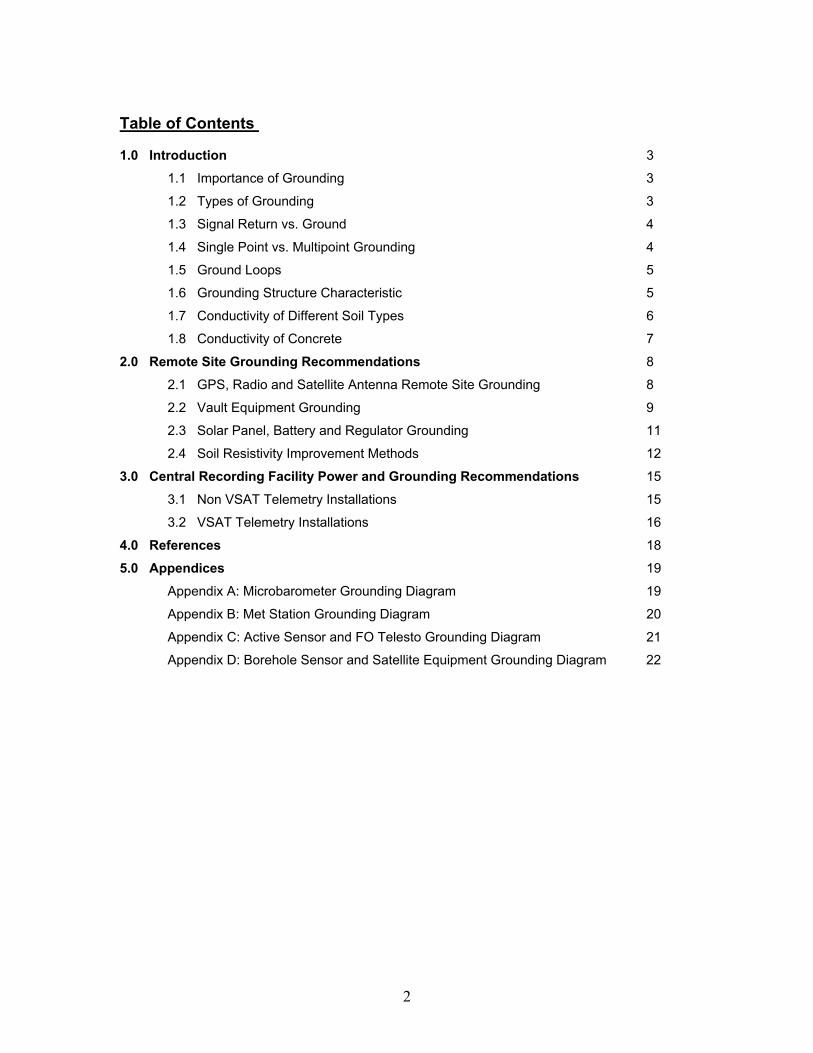
1.0 Introduction The objective of this document is to provide guidelines for the proper grounding of Nanometrics equipment. A brief introduction to some of the basic grounding concepts as well as some of the common misconceptions about grounding will be followed by grounding recommendations for Nanometrics installations. 1.1 Importance of Grounding Grounding is the primary way of minimizing unwanted noise in the system and ensuring the safe operation of equipment. A good grounding system is designed based on the common principles outlined in the following sections of this report. It is worth spending some extra time in sorting out the details of circuit and equipment grounding in order to avoid dealing with mysterious noise problems or safety issues once the cables have been designed and equipment installed. The advantage of a well designed ground system is that it does not add any cost to the product except for the engineering time needed to design it. An improperly designed ground system on the other hand may end up costing a lot more in damaged equipment repairs and engineering time needed to fix the noise problems. 1.2 Types of Grounding There are two main types of grounding: signal and safety grounding. Signal grounding requires the same voltage reference for different parts of the signal system. Proper signal grounding will minimize conductive, electromagnetic, magnetic (inductive) or electric (capacitive) noise coupling on the signals. The main purpose of safety grounding is to eliminate voltage differences between surfaces that may become energized and therefore present a shock hazard to the people operating the equipment [8]. Another purpose of safety grounding is to protect the equipment by providing a low impedance path to the ground in the case of large power surges due to the lightning strikes (earth grounding). It is important to mention the difference between the Safety and Earth Grounding. This difference is demonstrated in Figure 1.
groundfault
ground fault current path
low impedance pathto the ground
groundfault
high impedance pathto the ground
fuse or breakeropens
fuse or breaker does not open
a) Safety ground installed b) Only Earth ground installed
earth ground
earth ground
safety ground
Figure 1: Safety and Earth Grounding
In order to remove dangerous voltage due to a ground fault, an overcurrent protection device needs to open quickly. In order to open a fuse or a breaker quickly, the ground connection must have an impedance low enough to permit ground fault current to reach a level several times larger than the overcurrent protection devices rating. Safety ground connection as shown in
4
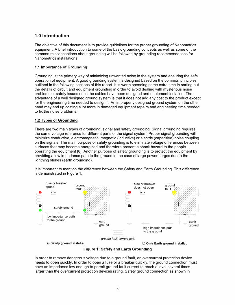
Figure 1a will provide that low impedance ground connection. Earth ground provides a connection to the ground of sufficiently low impedance to prevent the destruction of the equipment or electric shock which can occur due to superimposed voltages from lightning strikes. Earth connection however does not have low enough impedance to draw large currents needed to open the circuit breaker [8]. Safety grounding as described above is not required for metal parts of equipment that operates at 50V or less (which is the case for almost all of Nanometrics equipment installed at the remote sites). 1.3 Signal Return vs Ground Both signal and safety grounding conductors do NOT carry any current during the normal operating conditions. This is what distinguishes them from the signal and power return conductors [12]. Figure 2 demonstrates the difference as well as the different symbols used.
"hot"
"neutral""Gnd"
AC power
Internal Signal Circuit
SignalReturn
Signal Ground
Safety Ground
Figure 2: Difference between Return and Ground Wires
The signal return path carries signal current back to its source. The signal ground connection carries no current under normal operation. It provides a common voltage reference point for different circuits inside this enclosure (Europa for example). The neutral line provides a return path for the AC current. Safety ground line carries no current under normal operation. It provides a low impedance path to the ground in case the “hot” line got shorted to the Chassis [12]. This would cause large amounts of current to flow through the safety ground line causing the Ground Fault Circuit to trip as described in Section 1.2. 1.4 Single Point vs Multi Point Grounding It is important to distinguish when single point and when multipoint grounding needs to be used. Figure 2 is an example of where the single point grounding should be used. It is essential to have the Neutral and Gnd wires connected at only one point. That point is the Neutral Tie Block (see Figure 9). If this connection was made at more than one point then there would be a possibility of current flowing through the Gnd wire. As already mentioned in the previous section there must not be any current flowing through the grounding wires under normal operating conditions [12]. The same goes for the Signal Return connection to the Chassis of the instrument. The connection should be made at only one point to prevent any signal currents flowing through the Chassis. In general single point grounding is beneficial if the grounding structure is large in area and there are possibilities of potential differences between different parts of the grounding structure. If this is the case then there may be a current flowing through the grounding structure which may enter as noise through multiple grounding connections of the grounded instruments. Single point grounding would prevent this from happening. Multipoint grounding is usually used at the remote sites when connecting Nanometrics instruments to the earth ground. Multiple connections have the advantage of reducing the

5
potential differences between the grounded instruments and structures. In addition single point grounding must not be used if there is a distance of over 15m between the two pieces of the equipment. In this case there is going to be resistance in the wires due to the distance and a possibility a current flow in the grounding structure (which is what we are trying to avoid – see Section 1.6). In this case each instrument would have to be grounded individually using a multi point grounding scheme. 1.5 Ground Loops One of the greatest grounding misconceptions concerns ground loops. Ground loops, although a frequent cause of noise, are blamed for far more interference problems than they actually cause. Figure 2 demonstrates a difference between an actual ground loop setup and a setup that is often mistaken for a ground loop.
signal loop
ground loop
ground structure
Chassis # 1 Chassis # 2
signal loop
ground structure
Chassis # 1 Chassis # 2
1
not a ground loop
a) Real ground loop b) Mistaken for a ground loop Figure 3: Ground Loop Misconceptions
A ground loop is a conducting path that consists partially of the signal conductor and partially of the grounding structure as shown in Figure 3a. The ground loop has to have these two parts in order to bring noise into the system [6]. In the example above, the signal loop is grounded at both the source and the load ends. This is usually the case with single ended equipment. The duplicate ground path forms the equivalent of a loop antenna which very easily picks up interference currents. Lead resistances transform these currents into voltage fluctuations which get added to the signal as noise. The best way to eliminate this ground loop is to sever one of the Chassis connections at the point marked as #1 in Figure 3a. It is important not to remove any of the connections from the Chassis to Gnd since that would mean that one of the enclosures would be grounded through the signal return conductor (bad practice). Figure 3b shows a system setup which is often mistaken for a ground loop. In this case the loop consists of only the grounding wires which under normal operation carry no current. Since no part of this loop is a signal carrying conductor, there is not ground loop. 1.6 Grounding Structure Characteristics When choosing grounding structures there are several things to consider. The grounding structure obviously has to be an excellent conductor. It also has to have a “large” surface area compared to the system that is being grounded [12]. Finally the grounding structure has to be close to the system which is at a distance of no more than 15m. The actual distance depends on the type and size of the grounding wire. If the distance between the system and its grounding structure is larger than 10 - 15m, then due to the resistance in the grounding wire, there could be a potential difference between the equipment enclosures and the ground. This would defeat the
6
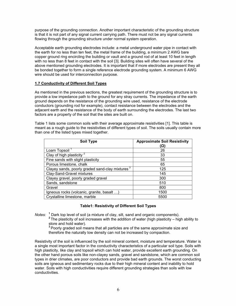
purpose of the grounding connection. Another important characteristic of the grounding structure is that it is not part of any signal current carrying path. There must not be any signal currents flowing through the grounding structure under normal system operation. Acceptable earth grounding electrodes include: a metal underground water pipe in contact with the earth for no less than ten feet, the metal frame of the building, a minimum 2 AWG bare copper ground ring encircling the building or vault and a ground rod of at least 10 feet in length with no less than 8 feet in contact with the soil [3]. Building sites will often have several of the above mentioned grounding electrodes. It is important that if more electrodes are present they all be bonded together to form a single reference electrode grounding system. A minimum 6 AWG wire should be used for interconnection purpose. 1.7 Conductivity of Different Soil Types As mentioned in the previous sections, the greatest requirement of the grounding structure is to provide a low impedance path to the ground for any stray currents. The impedance of the earth ground depends on the resistance of the grounding wire used, resistance of the electrode conductors (grounding rod for example), contact resistance between the electrodes and the adjacent earth and the resistance of the body of earth surrounding the electrodes. The last two factors are a property of the soil that the sites are built on. Table 1 lists some common soils with their average approximate resistivities [1]. This table is meant as a rough guide to the resistivities of different types of soil. The soils usually contain more than one of the listed types mixed together.
Soil Type Approximate Soil Resistivity (Ω)
Loam Topsoil 1 26 Clay of high plasticity 2 33 Fine sands with slight plasticity 55 Porous limestone, chalk 65 Clayey sands, poorly graded sand-clay mixtures 3 125 Clay-Sand-Gravel mixtures 145 Clayey gravel, poorly graded gravel 300 Sands, sandstone 510 Gravel 800 Igneous rocks (volcanic, granite, basalt …) 1500 Crystalline limestone, marble 5500
Table1: Resistivity of Different Soil Types
Notes: 1 Dark top level of soil (a mixture of clay, silt, sand and organic components).
2 The plasticity of soil increases with the addition of water (high plasticity – high ability to store and hold water). 3 Poorly graded soil means that all particles are of the same approximate size and therefore the naturally low density can not be increased by compaction.
Resistivity of the soil is influenced by the soil mineral content, moisture and temperature. Water is a single most important factor in the conductivity characteristics of a particular soil type. Soils with high plasticity, like clay and topsoil which can hold water, provide excellent earth grounding. On the other hand porous soils like non-clayey sands, gravel and sandstone, which are common soil types in drier climates, are poor conductors and provide bad earth grounds. The worst conducting soils are igneous and sedimentary rocks due to their high mineral content and inability to hold water. Soils with high conductivities require different grounding strategies than soils with low conductivities.

7
1.8 Conductivity of Concrete In some Libra installations satellite antennas are installed with penetrating mounts. These penetrating mounts are buried in concrete to a depth of 0.76m for a 1.2m antenna and up to1.2m for a 3.8m antenna. Concrete is a relatively poor conductor, with electrical characteristics that are quite similar to that of the dry sandy soil (see Sands in Table 1) [11]. The concrete, which surrounds the metal mount, makes up a non-homogeneous ground with the soil that surrounds it thus increasing the ground resistance. Therefore the satellite antenna should always be grounded to an external grounding structure.

8
2.0 Remote Site Grounding Recommendations The following three sections (2.1, 2.2 and 2.3) provide guidelines for grounding all of the Nanometrics equipment at the remote sites. It is important to note that the connections between Nanometrics equipment and the grounding structures are independent of the soil resistivity. The only thing that changes in the high resistivity soil is the resistance of the grounding structure itself. Section 2.4 describes several ways of bringing that resistance down. 2.1 GPS, Radio and Satellite Antenna Remote Site Grounding An antenna is usually the highest point at a particular site. Due to the height of the mast and the length of the RF cables (up to 40m on some sites), the mast and antenna structure and transmission cables can accumulate electrical charges placing them at a different potential from the equipment in the vault. This electrical charging combined with the height of the mast increases the probability of the structure being hit by lightning. It is to “draw off” this static electricity and to provide a low resistance path for high currents due to lightning strikes that the antenna structure must be properly grounded. Figure 4 shows a proper grounding technique for the mast which contains a GPS and a Yagi antenna.
Yagi Antenna
GPS Antenna
Grounding rod
1
2
R adio
Lightning Arres tor
3 connect to the electr ic al sy stem ground4
V aultto Satelli te antenna m as t ass embly
5
Figure 4: Antenna Structure Grounding Diagram
1. The antenna mast usually needs to be grounded using ground rods. If the conductivity of
the soil is high and the mast itself goes at least 8 feet underground then it can be used as a grounding electrode. If this is not the case then the mast needs to be grounded using

9
grounding rods as the ones described in section 1.6. In case of high soil conductivity, one rod may be enough. If the soil resistivity is high (see Section 1.7) then a system of interconnected grounding electrodes needs to be used in a circular pattern around the mast (see Section 2.4 for more details). A minimum # 6 AWG wire needs to be used to make the connection to the grounding electrode. It is important to get a good, solid connection (all paint needs to be removed) in order to minimize the resistance between the mast and the rod. It is also recommended to cover the connections with paint to prevent it from corroding.
2. All RF cables entering the vault need to be connected to the lightning arrestors. Lightning arrestors will direct any lightning strike currents to the ground. In order to do this effectively they have to be mounted (grounded) as close as possible to the entrance of the transmission lines into the vault [4]. The best way to ground them is to mount them to as straight and as large grounding surface area as possible. If no grounding plate is available in the vault then they can be connected to the grounding rod with a minimum # 10 AWG grounding wire.
3. If the remote site has several separate grounding electrodes (ex. one for the power system and one for the antenna structure) it is essential to bond all of the electrodes together using a minimum # 6 AWG grounding wire [8]. This way the vault will have a single grounding reference point and there would be no potential differences between different metallic surfaces. In Figure 4 a mast grounding rod is connected to the vault concrete wire mesh ground which is in turn connected to the electrical grounding system.
4. Finally if the grounding scheme is to be effective the grounding wire that is used to ground the system components and interconnect different grounding electrodes must be run as straight as possible. Sharp turns with the ground wire should be avoided since lightning charge has difficulty making such turns and therefore might discharge somewhere else [13]. There can also be no splices or connections in the ground wire between the equipment and grounding electrodes.
5. As mentioned in Section 1.8, a penetrating mount buried in concrete has often been used as a grounding structure. This is not good practice since the concrete has a very low conductivity compared to the high conductivity soils. Therefore it is important to ground the satellite antenna to an external (common) grounding structure using a minimum # 6 AWG grounding wire as shown in Figure 4. Another important aspect of grounding the satellite antennas is grounding the feedhorn assembly to the mast assembly. In 2.4m or larger antennas there is no physical conducting connection between the feedhorn assembly and the mast assembly. This connection should be made as described in Section 3.2 and Figure 10. In this way both surfaces of the antenna will be at the same potential and the risk of shock will be eliminated. The only time a penetrating mount should be used as a grounding structure is when there are no other grounding structures available at the site. Using the penetrating mount as a ground is a far better solution than using nothing.
2.2 Vault Equipment Grounding There are several main ways in which remote sites can be powered. The first way is by routing the DC power from the Central Site to each of the remotes. In this case high DC voltages are used and voltage drop in cables is taken into account. At the entrance into the vault there would be a junction box with a transformer in it which would output the necessary 12V. This box is shown as # 6 in Figure 5. The box would usually contain surge protectors as well. The second way remote sites are powered is through the solar panels and batteries at each site independently (see Section 2.4). The third way to power the remotes is by bringing the AC power to each remote site and then installing power supplies which would output the required12V DC. Bringing AC power is generally better because of the smaller voltage drop in the cables but one then must worry about the Safety Grounding of the power supply (as mentioned in Section 1.2).
10
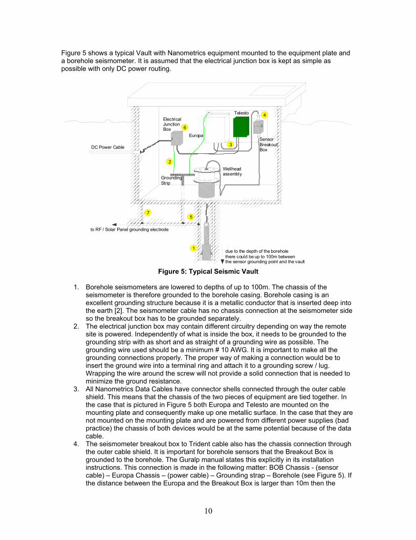
Figure 5 shows a typical Vault with Nanometrics equipment mounted to the equipment plate and a borehole seismometer. It is assumed that the electrical junction box is kept as simple as possible with only DC power routing.
DC Power Cable
1
2Wellheadassembly
Europa
Telesto
3
to RF / Solar Panel grounding electrode
4
57
6
due to the depth of the borehole there could be up to 100m between the sensor grounding point and the vault
Electrical Junction Box
Sensor BreakoutBox
GroundingStrip
Figure 5: Typical Seismic Vault
1. Borehole seismometers are lowered to depths of up to 100m. The chassis of the
seismometer is therefore grounded to the borehole casing. Borehole casing is an excellent grounding structure because it is a metallic conductor that is inserted deep into the earth [2]. The seismometer cable has no chassis connection at the seismometer side so the breakout box has to be grounded separately.
2. The electrical junction box may contain different circuitry depending on way the remote site is powered. Independently of what is inside the box, it needs to be grounded to the grounding strip with as short and as straight of a grounding wire as possible. The grounding wire used should be a minimum # 10 AWG. It is important to make all the grounding connections properly. The proper way of making a connection would be to insert the ground wire into a terminal ring and attach it to a grounding screw / lug. Wrapping the wire around the screw will not provide a solid connection that is needed to minimize the ground resistance.
3. All Nanometrics Data Cables have connector shells connected through the outer cable shield. This means that the chassis of the two pieces of equipment are tied together. In the case that is pictured in Figure 5 both Europa and Telesto are mounted on the mounting plate and consequently make up one metallic surface. In the case that they are not mounted on the mounting plate and are powered from different power supplies (bad practice) the chassis of both devices would be at the same potential because of the data cable.
4. The seismometer breakout box to Trident cable also has the chassis connection through the outer cable shield. It is important for borehole sensors that the Breakout Box is grounded to the borehole. The Guralp manual states this explicitly in its installation instructions. This connection is made in the following matter: BOB Chassis - (sensor cable) – Europa Chassis – (power cable) – Grounding strap – Borehole (see Figure 5). If the distance between the Europa and the Breakout Box is larger than 10m then the
11
Breakout Box needs to be grounded to the borehole separately. A # 10 AWG grounding wire should be used for this purpose.
5. As already mentioned the grounding strap, the borehole, the antenna mast lightning protection and all the other grounding structures have to be bonded together. This will provide a single grounding reference point and prevent voltage differences between different parts of the system [8]. These potential differences may show up in the form of the noise currents which are added to the signals.
6. Figure 6 shows DC power routing inside an electrical junction box. The chassis ground wire from the Europa and the Telesto power cables is connected to the grounded enclosure of the electrical junction box with a terminal ring. The chassis of these two devices are connected through the data cable as well. This does not constitute a ground loop as explained in Section 1.5. It is important to mention that the Europa is grounded through its power cable and so is the Janus. However if Janus and Trident are used instead of the Europa, it is important to know that the Trident is not grounded through the NMX Bus cable (this was done to avoid ground loops). This means that Trident needs to be grounded externally using a # 10 AWG wire and a screw attached to a threaded grounding hole on the side of the Trident frame.
from DC power source
Europa / Telestopower cables to the grounding
structure
Figure 6: Europa / Telesto Chassis Ground Connection
7. If the vault is made of metal then the metallic vault surface needs to be connected to the
grounding system. The same goes for the concrete vault with wire mesh in the concrete. It is a good practice to connect this wire mesh to the grounding structure [2].
2.3 Solar Panel, Battery and Regulator Grounding The solar panel frame and the solar regulator enclosure need to be grounded to the same earth grounding electrode as shown in Figure 7. In both cases a minimum # 10 AWG wire should be used with terminal rings connected to any of the screws on the solar panel frame. The solar regulator grounding wire should be left bare on the regulator side in order to connect to the grounding lug already supplied with the regulator. Europa, Cygnus, Janus or any other Nanometrics equipment that is powered through the regulator is also going to be grounded at the regulator through the power cables. The terminal strip, that loads power cables are supposed to be connected to, has three connection terminals. The first two are used for (+) and (-) connections, and the third one is used for grounding (it is connected to the regulator box chassis). An alternative way to ground the Nanometrics equipment would be to ground it externally through the chassis grounding point. This would mean attaching a grounding lug and a screw to the

12
grounding point (marked “Earth” on the Europa faceplate) as shown in Figure 7. This is a preferred method of grounding the Europa digitizer if power cables are long (10m or longer).
Solar Panel Frame
Solar Regulator
+
Battery
-
Everything groundedto the same groundingelectrode structure
Battery negative terminal grounded(assume negative ground version of the regulator)
Europa
Europa grounded through the grounding lugand NOT through the power cable (better connection)
Figure 7: Solar System Grounding Strategy The Negative terminal of the solar power system needs to be connected to the ground only if this connection has not been made anywhere else in the system. Nanometrics equipment such as the Europa, Trident, Janus, Cygnus and Carina do not have the connection between the power return and ground. However this connection exists inside the FF and FO Telestos (see Appendix C). If the above mentioned connection does not exist elsewhere then the negative or the positive terminal of the solar system should be connected to the ground as recommended by the solar regulator manufacturer. There are two types of solar regulators: a positive and a negative ground regulator. The manual supplied with the regulator indicates the type of the regulator but it is a good idea to double check (the manual has been wrong on at least one occasion). A negative ground version will have the Solar, Battery and Load negative terminals all connected together inside the regulator. A positive ground version will have common positive terminals. Therefore one can double check the version by buzzing out the positive and negative connections at the regulator. In case of the negative ground version, ground the negative terminal and in case of the positive ground version ground the positive terminal. In both cases the ground connection should be made at only one point (see Section 1.4). The best place to make that connection would be directly at the battery terminal as shown in Figure 7. 2.4 Grounding in High Resistivity Soils Table 1 is a good reference guide to the resistivity of different soil types. As already mentioned in the introduction to Section 2, all grounding methods described above apply to all Nanometrics Installations independent of the types of soil. The difference is that the grounding structures Nanometrics equipment is grounded to will have higher resistances in some areas due to the higher soil resistivities in those areas. This section will list some methods that can be used to lower the soil resistivity and therefore improve the resistance of the grounding structure at the site. Some of these methods require resources that may not be available at the site and are

13
therefore impractical. However in these cases Nanometrics engineers can make grounding recommendations which can be implemented at a later time. Methods of lowering the soil resistivity:
1. Use More Ground Rods It has been proven that two rods properly spaced and connected should have a combined resistance on the order of 60% of one rod (for 3 rods 40%) [9]. In general, proper spacing of the rods means placing them at least one rod length apart. They have to be interconnected using a minimum # 6 AWG wire and copper wire clamps. For maximum results (and if a large number of rods is available) they should be arranged in a radial configuration around the site as shown in Figure 8. The grounding rod specs have been given in Section 1.6.
Remote site equipment Vault
Multiple Grounding Rods
Heavy Wire Burial Longer Grounding Rods
Soil Treatment
Method 1
Method 2Method 3
Method 4
- high resistivity soil
- low resistivity soil
- ground enhancing material
wire trench
Figure 8: Methods of Lowering the Ground Resistivity
2. Increase Ground Rod Length Soil resistivity in many cases decreases with depth because there is an increase in moisture content. If this is the case then rods longer than the standard 10 feet may be required. A rather sharp decrease in the measured ground resistance will occur when a grounding rod reaches the low resistance soil [9]. This is why the borehole casings are the best possible grounds. This method would produce the best results if used with method 1. It is important to note that in very cold climates the grounding rod has to extend below the frost depth to have any effect. This is due to the fact that the temperatures below freezing increase soil resistivity (as soon as moisture turns to ice resistivity increases substantially). 3. Heavy Wire Burial If the site has only a thin layer of topsoil between the surface and the bedrock then the ground rod method would not be practical. The best grounding strategy in this case would be to bury a heavy # 4 AWG copper wire in a 12 – 18 inch deep trench around the site [9]. If the wire of this thickness is not available or is too expensive, lengths of copper pipe can be used instead. This ring would then need to be connected in several places to the central grounding element (antenna penetrating mount for example) with the wire of the same thickness. This

14
method can be further improved by driving a few short grounding rods (as deep as the topsoil) around the circle and then bonding them to the copper wire. 4. Soil Treatment This method is very effective but rarely practical due to the unavailability of the soil treatment materials. It involves treating the soil to lower its resistivity. One way to lower the resisitivity is to increase the moisture content of the soil (increasing the moisture content 5–10% lowers the resistivity significantly) [11]. This process would have to be repeated quite often since the problem with the soil in the first place is that it does not retain moisture. Unless the sites had easy accessibility and there was somebody to water the soil around the grounding rods repeatedly this method would not be effective. Another way to lower the resistivity is to treat the soil with salt (copper sulfate, magnesium sulfate or sodium chloride). Salts leach into the soil to reduce the resistivity [11]. This method is more durable and practical than the previous one since it involves considerably less maintenance work. The downside to the salt treatment is that it may corrode some of the grounding electrodes and it may be against local environmental regulations (ground water contamination). Finally the soil may be treated with ground enhancing materials like bentonite clay or coke powder [11]. These substances absorb the moisture from the surrounding soil and harden keeping the moisture within its structure. To apply such materials to the ground rod dig a hole around the ground rod about 6 inches in diameter. The depth of the hole should be a couple of inches shorter than the rod length. Apply the material to the hole (around the rod) and then bury the top portion of the hole with the soil as shown in Figure 8. If a wire method is used for grounding then fill the trench with about 1 inch of the material before placing the wire and then bury it together with the wire as shown in Figure 8. The biggest advantage of this method is that most of these materials are permanent and do not require any maintenance [11]. However their availability at the installation site is not likely. 5. Battery Negative Terminal Grounding If none of the above mentioned methods are feasible then the grounding structure should be connected to the battery negative terminal at only one point. Batteries usually have a very low internal resistance which makes them acceptable grounds in this case. This method would usually be used where no grounding electrodes are available at all. An example of this is the Antarctica system (can’t ground in ice). Another example are the systems installed in rocky environments with very little or no topsoil.

15
3.0 Central Recording Facility Power and Grounding Recommendations The following sections will list a few general pointers which if followed can minimize or eliminate possible power or grounding problems at Central Recording Facilities. 3.1 Non VSAT Telemetry Installations Figure 9 depicts a typical CRF room housing Nanometrics equipment. It can be seen that all of the grounding structures have been bonded together with # 6 AWG grounding wire. The grounding conductor used to bond different grounding structures must run as straight as possible. This reduces its length, and therefore resistance, and prevents arcing to any other non-grounding conductive media [4]. The arcing can occur if the grounding conductor makes sharp turns.
UPS
Ligh tni ngPro tectors
GPS A nte nna
Ligh tni ng protectiongro unding ro d
Ele ctrical system grou nding s tru cture
Ligh tni ng protec tion c ircuit conn ected to the elec trical system /equip me nt gro unding c ircuit w ith a m inim um 6 A WG w ire.
"h ot"
"n eutral"
Gnd
Yag i A nte nna
1
2
3
5
4
Equ ipm ent RackEqu ipm ent ra ck
C ircuit Bre ake r Neutral
T ie Block
6
FO Ca binet
FO C able
Figure 9: Typical Central Recording Facility
1. All Radio antennas and most of the GPS antennas have lightning arrestors in their
cables. These arrestors are only as good as the grounding system that they are connected to. For the best results arrestors should be connected to as straight and as large surface area as possible. This means mounting them directly onto a grounding plate if available in the room. If the grounding plate is not available then as short as possible minimum # 10 AWG grounding wire should be used to connect to a grounding rod or whatever other grounding structure is available. Finally the connection to the grounding structure should be made as close to the entrance of the transmission lines into the room as possible.
2. All equipment should be powered from the UPS. The UPS that is used should have a built in transient voltage surge suppressor (TVSS) circuitry to protect the equipment from voltage surges as well as short power outages.

16
3. Some previous instances have shown that customers preferred not to power the computer monitors through the UPSs. The reason for this has been that the computer monitors substantially increase the amount of power consumed, therefore shortening the amount of time the whole system can be powered by the UPS in case of a power outage. It is essential to power the monitor through the UPS (and power it down during outages). Any power surges or irregularities that may affect the computer monitor may affect the computer as well through the monitor connection to the graphic card (and therefore motherboard).
4. It is recommended to have air conditioners powered from an entirely different circuit than the Nanometrics equipment. Energizing the motors that are found in air conditioners can cause considerable voltage fluctuations which may damage AC-powered Nanometrics equipment [4].
5. The equipment rack is grounded through its AC power connection. However in some countries there is no separate ground wire in the AC power system. Rather than having the equipment rack grounded through the “neutral” of the AC power system, it is a good practice to ground the rack to the grounding plate with a # 10 AWG grounding wire.
6. Every fiber optic cable includes a central strength member. There are two types of central strength members: dielectric (coated glass, fiberglass rod) or metallic (coated steel). If a fiber optic cable has a steel central strength member then the cable may become a conductor of electricity in case of a nearby lightning strike (steel attracts lightning to the cable core). Since this same strength member is used to strain relieve FO cable at the entrance to the Cross Connect Cabinet it is necessary to ground the FO cabinet to prevent any potential build up. The grounding lug that is supplied with the cabinet should be used as well as a minimum10 AWG grounding wire. The connection to the grounding system should be as short and as straight as possible.
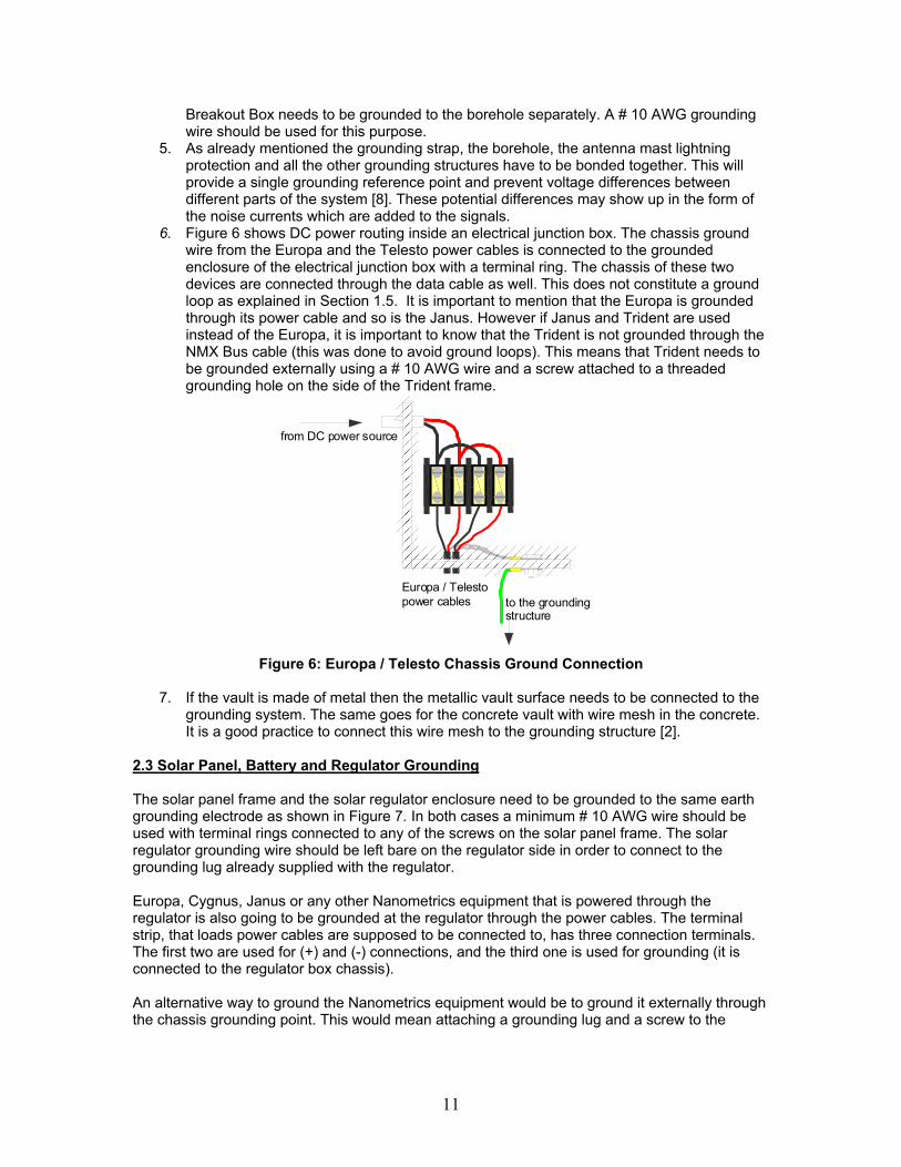
3.2 VSAT Telemetry Installations All of the non-VSAT CRF grounding pointers also apply to the CRF facilities housing VSAT equipment. VSAT installations however involve installation of a 3.8m (or bigger) antenna at the central site which requires some additional grounding considerations.
1
2
3.8m S ate llite Antenn a
to the gro unding s tr ucture
to C arina
C onne ct a m in 6 AW G ground w ire to o ne of the sc rew s on the fe edhor n
C onec t the other end of the feedhor n g round ing w ire to on e o f th e sc rew s on the ma st a se mb ly
Figure 10: 3.8m Antenna Ground Connections
17
Figure 10 shows a diagram of a 3.8m antenna that is usually installed at the central facility. Prodelin 3.8m antennas that Nanometrics uses have no physical conductive connection between the feedhorn and mast assemblies (new 3.8m antennas will have this connection). As a result of this there are 2 grounding recommendations that should be followed when a 3.8m antenna is installed.
1. The mast assembly needs to be grounded to the main building grounding system (like the one shown in Figure 9). If the antenna has been built on the rooftop using a pedestal mount then the antenna needs to be checked to confirm it has been grounded through the anchor rods. If this is not the case then a separate # 10 AWG (preferably a # 6 AWG) grounding wire should be used to connect the antenna to the buildings grounding system. In the case of the rooftop the closest grounding point would be the rooftop lightning protection ring. The same procedure would have to be followed if a non penetrating mount was used. If the 3.8m antenna has been installed on the ground beside the CRF and an in-ground mast used, a # 6 AWG grounding wire would need to connect the mast to the closest building grounding structure.
2. As previously mentioned there is no physical conducting connection between the feed and mast assemblies. Tx and Rx cables provide a safety ground connection for the feedhorn assembly as shown in Figure 11. This ground connection takes care of any potential build up on the feedhorn assembly. However this is not a good earth ground in case of any voltage surges due to lightning strikes. Another reason this is not a good earth ground is because of the distance between the feedhorn assembly and the grounding point of the Carina. The RF cables are usually 35m long and, as mentioned in Section 1.6, the grounding structure is too far to be an effective ground. Since the mast assembly has an earth ground connection as described in the previous paragraph, the feedhorn assembly needs to be connected to the mast assembly with a # 10 AWG grounding wire as shown in Figure 10.
Neutral Tie Block
Carina
LNB / SSPB NeutralGround
Ground
Neutral
Coax cable return connected to Carina and SSPB / LNB Chassis
Figure 11: Feedhorn Assembly Low Impedance Path to the Ground

18
4.0 References
1. ANSI/IEEE Std 142-1991, “Green Book,” IEEE Recommended Practice for Grounding of Industrial and Commercial Power Systems.
2. Bergman, Eric A. Manual of Seismological Observatory Practice. Global Seismological
Services, Golden, Colorado, USA, 2001.
3. Brownell, William B. The Grounding Electrode System. International Association of Electrical Inspectors (Grounding and Bonding Comitee), Rosemead, USA, 1999.
4. BuShea, Keneth R. Introduction to the Basics of Electrical Grounding for Power Systems.
Mining Electrical Maintenance & Safety Association Presentation, Clearwater, USA, 2002.
5. Donohoe, Patrick J. Grounding Equivalency of Steel Poles. Mississippi State University,
USA, 1999.
6. Engdahl Tomi, Ground Loop Basics. ELH Communications Ltd, USA, 2003.
7. Holt, Mike. Ground Rod Does Not Reduce Touch Potential. Mike Holt Enterprises, Inc., Tamarac, Florida, USA, 2003.
8. Holt, Mike. Guide to Low Voltage & Limited Energy Systems. Mike Holt Enterprises, Inc.,
Tamarac, Florida, USA, 1999.
9. Nielsen, R.W. Reducing Resistivity In An Electrical Grounding System. Permanent Buildings and Foundations, Utah, USA, 1995.
10. Ott, Henry W. Noise Reduction Techniques in Electronic Systems – Second Edition. John
Wiley and Sons, Inc., New York, USA, 1998.
11. Switzer, Keith. Achieving an Acceptable Ground in Poor Soil. PRIMEDIA Business Magazines & Media Inc., USA, 2003.
12. Van Doren, Tom. Grounding and Shielding Electronic Systems. Course Workbook, USA,
1999.
13. Wiles, John. Grounding the South Forty. Southwest Technology Development Institute, New Mexico State University, Las Cruces, USA, 2000.
19
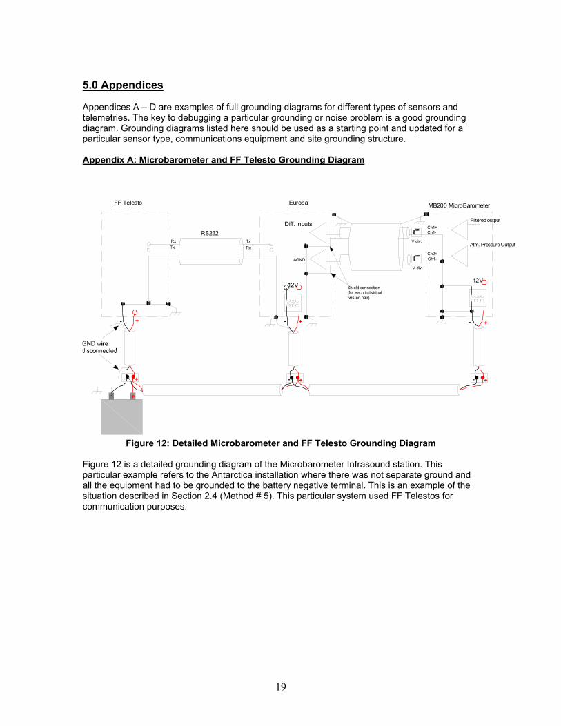
5.0 Appendices Appendices A – D are examples of full grounding diagrams for different types of sensors and telemetries. The key to debugging a particular grounding or noise problem is a good grounding diagram. Grounding diagrams listed here should be used as a starting point and updated for a particular sensor type, communications equipment and site grounding structure. Appendix A: Microbarometer and FF Telesto Grounding Diagram
12V
Filtered output
Atm. Pressure Output
MB200 MicroBarometer
-
+
Ch1+Ch1-
12V
-
+
Ch2+Ch1-
Europa
-
+ -
+
Diff. inputs
-
+
-
+
RS232TxRxTx
Rx
FF Telesto
+-
AGND
Shield connection(for each individual twisted pair)
V div.
V div.
Figure 12: Detailed Microbarometer and FF Telesto Grounding Diagram Figure 12 is a detailed grounding diagram of the Microbarometer Infrasound station. This particular example refers to the Antarctica installation where there was not separate ground and all the equipment had to be grounded to the battery negative terminal. This is an example of the situation described in Section 2.4 (Method # 5). This particular system used FF Telestos for communication purposes.

20
Appendix B: Met Station Grounding Diagram
-
+
12V
-
+
-
+ -
+
+-
12V+-
Sig nal Re fere nce
Temperature
Rel. Humidity
+-
Atm. Pressure
Sig nal Re fere nce
+-
Wind Vel.
Wind Dir.
AGND
12V
12V
-
+
-
+24V Power Supply
Battery12V Power Supply
- 24V
Vol t. Divider
Vol t. Divider
CH1+CH1-
CH2+CH2-
MP3
MP2
CH3+CH3-
AGND
AGND
Wind Vel.
Wind Dir.
Temperature
AGND
AGND
AGND
AGND
Rel. Humidity
Atm. Pressure
EUROPA MET BREAKOUT BOX Gill WindObserver II Wind Sensor
Temperature and Rel. Humidity Sensor
Barometric Pressure Sensor
Figure 13: Detailed Met Station Grounding Diagram
Figure 13 shows the grounding diagram of the Met Station for the same Antarctica system as in Appendix A. It shows the grounding connections inside the Met Station sensors (all of which are single ended) and Met Breakout Box. As already mentioned due to the lack of any ground all of the equipment had to be grounded to the battery negative.

21
Appendix C: Active Sensor and FO Telesto Grounding Diagram
12V
-
+
CH1+CH1-
CH2+CH2-AGND
AGND
AGND
EUROPA / TRIDENT
CH3+CH3-
+-
CAL+
CAL -
DGND
GNDRET
+12V
ACTIVE SENSOR (TRILLIUM in this example)
Cal Coil
Active sensor chassis grounded through the digitizer
-
+
RS232TxRxTx
Rx
FO Telesto
power return grounded to the chassis
vault grounding structure
Active sensor chassis grounded through the digitizer
Figure 14: Active Sensor (Trillium) System Grounding Diagram
Figure 14 shows a typical active seismometer connection to the Nanometrics digitizer. Note that the chassis of the sensor is grounded through the digitizer chassis. Note as well that there is a connection between the analogue and digital grounds inside the digitizer. This is to make sure that both circuits have a common signal reference as mentioned in Section 1.2. Both of these circuits are referenced to the digitizer chassis. Finally note that inside the FO Telesto there is a connection between the power return and ground. As already mentioned in Section 2.3 if this site was powered by the solar system there would be no need to ground the battery negative terminal because this has already been done inside the FO Telesto (the same applies to FF Telesto).
22
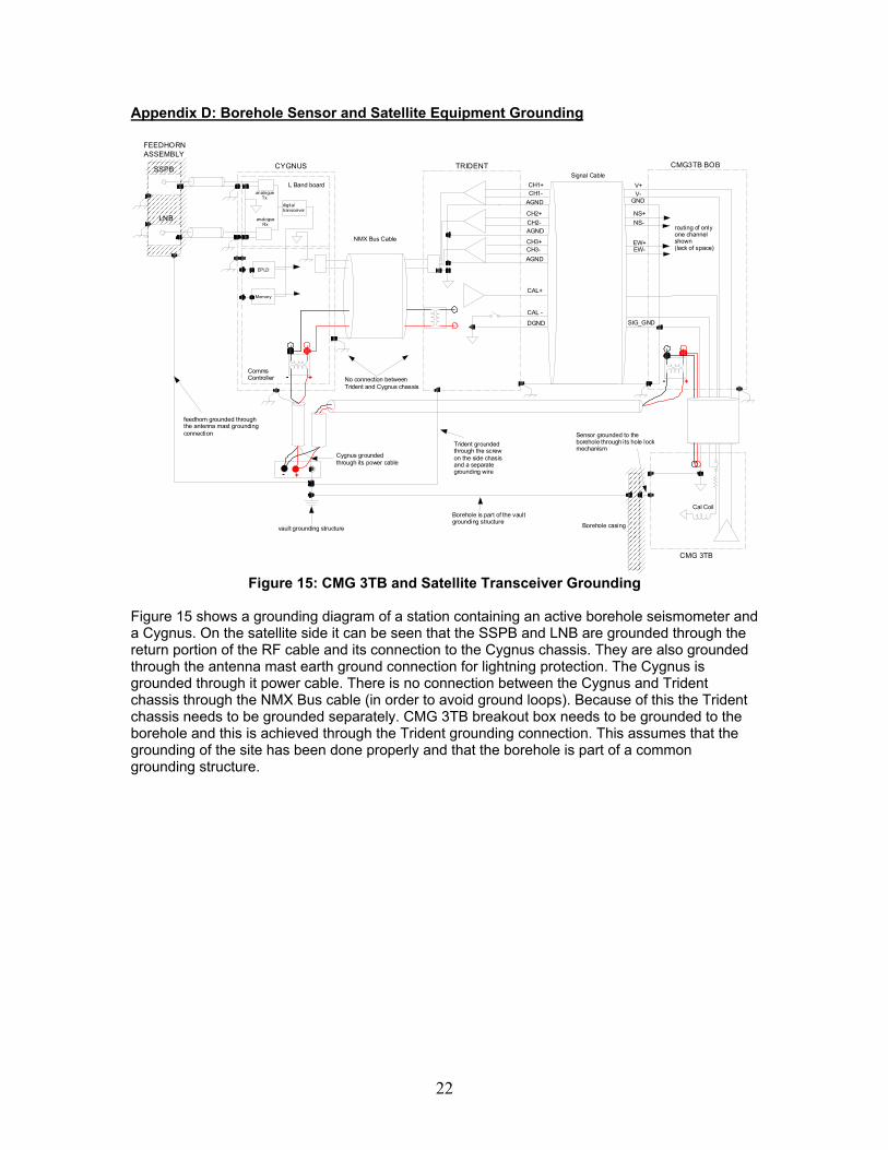
Appendix D: Borehole Sensor and Satellite Equipment Grounding
CH1+CH1-
CH2+CH2-AGND
AGND
AGND
TRIDENT
CH3+CH3-
CAL+
CAL -
DGND
Signal Cable
NMX Bus Cable
-
+
CYGNUS
L Band board
CommsController
SSPB
LNB
FEEDHORNASSEMBLY
digitaltransceiver
analogue Tx
analogue Rx
EPLD
Memory
+-
vault grounding structure
feedhorn grounded through the antenna mast groundingconnection
No connection betweenTrident and Cygnus chassis
Cygnus grounded through its power cable
V+V-
GND
NS+NS-
EW+EW-
SIG_GND
CMG3TB BOB
Trident groundedthrough the screw on the side chasis and a separategrounding wire
+
routing of only one channel shown (lack of space)
-
CMG 3TB
Sensor grounded to theborehole through its hole lock mechanism
Borehole is part of the vaultgrounding structure
Cal Coil
Borehole casing
Figure 15: CMG 3TB and Satellite Transceiver Grounding
Figure 15 shows a grounding diagram of a station containing an active borehole seismometer and a Cygnus. On the satellite side it can be seen that the SSPB and LNB are grounded through the return portion of the RF cable and its connection to the Cygnus chassis. They are also grounded through the antenna mast earth ground connection for lightning protection. The Cygnus is grounded through it power cable. There is no connection between the Cygnus and Trident chassis through the NMX Bus cable (in order to avoid ground loops). Because of this the Trident chassis needs to be grounded separately. CMG 3TB breakout box needs to be grounded to the borehole and this is achieved through the Trident grounding connection. This assumes that the grounding of the site has been done properly and that the borehole is part of a common grounding structure.