OVERUSE INJURIES IN THE ERA OF SPORT SPECIALIZATION Lauren Shull, MD-R PGY-3.

NANOMAGNETISM (I)
WHAT IS IT????
SO WHAT????
Robert D. Shull
Leader: Magnetic Materials Group,
National Institute of Standards and Technology
V. President: The Minerals, Metals, & Materials Society (TMS)
Member: OSTP Nanoscale Science, Engineering
and Technology Subcommittee, NSET
Magnetic Materials Group
OUTLINE
(I).
(II).
(III).
(IV).
What is Nanotechnology??
Why is it Different???
Nanomagnetism Changes
Summary
-New Magnetic States
-Time Dependence
-Soft Magnetic Behavior
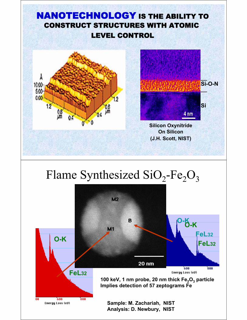
O-K
FeL32O-K
FeL32
Sample: M. Zachariah, NIST
Analysis: D. Newbury, NIST
100 keV, 1 nm probe, 20 nm thick Fe2O3 particle
Implies detection of 57 zeptograms Fe
Flame Synthesized SiO2-Fe2O3
O-K
FeL32

QUANTUM CORRALS (Fe on Cu)
(Don Eigler, IBM Almaden)

AFM Tip
Writing direction
Water meniscus
Molecular transport
Substrate
Dip Pen Lithography: Chad Mirkin (Northwestern Univ.)
Plasma or Vapor DepositionMechanical Alloying
PRODUCTION METHODS
NIL – S. Chou (Princeton)
PRODUCTION METHODS
Inert Gas Condensation (IGC)
Plasma Vapor Deposition (PVD)
Condensed Vapor Deposition (CVD)
Pulsed Laser Deposition (PLD)
Chemical Precipitation from Solution
Solid Solution Precipitation
Mechanical Alloying (MA)
Ion Replacement & Reduction
Sputtering
Electrodeposition
Filling of Nanopores
Dip Pen Lithography
Nanoimprint Lithography (NIL)
Self Assembled Monolayers (SAMs)
Atomic Force Microscope
Rapid Solidification (RSP)
Sol Gel Chemistry
.
..
AFM – D. Eigler (IBM)
QUANTUM CORRAL (Fe atoms on Cu)

THREE REASONS
WHY PROPERTIES ARE DIFFERENT
WHEN MATERIALS POSSESS
SOME NANOSCALE DIMENSION
(1)

(2)

Resistivity – mean free path
Thermal Conductivity – mean free path
Strength – dislocation Burgers vector
Transmission & Reflection - wavelength
Diffraction & Scattering - wavelength
Absorption – penetration depth
Atomic Transport – diffusion length
Superconductivity – coherence length
Elasticity – bond & chain lengths
Reaction Rate – diffusion length
Boundary Motion – radius of curvature
Fluid Flow – boundary layer thickness
Magnetism – exchange length, domain wall width
CRITICAL LENGTH SCALES(3)
(Calculated by Michael Coey, Univ. of Dublin)

Spherical Particle Disc-Shaped Particle Rod-Shaped Particle
Fiber Intergranular Film Layered
NANOCOMPOSITE MORPHOLOGIES
Critical Dimensions:
Particle Diameter, Separation Distance, Aspect Ratio,
Fiber Diameter, Layer Thickness, Grain Diameter, …

= Superparamagnetic Material:
SMALL PARTICLE BEHAVIOR
Assembly of magnetic clusters (each comprised of many
ferromagnetically-aligned elemental moments of magnitude )
acting independently.
Magnetic Materials Group
Magnetic Materials Group
+H-H
-M
+M
Coercivity
Saturation MSRemanent MR
Coercivity
Remanent MR
HYSTERESIS LOOP OF A FERROMAGNET

Magnetic Materials Group
-9 -7 -5 -3 -1 1 3 5 7 9
60
40
20
0
-20
-40
-60
300 K
Applied Field (102 kA/m)
Ma
gn
eti
za
tio
n (
Am
2/k
g)
Applications:
Magnetic InksMagnetic Separation
Vacuum SealingMagnetic Marking
Magnetic RefrigerationMagnetic Resonance Imaging
No Remaining Magnetism Upon Field Removal!!!
(Occurs when Particles are Very Small and Decoupled)
SUPERPARAMAGNETISM
Magnetic Materials Group
A New
Concern
for Nano-
Magnetic
Materials
For conventional
Ferromagnets,
there is no time
dependence, so
this is a new
constraint on the
application of
Nanomagnets.

Magnetic Materials Group
Two-Step Field-
Change Method
Results in
2 Time Constants!
TIME DEPENDENCE
Which Method
is Best???

Magnetic Materials Group
Kinetically Frozen Nanoparticle Moments
In nanoparticles, the
Magnetic moments
can be kinetically frozen
if the temperature is
low enough. That
temperature is called
the “blocking”
temperature: TB . That
temperature depends
slightly upon how it is
measured. It also
depends on the Volume
of the material and the
magnetic anisotropy
of that material.
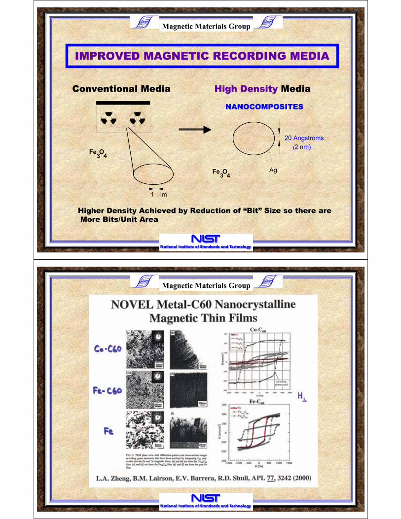
HIGHER DENSITY
MAGNETIC RECORDING MEDIA
CHANGES WITH SIZE REDUCTION
(BOTH THICKNESS & LATERAL SIZE)
Magnetic Materials Group
Fe3 4O
1 m
20 Angstroms
Ag
(2 nm)
Fe3 4O
NANOCOMPOSITES
Conventional Media High Density Media
IMPROVED MAGNETIC RECORDING MEDIA
Higher Density Achieved by Reduction of “Bit” Size so there are
More Bits/Unit Area
Magnetic Materials Group

Magnetic Materials Group
-9 -7 -5 -3 -1 1 3 5 7 9
60
40
20
0
-20
-40
-60
300 K
Applied Field (102 kA/m)
Ma
gn
eti
za
tio
n (
Am
2/k
g)
Applications:
Magnetic InksMagnetic Separation
Vacuum SealingMagnetic Marking
Magnetic RefrigerationMagnetic Resonance Imaging
No Remaining Magnetism Upon Field Removal!!!
(Occurs when Particles are Very Small and Decoupled)
SUPERPARAMAGNETISM SETS A LIMIT
TO PARTICLE (“BIT”) SIZE REDUCTION!!!

Magnetic Materials Group
MAGNETORESISTANCE
Recorder Heads
MagnetoresistiveRead Head
(e.g., permalloy)
Giant Magnetoresistance
(GMR) Heads
NEED FOR
HIGHER
SENSITIVITY
MAGNETIC
FIELD
SENSORS
WITH
PARTICLE
SIZE
REDUCTION
(Also true for Biological
Applications of Small
Magnetic Particles)
= 2.5% )( /
> 50% )( /

[Baibich, et. al., Phys. Rev. Lett. 61, 2472 (1988).]
Magnetic Materials Group
Saturation Field or Coercivity (Oe)
GM
R (
%)
TYPICAL PUBLISHED RESULTS
101 102 103 104 105100
10
20
30
40
50
60
70
80
90
100
110
0

SOFT MAGNETIC
PROPERTIES ARE DIFFERENT
WHEN MATERIALS POSSESS
SOME NANOSCALE DIMENSION
TRANSFORMER
“Hysteresis Loop” of Ferromagnet
i2
i1
115 v AC 20 v AC
+
-
+
-
Ferromagnet
Magnetization
Magnetic Field
Area = Energy Loss-
-
+
+
Coercivity

Magnetic Materials Group
+H-H
-M
+M
Magnetization Reversal byDomain Nucleation & Growth
(Most Common Mechanism)
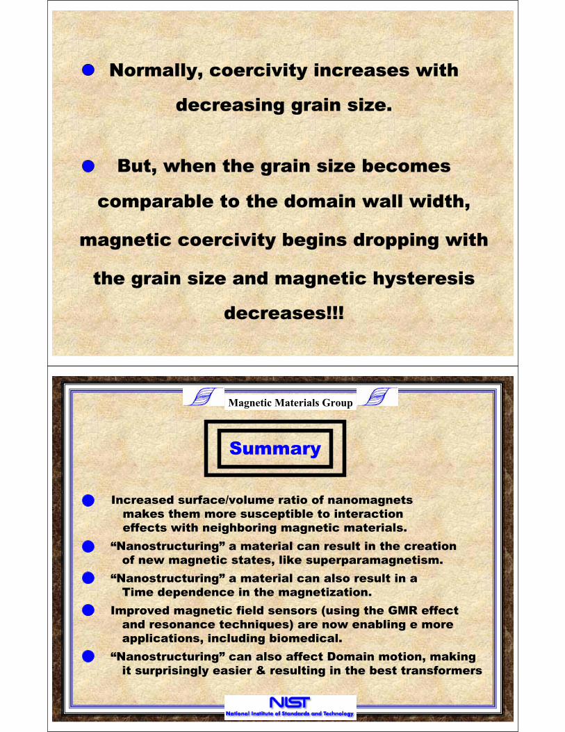
But, when the grain size becomes
comparable to the domain wall width,
magnetic coercivity begins dropping with
the grain size and magnetic hysteresis
decreasing grain size.
Normally, coercivity increases with
decreases!!!
Magnetic Materials Group
Summary
Increased surface/volume ratio of nanomagnets
makes them more susceptible to interaction
effects with neighboring magnetic materials.
“Nanostructuring” a material can result in the creation
of new magnetic states, like superparamagnetism.
“Nanostructuring” a material can also result in a
Time dependence in the magnetization.
Improved magnetic field sensors (using the GMR effect
and resonance techniques) are now enabling e more
applications, including biomedical.
“Nanostructuring” can also affect Domain motion, making
it surprisingly easier & resulting in the best transformers

NANOMAGNETISM (II)
DOMAINS
IN NANO-FERROMAGNETS???
Robert D. Shull
Leader: Magnetic Materials Group,
National Institute of Standards and Technology
V. President: The Minerals, Metals, & Materials Society (TMS)
Member: OSTP Nanoscale Science, Engineering
and Technology Subcommittee, NSET
Magnetic Materials Group
OUTLINE
(I).
(II).
(III).
(IV).
Domains in Nanomaterials?
Size Dependence
Domains in Thin Film Nanocomposites
Summary
-AF/FM Bilayers
-AF/FM Bilayers (AC-Demagnetized)
-Hard/Soft FM Bilayers

Magnetic Materials Group
+H-H
-M
+M
Magnetization Reversal byDomain Nucleation & Growth
(Most Common Mechanism)
Magnetic Materials Group
DO DOMAINS
EXITS IN
NANOCRYSTALLINE
FERROMAGNETS???
Domains require an
anisotropy to exist. Since
the magnetocrystalline
anisotropy is thought to
go to zero in nanocrystalline
materials, do magnetic
domains actually exist in
these materials???

Magnetic Materials Group
H
(A) (B)
(C) (D)
H=0 H>HA
H>HB H>HC
Domain Patterns in Nanocrystalline (d=18 nm) Ni
(Imaged by Magnetic Fluid Method)
Field dependent
patterns in a
magnetic fluid on
top of Nano-Ni
shows domains
exist and grow
with the field.
The patterns also
show the domains
are much larger
than the grains at
H=0.
DOMAIN WALLS
ARE ALSO A FUNCTION OF
SIZE

Magnetic Materials Group
Computational Standards
Magnetic Materials Group
R.D. McMichael & M.J. Donahue, IEEE Trans. Magnetics 33, 4167 (1997).
Walls Separating
Magnetic Domains
Change as the Domain
Dimensions Change
This Changes the Way
Domains Grow in
Response to a Magnetic
Field Application.
This Affects the Shape,
Width, and Area Enclosed
In the Hysteresis Loop of
that Material.

Magnetic Materials Group
In a Ferromagnet,
domains are a way
to reduce the
magnetostatic
energy of the
material.
Sooner or later, it
costs too much
energy to Create
a wall.
Particles less than
this minimum size
are a single
magnetic domain.
CHANGE IN DOMAIN DYNAMICS
IN NANOCOMPOSITE SYSTEMS
EXAMPLE:
- IN A SPIN VALVE READ HEAD


Magnetic Materials Group
Exchange Bias Hysteresis Loops
+H-H
-M
+M
Coercivity
Saturation MSRemanent MR
Coercivity
Remanent MR
0
Magnetic Materials Group
Magnetic Materials Group
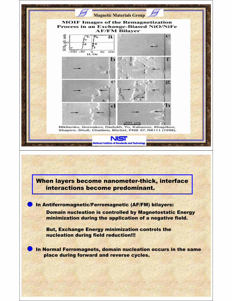
Domain nucleation is controlled by Magnetostatic Energy
minimization during the application of a negative field.
But, Exchange Energy minimization controls the
nucleation during field reduction!!!
In Antiferromagnetic/Ferromagnetic (AF/FM) bilayers:
In Normal Ferromagnets, domain nucleation occurs in the same
place during forward and reverse cycles.
When layers become nanometer-thick, interface
interactions become predominant.
Magnetic Materials Group
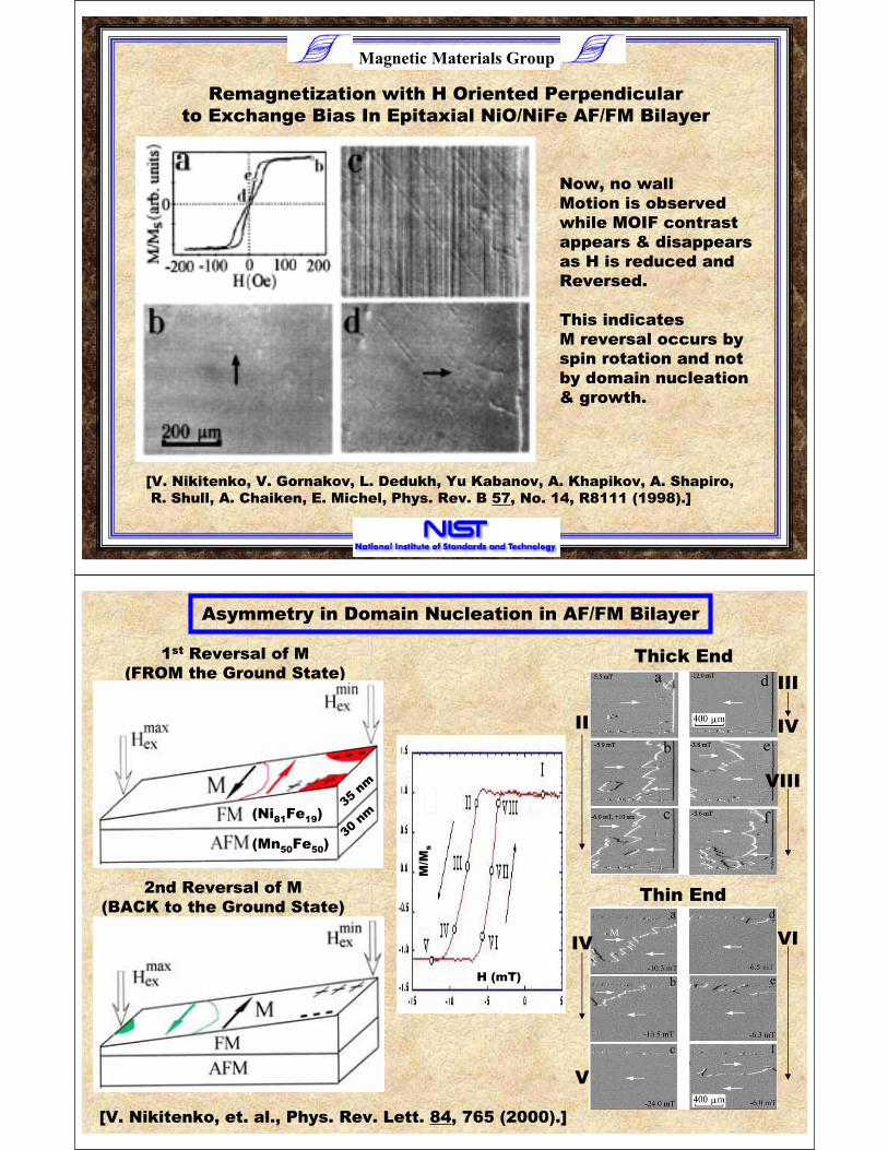
Remagnetization with H Oriented Perpendicular
to Exchange Bias In Epitaxial NiO/NiFe AF/FM Bilayer
Now, no wall
Motion is observed
while MOIF contrast
appears & disappears
as H is reduced and
Reversed.
This indicates
M reversal occurs by
spin rotation and not
by domain nucleation
& growth.
[V. Nikitenko, V. Gornakov, L. Dedukh, Yu Kabanov, A. Khapikov, A. Shapiro,
R. Shull, A. Chaiken, E. Michel, Phys. Rev. B 57, No. 14, R8111 (1998).]
H (mT)
M/M
s
Thin End
VIIV
V
Thick End
II
III
IV
VIII
1st Reversal of M
(FROM the Ground State)
2nd Reversal of M
(BACK to the Ground State)
[V. Nikitenko, et. al., Phys. Rev. Lett. 84, 765 (2000).]
Asymmetry in Domain Nucleation in AF/FM Bilayer
(Ni81Fe19)
(Mn50Fe50)
35nm
30nm

Magnetic Materials Group
1stR
eve
rsa
l o
f M
(FR
OM
th
e G
rou
nd
Sta
te)
2nd R
evers
al of
M
(BA
CK
to
th
e G
rou
nd
Sta
te)
Asymmetry in Domain Dynamics in AF/FM Bilayer
Note the Vertical
Defect does NOT
affect the domain
motion during the
1st Reversal, but
DOES affect the
Motion during the
2nd reversal.
[V. Nikitenko, V. Gornakov, A. Shapiro, R. Shull, K. Liu, S. Zhou, C. Chien,
Phys. Rev. Lett. 84, 765 (2000).]
H
Magnetic Materials Group
Domain Dynamics in FeMn/NiFe AF/FM Bilayer
(AC Demagnetized at T>TNeel of AF)
Field Cooled (Exchange Biased) AC-Demagnetized
C. Chien, V. Gornakov, V. Nikitenko, A. Shapiro, R. Shull,
IEEE Trans. Magnetics 38, No. 5, 2736 (20002).]

Magnetic Materials Group
(I) (II)
(III)(IV)
(I) (II)
(III)(IV)
Residual Image at top and bottom
of original domain structure show
original AF domains have not moved
While the FM domains changed.
Domain Motion in AC Demagnetized FeMn/NiFe AF/FM Bilayer
[Chien, Gornakov, Nikitenko, Shapiro, Shull, IEEE Trans. Magnetics 38, No. 5, 2736 (20002).]
Magnetic Materials Group
Domain motion in
AC-Demagnetized AF/FM
Bilayer can be explained
By the formation of an
Exchange spring parallel
To the AF/FM interface,
Pinned at one end by the
AF and at the other end by
the FM
CHANGE IN DOMAIN DYNAMICS
IN NANOCOMPOSITE SYSTEMS
EXAMPLE:
- IN AN IMPROVED PERMANENT MAGNET
Magnetic Materials Group
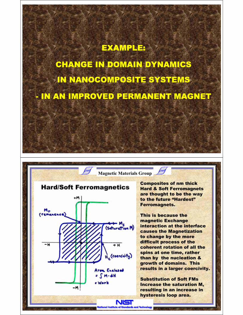
Composites of nm thick
Hard & Soft Ferromagnets
are thought to be the way
to the future “Hardest”
Ferromagnets.
This is because the
magnetic Exchange
interaction at the interface
causes the Magnetization
to change by the more
difficult process of the
coherent rotation of all the
spins at one time, rather
than by the nucleation &
growth of domains. This
results in a larger coercivity.
Substitution of Soft FMs
Increase the saturation M,
resulting in an increase in
hysteresis loop area.

Magnetic Materials Group
The make the “Hardest”
Ferromagnetic materials
(i.e., for the strongest
permanent magnets),
advantage is taken of the
Interface effects.
The best Nd-Fe-B magnets
are intentionally made
off-stoichiometry in order
to make them multiple
phase so there are many
interfaces.
The “Hard” phase is also
made nanometer in size
in order to increase the
interface area.
Magnetic Materials Group
Origin of High Coercivity in Hard/Soft
Ferromagnetic Bilayer
Bottom Layer of the Soft
Ferromagnet (Fe) is pinned
by the top layer of the
Hard Ferromagnet (SmCo).
Each successive layer in
the Soft FM is bound to the
layer below it causing
its magnetic moment to be
closely aligned to it. The
further away each Soft FM
layer is from the AF
interface, the easier it is to
align with the external
field, thereby creating a
“spin spiral”. This keeps
domain walls perpendicular
to the interface from forming.[E. Kneller & R. Hawig,
IEEE Trans. Mag. 27, 3588 (1991).]

Magnetic Materials Group
Since No MOIF image
contrast was observed
on the top of the soft FM
(Fe) in a SmCo/Fe Bilayer
During field reversal, a
Trick was employed. A
small hole was drilled
through the bilayer, and
the magnetization in the
area was determined by
the magnetic poles of
opposite sign which
formed on the opposite
inside edges of the hole.
Domain Imaging
Of a SmCo/Fe
Hard/Soft FM
Bilayer
Magnetic Materials Group
Proof of Rotation Reversal Process in SmCo/Fe Bilayer
Application of a
reversed field is shown
by the rotation of the
MOIF image contrast
at the hole edges to be
accompanied by a
rotation of M, when H
is aligned just slightly
off the easy axis of
Magnetization of the
Fe.
MOIF images with no
hole present showed
no contrast, indicating
no domain walls
perpendicular to the
surface as would be
expected for a normal
FM.

Magnetic Materials Group
New Feature in the Reversal Process in SmCo/Fe Bilayer
When H is aligned
along the easy axis
of magnetization of
the Fe, reversal of H
does not result in a
rotation in the
contrast at the hole
edge, but it is
accompanied by an
overall reduction in
image contrast.
This effect is caused
by a distribution in
directions of the easy
axes of magnetization
in the small grains of
the material: some
rotating clockwise
& some rotating CCW
in response to H.
Magnetic Materials Group
[J. Jiang, E. Fullerton, C. Sowers, I. Inomata, S. Bader, A. Shapiro, R. Shull,
V. Gornakov, V. Nikitenko, IEEE Trans. Magnetics 35, 3229 (1999).]
Improved
Permanent
Magnet By
Multilayers
of nm-thick
SmCo & Fe
Best Nd-Fe-B
Permanent
Magnet
Hysteresis Loop
Area

Magnetic Materials Group
Summary
Increased surface/volume ratio of nanomagnets makes
domain motion more susceptible to interaction
effects with neighboring magnetic materials.
The usefulness of a material for a particular application
depends on how easily or hard it is to change its
magnetization.
AF/FM Exchange Biased films possess a novel asymmetry
in their reversal behavior
Nanocomposites provide a means for designing better
Hard ferromagnets (i.e., permanent magnets)
Observation of Domain patterns is critical to understanding
how a material changes its magnetization.
Magnetic Materials Group
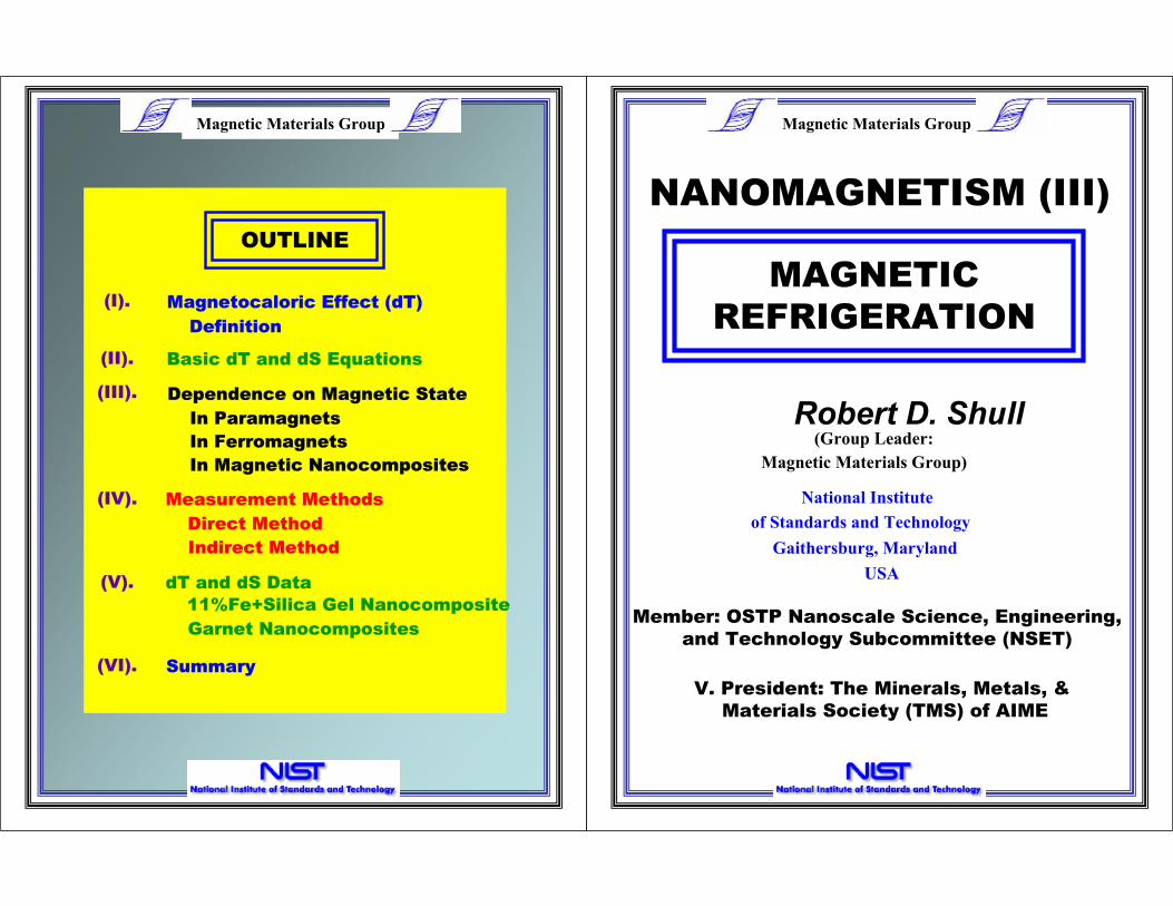
Robert D. Shull(Group Leader:
Magnetic Materials Group)
National Institute
of Standards and Technology
Gaithersburg, Maryland
USA
MAGNETIC
REFRIGERATION
NANOMAGNETISM (III)
V. President: The Minerals, Metals, &
Materials Society (TMS) of AIME
Member: OSTP Nanoscale Science, Engineering,
and Technology Subcommittee (NSET)
Magnetic Materials Group
Dependence on Magnetic State
In Paramagnets
In Ferromagnets
In Magnetic Nanocomposites
Definition
Basic dT and dS Equations
Measurement Methods
Direct Method
Indirect Method
Magnetocaloric Effect (dT)
(III).
dT and dS Data
Summary(VI).
(I).
(II).
(IV).
(V).
OUTLINE
Garnet Nanocomposites
11%Fe+Silica Gel Nanocomposite

Magnetic Materials Group
MAGNETOCALORIC EFFECT
SYSTEM = SPIN + LATTICE
at H = 0 T = T0
at H = HApplT = T1
spins lattice
Total entropy change of the (Spin +
Lattice) system upon application of a
magnetic field, HAppl, (reversibly) is
ZERO.
Decrease in spin entropy causes an
increase in lattice entropy, CHdT/T.
Magnetocaloric effect = dT = (T1-T0).
Magnetic Materials Group
I
II
III
IV
T2
T3
T1
T4
Tem
pe
ratu
re
Entropy
H=0
a
b
c
d H=HoFiel
d
Steps , : AdiabaticI III
i
Magnet
Windings
Heat Exchanger: A
Heat Exchanger: B
Tube filled with
heat exchange fluid
Nanocomposite
Refrigerant
Magnetic
Cyclic motion of the
refrigerant in and out of
the field
(Heat)
(Heat)
T1
T3
Shutter
MAGNETIC REFRIGERATION
Refrigeration Cycle
Refrigerator

Magnetic Materials Group
WHY
MAGNETIC
REFRIGERATORS
?????
Large Entropy Change in Ordering
Based on a REVERSIBLE Process
Refrigerant and Heat Transfer Media
(40-200 times that of a gas)
(Carnot efficiencies conceivable)
are DIFFERENT
(No chlorofluorocarbons)
No Compressor & Few Moving Parts
(Low vibration, High durability)
Magnetic Materials Group
Magnetic Materials GroupMagnetic Materials Group
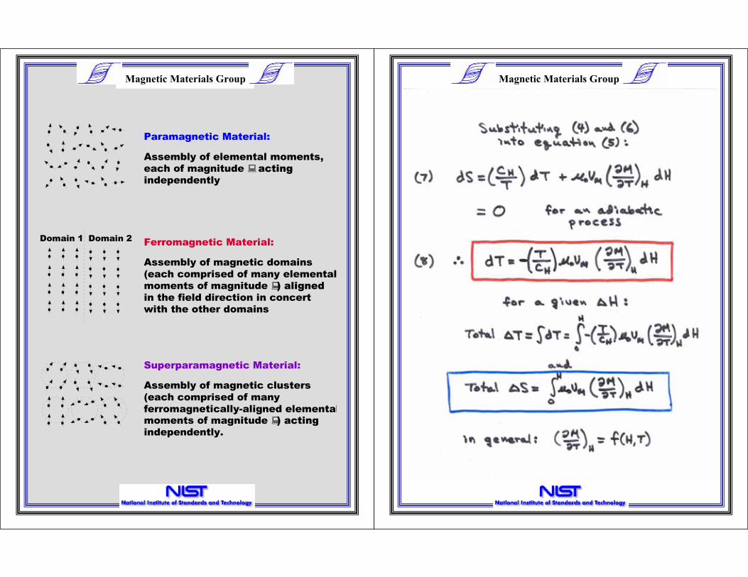
Domain 1 Domain 2
Paramagnetic Material:
Ferromagnetic Material:
Superparamagnetic Material:
Assembly of elemental moments,
each of magnitude acting
independently
Assembly of magnetic domains
(each comprised of many elemental
moments of magnitude ) aligned
in the field direction in concert
with the other domains
Assembly of magnetic clusters
(each comprised of many
ferromagnetically-aligned elementalmoments of magnitude ) acting
independently.

Magnetic Materials Group
VERY SMALL PARTICLE LIMIT
Paramagnetic Material:
Assembly of elemental moments,
each of magnitude , acting
independently
Magnetic Materials Group

Magnetic Materials Group
M = N 2H/3kBT
M/ T = -N 2H/3kBT2
T = -(T/CH) oVM( M/ T)H H
T = (1/CH) oVM(N 2H/3kBT) H
The temperature change for a paramagnet
Is inversely proportional to the temperature
And proportional to the field change.
Magnetic Materials Group
SMALL PARTICLE BEHAVIOR
Superparamagnetic Material:
Assembly of magnetic clusters
(each comprised of many
ferromagnetically-aligned elemental
independently.
moments of magnitude ) acting
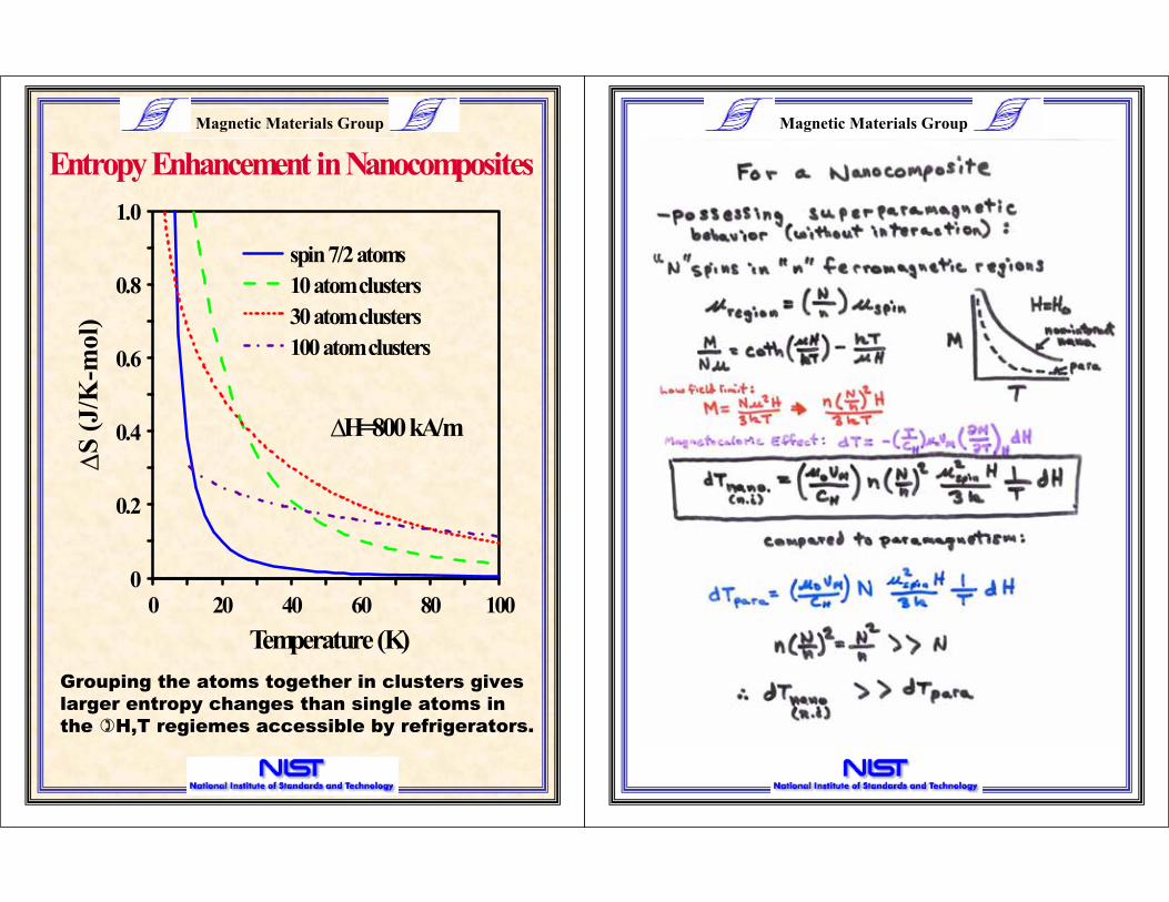
["The Magnetocaloric Effect in Nanocomposites", R. Shull,
L. Swartzendruber, L. Bennett, Proc. of the 6th Int’l.
Cryocoolers Conf., eds. G. Green, M. Knox, David Taylor
Res. Cntr. Publ. #DTRC-91/002, Annapolis, MD (1991) 231.]
Magnetic Materials GroupMagnetic Materials Group
0 20 40 60 80 100
1.0
0.8
0.6
0.4
0.2
0
spin 7/2 atoms
10 atom clusters
30 atom clusters
100 atom clusters
Temperature (K)
S (
J/K
-mol)
Entropy Enhancement in Nanocomposites
H=800 kA/m
Grouping the atoms together in clusters gives
larger entropy changes than single atoms in
the H,T regiemes accessible by refrigerators.
Magnetic Materials Group
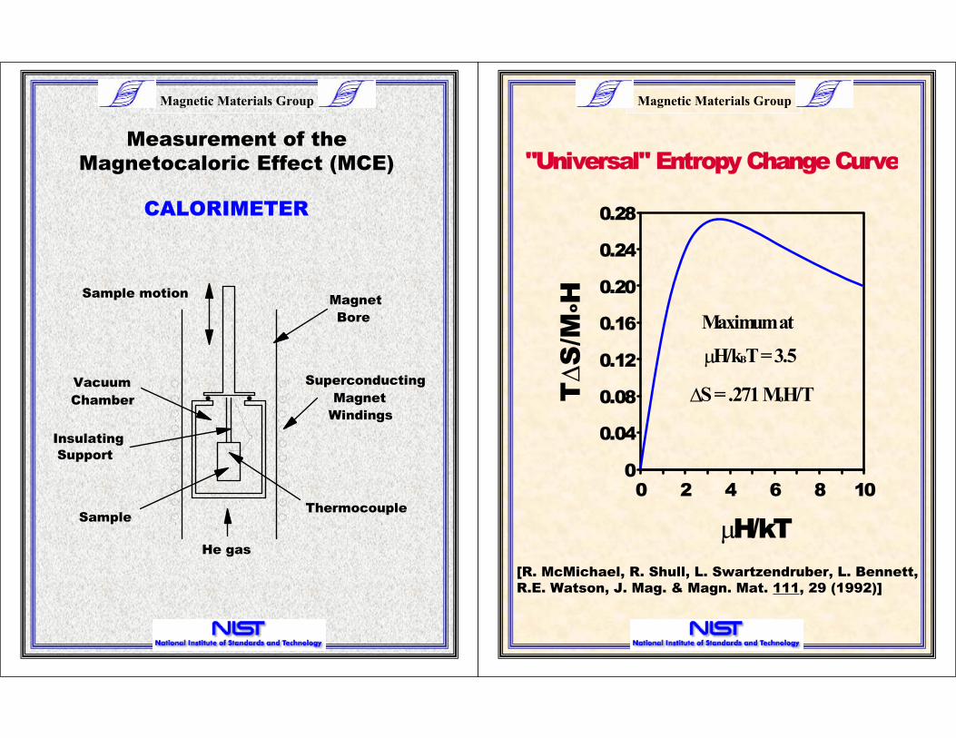
"Universal" Entropy Change Curve
0 2 4 6 8 10
H/kT
0.28
0.24
0.20
0.16
0.12
0.08
0.04
0
TS
/MoH
Maximum at
S = .271 MoH/T
H/kBT = 3.5
[R. McMichael, R. Shull, L. Swartzendruber, L. Bennett,
R.E. Watson, J. Mag. & Magn. Mat. 111, 29 (1992)]
Magnetic Materials Group
SampleThermocouple
Vacuum
Chamber
Superconducting
Magnet
Windings
Magnet
Bore
Insulating
Support
He gas
Sample motion
CALORIMETER
Measurement of the
Magnetocaloric Effect (MCE)
Magnetic Materials Group
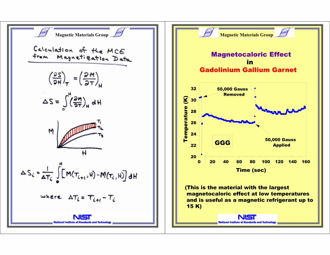
0 20 40 60 80 100 120 140 160
Time (sec)
Tem
pera
ture
(K
)
32
30
28
26
24
22
20
50,000 Gauss
Applied
50,000 Gauss
Removed
GGG
Magnetocaloric Effect
in
Gadolinium Gallium Garnet
(This is the material with the largest
magnetocaloric effect at low temperatures
and is useful as a magnetic refrigerant up to
15 K)
Magnetic Materials Group

Magnetic Materials Group
Magnetization Isotherms
(for Entropy Calculations)
Gd Ga O3 5 12
0 200 400 600
Applied Field (kA/m)
28
24
20
16
12
8
4
0
GGG 6 K
20 K
100 K
Ma
gn
eti
za
tio
n (
A-m
2/k
g)
Magnetic Materials Group
0 20 40 60 80 100
Temperature (K)
1.0
0.8
0.6
0.4
0.2
0
GGG
S (
J/K
-kg
)
Experiment
Calculated
(H=800 kA/m)
Magnetocaloric Effect
Gd Ga O3 5 12
Calculation of the MCE values from magnetization
data is a good way to determine MCE (& it is much
faster).

Magnetic Materials Group
Prepared nanocomposites by adding
aqueous solutions of the mixed metal
nitrates to excess tartaric acid (for
Air dried (200-325 C)
Samples characterized
X-ray diffraction
Mossbauer Effect
Ferromagnetic Resonance
Magnetic susceptibility
Formed Garnet Structure
(1) Air (950 C)
complexing)
Gd Ga Fe O3 5-x x 12
Bulk
Nanocomposites
Magnetic Materials Group
Schematic Picture of
Magnetic Nanocomposites
Gd Fe Ga
GarnetGd Ga Fe O5-x x 123-y
Fe spins create magnetic clusters (dashed areas)

Magnetic Materials Group
Magnetization Isotherms
(for Entropy Calculations)
Gd Ga O3 5 12
0 200 400 600
Applied Field (kA/m)
28
24
20
16
12
8
4
0
GGG 6 K
20 K
100 K
Ma
gn
eti
za
tio
n (
A-m
2/k
g)
Straight line isotherms show paramagnetic behavior
& therefore no interaction between magnetic spins
Magnetic Materials Group
0 200 400 600
60
50
40
30
20
10
0
Applied Field (kA/m)
Ma
gn
eti
za
tio
n (
A-m
2/k
g)
6 K20 K
50 K
Magnetization Isotherms
(for Entropy Calculations)
Gd Ga Fe O3 3.25 1.75 12
Curved isotherms show superparamagnetic behavior
& therefore the presence of magnetic clusters
Magnetic Materials Group
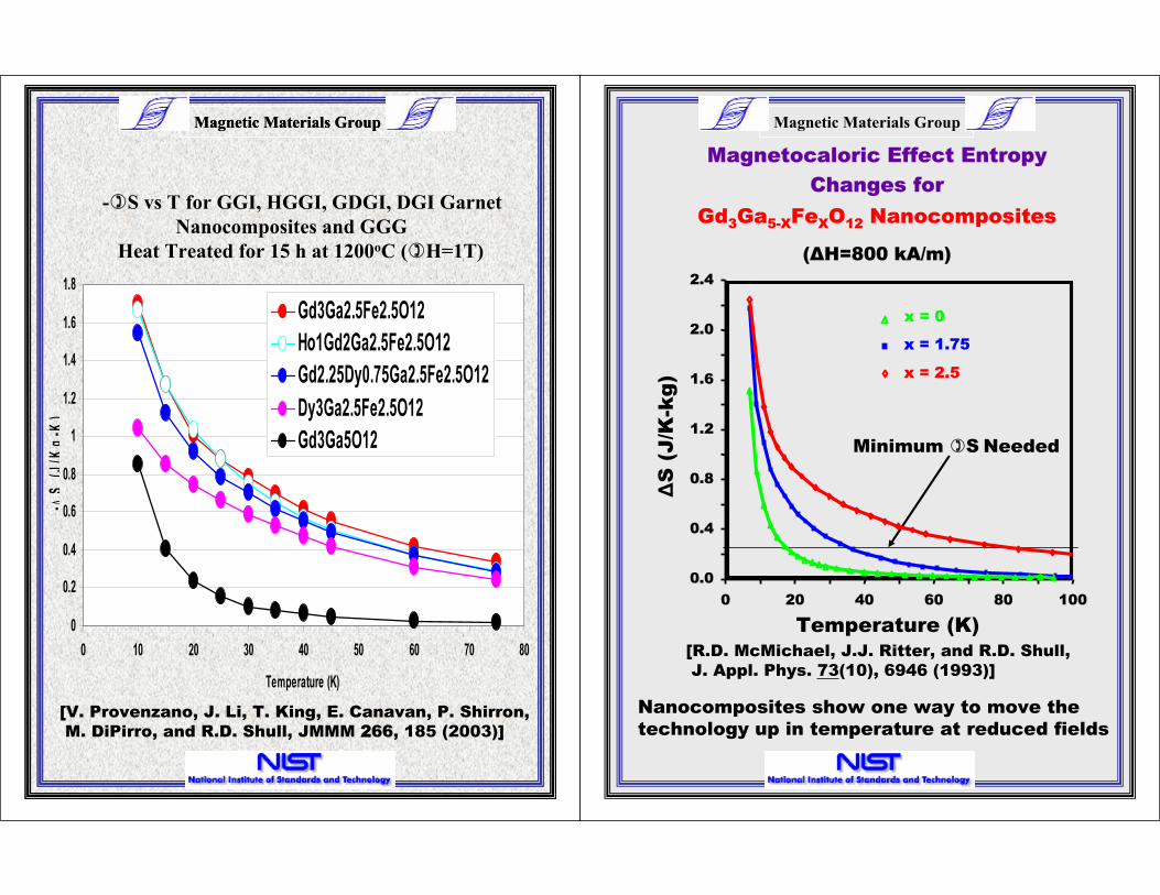
Nanocomposites show one way to move the
technology up in temperature at reduced fields
Magnetocaloric Effect Entropy
Changes for
Gd3Ga5-XFeXO12 Nanocomposites
( H=800 kA/m)
Minimum S Needed
0 20 40 60 80 100
2.4
2.0
1.6
1.2
0.8
0.4
0.0
Temperature (K)
x = 2.5
x = 1.75
x = 0
S (
J/K
-kg
)[R.D. McMichael, J.J. Ritter, and R.D. Shull,
J. Appl. Phys. 73(10), 6946 (1993)]
Magnetic Materials GroupMagnetic Materials Group
0
0.2
0.4
0.6
0.8
1
1.2
1.4
1.6
1.8
0 10 20 30 40 50 60 70 80
Temperature (K)
-S
(J/K
g-K
)
Gd3Ga2.5Fe2.5O12
Ho1Gd2Ga2.5Fe2.5O12
Gd2.25Dy0.75Ga2.5Fe2.5O12
Dy3Ga2.5Fe2.5O12
Gd3Ga5O12
- S vs T for GGI, HGGI, GDGI, DGI Garnet
Nanocomposites and GGG
Heat Treated for 15 h at 1200oC ( H=1T)
[V. Provenzano, J. Li, T. King, E. Canavan, P. Shirron,
M. DiPirro, and R.D. Shull, JMMM 2266, 185 (2003)]

Magnetic Materials Group
LARGE PARTICLE LIMIT
Domain 1 Domain 2
Ferromagnetic Material:
Assembly of magnetic domains
(each comprised of many elemental
in the field direction in concert
with the other domains
) alignedmoments of magnitude
Magnetic Materials Group

Magnetic Materials GroupMagnetic Materials Group
0
1
2
3
4
5
6
7
8
0 50 100 150 200 250 300
Temperature (K)
-S
(J/K
g-K
Heat Treated 3 THeat Treated 2 THeat Treated 1 TAs Cast 3 TAs Cast 2 TAs Cast 1 T
S vs T for Gd5Ge2Si2 : As-Cast and
Heat Treated (1100oC, 1 h + 1400oC, .2 h)
[V. Provenzano, A.J. Shapiro, and R.D. Shull,
Nature 4429, 853 (2004)]

Magnetic Materials Group
BEHAVIOR
Superferromagnetic Material:
Assembly of magnetic clusters
(each comprised of many
ferromagnetically-aligned elemental
in concert with other clusters.
moments of magnitude ) acting
INTERACTING SMALL-PARTICLE
Magnetic Materials Group
Magnetic Materials GroupMagnetic Materials Group
0 200 400 600
0.5
0.4
0.3
0.2
0.1
0
single atoms
10 atom clusters
100 atom clusters
Temperature (K)
S (
J/K
-mo
l)
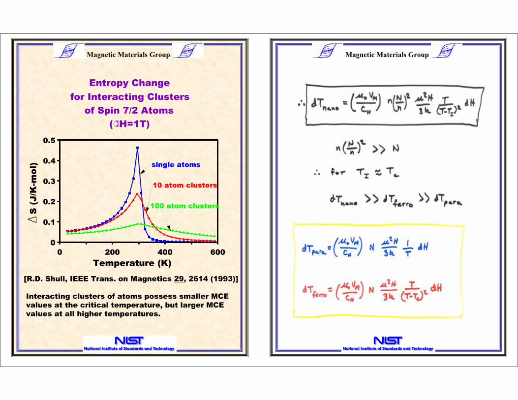
for Interacting Clusters
of Spin 7/2 Atoms
( H=1T)
Entropy Change
Interacting clusters of atoms possess smaller MCE
values at the critical temperature, but larger MCE
values at all higher temperatures.
[R.D. Shull, IEEE Trans. on Magnetics 29, 2614 (1993)]

Magnetic Materials Group
WHAT ABOUT MCE CALCULATION
FOR A FERROMAGNET???
M is NOT a Single Valued Function!
M is No Longer a Good Order Parameter !!!
Hysteresis Loss NEEDS to be subtracted
from the MCE!!!
[V. Provenzano, A.J. Shapiro, and R.D. Shull,
Nature 4429, 853 (2004); V. Provenzano, B. Baumgold,
R.D. Shull, A.J. Shapiro, K. Koyama, K. Watanabe,
N.K. Singh, K.G. Suresh, A.K. Nigam, and S.K. Malik,
J. Appl. Phys. 999, 08K906 (2006)]
Magnetic Materials Group
This is a good way to vary the magnetic field from
a permanent magnet in a compact volume.
Perhaps for a magnetic refrigerator???
Magnetic Materials Group
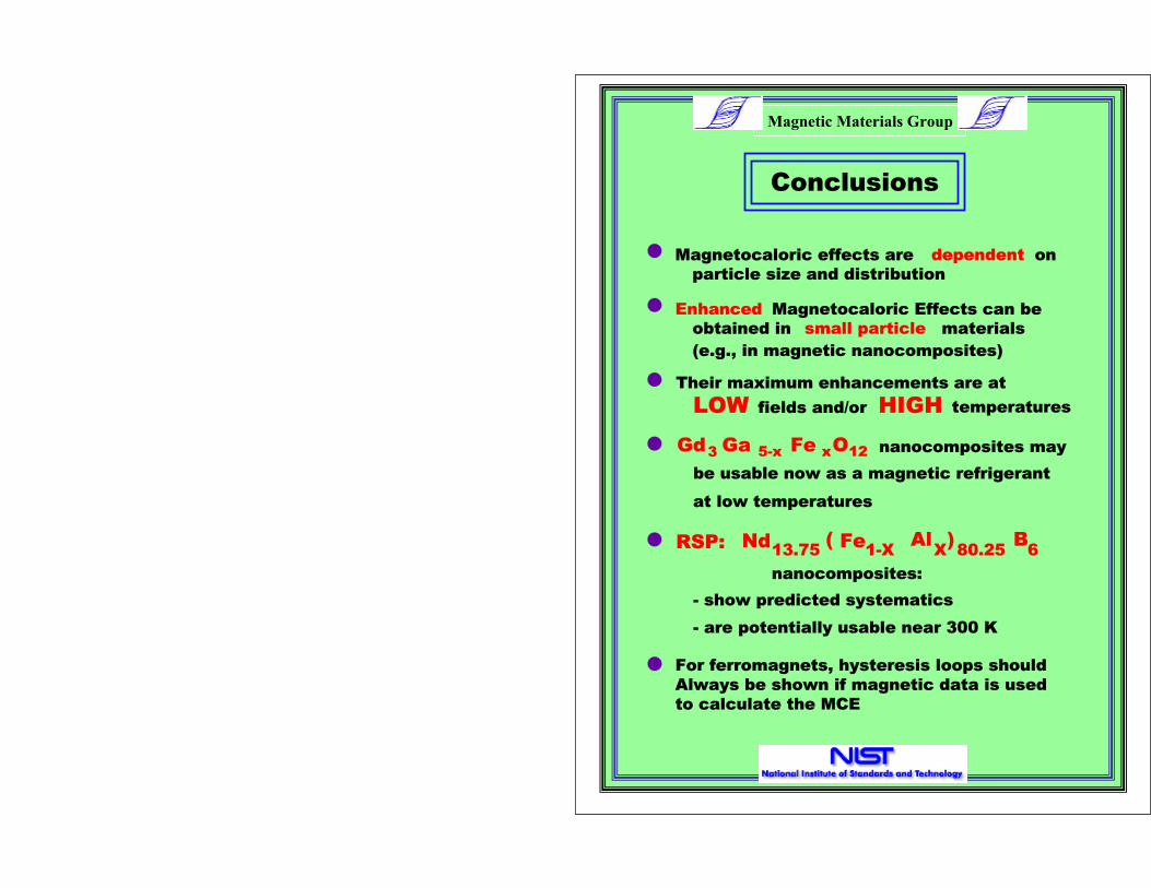
nanocomposites:
- show predicted systematics
Nd Fe Al B1-X X
)(13.75 80.25 6RSP:
- are potentially usable near 300 K
Conclusions
particle size and distribution
dependent onMagnetocaloric effects are
(e.g., in magnetic nanocomposites)
Enhanced Magnetocaloric Effects can be
small particle materialsobtained in
be usable now as a magnetic refrigerant
at low temperatures
nanocomposites mayGd Ga Fe O3 5-x x 12
Their maximum enhancements are at
LOW fields and/or HIGH temperatures
For ferromagnets, hysteresis loops should
Always be shown if magnetic data is used
to calculate the MCE