NanoElectro Mechanical Systems (NEMS)
44
Nano Electro Mechanical Systems (NEMS) and interactions at nanoscale Alessandro Siria : Institut Néel-CNRS Grenoble CEA-LETI/MINATEC Grenoble Advisors: Joel Chevrier , UJF and CNRS Grenoble Hubert Grange , CEA-LETI/MINATEC Grenoble
Transcript of NanoElectro Mechanical Systems (NEMS)
Nano Electro Mechanical Systems (NEMS)
and
interactions at nanoscale
Alessandro Siria:
Institut Néel-CNRS Grenoble
CEA-LETI/MINATEC Grenoble Advisors:
Joel Chevrier, UJF and CNRS Grenoble
Hubert Grange, CEA-LETI/MINATEC Grenoble

Nano Electro Mechanical Systems (NEMS)
NEMS are devices integrating electrical and
mechanical functionalities at the nanoscale.
NEMS are among the best candidates for
measurement of interactions at nanoscale
2
Frequency
NEMS resonators can be assimilated
to harmonic oscillators
( ) ( ) γωωωωχ
im +−=
22
0
1
Am
plit
ude P
hase

Interactions at nanoscale
NEMS standard scheme:
• Mobile part suspended over a fixed substrate;
• Gap from tens nanometers to several microns;
• Plane-Plane geometry.
Gap
3
Interactions between mobile and fixed parts can dominate the NEMS
dynamics
• Chemical forces;
• Van der Waals and Casimir forces
• Electrostatic (residual) forces;
• Optical forces;
• Hydrodynamic forces;
• Near field thermal radiation.
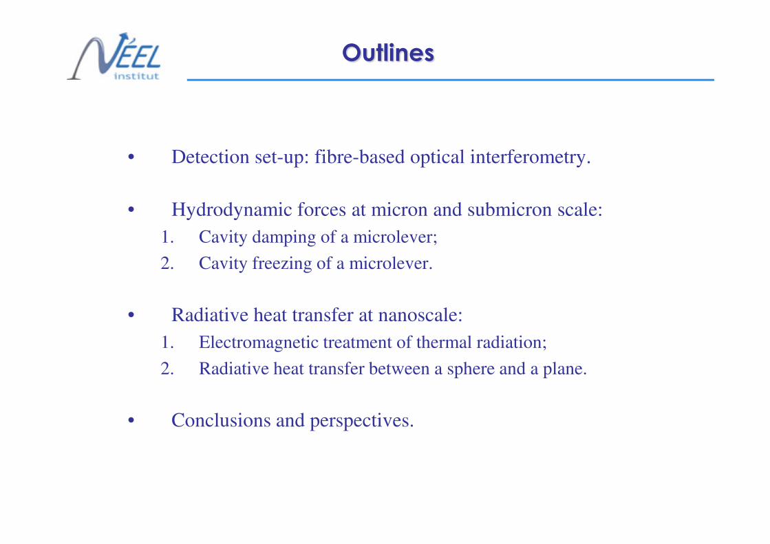
Outlines
• Detection set-up: fibre-based optical interferometry.
• Hydrodynamic forces at micron and submicron scale:
1. Cavity damping of a microlever;
2. Cavity freezing of a microlever.
4
2. Cavity freezing of a microlever.
• Radiative heat transfer at nanoscale:
1. Electromagnetic treatment of thermal radiation;
2. Radiative heat transfer between a sphere and a plane.
• Conclusions and perspectives.

X-ray and Mechanical Systems
OPTICAL FORCES
Interaction between X-ray and Mechanical systems:
1) Mechanical effect of X-ray beam;
2) MEMS based X-ray chopper.
5
European Synchrotron Radiation Facility
@ Surface Science Laboratory (SSL)
In collaboration with
Fabio Comin
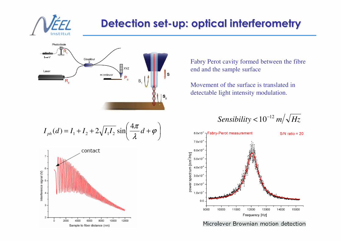
Detection set-up: optical interferometry
Fabry Perot cavity formed between the fibre
end and the sample surface
Movement of the surface is translated in
detectable light intensity modulation.
HzmySensibilit1210−<
6
+++= ϕ
λ
πdIIIIdI ph
4sin2)( 2121
HzmySensibilit 10<
Hydrodynamic forces at
7
Hydrodynamic forces at
micron and sub-micron scale
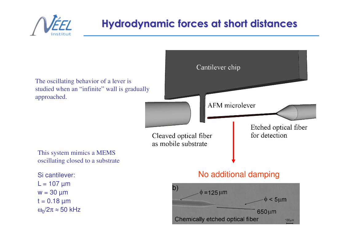
Hydrodynamic forces at short distances
The oscillating behavior of a lever is
studied when an “infinite” wall is gradually
approached.
8
This system mimics a MEMS
oscillating closed to a substrate
Si cantilever:
L = 107 µm
w = 30 µm
t = 0.18 µm
ω0/2π ≈ 50 kHz
No additional damping

Hydrodynamic forces at short distances
The lever is thermally actuated.
With decreasing gap in micrometer range we
observe a broadening and softening of
fundamental resonance.
9
( )( ) γωωω
ωχim +−
=
22
0
1Driven and damped 1D oscillator
Damping of lever studied
recording resonance quality
factorγωω
ω
0
kQ
res
=∆
=
-γγγγV-Kx

Broadening: Softening:
Experimental results
10
Micrometric lenght scale:
mdL µ20≈
Confinement effect
Nanometric lenght scale:
nmdC 400≈
Freeezing of resonance

Cavity damping of the oscillator
γω0
kQ =
Large gap: damping independent on distance
Small gap : damping depending on inverse of distance
11
Theoretical description based on Navier-Stokes equation
Boundary conditions control the agreement theory - experiments
Which boundary conditions??
Reynold’s number:
pvt
v∇−∇=
∂
∂ rr
2ηρ
46 1010Re −− ÷≈⋅⋅
=η
ρdvLAMINAR REGIME

Boundary layer definition:
At lever resonance:
ρω
η2=Ld
mdL µ20≈
Confinement characteristic length
Spatial region surrounding the lever where
12
viscosity dominates the fluid behavior
pv
dd L
∇=∇
⇒<<r2η2
22
2
Ld
dd
v
t
v
≈≈∇
∂
∂
η
ρω
η
ρ
r
r
Inertial << Viscosity

Perfect slip boundary conditions
( )( )xfv
zgv
x
z
=
=
Perfect slip at fluid-solid interface:
13
d
Aηγ
2=
dA
kQ
02 ωη= Linear dependency of the quality factor with the gap size.
Consistent with experimental evidence
2
2
2
2
z
v
z
p
x
v
x
p
z
x
∂
∂=
∂
∂
∂
∂=
∂
∂
η
η
zz Ud
AF
η2−=Navier-Stokes equation
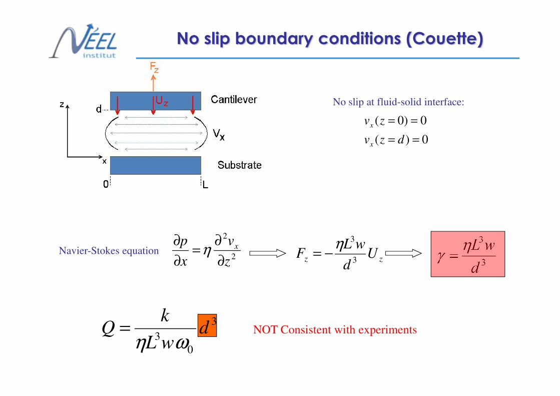
No slip boundary conditions (Couette)
0)(
0)0(
==
==
dzv
zv
x
x
No slip at fluid-solid interface:
14
3
3
d
wLηγ =
3
0
3d
wL
kQ
ωη= NOT Consistent with experiments
2
2
z
v
x
p x
∂
∂=
∂
∂η
zz Ud
wLF
3
3η−=Navier-Stokes equation
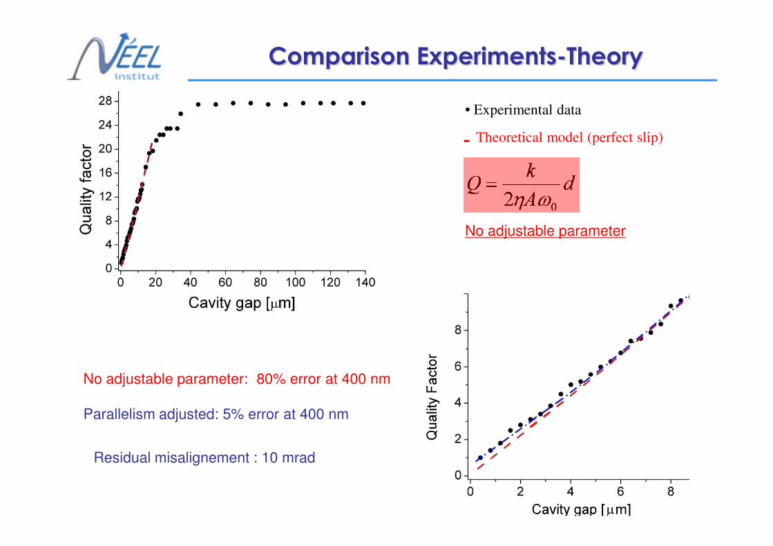
• Experimental data
Theoretical model (perfect slip)
Comparison Experiments-Theory
No adjustable parameter
dA
kQ
02 ωη=
15
No adjustable parameter: 80% error at 400 nm
Parallelism adjusted: 5% error at 400 nm
Residual misalignement : 10 mrad

Cavity freezing of the oscillator
In the limit of large damping the oscillator has a
down-shift of the resonance
No adjustable parameter
Parallelism adjusted: 10 mrad
16
02
0
=′⇔= ωω
η A
mGapcrit
If the gap is small enough air confinement can
eventually freeze the mechanical oscillator

Hydrodynamic forces: summary
Cantilever dynamics modified by fluid confinement
according to Navier-Stokes equation;
17
Perfect slip at fluid-solid interface induces a long
range hydrodynamic force: F 1/d
For nanometre size cavity the lever oscillation can
be freezed because of the fluid confinement.

Near – Field radiative
18
Near – Field radiative
heat transfer

Electromagnetic treatment.
Fluctuating dipole
induced by thermal effect
FAR-FIELD: propagative waves
Independent by distance
19
NEAR-FIELD: evanescent waves
Strongly dependent by distance

Dielectric materials: surface Phonon-
Polariton enhancement effect
Surface waves: described by dielectric constant ε(ω)
E
p
20
Infra-red resonance
(SiC, quartz, alumine, silica, Si doped)
Radiative thermal transfer
increased by the resonance effect

Dielectric materials: surface Phonon-
Polariton enhancement effect
Density of energy near a SiC-vacuum interface
Far field: the energy density well
reproduces the Plank black body theory
21
Near field: the energy density exceeds
the Plank black body theory:
Monochromatic thermal emission and
exponential decay with the distance
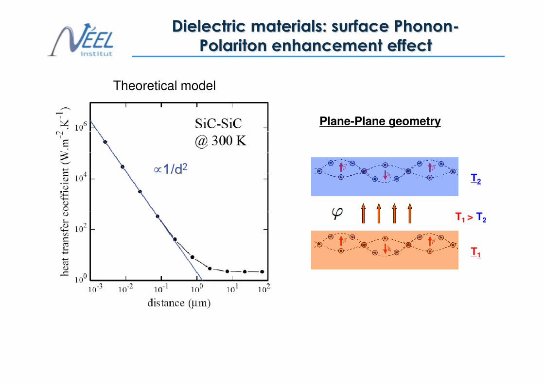
Dielectric materials: surface Phonon-
Polariton enhancement effect
T2
Plane-Plane geometry
Theoretical model
22
T1
T1 > T2

Plane-plane geometry: experimental issue
d d
23
Plane-Plane
Theory developed
BUT
Experiments very difficult
Plane-sphere
Experimentally possible
BUT
Theory not yet developed

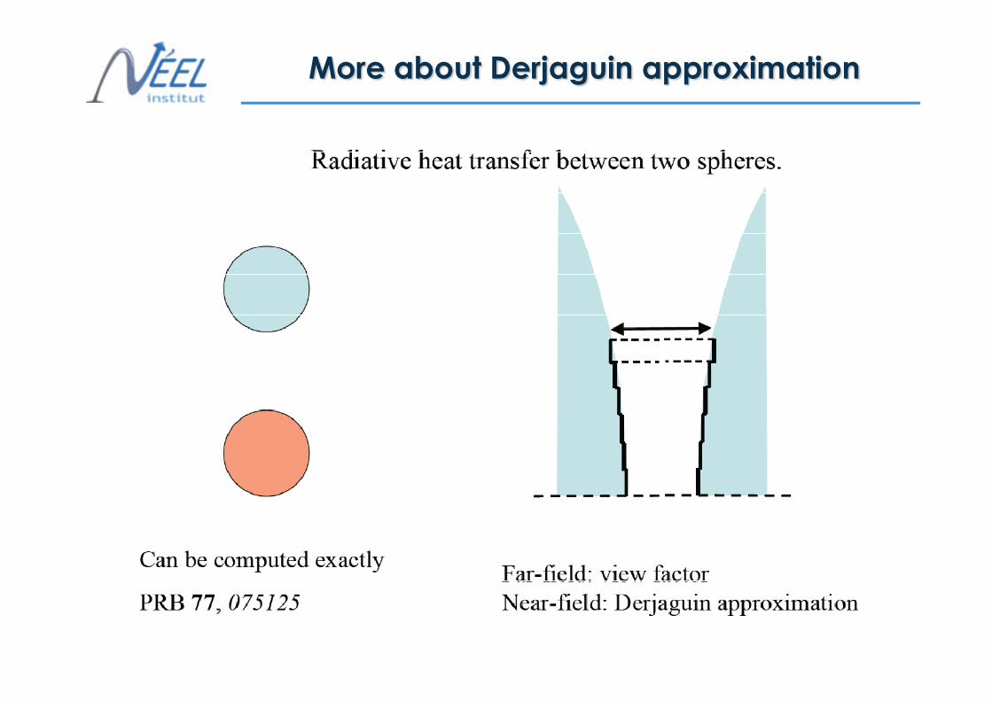
Sphere-Plane geometry: theory
Sphere-Plane geometry
24Proximity force approximation
d
d

Sphere-Plane geometry: theory
d
d
25Proximity force approximation
Far field Far field

Switch to radiative heat transfer measurement…
What we want to measure
26
How we want to measure

Experimental set-up
Optical fiber
27
- Power exchanged = lever deflection : thermal switch effect on the lever
- High vacuum P~10-6 mbar : conduction neglegible
- ∆T = 10-20 K.

Experimental raw data
Calibration ???
28
Contact definition ???

Fluxmeter calibration
29
nmnWH
H
/ 03.2=
⋅= δϕ
δ

Surface roughness
Contact between plate and
sphere asperity
Average surface contact
shifted repect hard contact
30
From SEM image sphere
roughness:
50 nm rms

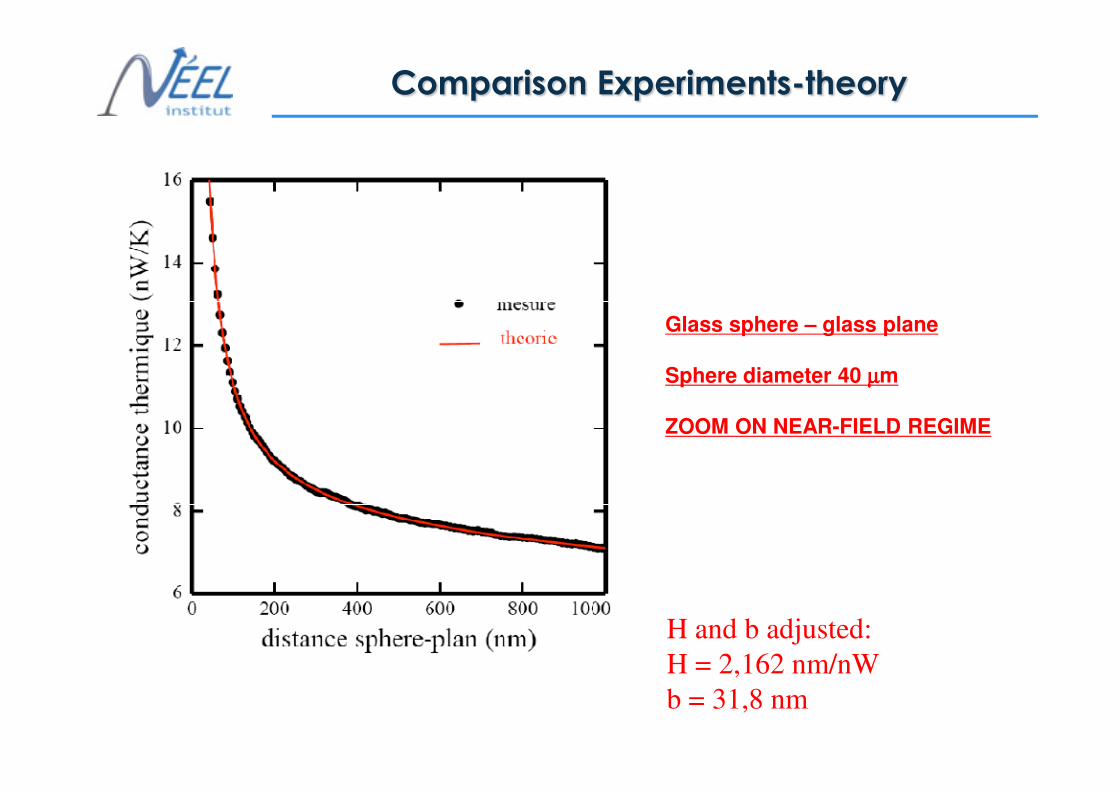
Comparison Experiments-theory
Glass sphere – glass plane
Sphere diameter 40 µµµµm
31
H and b adjusted:
H = 2,162 nm/nW
b = 31,8 nm
Glass sphere – glass plane
Sphere diameter 40 µµµµm
Comparison Experiments-theory
32
ZOOM ON NEAR-FIELD REGIME
H and b adjusted:
H = 2,162 nm/nW
b = 31,8 nm

Conclusions
Development of experimental set-up for the radiative
thermal transfer
33
Relative comparison theory-experience with
4% indetermination
Precise measurement heat transfer in 50nm-5um range
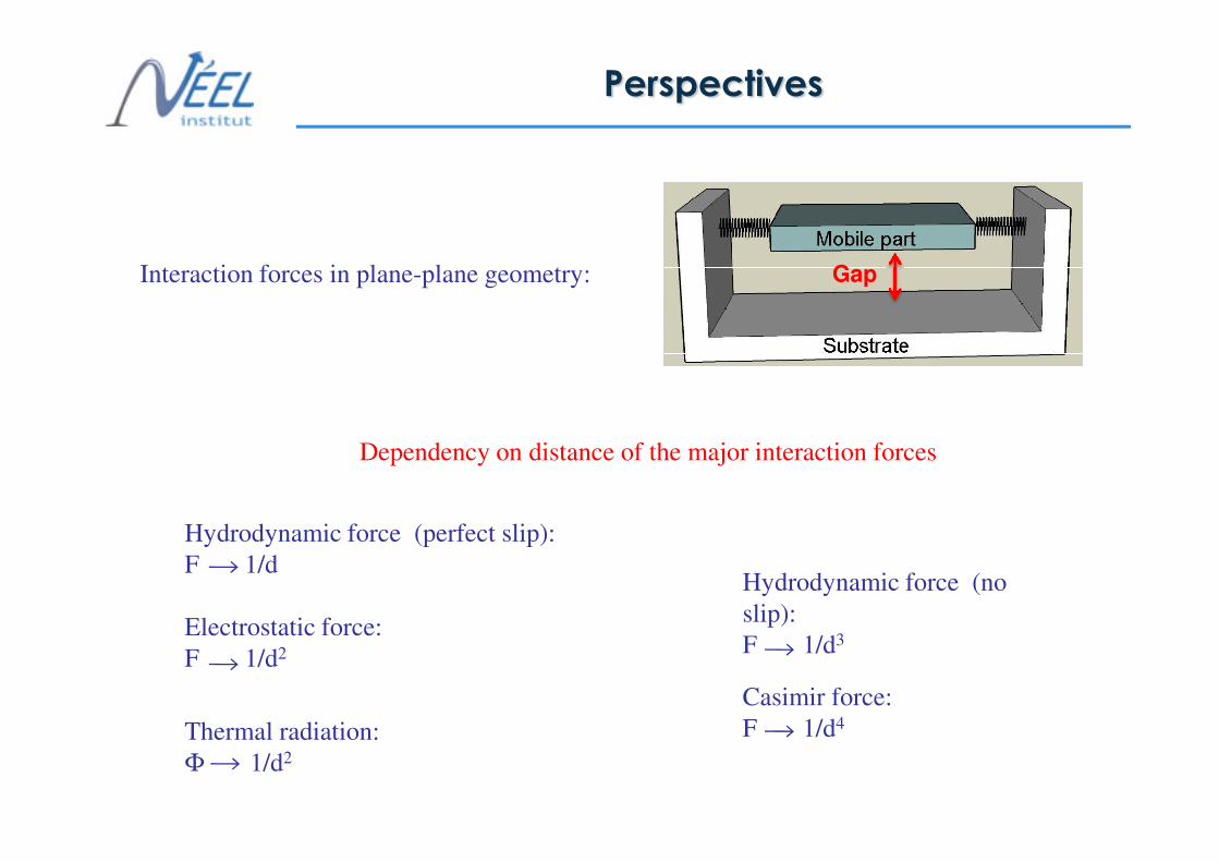
Perspectives
Interaction forces in plane-plane geometry: Gap
34
Hydrodynamic force (perfect slip):
F 1/d
Electrostatic force:
F 1/d2
Thermal radiation:
Φ 1/d2
Hydrodynamic force (no
slip):
F 1/d3
Casimir force:
F 1/d4
Dependency on distance of the major interaction forces

Set-up
Misalignment correction
Attocube inertial motor goniometer:
10-4 deg
35
Focused Ion Beam sample realization
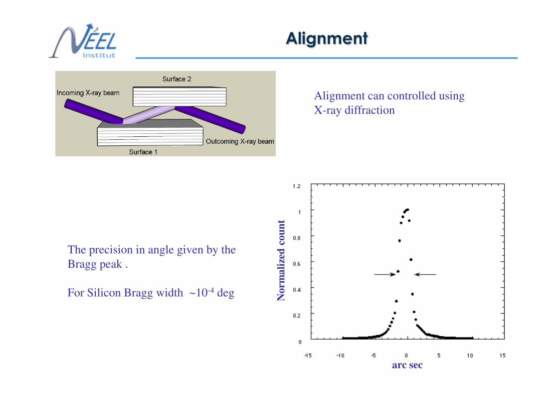
Alignment
Alignment can controlled using
X-ray diffraction
36
The precision in angle given by the
Bragg peak .
For Silicon Bragg width ~10-4 deg
arc sec
No
rma
lize
d c
ou
nt

What happens at large gap?
Damping of the lever is not depending
on distance:
WHY?
Coming back to NS equation:
v ∂r
37
Boundary layer definition:ρω
η2=Ld v
t
vdd L
rr
2∇>>
∂
∂⇒>> ηρ
Damping should saturate
pvt
v∇−∇=
∂
∂ rr
2ηρ

Theory: electromagnetic treatment.
Green Tensor formalism:
Fluctuation-dissipation theorem:
( ) ( ) ( ) ( ) ( ) ( )'',''2',', ,0*
ωωδδδωωεπ
ωεωω −−Θ= rrTrjrj nm
f
n
f
m
rrrr
( ) ( ) ( ) ( )
( ) ( ) ( )ωωω
ωωωµω
,',',,
,',',, 0
rjrrGrH
rjrrGirE
fH
fE
rrrrtrr
rrrrtrr
⋅=
⋅=
38
Electromagnetic energy density:
( ) ( ) ( ) ( ) ( )
( ) ( ) ( ) ( )[ ]( ) ( ) ( )[ ]∫
∫
∞−+
Θ+
+−+−Θ
=
⋅+⋅=
0
0
0
''2
0
3
0
3
22
2
0
22
00
22
2
*0*0
ImIm2
1,
112
1,
4
1,,
,,2
,,2
,,
k
z
ps
k
ps
errk
dKK
c
T
rrk
KdK
c
Ttzu
rHrHrErEtru
γ
γπ
ωω
γπ
ωωω
ωωµ
ωωε
ω
rrrrrrrrr

More about Derjaguin approximation
39

More about Derjaguin approximation
40
More about Derjaguin approximation
41

Spheres radius: 20 µm
42

43
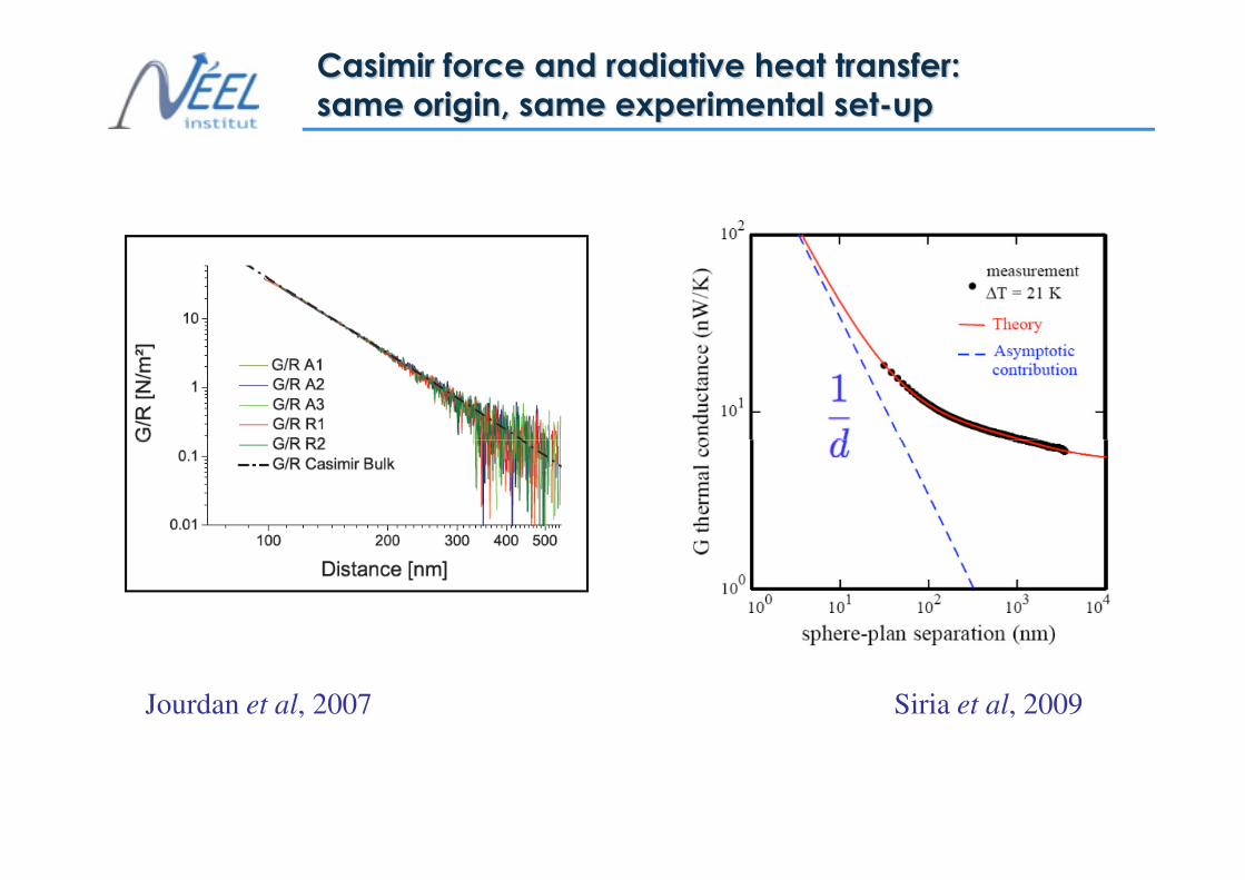
Casimir force and radiative heat transfer:
same origin, same experimental set-up
44
Siria et al, 2009Jourdan et al, 2007


![NEMS ACTUATOR DRIVEN BY OPTICAL GRADIENT FORCE€¦ · power consumption [8]. In this letter, a NEMS optical actuator is demonstrated, where the mechanical beam is actuated by optical](https://static.fdocuments.us/doc/165x107/5f30d22360b9bc3e3840f804/nems-actuator-driven-by-optical-gradient-force-power-consumption-8-in-this-letter.jpg)


![A Novel Silicon-based Wideband Nano Switch For RF Applications€¦ · wireless communication system [2]. The emerging - Nano Electro-Mechanical-Systems (NEMS) technology is expected](https://static.fdocuments.us/doc/165x107/5e8fa1a758b3860e692fcb39/a-novel-silicon-based-wideband-nano-switch-for-rf-applications-wireless-communication.jpg)