NanaWall HSW60 - Thermally Broken Aluminum Framed Single ... · NanaWall HSW60 - Thermally Broken...
26
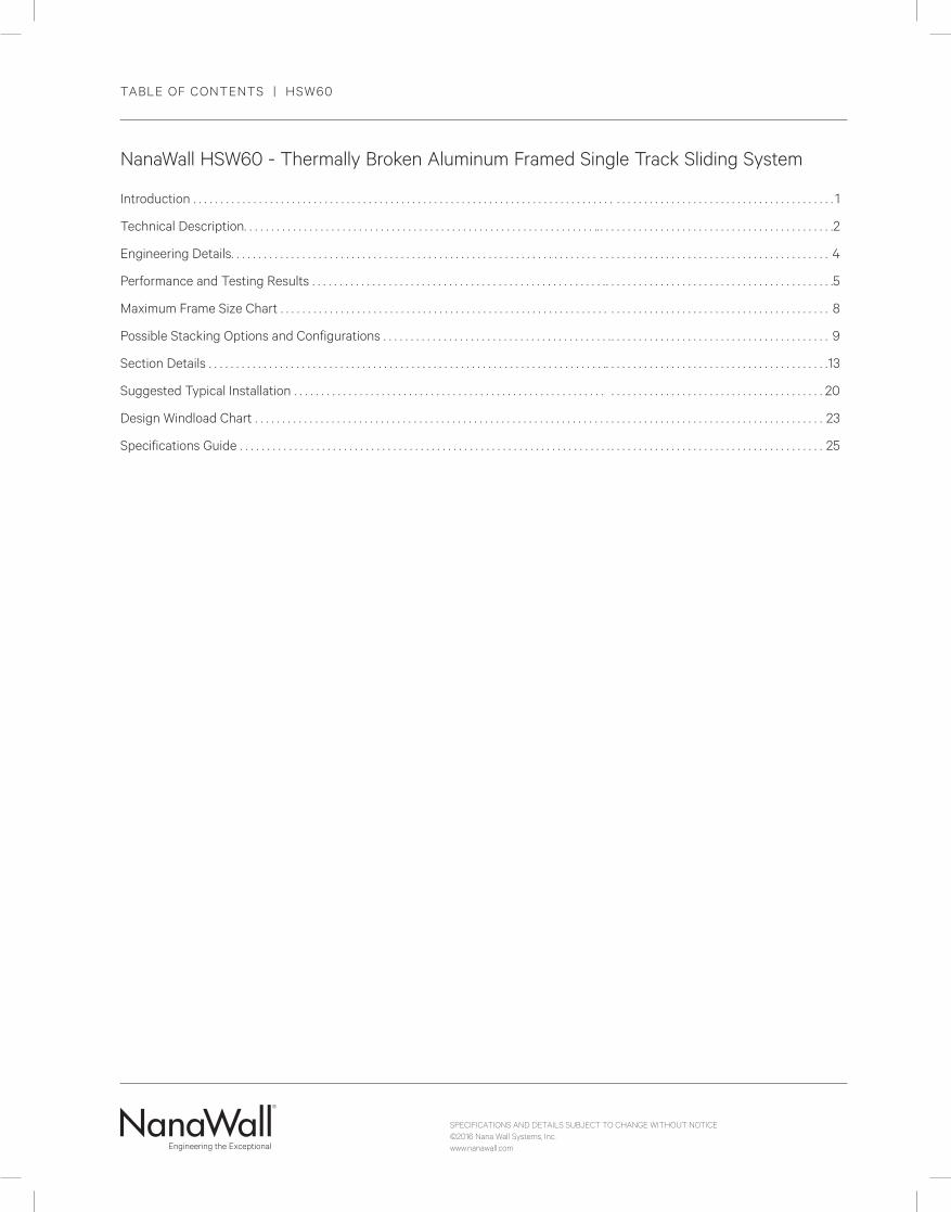
SPECIFICATIONS AND DETAILS SUBJECT TO CHANGE WITHOUT NOTICE ©2016 Nana Wall Systems, Inc. www.nanawall.com NanaWall HSW60 - Thermally Broken Aluminum Framed Single Track Sliding System Introduction . . . . . . . . . . . . . . . . . . . . . . . . . . . . . . . . . . . . . . . . . . . . . . . . . . . . . . . . . . . . . . . . . . . . . . . . . . . . . . . . . . . . . . . . . . . . . . . . . . . . . . . . . . . . . . . . . . . . . 1 Technical Description. . . . . . . . . . . . . . . . . . . . . . . . . . . . . . . . . . . . . . . . . . . . . . . . . . . . . . . . . . . . . . . . .. . . . . . . . . . . . . . . . . . . . . . . . . . . . . . . . . . . . . . . . . . . . 2 Engineering Details. . . . . . . . . . . . . . . . . . . . . . . . . . . . . . . . . . . . . . . . . . . . . . . . . . . . . . . . . . . . . . . . . . . . . . . . . . . . . . . . . . . . . . . . . . . . . . . . . . . . . . . . . . . . . 4 Performance and Testing Results . . . . . . . . . . . . . . . . . . . . . . . . . . . . . . . . . . . . . . . . . . . . . . . . . . . . . .. . . . . . . . . . . . . . . . . . . . . . . . . . . . . . . . . . . . . . . . . .5 Maximum Frame Size Chart . . . . . . . . . . . . . . . . . . . . . . . . . . . . . . . . . . . . . . . . . . . . . . . . . . . . . . . . . . . . . . . . . . . . . . . . . . . . . . . . . . . . . . . . . . . . . . . . . . . . 8 Possible Stacking Options and Configurations . . . . . . . . . . . . . . . . . . . . . . . . . . . . . . . . . . . . . . . . . . . . . . . . . . . . . . . . . . . . . . . . . . . . . . . . . . . . . . . . . . 9 Section Details . . . . . . . . . . . . . . . . . . . . . . . . . . . . . . . . . . . . . . . . . . . . . . . . . . . . . . . . . . . . . . . . . . . . . . . . .. . . . . . . . . . . . . . . . . . . . . . . . . . . . . . . . . . . . . . . . . 13 Suggested Typical Installation . . . . . . . . . . . . . . . . . . . . . . . . . . . . . . . . . . . . . . . . . . . . . . . . . . . . . . . . . . . . . . . . . . . . . . . . . . . . . . . . . . . . . . . . . . . . . . . . 20 Design Windload Chart . . . . . . . . . . . . . . . . . . . . . . . . . . . . . . . . . . . . . . . . . . . . . . . . . . . . . . . . . . . . . . . . . . . . . . . . . . . . . . . . . . . . . . . . . . . . . . . . . . . . . . . . 23 Specifications Guide . . . . . . . . . . . . . . . . . . . . . . . . . . . . . . . . . . . . . . . . . . . . . . . . . . . . . . . . . . . . . . . . . . . . . . . . . . . . . . . . . . . . . . . . . . . . . . . . . . . . . . . . . . . 25 TABLE OF CONTENTS | HSW60
-
Upload
dinhnguyet -
Category
Documents
-
view
221 -
download
1
Transcript of NanaWall HSW60 - Thermally Broken Aluminum Framed Single ... · NanaWall HSW60 - Thermally Broken...
SPECIFICATIONS AND DETAILS SUBJECT TO CHANGE WITHOUT NOTICE©2016 Nana Wall Systems, Inc.www.nanawall.com
NanaWall HSW60 - Thermally Broken Aluminum Framed Single Track Sliding System
Introduction . . . . . . . . . . . . . . . . . . . . . . . . . . . . . . . . . . . . . . . . . . . . . . . . . . . . . . . . . . . . . . . . . . . . . . . . . . . . . . . . . . . . . . . . . . . . . . . . . . . . . . . . . . . . . . . . . . . . . 1
Technical Description. . . . . . . . . . . . . . . . . . . . . . . . . . . . . . . . . . . . . . . . . . . . . . . . . . . . . . . . . . . . . . . . .. . . . . . . . . . . . . . . . . . . . . . . . . . . . . . . . . . . . . . . . . . . .2
Engineering Details. . . . . . . . . . . . . . . . . . . . . . . . . . . . . . . . . . . . . . . . . . . . . . . . . . . . . . . . . . . . . . . . . . . . . . . . . . . . . . . . . . . . . . . . . . . . . . . . . . . . . . . . . . . . . 4
Performance and Testing Results . . . . . . . . . . . . . . . . . . . . . . . . . . . . . . . . . . . . . . . . . . . . . . . . . . . . . . . . . . . . . . . . . . . . . . . . . . . . . . . . . . . . . . . . . . . . . . . .5
Maximum Frame Size Chart . . . . . . . . . . . . . . . . . . . . . . . . . . . . . . . . . . . . . . . . . . . . . . . . . . . . . . . . . . . . . . . . . . . . . . . . . . . . . . . . . . . . . . . . . . . . . . . . . . . . 8
Possible Stacking Options and Configurations . . . . . . . . . . . . . . . . . . . . . . . . . . . . . . . . . . . . . . . . . . . . . . . . . . . . . . . . . . . . . . . . . . . . . . . . . . . . . . . . . . 9
Section Details . . . . . . . . . . . . . . . . . . . . . . . . . . . . . . . . . . . . . . . . . . . . . . . . . . . . . . . . . . . . . . . . . . . . . . . . .. . . . . . . . . . . . . . . . . . . . . . . . . . . . . . . . . . . . . . . . .13
Suggested Typical Installation . . . . . . . . . . . . . . . . . . . . . . . . . . . . . . . . . . . . . . . . . . . . . . . . . . . . . . . . . . . . . . . . . . . . . . . . . . . . . . . . . . . . . . . . . . . . . . . . 20
Design Windload Chart . . . . . . . . . . . . . . . . . . . . . . . . . . . . . . . . . . . . . . . . . . . . . . . . . . . . . . . . . . . . . . . . . . . . . . . . . . . . . . . . . . . . . . . . . . . . . . . . . . . . . . . . 23
Specifications Guide . . . . . . . . . . . . . . . . . . . . . . . . . . . . . . . . . . . . . . . . . . . . . . . . . . . . . . . . . . . . . . . . . . . . . . . . . . . . . . . . . . . . . . . . . . . . . . . . . . . . . . . . . . . 25
TABLE OF CONTENTS | HSW60

SPECIFICATIONS AND DETAILS SUBJECT TO CHANGE WITHOUT NOTICE©2016 Nana Wall Systems, Inc.www.nanawall.com
2

SPECIFICATIONS AND DETAILS SUBJECT TO CHANGE WITHOUT NOTICE©2016 Nana Wall Systems, Inc.www.nanawall.com
1
Unique Features
The thermally broken aluminum framed NanaWall HSW60 is an exterior, weather-resistant single track sliding system that provides the ultimate in versatility and flexibility. This is a storefront and entrance system that can easily and efficiently slide with a minimum of force completely out of-sight when desired, offering designers new possibilities for large, exterior opening glass walls. To see these operable wall concepts in action, please visit www.nanawall.com and click on the “Animations” link on the HSW60 page.
For benefits of all NanaWall systems, see the “General Introduction” section. For common features and a comparison between aluminum individual panel systems, see the “Aluminum Single Track Sliding Systems” Introduction.
Sizes
Unit Heights of up to 12’ (3650 mm) and panel widths of up to 5’ (1525 mm) are possible.
No horizontal mullion needed for unit heights of up to 10’ (3050 mm).
Incorporated swing panel with panel heights of up to 9’2” (2800 mm) possible, with many choices on position of incorporated swing panels in the opening and designed for use as a “normal” commercial egress door.
Single Hand Easy Operation In/Out of Stacking Bay
With an intelligent guide system, most panels self-guide through the switches for easy operation and stacking using sintered Bronze Carrier rollers and guided switches.
Incorporated Swing Entry/Exit Panel(s)
If desired, almost every sliding panel in the closed position can be converted and be used as an incorporated single acting swing panel. A pair of incorporated swing panels allows the possibility that either panel can be opened first. Swing panels can open inward or outward. The incorporated entrance doors have been engineered for “normal” commercial traffic and have been independently tested to half a million opening and closing cycles per AAMA 920.
Florida Approval
The HSW60 has received statewide Florida approval with Product Approval number 17751. This information with limitations can be viewed at www.floridabuilding.org.
Floor Track Optional
For certain applications, sills can be eliminated completely – providing seamless transition between two spaces. Locking rods in panels engage in adjustable floor sockets.
Multiple Stacking Options
The sliding storefront can be completely out-of-sight during business hours. The tracks can be laid out beyond the frame in a variety of configurations, and the stacking bays can be positioned anywhere along the track. The two carrier suspension system permits the use of track with right-angle turns and segmented curves, allowing multiple options for space set-up and remote storage.
Multiple Space Set-up
Using the same panels with additional parallel and perpendicular tracks will expand or reduce heated or air conditioned spaces with ease and convenience.
Right Turns and Segmented Curved Walls
With an ingenious, variable angle astragal profile, systems can be supplied with any segmented angle between 0º and 90º between panels, allowing the designer to create completely open corners or bays. Panels can turn corners.
Design Flexibility
Custom sizes of 5’ (1525 mm) are possible. Individual panels can be designed with different widths, glazing choices (double and triple insulated glass, laminated glass, etc.) and muntin layouts (horizontal mullions, SDLs, solid panels, higher bottom rails, etc.).
NanaWall HSW60 The Thermally Broken Aluminum Framed Single Track Sliding System
INTRODUCTION | HSW60

SPECIFICATIONS AND DETAILS SUBJECT TO CHANGE WITHOUT NOTICE©2016 Nana Wall Systems, Inc.www.nanawall.com
2
Weather Resistant
The system is engineered to provide weather resistance, high structural load performance, and resistance to dust infiltration.
NFRC Rated Thermal Performance
The HSW60 has been rated, certified and labeled in accordance with NFRC 100 and NFRC 200; see the “Performance and Testing Results” section for more details. A 2015 Energy Star Qualification Criteria: U-Factor for doors in all climate zones <.30, Shgc <25 in South/South central zones and <.40 in North/North Central zones. (For guidance only. NanaWall is not a participant of the Energy Star program.)
Superior Thermal Break
Panels thermally broken with a 7/8” (22 mm) polyamide plastic reinforced with glass fibers. This thermal barrier provides increased strength, superior humidity control, improved acoustics, and energy savings with better U values.
Acoustical Performance
The HSW60 system has been tested by an independent acoustic lab for acoustical performance. A standard unit (no incorporated swing panel) with STC 45 special laminated glass achieved STC and Rw values of 43 with the head track recessed and 41 with the head track exposed. The same unit with STC 32 insulated glass achieved STC and Rw values of 32 with the head track recessed and STC of 32 and Rw values of 31 with the head track exposed.
General Description
The HSW60 is a thermally broken, aluminum framed single track sliding system, designed to provide an opening glass wall or storefront with any custom panel size within the limitation of the Maximum Size Chart. Different panel widths are possible with additional tracks in the stacking bay for the different widths. Sliding panels convertible to incorporated swing entry/exit panel(s) are possible. An end panel can be a swing panel hinged to a side jamb. Swing panels are single acting but can be either inward or outward opening. Possible configurations and stacking bay options are virtually limitless (see drawings for some possibilities).
Frames
The nominal head jamb thickness is 2 9/16” (65 mm). Optional cover plates on both sides can be provided. The nominal side jamb thickness is 2 3/8” (60 mm) extruded aluminum thermally broken with a 7/8” (22 mm) wide polyamide plastic. All pins and screws to assemble the frame are provided. Various sill options, including a no sill option with floor sockets only, are available. The stacking bay and the upper track leading to the stacking bay are the same profile as the head jamb.
Panels
The stiles and rails of all panels are extruded aluminum, 2 3/8” (60 mm) thick and thermally broken with a 7/8” (22 mm) wide polyamide plastic; see cross-section drawings. Standard finishes available are 50 powder coated finishes as shown in the NanaWall Color Chart and in clear anodized. 25 of these colors are available in both glossy and semi-glossy (matte) finishes. Other various custom finishes are also available. Different finishes are also possible on interior and exterior sides; see “Aluminum Finish Options” in the General Introduction.
Panels are pre-assembled and panel stiles and rails are connected by special zinc die cast alloy, thermally broken corner fittings that incorporate carriers, hinge components, and male and female locking receptacles. The finish for corner connectors is the closest powder coat match to the finish of frame and panels.
Incorporated swing panel pivot side stiles utilize a special circular profile that also doubles as storage for a crank handle that is used to convert panel from sliding panel to swing panel and vice versa.
INTRODUCTION | HSW60
SPECIFICATIONS AND DETAILS SUBJECT TO CHANGE WITHOUT NOTICE©2016 Nana Wall Systems, Inc.www.nanawall.com
3
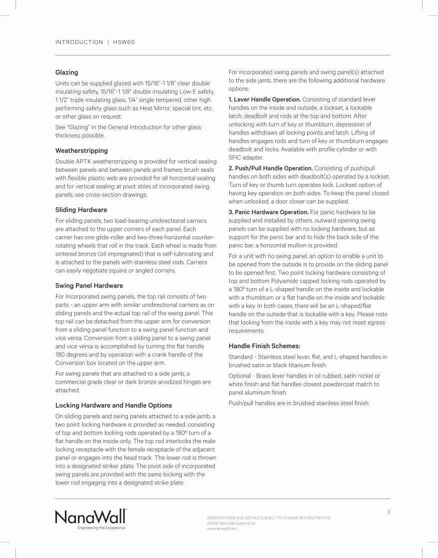
Glazing
Units can be supplied glazed with 15/16”-1 1/8” clear double insulating safety, 15/16”-1 1/8” double insulating Low-E safety, 1 1/2” triple insulating glass, 1/4” single tempered, other high performing safety glass such as Heat Mirror, special tint, etc. or other glass on request.
See “Glazing” in the General Introduction for other glass thickness possible.
Weatherstripping
Double APTK weatherstripping is provided for vertical sealing between panels and between panels and frames; brush seals with flexible plastic web are provided for all horizontal sealing and for vertical sealing at pivot stiles of incorporated swing panels; see cross-section drawings.
Sliding Hardware
For sliding panels, two load-bearing unidirectional carriers are attached to the upper corners of each panel. Each carrier has one glide-roller and two-three horizontal counter-rotating wheels that roll in the track. Each wheel is made from sintered bronze (oil impregnated) that is self-lubricating and is attached to the panels with stainless steel rods. Carriers can easily negotiate square or angled corners.
Swing Panel Hardware
For Incorporated swing panels, the top rail consists of two parts - an upper arm with similar unidirectional carriers as on sliding panels and the actual top rail of the swing panel. This top rail can be detached from the upper arm for conversion from a sliding panel function to a swing panel function and vice versa. Conversion from a sliding panel to a swing panel and vice versa is accomplished by turning the flat handle 180 degrees and by operation with a crank handle of the Conversion box located on the upper arm.
For swing panels that are attached to a side jamb, a commercial grade clear or dark bronze anodized hinges are attached.
Locking Hardware and Handle Options
On sliding panels and swing panels attached to a side jamb, a two point locking hardware is provided as needed, consisting of top and bottom locking rods operated by a 180º turn of a flat handle on the inside only. The top rod interlocks the male locking receptacle with the female receptacle of the adjacent panel or engages into the head track. The lower rod is thrown into a designated striker plate. The pivot side of incorporated swing panels are provided with the same locking with the lower rod engaging into a designated strike plate.
For incorporated swing panels and swing panel(s) attached to the side jamb, there are the following additional hardware options:
1. Lever Handle Operation. Consisting of standard lever handles on the inside and outside, a lockset, a lockable latch, deadbolt and rods at the top and bottom. After unlocking with turn of key or thumbturn, depression of handles withdraws all locking points and latch. Lifting of handles engages rods and turn of key or thumbturn engages deadbolt and locks. Available with profile cylinder or with SFIC adapter.
2. Push/Pull Handle Operation. Consisting of push/pull handles on both sides with deadbolt(s) operated by a lockset. Turn of key or thumb turn operates lock. Lockset option of having key operation on both sides. To keep the panel closed when unlocked, a door closer can be supplied.
3. Panic Hardware Operation. For panic hardware to be supplied and installed by others, outward opening swing panels can be supplied with no locking hardware, but as support for the panic bar and to hide the back side of the panic bar, a horizontal mullion is provided.
For a unit with no swing panel, an option to enable a unit to be opened from the outside is to provide on the sliding panel to be opened first: Two point locking hardware consisting of top and bottom Polyamide capped locking rods operated by a 180º turn of a L-shaped handle on the inside and lockable with a thumbturn or a flat handle on the inside and lockable with a key. In both cases, there will be an L-shaped/flat handle on the outside that is lockable with a key. Please note that locking from the inside with a key may not meet egress requirements.
Handle Finish Schemes:
Standard - Stainless steel lever, flat, and L-shaped handles in brushed satin or black titanium finish.
Optional - Brass lever handles in oil rubbed, satin nickel or white finish and flat handles closest powdercoat match to panel aluminum finish.
Push/pull handles are in brushed stainless steel finish.
INTRODUCTION | HSW60
4
ENGINEERING DETAILS | HSW60
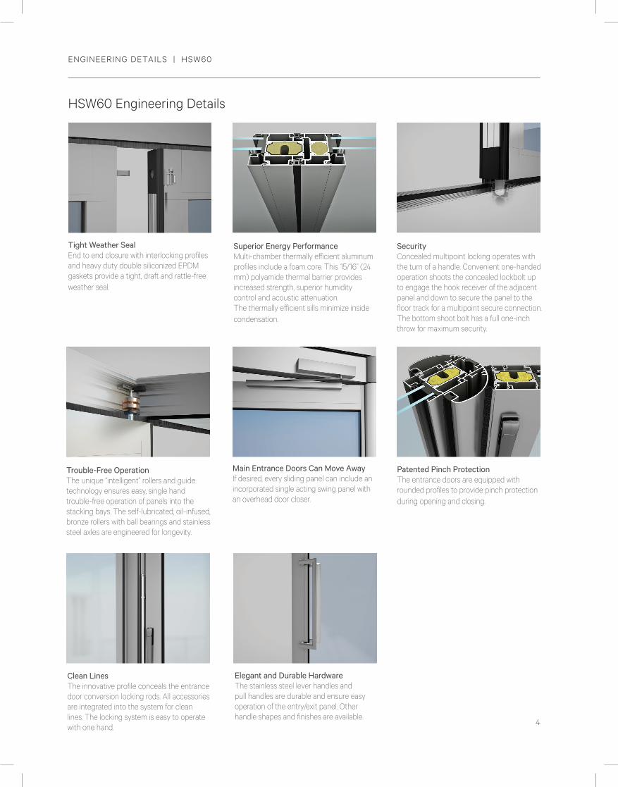
SecurityConcealed multipoint locking operates with the turn of a handle. Convenient one-handed operation shoots the concealed lockbolt up to engage the hook receiver of the adjacent panel and down to secure the panel to the floor track for a multipoint secure connection. The bottom shoot bolt has a full one-inch throw for maximum security.
Trouble-Free OperationThe unique “intelligent” rollers and guide technology ensures easy, single hand trouble-free operation of panels into the stacking bays. The self-lubricated, oil-infused, bronze rollers with ball bearings and stainless steel axles are engineered for longevity.
Superior Energy PerformanceMulti-chamber thermally efficient aluminum profiles include a foam core. This 15/16” (24 mm) polyamide thermal barrier provides increased strength, superior humidity control and acoustic attenuation. The thermally efficient sills minimize inside condensation.
Main Entrance Doors Can Move AwayIf desired, every sliding panel can include an incorporated single acting swing panel with an overhead door closer.
Patented Pinch ProtectionThe entrance doors are equipped with rounded profiles to provide pinch protection during opening and closing.
Elegant and Durable HardwareThe stainless steel lever handles and pull handles are durable and ensure easy operation of the entry/exit panel. Other handle shapes and finishes are available.
Tight Weather SealEnd to end closure with interlocking profiles and heavy duty double siliconized EPDM gaskets provide a tight, draft and rattle-free weather seal.
Clean LinesThe innovative profile conceals the entrance door conversion locking rods. All accessories are integrated into the system for clean lines. The locking system is easy to operate with one hand.
HSW60 Engineering Details

5
TESTING RESULTS | HSW60
HSW60
TYPE OF TEST RESULTS
Air Infiltration qASTM E-283, cfm/ft2
@ 1.6 psf (75 Pa): 0.30 (1.5 L/s/m2)
A2 w
Water Penetration qASTM E-547 and ASTM E-331
(with low profile saddle sill)
#1Unit with weepholes from middle channel:
No uncontrolled water entry
@ 2.92 psf (140 Pa)
subject to the following adaptationsof the sill in the field by others:
1. Remove the gasket covering the middle channel
2. Drill weep holes through the outer bottom wall in middle channel (1” x 1/4” weep hole per panel)
3. Drill weep holes through the lower front face of sill (1” x 1/4” weep hole per panel)
#2Unit with weepholes from inner channel:
No uncontrolled water entry
@ 6 psf (290 Pa)
subject to the following adaptationsof the sill in the field by others:
1. Remove the gaskets covering the inner channel.
2. Drill weep holes through the bottom of this channel (about one 1” x 1/4” weep hole per panel.)
3. Drill weep holes through the lower front face of the sill to the inner channel bottom (about 1” x 1/4” weep hole per panel.)
Please note that due to varying site requirements and conditions, these sills will not be prepared for drainage by NanaWall Systems, Inc. If this drainage system is desired, we recommend that a qualified professional construct this system on the project site that is strictly in accordance with instructions provided by NanaWall Systems, Inc. and in accordance with good waterproofing techniques. If drain connections are not made, or are not possible, unit may leak with wind driven rain.
Structural Load DeflectionASTM E-330: pass
See Design Windload Charts forother sized panels
Note that the structural test pressures were50% higher than the design pressures.
DESIGN PRESSURE
Positive
@ 45 psf
(2160 Pa)
Negative
@ 45 psf
(2160 Pa)
For saddle sill, class SP-PG40 (weep holes by others),panel size - 3’ 1” x 9’ 5” (940 mm x 2870 mm) w
Forced Entry Resistance qASTM F842
Type A. Grade: 40 Pass
Life Cycle PerformanceAAMA 920
For incorporated swing panel 500,000 cycles - pass
Acoustical Performance e
Stc 45 special laminated glass achieved Stc and Rw values of 43 with head track recessedand 41 with head track exposed and with Stc 32 insulated glass achieved Stc of 32
with headtrack recessed or exposed.
q Excerpts of results of a 6 panel unit tested by Architectural Testing, Inc., an independent testing laboratory, in October 2010per AA MA/WD MA/CSA 101/I.S.2/A440 Fenestration Standard. Unit was 18’0 1/2” W x 10’ H with a total of 6 panels consisting of a half swingpanel attached to the side jamb, 3 sliding panels and 2 incorporated swing panels. All locking was standard and sill was low profile saddle sill.
w For Canada, tested to NAFS-08 or equivalent and CSA A44051-09.
e Excerpts of results of 13’7” W x 8’8” H 4 panel unit with swing panel attached to the side jamb tested by Nusing Mobile Trennwandtechnile, Munster, Germany, an independent testing laboratory in december 2011.
The HSW60 is being re-simulated in 2015 with the latest glass options on units with 1 lite and 2 lites with horizontal mullion.Check www.NanaWall. com for the latest updates.
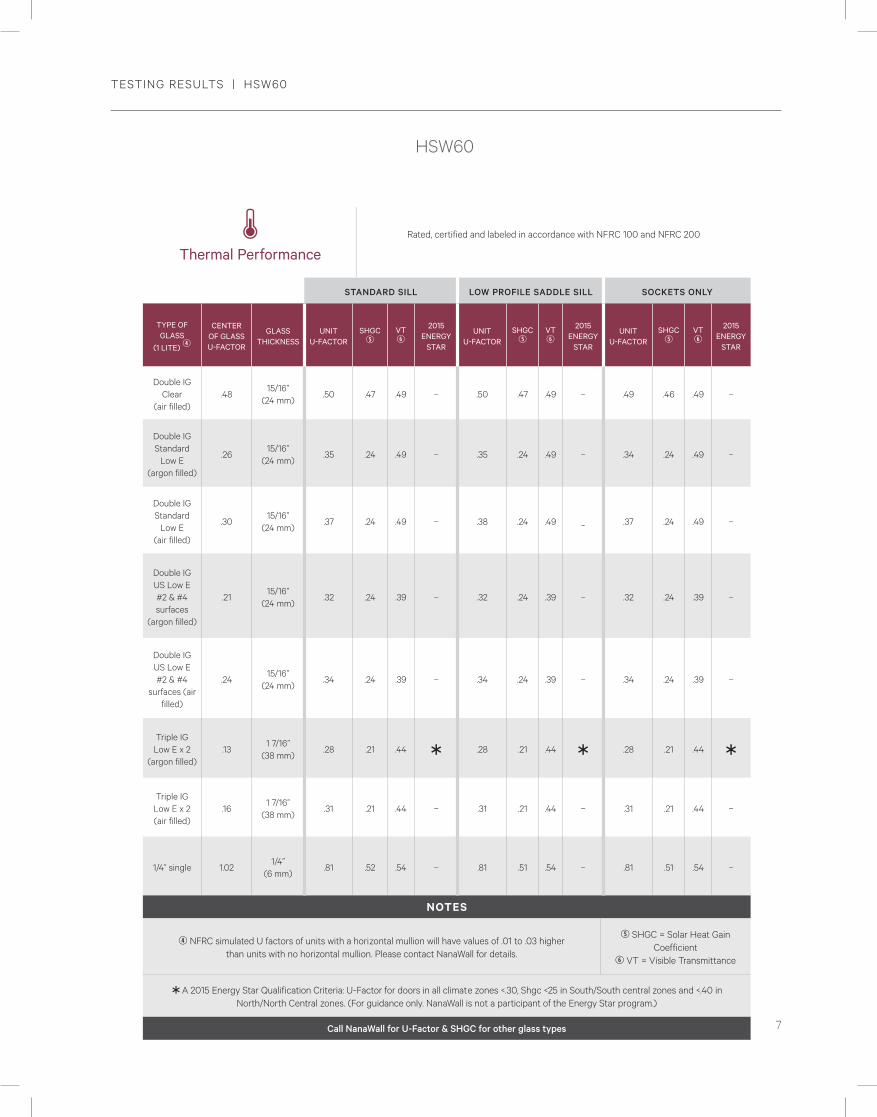
Thermal PerformanceRated, certified and labeled in accordance with NFRC 100 and NFRC 200
STANDARD SILL LOW PROFILE SADDLE SILL SOCKETS ONLY
TYPE OFGLASS
(1 LITE) r
CENTER OF GLASS U-FACTOR
GLASS THICKNESS
UNIT U-FACTOR
SHGC t
VT y
2015 ENERGY
STAR
UNIT U-FACTOR
SHGC t
VT y
2015 ENERGY
STAR
UNIT U-FACTOR
SHGC t
VT y
2015 ENERGY
STAR
Double IG Clear
(air filled).48
15/16”(24 mm)
.50 .47 .49 – .50 .47 .49 – .49 .46 .49 –
Double IG Standard
Low E (argon filled)
.2615/16”
(24 mm).35 .24 .49 – .35 .24 .49 – .34 .24 .49 –
Double IG Standard
Low E(air filled)
.3015/16”
(24 mm).37 .24 .49 – .38 .24 .49 _ .37 .24 .49 –
Double IG US Low E #2 & #4 surfaces
(argon filled)
.2115/16”
(24 mm).32 .24 .39 – .32 .24 .39 – .32 .24 .39 –
Double IG US Low E #2 & #4
surfaces (air filled)
.2415/16”
(24 mm).34 .24 .39 – .34 .24 .39 – .34 .24 .39 –
Triple IG Low E x 2
(argon filled).13
1 7/16”(38 mm)
.28 .21 .44 Ü .28 .21 .44 Ü .28 .21 .44 Ü
Triple IG Low E x 2(air filled)
.161 7/16”
(38 mm).31 .21 .44 – .31 .21 .44 – .31 .21 .44 –
1/4” single 1.021/4”
(6 mm).81 .52 .54 – .81 .51 .54 – .81 .51 .54 –
NOTES
r NFRC simulated U factors of units with a horizontal mullion will have values of .01 to .03 higherthan units with no horizontal mullion. Please contact NanaWall for details.
t SHGC = Solar Heat Gain Coefficient
y VT = Visible Transmittance
ÜA 2015 Energy Star Qualification Criteria: U-Factor for doors in all climate zones <.30, Shgc <25 in South/South central zones and <.40 in North/North Central zones. (For guidance only. NanaWall is not a participant of the Energy Star program.)
Call NanaWall for U-Factor & SHGC for other glass types

SPECIFICATIONS AND DETAILS SUBJECT TO CHANGE WITHOUT NOTICE©2016 Nana Wall Systems, Inc.www.nanawall.com
6
TESTING RESULTS | HSW60
HSW60
TYPE OF TEST RESULTS
Air Infiltration qASTM E-283, cfm/ft2
@ 1.6 psf (75 Pa): 0.30 (1.5 L/s/m2)
A2 w
Water Penetration qASTM E-547 and ASTM E-331
(with low profile saddle sill)
#1Unit with weepholes from middle channel:
No uncontrolled water entry
@ 2.92 psf (140 Pa)
subject to the following adaptationsof the sill in the field by others:
1. Remove the gasket covering the middle channel
2. Drill weep holes through the outer bottom wall in middle channel (1” x 1/4” weep hole per panel)
3. Drill weep holes through the lower front face of sill (1” x 1/4” weep hole per panel)
#2Unit with weepholes from inner channel:
No uncontrolled water entry
@ 6 psf (290 Pa)
subject to the following adaptationsof the sill in the field by others:
1. Remove the gaskets covering the inner channel.
2. Drill weep holes through the bottom of this channel (about one 1” x 1/4” weep hole per panel.)
3. Drill weep holes through the lower front face of the sill to the inner channel bottom (about 1” x 1/4” weep hole per panel.)
Please note that due to varying site requirements and conditions, these sills will not be prepared for drainage by NanaWall Systems, Inc. If this drainage system is desired, we recommend that a qualified professional construct this system on the project site that is strictly in accordance with instructions provided by NanaWall Systems, Inc. and in accordance with good waterproofing techniques. If drain connections are not made, or are not possible, unit may leak with wind driven rain.
Structural Load DeflectionASTM E-330: pass
See Design Windload Charts forother sized panels
Note that the structural test pressures were50% higher than the design pressures.
DESIGN PRESSURE
Positive
@ 45 psf
(2160 Pa)
Negative
@ 45 psf
(2160 Pa)
For saddle sill, class SP-PG40 (weep holes by others),panel size - 3’ 1” x 9’ 5” (940 mm x 2870 mm) w
Forced Entry Resistance qASTM F842
Type A. Grade: 40 Pass
Life Cycle PerformanceAAMA 920
For incorporated swing panel 500,000 cycles - pass
Acoustical Performance e
Stc 45 special laminated glass achieved Stc and Rw values of 43 with head track recessedand 41 with head track exposed and with Stc 32 insulated glass achieved Stc of 32
with headtrack recessed or exposed.
q Excerpts of results of a 6 panel unit tested by Architectural Testing, Inc., an independent testing laboratory, in October 2010per AA MA/WD MA/CSA 101/I.S.2/A440 Fenestration Standard. Unit was 18’0 1/2” W x 10’ H with a total of 6 panels consisting of a half swingpanel attached to the side jamb, 3 sliding panels and 2 incorporated swing panels. All locking was standard and sill was low profile saddle sill.
w For Canada, tested to NAFS-08 or equivalent and CSA A44051-09.
e Excerpts of results of 13’7” W x 8’8” H 4 panel unit with swing panel attached to the side jamb tested by Nusing Mobile Trennwandtechnile, Munster, Germany, an independent testing laboratory in december 2011.
The HSW60 is being re-simulated in 2015 with the latest glass options on units with 1 lite and 2 lites with horizontal mullion.Check www.NanaWall. com for the latest updates.
Thermal PerformanceRated, certified and labeled in accordance with NFRC 100 and NFRC 200
STANDARD SILL LOW PROFILE SADDLE SILL SOCKETS ONLY
TYPE OFGLASS
(1 LITE) r
CENTER OF GLASS U-FACTOR
GLASS THICKNESS
UNIT U-FACTOR
SHGC t
VT y
2015 ENERGY
STAR
UNIT U-FACTOR
SHGC t
VT y
2015 ENERGY
STAR
UNIT U-FACTOR
SHGC t
VT y
2015 ENERGY
STAR
Double IG Clear
(air filled).48
15/16”(24 mm)
.50 .47 .49 – .50 .47 .49 – .49 .46 .49 –
Double IG Standard
Low E (argon filled)
.2615/16”
(24 mm).35 .24 .49 – .35 .24 .49 – .34 .24 .49 –
Double IG Standard
Low E(air filled)
.3015/16”
(24 mm).37 .24 .49 – .38 .24 .49 _ .37 .24 .49 –
Double IG US Low E #2 & #4 surfaces
(argon filled)
.2115/16”
(24 mm).32 .24 .39 – .32 .24 .39 – .32 .24 .39 –
Double IG US Low E #2 & #4
surfaces (air filled)
.2415/16”
(24 mm).34 .24 .39 – .34 .24 .39 – .34 .24 .39 –
Triple IG Low E x 2
(argon filled).13
1 7/16”(38 mm)
.28 .21 .44 Ü .28 .21 .44 Ü .28 .21 .44 Ü
Triple IG Low E x 2(air filled)
.161 7/16”
(38 mm).31 .21 .44 – .31 .21 .44 – .31 .21 .44 –
1/4” single 1.021/4”
(6 mm).81 .52 .54 – .81 .51 .54 – .81 .51 .54 –
NOTES
r NFRC simulated U factors of units with a horizontal mullion will have values of .01 to .03 higherthan units with no horizontal mullion. Please contact NanaWall for details.
t SHGC = Solar Heat Gain Coefficient
y VT = Visible Transmittance
ÜA 2015 Energy Star Qualification Criteria: U-Factor for doors in all climate zones <.30, Shgc <25 in South/South central zones and <.40 in North/North Central zones. (For guidance only. NanaWall is not a participant of the Energy Star program.)
Call NanaWall for U-Factor & SHGC for other glass types
HSW60
7
TESTING RESULTS | HSW60
HSW60
TYPE OF TEST RESULTS
Air Infiltration qASTM E-283, cfm/ft2
@ 1.6 psf (75 Pa): 0.30 (1.5 L/s/m2)
A2 w
Water Penetration qASTM E-547 and ASTM E-331
(with low profile saddle sill)
#1Unit with weepholes from middle channel:
No uncontrolled water entry
@ 2.92 psf (140 Pa)
subject to the following adaptationsof the sill in the field by others:
1. Remove the gasket covering the middle channel
2. Drill weep holes through the outer bottom wall in middle channel (1” x 1/4” weep hole per panel)
3. Drill weep holes through the lower front face of sill (1” x 1/4” weep hole per panel)
#2Unit with weepholes from inner channel:
No uncontrolled water entry
@ 6 psf (290 Pa)
subject to the following adaptationsof the sill in the field by others:
1. Remove the gaskets covering the inner channel.
2. Drill weep holes through the bottom of this channel (about one 1” x 1/4” weep hole per panel.)
3. Drill weep holes through the lower front face of the sill to the inner channel bottom (about 1” x 1/4” weep hole per panel.)
Please note that due to varying site requirements and conditions, these sills will not be prepared for drainage by NanaWall Systems, Inc. If this drainage system is desired, we recommend that a qualified professional construct this system on the project site that is strictly in accordance with instructions provided by NanaWall Systems, Inc. and in accordance with good waterproofing techniques. If drain connections are not made, or are not possible, unit may leak with wind driven rain.
Structural Load DeflectionASTM E-330: pass
See Design Windload Charts forother sized panels
Note that the structural test pressures were50% higher than the design pressures.
DESIGN PRESSURE
Positive
@ 45 psf
(2160 Pa)
Negative
@ 45 psf
(2160 Pa)
For saddle sill, class SP-PG40 (weep holes by others),panel size - 3’ 1” x 9’ 5” (940 mm x 2870 mm) w
Forced Entry Resistance qASTM F842
Type A. Grade: 40 Pass
Life Cycle PerformanceAAMA 920
For incorporated swing panel 500,000 cycles - pass
Acoustical Performance e
Stc 45 special laminated glass achieved Stc and Rw values of 43 with head track recessedand 41 with head track exposed and with Stc 32 insulated glass achieved Stc of 32
with headtrack recessed or exposed.
q Excerpts of results of a 6 panel unit tested by Architectural Testing, Inc., an independent testing laboratory, in October 2010per AA MA/WD MA/CSA 101/I.S.2/A440 Fenestration Standard. Unit was 18’0 1/2” W x 10’ H with a total of 6 panels consisting of a half swingpanel attached to the side jamb, 3 sliding panels and 2 incorporated swing panels. All locking was standard and sill was low profile saddle sill.
w For Canada, tested to NAFS-08 or equivalent and CSA A44051-09.
e Excerpts of results of 13’7” W x 8’8” H 4 panel unit with swing panel attached to the side jamb tested by Nusing Mobile Trennwandtechnile, Munster, Germany, an independent testing laboratory in december 2011.
The HSW60 is being re-simulated in 2015 with the latest glass options on units with 1 lite and 2 lites with horizontal mullion.Check www.NanaWall. com for the latest updates.
Thermal PerformanceRated, certified and labeled in accordance with NFRC 100 and NFRC 200
STANDARD SILL LOW PROFILE SADDLE SILL SOCKETS ONLY
TYPE OFGLASS
(1 LITE) r
CENTER OF GLASS U-FACTOR
GLASS THICKNESS
UNIT U-FACTOR
SHGC t
VT y
2015 ENERGY
STAR
UNIT U-FACTOR
SHGC t
VT y
2015 ENERGY
STAR
UNIT U-FACTOR
SHGC t
VT y
2015 ENERGY
STAR
Double IG Clear
(air filled).48
15/16”(24 mm)
.50 .47 .49 – .50 .47 .49 – .49 .46 .49 –
Double IG Standard
Low E (argon filled)
.2615/16”
(24 mm).35 .24 .49 – .35 .24 .49 – .34 .24 .49 –
Double IG Standard
Low E(air filled)
.3015/16”
(24 mm).37 .24 .49 – .38 .24 .49 _ .37 .24 .49 –
Double IG US Low E #2 & #4 surfaces
(argon filled)
.2115/16”
(24 mm).32 .24 .39 – .32 .24 .39 – .32 .24 .39 –
Double IG US Low E #2 & #4
surfaces (air filled)
.2415/16”
(24 mm).34 .24 .39 – .34 .24 .39 – .34 .24 .39 –
Triple IG Low E x 2
(argon filled).13
1 7/16”(38 mm)
.28 .21 .44 Ü .28 .21 .44 Ü .28 .21 .44 Ü
Triple IG Low E x 2(air filled)
.161 7/16”
(38 mm).31 .21 .44 – .31 .21 .44 – .31 .21 .44 –
1/4” single 1.021/4”
(6 mm).81 .52 .54 – .81 .51 .54 – .81 .51 .54 –
NOTES
r NFRC simulated U factors of units with a horizontal mullion will have values of .01 to .03 higherthan units with no horizontal mullion. Please contact NanaWall for details.
t SHGC = Solar Heat Gain Coefficient
y VT = Visible Transmittance
ÜA 2015 Energy Star Qualification Criteria: U-Factor for doors in all climate zones <.30, Shgc <25 in South/South central zones and <.40 in North/North Central zones. (For guidance only. NanaWall is not a participant of the Energy Star program.)
Call NanaWall for U-Factor & SHGC for other glass types
HSW60
SPECIFICATIONS AND DETAILS SUBJECT TO CHANGE WITHOUT NOTICE©2016 Nana Wall Systems, Inc.www.nanawall.com
8
MAXIMUM SIZE CHART | HSW60 (with different number of panels)
FR
AM
E H
EIG
HT
OF
UN
IT
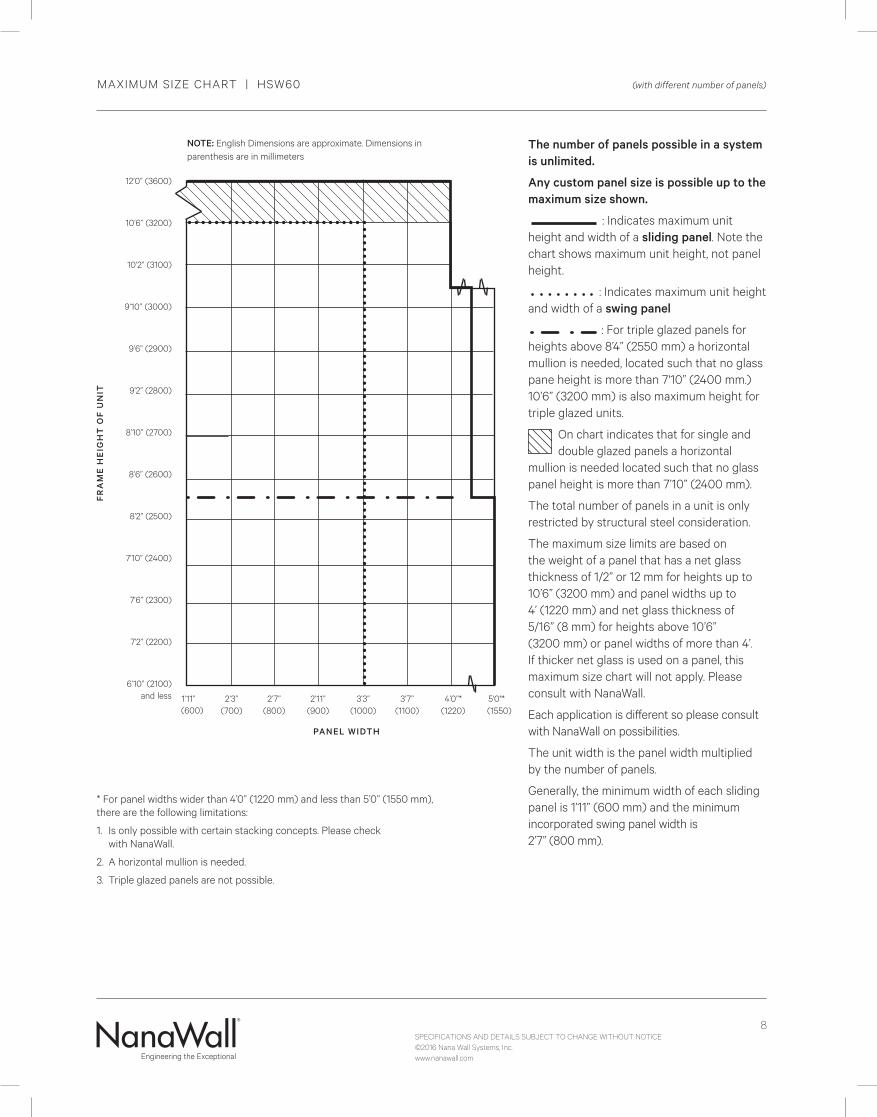
The number of panels possible in a system is unlimited.
Any custom panel size is possible up to the maximum size shown.
: Indicates maximum unit height and width of a sliding panel. Note the chart shows maximum unit height, not panel height.
: Indicates maximum unit height and width of a swing panel
: For triple glazed panels for heights above 8’4” (2550 mm) a horizontal mullion is needed, located such that no glass pane height is more than 7'10” (2400 mm.) 10’6” (3200 mm) is also maximum height for triple glazed units.
On chart indicates that for single and double glazed panels a horizontal
mullion is needed located such that no glass panel height is more than 7’10” (2400 mm).
The total number of panels in a unit is only restricted by structural steel consideration.
The maximum size limits are based on the weight of a panel that has a net glass thickness of 1/2” or 12 mm for heights up to 10’6” (3200 mm) and panel widths up to 4’ (1220 mm) and net glass thickness of 5/16” (8 mm) for heights above 10’6” (3200 mm) or panel widths of more than 4’. If thicker net glass is used on a panel, this maximum size chart will not apply. Please consult with NanaWall.
Each application is different so please consult with NanaWall on possibilities.
The unit width is the panel width multiplied by the number of panels.
Generally, the minimum width of each sliding panel is 1’11” (600 mm) and the minimum incorporated swing panel width is 2’7” (800 mm).
12’0” (3600)
10’6” (3200)
10’2” (3100)
9’10” (3000)
9’6” (2900)
9’2” (2800)
8’10” (2700)
8’6” (2600)
8’2” (2500)
7’10” (2400)
7’6” (2300)
7’2” (2200)
6’10” (2100) and less 2’3” 2’7” 2’11” 3’3” 3’7” 4’0”* 5'0"*
(700) (800) (900) (1000) (1100) (1220) (1550)
* For panel widths wider than 4’0” (1220 mm) and less than 5’0” (1550 mm), there are the following limitations:
1. Is only possible with certain stacking concepts. Please check with NanaWall.
2. A horizontal mullion is needed.
3. Triple glazed panels are not possible.
PANEL WIDTH
1’11” (600)
NOTE: English Dimensions are approximate. Dimensions in parenthesis are in millimeters
SPECIFICATIONS AND DETAILS SUBJECT TO CHANGE WITHOUT NOTICE©2016 Nana Wall Systems, Inc.www.nanawall.com
9
POSSIBLE STACKING AND CONFIGURATIONS | HSW60
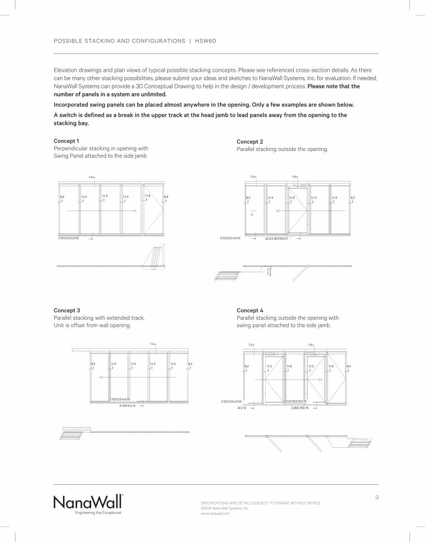
Concept 1 Perpendicular stacking in opening with Swing Panel attached to the side jamb
Concept 2 Parallel stacking outside the opening.
Concept 3 Parallel stacking with extended track. Unit is offset from wall opening.
Elevation drawings and plan views of typical possible stacking concepts. Please see referenced cross-section details. As there can be many other stacking possibilities, please submit your ideas and sketches to NanaWall Systems, Inc. for evaluation. If needed, NanaWall Systems can provide a 3D Conceptual Drawing to help in the design / development process. Please note that the number of panels in a system are unlimited.
Incorporated swing panels can be placed almost anywhere in the opening. Only a few examples are shown below.
A switch is defined as a break in the upper track at the head jamb to lead panels away from the opening to the stacking bay.
Concept 4 Parallel stacking outside the opening with swing panel attached to the side jamb.
2.12/2.2/2.4/2.02 2.12/2.2/2.4/2.02
2.12/2.2/2.4/2.022.12/2.2/2.4/2.02
22.0/2.18/2.16/2.13
22.0/2.18/2.16/2.13

SPECIFICATIONS AND DETAILS SUBJECT TO CHANGE WITHOUT NOTICE©2016 Nana Wall Systems, Inc.www.nanawall.com
10
POSSIBLE STACKING AND CONFIGURATIONS | HSW60
Concept 8 In tandem stacking of panels along adjacent wall.
Concept 9 Stacking outside the opening at an angle.
Concept 5 Angled stacking outside the opening.
Concept 6 Perpendicular stacking outside the opening.
Concept 10 Parallel stacking within the opening with swing panel attached to the side jamb.
2.12/2.2/2.4/2.022.12/2.2/2.4/2.02
2.12/2.2/2.4/2.02
2.12/2.2/2.4/2.02
22.0/2.18/2.16/2.13
SPECIFICATIONS AND DETAILS SUBJECT TO CHANGE WITHOUT NOTICE©2016 Nana Wall Systems, Inc.www.nanawall.com
11
POSSIBLE STACKING AND CONFIGURATIONS | HSW60
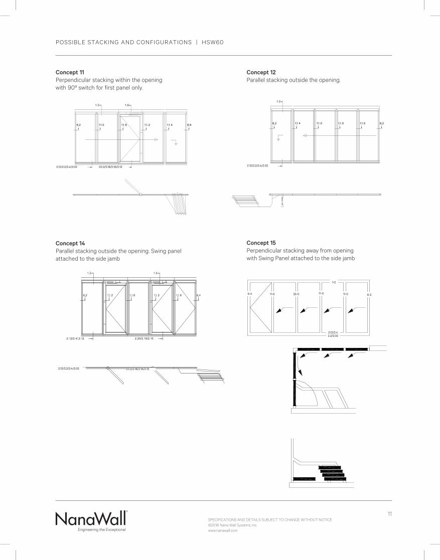
Concept 11 Perpendicular stacking within the opening with 90º switch for first panel only.
Concept 14 Parallel stacking outside the opening. Swing panel attached to the side jamb
Concept 15 Perpendicular stacking away from opening with Swing Panel attached to the side jamb
11-66-4
1-2
35-0 11-0 11-0 6-2
2.12/2.4 2.2/2.02
MIN
: VAR
IES
Concept 12 Parallel stacking outside the opening.
2.12/2.2/2.4/2.02 2.12/2.2/2.4/2.02
2.12/2.2/2.4/2.02
22.0/2.18/2.16/2.13
22.0/2.18/2.16/2.13
SPECIFICATIONS AND DETAILS SUBJECT TO CHANGE WITHOUT NOTICE©2016 Nana Wall Systems, Inc.www.nanawall.com
12
POSSIBLE STACKING AND CONFIGURATIONS | HSW60
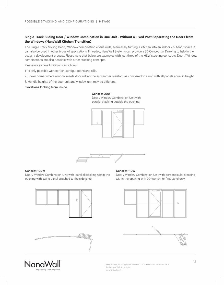
Concept 10DW Door / Window Combination Unit with parallel stacking within the opening with swing panel attached to the side jamb.
Concept 11DW Door / Window Combination Unit with perpendicular stacking within the opening with 90º switch for first panel only.
Concept 2DW Door / Window Combination Unit with parallel stacking outside the opening.
Single Track Sliding Door / Window Combination in One Unit - Without a Fixed Post Separating the Doors from the Windows (NanaWall Kitchen Transition)The Single Track Sliding Door / Window combination opens wide, seamlessly turning a kitchen into an indoor / outdoor space. It can also be used in other types of applications. If needed, NanaWall Systems can provide a 3D Conceptual Drawing to help in the design / development process. Please note that below are examples with just three of the HSW stacking concepts. Door / Window combinations are also possible with other stacking concepts.
Please note some limitations as follows:
1. Is only possible with certain configurations and sills.
2. Lower corner where window meets door will not be as weather resistant as compared to a unit with all panels equal in height.
3. Handle heights of the door unit and window unit may be different.
Elevations looking from Inside.
13
VERTICAL SECTIONS FOR SLIDING PANEL OR SWING PANEL ATTACHED TO A SIDE JAMB | HSW60Fr
ame
Hei
ght
FFH
EXTERIOR INTERIOR
FFH
FFH
All Cross Sectional Views Are Half Size
EXTERIOR INTERIOR
EXTERIOR INTERIOR
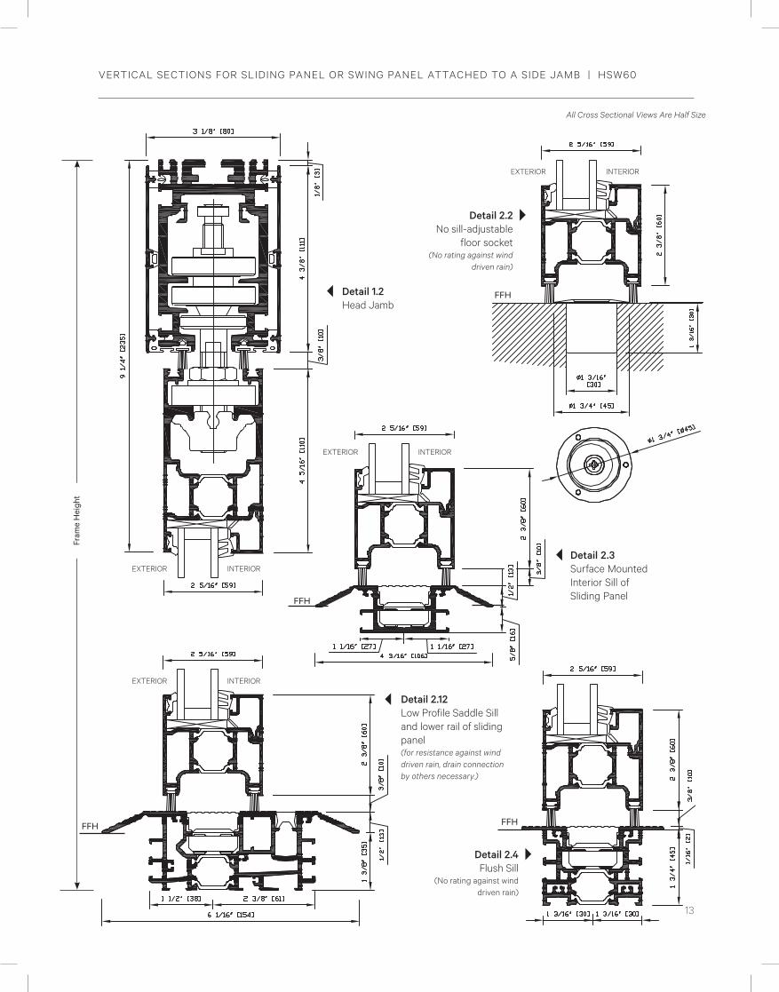
Detail 2.2 No sill-adjustable
floor socket (No rating against wind
driven rain)
Detail 2.4 Flush Sill
(No rating against wind driven rain)
Detail 2.12 Low Profile Saddle Sill and lower rail of sliding panel (for resistance against wind driven rain, drain connection by others necessary.)
Detail 1.2 Head Jamb
Detail 2.3 Surface Mounted Interior Sill of Sliding PanelFFH
EXTERIOR INTERIOR

SPECIFICATIONS AND DETAILS SUBJECT TO CHANGE WITHOUT NOTICE©2016 Nana Wall Systems, Inc.www.nanawall.com
14
Detail 1.6 Head Jamb of Incorporated Swing Panel
VERTICAL SECTIONS FOR SLIDING PANEL WITH INCORPORATED SWING PANEL | HSW60
EXTERIOR INTERIOR
Maximum gap to be 3/8" (10 mm)
ADJACENT WALLDetail 2.18 Flush Sill (No rating against wind driven rain)
INTERIOR
EXTERIOR
SPECIFICATIONS AND DETAILS SUBJECT TO CHANGE WITHOUT NOTICE©2016 Nana Wall Systems, Inc.www.nanawall.com
15
VERTICAL AND HORIZONTAL SECTIONS | HSW60 All Cross Sectional Views Are Half Size
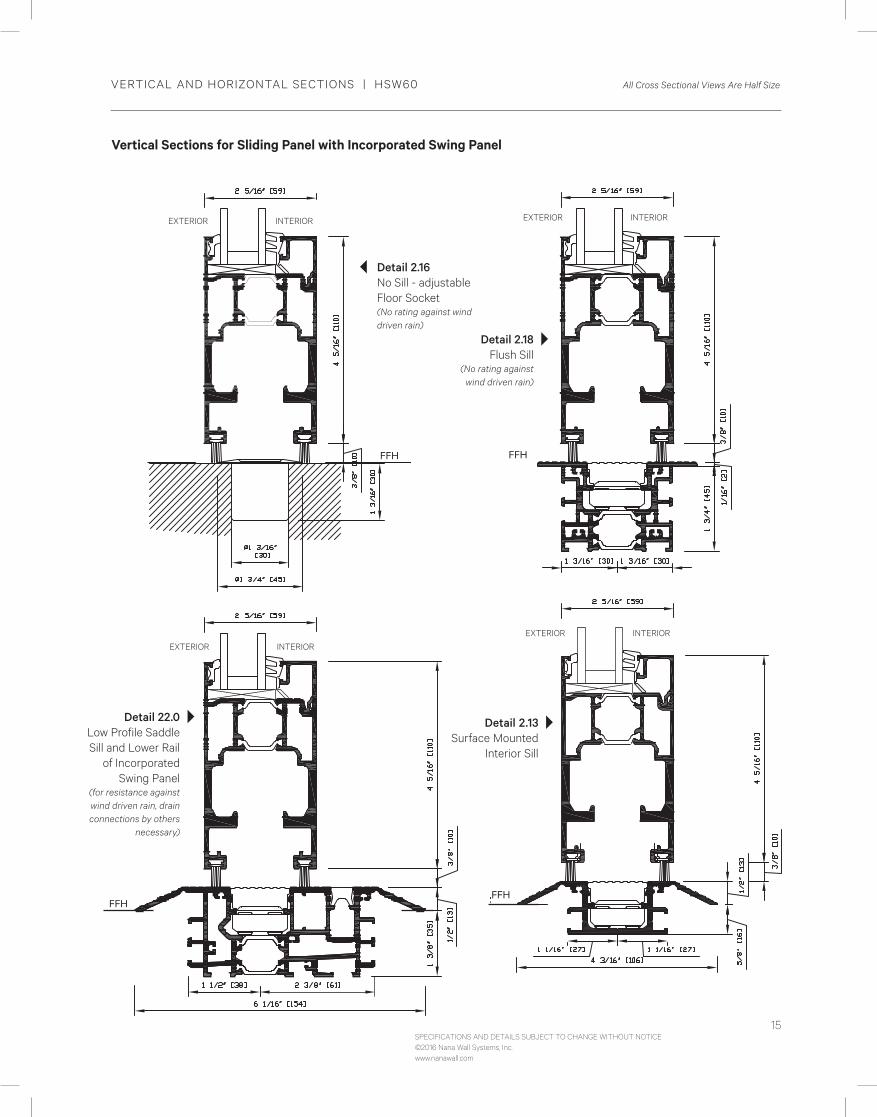
Vertical Sections for Sliding Panel with Incorporated Swing Panel
FFH
EXTERIOR INTERIOR
Detail 22.0 Low Profile Saddle Sill and Lower Rail
of Incorporated Swing Panel
(for resistance against wind driven rain, drain connections by others
necessary)
FFH
EXTERIOR INTERIOR
Detail 2.13Surface Mounted
Interior Sill
FFH
EXTERIOR INTERIOR
Detail 2.18 Flush Sill
(No rating against wind driven rain)
Detail 2.16 No Sill - adjustable Floor Socket (No rating against wind driven rain)
FFH
EXTERIOR INTERIOR

SPECIFICATIONS AND DETAILS SUBJECT TO CHANGE WITHOUT NOTICE©2016 Nana Wall Systems, Inc.www.nanawall.com
16
HORIZONTAL SECTIONS | HSW60 All Cross Sectional Views Are Half Size
3 5/8" [92]
5 3/16" [132]
7/16" [10]
Detail 11.2Sliding Panel meeting with hinged side of incorporated swing panel
Detail 11.� Strike side of swing panel meeting sliding panel or strike sides of a pair of swing panels meeting
Detail 35.0 Two Sliding Panels meet at segmented angle (90° to 180°)
INTERIOR
EXTERIOR
INTERIOR
EXTERIOR
INTERIOR
EXTERIOR
SPECIFICATIONS AND DETAILS SUBJECT TO CHANGE WITHOUT NOTICE©2016 Nana Wall Systems, Inc.www.nanawall.com
17
HORIZONTAL SECTIONS | HSW60 All Cross Sectional Views Are Half Size
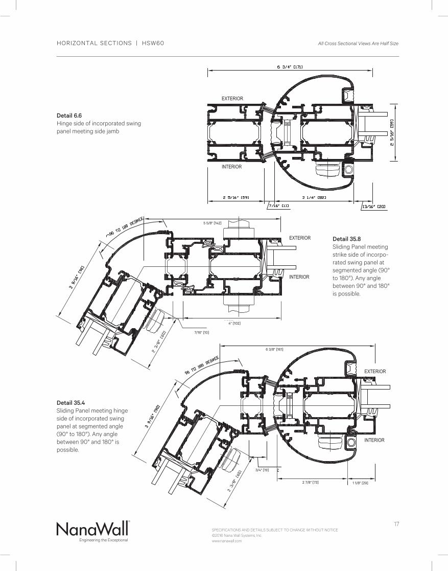
Detail 35.8 Sliding Panel meeting strike side of incorpo-rated swing panel at segmented angle (90° to 180°). Any angle between 90° and 180° is possible.
Detail 35.4 Sliding Panel meeting hinge side of incorporated swing panel at segmented angle (90° to 180°). Any angle between 90° and 180° is possible.
6 3/8" [161]
2 7/8" [73] 1 1/8" [29]
3/4" [19]
Detail 6.6Hinge side of incorporated swing panel meeting side jamb
7/16" [10]
4" [102]
5 5/8" [142]
INTERIOR
EXTERIOR
INTERIOR
EXTERIOR
INTERIOR
EXTERIOR
SPECIFICATIONS AND DETAILS SUBJECT TO CHANGE WITHOUT NOTICE©2016 Nana Wall Systems, Inc.www.nanawall.com
18
HORIZONTAL SECTIONS | HSW60 All Cross Sectional Views Are Half Size
INTERIOR
EXTERIOR
INTERIOR
EXTERIOR
INTERIOR
EXTERIOR
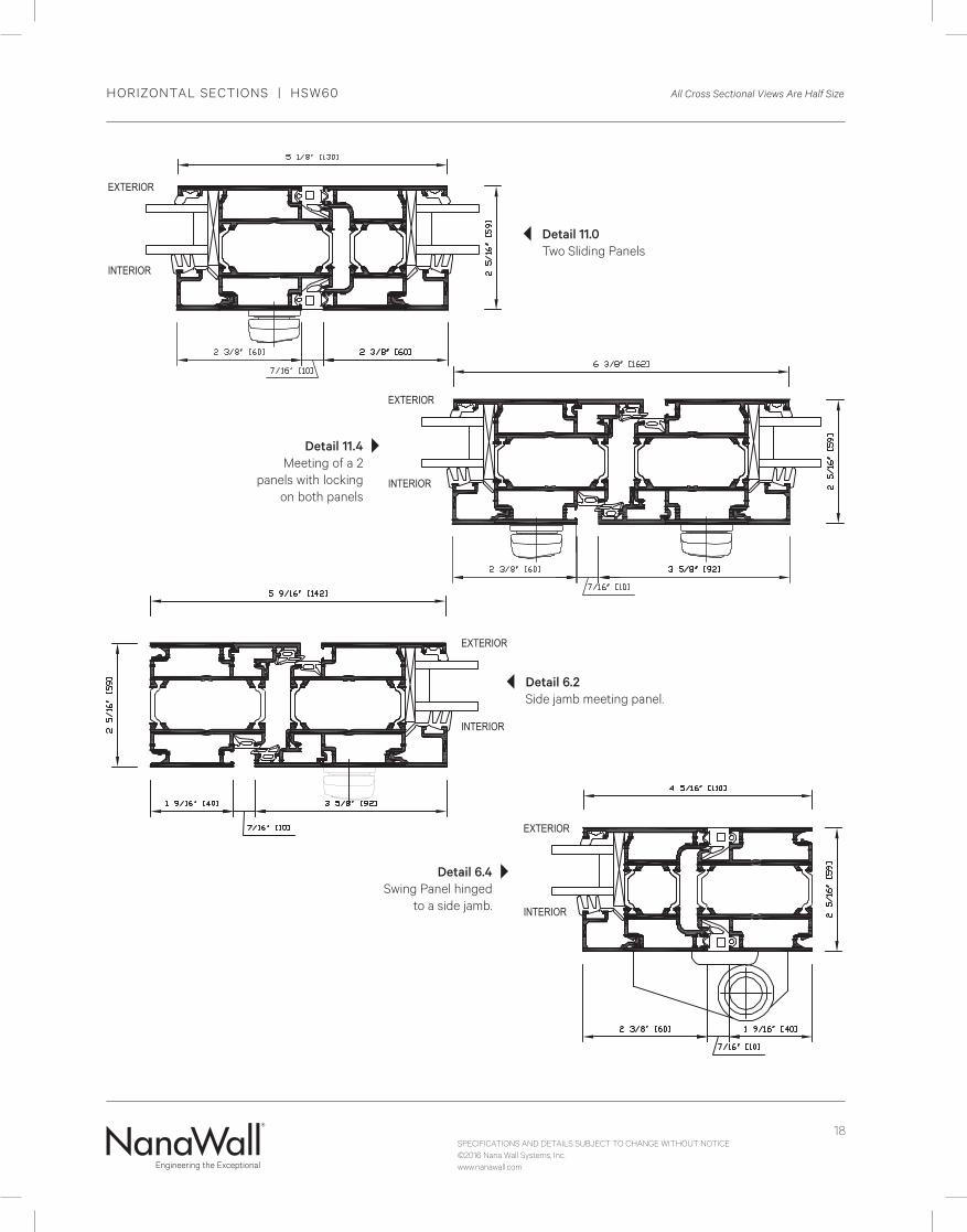
Detail 6.4Swing Panel hinged
to a side jamb.
INTERIOR
EXTERIOR
Detail 11.4 Meeting of a 2
panels with locking on both panels
Detail 11.0Two Sliding Panels
Detail 6.2Side jamb meeting panel.
SPECIFICATIONS AND DETAILS SUBJECT TO CHANGE WITHOUT NOTICE©2016 Nana Wall Systems, Inc.www.nanawall.com
19
SECTION DETAILS | HSW60 All Cross Sectional Views Are Half Size
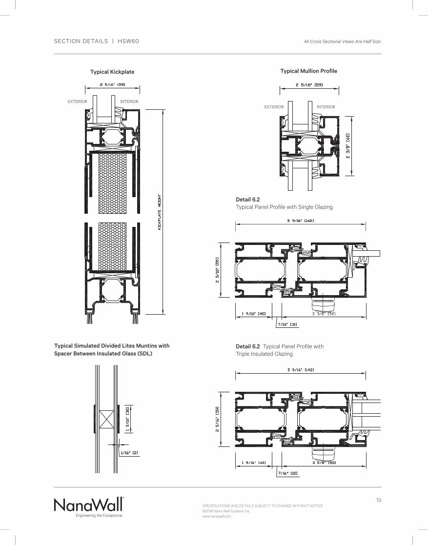
Typical Mullion Profile
Typical Simulated Divided Lites Muntins with Spacer Between Insulated Glass (SDL)
Detail 6.2 Typical Panel Profile with Single Glazing
Detail 6.2 Typical Panel Profile with Triple Insulated Glazing
Typical Kickplate
EXTERIOR INTERIOREXTERIOR INTERIOR
20
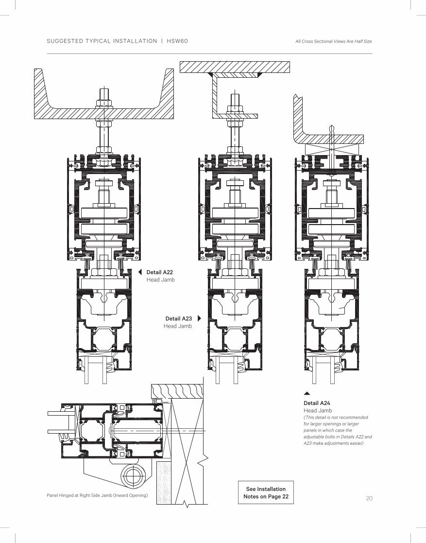
SUGGESTED TYPICAL INSTALLATION | HSW60 All Cross Sectional Views Are Half Size
Panel Hinged at Right Side Jamb (Inward Opening)See Installation
Notes on Page 22
Detail A24 Head Jamb (This detail is not recommended for larger openings or larger panels in which case the adjustable bolts in Details A22 and A23 make adjustments easier)
Detail A22Head Jamb
Detail A23 Head Jamb
SPECIFICATIONS AND DETAILS SUBJECT TO CHANGE WITHOUT NOTICE©2016 Nana Wall Systems, Inc.www.nanawall.com
21
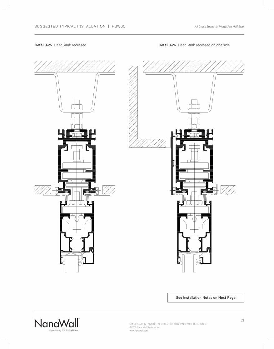
SUGGESTED TYPICAL INSTALLATION | HSW60 All Cross Sectional Views Are Half Size
See Installation Notes on Next Page
Detail A25 Head jamb recessed Detail A26 Head jamb recessed on one side
SPECIFICATIONS AND DETAILS SUBJECT TO CHANGE WITHOUT NOTICE©2016 Nana Wall Systems, Inc.www.nanawall.com
22
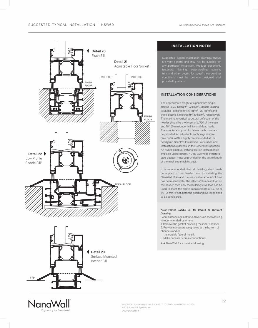
Detail 21 Adjustable Floor Socket
FINISH FLOOR
EXTERIOR INTERIOR
SUGGESTED TYPICAL INSTALLATION | HSW60 All Cross Sectional Views Are Half Size
FFH
INSTALLATION NOTES
Suggested Typical Installation drawings shown are very general and may not be suitable for any particular installation. Product placement, fasteners, flashing, waterproofing, sealant, trim and other details for specific surrounding conditions must be properly designed and provided by others.
INSTALLATION CONSIDERATIONS The approximate weight of a panel with single glazing is 4.5 lbs/sq ft2 (22 kg/m2), double-glazing is 5.5 lbs - 8 lbs/sq ft² (27 kg/m2 - 39 kg/m2) and triple glazing is 8 lbs/sq ft² (39 kg/m2) respectively. The maximum vertical structural deflection of the header should be the lesser of L/720 of the span and 1/4” (6 mm)under full live and dead loads. The structural support for lateral loads must also be provided. An adjustable anchorage system (see Detail A23) is highly recommended at the head jamb. See “Pre-Installation Preparation and Installation Guidelines” in the General Introduction. An owner’s manual with installation instructions is available upon request. NOTE: Overhead structural steel support must be provided for the entire length of the track and stacking bays.
It is recommended that all building dead loads be applied to the header prior to installing the NanaWall. If so and if a reasonable amount of time has been allowed for the effect of this dead load on the header, then only the building’s live load can be used to meet the above requirements of L/720 or 1/4”. (6 mm) If not, both the dead and live loads need to be considered.
*Low Profile Saddle Sill for Inward or Outward OpeningFor resistance against wind driven rain, the following is recommended by others:1. Remove the gasket covering the inner channel.2. Provide necessary weepholes at the bottom of channels and on the outside face of the sill.3. Make necessary drain connections.
Ask NanaWall for a detailed drawing.
FINISH FLOOR
Detail 20 Flush Sill
FINISH FLOOR
Detail 22 Low Profile Saddle Sill*
Detail 23 Surface Mounted Interior Sill
SPECIFICATIONS AND DETAILS SUBJECT TO CHANGE WITHOUT NOTICE©2016 Nana Wall Systems, Inc.www.nanawall.com
23
115
110
105
100
95
90
85
80
75
70
65
60
55
50
45
40
35
30
25
206’0” 6’6” 7’0” 7’6” 8’0” 8’6” 9’0” 9’6” 10’0” 10’6” 11’0” 11’6” 12’0”
Allo
wable
Des
ign W
ind L
oadin
g -
PSF
Panel
Wid
th
Panel HeightSee Maximum Frame Size Chart for Possible Sizes
4’11”4’7”4’3”
3’11”
3’7”
3’3”
2’11”
2’7”
2’3”
1’11”
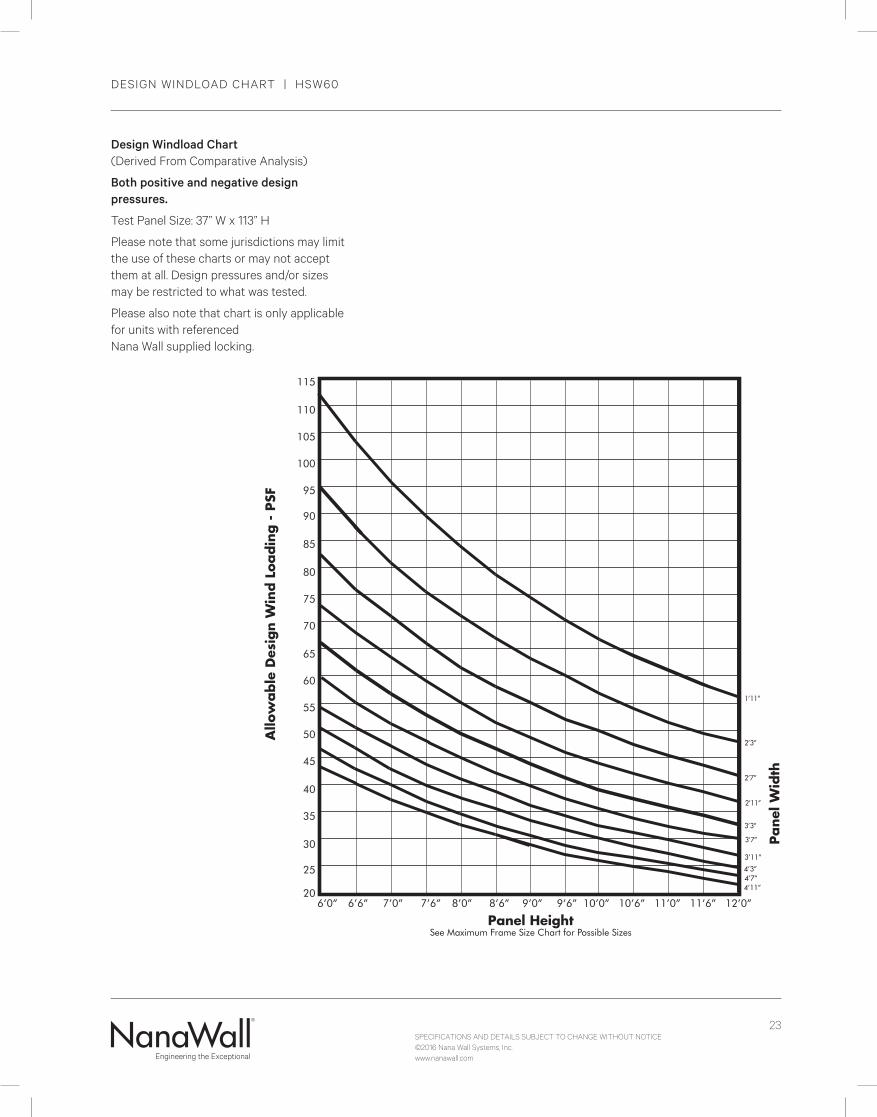
DESIGN WINDLOAD CHART | HSW60
Design Windload Chart (Derived From Comparative Analysis)
Both positive and negative design pressures.
Test Panel Size: 37” W x 113” H
Please note that some jurisdictions may limit the use of these charts or may not accept them at all. Design pressures and/or sizes may be restricted to what was tested.
Please also note that chart is only applicable for units with referenced Nana Wall supplied locking.

SPECIFICATIONS AND DETAILS SUBJECT TO CHANGE WITHOUT NOTICE©2016 Nana Wall Systems, Inc.www.nanawall.com
24