Name: Stephanus Michael Dwiprasetyo Widjanarko...
34
Name: Stephanus Michael Dwiprasetyo Widjanarko Student Number: s1028367 Company name: Vestas Wind System A/S; Technology R&D; Loads, Aerodynamics and Control Group Name of my mentor: Wout Ruijter, PhD City and Country: Aarhus, Denmark Period: August 2010 – November 2010 UTwente supervisor: Professor Harry Hoeijmakers, Engineering Fluid Dynamics, Mechanical Engineering.
Transcript of Name: Stephanus Michael Dwiprasetyo Widjanarko...

Name: Stephanus Michael Dwiprasetyo Widjanarko
Student Number: s1028367
Company name: Vestas Wind System A/S; Technology R&D; Loads, Aerodynamics and Control Group
Name of my mentor: Wout Ruijter, PhD
City and Country: Aarhus, Denmark
Period: August 2010 – November 2010
UTwente supervisor: Professor Harry Hoeijmakers, Engineering Fluid Dynamics, Mechanical Engineering.

Internship – Vestas Wind System A/S
Steady Blade Element Momentum Code for wind turbine design validation tool
Stephanus M.D. Widjanarko s1028367 Sustainable Energy Technology Universiteit Twente, Enschede, The Netherlands

Internship Report Steady Blade Element Momentum (BEM)
2 | P a g e
Preface
This internship assignment is conducted during August 2010 to November 2010 at the Department of Loads, Aerodynamics and Control Group, Vestas Wind System A/S, Denmark. This assignment would not be possible without help and contribution from people. I would like to express my gratitude to all of them.
1. Technology R&D in particular LAC Group at Vestas Wind System A/S who has given me a chance to experience and work in the state of the art design and research environment.
2. Wout Ruijter, PhD as the leading supervisor during my internship. Thank you very much for giving me a chance to work with you. Without your extreme patience and unique support, this piece of code would never be a reality.
3. Christian Gjerloev as the former director of Aerodynamics. Thank you for giving me a chance to work in your group.
4. Eugenio Rossi as the director of Aerodynamics. Thank you very much for the chance you have given to work in Aerodynamics team and get me involved in daily activities.
5. Kristian Godsk, Jonathan Adamsen, Jonas Romblad, Wout Ruijter and Sonia Salcedo as the awesome engineers in LAC Aero team. Thank you very much for your input and knowledge you have shared with me.
6. Susan Essien Etok, PhD in the Intellectual Property Right (IPR) LAC. Thank you very much for your input, suggestions and feedback for the report.
7. Kees Ruijter as the educational director at Twente University who has helped me tremendously during the application process.
8. Professor Harry Hoeijmakers in the Engineering Fluid Dynamics (EFD) Twente University for support, courage and input before and during the internship.
9. Jelle Ferwerda, PhD and Dorien van De Belt, PhD as the international coordinator and internship coordinator, respectively, for helping me to sort out the working permit issue in Denmark.
10. I would like to thank as well to Maria Castaneda, Andrea Redolfi, Roberto Zapata, Rebeca Rivera, Sonia Salcedo, Adriana Verde, Jovita Ivanaviciute, Wout Ruijter, Jonas Romblad and Saed Ehsani. You are awesome people who make me feel like home in Aarhus. Thank you very much for everything.
11. Finally, I would like to thank my parents, my brothers and my sisters in Indonesia. Thank you for your precious and sincere support and love that you always give to me.
Aarhus, 23 November 2010
Stephanus Michael Dwiprasetyo Widjanarko

Internship Report Steady Blade Element Momentum (BEM)
3 | P a g e
Summary
Efficient wind power generation is essential to compete with fossil fuel based power generation. The blade design problem is a balance of aerodynamic efficiency, loads, cost and mass with a large number of design variables associated to both internal and external shape and strong coupling among them. This introduces a need for a large number of iterations during the design process. The need of having tools that can be tuned becomes crucial. The objective of this assignment is to write low order accuracy code to evaluate wind turbine design especially blade design. Steady Blade Element Momentum (BEM) method is chosen for this assignment. Steady BEM is a very simplified model which combines 1 dimensional momentum theory and sectional theory from aircraft industries. Certainly, this model has many drawbacks because of the simplification in the derivation. Complex flow field around a wind turbine blade is assumed to be steady, rigid blade, uniform and straight incoming flow in BEM derivation. To consider this simplification, several corrections are implemented in the original BEM derivation. The tool is written in python programming language. The code is written in object oriented approach so that it is easier to modify or add some features if necessary later. The tool is then tested on NREL UAE Phase VI wind turbine. Several relevant parameters are then compared to see the different corrections which are implemented.
Internship Report Steady Blade Element Momentum (BEM)
4 | P a g e
Contents Preface .......................................................................................................................................................... 2
Summary ....................................................................................................................................................... 3
List of figures ................................................................................................................................................. 5
List of tables .................................................................................................................................................. 6
List of equations ............................................................................................................................................ 7
Introduction .................................................................................................................................................. 8
Methodology ................................................................................................................................................. 9
Brief theory of Blade Element Momentum (BEM)........................................................................................ 9
BEM corrections ...................................................................................................................................... 14
Code Design and Implementation .............................................................................................................. 18
Results and discussion ................................................................................................................................ 23
Future Work ................................................................................................................................................ 29
Conclusion ................................................................................................................................................... 30
References .................................................................................................................................................. 31
Appendix A .................................................................................................................................................. 33

Internship Report Steady Blade Element Momentum (BEM)
5 | P a g e
List of figures
Figure 1. Control volume around a wind turbine [12] ................................................................................ 10 Figure 2. Streamlines, axial velocity and pressure upstream and downstream rotor [12] ........................ 11 Figure 3. Blade Element Theory Geometry [17] ......................................................................................... 12 Figure 4. Control volume shaped as an annular element to be used in the BEM model [12] .................... 12 Figure 5. velocities at the rotor plane [12] ................................................................................................. 13 Figure 6. turbulent wake state [12] ............................................................................................................ 15 Figure 7. Class diagram of SBlade code ...................................................................................................... 18 Figure 8. Main data flow for SBlade calculation ......................................................................................... 22 Figure 9. lift coefficient value at different radial position .......................................................................... 25 Figure 10. drag coefficient value at different radial position ..................................................................... 25 Figure 11. Power curve of NREL UAE Phase VI turbine ............................................................................... 26 Figure 12. Axial induction factor of NREL UAE Phase VI ............................................................................. 27 Figure 13. Angle of attack of NREL UAE Phase VI turbine ........................................................................... 28 Figure 14. Axial induction factor of NREL UAE Phase VI turbine ................................................................ 29

Internship Report Steady Blade Element Momentum (BEM)
6 | P a g e
List of tables
Table 1. Basic machine parameters of UAE phase VI turbine ..................................................................... 23 Table 2. UAE phase VI blade properties ...................................................................................................... 24 Table 3. Aerodynamics coefficient data adjusted for post stall ................................................................. 24

Internship Report Steady Blade Element Momentum (BEM)
7 | P a g e
List of equations
Equation 1. thrust developed by pressure jump across the rotor .............................................................. 11 Equation 2. thrust and power relation from momentum theory ............................................................... 11 Equation 3. annular thrust and moment from momentum theory ............................................................ 13 Equation 4. annular thrust and moment from sectional theory ................................................................ 13 Equation 5. axial and tangential induction factor ....................................................................................... 14 Equation 6. wind turbine solidity ................................................................................................................ 14 Equation 7. Prandtl tip correction .............................................................................................................. 14 Equation 8. new tip correction proposed by Shen et al[18] ....................................................................... 15 Equation 9. Glauert high induction correction ........................................................................................... 15 Equation 10. Spera correction .................................................................................................................... 16 Equation 11. DTU high induction correction .............................................................................................. 16 Equation 12. Modified Glauert high induction correction [3] .................................................................... 16 Equation 13. RISOE high induction correction ............................................................................................ 17 Equation 14. Prandtl hub correction ........................................................................................................... 17

Internship Report Steady Blade Element Momentum (BEM)
8 | P a g e
Introduction
Efficient wind power generation is essential to compete with fossil fuel based power generation. The blade design problem is a balance of aerodynamic efficiency, loads, cost and mass with a large number of design variables associated to both internal and external shape and strong coupling among them. This introduces a need for a large number of iterations during the design process. The need of having tools that can be tuned becomes crucial.
Flow field around a wind turbine is very complex which involves unsteady, compressible, three dimensional, turbulent and separated flow. This complex flow phenomenon is influenced from far field condition, far upstream, far downstream and depends on small scale turbulent flow conditions around the blades. For CFD simulation, this means large simulation domain with fine spatial resolution is mandatory which makes full CFD simulation time consuming and expensive. CPU and memory used will also be very intensive during the simulation. There is an alternative method for calculating aerodynamic characteristics of a wind turbine blade using vortex method. This has the limitation that it cannot model viscous behavior since it is based on potential flow theory.
There is another method to evaluate aerodynamics properties of blade which is Blade Element Momentum (BEM) method. The BEM method is very popular in the wind industry for design and validation tool [1‐2]. Computational resources needed for BEM calculations are much less than other methods such as CFD or vortex method. Using the BEM method, it is possible to rapidly develop and test different blade configurations. In particular for this assignment, the code is designed to evaluate blade size and configuration. This code will give flexibility on turbine level optimization such as noise, power, pitch, etc. Once a preliminary result is obtained, the design could be studied in more detail using more advanced model like CFD.
Apart from BEM model advantages, there are several inherent drawbacks for calculating the effect of wind turbine wake using BEM theory [1, 3]. BEM theory combines momentum theory and sectional theory [4] invented from aircraft design. Several assumptions are taken for BEM modeling. One primary assumption is steady calculation; it is assumed that the airflow field around the airfoil is always in equilibrium and uniform. In reality, the airfoil takes time to adjust to different wake configuration as a result of a new incoming flow or a different turbine operating condition [3]. Sectional theory also assumes that flow is 2 dimensional where in reality spanwise flow occurs due to the centrifugal and Coriolis effects. This effect is essential especially in the area where the rotor loading gradient, hence radial pressure gradient, is high, e.g. at the root and at the tip. This is normally taken into account by involving 3‐D effect into the original 2‐D airfoil database. This model involves centrifugal, Coriolis and Himmelskamp effect [5]. Several models for 3‐D effect are available in the published literature [5‐7]. Skewed and yawed inflow are not considered in BEM theory where dynamic flow phenomenon occurs [1, 3].
Basic structural phenomena are not accounted which create error in predicting aerodynamics properties. Rigid blade is assumed in which the BEM theory fails when a large deflection out of the rotor plane occurs. This is due to the momentum equation being balanced in a plane parallel to the rotor. The

Internship Report Steady Blade Element Momentum (BEM)
9 | P a g e
large deflection out of the rotor plane will induce error in the aerodynamic calculation. Torsion also creates error in the local pitch angle value. The forces experienced by the blade will induce torsion where this effect is not accounted for in the BEM theory. The BEM theory also disregards the rotational wake pressure and the wake expansion. Extensive investigations have been carried out at RISOE recently published the result accounting a correction for the rotational wake and wake expansion effects [8‐11].
Another major concern about the BEM theory is that it combines differential and integral analysis at the same time. The momentum theory is derived in the integral form but later in the derivation, equations are used on the differential form where the stream tubes are assumed to be independent of each other (strip theory). Although this approach gives benefits in terms of rotor design optimization and robust model, this creates uncertainty especially when the rotor loading gradient is significant as in the case at the root and at the tip.
Methodology
The project is to develop tool to evaluate the wind turbine design. Aerodynamics properties of a given blade configuration (twist and chord distribution) are tested and evaluated using this tool. This tool is developed based on steady Blade Element Momentum (BEM). Different corrections are implemented to correct the simplification of BEM model.
The output parameters from the tool are separated into turbine level and blade level:
1. Turbine level: Annual Energy Production, Power Curve, Noise, global power and thrust coefficient, thrust.
2. Blade level: axial induction factor, tangential induction factor, relative velocity, local power coefficient, local thrust coefficient, angle of attack, lift coefficient and drag coefficient.
In this report, NREL UAE phase VI turbine is tested and discussed.
Brief theory of Blade Element Momentum (BEM)
The Blade Element Momentum (BEM) theory is one of the oldest and the most common used method to calculate induced velocities on wind turbine rotor plane [1, 9]. This theory was introduced by Betz and Glauert in 1935 and this is the extension of the actuator disc theory; the work done by Rankine and Froude in the late 19th century [3, 12]. The BEM theory is the combination of 2 theories: the momentum theory and the blade element (sectional) theory. In the momentum theory, the actual geometry of the rotor – number of blades, twist and chord distribution and the type of airfoil – is neglected. The local event taking place at blades is considered in the sectional theory where aerodynamic forces are calculated based on the local flow condition. This theory assumes that blades could be divided into annular elements and independent of surrounding elements. There is no flow across the lateral boundary since it consists of streamlines. This simplified model of rotor aerodynamics is able to
Internship Report Steady Blade Element Momentum (BEM)
10 | P a g e
calculate steady loads (the moment and the thrust) after summing the elemental forces, hence the thrust and the power, for varieties of wind speed, rotational speed and pitch angle. The BEM formulation will be described briefly in the following paragraph.
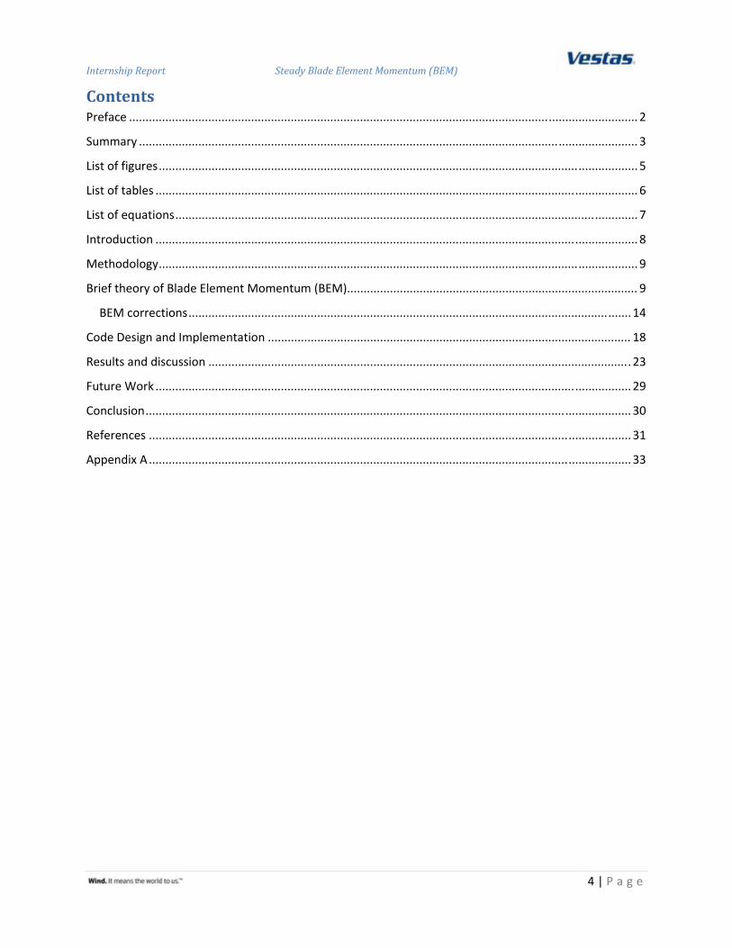
Before deriving the BEM theory, it is useful to derive the one dimensional theory for an ideal rotor. The ideal rotor extracts the kinetic energy and converts it to the mechanical energy. The rotor is modeled as a permeable disc (a semi transparent disc to flow) which creates a pressure discontinuity across the rotor plane. Friction and rotational velocity are not considered in the derivation. The rotor will slow down the wind speed from the far upstream velocity (Vo) to u at the rotor plane and to u1 in the wake. The schematic of the ideal rotor disc can be seen below where p(x) is pressure applied to the control volume, T is the thrust developed due across the rotor, A is the rotor swept area, A1 is the wake expansion area and x is the distance measured from the far upstream.
Figure 1. Control volume around a wind turbine [12]
Because the wind speed slows down as it approaches the rotor, the streamline must be diverged as shown in the picture above. Slightly upstream of the rotor there is a small pressure rise from the atmospheric pressure before discontinuous pressure drop across the rotor. Downstream of the rotor the pressure increases continuously back to the atmospheric level. Besides this ideal rotor assumption, homogenous, incompressible, inviscid fluid, steady and uniform flow over the rotor plane is assumed. The pressure and velocity distribution can be seen in the figure below.

Internship Report Steady Blade Element Momentum (BEM)
11 | P a g e
Figure 2. Streamlines, axial velocity and pressure upstream and downstream rotor [12]
The thrust developed at the rotor could be calculated using simple formula
∆ .
Equation 1. thrust developed by pressure jump across the rotor
where Δp is the pressure jump across the rotor and A is the rotor swept area. Making the mass and momentum balance for the control volume, one yields the following relationship to calculate power and thrust developed by the turbine.
2 1
2 1
Equation 2. thrust and power relation from momentum theory
where ρ is the air density, Vo is the free stream velocity, A is the rotor swept area and a is the ratio of velocity at the rotor plane and upstream velocity which is known as axial induction factor. The detailed derivation could be read in the literatures [12‐13].
The second part of the BEM theory is the blade element theory or the sectional theory. This method originated from the aircraft industry [4, 14]. This theory is used for turbine blade design although the blade cross sectional shape is different than aircraft wings. Sectional aerodynamic forces (forces in the rotor plane) causes change of the momentum of the airflow (and hence the induction) [15]. In theory, only lift is involved in axial induction calculation. The reason is that drag has a very localized effect especially in the viscous wake [15]. Another reason is that circulation theory is used to formulate the tip correction. Wilson and Lissaman also argued that including the drag term in the calculation will destroy
Internship Report Steady Blade Element Momentum (BEM)
12 | P a g e
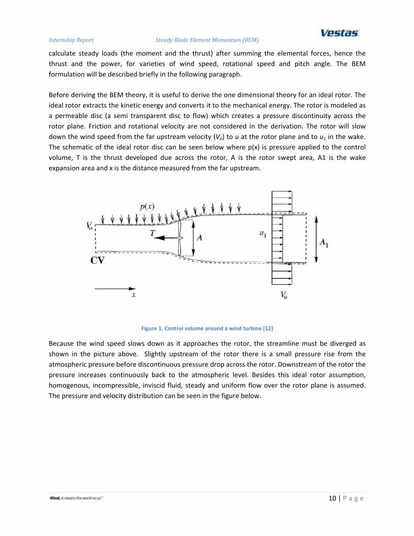
the orthogonality of the relative velocity and the induced velocity [3, 16]. The blade element geometry can be seen in the picture below.
Figure 3. Blade Element Theory Geometry [17]
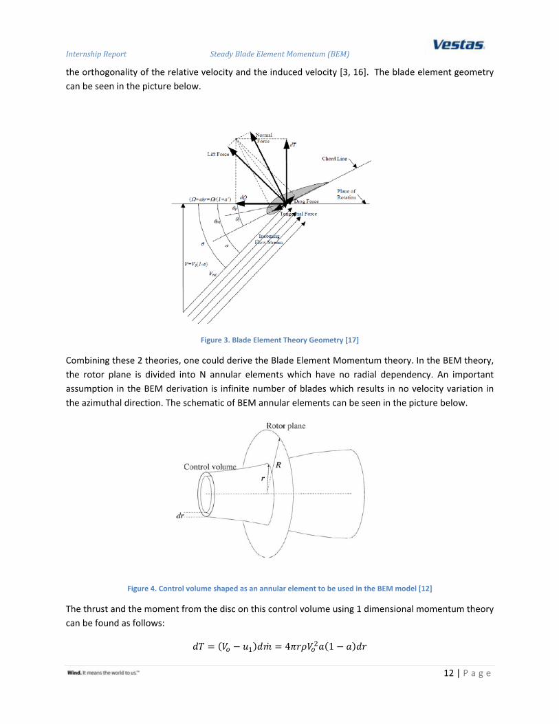
Combining these 2 theories, one could derive the Blade Element Momentum theory. In the BEM theory, the rotor plane is divided into N annular elements which have no radial dependency. An important assumption in the BEM derivation is infinite number of blades which results in no velocity variation in the azimuthal direction. The schematic of BEM annular elements can be seen in the picture below.
Figure 4. Control volume shaped as an annular element to be used in the BEM model [12]
The thrust and the moment from the disc on this control volume using 1 dimensional momentum theory can be found as follows:
4 1

Internship Report Steady Blade Element Momentum (BEM)
13 | P a g e
4 1
Equation 3. annular thrust and moment from momentum theory
where ω is the rotor rotational speed, r is the radial distance measured from the rotation axis and a’ is tangential induction factor. Tangential induction factor exists due to the rotational wake downstream of the rotor. The left hand site equation could be found from the sectional theory. The velocity seen by the blade can be seen in the picture below.
Figure 5. velocities at the rotor plane [12]
Θ is local pitch of the blade and φ is the the angle between the rotor plane and the relative velocity. Local pitch is the combination of pitch angle, θp, and the twist of the blade, β, as θ = θp + β. Φ is the angle between the plane of rotation and the relative velocity. The local angle of attack is given by the following relation, α = φ – θ. The normal and tangential forces on the control volume thickness dr are:
12
1
12
1 1sin cos
Equation 4. annular thrust and moment from sectional theory
where B is the number of blades, CT and CN is the tangential and normal force coefficient relative to the rotor plane. Combining Equation 3. annular thrust and moment from momentum theory and Equation 4. annular thrust and moment from sectional theory, one will yield the relation to calculate the axial and the tangential induction factor
14 sin 1
14 sin cos 1

Internship Report Steady Blade Element Momentum (BEM)
14 | P a g e
Equation 5. axial and tangential induction factor
where σ is the solidity defined as the fraction of the annular area in the control volume which is covered by blades.
2
Equation 6. wind turbine solidity
BEM corrections
One major limitation of the original BEM theory is that there is no influence of vortices shed from the blade tips into the wake on the induced velocity field [3]. These tip vortices create multiple helical structures in the wake and they play major role in the induced velocity distribution at the rotor. The wake effect on induced velocity is significant near the tips of the blades where the power production is very important. To correct this simplification, Prandtl tip correction is introduced. Prandtl developed the correction based on the helical vortex wake pattern as vortex sheets that are convected by the mean flow and have no direct effect on the wake itself. Prandtl correction factor is expressed
2cos
2 sin
Equation 7. Prandtl tip correction
where R is the tip radius, r is the radial distance measured from the rotation axis, φ is the angle between the rotor plane and the relative velocity. Shen et al has proposed a new tip correction with the intention to have zero force at the tip due to pressure equalization from suction side and pressure side of the blade [16, 18]. The other reason is that classic tip correction model is inconsistent as it approaches the tip area. They analyzed that axial induction factor always tends to unity when approaching the tip which means zero velocity at the tip. This is not physical [18]. The new tip formula and new induction factor formula read as follows

Internship Report Steady Blade Element Momentum (BEM)
15 | P a g e
Equation 8. new tip correction proposed by Shen et al[18]
Other corrections take into account when 1 dimensional momentum theory fails due to turbulent wake state [12]. When the induction factor value is higher than approximately 0.4, the momentum theory breaks down. At this value, the free shear layer at the edge of the wake becomes unstable. The velocity jump from the wake to the free stream is too high and eddies are formed which transport momentum from the outer flow into the wake. The situation could be sketched as follows
Figure 6. turbulent wake state [12]
There are several high induction corrections which are available in the literature.
1. Glauert correction The classic Glauert relation reads as follows [12]
Equation 9. Glauert high induction correction
2. Spera correction This spera correction reads as follows [12]

Internship Report Steady Blade Element Momentum (BEM)
16 | P a g e
Equation 10. Spera correction
3. DTU course correction DTU high induction correction is obtained from wind energy course from DTU [19]
Equation 11. DTU high induction correction
4. Modified Glauert
This modified Glauert relation is a combination of the tip loss and the Glauert correction [3]. The motivation is that induced velocity near the tip is high; therefore, the possibility of a turbulent wake near tip increases. Thus, the total induced velocity calculation must use the combination of the tip loss and Glauert relation.
Equation 12. Modified Glauert high induction correction [3]
5. RISOE empirical relation Recently, RISOE published its own empirical relation for the high induction correction [2, 8‐9, 11]. The formula reads as follows

Internship Report Steady Blade Element Momentum (BEM)
17 | P a g e
Equation 13. RISOE high induction correction
where k3 = 0.08921, k2 = 0.0545, k1 = 0.25116
To correct the induced velocity resulting from a vortex being shed near the hub of the rotor, the hub loss is introduced. The hub loss is similar with the Prandtl tip correction. The result of this correction is the opposite of the result published by RISOE [11]. Rotational wake creates negative pressure at the hub region which accelerates the flow and reduces axial induction factor. However, introducing the hub loss model will increase the axial induction factor since the axial induction factor is inversely proportional to the Prandtl hub loss factor. The equation reads as follows
2cos
2 sin
14 F F sin
1
Equation 14. Prandtl hub correction
where Rhub is the distance of the first annular element measured from the rotation axis.
There are several other corrections as well which will be implemented in the original BEM code. Each of them will be explained below.
1. Wind shear correction This correction considers the uniform flow assumption. Due to the surface friction, boundary layer develops on the earth surface. The formula and the implementation can be seen in the Appendix.
2. Turbulence of the incoming wind This correction considers the turbulence of the incoming wind. This is empirical relation developed in Vestas to match the experimental data.
3. Other corrections In BEM derivation, rotor is assumed straight and rigid. Coning and tilt angle exist to maintain the minimum tower clearance. Furthermore, blade is flexible and bending occurs during the operation. These will affect the energy produced by the turbine. A simple correction based on reduced rotor swept area is implemented.

Internship Report Steady Blade Element Momentum (BEM)
18 | P a g e
Code Design and Implementation
The code is written in Python which is an open source programming language. Besides, python is a high level programming language and support object oriented programming. Object oriented Programming (OOP) is a programming paradigm that views computer program as assemblies of interacting objects. Such objects can possess both functionality and data. OOP facilitates a systematic engineering approach where a complex problem is divided into basic logical parts of which the behavior can be formulated readily. The class schematic could be seen in the diagram below. For the calculation, one could choose among different codes which are available as well as an option to include or exclude drag in the calculation.
Figure 7. Class diagram of SBlade code
1. Input data class This class manages AERO input file. It reads all the necessary input data needed for BEM calculation. The main input data consists of turbine, rotor and blade parameter. Turbine parameter consists of gear and generator losses. Rotor parameter consists of number of blades, coning, tilt, pitch angle, generator speed, wind shear and hub height variable. Blade parameter consists of blade shape profile (i.e twist chord distribution and blade airfoil profile). Additional input data consists of statistic and environmental parameter. This class also prepares aerodynamic tables at each radial position using thickness based linear interpolation.

Internship Report Steady Blade Element Momentum (BEM)
19 | P a g e
2. Airfoil class
This class manages airfoil tables which are prepared by input data class. It interacts with section class to obtain lift coefficient and drag coefficient for BEM calculation in the section class. To obtain lift and drag coefficient, cubic spline interpolation method is used. It also interacts with noise class to obtain maximum lift coefficient, minimum lift coefficient and angle of attack at zero lift coefficients for detailed noise calculation. Brent algorithm is used to find those values. Brent algorithm combines root bracketing, bisection method and inverse quadratic interpolation. It is claimed to be as reliable as bisection method and can be as quick as less reliable method such as inverse quadratic interpolation [14].
3. Section class This class manages core BEM algorithms. It consists of several BEM algorithms which are available in the literature. There are 7 codes which are written in this class. Drag term is an option in the calculation. The brief explanation could be found below.
a. AERO code This is in house developed BEM code. In this code, drag term is not included in the default setting. In AERO, classic Prandtl tip loss and in house high induction correction are used.
b. Plain BEM This is plain Blade Element Momentum code with no corrections implemented.
c. DTU code The core algorithm is from Aerodynamics of Wind Turbine [12]. Classic Prandtl tip and DTU course high induction correction are implemented. Prandtl hub loss model is also implemented in this code.
d. NTip code The core algorithm is from Shen et al and Hansen et al [16, 18]. They proposed new tip correction with the intention to have zero force at the tip and non‐zero axial velocity at the tip. They also claim that tip corrected airfoil database is no longer needed when implementing the correction. Rotational correction is not needed as well since rotational effect at the tip is negligible. Hence, 2 dimensional data from windtunnel experiment could be used directly. They also proposed a new formula to calculate axial and tangential induction factor.
e. Qblade code Qblade is an open source turbine simulator and design tool from TU Berlin [20]. New tip correction is used but with classic way of calculating axial and tangential induction factor. Modified glauert high induction correction is used.
f. Risoe code The core algorithm is the same as in DTU code. This code is not yet available because rotational and wake expansion correction is not yet ready. RISOE empirical relation for high induction correction is used. RISOE also published several articles to correct the rotational and wake expansion effect [2, 8‐11].

Internship Report Steady Blade Element Momentum (BEM)
20 | P a g e
g. Spera code The core code is similar as in DTU code. However, for high induction correction, a modified Glauert correction (Spera correction) is used.
4. Blade class This class manages blade properties and carries out calculation over the blade span. Sectional loadings which are obtained from the lower class (section class) are integrated numerically over the blade span to obtain the developed power and thrust. RISO rotational and wake expansion correction is available in this class although currently this does not work. This class also prepares input for detailed noise calculation later by extrapolating linearly angle of attack and relative velocity at the tip. It also prepares angle of attack and relative velocity at 87% of the blade radius for global noise calculation based on RISOE wind tunnel measurement.
5. Rotor class This class manages rotor properties and calculates power with cone, tilt, wind shear and bending correction. Tilt, cone and bending correction are based on reduced rotor swept area. It takes the integrated loadings from the blade class. The values are multiplied by the number of blades. This class also calculates global power and thrust coefficient. To calculate bending correction, additional input file is needed. First mode bending and tip deflection data are required. These input file is processed to obtain spline data (bending shape) for a particular wind speed. Splines data are transformed for coning angle. Afterwards, tilt correction is added and rotor swept area is calculated. Since only discrete data is available for tip deflections, cubic spline interpolation is implemented to calculate rotor swept area at a given wind speed.
6. Controller class This class manages controller variable. This class takes rotor speed table and pitch angle table from the input data class then interpolates the value for a given wind speed.
7. Turbine class This class calculates power generated by the generator. All losses coming from generator and gearbox are calculated in this class. The turbulence effect of the incoming wind on the generator power is considered in this class. Generator power after the turbulence effect is the input for Annual Energy Production (AEP) calculation. This class interacts with noise class to make noise calculation.
8. Noise class This class manages global noise calculation and detailed noise calculation. For global noise calculation, the formula is from measured data on V90 profile. Turbulence inflow noise, turbulent boundary layer trailing edge noise and trailing edge bluntness vortex shedding noise are calculated in this class.

Internship Report Steady Blade Element Momentum (BEM)
21 | P a g e
9. Optimization class This class manages calculation to find the optimized pitch value. This is a constrained optimization problem where nominal generator power is the constrained value. The constrained problem is transformed to unconstrained problem by adding penalty function upon violation of a constrained value [21‐22]. In this case, static penalty function is implemented. Step penalty is introduced upon violation of the constrained value. Currently, non gradient based optimization scheme is used to calculate the optimized pitch value. Downhill simplex algorithm is chosen for this case. This algorithm is based on Nelder Mead method which is a direct search method. It Is based on evaluating a function at the vertices of a simplex then iteratively shrinking the simplex as better points are found until some desired bounds is obtained [23].
10. Statistical distribution class This class manages Weibul distribution and normal distribution for calculating annual energy production and turbulence effect, respectively. This class takes the input value from the input data class.

Internship Report Steady Blade Element Momentum (BEM)
22 | P a g e
The main data flow could be seen more clearly in the diagram below.
Figure 8. Main data flow for SBlade calculation

Internship Report Steady Blade Element Momentum (BEM)
23 | P a g e
Results and discussion
Due to confidentiality of the data, no Vestas turbine is used to test the code. Instead, UAE phase 6 turbine is used. UAE stands for Unsteady Aerodynamics Experiment which is intended to provide information needed to quantify the full scale, 3‐dimensional aerodynamic and structural behavior of the horizontal‐axis wind turbine. The test was conducted in NASA AMES Wind Tunnel Facility [24]. The detailed specification of UAE phase 6 turbine could be found in the literature [17, 24]. Basic machine parameter for calculation is listed below:
Number of blades 2 Blade radius 5.532 m Hub height 12.192 m Rotor rotational speed 71.63 rpm Cut in wind speed 6 m/s Power regulation stall Tilt and cone angle 0o Blade tip pitch angle 4.815o
Table 1. Basic machine parameters of UAE phase VI turbine
Blade properties could be seen in the table below.
Radial distance (m)
span station (r/5.532m)
chord length (m)
twist (degree)
thickness (m)
Airfoil profile
0.508 0.092 0.218 0 0.218 cylinder 0.66 0.12 0.218 0 0.218 cylinder 0.883 0.16 0.183 0 0.183 cylinder 1.008 0.183 0.349 6.7 0.163 transition 1.067 0.193 0.441 9.9 0.154 transition 1.133 0.205 0.544 13.4 0.154 transition 1.257 0.227 0.737 20.04 0.154 transition 1.343 0.243 0.728 18.074 20.95% S809 1.51 0.273 0.711 14.292 20.95% S809 1.648 0.298 0.697 11.909 20.95% S809 1.952 0.353 0.666 7.979 20.95% S809 2.257 0.408 0.636 5.308 20.95% S809 2.343 0.424 0.627 4.715 20.95% S809 2.562 0.463 0.605 3.425 20.95% S809 2.867 0.518 0.574 2.083 20.95% S809 3.172 0.573 0.543 1.15 20.95% S809 3.185 0.576 0.542 1.115 20.95% S809 3.476 0.628 0.512 0.494 20.95% S809 3.781 0.683 0.482 ‐0.015 20.95% S809 4.023 0.727 0.457 ‐0.381 20.95% S809 4.086 0.739 0.451 ‐0.475 20.95% S809

Internship Report Steady Blade Element Momentum (BEM)
24 | P a g e
4.391 0.794 0.42 ‐0.92 20.95% S809 4.696 0.849 0.389 ‐1.352 20.95% S809 4.78 0.864 0.381 ‐1.469 20.95% S809 5 0.904 0.358 ‐1.775 20.95% S809
5.305 0.959 0.328 ‐2.191 20.95% S809 5.532 1 0.305 ‐2.5 20.95% S809
Table 2. UAE phase VI blade properties
Aerodynamics coefficients are not available experimentally at all radial positions. List of aerodynamic data is shown below:
Airfoil Adjusted for post stall at radial span position (r/R)
Reynolds number
S809 0.129 750000 S809 0.185 750000 S809 0.242 750000 S809 0.298 750000 S809 0.354 750000 S809 0.410 750000 S809 0.6 750000 S809 0.8 750000 S809 outboard 750000
Table 3. Aerodynamics coefficient data adjusted for post stall
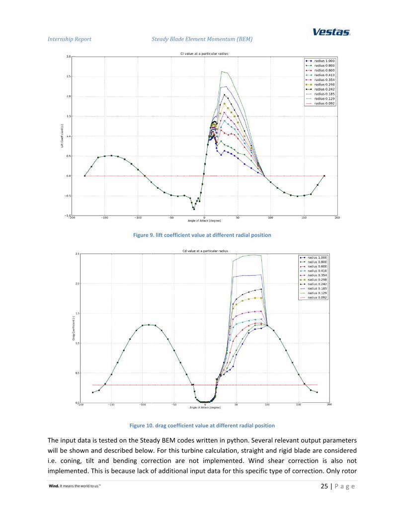
Linear interpolation based on radial position instead of thickness is implemented for UAE phase VI turbine calculation since radial position based aerodynamic coefficient is provided. The 2D data is adjusted for 3D effect and extrapolated to ‐180o to 180o. Distribution of lift and drag coefficient over the blade can be seen in the graph below. For clarity reason, not all radial position value is shown.
Internship R
The inputwill be shi.e. coninimplemen
Report
t data is testeown and desng, tilt and nted. This is b
Figure 9
Figure 10
d on the Steascribed belowbending corrbecause lack o
Steady Blade El
9. lift coefficient
0. drag coefficien
ady BEM codew. For this turrection are of additional
lement Moment
t value at differe
nt value at diffe
es written in rbine calculatnot implemeinput data fo
tum (BEM)
ent radial positi
erent radial posi
python. Sevetion, straight ented. Wind or this specifi
ion
ition
eral relevant oand rigid blashear correc type of corr
25 | P
output paramade are considection is alsorection. Only
a g e
meters dered o not rotor

Internship Report Steady Blade Element Momentum (BEM)
26 | P a g e
power is considered in this report which means gear and generator losses are not considered. Annual Energy Production (AEP) is not calculated as well since the turbulence effect on the generator power is not calculated.
Figure 11. Power curve of NREL UAE Phase VI turbine
From the graph above, it could be seen that new tip correction is completely off from the other codes. This might be due to new formula to calculate axial and tangential induction factor and it makes the calculation unstable and diverged. Apart from the new tip code, the rest of the codes give quite similar result. Only plain BEM code deviates from the other BEM with corrections. The deviation is due to tip correction is not implemented in the calculation.
0
2
4
6
8
10
12
14
0 5 10 15 20 25 30
Rotor p
ower [k
W]
wind speed [m/s]
Power Curve NREL UAE Phase VI
NREL UAE VI AERO
NREL UAE VI Plain BEM
NREL UAE VI DTU
NREL UAE VI QBlade
NREl UAE VI Spera
NREL UAE VI NTip

Internship Report Steady Blade Element Momentum (BEM)
27 | P a g e
Figure 12. Axial induction factor of NREL UAE Phase VI
In this graph, it could be seen again that new tip code is not stable and give non‐sense result. Drag term is not included in the calculation of axial induction factor. DTU and Spera correction use root correction and the effect could be seen clearly where the axial induction factor shifts up at the inboard part of the rotor. The effect of the tip correction could be seen as well where axial induction factor with classical Prandtl tip correction increases quite significantly at the outboard part of the rotor. New tip correction which is also implemented in the QBlade code shows less induction factor at the outboard part of the rotor whereas plain BEM code predicts the smallest axial induction factor at the tip. The trend of the result is similar with one in the literature [18]. However, one might notice that although all codes predict power curve quite similarly, the axial induction factor value deviates quite significantly among one another. This is due to power curve is the integrated quantities consisting of contributions from all local properties. Another reason might be due to balance of local properties at the inboard and outboard part of the rotor.
0
0.05
0.1
0.15
0.2
0.25
0.3
0 1 2 3 4 5 6
axial ind
uction
factor [‐]
radial position [m]
Axial induction factor NREL UAE Phase VI at 10 m/s
Drag = Off
NREL UAE VI AERO
NREL UAE VI Plain BEM
NREL UAE VI DTU
NREL UAE VI QBlade
NREL UAE VI Spera
NREL UAE VI NTip

Internship Report Steady Blade Element Momentum (BEM)
28 | P a g e
Figure 13. Angle of attack of NREL UAE Phase VI turbine
In this graph, angle of attack along the blade span is shown. It shows once more that new tip correction is unstable and gives non‐sense result. Blade section starts at radius 1.3 m and angle of attack drops gradually as it approaches outboard part of the rotor. QBlade code predicts a slightly higher angle of attack compare to the rest of the code although the trend is similar with others.
0
10
20
30
40
50
60
70
80
90
0 1 2 3 4 5 6
angle of attack [degree]
radial position [m]
Angle of attack UAE Phase VI at 10 m/s
NREL UAE VI AERO
NREL UAE VI Plain BEM
NREL UAE VI DTU
NREL UAE VI NTip
NREL UAE VI QBlade
NREL UAE VI Spera

Internship Report Steady Blade Element Momentum (BEM)
29 | P a g e
Figure 14. Axial induction factor of NREL UAE Phase VI turbine
In this graph, it could be seen again that new tip code is not stable and give non‐sense result. Drag term is included in the calculation of axial induction factor except AERO code. It shows that drag term has a significant effect at the inboard part of the rotor. It predicts a higher value of axial induction factor when drag term is included at the inboard part of the rotor. However, including drag term in the calculation does not change the value of the induction factor at the tip significantly.
Future Work
This code is far from perfect. Many features could be implemented to improve the quality of the result and keeping the fundamental advantage of BEM method which is low computational cost. Several features could be added to this original code. They are:
1. Implementing rotational wake and expansion wake. Recently, RISOE has proposed the algorithm and the implementation accounting the rotational wake effect and the expansion wake effect. When wake rotation is included, less axial induction (increased velocity) is seen. The pressure is reduced towards the rotor centre when the rotation wake is included. This reduced pressure will accelerate the flow and increase the velocity above the free stream value. When wake
0
0.05
0.1
0.15
0.2
0.25
0.3
0 1 2 3 4 5 6
axial ind
uction
factor [‐]
radial position [m]
Axial induction factor NREL UAE Phase VI at 10 m/s
Drag = ON
NREL UAE VI AERO
NREL UAE VI Plain BEM
NREL UAE VI DTU
NREL UAE VI NTip
NREL UAE VI QBlade
NREL UAE VI Spera

Internship Report Steady Blade Element Momentum (BEM)
30 | P a g e
expansion is included, there is reduced inflow at the outboard part of the rotor [2, 9‐11]. The BEM result is expected to become more realistic when these 2 corrections are implemented.
2. Implementing winglet correction. This special feature is not accounted in the BEM code but has become a trend in the wind industry to include winglet to reduce the tip vortex strength. This correction could be done with the help of CFD. After obtaining result from CFD, curve fitting technique could be used to fit the data (e.g. axial induction factor, tangential forces or normal forces) with the result from the BEM calculation.
3. Implement torsional stiffness. Initial calculation of the local force is used as an input to calculate torsional deflection. Afterwards, sectional loads are recalculated with new pitch value. This correction is expected to consider the torsional flexibility of the blade.
4. For generating airfoil database, shape interpolation instead of thickness or radial interpolation could be implemented by using XFoil. Aerodynamic parameters of a specific type of airfoil are function of Reynolds number, Mach number and geometrical shape for a particular value of angle of attack [4]. Interpolating based on shape is more realistic instead of using thickness interpolation.
5. This code takes significant amount of time to calculate the properties especially when optimization feature is turned on. AERO code works faster compare to the other codes. This is partly due to conservative approach of updating new value during the iteration. Low relaxation factor is used to ensure stability and convergent behavior during the iteration.
Conclusion
Various correction methods are implemented and compared within the BEM code. Conclusions can be drawn upon examining the result of different corrections:
1. Power curve seems fairly insensitive for different type of corrections method. As explained in the result and discussion section, this is due to balance of inboard and outboard part of the rotor. Other reason is that power curve is integrated quantities of all sectional properties.
2. Axial induction factor varies significantly to different type of corrections methods especially at the outboard and inboard part of the rotor. This affects blade design parameter especially twist and chord distribution.
3. More detailed physical model (e.g. panel code or CFD code) is needed to conclude which correction models agree better with reality. Providing that detailed physical model is available, BEM corrections could be tuned to match better with higher order code.

Internship Report Steady Blade Element Momentum (BEM)
31 | P a g e
References
1. Imamura, H. Aerodynamics of Wind Turbines. 2009 [cited 2010 29 November 2010]. 2. Madsen, H.A., et al., A detailed investigation of the Blade Element Momentum (BEM)
model based on analytical and numerical results and proposal for modification of the BEM model. Journal of Physics, 2007.
3. Moriarty, P.J. and A.C. Hansen, AeroDyn Theory Manual. 2005, National Renewable Energy Laboratory.
4. John D. Anderson, J., Fundamentals of Aerodynamics. Anderson Series. Vol. Fourth Edition. 2007: McGraw‐Hill International Edition.
5. Montgomerie, B., Methods for root effects, tip effects and extending the angle of attack range to 180 degree with application to aerodynamics for Blades on wind turbines and propellers, in FOIR1305. 2004, FOI: Swedish Defence Research Agency.
6. Bak, C., J. Johansen, and P.B. Andersen, Three Dimensional Corrections of Airfoil Characteristics Based on Pressure Distributions, in EWEC2006. 2006: Athens, Greece.
7. Lindenburg, C., Modelling of rotational augmentation based on engineering considerations and measurements, in EWEC2004. 2004: London.
8. Madsen, H.A., et al., Validation and modification of the Blade Element Momentum theory based on comparisons with actuator disc simulation. Wind Energy, 2010.
9. Doessing, M., A detailed investigation of the corrected BEM method and the potential for improving blade design, in EWEC2009. 2009.
10. Madsen, H.A., et al., Inboard rotor/blade aerodynamics and its influence on blade design, in Research in Aeroelasticity. 2006, RISOE National Laboratory.
11. Madsen, H.A., Two modifications of the BEM method based on validation with results of actuator disc simulations, in RISO Report. 2008.
12. Hansen, M.O.L., Aerodynamics of Wind Turbine: Second edition. 2008: Earth Scan. 13. Manwell, J.F., J.G. McGowan, and A.L. Rogers, Wind Energy Explained: Theory, Design
and Application. 2002: John Wiley and Sons, LTD. 14. Weisstein, E.W. Brent's Method: MathWorld. 1992 18 November 2010]. 15. Snel, H., Wind Energy Course at Universiteit Twente: Aerodynamics of Wind Turbines,
Energy Extraction, ECN Wind Energy. 16. Hansen, M.O.L. and J. Johansen, Tip studies using CFD and Comparison with Tip Loss
Models. Wind Energy, 2004. 17. Jonkman, J.M., Modeling of the UAE Wind Turbine for Refinement of FAST_AD. 2003,
National Renewable Energy Laboratory. 18. Shen, W.Z., et al., Tip Loss Corrections for Wind Turbine Computations. Wind Energy,
2005. 19. Presentation: Crashcourse DTU: Blade Element Momentum, Denmark Technical
University, DTU. 20. Marten, D., QBlade v0.01: Guidelines. 2010. 21. Smith, A.E. and D.W. Coit, Penalty Functions. Section C 5.2 of Handbook of
Evolutionary Computation. 1995. 22. Presentation: Optimization in Engineering design: Penalty and Barrier Methods,
Georgia Institute of Technology System Realization Laboratory.

Internship Report Steady Blade Element Momentum (BEM)
32 | P a g e
23. Weisstein, E.W. NelderMead Method: MathWorld. 1992 [cited 2010 18 November 2010].
24. Hand, M.M., et al., Unsteady Aerodynamics Experiment Phase VI: Wind Tunnel Test Configurations and Available Data Campaigns. 2001, National Renewable Energy Laboratory.

Internship Report Steady Blade Element Momentum (BEM)
33 | P a g e
Appendix A
To run the software, open test.py and write the following command line:
run_and_create_out_table(filename,code,drag)
where:
‐ Filename: AERO input file Code: choose number between 1 and 7. The detailed description of each code is in the
‐ Code Design and Implementation. ‐ Drag: choose 0 (drag is not included) or 1 (drag is included)
This command line will read the aero input file and create the output excel file with the name of:
filename_code_(1‐7)_out.xls