
NAF-Duball ball valves Fk 41.61(23)GB - Fagerberg · (PED 97/23/EG) module H, category III. ......
12
1 Primary characteristics NAF-Duball is a full-bore ball valve which, due to its design and combination of materials, is equally suitable for use as control valve, on/off control valve or shut-off valve. The NAF-Duball is supplied as standard in stainless steel. Also available in other materials e.g. Hastelloy C. The valve has: · an easy-to-service arrangement, due to the off- center joint face of the valve body, which allows for easy replacement of the ball and seals, without the need for removing the stem and actuator. · a floating ball that seals in both directions of flow and at low differential pressures. For tight valve at differential pressures below 0,5 bar consult NAF. · sturdy, blowout-proof rigidly journalled stem and a drive arrangement between the ball and stem that transmits torque evenly · stem seal with maintenance-free O-ring seals or stuffing box · metal-to-metal Alloy 6 seat rings or soft, enclosed carbon reinforced PTFE seat rings. · a range of materials available for the ball · a wide range of optional versions, over and above those described in the catalogue sheet · the NAF standard for mounting the actuator, which simplifies installation and results in a compact valve/actuator unit. CE-marked according to Pressure Equipment Directive (PED 97/23/EG) module H, category III. For module H1, category IV contact NAF Applications NAF-Duball can be used both as a control valve and as a shut-off valve, in a wide variety of applications and in different operating modes.The valve represents a concrete result of our product philosophy which is focused on functionality, high quality and low life cycle costs, and is based on concentrating our range to a limited number of valve types, but all of them suitable for a wide variety of applications. The excellent characteristics of NAF-Duball are particularly beneficial under the most arduous operating conditions in the process industry, where difficult media and demanding pressure conditions make severe demands on the design, materials and performance. NAF-Duball is recommended for applications in the fol- lowing branches: - Pulp and Paper - Chemical and Petro Chemical - Oil and gas - Power stations - Steel works NAF-Duball ball valves DN 25 - 400, Size 1” - 16” PN 10 - 40, ANSI Class 150 - 300 Fk 41.61(23)GB 11.02 Technical specification for standard design Material: EN 1.4408 Size range: DN 25—400 (1”—16”) Pressure ratings: PN 10—40 ANSI Class 150—300 Face-to face lengths: PN 10: EN 558-1 series 12 (SSG 1042) ANSI 150: ANSI B 16.10 Class 150 long PN 25—40: EN 558-1 series 4 (SSG 1043) ANSI 300: ANSI B 16.10 Class 300 short Size 1”—12” Class 300 long Size 14”—16” Valve design: ANSI B16.34 och EN 12 516 Installation method: Flanges to DIN or ANSI B 16.5 Temperature range: -30 - 350 O C, see graph on page 2 Test pressure: 1,5xPN with valve open 1,1xPN with valve closed Sealing class: Testing medium is water. PTFE seats EN 12266-1 Rate A Metal seats IEC 534-4 Class V ANSI / FCI70-2 At request for test fluid air contact NAF for more infor- mation
Transcript of NAF-Duball ball valves Fk 41.61(23)GB - Fagerberg · (PED 97/23/EG) module H, category III. ......

1
Primary characteristicsNAF-Duball is a full-bore ball valve which, due to its design and combination of materials, is equally suitable for use as control valve, on/off control valve or shut-off valve. The NAF-Duball is supplied as standard in stainless steel.Also available in other materials e.g. Hastelloy C.
The valve has:· an easy-to-service arrangement, due to the off-
center joint face of the valve body, which allows for easy replacement of the ball and seals, without the need for removing the stem and actuator.
· a floating ball that seals in both directions of flow and at low differential pressures. For tight valve at differential pressures below 0,5 bar consult NAF.
· sturdy, blowout-proof rigidly journalled stem and a drive arrangement between the ball and stem that transmits torque evenly
· stem seal with maintenance-free O-ring seals or stuffing box
· metal-to-metal Alloy 6 seat rings or soft, enclosed carbon reinforced PTFE seat rings. · a range of materials available for the ball· a wide range of optional versions, over and above
those described in the catalogue sheet· the NAF standard for mounting the actuator, which
simplifies installation and results in a compact valve/actuator unit.
CE-marked according to Pressure Equipment Directive (PED 97/23/EG) module H, category III.For module H1, category IV contact NAF
ApplicationsNAF-Duball can be used both as a control valve and as a shut-off valve, in a wide variety of applications and in different operating modes.The valve represents a concrete result of our product philosophy which is focused on functionality, high quality and low life cycle costs, and is based on concentrating our range to a limited number of valve types, but all of them suitable for a wide variety of applications.
The excellent characteristics of NAF-Duball are particularly beneficial under the most arduous operating conditions in the process industry, where difficult media and demanding pressure conditions make severe demands on the design, materials and performance.
NAF-Duball is recommended for applications in the fol-lowing branches:- Pulp and Paper- Chemical and Petro Chemical- Oil and gas- Power stations- Steel works
NAF-Duball ball valvesDN 25 - 400, Size 1” - 16”PN 10 - 40, ANSI Class 150 - 300
Fk 41.61(23)GB11.02
Technical specification for standard design
Material: EN 1.4408
Size range: DN 25—400 (1”—16”)
Pressure ratings: PN 10—40 ANSI Class 150—300
Face-to face lengths: PN 10: EN 558-1 series 12 (SSG 1042) ANSI 150: ANSI B 16.10 Class 150 long PN 25—40: EN 558-1 series 4 (SSG 1043) ANSI 300: ANSI B 16.10 Class 300 short Size 1”—12” Class 300 long Size 14”—16”
Valve design: ANSI B16.34 och EN 12 516
Installation method: Flanges to DIN or ANSI B 16.5
Temperature range: -30 - 350OC, see graph on page 2
Test pressure: 1,5xPN with valve open 1,1xPN with valve closed
Sealing class: Testing medium is water. PTFE seats EN 12266-1 Rate A Metal seats IEC 534-4 Class V ANSI / FCI70-2
At request for test fluid air contact NAF for more infor-mation

2
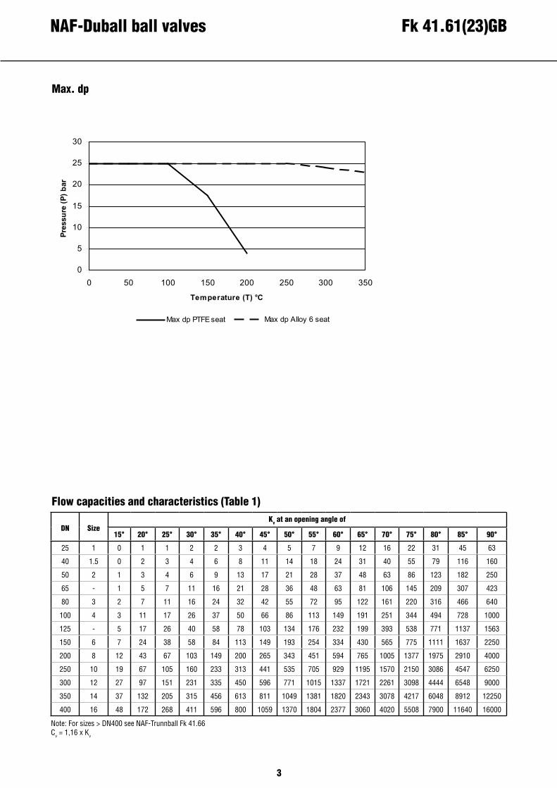
Working pressure, differential pressure and temperatureThe maximum working pressure and temperature in the body depends on pressure class according to respectively flange standards. For EN1092-1:2001 see the diagram. The differential pressure when the valve is closed is 25 bar, and the temperature dependence is shown in the dia-gram on page 3.The stem gland with EPDM O-ring can be used for temperatures up to 200°C.The standard design of stem gland with stuffing box and graphite packing and stem bushings in Stellite can be used for temperatures up to 350°C. For higher temperatures, consult NAF.
Max. Working Pressure PN Valves
0
10
20
30
40
50
0 50 100 150 200 250 300 350
Temperature (T) °C
Pressure
(P)b
ar
ANSI 300 bodyANSI 150 body
Max. Working Pressure ANSI valves
3
DN SizeKv at an opening angle of
15° 20° 25° 30° 35° 40° 45° 50° 55° 60° 65° 70° 75° 80° 85° 90°
25 1 0 1 1 2 2 3 4 5 7 9 12 16 22 31 45 63
40 1.5 0 2 3 4 6 8 11 14 18 24 31 40 55 79 116 160
50 2 1 3 4 6 9 13 17 21 28 37 48 63 86 123 182 250
65 - 1 5 7 11 16 21 28 36 48 63 81 106 145 209 307 423
80 3 2 7 11 16 24 32 42 55 72 95 122 161 220 316 466 640
100 4 3 11 17 26 37 50 66 86 113 149 191 251 344 494 728 1000
125 - 5 17 26 40 58 78 103 134 176 232 199 393 538 771 1137 1563
150 6 7 24 38 58 84 113 149 193 254 334 430 565 775 1111 1637 2250
200 8 12 43 67 103 149 200 265 343 451 594 765 1005 1377 1975 2910 4000
250 10 19 67 105 160 233 313 441 535 705 929 1195 1570 2150 3086 4547 6250
300 12 27 97 151 231 335 450 596 771 1015 1337 1721 2261 3098 4444 6548 9000
350 14 37 132 205 315 456 613 811 1049 1381 1820 2343 3078 4217 6048 8912 12250
400 16 48 172 268 411 596 800 1059 1370 1804 2377 3060 4020 5508 7900 11640 16000
Flow capacities and characteristics (Table 1)
Note: For sizes > DN400 see NAF-Trunnball Fk 41.66Cv = 1,16 x Kv
0
5
10
15
20
25
30
0 50 100 150 200 250 300 350
Temperature (T) °C
Pressu
re(P)b
ar
Max dp Alloy 6 seatMax dp PTFEseat
NAF-Duball ball valves Fk 41.61(23)GB
Max. dp
4
11
12
13
9 8 7 6 10 11
1 22 21 19 1 4 3
2 31 20 2
23 26 25 24 28 27
32
33
34
29
5
18
2 17 16 15 1
30 14
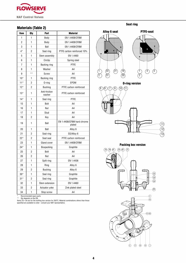
Materials (Table 2) Alloy 6 seat PTFE-seat
Seat ring
* Recommended spare parts ** Qty depends on the DN.Items 23—34 are for the stuffing box version for 350°C. Material combinations others than those specified are available to order - consult your NAF representative.
O-ring version
Item Qty Part Material
1 1 Body EN 1.4408/CF8M
2 1 Body EN 1.4408/CF8M
3 1 Ball EN 1.4408/CF8M
4* 2 Seat ring PTFE carbon reinforced 10%
5 1 Stem assembly EN 1.4460
6 1 Circlip Spring steel
7 1 Backing ring PTFE
8 1 Washer A4
9 ** Screw A4
10* 1 Backing ring PTFE
11* 2 O-ring EPDM
12* 2 Bushing PTFE carbon reinforced
13* 1 Anti-friction washer PTFE carbon reinforced
14* 1 Seal ring PTFE
15 1 Bolt A4
16 1 Nut A4
17 1 Stud A4
18 2 Key A4
19 1 Ball EN 1.4408/CF8M hard chrome plated
20 1 Ball Alloy 6
21 2 Seat ring SS/Alloy 6
22* 2 Seat seal PTFE carbon reinforced
23 1 Gland cover EN 1.4408/CF8M
24* 1 Boxpacking Graphite
25 2 Bolt A4
26 2 Nut A4
27 1 Split ring EN 1.4436
28 1 Ring Alloy 6
29 2 Bushing Alloy 6
30* 1 Seal ring Graphite
31* 2 Seal ring Graphite
32 1 Stem extension EN 1.4460
33 2 Actuator yoke Zink plated steel
34 1 Stop screw A4
Packing box version

5
Operating torque, Nm (Table 3)
DN
Differential pressure in bar
5 10 16 20 25
PTFE Alloy 6 PTFE Alloy 6 PTFE Alloy 6 PTFE Alloy 6 PTFE Alloy 6
25 12 15 16 20 19 23 22 30 25 35
40 16 20 23 28 30 36 35 42 40 50
50 20 25 30 36 40 48 48 60 60 70
65 30 36 50 60 75 85 85 105 110 130
80 55 65 90 110 130 160 160 200 200 240
100 95 115 160 190 250 280 300 350 350 450
125 180 210 320 390 480 550 530 690 680 850
150 300 350 530 620 750 950 920 1150 1100 1400
200 750 930 1350 1600 1900 2400 2380 2900 2900 3500
250 1500 1750 2500 3000 3600 4500 4400 5400 5200 6500
300 2400 3200 4000 5100 6000 7500 7200 9000 9000 11000
350 3800 4500 6400 8000 10000 12000 11500 14500 14500 18000
400 5500 7000 9700 12000 15000 18000 18000 22000 22000 26000
Operating torqueThe minimum design differential pressure for selecting the actuator is 5 bar. The specified torques in the table above are for clean media. For steam and with Stellite seat rings increases the required torque with factor 1.5. If the media contains solids, if it is a suspension, etc., consult NAF.
Sizing of control valvesWe have a user friendly valve calculation program which can be ordered through your NAF representative. The program is based on calculating formula according to the standards IEC 60534 and ISA S75.01.
NAF-Duball ball valves Fk 41.61(23)GB
6
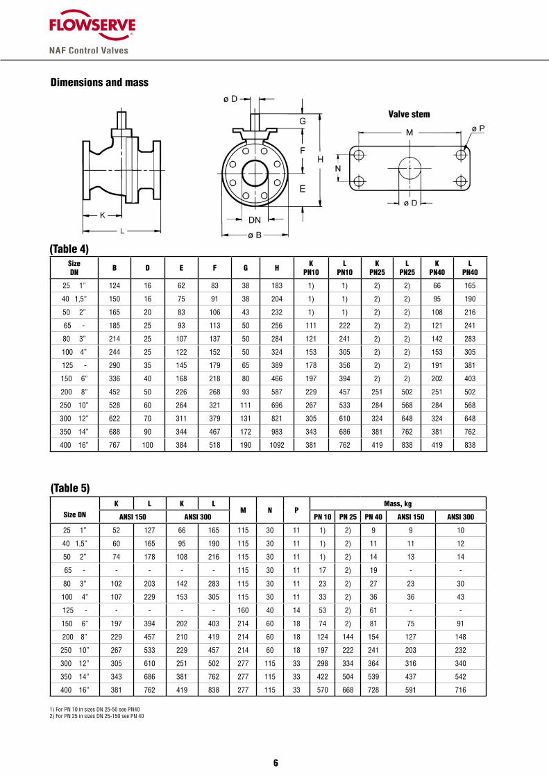
Valve stem
Dimensions and mass
1) For PN 10 in sizes DN 25-50 see PN402) For PN 25 in sizes DN 25-150 see PN 40
(Table 4)
(Table 5)
SizeDN B D E F G H K
PN10L
PN10K
PN25L
PN25K
PN40L
PN40
25 1” 124 16 62 83 38 183 1) 1) 2) 2) 66 165
40 1,5” 150 16 75 91 38 204 1) 1) 2) 2) 95 190
50 2” 165 20 83 106 43 232 1) 1) 2) 2) 108 216
65 - 185 25 93 113 50 256 111 222 2) 2) 121 241
80 3” 214 25 107 137 50 284 121 241 2) 2) 142 283
100 4” 244 25 122 152 50 324 153 305 2) 2) 153 305
125 - 290 35 145 179 65 389 178 356 2) 2) 191 381
150 6” 336 40 168 218 80 466 197 394 2) 2) 202 403
200 8” 452 50 226 268 93 587 229 457 251 502 251 502
250 10” 528 60 264 321 111 696 267 533 284 568 284 568
300 12” 622 70 311 379 131 821 305 610 324 648 324 648
350 14” 688 90 344 467 172 983 343 686 381 762 381 762
400 16” 767 100 384 518 190 1092 381 762 419 838 419 838
Size DNK L K L
M N PMass, kg
ANSI 150 ANSI 300 PN 10 PN 25 PN 40 ANSI 150 ANSI 300
25 1” 52 127 66 165 115 30 11 1) 2) 9 9 10
40 1,5” 60 165 95 190 115 30 11 1) 2) 11 11 12
50 2” 74 178 108 216 115 30 11 1) 2) 14 13 14
65 - - - - - 115 30 11 17 2) 19 - -
80 3” 102 203 142 283 115 30 11 23 2) 27 23 30
100 4” 107 229 153 305 115 30 11 33 2) 36 36 43
125 - - - - - 160 40 14 53 2) 61 - -
150 6” 197 394 202 403 214 60 18 74 2) 81 75 91
200 8” 229 457 210 419 214 60 18 124 144 154 127 148
250 10” 267 533 229 457 214 60 18 197 222 241 203 232
300 12” 305 610 251 502 277 115 33 298 334 364 316 340
350 14” 343 686 381 762 277 115 33 422 504 539 437 542
400 16” 381 762 419 838 277 115 33 570 668 728 591 716
7
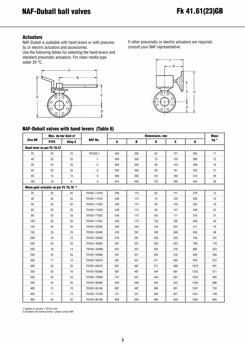
ActuatorsNAF-Duball is available with hand levers or with pneuma-tic or electric actuators and accessories.Use the following tables for selecting the hand levers and standard pneumatic actuators. For clean media type water 20 °C.
If other pneumatic or electric actuators are required, consult your NAF representative.
NAF-Duball valves with hand levers (Table 6)
1) Applies to actuator + PN 25 valve2) Available with locking device - please contact NAF
Size DNMax. dp bar Seat of
NAF No.Dimensions, mm Mass
kg 1)
PTFE Alloy 6 A B D E G
Hand lever as per Fk 70.51
25 25 25 791020-1 500 350 62 121 265 11
40 25 25 -1 500 350 75 129 286 13
50 25 25 -2 500 350 83 144 309 16
65 25 25 -3 500 350 93 161 335 21
80 15 13 -3 500 350 107 185 374 29
100 10 8 -3 615 450 122 200 404 38
Worm gear actuator as per Fk 70.76 2)
25 25 25 791051-11016 249 174 62 117 279 13
40 25 25 791051-11016 249 174 75 125 300 15
50 25 25 791051-11020 249 174 83 140 323 18
65 25 25 791051-11025 249 174 93 147 340 23
80 25 25 791051-11025 249 174 107 171 378 31
100 25 25 791051-11025 249 174 122 186 408 40
125 25 25 791051-22035 328 243 145 222 517 70
150 25 25 791051-33040 416 291 168 268 636 98
200 16 12 791051-33050 416 291 226 333 759 161
200 25 25 791051-43050 507 337 226 323 799 176
250 18 14 791051-43060 507 337 264 376 890 254
250 25 25 791051-53060 591 421 264 376 840 260
300 17 12 791051-55070 591 421 311 459 970 372
300 25 25 791051-65070 697 487 311 468 1079 401
350 20 16 791051-65090 697 487 344 591 1235 571
350 25 23 791051-75090 747 537 344 591 1235 585
350 25 25 791051-85090 848 593 344 552 1246 696
400 13 10 791051-65100 697 487 384 657 1341 735
400 17 14 791051-75100 747 537 384 657 1341 749
400 25 25 791051-85100 848 593 384 628 1362 860
NAF-Duball ball valves Fk 41.61(23)GB
8
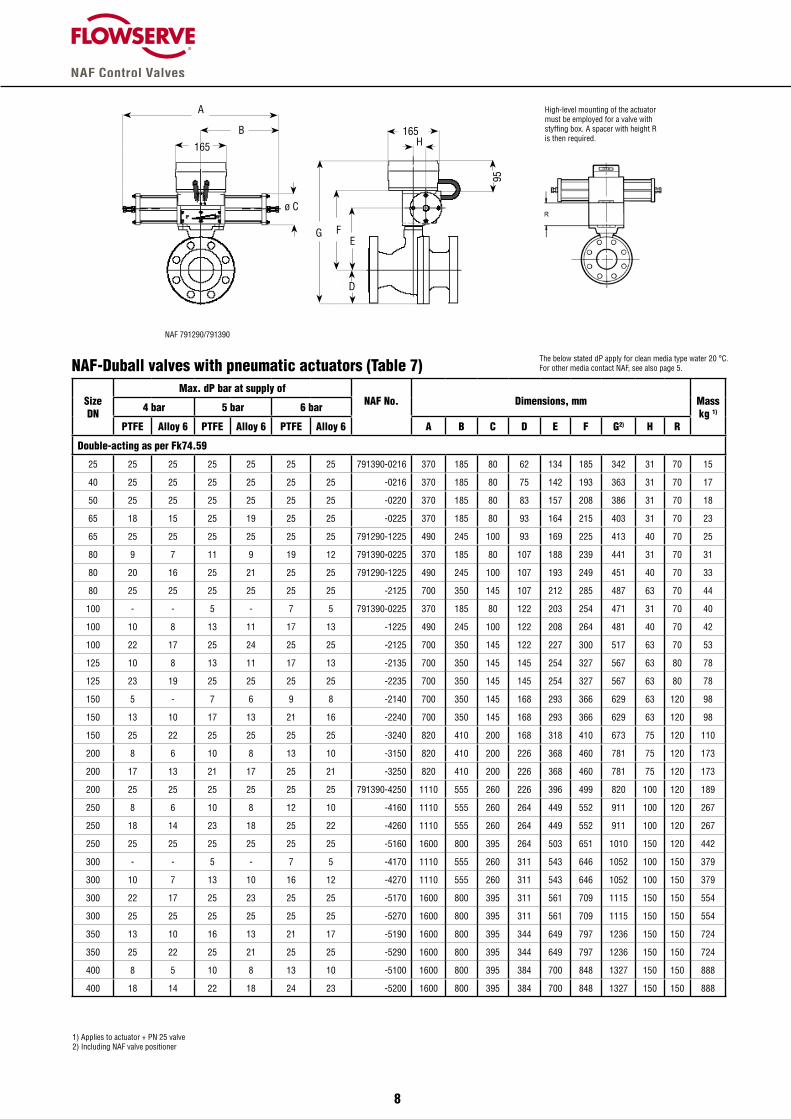
NAF 791290/791390
A
B
165
ø C
165H
G FE
95
D
High-level mounting of the actuator must be employed for a valve withstyffing box. A spacer with height Ris then required.
NAF-Duball valves with pneumatic actuators (Table 7)
1) Applies to actuator + PN 25 valve2) Including NAF valve positioner
The below stated dP apply for clean media type water 20 °C. For other media contact NAF, see also page 5.
SizeDN
Max. dP bar at supply ofNAF No. Dimensions, mm Mass
kg 1)4 bar 5 bar 6 bar
PTFE Alloy 6 PTFE Alloy 6 PTFE Alloy 6 A B C D E F G2) H R
Double-acting as per Fk74.59
25 25 25 25 25 25 25 791390-0216 370 185 80 62 134 185 342 31 70 15
40 25 25 25 25 25 25 -0216 370 185 80 75 142 193 363 31 70 17
50 25 25 25 25 25 25 -0220 370 185 80 83 157 208 386 31 70 18
65 18 15 25 19 25 25 -0225 370 185 80 93 164 215 403 31 70 23
65 25 25 25 25 25 25 791290-1225 490 245 100 93 169 225 413 40 70 25
80 9 7 11 9 19 12 791390-0225 370 185 80 107 188 239 441 31 70 31
80 20 16 25 21 25 25 791290-1225 490 245 100 107 193 249 451 40 70 33
80 25 25 25 25 25 25 -2125 700 350 145 107 212 285 487 63 70 44
100 - - 5 - 7 5 791390-0225 370 185 80 122 203 254 471 31 70 40
100 10 8 13 11 17 13 -1225 490 245 100 122 208 264 481 40 70 42
100 22 17 25 24 25 25 -2125 700 350 145 122 227 300 517 63 70 53
125 10 8 13 11 17 13 -2135 700 350 145 145 254 327 567 63 80 78
125 23 19 25 25 25 25 -2235 700 350 145 145 254 327 567 63 80 78
150 5 - 7 6 9 8 -2140 700 350 145 168 293 366 629 63 120 98
150 13 10 17 13 21 16 -2240 700 350 145 168 293 366 629 63 120 98
150 25 22 25 25 25 25 -3240 820 410 200 168 318 410 673 75 120 110
200 8 6 10 8 13 10 -3150 820 410 200 226 368 460 781 75 120 173
200 17 13 21 17 25 21 -3250 820 410 200 226 368 460 781 75 120 173
200 25 25 25 25 25 25 791390-4250 1110 555 260 226 396 499 820 100 120 189
250 8 6 10 8 12 10 -4160 1110 555 260 264 449 552 911 100 120 267
250 18 14 23 18 25 22 -4260 1110 555 260 264 449 552 911 100 120 267
250 25 25 25 25 25 25 -5160 1600 800 395 264 503 651 1010 150 120 442
300 - - 5 - 7 5 -4170 1110 555 260 311 543 646 1052 100 150 379
300 10 7 13 10 16 12 -4270 1110 555 260 311 543 646 1052 100 150 379
300 22 17 25 23 25 25 -5170 1600 800 395 311 561 709 1115 150 150 554
300 25 25 25 25 25 25 -5270 1600 800 395 311 561 709 1115 150 150 554
350 13 10 16 13 21 17 -5190 1600 800 395 344 649 797 1236 150 150 724
350 25 22 25 21 25 25 -5290 1600 800 395 344 649 797 1236 150 150 724
400 8 5 10 8 13 10 -5100 1600 800 395 384 700 848 1327 150 150 888
400 18 14 22 18 24 23 -5200 1600 800 395 384 700 848 1327 150 150 888

9
G FE
165H
95
Ø C
B
A
165
NAF791292/791392
D
The below stated dP apply for clean media type water 20 °C. For other media contact NAF, see also page 5.
1) Applies to actuator + PN 25 valve
(Table 8a)
SizeDN
Max dP bar at supply ofNAF No. Dimensions, mm Mass
kg 1)4 bar 5 bar 6 bar
PTFE Alloy 6 PTFE Alloy 6 PTFE Alloy 6 A B C D E F G2) H R
Single-acting, spring to close as per Fk 74.59
25 25 20 25 25 25 25 791392-0216 455 270 80 62 134 185 342 31 70 14
40 16 12 25 22 25 25 -0216 455 270 80 75 142 193 363 31 70 16
40 25 25 25 25 25 25 791292-1216 635 390 100 75 147 203 373 40 70 20
50 10 8 18 15 25 20 791392-0220 455 270 80 83 157 208 386 31 70 19
50 25 25 25 25 25 25 791292-1220 635 390 100 83 162 218 396 40 70 23
65 16 13 25 25 25 25 -1225 635 390 100 93 169 225 413 40 70 28
80 8 6 15 12 19 12 -1225 635 390 100 107 193 249 451 40 70 36
80 25 25 25 25 25 25 -2225 890 540 145 107 212 285 487 63 70 50
100 - - 8 6 10 6 -1225 635 390 100 122 208 264 481 40 70 45
100 20 16 25 25 25 25 -2225 890 540 145 122 227 300 517 63 70 59
125 9 7 17 14 22 14 -2235 890 540 145 145 254 327 567 63 80 84
125 25 25 25 25 25 25 -3235 1050 640 200 145 285 377 617 75 80 104
150 5 - 10 8 12 8 -2240 890 540 145 168 293 366 629 63 120 104
150 25 20 25 25 25 25 -3240 1050 640 200 168 318 410 673 75 120 124
150 25 25 25 25 25 25 791392-4240 1520 965 260 168 346 449 712 100 120 181
200 8 6 13 8 17 8 791292-3250 1050 640 200 226 368 460 781 75 120 187
200 14 11 25 22 25 22 791392-4250 1520 965 260 226 396 499 820 100 120 244
250 6 5 14 10 17 10 -4260 1520 965 260 264 449 552 911 100 120 322
250 25 25 25 25 25 25 -5260 2210 1370 395 264 503 651 1010 150 120 687
300 - - 7 5 9 5 -4270 1520 965 260 311 543 646 1052 100 150 434
300 25 19 25 25 25 25 -5270 2210 1370 395 311 561 709 1115 150 150 800
350 14 11 22 18 25 18 -5290 2210 1370 395 344 649 797 1236 150 150 969
400 9 6 14 11 17 11 -5200 2210 1370 395 384 700 848 1327 150 150 1133
2) Including NAF valve positioner
NAF-Duball ball valves Fk 41.61(23)GB
10
165
G FE
H165
A
Ø C
B
95
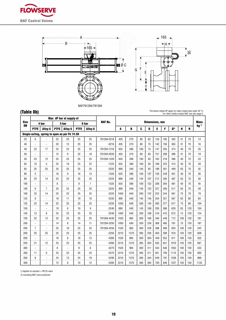
NAF791294/791394
D
SizeDN
Max dP bar at supply ofNAF No. Dimensions, mm Mass
kg 1)4 bar 5 bar 6 bar
PTFE Alloy 6 PTFE Alloy 6 PTFE Alloy 6 A B C D E F G2) H R
Single-acting, spring to open as per Fk 74.59
25 6 - 25 25 25 25 791394-0216 455 270 80 62 134 185 342 31 70 14
40 - - 20 15 25 25 -0216 455 270 80 75 142 193 363 31 70 16
40 25 17 25 25 25 25 791294-1216 635 390 100 75 147 203 373 40 70 20
50 - - 12 9 22 18 791394-0220 455 270 80 83 157 208 386 31 70 19
50 25 12 25 25 25 25 791294-1220 635 390 100 83 162 218 396 40 70 23
65 10 5 25 19 25 22 -1225 635 390 100 93 169 225 413 40 70 28
65 25 25 25 25 25 25 -2225 890 540 145 93 188 261 449 63 70 42
80 5 - 16 9 16 13 -1225 635 390 100 107 193 249 451 40 70 36
80 25 14 25 25 25 25 -2225 890 540 145 107 212 285 487 63 70 50
100 - - 8 - 8 7 -1225 635 390 100 122 208 264 481 40 70 45
100 8 7 25 22 25 25 -2225 890 540 145 122 227 300 517 63 70 59
100 25 14 25 25 25 25 -3225 1050 640 200 122 252 344 561 75 70 79
125 6 - 19 11 19 16 -2235 890 540 145 145 254 327 567 63 80 84
125 23 14 25 25 25 25 -3235 1050 640 200 145 285 377 617 75 80 104
150 - - 10 6 10 9 -2240 890 540 145 168 293 366 629 63 120 104
150 13 8 25 23 25 25 -3240 1050 640 200 168 318 410 673 75 120 124
150 22 12 25 25 25 25 791394-4240 1520 965 260 168 346 449 712 100 120 181
200 - - 14 8 14 11 791294-3250 1050 640 200 226 368 460 781 75 120 187
200 7 - 25 16 25 25 791394-4250 1520 965 260 226 396 499 820 100 120 242
200 25 25 25 25 25 25 -5250 2210 1370 395 226 450 598 919 150 120 609
250 - - 16 8 16 12 -4260 1520 965 260 264 449 552 911 100 120 322
250 21 12 25 25 25 25 -5260 2210 1370 395 264 503 651 1010 150 120 687
300 - - 8 - 8 6 -4270 1520 965 260 311 543 646 1052 100 150 433
300 11 6 25 22 25 25 -5270 2210 1370 395 311 561 709 1115 150 150 800
350 6 - 24 13 24 19 -5290 2210 1370 395 344 649 797 1236 150 150 969
400 - - 15 8 15 12 -5200 2210 1370 395 384 700 848 1327 150 150 1133
The below stated dP apply for clean media type water 20 °C. For other media contact NAF, see also page 5.(Table 8b)
1) Applies to actuator + PN 25 valve
2) Including NAF valve positioner
11
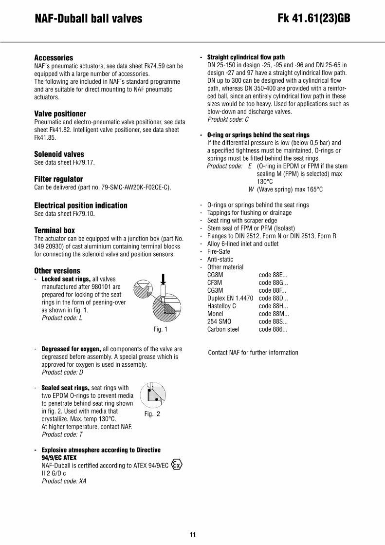
Fig. 1
Fig. 2
AccessoriesNAF´s pneumatic actuators, see data sheet Fk74.59 can be equipped with a large number of accessories.The following are included in NAF´s standard programme and are suitable for direct mounting to NAF pneumatic actuators.
Valve positionerPneumatic and electro-pneumatic valve positioner, see data sheet Fk41.82. Intelligent valve positioner, see data sheet Fk41.85.
Solenoid valvesSee data sheet Fk79.17.
Filter regulatorCan be delivered (part no. 79-SMC-AW20K-F02CE-C).
Electrical position indicationSee data sheet Fk79.10.
Terminal boxThe actuator can be equipped with a junction box (part No. 349 20930) of cast aluminium containing terminal blocks for connecting the solenoid valve and position sensors.
Other versions- Locked seat rings, all valves
manufactured after 980101 are prepared for locking of the seat rings in the form of peening-over as shown in fig. 1.
Product code: L
- Degreased for oxygen, all components of the valve are degreased before assembly. A special grease which is approved for oxygen is used in assembly. Product code: D
- Sealed seat rings, seat rings with two EPDM O-rings to prevent media to penetrate behind seat ring shown in fig. 2. Used with media that crystallize. Max. temp 130°C.
At higher temperature, contact NAF. Product code: T
- Explosive atmosphere according to Directive 94/9/EC ATEX
NAF-Duball is certified according to ATEX 94/9/EC II 2 G/D c
Product code: XA
NAF-Duball ball valves Fk 41.61(23)GB
- Straight cylindrical flow path DN 25-150 in design -25, -95 and -96 and DN 25-65 in
design -27 and 97 have a straight cylindrical flow path. DN up to 300 can be designed with a cylindrical flow path, whereas DN 350-400 are provided with a reinfor-ced ball, since an entirely cylindrical flow path in these sizes would be too heavy. Used for applications such as blow-down and discharge valves.
Produkt code: C
- O-ring or springs behind the seat rings If the differential pressure is low (below 0,5 bar) and
a specified tightness must be maintained, O-rings or springs must be fitted behind the seat rings.
Product code: E (O-ring in EPDM or FPM if the stem sealing M (FPM) is selected) max 130°C
W (Wave spring) max 165°C
- O-rings or springs behind the seat rings- Tappings for flushing or drainage- Seat ring with scraper edge- Stem seal of FPM or PFM (Isolast) - Flanges to DIN 2512, Form N or DIN 2513, Form R- Alloy 6-lined inlet and outlet- Fire-Safe- Anti-static- Other material CG8M code 88E... CF3M code 88G... CG3M code 88F... Duplex EN 1.4470 code 88D... Hastelloy C code 88H... Monel code 88M... 254 SMO code 88S... Carbon steel code 886...
Contact NAF for further information

12
NAF AB SE-581 87 LinköpingSweden
Telephone +46 13 31 61 00 Facsimile +46 13 13 60 54 e-mail [email protected]: www.naf.se
We reserve the right to design modifications without prior notice
ISO 9001 Certified
Product code NAF-Duball valvesExample:
88 8 6 9 7 - 0150 Code 1 2 3 4 5 6
1. Valve type 88 Ball valve 2. Material (Body) 1)
8 1.4408 / CF8M
3. Pressure rating 2 PN 10 (DN 65 — 400)2)
4 ANSI Class 150 (Size 1” — 16”) 5 PN 25 (DN 200 — 400)2)
6 PN 40 (DN 25 — 400) 7 ANSI Class 300 (Size 1” — 16”)
4. Stem seal 2 Graphite stuffing box, up to 350°C3)
9 EPDM O-ring, up to 200°C
5. Seals Ball Seat ring 5 EN1.4408 / CF8M Alloy 6 hard chromium-plated 6 EN1.4408 / CF8M PTFE, carbon reinforced 7 Alloy 6 Alloy 6
6. Size EN version ANSI version DN Size 0025 25 0001 1” 0040 40 01.5 1.5” 0050 50 0002 2” 00654) 65 - - 0080 80 0003 3” 0100 100 0004 4” 01254) 125 - - 0150 150 0006 6” 0200 200 0008 8” 0250 250 0010 10” 0300 300 0012 12” 0350 350 0014 14” 0400 400 0016 16” 1) Other materials see page 11.
2) Size 25—50 has the same flange dimensions in PN 10, 16, 25 and 40. Choose PN 40 for these sizes.
Size 65—150 has the same flange dimensions in PN 25 and 40. Choose PN 40 for these sizes.
3) Suffing box version includes stem extension and actuator yoke.
4) DN 65 and 125 contact NAF