NACAA copy FIL - NASA · FORCES AND MOMENTS ON TWO DELTA WINGS OF . ... v velocity of test medium,...
29
SECURI1 INJFRNA.ATKDM CONFIDENTIAL Copy RM L53J26a NACAA FIL copy RESEARCH MEMORANDUM SOME MEASUREMENTS AT SUBSONIC SPEEDS OF THE AERODYNAMIC Cv FORCES AND MOMENTS ON TWO DELTA WINGS OF . ASPECT RATIOS 2 AND 4 OSCILLATING ABOUT THE MIDCHORD By Sumner A. Leadbetter and Sherman A. Clevenson F Langley Aeronautical Laboratory Langley Field, Va. Cq - CLASSIFIED DOCUMENT ?—j rr This material contains information affecting the National Defense of the United States within the mesg of the espionage laws, Title 18, U.S.C., Secs. 793 and 794, the transmission or revelation of which )ny manner to on unauthorized person Is prohibited by law. NATIONAL ADVISORY COMMIThi FOR AERONAUTICS WASHINGTON December 10, 1953 CQPFI DEN hAL https://ntrs.nasa.gov/search.jsp?R=19930087943 2018-05-29T02:03:24+00:00Z
Transcript of NACAA copy FIL - NASA · FORCES AND MOMENTS ON TWO DELTA WINGS OF . ... v velocity of test medium,...

SECURI1 INJFRNA.ATKDM
CONFIDENTIAL Copy RM L53J26a
NACAA FIL copy
RESEARCH MEMORANDUM
SOME MEASUREMENTS AT SUBSONIC SPEEDS OF THE AERODYNAMIC Cv
FORCES AND MOMENTS ON TWO DELTA WINGS OF .
ASPECT RATIOS 2 AND 4 OSCILLATING
ABOUT THE MIDCHORD
By Sumner A. Leadbetter and Sherman A. Clevenson F Langley Aeronautical Laboratory
Langley Field, Va.Cq-
CLASSIFIED DOCUMENT ?—j rr
This material contains information affecting the National Defense of the United States within the mesg of the espionage laws, Title 18, U.S.C., Secs. 793 and 794, the transmission or revelation of which )ny manner to on unauthorized person Is prohibited by law.
NATIONAL ADVISORY COMMIThi FOR AERONAUTICS
WASHINGTON December 10, 1953
CQPFI DEN hAL
https://ntrs.nasa.gov/search.jsp?R=19930087943 2018-05-29T02:03:24+00:00Z

NACA RN L73J26a CONFIDENTIAL
NATIONAL ADVISORY COMMITTEE FOR AERONAUTICS
RESEARCH MEMORANDUM
SOME MEASUREMENTS AT SUBSONIC SPEEDS OF THE AERODYNAMIC
FORCES AND MOMENTS ON TWO DELTA WINGS OF
ASPECT RATIOS 2 AND 4 OSCILLATING
ABOUT THE MIDCHORD
By Sumner A. Lead.better and Sherman A. Clevenson
SUMMARY
Air forces and moments acting on delta wings of aspect ratios 2 and 14 oscillating about the root midchord position have been measured and are reported herein. The Mach number and Reynolds number ranges
covered were from 0.19 to 0.81 and 0.90 x 1o 6 to 4.40 x 10⁶ , respectively, and the reduced-frequency range was from 0.08 to 0.81. Comparisons of the measured values were made with the results of the analysis of Lawrence and Gerber and, in general, reasonably good agreement was obtained. The measured values for the delta wing with aspect ratio of 2 were also com-pared with the results of "vanishing-aspect-ratio" theory and good agree-ment was shown for the lift coefficients.
INTRODUCTION
The experimental measurement of oscillating air forces is receiving increased attention because of the importance of these forces in flutter and related problems and because the experimental values are urgently needed to. assess existing theoretical work. Despite the importance of this problem there exists only a limited amount of data for restricted ranges of aspect ratio, Mach number, and Reynolds number (see, for exam-ple, ref. 1).
There exists only a rather meager amount of theoretical work on oscillating air forces on delta wings. For incompressible flow, for instance, coefficients have been tabulated by Lawrence and Gerber for delta wings of low aspect ratio (ref. 2) and the "vanishing-aspect-ratio" theory of reference 3 has been developed for delta wings of very low
CONFIDENTIAL

2 CONFIDENTIAL NACA RM L53J26a
aspect ratio. No experimental work on oscillating air forces on delta wings has been reported that can be used to appraise the theoretical results.
This paper presents some experimental measurements of oscillating air force and moment coefficients as well as their respective phase angles as determined from tests of two delta wings of aspect ratios 2 and 4 which were oscillated about the root midchord position. The coef-ficients were determined for a Mach number and Reynolds number range
of 0.19 to 0.81 and 0.90 x 10⁶ to 4.40 x 10⁶, respectively. The reduced frequency ranged from 0.08 to 0.81. The measurements were made In the Langley 2- by 4-foot flutter research tunnel using a resonant oscilla-tion technique used previously in the tests of rectangular wings of low aspect ratio reported in reference 4 • The results of the experimental investigation discussed in this paper are compared with the theoretical results of reference 2 and with those of the vanishing-aspect-ratio theory (ref. 3).
SYMBOLS
A aspect ratio
C root chord of wing, ft
k reduced-frequency parameter, u/2v
1 1al absolute value of lift coefficient per unit amplitude
of oscillation,
lift coefficient in phase with angular displacement,I l
çj (O5 (I)
lift coefficient in phase with angular velocity, 11alsino
La oscillating lift vector, positive when acting
upward, Iie180)
ILMIabsolute value of lift vector
M Mach number
CONFIDENTIAL

NACA 1RM L53J26a CONFIDENTIAL 3
Ia.Iabsolute value of moment coefficient per unit amplitude
of oscillation, a.
in1 moment coefficient in phase with angular displacement, ma.tcos ®
in2 moment coefficient out of phase with angular displacement, I ma.I s in ®
Ma. oscillating moment vector referred to axis of rotation, root midchord, positive in direction of leading edge
I up, Ma.Ie (alt, 180
IM absolute magnitude of moment vector
q dynamic pressure, lb/sq ft
R Reynolds number based on root chord of wing
S area of wing, sq ft
t time, sec
v velocity of test medium, fps
a, angle of incidence vector, positive when leading edge up, radians
jal absolute magnitude of angle of incidence, radians
phase angle that the moment vector leads the incidence
vector, 1800 - tan . m1
phase angle that the lift vector leads the incidence
vector, tan-12 -
P density, slugs/cu ft
circular frequency of pitching oscillation of wing, radians/sec
CONFIDENTIAL

11. CONFIDENTIAL NACA BM L73J26a
circular frequency of first natural wing bending oscillations, radians/sec
vac circular frequency of pitching oscillations in a near vacuum, radians/sec
APPARATUS AND METHOD
Tunnel. - The Langley 2- by 4-foot flutter research tunnel which permits testing at various pressures was used for the tests reported herein. All tests were made in air. Further description of this tunnel can be found in reference 14
Wing models, - The semispan wing models were of thick-skin balsa construction covered with glass cloth and had an NACA 65A010 airfoil section. Both models had a 12-inch semispan. The model with aspect ratio of 11 had a root chord of 12 inches and the A = 2 model had a root chord of 24 inches. These wings were designed to have high nat-ural frequencies in order to minimize elastic deformation and result-ant correction to the measured forces. The first natural cantilever bending frequency was 198 cycles per second for the A = 4 wing and 171 cycles per second for the A = 2 wing.
Oscillating mechanism. - The oscillating mechanism is the one described in considerable detail in reference 4. Stated briefly, the oscillating mechanism may be considered as a simple torsional vibratory system consisting of a torsion spring which is fixed at one end, a hol-low steel shaft which is supported by bearings, and the semispan wing. (See fig. 1.) The mechanism was oscillated at its natural frequency by applying a harmonically varying torque with an electromagnetic shaker. The amplitude of oscillation was ±20 . Four different torsion springs were used to cover a range of frequency of oscillation. The pitching natural frequencies in a near vacuum uac for the two wings were as
follows:
Torsion springvac (radians/sec) for -
A=2wing A=wing
1 20X2it 21X2it
2 29
3 38
4 48 Not tested
CONFIDENTIAL

NACA RM L53J26a CONFIDENTIAL 5
Instrumentation and.calibration.- The instrumentation is the same as that described in reference if. The lift was obtained from strain-gage beams and its phase angle was determined with the aid of an elec-tronic counter chronograph. The damping moment (out of phase) was obtained from a decrement trace of the wing position on a recording oscillograph. The in-phase moment was determined from the difference in resonant fre-quency between the model oscillating in a vacuum and in air at the test Mach number as measured with the electronic counter chronograph. The phase angle 0 between lift vector and the angle of incidence was also measured with an electronic counter chronograph. The calibrations of the balances and angular displacement were essentially the same as those in reference Ii. with the exception of the wing-position determination. For these delta wings, the fine chord.wise line used in the photographic technique was placed on the root, plate instead of on the wing tip.
Data reduction. - The lift forces as determined from the strain-gage balances were corrected for an inertia component resulting from wing-bending deformation. These corrections were small; therefore, a simple approximate method developed in appendix A of reference if was used. The inclusion of this correction leads to the following factor which when multiplied by the measured lift gives the actual applied lift: for spring 1, 0.996 and 0.997; for spring 2, 0.992 and 0.992; for spring 3, O.984 and 0.986; and for spring if, 0.975 for the A = 2 and A = 4 delta wings, respectively.
Methods for determining the in-phase and the out-of-phase components of the moment coefficients from the measured data are discussed in detail in references 4 and 5, as are some of the accuracies involved in this type of measurement. The phase angle e between the moment vector and the angle of incidence was obtained from the ratio of the measured components.
RESULTS
The experimental data obtained from the lifts, moments, and their respective phase angles are given in tables I to IV for the A = 2 and A = 4 wings. Also given in these tables are the corresponding Mach number, Reynolds number, and reduced frequencies. The in-phase moments were omitted in tables III and IV for the A.= 2 wing since the fre-quency shift was too small to obtain satisfactory values. The theoret-ical values are given in table V. To show trends and comparisons, the experimental and theoretical values are shown in figures 2 to 12. A small part of the A = 2 wing data has been previously shown in reference 6.
CONFIDENTIAL

6 CONFIDENTIAL NACA RM L73J26a
DISCUSSION
Tunnel-Wall Effects
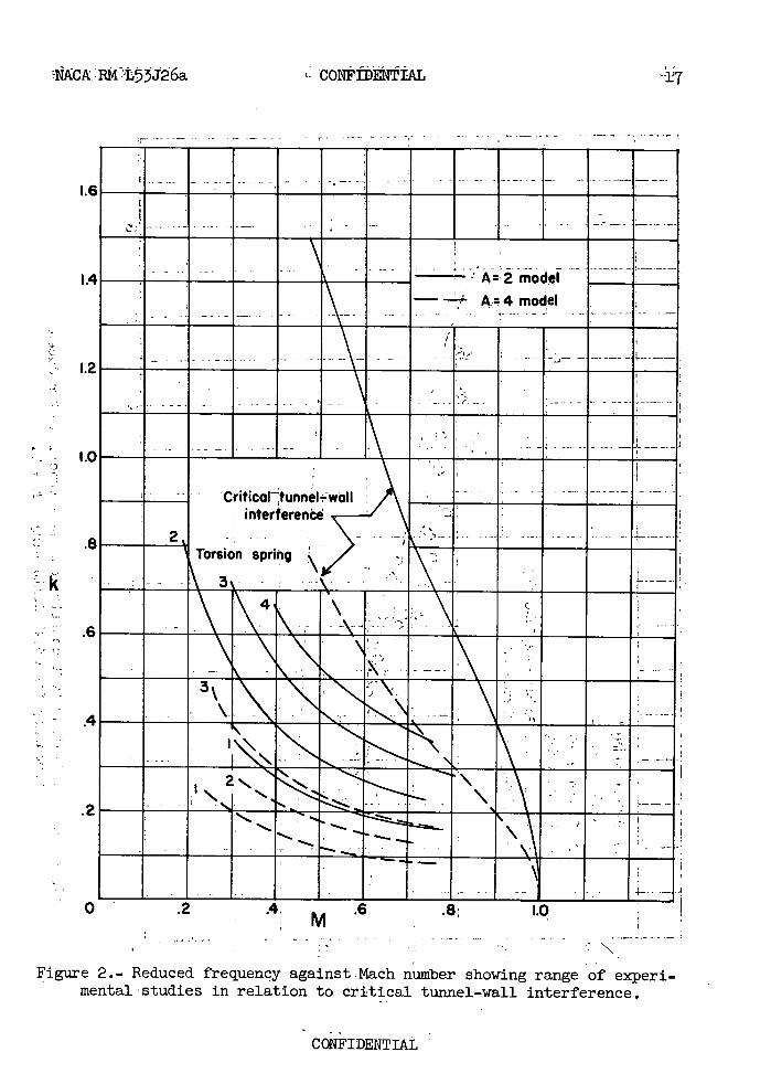
Oscillatory coefficients obtained from wind-tunnel measurements may be influenced by tunnel-wall interference which may take the form of a resonance phenomenon (see ref. 7) . Thus, before presenting and discussing the measured lift, moments, and phase angles, the range of these experimental studies in relation to critical tunnel-wall inter-ference is stated. In order to show the proximity of the data to the region of critical tunnel-wall interference based on two-dimensional flow, a plot of k against M for the various torsion springs is shown with curves of critical tunnel-wall effects In figure 2. The curves representing the experimental data are well away from their cor-responding curve of critical wall interference and, thus, the tunnel-wall effects are expected to be small.
Effects of Mach Number and Reynolds Number
Since the testing technique used did not readily permit either M or B to be held constant while varying the other parameters, consid-erable cross-plotting would have been necessary to obtain an indication of any effect. It was found in reference Ii. that, for the ranges of speed and frequencies covered, the overall effects of M and R did not appear to be of first order and perhaps were within the accuracy of the experimentation. For this Investigation a sufficient quantity of data was not obtained to attempt to Isolate the effects of M and R; however, a few data points which could be compared did not show sig-nificant effects.
Comparisons of the Measured Values for A = 2 Wing With Theory
The oscillating lift coefficient IlaJ for the A = 2 wing are shown as a. function of reduced frequency In figure 3. Also shown are the coefficients calculated by the method of Lawrence and Gerber (ref. 2) and the results of vanishing-aspect-ratio theory (ref. 3). Over most of the range of k . investigated, the results of the vanishing-aspect- ratio theory generally showed good agreement with the experimental results. The coefficients of Lawrence and Gerber are found to be con-siderably lower than the experimentally determined coefficients. The phase angle by which the oscillating lift force leads the angular dis-placement of the wing is shown in figure Ii-. As indicated in this figure, the results of Lawrence and Gerber give phase angles slightly above the experimentally determined values, and the results of the vanishing-aspect-ratio theory give results slightly above those of Lawrence and
CONFIDENTIAL

NACA EM L73J26a CONFIDENTIAL 7
Gerber. The analytical lift phase angles as determined from both methods are considered to be in fair agreement with the experimental phase angles.
Inasmuch as the aerodynamic moment data were obtained experimentally in component form, it is appropriate to compare these values with the analytical values of the components of the aerodynamic moment. The damping moment coefficients (out-of-phase component) for the A = 2 wing are shown as a function of reduced frequency in figure 5 . It may be seen that the measured coefficients are in good agreement with the theoretical coefficients of Lawrence and Gerber, but they are lower than those pre-dicted by the vanishing-aspect-ratio theory by approximately a factor of 3.
In figure 6, a comparison of the measured in-phase moment coefficient with those given by theory may be made. The coefficients of Lawrence and Gerber and the coefficients of the vanishing-aspect-ratio theory are shown. The results of the theory of Lawrence and Gerber underestimate the coef-ficients in the range of k covered whereas the results of the vanishing-aspect-ratio theory are higher than the experimental coefficients.
As in reference 14 , the phase angle between the moment vector and the angular position vector was obtained from the ratio of the out-of-phase (damping) and in-phase moment coefficients and is shown in figure 7. The measured phase angles are in fair agreement with those of vanishing-aspect-ratio theory while the theory of Lawrence and Gerber has phase angles whose magnitudes are slightly smaller than the experimental values.
Comparison of the Measured Values for A = Ii. Wing With Theory
The A = 4 delta-wing coefficients and phase angles are presented in figures 8 to 12. Since the root chord of this wing is one-half the root chord of the A = 2 wing, and since the frequency of oscillation and air velocity are essentially the same, the reduced-frequency range is less by a factor of 2. The oscillating lift coefficients for the A = 4 delta wing are shown as a function of reduced frequency in fig-ure 8. Also shown for comparison are the coefficients of Lawrence and Gerber for an A = 4 delta wing. The results of the vanishing-aspect-ratio theory are not shown as it is felt that A = i is too large to be considered a vanishing aspect ratio. Over mc3t of the reduced-frequency range covered, good agreement is shown between the experi-mental and theoretical coefficients.
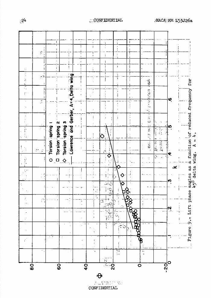
The phase angles by which the oscillating lift force leads the angu-lar displacement of the wing are shown in figure 9 as a function of k. Good agreement with the theoretical phase angles of Lawrence and Gerber is shown for the larger part of the range covered in these tests. At the lower values of Ic, the experimental phase angles tend to become negative indicating that the lift is lagging the angular displacement.
CONFIDENTIAL

8 CONFIDENTIAL NACA RM L53J26a
Figure 10 shows the damping moment coefficient as a function of reduced frequency. It may be seen that the experimental coefficients are lower than the theoretical coefficients.
Referring to figure 11, a comparison of the measured moment coef-ficients in phase with angular displacement with those given by Lawrence and Gerber may be made. The large scatter in the experimental data may be attributed to the technique of obtaining the coefficients. The moment is determined basically from a shift in resonant frequencies from the frequency in a vacuum to the frequency at aparticular test point. This frequency shift is usually small compared with the resonant frequency of the system. The process of taking small differences of relatively large numbers tends to introduce considerable scatter in the data.
The phase angle by which the resultant moment leads the angular position is shown in figure 12. As maybe seen, the phase angles pre-dicted by the theory of Lawrence and Gerber are considerably smaller than the experimentally determined magnitudes of the moment phase angles.
Comparison of A = 2 With A = 4 Data
A comparison of the A = 2 data may be made with the A = 4 data by comparing figures 3 to 7 with figures 8 to 12. Figures 3 and 8 show the lift coefficients as functions of reduced frequency. Although the results of Lawrence and Gerber indicate the lift coefficients for the A = 4 delta to be roughly 35 percent greater than the lift coefficients for the A = 2 delta wing, the experimentally determined coefficients show the A = i- wing to have only slightly higher lift coefficients than the A = 2 wing at the lower values of reduced frequencies. For values of reduced frequencies greater than 0.46, forces and phase angles were not obtained for the A = 4 wing, and thus are not compared with the A = 2 wing in this range.
A comparison of the lift phase angles (figs. 4 and 9) as determined by Lawrence and Gerber show the A = 4 phase angles to be slightly less than the A = 2 phase angles. Correspondingly, the experimental phase angles for A = l. were somewhat smaller than the A = 2 phase angles.
A comparison of the damping moment coefficients for these two delta wings (figs. 5 and 10) indicated that both the analytical and experimental coefficients decrease as the aspect ratio decreases from i-i- to 2. A com-parison of the in-phase moment coefficients indicate that, analytically, the in-phase moment coefficient increases from A = 24 to A = 2, whereas the experimental moment coefficients, based on average data shown in fig-ures 6 and 11, tend to decrease from A = 4 to A = 2. The phase angles of the moment coefficients are seen to be of about the same magnitude for
CONFIDENTIAL

NACA RM L5J26a CONFIDENTIAL 9
the two delta wings, whereas the results of Lawrence and Gerber indicate an increase in magnitude for the A = 1. to the A = 2 wing (figs. 7 and 12).
CONCLUDING REMARKS
The oscillating air forces and moments acting on delta wings of aspect ratios 2 and 4 oscillating about the root midchord position have been measured and are reported herein. The Mach number and Reynolds
number ranges covered were from 0.19 to 0.81 and 0.90 x 10 6 to 4.40 x 10⁶, respectively, and the reduced-frequency range was from 0.08 to 0.81. Comparisons of the measured values were made with the results of the analysis of Lawrence and Gerber and, in general, reasonably good agree-ment was obtained. The measured values for the delta wing with aspect ratio of 2 were also compared with the results of "vanishing-aspect-ratio " theory and good agreement was shown for the lift coefficients.
Langley Aeronautical Laboratory, National Advisory Committee for Aeronautics,
Langley Field, Va., October 13, 1953.
CONFIDENTIAL

10 CONFIDENTIAL NACA RN L53J26a
REFERENCES
1. Williams, J.: Aircraft Flutter. R. & M. No. 2492, British A.R.C., 1948.
2. Lawrence, H. R., and Gerber, E. H.: The Aerodynamic Forces on Low Aspect Ratio Wings Oscillating in an Incompressible Flow. Jour. Aero.Sci., vol. 19, no. 11, Nov. 1952, PP. 769-781. (Errata issued, vol. 20, no. 1, Apr. 1953, p. 296.)
3. Garrick, I. E.: Some Research on High-Speed Flutter. Royal Aero. Soc., 1952, pp. 419-446. (Presented at Third International Joint Conference of the R.A.S.-I.A.S., Brighton, England, Sept. 314, 1951.)
LI. . Widmayer, Edward, Jr., Clevenson, Sherman A., and Leadbetter, Sumner A.: Some Measurements of Aerodynamic Forces and Moments at Subsonic Speeds on a Rectangular Wing of Aspect Ratio 2 Oscillating About the Midchord. NACA RN L53F19, 1953.
5. Clevenson, S. A., and Widmayer, E., Jr.: Preliminary Experiments on Forces and Moments of an Oscillating Wing at High-Subsonic Speeds. NACA EM L9K28a, 1950.
6. Clevenson, Sherman A., Leadbetter, Sumner A., and Tuovila, Weimer J.: Discussion of Three-Dimensional Oscillating Air Forces Based on Wind-Tunnel Measurement. NACA EM L53E18a, 1953.
7. Runyan, Harry L., and Watkins, Charles E.: Considerations on the Effect of Wind-Tunnel Walls on Oscillating Air Forces for Two-Dimensional Subsonic Compressible Flow. NACA TN 2552, 1951.
CONFIDENTIAL

NACA RM L53J26a CONFIDENTIAL 11
TABLE I. - EXPERIMENTAL DATA FOR TORSION SPRING 1
k p M R 110,1 ® -m1 '2
For A = 2 wing
0.16 100 x io-5 0.8 14.4 x 10⁶ 6 0.89 158 0.163 O.064 .17 104 .70 14.1 6 .90 1511. .113 .055 .18 108 .65 3.9 6 .97 154 .128 .062 .19 110 .60 3.7 8 .94 161 .i43 .050 .20 112 .57 3.5 9 .99 164 .159 .046
.20 114 .54 3.4 9 .97 152 .097 .051
.21 115 .50 3.2 10 1.00 152 .109 .058
.24 117 .46 3.0 9 .97 150 .124 .071
.26 118 .14.3 2.8 12 1.03 151 .142 .079
.28 120 .39 2.6 12 1.01 114.9 .120 .071
.31 120 .35 2.3 15 1.02 154 .155 .076
.31 120 .36 2.4 14 1.02 131 .086 .100
.35 122 .31 2.1 15 1.04 127 .083 .111
.35 124 .30 2.0 20 1.00 1144 .121 .087
.41 1214 .25 1.7 30 1.00 107 .036 .115
For A=4 wing
0.08 96 x i0 5 0.76 2.15 x 10⁶ -1 1.36 171 0.29 0.047 .09 98 .72 2.05 0 1.25 175 .24 .019 .09 100 .68 2.00 -1 1.30 173 .20 .025 .09 102 .65 1.95 0 1.25 171 .23 .037 .10 105 .60 1.85 1 1.13 174 .19 .022
.10 106 .6 1.75 1 1.28 172 .21 .031
.11 107 .54 1.70 1 1.17 173 .17 .021
.11 109 .51 1.6 1 1.22 159 .09 .034
.12 110 .48 1.55 2 1.03 167 .17 .039
.13 112 .14.5 1.148 2 1.06 170 .19 .034
.14 113 .42 1.40 1 1.18 16 .20 .055
.15 1114. .39 1.30 3 1.11 169 .20 .038
.17 115 .35 1.15 2 1.11 152 .12 .067
.17 116 .34 1.15 14 1.26 166 .25 .o6i
.19 116 .31 1.05 3 1.14 165 .25 .069
.23 117 .26 .90 3 1.63-.077
CONFIDENTIAL

12 CONFIDENTIAL NACA RM L53J26a
TABLE II.- EXPERIMENTAL DATA FOR TORSION SPRING 2
k p I M I R 111a,11 -ml
For A=2 wing
0.22 94 x io-5 0.74 11.2 x 10⁶ 7 0.97 152 0.133 0.072 .211. 97 .70 4.1 9 .99 157 .153 .067 .25 99 .67 4.o 8 .90 160 .158 .057 .26 100 .64 3.8 10 1.00 157 .167 .072 .27 101 .61 3 . 7 10 1.10 158 .179 .073 .28 102 .58 3.6 11 1.10 155 .169 .079
.29 104 .55 3 . 5 11 1.08 160 .186 .073
.30 104 .52 3.3 12 1.07 150 .134 .078
.32 106 .49 3.2 14 1.12 153 .147 .074
.34 107 .11.6 3.0 15 1.20 114.1 .094 .077
.37 108 .43 2.8 16 1.19 149 .145 .088
.39 109 .11.0 2.6 18 1.22 111.8 .167 .105
.14.3 110 .37 2.11 21 1.30 143 .111.6 .109
.11.8 112 .33 2.2 21 1.36 111.6 .177 .119
.54 113 .29 1.9 24 1.57 150 .226 .132
.54 113 .29 2.0 24 1.43 120 .093 .147
.65 114 .24 1.6 29 1.85 142 .203 .157
.81 116 .19 1.3 32 2.06 135 .214 .218
For A = 4 wing
0.13 102 x io-5 0.71 2.05 x 10⁶ 3 1.09 169 0.19 0.037 .14 1o4 .67 1.98 3 1.08 169 .20 .011.1 .15 107 .61 1.85 3 1.05 165 .17 .045 .16 108 .57 1.78 3 1.01 168 .19 .014.1 .17 110 .53 1.70 4 .97 166 .17 .011.11. .18 112 .50 1.60 5 1.00 165 .18 .011.9
.19 114 .46 1.50 7 .92 156 .10 .046
.21 115 .42 1.38 9 .83 150 .11 .062
.22 116 .41 1 .35 8 1.19 152 .13 .071
.23 117 .37 1.25 10 .811. 145 .12 .084
.26 119 .33 1.08 12 1.01 154 .19 .090
CONFIDENTIAL

NACA RM L53J26a CONFIDENTIAL 13
TABLE III. - EXPERIMENTAL DATA FOR TORSION SPRING 3
k p M R I Zct I G -ml
For A=2 wing
0.28 80 x io-5 0.81 144 X 106 7 1.12---
0.09 14. .29 81 .77 4 .3 9 1.04 .081 .32 91 .69 1i .1 11 1.05 .073 .33 93 .66 4.0 13 1.06-
--
.096 .35 94 .62 3.8 13 1.06-.090
.36 96 .59 3.6 lii. 1.07-.0914.
.39 97 .55 3.5 15 1.10-.095
. 11.1 98 .52 3.3 18 1.11-.111
.43 99 .50 3.2 18 1.13 --- ---- .109
.46 100 .46 3.0 20 1.27-.125
. 11.9 102 .43 2.8 22 1.27-.125
.54 103 .39 2.6 24 1.31 .114.7
.57 1011. -37 2.5 27 1.314.-
.163 .61 105 .34 2.3 26 1.14.2 .1714. .55 -106 .39 2.6 23 1.48
--
.193 .71 108 .30 2.0 29 1.58-.211.9
For A4 wing
0.16 97 x 105 0.76 2.15 x 10⁶ 1 1.15 144 0.12 0.09 .17 99 .72 2.05 3 1.11 156 .19 .08 .18 102 .69 2.01 4 1.12 161 .18 .06 .18 1014. .66 2.00 5 1.08 162 .21 .07 .20 107 .8 1.80 7 1.12 163 .26 .08
.22 110 .55 1.73 7 1.07 147 .17 .11
.23 112 .52 1.6 7 1.10 151 .16 .09
.24 113 .49 1.55 9 1.08 159 .26 .10
.26 115 .46 1.50 9 1.09 164 .34 .10
.27 116 .43 1.43 10 1.11 160 .30 .11
.29 117 .40 1.34 13 1.15 149 .22 .13
.39 117 .31 1.05 23 .99 159 .45 .17
.32 119 .37 1.22 13 1.16 151 .26 .14
.46 119 .26 .90 28 .94 142 .33 .26
.35 120 .33 1 . 1 16 1.10 155 .28 .13
CONFIDENTIAL

114. CONFIDENTIAL MACA RM L53J26a
TABLE IV. - EXPERIMENTAL DATA FOR TORSION SPRING 4 FOR A = 2 WING
k p M R
0.36 85 x 10-5 0.74 14.2 x 10⁶ 12 1.24 0.103 .36 86 .6 14.3 9 1.19 .094 .39 8' .68 14.0 14 1.27 .119 .14 1 88 .65 3.9 36 1.27 .106 .145 91 .8 3.6 18 1.30 .122
.149 93 .54 3.4 19 1.36 .130
.52 94 .50 3.2 23 1.34 .146
.56 95 .147 3.1 25 1.32 .155
.61 97 .43 2.8 27 1.44 .172
.66 99 .39 2.6 31 1.11.2 .184
.66 100 .40 2.6 27 1.45 186
CONFIDENTIAL

NACA EM L53J26a CONFIDENTIAL 15
TABLE V.- THEORETICAL VALUES
k I -ml -m2 e
Vanishing aspect ratio
O 1.00 0 0.33 0 0 .25 1.06 23 .32 .25 142 .50 1.24 42 .27 .50 118 . 75 1.49 57 .18 .75 104 1.00 1.80 68 .07 1.00 94
A = 2 delta wing (see ref. 2)
0.125 0.69 8.3 0.09 0.05 151 .250 .71 16.7 .09 .10 131 .500 .77 31.8 .07 .19 111 1.000 1.00 55.0 .01 .38 106
A = 4 delta wing (see ref. 2)
0.125 1.07 5.7 0.037 0.08 116 .250 1.07 12.1 .04 .14 106 .500 1.11 25.6 .04 .26 99 1.000 1.34 48.6 .02 .48 87
CONFIDENTIAL

rd ()
Cd
Or-I a)
r1 +
cja)
tfoJ
'1)4)
H Dc4-I
r4 -P
cO
HI •rl C-)
Or C4-4' 00..I
bUbO
r1 C
'-4
16 CONFIDENTIAL NACA RM L53J26a
0
a)
o CL
oE 4;.
-; / U a) / a)
.o
>. 10
CP.c C
U, 0' C C 2
o a)
(I)
cnU)
.4-
0' 0
.1
C 0
a)
CONFIDENTIAL
'A: 2 model -
A.4 mod, el
/ -.- -..:--- -
. . Critical tUnneI-woll interference
.--- --.-----
2]
-
Torsion sPrrnQ\/>_
-------,_.\\ --- _-- .
1.6
1.4
: 1.2
- - 1.0
.8
.4
.2
ACARM'L53J26a CONFIDENTIAL '±7
- ..
0 - .2 A.M
.6 .8; 1.0
.)-.- ---------------------------- .',-- -\
Figure 2.- Reduced frequency against-Mach number showing range of experi-
mental studies in relation to critical tunnel-wall interference.
CONFIDENTIAL

I W ('J W 0 ('J — -
-S
D
ir ID
I __
a ccc cc CL a a a.
0 CCCC C
o.2.2.2 !0
H] iii_ _
OD
Id
C)
ci)
0
0
41 CJ
11 r-q CH
bD
18 CONFIDENTIAL NACA R14 L53J26a
CONFIDENTIAL

NACA RN L53J26a CONFIDENTIAL 19
co
lc
IcPl
cp
U U) U) XC %
ooGI,
0 CH
Id
C)
a)
a,
cl-I
Da) C.)
rd a)
CH CU 0
o if
0
1Ja3
cda)
a) rd —1
D0
cd
pq
I'
4) cl-i •H
I 0 0 0
0
QD (0 V cI
N
C a'FIDENTIAL

20 NA: RMrL53J26a:
4- . -•-• __I
- - - - - _------
- - - - - - - - - -r -
__
- - -
—=
0 D
H ---- If
J,7 .t1< L_____
__— -: - CCC C C10
-'Fc o ---o.-. _LL -, -
,-
I U),JIUU
12 12 12 -:
--
-------- -- - --- --- - - --Tk\-
-----4
-
-------- f--- Id
:t' cd
cd
rd
0I
I i
-i-Il
4 Il
r4Q)
.I-q 1 01
0p(\
In
CM
•
L
- 4I
;G - v---H
• 1
o' :•------- -•;---•_
— 4i•• ••j
N
E-;
CONFIDENTIAL',-

NACA L53J26a CONFIDENTIAL . 21
- CY ------ i H I I. a
-;-----o •g • H4- I
• 1 to FA 4w ___ ---•--- -,.- c,c c •
Lb .2 .2
___ - ___ .•
___ I
___ 0
.\•' 0.0 -I
-
I .
OT-
• .
jD
-
Id a):
Dr4-
0
OC¼j
ca
cd
,
I II
H1 --
Q)rR r10)
c-Io
a) o tC
C.)'.
cd
r
a)
cii
1-4
"0 -
•1 iI E
0
CONFIDENTIAL

o 0 0 0 0 0 (.0 CJ
0
a
C
N It < 4-
o
CCC a U, •
oCP C
U, (0 C
-C___
o
00 0
0 / /0
0 0
O/_
_-p71
aD
to
N
0 ct-I
C)
I ct-Ic" 0
I'
4.)p Iii cd
a) ".0 tj)
cd
Pt
4.)
0
22 CONFIDENTIAL NACA RM L53J26a
CONFIDENTIAL

C
a 4—
CL CL 40 0A 0 40
$
lw
0DQ -
Ro 13
0
0
0•3_
o00
0—_____
V
0
r)
I
J
C)
Id
1)
'1)
a)
L II
cd
cd
cd
rd
Wo
CH 0
cd
MACA RM L53J26a CONFIDENTIAL 23
.I (1 W 0 N - -
CONFIDENTIAL
0 0 0 ----0 OD (0 N
0 H
:
-
---à--v - -- --- ---------- '- -, -- --• 2' ____ - - CCC C I
.c.Cto 0. 0. 0.
- - F. (I) (I) U) a CCC C -•
oo
I
-
------- H; -----__j - --• ,II-•' -
- -
8 ----
-:
00
N
0
Id
Th C)
ci)
0 •
-I. o - V. If 0
cq
Ea cd
w Id
1
-
1
, 4 a.,CQ.NT IAL NACRM: L3J26a
0 CONFIDENTIAL

MACA RM L53J26a CONFIDENTIAL 25
C
4) 0
II 4
.0
- 0 C c c • ç C Ch. 0 CL CL CL U) U) (A
CCC C
.9 .2 .2 U) to (A
12 i2
ODGI
C)
1)
0 • 4-i
0
0 •rI 4.)
r
co
ta
r.
CH Id
c-I
I 0 H
I 0 W W• C%J 0
N
CONFEDENTIAL

26 CONFIDENTIAL NACA RN L53J26a
CP C
a 4-
II
h.
.0
c c .E c . .c i- a CL CL CL U) U) U) U
CCC C
.9 .2 .2 U) (I) U)
12 i2 i2
0 I
_--
8 0
)O
C)
a)
F.- a)
Id a) C)
a) to
4;-' 0
0
-Pzj-
aj
ca co
CH Id CH
F-' Q)
'1 H H
I w IR lq. 0
E
[SII)Ji*IUU

NACA RM L53J26a CONFIDENTIAL 27
C
0
- cp IM cm v C CCC .c •c • o CL CL CL U) U) U) CCC C
.2 .2 .2 U) U) U)
oo J
0 00
0 C4-'
C.) N
0)
0)
Id
rd 0)
0
II
•H rn
cd
W rd
Cc 0
cd
o o 0 0 0 0 o c.J c'J - -
CONFIDENTIAL NACA-Langley - 12-10-53 - 325