
CFD simulation of Smooth and Rough NACA 0012 Airfoils at ...
Upload
mc-andybroeker5182Category
view
175download
8
Validation of AcuSolve for
Aerodynamics of Lifting
Bodies

� Goal is to validate AcuSolve for external aerodynamics applications
� NACA 0012 has been studied in depth both numerically and experimentally� AcuSolve results will be compared against:
�“Accepted” CFD simulations using other software
�Available test data
� References
Copyright 2010 ACUSIM Software, Inc. All rights reserved. www.acusim.com
� References� http://turbmodels.larc.nasa.gov/naca0012_val.html
� Ladson, C. L., "Effects of Independent Variation of Mach and Reynolds Numbers on the Low-Speed Aerodynamic Characteristics of the NACA 0012 Airfoil Section," NASA TM 4074, October 1988
� Gregory, N. and O'Reilly, C. L., "Low-Speed Aerodynamic Characteristics of NACA 0012 Aerofoil Sections, including the Effects of Upper-Surface Roughness Simulation Hoar Frost," NASA R&M 3726, Jan 1970
2
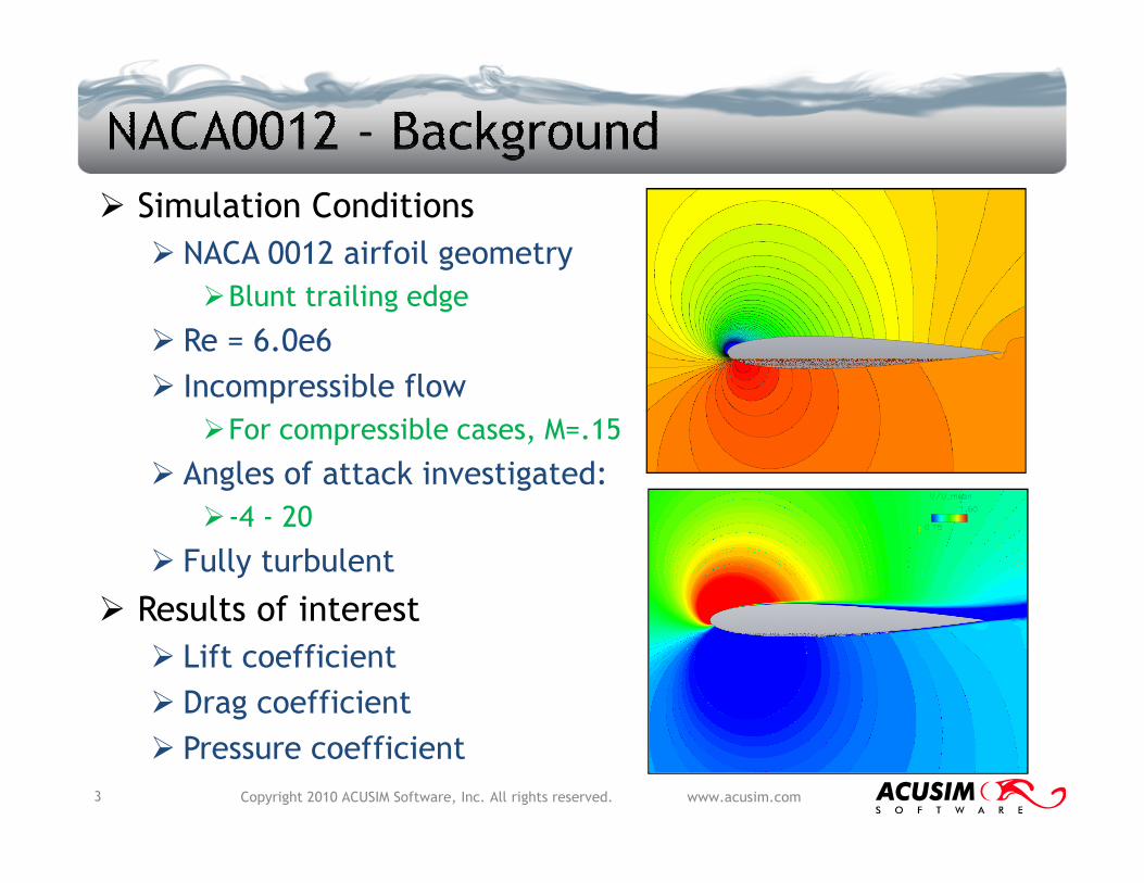
� Simulation Conditions
� NACA 0012 airfoil geometry
�Blunt trailing edge
� Re = 6.0e6
� Incompressible flow
�For compressible cases, M=.15
Copyright 2010 ACUSIM Software, Inc. All rights reserved. www.acusim.com
�For compressible cases, M=.15
� Angles of attack investigated:
�-4 - 20
� Fully turbulent
� Results of interest
� Lift coefficient
� Drag coefficient
� Pressure coefficient
3

� NACA 0012 airfoil geometry constructed using acuBuildFoil (GONE script)
� Chord = 1.0
� Trailing edge thickness = .002*chord
� Bounding cylinder diameter = 500*chord
� Span = 50*chord (2-d flowfield simulation)
� Surface tagging used to identify faces for boundary
Copyright 2010 ACUSIM Software, Inc. All rights reserved. www.acusim.com
� Surface tagging used to identify faces for boundary condition application/meshing
� Enables automated set-up of simulations
4
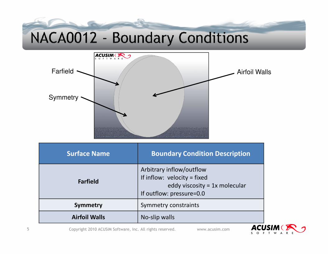
Farfield
Symmetry
Airfoil Walls
Copyright 2010 ACUSIM Software, Inc. All rights reserved. www.acusim.com5
Surface Name Boundary Condition Description
Farfield
Arbitrary inflow/outflow
If inflow: velocity = fixed
eddy viscosity = 1x molecular
If outflow: pressure=0.0
Symmetry Symmetry constraints
Airfoil Walls No-slip walls
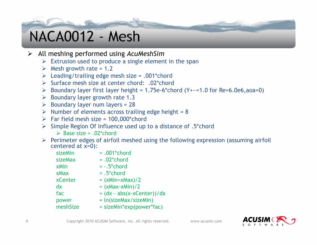
� All meshing performed using AcuMeshSim
� Extrusion used to produce a single element in the span
� Mesh growth rate = 1.2
� Leading/trailing edge mesh size = .001*chord
� Surface mesh size at center chord: .02*chord
� Boundary layer first layer height = 1.75e-6*chord (Y+~=1.0 for Re=6.0e6,aoa=0)
� Boundary layer growth rate 1.3
� Boundary layer num layers = 28
� Number of elements across trailing edge height = 8
� Far field mesh size = 100,000*chord
Simple Region Of Influence used up to a distance of .5*chord
Copyright 2010 ACUSIM Software, Inc. All rights reserved. www.acusim.com6
Far field mesh size = 100,000*chord
� Simple Region Of Influence used up to a distance of .5*chord� Base size = .02*chord
� Perimeter edges of airfoil meshed using the following expression (assuming airfoil centered at x=0):sizeMin = .001*chord
sizeMax = .02*chord
xMin = -.5*chord
xMax = .5*chord
xCenter = (xMin+xMax)/2
dx = (xMax-xMin)/2
fac = (dx – abs(x-xCenter))/dx
power = ln(sizeMax/sizeMin)
meshSize = sizeMin*exp(power*fac)

� Total number of nodes = 97,635
� Some optimization capability on model size, can be reduced
Copyright 2010 ACUSIM Software, Inc. All rights reserved. www.acusim.com7

� Drag Coefficient vs. Angle of Attack
Copyright 2010 ACUSIM Software, Inc. All rights reserved. www.acusim.com8
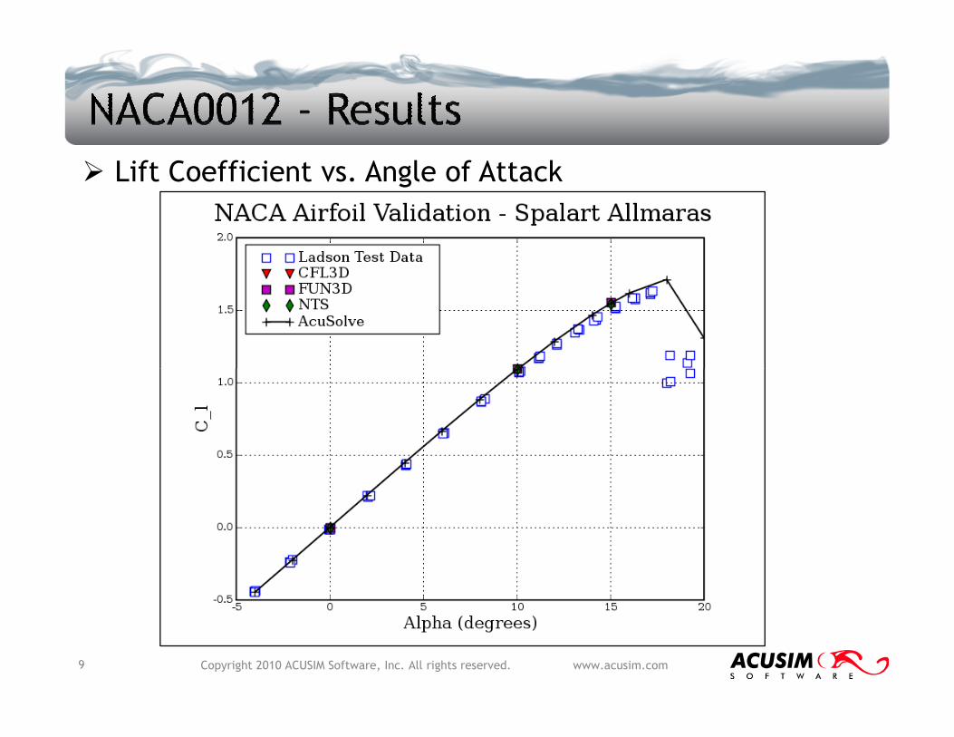
� Lift Coefficient vs. Angle of Attack
Copyright 2010 ACUSIM Software, Inc. All rights reserved. www.acusim.com9
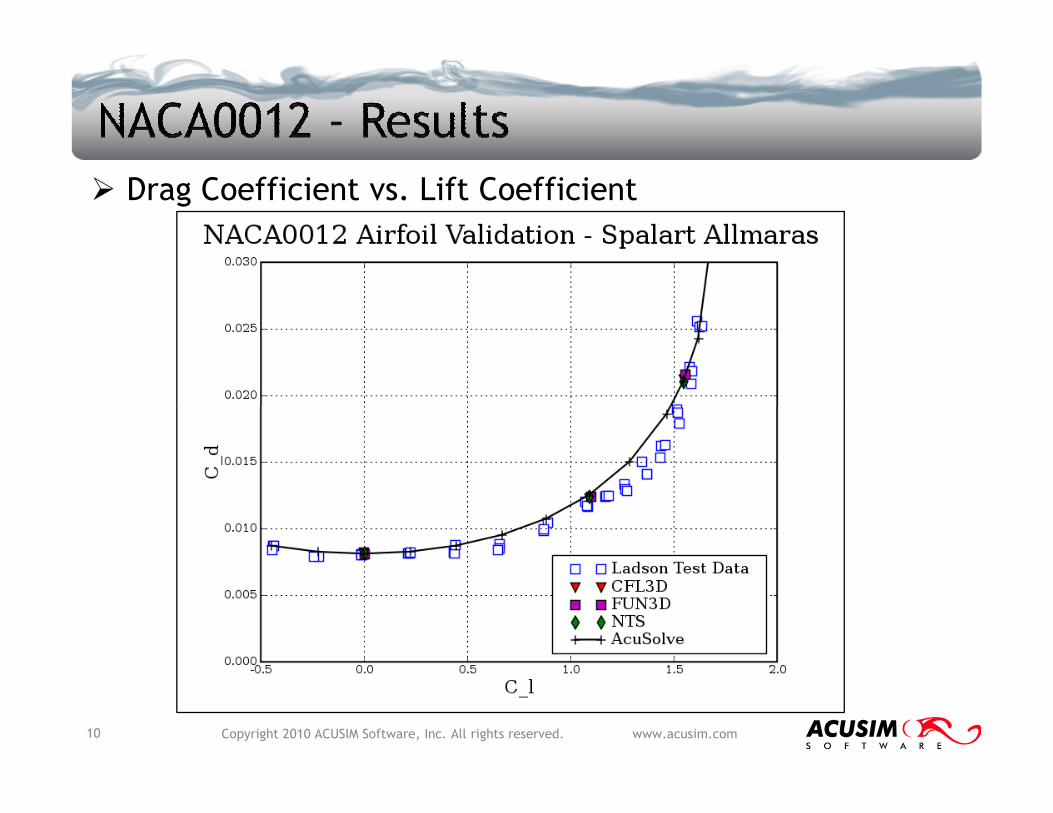
� Drag Coefficient vs. Lift Coefficient
Copyright 2010 ACUSIM Software, Inc. All rights reserved. www.acusim.com10
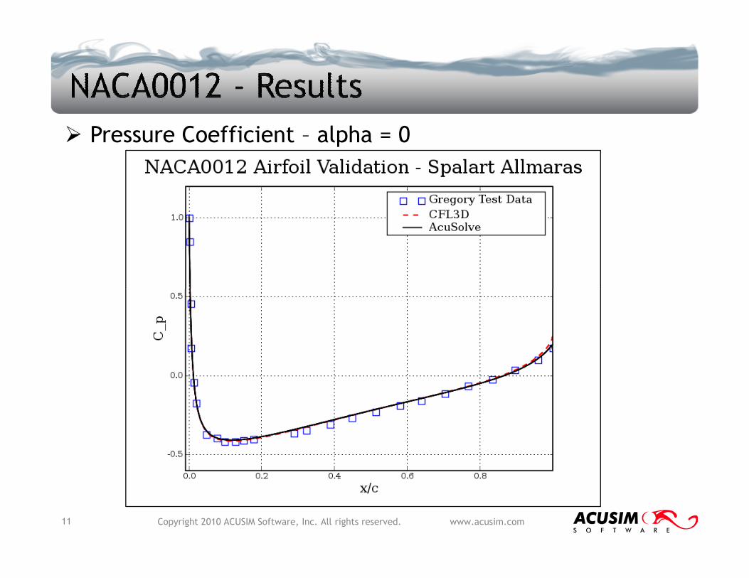
� Pressure Coefficient – alpha = 0
Copyright 2010 ACUSIM Software, Inc. All rights reserved. www.acusim.com11

� Pressure Coefficient – alpha = 10
Copyright 2010 ACUSIM Software, Inc. All rights reserved. www.acusim.com12
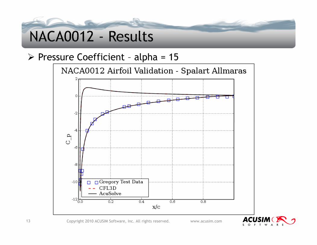
� Pressure Coefficient – alpha = 15
Copyright 2010 ACUSIM Software, Inc. All rights reserved. www.acusim.com13

� AcuSolve results agree very well with both
experimental data and other simulations
� AcuSolve simulations run on unstructured meshes
�Extensive mesh sensitivity study performed to show that
AcuSolve SA results are within 2% of complete grid
convergence
Copyright 2010 ACUSIM Software, Inc. All rights reserved. www.acusim.com14


![Low-Speed Aerodynamic Characteristics of NACA 0012 …naca.central.cranfield.ac.uk/reports/arc/rm/3726.pdf · · 2013-12-05Low-Speed Aerodynamic Characteristics of NACA 0012 Aerofoi]](https://static.fdocuments.us/doc/165x107/5aa786827f8b9a50528c845f/low-speed-aerodynamic-characteristics-of-naca-0012-naca-aerodynamic-characteristics.jpg)