NA-B RDM 121504 - Machine Automation Products · Features The RDM Series Index Drive is ideal for...
14
Features The RDM Series Index Drive is ideal for rotary dial applications with features including: ◆ Large Output Mounting Surface supported by 4-point contact bearing offering superior thrust and moment capacity ◆ Large Center Thru Hole ◆ Low Profile ◆ Complete, Motorized Drive Packages ◆ Optional Output Overload Clutch
Transcript of NA-B RDM 121504 - Machine Automation Products · Features The RDM Series Index Drive is ideal for...

FeaturesThe RDM Series Index Drive is ideal forrotary dial applications with featuresincluding:
◆ Large Output Mounting Surface supported by 4-point contact bearingoffering superior thrust and momentcapacity
◆ Large Center Thru Hole
◆ Low Profile
◆ Complete, Motorized Drive Packages
◆ Optional Output Overload Clutch

Industrial Motion Control, L.L.C. • www.camcoindex.com • (847) 459-5200
RDM Index Drives
B
B-2
80RDM Indexer Capacities
80RDM
205
4X M8 X 16
6 X 3.5(N9)
52.565
2X ø6.8,2X 8.8,
13080
FAR SIDE
80130
40
2X 19
15
230 80
65
ø107
FAR SIDE
NEAR SIDE4X M8,
4X ø
42
42
4X M6 X 12
13
42
13
42
98
ø80
ø125
ø160 h7 h6
1104
THRUø70
ALL DIMENSIONS = MILLIMETERS
Technical SpecificationsOutput Load Capacity – loads carried during index
Radial 730 lbs
Thrust/Axial 1,810 lbs
Moment 1,810 in.-lbs
Other Motions (stops and index periods) available. Contact your lMC sales representative for more information.
All dimensions are subject to change. For actual dimensions, please request the current drawing from IMC.
Typical Application Dial Diameter: 8 in. to 28 in.
Accuracy ±44 arcsec / ±.003" at 14" Radius
Repeatability ±22 arcsec / ±.0014" at 14" Radius
Stops Index Motion B10 Capacity Internal Inertia Model (S) Period (β) at 50 RPM (in-lb) (lb-in2)2 330 msc.50 716 28 80RDM2H16-330 3 330 msc.25 798 28 80RDM3H16-330 4 330 msc.33 1455 28 80RDM4H20-330 6 270 ms 1540 30 80RDM6H20-2708 270 ms 1197 29 80RDM8H16-270
270 ms 1661 30 80RDM12H20-27012 180 ms 1817 30 80RDM12H20-180
120 msc.33 2222 30 80RDM12H20-120 270 ms 1260 29 80RDM16H16-270
16180 ms 1392 29 80RDM16H16-180120 ms 1473 29 80RDM16H16-12090 msc.33 1724 29 80RDM16H16-90
24270 ms 2012 30 80RDM24H20-270 II180 ms 2233 30 80RDM24H20-180 II
32270 ms 1523 29 80RDM32H16-270 II180 ms 1681 29 80RDM32H16-180 II
4 360 c.v. 482 30 80RDM0H20-360 4:18 360 c.v. 370 29 80RDM0H16-360 8:112 360 c.v. 547 30 80RDM0H20-360 12:116 360 c.v. 384 29 80RDM0H16-360 16:1

Industrial Motion Control, L.L.C. • www.camcoindex.com • (847) 459-5200
RDM Index Drives
B
B-3
1900 RPM. 90V D.C. 1/3 HP MOTOR
MOTOR ADAPTERI.E.C. B14-71/105
ø19
140.8
90
205
50.7
UNDERSIDE OF MOUNTED DIAL PLATE. TO ELIMINATE INTERFERENCE WITH .250 THICK DIAL RISER (55C75387010000) WITH SINGLE EXTENSION MAY REQUIRE AR180 REDUCER MOUNTING "A" OR "B"WARNING NOTE:
h6
ø98.4
109.5
44.5 49
92.5
(34.3)
87.4
232.6
33
ALL DIMENSIONS = MILLIMETERS
◆ R180 Reducer (Ratios from 5:1 to 60:1)– Double Extended Worm Shaft (Input)– Worm Shaft Handwheel
◆ Double Extended Camshaft (Input Shaft)◆ Center Thru Hole (70 mm / 2.76 in. Diameter)◆ 1/3 hp DC Motor
Standard Package80RDM Indexer with
◆ Varipak DC Motor Control (up to 30 cpm)◆ Cycle Cam and Limit Switch Mounted to Camshaft◆ Right Hand Cam◆ Universal Mounting Capability
DIAL
4X M5 X 10
STATIONARY CENTER POSTø
ø
150
4
ø45
ø60 B.C.
CYCLE CAM &
LIMIT SWITCH
80RDM OPTIONS
Optional Accessories◆ 1/3 hp AC Drive Package with Inverter Duty Motor
and Inverter Drive (up to 60 cpm)◆ SW-030 or SW-040 reducer with Option Internal OLC◆ Stationary Center Post◆ Dual Cam and Limit Switch◆ Base Riser Blocks◆ Electric Clutch-Brake ◆ Air Motor Drive Package◆ 180IOC Input Overload Clutch ◆ Left Hand Cam◆ Relief in Dwell for shot-pin applications ◆ Custom Dial Plate
All dimensions are subject to change. For actual dimensions, please request the current drawing from IMC.
All dimensions are subject to change. For actual dimensions, please request the current drawingfrom IMC.

Industrial Motion Control, L.L.C. • www.camcoindex.com • (847) 459-5200
RDM Index Drives
B
B-4
601RDM Indexer Capacities
601RDM
2X ø 312
2X ø .3125
4X .312-18UNC
5X .250-20UNC
6X 312-18UNC
ø 8.66 ø 1.75ø 3.500
ø 6.50
2.16
.236 KEYWAY
.74862X ø
4.250
10.50
3.50
.25 5.94
4.59
6.69
4X ø .406
3.613.00
1.81
30°
3.00
1.81
30°
R5.09.375
45°ø 6.000
55°
ø 3.000
55°
8.66
THRU
6.69
±.01
+.000-.001
-+.0005
.0000
(6MM)
(19MM)
Technical SpecificationsOutput Load Capacity – loads carried during index
Radial 910 lbs
Thrust/Axial 2,270 lbs
Moment 3,180 in.-lbs
Other Motions (stops and index periods) available. Contact your lMC sales representative for more information.
All dimensions are subject to change. For actual dimensions, please request the current drawing from IMC.
Typical Application Dial Diameter: 12 in. to 36 in.
Accuracy ±39 arcsec / ±.003" at 18" Radius
Repeatability ±22 arcsec / ±.002" at 18" Radius
Stops Index Motion B10 Capacity Internal Inertia Model (S) Period (β) at 50 RPM (in-lb) (lb-in2)2 330 msc.67 1555 112 601RDM2H20-330 3 330 msc.33 2950 112 601RDM3H24-330 4 330 msc.33 3683 112 601RDM4H24-330 6 270 ms 4025 112 601RDM6H24-270
8270 msc.33 5035 112 601RDM8H24-270 180 msc.67 6758 112 601RDM8H24-180 270 ms 4452 112 601RDM12H24-270
12 180 ms 4985 112 601RDM12H24-180120 msc.33 6225 112 601RDM12H24-120 270 ms 4511 112 601RDM16H24-270
16 180 ms 5061 112 601RDM16H24-180120 msc.50 6780 112 601RDM16H24-120
24270 ms 5879 112 601RDM24H24-270 II180 ms 6479 112 601RDM24H24-180 II
32270 ms 5937 112 601RDM32H24-270 II180 ms 6651 112 601RDM32H24-180 II
4 360 c.v. 1110 110 601RDM0H24-360 4:16 360 c.v. 1212 110 601RDM0H24-360 6:18 360 c.v. 1274 112 601RDM0H24-360 8:112 360 c.v. 1286 110 601RDM0H24-360 12:1
Industrial Motion Control, L.L.C. • www.camcoindex.com • (847) 459-5200
RDM Index Drives
B
B-5
1/3 HP MOTOR1900 RPM, 90V D.C.
MOTOR ADAPTOR
ø.7846 (19MM)
4.47
6.47
8.47
4.31
3.88
3.72
3.44
9.16
1.30
2.161.75
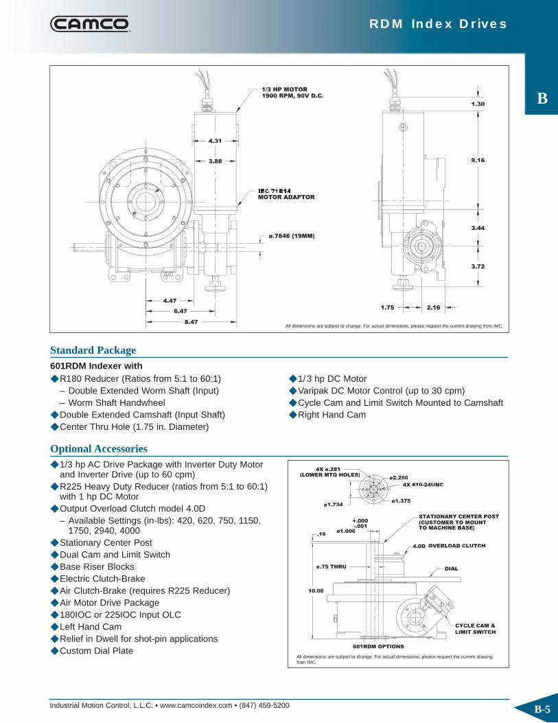
◆ R180 Reducer (Ratios from 5:1 to 60:1)– Double Extended Worm Shaft (Input)– Worm Shaft Handwheel
◆ Double Extended Camshaft (Input Shaft)◆ Center Thru Hole (1.75 in. Diameter)
Standard Package601RDM Indexer with
◆ 1/3 hp DC Motor◆ Varipak DC Motor Control (up to 30 cpm)◆ Cycle Cam and Limit Switch Mounted to Camshaft◆ Right Hand Cam
ø.75 THRU
10.00
.19ø1.000
+.000
4.0D
ø1.734
4X #10-24UNC
4X ø.281
DIAL
STATIONARY CENTER POST
ø1.375
ø2.250
CYCLE CAM &
LIMIT SWITCH
OVERLOAD CLUTCH
-.001(CUSTOMER TO MOUNTTO MACHINE BASE)
(LOWER MTG HOLES)
Optional Accessories◆ 1/3 hp AC Drive Package with Inverter Duty Motor
and Inverter Drive (up to 60 cpm) ◆ R225 Heavy Duty Reducer (ratios from 5:1 to 60:1)
with 1 hp DC Motor ◆ Output Overload Clutch model 4.0D
– Available Settings (in-lbs): 420, 620, 750, 1150,1750, 2940, 4000
◆ Stationary Center Post◆ Dual Cam and Limit Switch◆ Base Riser Blocks◆ Electric Clutch-Brake ◆ Air Clutch-Brake (requires R225 Reducer)◆ Air Motor Drive Package◆ 180IOC or 225IOC Input OLC ◆ Left Hand Cam◆ Relief in Dwell for shot-pin applications◆ Custom Dial Plate
All dimensions are subject to change. For actual dimensions, please request the current drawing from IMC.
All dimensions are subject to change. For actual dimensions, please request the current drawingfrom IMC.

Industrial Motion Control, L.L.C. • www.camcoindex.com • (847) 459-5200
RDM Index Drives
B
B-6
902RDM Indexer Capacities
902RDM
7.50
15.0013.75
.250 KEYWAY
4X .50-20UNF
6.000
5.19
4.56
5.19
4.56
3.064X ø.5622
2X ø.438
2X ø
4.38
(5X .38-16UNC)
6X .375-24UNF
12.251 5
2X ø.5000 X .88
.19
ø12.250
ø9.50
ø5.000
°
°
°
°
R7.00
ø4.250
ø8.375 5.50
6.88
2.75
7.500
ø2.25 THRU
+.000±.016
±.005
-.0000+.0005
( ) = OPTIONAL
Technical SpecificationsOutput Load Capacity – loads carried during index
Radial 3,540 lbs
Thrust/Axial 8,850 lbs
Moment 17,700 in.-lbs
Other Motions (stops and index periods) available. Contact your lMC sales representative for more information.
All dimensions are subject to change. For actual dimensions, please request the current drawing from IMC.
Typical Application Dial Diameter: 20 in. to 48 in.
Accuracy ±27 arcsec / ±.003" at 24" Radius
Repeatability ±13 arcsec / ±.0015" at 24" Radius
Stops Index Motion B10 Capacity Internal Inertia Model (S) Period (β) at 50 RPM (in-lb) (lb-in2)2 330 msc.67 5361 595 902RDM2H32-330 3 330 msc.33 5461 595 902RDM3H32-330 4 330 msc.33 6524 595 902RDM4H32-330 6 270 ms 6913 595 902RDM6H32-270
8270 ms 8833 612 902RDM8H32-270180 msc.33 8023 612 902RDM8H24-180270 ms 7726 595 902RDM12H32-270
12 180 ms 8751 595 902RDM12H32-180120 ms 9276 595 902RDM12H32-120270 ms 8711 612 902RDM16H32-270
16 180 ms 9599 612 902RDM16H32-180120 ms 10202 612 902RDM16H32-120
24270 ms 10877 595 902RDM24H32-270 II180 ms 11494 595 902RDM24H32-180 II
32270 ms 11877 612 902RDM32H32-270 II180 ms 13108 612 902RDM32H32-180 II
4 360 c.v. 2092 612 902RDM0H32-360 4:16 360 c.v. 2359 595 902RDM0H32-360 6:18 360 c.v. 2498 612 902RDM0H32-360 8:112 360 c.v. 2539 595 902RDM0H32-360 12:1

Industrial Motion Control, L.L.C. • www.camcoindex.com • (847) 459-5200
RDM Index Drives
B
B-7
8.62
5.195
ØØ.8750
2.75
13.001
1.75
2.75
7.50
+.0000-.0005
56C FRAME 9 AMP
1 HP MOTOR90V D.C. 1800 RPM TEFC
12.75 MAXØØ6.62
ØØ4.62
ØØ5.25
2.250
4.12
3.31
3.16
(OPTIONAL) RISER PACKAGE FOR USEWITH REDUCER MOUNTING C ANDOPTIONAL MOTOR (NOT REQUIRED IF REDUCER OVERHANGSTABLE)
3.12
56C MOTOR ADAPTOR
Ø.6875
4.81
.188 KEYWAY
-.0010+.0000
◆ R225 Reducer (Ratios from 5:1 to 60:1)◆ Double Extended Camshaft (Input Shaft)◆ Center Thru Hole (2.25 in. Diameter)◆ 1 hp DC Motor
Standard Package902RDM Indexer with
◆ Varipak DC Motor Control (up to 30 cpm)◆ Cycle Cam and Limit Switch Mounted to Camshaft◆ Right Hand Cam
10.12
Ø1.75 THRU
.25 Ø2.000-.001
4X .375-16UNC
7.8D
Ø3.375
DIAL
STATIONARY CENTER POST
+.000
Ø2.750
OVERLOAD CLUTCH
CYCLE CAM &LIMIT SWITCH
Optional Accessories◆ 1 hp AC Drive Package with Inverter Duty Motor
and Inverter Drive (up to 60 cpm)◆ R260 Reducer (Ratios from 5:1 to 60:1)◆ Output Overload Clutch model 7.8D
– Available Settings (in-lbs): 1400, 1700, 2600,3200, 4200, 5000, 7200, 10000
◆ Stationary Center Post◆ Dual Cam and Limit Switch◆ Base Riser Blocks◆ Electric Clutch-Brake◆ Air Clutch-Brake ◆ Air Motor Drive Package◆ 225IOC or 260IOC Input OLC◆ Left Hand Cam◆ Relief in Dwell for shot-pin applications◆ Custom Dial Plate
All dimensions are subject to change. For actual dimensions, please request the current drawing from IMC.
All dimensions are subject to change. For actual dimensions, please request the current drawingfrom IMC.

Industrial Motion Control, L.L.C. • www.camcoindex.com • (847) 459-5200
RDM Index Drives
B
B-8
1100RDM Indexer Capacities
1100RDM
6X M12 X 24
X 242X ø12H6
4X ø16.6
12 X 5 N9
2X ø11.9
[5X M12 X 22]
8X M12 X 24
8X M12 X 24
[ ] = OPTIONAL
290
2X ø40h5
[2X 45°]
108108
175
145
290175
145
[2X 30°]
ø260ø210
[ø405]
145
380
145
R215
73
19
91
190.5
455
73
90
73
73
230
ø290
h6ø380
150
h6ø190
6
ø130
180
16
ALL DIMENSIONS = MILLIMETERS
Technical SpecificationsOutput Load Capacity – loads carried during index
Radial 8744 lbs
Thrust/Axial 20,179 lbs
Moment 24,214 in-lbs
Other Motions (stops and index periods) available. Contact your lMC sales representative for more information.
All dimensions are subject to change. For actual dimensions, please request the current drawing from IMC.
Typical Application Dial Diameter: 20 in. to 60 in.
Accuracy ±22 arcsec / ±.003" at 30" Radius
Repeatability ±11 arcsec / ±.0016" at 30" Radius
Stops Index Motion B10 Capacity Internal Inertia Model (S) Period (β) at 50 RPM (in-lb) (lb-in2)2 330 msc.67 13248 1978 1100RDM2H40-3303 330 msc.50 15169 1907 1100RDM3H40-3304 330 msc.33 21780 2019 1100RDM4H48-3306 270 msc.25 25957 2019 1100RDM6H48-270
8 270 ms 18443 1955 1100RDM8H40-270180 msc.50 24196 1955 1100RDM8H40-180270 ms 23992 2019 1100RDM12H48-270
12 180 ms 27161 2019 1100RDM12H48-180120 ms 21709 1907 1100RDM12H40-120270 ms 18824 1955 1100RDM16H40-270
16 180 ms 20824 1907 1100RDM16H40-180120 msc.25 24373 1955 1100RDM16H40-120
24 270 ms 31373 2019 1100RDM24H48-270 II180 ms 35117 2019 1100RDM24H48-180 II
32 270 ms 25453 1955 1100RDM32H40-270 II180 ms 28258 1907 1100RDM32H40-180 II

Industrial Motion Control, L.L.C. • www.camcoindex.com • (847) 459-5200
RDM Index Drives
B
B-9
(1.000") OPTIONAL
292.5
290 396
ø 179
90125 74
(170) OPTIONAL
243
76.2[3.00"]
401
145TC MOTOR
ADAPTOR
1.5 HP MOTOR,
TEFC 180V D.C.,
1800 RPM
ALL DIMENSIONS = MILLIMETERS
◆ 7300C Reducer (Ratios from 5:1 to 60:1)◆ Double Extended Camshaft (Input Shaft)◆ Center Thru Hole (130 mm / 5.1 in. Diameter)◆ 1.5 hp DC motor
Standard Package1100RDM Indexer with
◆ Varipak DC Motor Control (up to 30 cpm)◆ Cycle Cam and Limit Switch Mounted to Camshaft◆ Right Hand Cam
MOTOR FRAME
OPTIONAL BRAKE MOTOR
SEW KH47
"DM"
197
145
145
197
IEC71
IEC90
IEC80
IEC100
"LB""LM"
269
319
199
249
85
85
64
64
1100RDM WITH OPTIONAL KH47 REDUCER
73
(22) 76166
"DM"
7.2
"LM""LB"
Optional Accessories◆ KH47 Reducer and AC Motor with Optional Brake◆ AC drive package with Inverter Duty Motor and
Inverter Drive (up to 60 cpm)◆ 7350C Heavy Duty Reducer (Ratios from 5:1 to 60:1)◆ Stationary Center Post◆ Dual Cam and Limit Switch◆ Electric Clutch-Brake◆ Air Clutch Brake◆ 300IOC Input OLC◆ Left Hand Cam◆ Relief in Dwell for shot-pin applications◆ Custom Dial Plate
All dimensions are subject to change. For actual dimensions, please request the current drawing from IMC.
All dimensions are subject to change. For actual dimensions, please request the current drawingfrom IMC.
Industrial Motion Control, L.L.C. • www.camcoindex.com • (847) 459-5200
RDM Index Drives
B
B-10
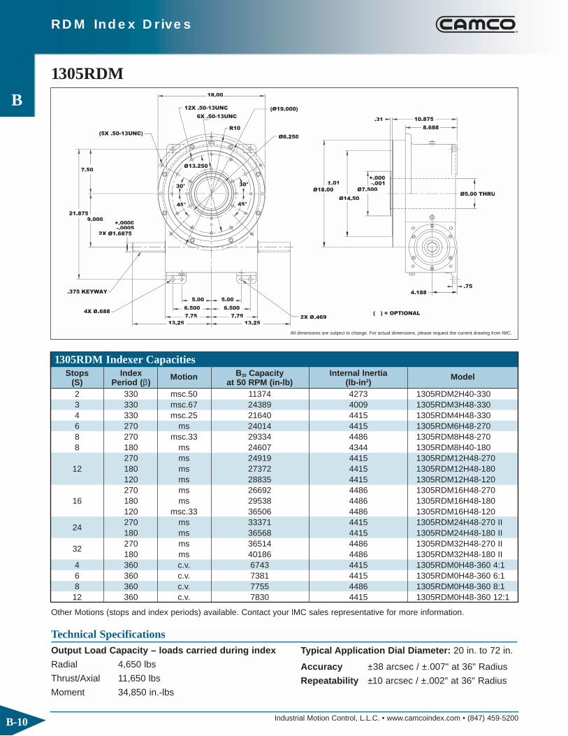
1305RDM Indexer Capacities
1305RDM
+.0000
+.000±.01
4.188
.75
Ø5.00 THRU
.31 10.875
8.688
Ø18.00
Ø14.50
Ø7.500
45°45
30
(5X .50-13UNC)
18.00
12X .50-13UNC
6X .50-13UNC
R10
21.875
7.50
9.000
4X Ø.6882X Ø.469
.375 KEYWAY
2X Ø1.6875
13.25
7.757.75
6.5006.500
5.005.00
Ø8.250
Ø
(Ø19.000)
( ) = OPTIONAL
13.25
-.0005
Technical SpecificationsOutput Load Capacity – loads carried during index
Radial 4,650 lbs
Thrust/Axial 11,650 lbs
Moment 34,850 in.-lbs
Other Motions (stops and index periods) available. Contact your lMC sales representative for more information.
All dimensions are subject to change. For actual dimensions, please request the current drawing from IMC.
Typical Application Dial Diameter: 20 in. to 72 in.
Accuracy ±38 arcsec / ±.007" at 36" Radius
Repeatability ±10 arcsec / ±.002" at 36" Radius
Stops Index Motion B10 Capacity Internal Inertia Model (S) Period (β) at 50 RPM (in-lb) (lb-in2)2 330 msc.50 11374 4273 1305RDM2H40-3303 330 msc.67 24389 4009 1305RDM3H48-3304 330 msc.25 21640 4415 1305RDM4H48-3306 270 ms 24014 4415 1305RDM6H48-2708 270 msc.33 29334 4486 1305RDM8H48-2708 180 ms 24607 4344 1305RDM8H40-180
270 ms 24919 4415 1305RDM12H48-27012 180 ms 27372 4415 1305RDM12H48-180
120 ms 28835 4415 1305RDM12H48-120270 ms 26692 4486 1305RDM16H48-270
16 180 ms 29538 4486 1305RDM16H48-180120 msc.33 36506 4486 1305RDM16H48-120
24270 ms 33371 4415 1305RDM24H48-270 II180 ms 36568 4415 1305RDM24H48-180 II
32270 ms 36514 4486 1305RDM32H48-270 II180 ms 40186 4486 1305RDM32H48-180 II
4 360 c.v. 6743 4415 1305RDM0H48-360 4:16 360 c.v. 7381 4415 1305RDM0H48-360 6:18 360 c.v. 7755 4486 1305RDM0H48-360 8:112 360 c.v. 7830 4415 1305RDM0H48-360 12:1

Industrial Motion Control, L.L.C. • www.camcoindex.com • (847) 459-5200
RDM Index Drives
B
B-11
(Ø1.000)
16.44
12.38
7.75 3.62
Ø1.6875
+.0000-.0005
6.633
3.000
11.3
4.5
9.56
145TC MOTOR
ADAPTOR
16.50 (OPTIONAL) RISER
PACKAGE FOR USE
WITH REDUCER
MTG. "D". (NOT
REQUIRED
IF REDUCER
OVERHANGS
TABLE.)
2 HP. MOTOR180 VDC., 1800 RPM., TEFC
6.977
.75
WORMSHAFT EXTENSION(OPTIONAL)
(6.69)
◆ 7300C Reducer (Ratios from 5:1 to 60:1)◆ Double Extended Camshaft (Input Shaft)◆ Center Thru Hole (5.00 in. Diameter)◆ 2 hp DC Motor
Standard Package1305RDM Indexer with
◆ Varipak DC Motor Control (up to 30 cpm)◆ Cycle Cam and Limit Switch Mounted to Camshaft◆ Right Hand Cam
Ø3.50 THRU
16.12
.25
6X Ø.531
Ø
6X .38-16UNC
32D
Ø4.990
DIAL
STATIONARY CENTER POST
CYCLE CAM &LIMIT SWITCH
Ø6.5000Ø4.375
OVERLOAD CLUTCH
-.001+.000
(CUSTOMER TO MOUNTTO MACHINE BASE)
1305RDM OPTIONS
(LOWER MTG HOLES)
Optional Accessories◆ 2 hp AC Drive Package with Inverter Duty Motor
and Inverter Drive (up to 60 cpm) ◆ 7350C Heavy Duty Reducer (Ratios from 5:1 to 60:1)◆ Output Overload Clutch model 32D
– Available Settings (in-lbs): 8500, 13000,20000, 31000
◆ Stationary Center Post◆ Dual Cam and Limit Switch◆ Base Riser Blocks◆ Electric Clutch-Brake◆ Air Clutch-Brake◆ 300IOC or 350IOC Input OLC◆ Left Hand Cam◆ Relief in Dwell for shot-pin applications◆ Custom Dial Plate
All dimensions are subject to change. For actual dimensions, please request the current drawing from IMC.
All dimensions are subject to change. For actual dimensions, please request the current drawingfrom IMC.

Industrial Motion Control, L.L.C. • www.camcoindex.com • (847) 459-5200
RDM Index Drives
B
B-12
1800RDM Indexer Capacities
1800RDM
5X .625-11
4X Ø.594
.500 KEYWAY
15.500.31
Ø20.38
8X .625-11
4.250
4.250
1.12
6.250
4.250
-.001Ø9.000±.01 Ø6.50
2X Ø2.1875
11.50
24.50
R13.5
30°
31.250
12.500
15.75
°°
9.500
7.25
10.75
30°
45°
9.500
10.752X Ø.594
15.75
4X Ø.781
22.5°
X 1.25 DEEP
7.25
Ø20.50
1.38 DEEP
+.000
12X .625-11 8X .625-11X 1.25 DEEP
X 1.25 DEEP
X 1.00 DEEP
Ø10.000
Technical SpecificationsOutput Load Capacity – loads carried during index
Radial 5,850 lbs
Thrust/Axial 14,550 lbs
Moment 61,200 in.-lbs
Other Motions (stops and index periods) available. Contact your lMC sales representative for more information.
All dimensions are subject to change. For actual dimensions, please request the current drawing from IMC.
Typical Application Dial Diameter: 26 in. to 96 in.
Accuracy ±27 arcsec / ±.006" at 48" Radius
Repeatability ±7 arcsec / ±.0016" at 48" Radius
Stops Index Motion B10 Capacity Internal Inertia Model (S) Period (β) at 50 RPM (in-lb) (lb-in2)2 330 msc.50 27554 18407 1800RDM2H56-330 3 330 msc.33 48803 18407 1800RDM3H64-330 4 330 msc.25 56570 18407 1800RDM4H64-330 6 270 ms 64301 18407 1800RDM6H64-2708 270 ms 64868 18985 1800RDM8H64-270
270 ms 71214 18407 1800RDM12H64-27012 180 ms 77925 18407 1800RDM12H64-180
120 ms 81918 18407 1800RDM12H64-120270 ms 64035 18985 1800RDM16H64-270
16 180 ms 71219 18985 1800RDM16H64-180120 msc.33 86845 18407 1800RDM16H64-120
24270 ms 86546 18407 1800RDM24H64-270 II180 ms 93113 18985 1800RDM24H64-180 II
32270 ms 86288 18985 1800RDM32H64-270 II180 ms 96447 18985 1800RDM32H64-180 II
4 360 c.v. 15430 18985 1800RDM0H64-360 4:16 360 c.v. 16867 18985 1800RDM0H64-360 6:18 360 c.v. 17710 18985 1800RDM0H64-360 8:112 360 c.v. 17875 18985 1800RDM0H64-360 12:116 360 c.v. 18410 18985 1800RDM0H64-360 16:1

Industrial Motion Control, L.L.C. • www.camcoindex.com • (847) 459-5200
RDM Index Drives
B
B-13
180 V.DC.,1800RPM, TEFC3 HP. MOTOR
10.75
ø2.1875
17.50
5.00
1.00
4.000
15.19
6.2506
MOTOR ADAPTOR145TC
(ø1.500)
10.94
(19.75)
(ø8.50)15.500
6.00 TYP
(OPTIONAL) RISER MAY BE USED WITHMTG. "C" TO PROVIDEREDUCER CLEARANCEWITH TABLE.
(3.00)
(9.31)
WORMSHAFT EXTENSION(OPTIONAL)
◆ 7400C Reducer (Ratios from 5:1 to 60:1)◆ Double Extended Camshaft (Input Shaft)◆ Center Thru Hole (6.50 in. Diameter)
Standard Package1800RDM Indexer with
◆ 3 hp DC Motor◆ Cycle Cam and Limit Switch Mounted to Camshaft◆ Right Hand Cam
6X .437-14UNCX .88 DEEPON 5.812 B.C.
6X .781 ø EQ. SP.ON 8.500 B.C.(LOWER MOUNTINGHOLES)
22.00
CONDUIT ENTRY
CYCLE CAM &LIMIT SWITCH
DIAL
61D OVERLOAD CLUTCH (OPTIONAL)
STATIONARY CENTER POST (CUSTOMER TOMOUNT TO MACHINEBASE)ø5.125
4.75 ø THRUHOLE
.25
+.000
ø6.490
1800RDM OPTIONS
Optional Accessories◆ 2 or 3 hp AC Drive Package with Inverter Duty Motor
and Inverter Drive (up to 60 cpm) ◆ 2 hp DC Motor with Varipak DC Motor Control
(up to 30 cpm) ◆ 7500C Heavy Duty Reducer (Ratios from 5:1 to 60:1)◆ Output Overload Clutch model 61D
– Available Settings (in-lbs): 23000, 36000, 44000,50000, 60000
◆ Stationary Center Post◆ Dual Cam and Limit Switch◆ Base Riser Blocks◆ Electric Clutch-Brake◆ Air Clutch-Brake◆ 400IOC or 500IOC Input OLC◆ Left Hand Cam◆ Relief in Dwell for shot-pin applications◆ Custom Dial Plate
All dimensions are subject to change. For actual dimensions, please request the current drawing from IMC.
All dimensions are subject to change. For actual dimensions, please request the current drawingfrom IMC.

Industrial Motion Control, L.L.C. • www.camcoindex.com • (847) 459-5200
RDM Index Drives
B
B-14
1. Model
2. Input Shaft Configuration◆ Side 1◆ Side 2◆ Double Input – DI (Standard)
1. Model
2. Ratio◆ 5:1, 10:1, 15:1, 20:1, 25:1, 30:1, 40:1, 50:1, 60:1
3. Motor Adapter
4. Reducer Input Shaft Extension◆ Single Input (SE) or Double Input (DE)
Indexer Ordering Procedure3. Cam Lead (Helix)
◆ Right Hand (Standard)◆ Left Hand
NOTE: Input may rotate in either direction to achievedesired direction of output rotation.
4. Indexer Mounting Position: 1-6
Reducer Ordering Procedure5. Mounting
◆ Mounting Position A, B, C, or D◆ Mounted on Indexer Side 1 or Side 2
6. Input Shaft Orientation◆ Left or Right (See Diagram Below)
* Consult IMC for availability of this mounting
AE: Input Shaft
Position of Shafts Indexer Mounting Position
(Standard)
Double Input (DI)
Cam Lead
Right Hand Left Hand
5
AS
AE
Input
3
1
AS: Output Shaft
AE
6AE
AS
AS
AS
AE
4
AE
AS 2
AS
AE
A-1-RH
A-2-LH B-2-LH B-2-RH A-2-RH C-2-LH D-2-RH C-2-RH D-2-LH
B-1-RH B-1-LH A-1-LH C-1-RH D-1-LH C-1-LH D-1-RH
Reducer Mounting Position


![RDM [module] RDM-[module]-1… · medium rdm-[module]-15 aheeehapkfgloppjljhoekmmlaanogfkbpaheeeha bnfffnbpepadepelacadbhecbkjpbhfgnpbnfffnb jaibeeflfohfjhjkaphgbjahblpaggncggelagnep](https://static.fdocuments.us/doc/165x107/5fa322a37cebb95cfe55ebc7/rdm-module-rdm-module-1-medium-rdm-module-15-aheeehapkfgloppjljhoekmmlaanogfkbpaheeeha.jpg)