N65 230 00 , i - NASA · N65 230 00 ,::_": OTS PRICE(S) ... George C. Marshall Space Flight Center...
178
_--- III II I _ P II __ LII I1'1 J] .... I .4 -, A, ; 4b,.o--- _- ye "m"*_wi_.4alp_ _ • ,. 5 ,t ! ,: . -_C. 2, • o _. -_ ..... ._. -;._. c GPO PRICE $ .... _ .N65 230 00 ,::_" OTS PRICE(S) $ _ _cc.._o.-.v...., "- =..u, ,_. , i /Y?" __. __J .-- .< _. (pAGI[II- _ ¢C0D£) ._ .-', Hard copy (HC) J_ _ .d_ /' ,,}_"-;,H _ - .. /" _ _ CNAIA CR Ol_ TMX OR-AD NUMb[It) :cA'rEGoHY) , Microfiche (MF)_ /" U U _, m_lll_i __d T®3 Ird._l_'-" J " _.r,- ,_ -" ....... :-,__ - ___ -_- "*_, _--r_ ._ - ",' Ik t ' ,,, ." ADVANCi_ TECHNOLOGY L,A_DRATO_S :,_,,," "/"_', " _ AO_V_StONOF. ' .:'" _ .*"_"._. '_.'t https://ntrs.nasa.gov/search.jsp?R=19650013399 2018-07-15T17:32:56+00:00Z
Transcript of N65 230 00 , i - NASA · N65 230 00 ,::_": OTS PRICE(S) ... George C. Marshall Space Flight Center...

_--- III II I _ P II __ LII I1'1 J] .... I
.4 -, A,; 4b,.o--- _- ye "m"*_wi_.4alp_ _
• ,.
5
,t ! ,: . -_C.2,
• o _. -_
..... ._. -;._.c
GPO PRICE $ .... _ .N6 5 230 00 ,: :_":OTS PRICE(S) $ _ _cc.._o.-.v...., "- =..u, ,_.
, i /Y?" __. __J .--,:?_.<
_. (pAGI[II- _ ¢C0D£) ._ .-',
Hard copy (HC) J_ _ .d_ /' ,,}_"-;,H _ - ../" _ _ CNAIA CR Ol_ TMX OR-AD NUMb[It) :cA'rEGoHY) ,
Microfiche (MF)_ /" U U _,
m_lll_i __dT®3Ird._l_'-"J " _.r,- , _ - "....... :-,__
- ___ -_- "*_,_--r_ ._ - ",'
Ikt
' ,,, ." ADVANCi_ TECHNOLOGY L,A_DRATO_S :,_,,," "/"_'," _ A O_V_StONOF. ' .:' " _ .*"_"._.
'_.'t
1965013399
https://ntrs.nasa.gov/search.jsp?R=19650013399 2018-07-15T17:32:56+00:00Z
Final Report
HEAT-FLUX-TRANSDUCER DESIGNS AND
EFFECT OF THERMAL DISTURBANCES
ON TRANSDUCER PERFORMANCE
ATL Job 1230401
ATI,-D-: 271 _'_ October 1964
l
for
Nationai Aeronautics and Space Adminie'trationGeorge C. Marshall Space Flight Center
Contract No. NAS8-5323
Covering work performed fromJune 1963 through October 1964
Submitted by. Approved by:R. C. Bachmann R.W. Towle
J. T. Chambers
W. H. Giedt (Consultant)
"b
American Radiator & Standard Sanitary CorporationAdvanced Technology Laboratories Divisiou
3C9 Whisman Road
Mountain View, C_lifornia
ADVANCEO _KC_NOLOOY _AtJC}RATO_IEB OIVI_ION
I
I i i I
1965013399-002

FOREWORD
This report was prepared by Am,:rican Radiator & Standard Sa._Jitary Corporation,
Advanced Technology Laboratories (ATL) Division, Meuntain View, Caliiornia. "he
work was performed under Contract No. NAS8-53_3, National Aerona,}t_cs and Space
Administration (NASA), George C. Mar3hall Spuce Flight Center, Huntsville, Alabama.
The technical representative fer the NASA contracting ofhcer was V. L. Glasgow,
R-P&VE-PTF.
Principal investigators for ATL were P.. C. Bachm,_m and D. R. Hornbaker.
Dr. W. H. Giedt, Professor of Aeronautical Services at the University of California,
Berkeley, acted as consultanL
i i i r
1965013399-003

I I H _, ,, |! t
! |
CON I'ENTB
List of Illu_'trations iv
" Summary 1
: l_trodu ction 2 '_"I| Ca!orf.meter-Induced Disturbances 4
A. Necessity for Accurate Heat-Flux Measurements 4[
i B. Cross Conduction 4
C. SurfaceJI emperature Discontinuities 5• Ii D. Analysis of Effects of Nonisothermal Surface on Convective-Heating
Measurements 6't
1. Anal}_ict 1 Results 6
' _ 2. ApplicatiGn of Theory to Heat-Flux Measurements 7
}- i _ E. Simulation Theory 94t.
F. Calorimeter Calibration 9
• _- Heating Apparatus 11
,, Experimental Procedures 13
: $ A. Reference Heat-Flux lVIeasurements 13"4 t _r:
1. Radiant-Heating Reference Meter 14
|- 2. Convective- and Total-Heating Reference Me*er i5L
B. Test Program 16L
• _ C. Data Acquisition 17
+ D. Data Red_:.-'t'.m 17
i Experimental Results and Disc_£ssion 18 _i+ .
A. N-]23 Copper-Slug Radiometer ]8
1 1. Unpurged N-123 Radiometer 18 p2. Purged N-123 Radiometer 19 :
3. Combined Radiant-Convective Heatir_g of Purged N-123 .Radiometer 21
B. Slug-Type Total Calorimeters 2-_? +
1. Copper-Slug Total Calorimeter 24 :
[ 2. Nickel-Slug Tctal 3alo:imeter 27. +
C. C-1118 Mefabrane Tot._l Calorimeter 33
' i 1. Effect of Surface.-Temperature L i_ontinuity 33! 2. Transpiration Study 40
I_ D. Radiant-He': _,_g _tudies 42
E. Gas-Wempvr,_ureProbe <_(_/_ 46- ii - Emc_P_landa_
&OVANC<_ '¢ECHNO*.OC, W I,,AllOl_$_O_,lr_ _,VIIIION
+
] 9650 ] 3399-004

30_;TEN fS
(concl.)
Conclusions 48
Recommendations 50 "
Nomenclature 51
References 53r
Illustratibns 55
Appen(lx - Tabulated I_ata and Results
Distribution
d
u
.,o
i i ii i ii u i i i
1965013399-005
!LIST OF ILLUSTRATIONS
Figure No. Title
1 Analytical Models
2 Numerical Values of Coefficient_ in Equation 6
3 Experimental Heating Apparatus
4 Laboratory Heating Apparatus, Front View
5 Laboratory Heating Apparatus, Rear View
6 Heating Apparatus Test Section
7 Internal View of Radiant Heater and Test Section
Temperature Histories of Laboratory Reference Calorimeters During
Typical Heating Tests
9 Schematic of Purged N-123 Copper-Slug Radiometer (Showing Thermo- ._
couple Locaticns) !
10 Temperature Histories of Unpurged N-123 Radiometer Mounted in Water-Cooled 1/8"-Thick Coppec Plate Under Radiar _.Heating (Reference Heat
Flux = 7.3 Btu/ft2-sec)
11 Temperature Histories of Unpurged N- 123 Radiometer Mounted in Uncooled
1/8"-Thick Copper Plate Under Radiant Heating (Reference H_:atFlux = 17.4 Btu/ft2-sec) i
12 Temperature Histories of Unpurged N-123 Radiometer Mounted iu Water- iCooled 1/8"-Thick Copper Plate Under Radiant Heating (Reference Heat
Flux = 30.8 Btu/ft2-sec)
13 Temperature Histories of Unpurged N-123 Radiometer Mounted in Uncooled1/8"-Thick Copper Plate Under Radiaut Heating (Reference Heat
Flux = 3C. 1 Btu/ft2-sec)
14 Unpurge, _. N- 123 Radiometer Calibration at 100°F Under Radiant Heating
15 Ur_,,,lrged N.-123 Radiometer Calibration at 200°F Under Radiant Heating
16 Unpurged N-12_ Radiometer Calibration at 300°F Under Radiant Heating
i7 Unpurged N-123 Radiometer Calibrat._on at 400°F Under Radiant tteating
18 Unpurged N-123 Radiometer Calibratio_ at 500_F Under Radiant Heating
19 Unpurged N-123 Radio_neter Calibration _t 600°F Under Radiant Heating
20 Temperature Hl_tories of Purged N-123 Ra,tiometer Mounted in Water-Cooled 1/8"-Thick Copper Plate Under Radkmt Heating (Reference Heat ;.
Flux = 9.3 Btu/ft2-sec)y
-- iv - ADV,,NCrD T_CHNOL_QV LAmO_AVO_IES DIVImlON
1965013399-006
IILI I .... I _ __ ,_,,.I_ i II II .... j ....
LIST OF ILLUSTRATIONS
(cont.)
Figure No. Title
21 Temperature Histories ,of Purged N-12_ Radiometer Mounted in Uncooled.t/8"-Thick Coppe_ Plate Under Radiant Heating (Reference HeatFlux = 17.2 Btu/ft2-se. ,)
22 Temperature Histories of Purged N-123 Radiometer Mounted in Water-
Cooled 1/8"-Thick Copper Plate Under Radiant Heating (Reference HeatFlux = 26.7 Btu/ft2-sec)
23 Temperature Histories of Purged N-123 Radiometer Mounted in Uncooled1/8"-Thick Copper Plate Under Radiant Heating (Reference Heat
Flux = 37.2 Btu/ft2-sec)
24 Purged N-123 Radiometer Ca!ibratinn at 200°F Under Radiant Heating'
25 Purged N-123 Radiometer Calibration at 300°F Under Radiant Heating:
26 Purged N-123 Radiometer Calibration at 400°F Under Radiant Heating
27 Purged N-123 Radiometer Calibration _t 500°F Under Radiant Heating
28 Purged N-123 Radiometer Calibration at 6fl0°F Under Radiant Heating
29 Purged N-123 Radiometer Calibration at 700°F Under Radiant He_ting
30 Purged N-123 Radiometer Calibration Curves for Indicated Copr_er-Slug t:Temperaturer. Under Radiant Heating
31 Comparison of Calibrations Under Combined Radiant-Convective and
Radiant Heating at 200°F for Purged N-123 Radiometer
32 Comparison of Calibrations Under Combined Radiant-Convective and
Radiant Heating at 300°F for Purged N-123 Radiometer
33 Temperature l_istories of Purged N-123 Rgdiometer Mouuted in Water-Cooled 1/8"-Thick Copper Plate Under Combined Radiant-Convective
Heating (Reference be_.t Flux = 6.3 _tu/ft2-sec)
34 Temperature Histories of Purged N-123 Radiometer Mounted in Water-
Cocled 1/8"-Thick Copper Plate Under Combined Radiant-ConvectiveHeating (Reference tIeat Flux = 11 Btu/ft2-sec)
35 Dimensions of Fenwal Coppe_- and NickeJ-Slug Total Calorimeters
3_ Mounting Condition and Thermocouple Location for Radiant-Heating Tests
c,n Feuwal Copper-Slug Calommeter and Early Radiant-Heating Te_ts onFenwal Nickei-_iug Total Calorimeter
37 Mounting Condition and Thermocouple Location for Femval Nickel-Slug
Total Calorimeter Mounted in 1/8"-Thick Copper Plate and in M-.'I Heat-Shiel, Material
-- V - A_"*'ANCIEU TlCCHN¢_OQV LAIOM,_'IO_HKa OIV_IION
"1965013399-007
? .... _........... _ ....... -.--L--Z._ -- -C .... I +. _- L II _ Illl_.. 1,7__ " ..... 1 _
i
LIST OF ILLUSTRATIONS
(cont.)
Figure No. Title
! 38 Temperature Histories of Copper-Slug Total Calorimeter Mounted m
Uncooled 1/8"-Thick Copper Plate Under Radiant Heating (Reference
• Heat Flux = 15.1 Btu/ft2-sec)+?
39 temperature Histories of Copper--Slug Total Calorimeter Mounted m
Uncooled 1/8"-Thick Copper PMte Under Radiant HeatJ_lg (ReferenceHeat Fiux= 18.0 Btu/ft2-sec)
40 Temperature Histozies of Copper +Slug Total Calorimeter Mounted in
Uncooled 1/8"-Thick Copper Plate Und3r Radiant Heating (ReferenceHeat Flux = 27.5 Btu/ft2-sec)
41 Temperature Histories of Copper-Slug Total Calorimeter Mounted in
Uncooled 1/8"-Thick Copper Plate Under Radiant Heating (ReferenceHeat Flux = 37.5 Btu/ft2-sec)
42 Temperature Histories of Copper-Slug Total Calorimeter Mounted m
Uncooled 1/8"-Thick Copper Plate Under Radiant Heating (ReferenceHeat Flux = 40.8 Btu/ft2-sec)
43 Temperature Histories of Copper-,glug Total Calorimeter Mounted in
Uncooled 1/8"-Thick Copper Plate Under Radiant Heating (Reference
Heat Flux = 41.0 Btu/ft2-sec)
44 Temperature Histories of r_i:pe1,-+Slug Total Calorimeter Mounted m
Water-Cooled _/8"-Thick Copper Plate Under Radiant Heating (Reference
IIeat Flux = 7.6 Btu/ft2-sec)
45 TemperaLure Iiis_ories of Copper-Slug To'_a! Calorimeter Mounted mWater-Cooled 1/8"-Thick Copper Plate Under Rad_:: +.Heating (Reference
Heat Flux = _._._+ ,_ Btu/ft2-sec)
46 Temperature Histor.+es of Copper-Slug Tot_] Calori__+/_r b/ounted ,-n
Water-Cooled 1,/_"-Thlck Copper Plate Uuder Rad-am ',+eating (Refe,-ence _Iteat Flux = 15.9 P_tu/ft2-sec) I
47 Temperature H_3_,ories of Copper-Slug Total Cat +,:_,_,,_<ter Mounted. in •
Water-Cooled 1/8 "--Thick Copper Plate Under/l_. _.... _ Heating (_'-Jference
'_ Heat Flux = 22.9 bt_:/ft2-sec)
48 Temperature Histories of +,.c_per-Slug To_:,_ _: +.,_rimeter Mounted in :Water-Cooled l/8"-Thick "Copp+r Plate Und_:: _adiant Hea_ing (ReferenceHeat Flux :- 23.1 Btu/ft2-sec)
49 Temperature Histories of Col:per-Slug Total. Calorimeter Mounted in
Water-Cooled 1/8"-Thick Copper Plate U.uder Radiaut Heating (Reference
Heat Flux = 26.7 Btu/ft2-sec)
I Vi -- AOV,*,NCE[_ TILC;:H_,:_t..Oql, IL,*,IAOIqA'ro_II[III OlVIII*ON
1965013399-008

i
L
I
LIST OF ILLUSTRATIONS
(cont.)
Figure No. Title
50 Temperature Histories of Copper-slug Total Calorimeter Mounted inWater-Caoled 1/8"-Thick Copper Plate Under Radiant He,gt!ng (Reference
Heat Flux = 33.5 Btu/ft2-sec)
51 Temperature Histories of Copper _Slug Total Calorimeter l_,ounted in Two ;
Unccoled 1/8"-Thick Copper Plates Under Radiant Heating (Reference HeatFlux = 14.3 Btu/ft2-_ec) !
52 Temperature Histories of Copper--Slug Tutal Calorimeter Mounted in Two
Uncooled 1/8"-Thick Copper Plates Under .,'_adiant H_ating (Reference Heat
F]ux = 14.6 Btu/ft2--sec) _;
53 Temperature Histories of Copper-Slug Total Calorimeter Mounted in Two iUncooled 1/8 '-Thick Copper Plates Under RaJiant Heating (Reference Heat _
Flux = 27 , Btu/ft?-see) _!/
54 Temperature Histories of Copper-slug Total Calorimeter iv_uar.:.-_din Two :Uncooled 1/8"-Thick Copper Plates Under Radiant Heating (Reference Heat ,_
Flux = 43.5 Btu/ft2-see)
55 Copper-Slug Total Calorimeter Calibration at 200°F Under Radiant Heating ,:
58 Copper-Slug Total Calorimeter Calibration at 300°F Under Radiant Heating
57 Copper-Slug Total Calorimeter Calibration at 400°F Uader Radiant Heating
58 Copper-Slug Total Calorimeter Calibration at 500°F Under Radia,_t Heating
59 Temperature Histories of Nickel-Slug Total Calorimeter Ma,.r._ d in Uncooled
1/8"-Thick Copper Plate Under Radiant Heating (Reference Heat
Flux = 6.3 Btu/ft2-sec)
60 Temperature Histories of Nickel-Slug Total Calorimeter Moun_ed in Uneooled
1/8"-Thick Copper Plate Under Radiant Heating (Reference Heat• Flux = 11.9 Btu/ft2-sec)
61 Temperature Histories of Nickel-Slug Total Calorimeter Maua*,ed in Uncooled
i 1/8"-Thick Copper Plate Under Radian_ Heating (Reference Heat :
Flux = 19.7 Btu/ft2-sec)
, 62 Temperature Histories of Nickel-Slug Total Calorimeter Mounted in Uncooled1/8"-Thick Copper Plate Under Radiant Heating (Ret'erer_ce Heat 'Fluz =: 26.8 Btu/ft2-sec)
1
'_ 63 Temperature Histories oi Nickel-Slug Total Calorimeter Mounted in Wat_r-Cooled 1/8"-Thick Copper Plate Under Radiant Heating (Reference Heat
Flux = 12.6 Btu/ft2-sec) i
- vii - =ov..c=_ _'lccHmoLociv I_=OI_AroN* _ OlV=8*C'N
,i
...................... : ........ " ; ull l iI I I I| I I I I II II I : _:
965013399-009

I I
r
L!,_TOF ILLUSTRATIONS |
(cont.)
Figure No. Title
64 Temperature Histories of Nickel-Slug Total Calorimeter Mounted in Water-Cooled 1/8"-Th:c!_ Copper Plate Under Radiant Heating (Ref¢'reace Heat |
Flux = 30.9 Btu/ft2-sec) i
65 Tempervture Histories of Nickel-Slug Total Calorimeter Mounted in TwoUncooled I/8"-Th'cK Copper Plates Under Radiant Heating (Reference Heat
Flux = 11.9 Btu/ft2-sec)
66 Temperature Historien of Nickel-Slug Total Calorimeter Mounted in Two
Uncooled 1/8"-Thick Copper Plates Under Radiant Heating (Reference Heatlelux = 24.0 Btu/ft2-sec)
67 Temperature Histories of Nickel-Slug Total Calorimeter Mounted in M-31
Heat-_aieid Panel Under Radiant Heating (Reference tteat Flux = 21.6 Btu/ft2-sec)
68 Temperature Histories of Nickel-Slug Total Calorimeter Mounted in Uncooled "I/3"-Thick Copper Plate Under Convective tteating (Reference Heat
Flux = 10 Btu/ft2-sec)
69 remperature Histories of Nickel-Slug Total Calorimeter Mounted in Uncooled
1/8"-Thick Copper Plate Undcr Convective Heating (Reference Heat
Flux = 18.3 Btu/ft2-sec)
70 Temperature Histories of Nickel-Slug Total Calorimeter Mounted in Water-
- Cooled 1/8"-Thick Copper Plate Under Convective Heating (Reference Heat., Flux = 23.8 Btu/ft2-sec)
7i Temperature Histories of Nickel-Slug Total Calorimeter Mounted in M-31
Heat-_ield Panel Under Convective Heating (Reference Heat
Flux = 15.4 t_tu/ft2-sec)
72 Temperature Histories of Nickel-Slug Total Calorimeter Mounted in M-3!
Heat-Shield Panel Under Convective Heating (Reference Heat
Flux = 20.12 Btu/ft2-sec)
73 Temperature Histories of Nickel-slug Total Calorimeter Mounted in M-,31
--_. Heat_Shield Panel Under Combined Radiant-Convective Heating (ReferenceHeat Flux = 19.5 Btu/ft2-sec)
74 Nickel-Slug Total Calcrimeter Calibration at 200°F for Indicated Conditions
75 Nickel-Slug Tvtal Calorimeter Calibration at 300OF for Indicated Couditions
76 Nickel-Slug Total Calorimeter Calibration at 400°F for Indicated Conditions
77 Nickel-Slug Total Calorimeter Calibration at 500°F for Indicated Conditions
78 Nickei-_lug Tota_ Calorimeter Calibration at 600°F for Indicated Conditions
t*._°" -- |
: - vii,. - 41'OVANC£D']rqI_CHNO_-OOYILAmORJI'_'ORIEBOIV#IJION
I
T _- .... ir_" r i i _ i" iliii , _ __ .._ _:_ :':-'-'---" -'-_ | • i........................ im| - ----
1965013399-010
• m ..... ±/
1
LIST OF ILLUSTRATIONS
; (cont,)
• Figure No. Title
; 79 Nickel-Slug Total Calorimeter Calibration at 700°F for Lndicated Corditions
80 Nickel-Slug Total Calorimeter Calibration at 800°F for Indicated Co,.'_clitions
81 Nickel-SlugTotal Calorimeter Calibrationat 900°F for IndicatedConditions
82 Dimensions of Membrane Total Calorimeter
83 Surface-Temperature Rise of Smooth Fire Brick U.uderConvective Heating
6.0 Inehe_Downstream From Point of Boundary-Layer Inception
84 Mu31 lion;-Shield-Panel _arface-Tempera£ure and Free--stream Gas-
Temperature Measurements Under Convective Heating 31.6 Inches Down-
s;. _am From Point c.f Boundary-Layer Inception
85 Free-Stream Gas-Temperature Measurements Under Convective Heating15.0 Inches Downstream From Point of t_'mndary-Layer Inception
86 Typical Surface-Temperature Histories of Membrane Total Calorimeter andCopper (Isothermal) Mounting Structure Under C._nvective Heating 31.6 Inches
Downstream From Point of Boundary-Layer Inception
_. 87 Typical Heating Histories of Membrane Total Calorimeter Under IndicatedMounting Conditions and Low-Range Convective Heating
88 Typical Heating Histories of Membrane Total Calorimeter Under Indicated
Mounting Conaitions and Medium-Range Convective Heating (Non_othermalStructure: M-31 Coated Heat-Shield Panel)
89 TypLeal Hea_ing Histories of Membrane Total Calorimeter Under IndicatedMountir..g Conditions and Medium-Range Cemvective Heating (Noniso_hevmal
Structure: Commercially Available Fire Brick)
_,) Typical Heating Histories of Membrane Total Calorimeter Under Indicated
Mounting Conditions and High-Range Com,ective Heating
91 Performance of C-1118 Membrane Total Calorimeter Under Convective
Heating 31.6 h'_ches Downstream From Point o_ Boundary-Layer Inception
92 Performance of C-1118 Membrane Total Calorimeter Under Convective
Heating 15.0 Inches Downstream From Point ,_f Boundary-Layer Inception
93 Performance of C-1118 Membrane Total Calorimeter Under Convective
Heating 6.0 Inches Downstream From Point _,f Boundary-I_yer Inception
94 Temper_ ture Histories at Various Depths in M-31 Heat-Shield MaterialUnder Convective Heating (Approximate Heat Flux Indicated by LaboratoryReference Calorimeter = 8 Btu/ft2-sec)
m_IU_JN
IX = &OV*'_CLO 'Iracc. e, ol_oov L_.UOm_TORiS:S OIV,SION
] 9650 ] 3399-0 ] ]

LIST OF ILLUSTRATIONS
fcor._cl. )
F__ij_re No. Title
95 Temperature Histories at Various Dev_hs in M-31 Heat-Shield Material
Under Conv_ctive Heating (Approximate Hea_. Flux Indicated by LaboratoryReference Calorimeter = l_ Btuj_2-sec)
96 Temperature Histories at Various Depths in M-31 Heat-Shield Material
Under Convective Heating (Approximate Heat Flux hdicate d by Laboratory
Reference Calorimeter = ].6 Btu/ft 2 -sec)
97 Temperature Histories at Various Depths in M-3"_ Heat-Shield Material
Under Convective Heating (Approximate Heat Fh'x Indicated by LaboratoryReference Calorimeter = 19 Btu/ft2-sec)
-:- 98 Heating History of C-1118 _embrane Tol_l Ca_.orimeter Mounted in M-31Heat-,C_ield Material Under Convective Heating (Approximate Heat Flux
Indicated by Laboratory Reference Calorimeter = _ Btu/ft2-sec)
99 Heating History of C-1118 Membrane Total C_)orimeter Mounted in M-31
Heat-_ield Material Under Convective Heating (Approximate Heat Flux
lndica_.ed by Laboratory Reterence Calorimeter = 6 Btu/ft2-sec)
100 Heating History of C-1118 Membrane Total Caloriireter Mounted in Water-Soaked M-31 Heat-shield Material Under Convectiw. _ Hea*Ang (Approximate
Heat Flux Indic.arid by Laboratory Reference Calorimeter = 17 Btu/ft2-sec)
101 Heating History of C-1118 Membrane Total Calorimeter Mounted in Water-Soaked M-31 Heat-Shield Ma_.erial Under Convectiw,, Heating (Approximate
Heat Flu>'. Indicated by Laboratory Reference Calorimeter = 16 Btu/ft2-sec)
102 Heating History of C-1118 Membrane Total Calorimeter ._Iounted in Water-
Soaked M-31 Heat-Shield Material Under Convective: Heating (Approximate
Heat Flux Indicated b} Laboratory Reference Calor:imeter = 8 Btu/ft2-see)
103 N-139 Membrane Purged Radiometer
104 Comparison of Laboratory Reference Calorimeter with Commercial Membrane
"Calorimeters Under Radiant Healing
105 Response of N-139 a_.d _{-2006 Membrane Radiometers to Step Input and StepCutoff of Heat Flux
106 P_.diometer-Signal Histories fo,.o Different Radiometer Distances FromRadim,t-Heating Source
107 Gas-Temperature-Probe (No. 50M10100) Configuration
108 Temperature Measured by Gas Probe for the Indical:ed Heating Conditions
ItI I IIII IIIII II I : ....
1965013399-012

SUMMARY
Several types of heat-flux transducers now in use were evaluated experimentally
to determine their applic_±,ility and accuracy under specific heating en_ironments and
installation conditions. The transducers are utilized to give, as nearly as possible, an
accurate measurement of the fundamental heating environment to v;hic]l the instrumented
structure is e:_uosed. Calibration and/or data-correction procedures were developed tc
account for the effect of thermal disturbances resulting from transducer-structure
interaction.
It was found that the most serious problem faced in the use of a heat-flux transducer
results from the possible changes in temperature distribution in the heated instrumented
structure. These changes can cause cross conduction and, in the case of convective
heating, surface-temperature-discontinuity effects. The magnitude of the difference
between the heating rate to the undisturb_._,t str_._cture and that to the transducer depends
on the heating environm_,'% the type of transducer, ,and the installation. For example,
nonisotherma!-sur,_ace effects caused a transducer to indicate heating rates as much as
140% in error with respect to the heating rate to a _hermally undisturbed structure. .--
Primarily because of the different _erturbations resulting _om thermally mismatched ""
transducer-structure conditions, it has beut= determined t_at a single calibration procedure ',
for heat-flux transducers used in a variety of e_vironments is questionable. The desired .,
output of the transducer is an indication of _.he heatin_ enviro,.,ment of the instrumented
structure in the absence of the transducer, but the cal'bration of the transducer may be
stronglydependen_ upon the natureof the stz_cturei_.which itis._ountedand upon the _
typeof heating. Consequ antly,a singlecalibrationoftendoes not _tpplytoheatingconditions i
significantly different from the calibrating conditions.
Experimental and _Lnal)_ical investigation of the above problems Las ].ed to the con- _"
cluslonthat'iti_ possibleand extren_elybeneficialto perform a thorough experimental I
evaluatiun of heat-flux transducm q i_, __ddition to the general transducer calibration, The
results presented show that if a heat-flux transducer can be evaluated for a number o_
mounting structuresand under a varietyofheatingconditions,a predictionofthe probable
accuracy of the transducer in a giver, appL'_ation can be made, provided a reasonable _
knowledge o[ the actual heating environment _ known,
m l _ AOVANGILD TI[_NO_.OOV ILAIIONA'I"OMIIII OIVIS,O_I
J
1965013399-013

m I .q • -
l
!
I INTRODUCTION ,_
[ The imporzance of measuring heat transfer to surfaces exposed to aerodynamicL.
heating and rocket-engine exhaust [ases ha_ led to the development of a i,umber of
techniques and instruments for this p,_'rpose. The basic requirement is to install asensing element in the heated surfa-:e in such a way that its outpu_ ._s proportional to
IP"
|_.. the heating rate to the undisturbed structure. For co_parati_ ely high heating rates Land thick structures, precisely located thermocouple junctions have been used success-
fully. 1,2 For lowez heating rates, measurement of the average temperature change in ,a thin plate is satisfactory. A wide variet_ of heat-flux transducers (or calorimeters)
have been designed based on this priuciple because of its simplicity andadaptability.
Such slug-type calorimeters have been applied to _he measurement of both ra._ant and
|_ convective heating, as weI1 as to the combination of the two. In the l_tter -ase, the
meter is called a "total calorimeter. "
'_!_-- Another type of calorimeter desig_ is based on the principle of heat input flowing3 _"
radially in a thin metal skin (membrane} to a surrounding heat sink. The temperature
difference between the membrane center and the he_t sink is a measure of the imposed
heating rate
Although both slug-type m_d membrane-t:rpe calorimeters _re very adaptable, the_
introduce different types and varying degrees of thermal disturbances ':n the structure in
L which they _'e installed Phase 1 of the program _'epor*_ed here was an analytical investi-
gation of the _ccuracy ar,c_ app;icabillty o_ _everal of the,m rne.ters, _ith emphasis on slug-
type meters because of th:_ir conve_iez_':e and widespread use. Experience has shown that
results obtained with the_e mete:s were often not in full agreement _,1_h ti_oretieal pre-r
dictions. A study of the important para_:_.eters affecting the accuracy of the meter was4
therefore conducted. Phase 2 was an e _erimental verification of Lhe Phase 1 results
and the evaluation, under various heating com'_tions, of slug-,*ype meters.5
.f Work performed during these two pha _.es led to the conclusion _hat, _o be effective,L any slug-type hen,t-flux meter must meet the following three design, requirements:
i[ 1 See References. page 53.
:_: '' 2 _ ACaVA,ACI[D I"tCMr,_OLOOV c_mo_,_"ro_,Ei '),',,'I_ION
] 9650 ] 3399-0 ] 4
.... L_I _ __ _ I I ......... - IIl[l'rlL II II1__ I
1) The thermal isolation of the slug from the supporting strucbare must be
: sufficiently effective to make negligible the rate of heat exchange between the slug and the
structure.
2) The method of insulation and isolation must be such that it does not excessively
perturb *he desired behavior of the meter by altering the heat-transfer characteristics from
those of the surrounding structure.
3) Techniques faust be developed to pecmit practical utilization of data gathered,
• reco_,izingthatrequire_nents1 and 2 above cannotbe follymet in most applications.
The current program, Phase 3, was aimed at further investigation 3f the above heat-
flux-transducer design parameters. The primary tasks involved were to evaluate _everal
meters currently used by NASA, to _ludy the effe,;t of thermal disturbances on transducer
performance, to evaluate variations in heat-flux-meter desig'a, and to study calibration
and/or data-correction tec_aiques. The results of the study and an analysis are presented
in this report.
i
-- _ ° _IOVAN_I D Tll[(_t.q,_OL, O_y IL, _.jlm,_.TOMl_g. OIVISION
L '_"?n
• _ '_,
1965013399-015
CALO"., METE._,'.-INDUCEDP-'3TURBANCES
A. Necessity for Accura ;e L'_,at--F'<ux Measureme, ts
Current missile c.nd space bc,,st(.Jrs empl ,ying nultiple engines cause complex flow
patter:is in the base regicn and around the exh,' us,." -_'_zzles. In certeAn cases, hot exhaust
gases cJrculathig into the base area cause excessive ,,eating, which may result in damage
to the missile. A heat shield is often required Lo pre_ >.ntthi._ danmge. For missile-ba_,_
configurations utihzing a hc%t shield, the we,gL: e_ * .c saield imposes serious perioi n._,:ve
penalt':es and hence should be beld to a n_inimum. M..perience ha_ shown, howevex-, that
" present knowledge is often :nadequate to permit th£oi etical p:'edictions of heating rate_
w;th the accuracy required for optimum design work. Accurate structural heating-r.tte
measuremenLs for both ground and flight test env£-oJ,ments are therefore necessary to
eliminate the costly possibility of over design and to insure maximum performance.
B. Cross Cond'_ction
The temperature variation in a heated strlxoture may be influenced by installation of a
calorimet,.,r because of diEe,:ences in the the c,nal cbaracteristics and optical properties of
the calorimeter and the s, tvroundhlg material. These two factors can cause a tempelature
difference to occui between the in,_rumented panel and the meter. One result is that the
meter _nd the stl%lcture will e'_ch receive different heal inputs and thus cross-eonductioI.
heat flow may occur through the meter-structure interface. This can obviously result in
serious errors when slug-type meters are being used because these meters rel} on a heat-
storage principle. Cross-c,.)_duction effects can be basically represented by
T -Ts m
q - IGR (1)
The cross conduction is shov, n to del_end on the tcmpera_lre potential established> the
thermal resistance of the raeter and the surrounding structure, and the resistance at the
meter-structure interface.
When slug-_,ype meter's are exposed tv eonveo, tive heating, cross conduction could be
manifested simu'taneously by both heat addition and heat loss. ._uch a situation might arise
* See Nomenclature. page 51.
e _ ....... . " ............... .: -- : .. umm,, -.i ......... ......................
1965013399-016

ifthe meter were installedin a low-diffusivitystructure(insulationmaterial). During
the convective-heatingcycle_the high-diffusivityslugabsorbs heat, which isdi._tributed
evenlythroughoutthe slu_. The structv.realsoabsorbs heat, but because of itslow
diffusivity,the heat is storednear the surface. The resultisa largetemperature differ-
ence between the slugand the insulationnear the surfaceand a similarbut reversed
temperature differencebetween the insulationand the slugbelow the surface. Sincethe
two resultingcross-conductioneffectsprobably would not occur at identicalrates,the
netheat inputtothe meter coulddifferfrom the fhuxto the surface ofthe undist_trbed
struuture. Thus a knowledge ofthe magnitude of the cross conductionisdesirablefor
interpretingmeter readings.
C. Surface-Temperature Discontinuities
Another prominent source of calorimetererror issurface-tempera_,_rediscontinuities.
Consider a strv.,.'turesubjecttohigh-temperature gas-flowheatingother thanpure stagna-
tionheatLug;i.e., parallel-flat-plateflowor axiallysymmetrical flow. The convective
heat-transferratefrom the hotgases tothe wall is givenby6
q :--k A (dT/dy) w , (2)
where y is taken as zero at the wall. _
Expressed in terms of a film heat-transfer coefficient, h, the heating rate is
ci=hA(Taw-Tw) , (3)
which :isthe form used inconventiona_heat-£ransferwork. Inlow-velocityflow, T isaw
the free-stream gas temperature; iusupersonicflow, itisthe recovery temperature of
the fluid.
An expressionfor the fi).mcoefficient,h, isobtainedby coral,n£ngequations2 and 3:
h - _ Tw ) (dT/dY)w (4)•, -,Taw-
The _.,,.r_:.:vemeat_3for surface-temperaturesimulationon a c_b "imetersurface can be
see.'__'.,'o_,_equation4. Generallythe adiabaticwalltemperature <,fthe gas isnot changed
by inst;'"._tt,:_,,+..__f__cal(_rimeterin a structure. Altho_tgl-the gas conductivityis affected
-- &O_ANCE_ II'IC_NOI.OOy l_Amo_A'rOMlt$ DIVIIION
g,'_'_ -"-'_ _
] 9650 ]3399-0 ]7
F
'!
Iby the wall temperature, the effect is minor, especially when the temperaiure change of
the gas is small. Thus the heat transfer is basically identified by the wall _:emperature
and the gas-temperature gradient at the wall. The w_ll temperature, of course, rises
[i continually during a rocket firing.If a calorimeter is installed in a structure and _seumes a temperature signfficanLly
[- different from that of the surrounding material, th,_ local c-_nvective heat transfer will
I ._ b affected, as indicated by equation 4. As the gases pass over a teI ripe_ature discon-
tinuity, the temperature gradient in the boundary layer close, to the surface must change
drastically since the temperature distribution must remain continuous. The heat-_ransfer
_- coefficien_ and the heating rate must also change, since they are both a measure 9f theL thermal gradient in the gas at the wall.
|_ This problem can become quite pronounced when the convective or total heat transfer
to an insu]ating structure is measured with a membrane calorimeter operating at.a rela-
i tively low temperature. Due to the small size of this type of meter, the sensing surface _is near the self-lnduced surface-temperature discontinuity. Directly at the discontinuity,
i the heat trans_'er can be expected, theoretically, to be infinite, as it is at th_ leading edgeof a fiat plate. The small membrane will therefore be exposed _o heating rates much
I_ higher than normal and will r,ct give an ac_-,urate description of the heating environment toL.
which the undisturbed structure is expose,_. Consequently, the output of the calorimeter
! must be corrected to some reference heat flux. The des_-ed convective heat-flux mearuL-e-ment is that which would be exper_.enced by an isothermal surface at a known surface
i temperature.D. Analysis of Effects of Nonisothermal Surface on Convective-Heating Measurements
1. Analytical ResultsSeveral investigators have studied the effect on convective heat transfer of a
step discontinuity in the _urface t_mperature, and the results obtained have be_n appdedto errors that may arise when using a calorimeter that assumes a temperature greatly
different from that of the surrounding structure. These results have been substantiatedby experimental studies for gas and surface temperatures of moderately io_" ranges.
L The first of the local heat-transfer coefficient forwidely accepted analysis
turbulent incompressible rio', over a flat plate with a step-aurface-temperature
i 6 -- JlIDvANcI_O T_HNO_O_'_ LAUORA'ro_qI_ CIVl_tO_l
] 9650 ] 3399-0 ] 8
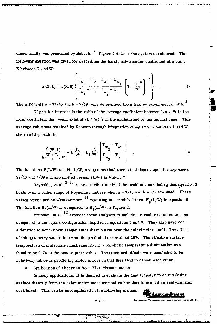
7discontinuitywas presentedby Rubesin. Fig_ire1 definesthe system consioered. The
followingequationwas givenfor describingthe localheat-transfercoefficientat a point
X between L and W:
h (X,L) = h (X,0) Wl o+ w2 Wl 1 La- T T - T ( !Iv
[ w2 ° w2 ° j
The ex_°nents a _-_ _9/_0 and b m_ 7/_9 we_"e determined fr°m _imited e_er_ _ental _ta° _ i_
Of greater interest is the ratio of the average coeff._.ient between L aLd W to the _
localcoefficientthatwould existat (L + W)/2 in the undisturbedor isothermalcase. This -_
average value was obtainedby Rubesin through integrationof equation5 between L and W; i
C
the resultingratiois !
-I11: - T
h (W, L) ,L. [ w2 Wl
W+ L =F_w) +H1¢) - T (6) i
h ('m_-=, 0) Tw 2 o i
The functions F(L/W) and HI(L/W ) are geometrical terms that depend upon the exponents
39/40 and 7/39 and are plotted versus (L/_) in Figure 2. _-9,10
Reynolds, et al. made a further study of the problem, concluding that ,_quation 5 _
holds over a wider range of Reynolds numbers when a = 9/10 and b = 1/9 are used. These b11
values ,.care used by Westkaemper, resulting in a modified term H2(L/W) in equation6.
The function H2(L/W ) is compared to HI(L/W ) in Figure 2.12
Brunner, et al. extended these analyses to include a circular calorimeter, as
compared to the square configuration implied in equations 5 and 6. They also gave con-
sideratton to nonuniform temperature distribution over the calorimeter itself. The effect
of this geometry was to increase the predicted error about 10%. The effective surface
temperature of a circular membrane having a parabolic temperature distribution was
foundtobe 0.75 of the c_ater-pointvalue. The combined effectswere concludedtobe
relativelyminor inpredictingmeter errors inthatthey._endto canceleach other.
2. Application of Theory to Heat-Flux Measurements
In many applications, it is desired _u evaluate the heat transfer to an insulating
surface directly from the calorimeter measurement rather than to evaluRte a heat-transfer
coefficient. This can be accomplished in the follo_.ng manner. (_/_lmcaN-_b_!
-- 7 -- AOVANCtO TICMNOa.O_W _AgO_A_rO_It_i OOVblltON .'
1965013399-019

i ......
J
t
Values of h can be determined from the calorimeter measurement by
= q./(r ° - Tw2 ) (7)
: It is conventional to consider h over both the isothe_.,_.al _oninsulatlng structure and the
isothermal insulating structure (ref. Fit,n_re :t) to be e_ual and defined by
,_ h = qisn/(T° - Tw2) = qisi/('r° - Twl ) (8)
Consequently, theheatfluxto an isothermal (undlsturbed)insulatingstructureis related
toqlsn and the temperature potentialsac_'-vrdingt_)
: = iTo- Twl I _
qisi=h(To-Twl)=qisn{_oo (9)
From equations7 and 8, the ratioofh/h isobtainedas
f_- _ , (10)h qisn
and from equations 7, 8, and 10 the ratio q/qi_i becomes
- q Tw2] (11)qisi qisn
T_.eavailabletheorycan thereforebe used to predictcorrectionsrequired for _'
calorimetermeasurements, provided that:
1) Gas-strea_, surface, and calorimetertemperaturvs are known.
2) The flow in the boundary layer at the surface approximates the flat- r#'
plate flow assumed in the ana!yslv.
3) The distance of the calorimeter from tLe point of boundary-layer
inception is known.
It is unlikely that all of the information above will be accurately known for
typical flight conditions. However, based on available flight data, engineering estimates
o! the required corrections can often be made.
1965013399-020

i
E. _mulatiou Theory
One of the first steps in an evaluation of a heat-flux meter is to ascertain what,
e_actly, it should measure. The measurement that is usually of primary concern is
the net flux to a heated structure. To obtain this measurement, the he_t-flux meter
should indicate the heat transfer that would exist at a test station if the meter were
not present• In practice, of course, it is rarely possible to achieve this goal because
a calorimeter that is placed _n a heated struct,,re disturbs _he thermal characteri_*Jcs
in the immediate vicinity. Since th_ se thermal disturbanr, e:_ introduced by a calorimeter
are often difficult to determine accurately, a practical approach is to 1) minimize the '_
disturbar.ce, 2) recogniz_ its presence as a potential source of error, and 3) attempt to
correct for the errors it introduces, i
F. Calor:meter Calibration _/
•- The foregoing discussion shows how errors in heat-flux measurement are inheren_
in the installation of a calorimeter when the temperature distribution in the heated _laicture
is disturbed. It would, of course, be desirable to est-,blish a laboratory calibration tec_- //
nique that would always ;_ccount for and correct the_e errors. Tbis demand is difficult to
fulfill, however, bec_us_ of the many variables that c;mnot be sufficiently controlJed during
either laborato :y calibration or act_al application of a meter. Furthermore, a valid cali-
bration of this _pe apparently requires a precise knowledge and laboratory simulation of _
i_-flight condi_i ms. Laboratory simulation of such conditions is often highly impractical. _
Although a true single calibration is desirable, its feasibility appears to be question- _
•_b/e. A m_ re practical approach might be to conduct a thorough performance evaluation
of the calorimeter and then coml_are the calibrated-meter output to the actual incident
heating. If a general knowledge exists of the environment to which the meter will be ex- , _
pos_:d, and ff the _curacy of the meter can be exper_.,nentally determined under conditions ,_
d_sigued to simulate the environment, meaningful flight data could be obtained. Information
acquired from a study of this type wou_d permi_ a well grounded evaluation of the expected
accuracy of a given meter in a proposed application. Becausa of the large number o_ "
different n_._ers presently being used and the broad spectrum of heating conditions being
encountered, this information would be extremely useful in selection of the calorimeter t_ t
would best ad_ _t _o a given heating environment and irdicate the heat flux to the instrumented __
:_ ' ' _ " ' _" _ _' _'_ _ _'_ ' _ _' _r _ _ _: _ _ ' ' _ .... _ _' ',
1965013399-021
,_ /' 4"i
structurewith thegreatestaccuracy. With a view to collectingsuch informat_-on.
several popular heat-flux meters were experimentally evaluated. Laboratory heatingapparatus capable of providing convective, radiant, and combined convective-radiaP.¢
_- he_tii_gcondihc,ns was used, inconjunctionwith a varietycf mounti_g structures,toapproximate a wide range ofheatingenvironments.
[
[
[
[
[
[
_' [i L.
_ _0 _ ADVAN_tO TECH_OLOQY LAIORATORI_I OIVIUION
1965013399-022

HEATING APPARATUS
An experimentalprogr;_m was conductedto investigatethe magnitude,ofthe err¢ s
previouslydescribedand to eva!uatetheireffecton currentheat-fluxcalorimeters. The
heatingapparatusutilizedforthisstudy isessentiallyidenticalto thatused duringthe4,5
previous phases ofthe program. Sincethisequipment constitutesan integralpartof
the Phase 3 work, a descriptionof_,heapparatus is repeatedhere.J
The heating apparatus (see schematic, Figure 3) consists essentia"y of the 30-tip
oxyacetylene heating torch and an electrically heated graphite block. The heating-torch
system includes seven manifolded acetylene bottles and a singI_, oxygen bottle, a flow-
meter for each gas to insure close reproducible control of heating rates, solenoid valves
for automatic operation, and throttling valves for fine control of gas flow. The graphite
block is heated by current frolv, a power supply capable of developing 75 kva. This b!.r,ck
is bathed in argon during the heat-up period, and a shutter is opened automatic_l!y i_
conjunction _qth the opening of the gas solenoid valves. The block temperature is moni-
tored and controlled with a I_.eds & Northrup Rayotube and power controller.
Figures 4 and 5 (front and rear view, respectively} show the over-all layout of the
heating appara__,s. The central portion of Figure 4 shows the graphite radiant heater
with water-cooled cover and control Rayotube directly above it. The large slotted stand
provides variable positioning of the torch, which in this photograph is shown in a hori-
zontal position. Positions of the torch other than horxzontai are for convection hvating
only, without the radiatio:, source. On the right is the water-cooled exhaust duct; on
the left is a portion of the instrument panel containing various control switches, throt-
tling valves, and flowmeters.
Figures 6 and 7 are close-up views of _he heating zone. In Figure 7, the water-
cooled cover has been removed from the graphite block. A 0. 125--inch-thick stainless-
steel test plate (described below) is shown in place, recessed into the brick base. During _.
war._up, the underside of ,he radiant heater is covered by a slidi.ng shutter that is actu-
ated by an air cy)inder This shmter is visible in Figure 6.1
The entire test procedure is automated. The oxygen and acetylene solenoid valves
and a solenoid valve controlling air to a pe_.cxl-tg_e cylinder driving the shutter are
operated by a microswitch sequence timer. The oxygen vah, e opens first, followed
-- 11 -- ADVA_CI[O TECHNOLOGY LAmOm_'ro_lES 04Wn00_ [
"_ II " !
1965013399-023
!
closelyby the acetblene vaive. A pilotflame, which isignitedprior to initiationof
the timing sequence, ign:tes ths torch at the instant the acetylene valve opens. Whenboth convective and radiant heating are to be used, the graphite heat,_r is brought to
equilibriumbeforethe tizlingsequence is initiated.Equilibrium is ,determinedvisuallywith _n _ptlcaip)rometer sightedthrough a hole in_the heater cover. The
solenoid valve controlling the shutter-actuating air cyiind_r is opened by _.e timerinconjunction-_ththe ace_.ylenevalve. The resultisessentiallya stepheat input.
The test then proceeds for a predetermined period of time, after which a reversesh,'lt-off sequence occurs.
'I!
[
L
I9
-[ ._mum
L -- _.2 _ ADVANCEO lrEcHNOLOaV LABO_ x_romllgO OIWStON
196,5013399-024
EXPERIMENTAL PROCEDURES
A. Reference Heat-Flux Measurements
In a test program of the t_c described, it is necessary to obtain an e.ppropriate
beat-flux measvrement to which all heat-flux-meter data can be refere,_ced and com-
pared_ This heat flux should be representative of the heat flux to which the instzu-
mented panel is exposed. The underlying theory and. procedure employed in estab-
lishing a reference-calorimeter heat-flux measdrement is presented below.
C_nvective-heating rate to a surface is given by
qc = h (T O - T v) (12)
The heat-transfer coefficient, h, is dependent upon mass flow rate and gas-stream
properties. It can be assumed that h is a constant by maintaining the mass flow rate
Of both the oxygen and the acetylene constant. Maintaining the gas flows constant will
also permit the assumptiov of constant gas temperature, T , since the combustion- O
conditions are invariant. The only remaining variable on the right-hand eide of equa-
tion 12 is the surface temperature, T . The validity of these assumptions is assuredW
by measuringo_gen and acetylene 0ow with precision flowmeters. The meters used ,._
have a 10-inch scale with 100 equal divisions. _ ,Jutgd earlier, each gas line is pro-
vided w_'_ba throttling valTc for fiu,_ adjustme:,t so that _he flo_v can be easily repro-
! duced within 1% of a specified " '7a_ue.
13Radiant-heating rate to a surface is given by
qr = _ a • F (Tr 4 - 4) (13)S r w
The geometrical-shape factor, F, is a constant of the system as is the Stef__u-Boltzm_mn
constant. The surface absorptivity of the plate surface, a s , and the emissivity of the
graphite block, e , will both be about 0.9 ana can be assumed to be constant, since ther
t_.at plate and meters are prel_ared with a special high-absorptivity high-temperature
finish. The radiation-source temperat_lre, Tr, i_ controlled through a feedback to ,*he
power controller from a Rayotube viewing the source. T can therefore al_o be assumedr
constant. The only remaining variable on the right-hand side of equation 13 is, as Jn
equation 12, the surface temperature, T .w
"l_'_ -- _OVAN¢I[O II[¢MNOLO0_" LAmOMATO_I[B 01_'glSI_N
] 9650] 3399-025
!The total heating rate to a surface subject to both convective and radiant heating
l_ is given by
q = qc + qr (14)
ti ,Since, under any set of constant test conditions to be employe.d, equations 13 and 14 are
shown to be functions of T only, q in equation 14 will also be a function of the surfacew
temperature only. Tbis f__ct provides the basis for the method e_ _va_uating the reference
I; heat flux.The first step is to determine the true heating rate to a test pl_.te under a given set
of mass-flow and/or radiant-heating conditions. This is acccmplishe-I by determiuingthe heat stored in a thin standard-:ing plate as a function of time. The slope of the
resulting cu1_e of heat stored versus time is the rate of heat storage. This rate ofs*.orage plus the rate of heat loss from the rear surface of the plate is the true heating
rate. Separate reference calorimeters were fabricated to m_asare either purely radiantor convective and total heating.
! Radiant-Heating Reference MeterThe radiant-heating reference meter consists of a coppe_ slug 0.500 inch in
diameter and 0. 120 inch thick, suspended in a guard plate of the same thickness and2 inches square. The slug is separated from this plate by an air gap 0. 002 inch wide and
_. is held in place by four strips of Constantan foil (0.1" wide ×0. 0003:' '_"...._.._) bridging the
air gap on the back surface. The back surface is insulated with commercially available
Fiberfrax insulation material.A surface coating of Parsons optical black '.;_cquer (absorptivity > 0.99) is air-
brushed on the slug and guard plate, The resulting surface has a deep velvet-black
appearance which is maintained after heating to 1000°F several times. The temperature
: of the measured witl_ Chromel/Alumel 003 inch incopper slug is a thermocouple (0.
diameter) spot-welded to the back cf the slug.
The resultant temperature history is assum_d to be the average slug tempera-
ture. It can be combined with specific heat data fr._m the literature to give the heat
content for the copper slug, The s0ecific heat of _opper can be repre_e.nted by 14'
15
10_5T) '.c = (0. 092 + 1. 142 x Btu/lb-°F (15) _:
-- 14 _ &DV,_I',H=tD 'rlr,_MNOt.OO'_ LAIIOMA'I'O_IlIEJ DtVSlilON
l
1965013399-026

The heat content as a function of temperature is then given by
T
Q = j cdT : (0. 092 T + 0.57 T 2 x 10 -5) BtJ/lb (16)o
The 7alidity of this device can be best demonstrated by the linearity of its
temperature rise under cons.'_t heat-flux condition_ and especially by the slow decay
of the slus _eml)eratu'.'e when the incident heat flux is reduced to zero. A portion of
the cooling period of the radiation reference calorimeter after a typical test is shown
in FiguIe 8. Iu no case did the slug temperatur_ drop at a rate greater that, ½°F/sec,
clearly indicating that durinF the heating lberiods losses are negligible and _11 heat
a_Jscrbed is _.,_Jng stored. Thus the meter consists of an isothermal mass whose heat-
flux measurement represents the true heating rate.
2 Convective- ._ld Tot.al-Hea_ing Reference Meter
! The measurement o_ a reference convective and total heat flux is much more ,.
_ffficult than that for radiation. The reference calorimeter must be free from the un-
certainties commor, to tygical f_Aght-type calorimeters. Since most problems in he_t-
fbax measurements arise from thermal perturbations of one type or another, the refer-
once tot_l calorimeter ,._hoold be designed such that the presence of the sevsor does not
alte _, the heat trsusfer being measured. This can best be done b.v placing a sensor in a
_.herma_!y infinite thin plate such that the sensor does not influence the plate temperature
in aL'I Way. The sensor best suited for this application is axL in-wall or surface thermo-
coupl, plug made of the parent plate material. The pL_.te itself can then be treated as an
• isothermal mass as in a slug-type calorimeter.
The reference convective-total calorimeter chosen was a 1/8-inch-thick plate of
Type 316 stainless steel. (A low-conductivity material was selected to prevent lateral
conduction. ) S.,rface and in-wall temperature s_nsors were made using techniques well
established in the mam_facture of standard ATL temperature sensors (Delta-Couples).
The scnsors are mode by locating the junction of the thermocouple at the desired depth
frov'J the hep,ted surface in a plug of the reference plate _o-tvrial. The instrumented plugs
are then pressed into the reference plate providing a homogeneous system with essentially
no thermal disturbance due to the preser_ce of the _ensors. The plate surface is painted
with Pyromark high-tempera'.ure black pain t. having an absorptivity of approximate;y 0.9.
-- 15 -- AI_VAN¢:i_ TII_¢.HNOLOOV I_,_llo_'ro_elgl C,lV_ON
, '" . "
] 9650 ] 3399-027
/
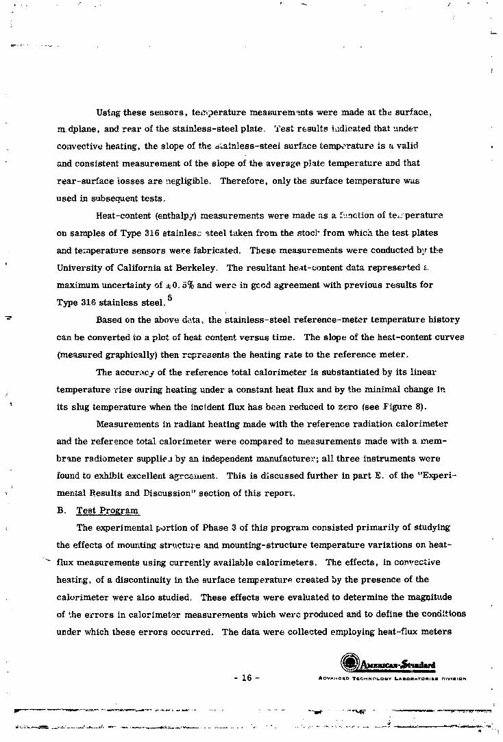
Using these sensors, temperature measurem_mts were made at the surface,
mdplane, and rear of the stainless-steel plate. Test results Lldicated that under
convective heating, the slope of the _ainless-steel surface temp_-rature is a valid
and consistent measurement of the slope of the aver3ge plate temperature and that
rear-surface losses are negligible. Therefore, only the surface temperature was
used in subsequent tests.
Heat-content (enthalp]) measuremen*.s were made as a f::L_ction of te_:perature
on samples of Type 316 stainlesz steel t:;tken from the stoc] _ from which the test plates
and temperature sensors were fabricated. These measurements were conducted b_, the
University of California at Berkeley. The resultant heat-content data represerted a
maximum uncertainty of, 0.5% and were in gccd agreement with previous results for5
Type 316 stainless steel.
_" Based on the above data, the stainless-steel reference-meter temperature history
can be converted l:o a plot of heat content versus time. The slope of the heat-content curves
(measured graphically) then represents the heating rate to the reference meter.
The accuracy of the reference total calorimeter is substantiated by its linear
temperature rise during heating under a constant heat flux and by the minimal change in
; its slug temperature when the incident flux has been reduced to zero (see Figure 8).
Measurements in radiant heating made with the reference radiation calorimeter
and the reference total calorimeter were compared to measurements made with a mem-
brane radiometer supplieJ by an independent manufacturer; all three instruments were
found to exhibit excellent aTz'_e_ment. This is discussed further in part E. of the "Experi-
mental Results and Discussion" section of this report.
B. Test Program
The experimental I_ortion of Phase 3 of this program consisted primarily of studying
the effects of mounting struc._u'e and mounting-structure temperature variations on heat-
" flux measurements using currently available calorimeters. The effects, in convcctlve
heating, of a discontinuity in the surface temperature created by the presence of the
calorimeter were also studied. These effects were evaluated to determine the magnitude
of _he e_rors in calorimeter measurements which were produced and to define the cond[*Aons
u_der which these errors occurred. The data were collected employing heat-flux meters
-- 16 -- AI_VAt_GI[D Td[_._INC_L.OaY LAIOI_TO_IILII nIVllllO_
I
J
" 1
] 9650] 3399-028

2
supplied by NASA_ including various radio :_.',_ers, a copper- and a nickei-s}ur, tot._:
calorimeter, and a membrane total calori.neter. Rad'ant, convective, and combined
m, diant-convective heating were used ii: the tests.
A brief study of the effects of a la] ',e radiant heat input on a gas-temperature
probe was also conducted. The test procedure consisted basically of subjecting a
calorimeter to the test conditions that would bes_ prcrnote the desired effects. For
example, the copper-slug total calorimeter wa_,_,mounted in a h Lgh-couductivity struc-
ture to study cex_ain aspects of cross conduction Identical heat._ng conditions were
then imposed on the appropriate reference meter,
The data collected permitted a critical evaluation of the performance o: a specific
instrument under particular test conditions. Based on the results of meter performance
under the laboratory heating environmen% the applicability of the calorimeter calibration
to the actual application and any required eal_br¢;tion-correction techniques could be es-
tabiished, provided the proposed application sufficiently resembled the test environment.
C. Data Ac,_uisition
The signal from each thermoeouple in a test specimen was amplified and recorded on
a Mirmeapolis-Honeywell Vtsicorder. The Visicorder wa_ calibrated just prior $o each
test. A Leeds & Northrup Model 8662 potentic,meter was used as a voltage referep.ce.
D. Data Reduction _,
The technique used to determine the heat,:ng rate to the reference meters is described
in A. above. The manner in which all other data were reduced depended on the specific
meter tested and on the environmental conditions encountered, A complete descriptio_ of
these data-reduction metnods :'s presented with the experimental results.
- 17 - .o...c.o ..o..o_oov ,..,,o,,..o.,,,. o,v,.,o.
l
Iq I_
1965013399-029

/
EXPERIMENTAL RESULTS AND DISCUSSION
A. .N-123 Copper-Slug Radiometeri...
•_ A schematic of the N-l?3 copper-slug radiometer used for calibration', evaluat_or,
ii, shown in Figure 9. The slug itself is 0.188 inch in diameter, 0.259 inch thick, at, el |!'is instrumented v.'ith Chromel/Alumel wire forming an effective junction at t",e bottom
of the slug. The radiometer is provided with a purge gas flow around t_ ,,' window to keep
its surface free of foreign material. The purge gas is nitrogen run at 7b0 psi to a
: 0.018-inch-diameter surlace in the purge line. This provides the recommended t_ow rate
of approximately 3 scfm.
An eva_uation of the copper-slug radiometer was conducted to determine the effects
of variable mounting conditions and of the purged and unpurged flow conditious on the cali-
bration of the instrument. These tests were performed under radiant heating. A brief
test series was also made to investigate whether tim calibration of the radiometer is
altered by the addition of a large convective heat load to the rad'o::leter flange.
During the tests, the temperature histories at various points of tv.e structure and
meter were recorded. The locations of these temperature measurements are shown in
Figure 9.
Variable mounting-structure conditions were obtained with a 9-7/8': x 9-7/8" × 1/8 :'
copper plate, which was used in both an uncooled and a water cooled-condition. Thus, a
wide range of structural operating temperatures was achieved.
l. Unpurged N-123 Radiometer
The coppe_ ._lug radiomete," was tested whhout purge gas for both the uncooled
and the water-cooled mounting str_oture. The test procedure consisted of subjecting
the radiometer-instrumented structure to a step radiant-heat input. The radiation
reference meter was then exposed to an identical radiant-heat flux. E,,treme care was
taken in placing the slug of the reference meter at the same coordinates relative to the
radiation source as the test radiometer.
The experimental da.*a were collected i:_ the form of temperature histories as
shown in Figures 10 through 13. These data were for radiant-heating zates varying from
7 to 3_ Btu/ft2-sec. Slopes of the radiometer copper-slug temperature were taken at
slug temperatures of 100, 200, 300, 400, 500, and 600°F. These slopes were then
,-18- _('_[i_[" m,I_ ",_ M l'_JI_OVANC(O "r|(:MN{IIL.OQY ILA'J0}MA'I"O,_II_S =l'vlllON
] 9650 ] 3399-030
_ _ ..... .I II_........ _-I .............. I . _ - .... r, I. III II I I._ J__lllm
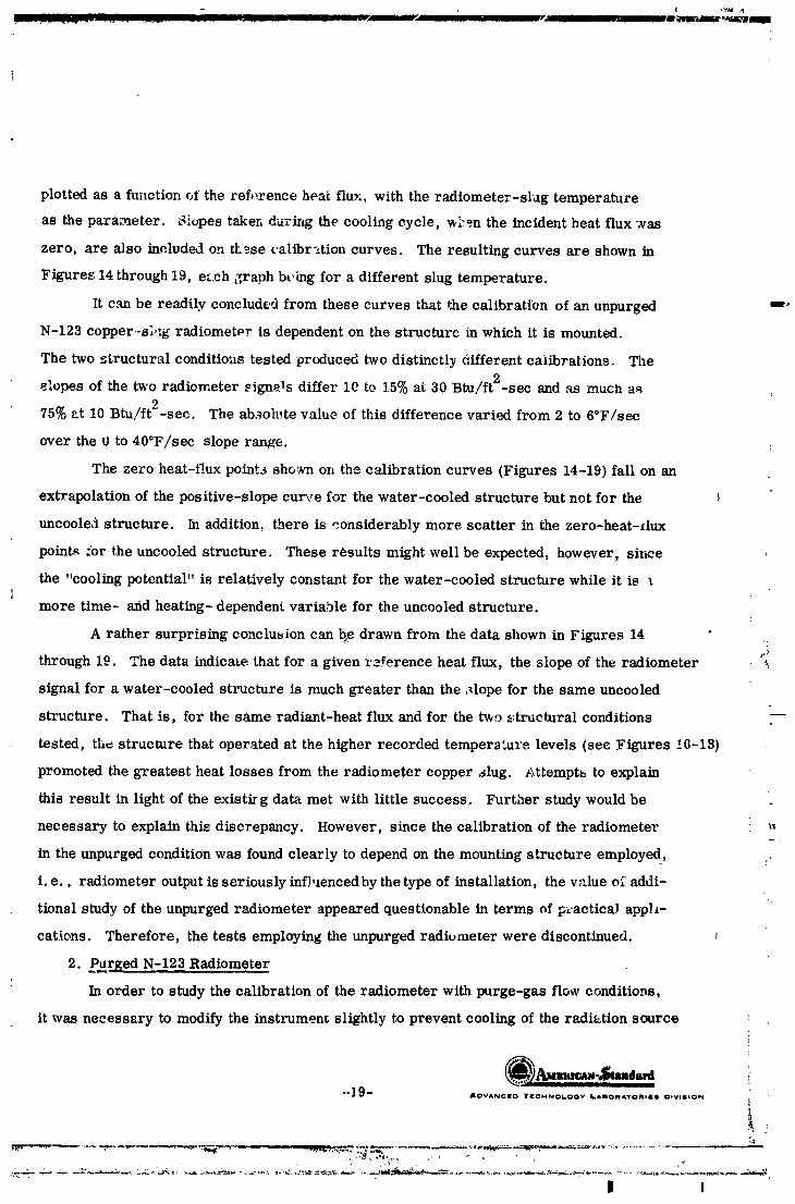
plotted as a function of the ref,,rence heat flur., with the radiometer-slug temperature
as the parameter. Slopes taker, during the cooling cycle, w'.'_m the incident heat flux "zas
zero, are also included on th3se ¢'alibr-_tion curves. The resulting curves are shown in
Figures 14 through 19, e.'ch graph bt'ing for a different slug temperature.
It can be readily concluded from these curves that the calibration of an unpurged _"
N-123 copper.-s;,:g radiometer is dependent on the structure in which it is mounted.
The two _tructural conditions tested produced two distinctly different calibrations. The
elopes of the two radiometer _ign_ls differ lC to 15% at 30 Btu/ft2-sec and _ much as2
75% at 10 Btu/ft -sec. The absolute value of this difference varied from 2 to 6°F/sec
over the 0 to 40°F/sec slope range.
The zero heat-flux point._ sho_vn on the calibration curves (Figures 14-19) fall on an
extrapolation of the positive-slope curve for the water-cooled structure but not for the
uncooled structure. In addition, there is considerably more scatter in the zero-heat-dux
points .'or the uncooled structure. These results might well be expected, however, since
the "cooling potential" is relatively constant for the water-cooled structure while it isi
more time- arid heating- dependent variable for the uncooled structure.
A rather surprising conclusion can b_edrawn from the data shown in Figures 14
through 19. The data indicate that for a given reference heat flux, the slope of the radiometer '_
signal for a water-cooled structure is much greater than the ,_lope for the same uncooled
structure. That is, for the same radiant-heat flux and for the two ,ztructural conditions
tested, th¢ structure that operated at the higher recorded tempera_re levels (see Figures !C-13)
promoted the greatest heat losses from the radiometer copper slug. Attemptb to explain
this result in light of the existirg data met with little success. Further study would be
necessary to explain this discrepancy. However, since the calibration of the radiometer _,
in the unpurged condition was found clearly to depend on the mounting structure employe d, ,/
i. e., radiometer output is seriously infhlencedby the type of installation, the value of addi-
tional study of the unpurged radiometer appeared questionable in terms of p:-acticaJ apph-
cations. "I_erefore, the tests employing the unpurged radiumeter were discontinued.
2. Ptlr_ged N-123 Radiometer
In order to study the calibration of the radiometer with purge-gas f!o_v conditions,
it was necessary to modify the instrumen_ slightly to prevent cooling of the radiution source
"*] 9 _ ADVANCI[O lrI[GMNO6OOW LAmOMATOMI_e DUVUIImION
I I
9650 3399-03

}
I[
by the purge gas Since the radiometer is located only about 1½ inches from the graphite
heaterduringcalibration,the purge gas, under n0rmal operation,would impinge directly
on theheaterelement. This problem was resolwrlby addinga deflectingring(shown in
Ii the sketchbelow),which caused the purge gas toflowoutward along theflange,n_t onto
theheater.
[Mica Ring, Held Down "--"-k /--Thin FoilRing, Spot-Welded to
by Tabs, Deflecting \ // Body, withT_bs to Fold Over
Slightlyunder Flow _ // Mica RingPressure /
|!
The thin mica ring shown above acted as a flexible flow deflector and, at the same time,
permitted most of the incident radiation to pass through it: thus the ring did not alter theheating of the body adjacent to the window.
As previously noted, the purge gas was nitrogen flowing at approximately 3 scfm.Tests were conducted for radiant-heating rates from 9 to 36 Btu/_t2-sec as
measured by the reference calorimeter. The radiometer was mounted in both the water-cooled and the uncooled copper plates previously described. T)oical temperature his--
toriesmeasured duringthesetestsare shown in Figures 20 through23.Again, a calibrationcurve was prepared by plottingthe slopeof theradiometer-
slug temperature as a functionof the laboratoryr,:f2renceheat flux,with the slugtempera-ture as theparameter. The resultsare shown inFigures24through29, each graph being
for a different temperature. These curves can also be compared in Figure 30.Within the range of heat flux and mounting conditions testeu, these curves indicate
that, for a given slug temperature, the N-123 radiometer, when purged, is uot influencedby mounting-structure conditions. It appears, from nnaiysis of the data, that the purge
gas provide_ a relatively constant heat-sink condition which domihates the heat-loss modes.
l --20-- AD_,0_,NCI[CJ TI[C:NNOLO¢3Y lI.AuomA'ro_ll[ll D*V*II*O_
r
I
] 9650 ] 3399-032

It can be seen that the temperatures of the copper prate ar ,' consistently lower with purge gas
than w._hou_, indicating that the purge gas is cooling the entire _ssembly.
The points on the calibration c,,rve taken during c_.'q_alg (a condition of zero inciclenL
hest flux) can be seen to fall on or near the extrapc.latio.n ,.,f -. ca. ve through the positive-
slope points for the uncooled as well as the cooled stzuctu, .,. These cooling points also|
exhibit excellent reproducibility with the zero-heat-flux points determined for the unpurged
radiometer _hen mounted in the watez-cooied s_:._ucture- The,, noticeable scatter of the -"
cooling points in the unpurged tests w,ts rcdaced :rein an average of 2.25°F/see to 0.94*F/see,
apparently because of the relatively censt,:nt cooliug effect of the purge gas. ":_
It should be noted that, for a given slu_ te*_,,:r_t-*',_._ , th,_......,,_]ih,,o_4_.. ,_urve for tb ,_ "
purged radiometer generally fads well within t_e limits of the two calibration curves obtained
with the radiometer in the unp_,rged cnvironm._nt. Fu_-thermore, the calibration curves
for the purged r_.diometer are, in every" case, s_eeper than for the unpurged radiometer
(indicating larger heat losses), giving additional evidence of the cooling effects attributable
to the purge gas. These results further substantiate the dominance of the purge gas as the
parameter most effective in controll_ug cross-conduction heat losses from the slug. That
is, the heat, loss trends remain relutively coustant and independent of the structure tempera-
tures encol,ntered. This result, of com-se, ,u extremely useful in aerospace applications i _
because of the large structural temperature w'.riations involved.
It c.m be concluded from the above tests that the calibration of the radiometer must _ i
include o_,eration with purge flow. It can b ,_ further co ,eluded that unless adve,'se structure II
tee tures are expected in fli6ht, the mounting condition need not be s.eriously considered
in calibration.
3. Combined Radiant-Convective Heating of Pur_ed N-123 Rad'ometer 1.
A brief test series was conducted to determine if the output of the purged N-123 _
radiometer is altered by the addition of a large couvective heat load te the flange. During
the first portion of the test series, combined radiant-convective heating was imposed on
the radiometer mounted in a water-cooled sLructure. For the second portion of the test
series, combined radiant-convective h_ating was to be imposed on the radiometer mounted
in an uncooled structure. However, the second portion was not performed because of r'adio-
meter malfunction (discussed below), Note that during the first portiea oi the test series, the
1 ,
-21-
1965013399-033

.__m
m
potential cooling effect did not lower the flange temperature even though the radiometer--i
- flange was attached to the wate:-cooled structure., That is, the convective heating clearly
-* caused much higher flange temperatures than previously encountered. This fact can be
- rea.ai;y observed in Fig'ares 23. 33, and 34.
i Measurement of the reference heat flu::, under" tb.e aeating conditions described,
- prcser._ted somewhat of a problem because the convective-heating source (an oxyacetylene
•,- flame) adds an additional radiaticn component to the radiation from the graphite heater.
- It was decided, therefore, to me,_sur_ the two radiation components separately and add
-,- these qua"tities to obtain the combined reference radiant-heat flux.
The heat flux from the radiatmn source was measured in the usual manner, usingt
- the laboratory radiation calorimeter. Next, the radiation from the flame was measured.
• Such a measurement, however, requires a radiometer with a window so that convective-
- heating effects can be isolated from radiant-heating effects. It was believed that since the
N-123 radiometer itse!f h,_d been calibrated in the previously described tests, and since vet'y
small heat losses were ob._er_-ed at low radiometer-slug temperatures, the N-123 radiometer
could be used _o measure this radiatmn componerd from the flame by ernploying'the cali-
bration curves at h_md :znd using only low-slug-t¢r,al_,rature data.
Using the above technique for establishing the radimat-heat loads, the radiant-
---_ convcciiv- testing was initiated. Test results indic:_te that the radiation component from the9
flame was indeed si,;'nifieant: it m,_..asured 3 Btu/ft'-sec on a low-flux tcSal heat test and
" 7 Btu./ft2-,'.,et. on a higher flux test. Combined radiant-heat loads from both the flame and
--_1 the radiant source in the two tests were 6 and 11 Btu/ft2-sec. The magnitude of theI[
total heat load from the convective source to the flange was determined with the reference
tota I.calorimeter. Measurements indicated that the total heat load from the flame during
f2- these tests '.,as 18 and 19.5 Btu/.t -sec. respectively.
The results of the first two combined.-heating tests are compared to the original
radiation calibr,_tion curves for the purged radiometers in Figures 31 and 32. Temperature-- W
history data are indicated in Figa_res 33 and 34. i
A_ the conclusion of the second combined-heating test, the radiometer copper-slug
thermocouple b_;came inoperative ,and was not readil3 repairable.
Althou_,h the combined radiant-convective heating data gathered are somewhat
meager, they are encouraging _n that the calibration points fall on the original radiation
--22--At,_'._NCI[O TI[C_C_L.C),I_ i*_e_)RATOI_IEI Dlvtll_ol_
't
1965013399-034

calibration curves for the purged radiometer. These results indicate that, within the
limitations of the test conditions, a convective ioad on the flange will not change the purged-
radiometer calibration obtained for purely radiant-heating conditions.
Another method that provides an excellent substitution for the separately meastured
radiation compol:ents previously discussed involves measuring the combined radiation by
_.he same method that was en'_p{oyed to measure the flame radiation ccmponent, i.e., witn
the slug radiometer :tt low sensor temperature. Then if the radiation component that _ssues
from the graphite hea_.r and passes through the flame is desired, the individually measured
flame component could be subtracted from the eombiped-radiation effects measured by the
radiometer. However, in view of the excellent agreement exhibited by tl_e data in Figures 31
and 32, it was concluded that this approach would indicate the same radiant-heat loads as
those suggested by the separate measurements.
B. Slug-Type Total Calorimeters
The Fenwal copper- and nickel-slug total cal,,rimeters tested were identical in dimensions.
The exposed suriace was 3.5 inches square, consisting of a 2.5-inch-square sensing surface
surrounded by a 0.5-inch bolt flange, as shown in Figure'35.
Due to the popularity of this type of meter, a rather intensive performance evaluation
of the two instru_ents was cm_ducted. The basic purpose of this study was to determine the "-.
extent to which the meter calibrations were influenced by mounting structure, mounting-
structtlre tempar.a_res, and mode of heating. Based on the belief tha; valid calibration
curves could be generated, an ;additional objective was to determine the feasibility of extra-
polating the curves into the zero incident-he:R-flux region (represented by a negative slope
ou the temperature-history curves).
Tests were conducted, for radiant, convective, ard con]bined radiant-convective heating.
All tests employing conv._.ctive heating were pcrform_;d at a single downstream position from
the point of gas-1'low boundary-layer inception.
Two types of mounting structures were investigp.ted. The first type included both water-
cooled and uncooled copper structures. The second type consisted of _t heat-shield panel
f.Rbricated from a stainless-steel frame covered with ½ inch of "M-31" castable high-
temperature insulation material supplied by NASA.
_k
Designated by NASA/George C. Marshall Space Flight Center.
.- _
--9_-- AOVANC_O 3"ECMN_;.O(_V laA_o._A'romle Dtvln_o__m.J
I ' ! !
] 9650 ] 3399-035
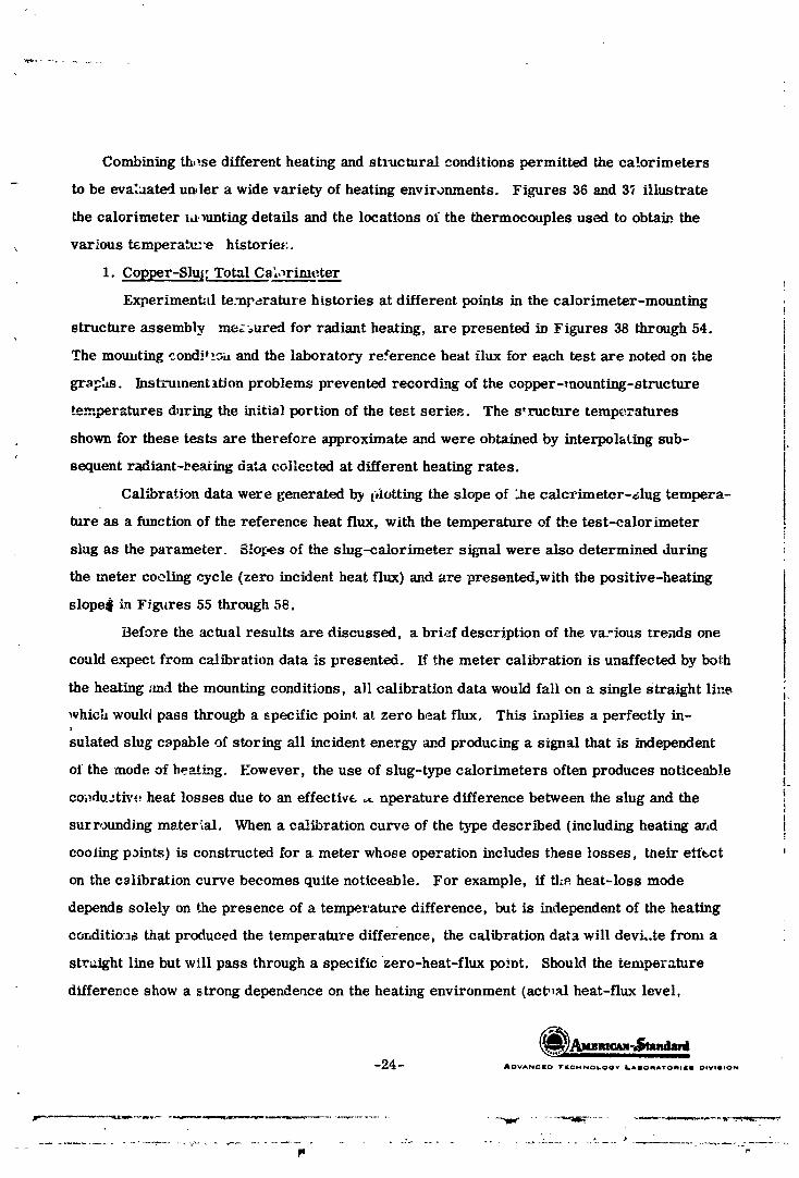
Combining th,:se different heating and stl_ctural conditions permitted the calorimeters
to be eva:_ated under a wide variety of heating environments. Figures 36 and 37 illustrate
the calorimeter ld, mnting details and the locations of the thermocouples used to obtain, the
various tempera_:'e histerie_:.
1. Copper-Slu;: Total Cs_,_rimt:ter
Experimental te.-np_rature histories at different points in the calorimeter-mounting
structure assembly me,_ured for radiant heating, are presented in Figures 38 through 54. '_!
The momiting .ond. _... and the laboratory reference heat flux for each test are noted on the
gr_'m. Instrument ttJon problems prevented recording of the copper-mounting-structure
temperatures d_ring the initial portion of the test seriec. The s*ructure temperatures
shown for these tests are therefore approximate and were obtained by interpohting sub- J.
sequent radiant-l_eating data collected at different heating rates.
Cal_ration data were generated by £,lotting the slope of _he calcrimeter-shg tempera-
ture as a function of the reference heat flux, with the temperature of the test-calorimeter
slug as the parameter. S!o_es of the slug-calorimeter signal were also determined during
the meter cooling cycle (zero incident heat flux) and are presented,with the positive-heating
slope_ in Ffgtlres 55 through 58.
i3efore the actual results are discussed, a brief description of the vEL'ious _rends one
could expect from calibration data is presented. If the meter calibration is unaffected by bolh
the heating _md the mounting conditions, all calibration data would fall on a single Straight line il
which would pass through a _pecific point at zero heat flux. This implies a perfectly in- I
sulated slug c_pable of storing all incident energy and producing a signal that is independentI
of the mode of be_tmg. Eowever, the use of slug--type calorimeters often produces noticeable !
co_du=tiv,.; heat losses due to an effective _ nperature difference between the slug and the i
surrounding material. When a calibration curve of the type described (including heating ar, d I
cooJing p_int._) is constructed for a meter whose operation includes these losses, the.it etf_ct
on the cslibration curve becomes quite noticeable. For example, if the. heat-loss mode
depends solely on t.he presence of a temperatllre difference, but is independent of the heating
conditio:._s that produced the temperature difference, the calibration data will devL.te from a
straight line but will pass through a specific zero-heat-flux po.,,t. Should the temperature
difference show a strong dependence on the heating environment (act_al heat-flux level,
-24- .owNc_o ..c..o.oo. _..o...o.,.. o,v,.,o.
1965013399-036
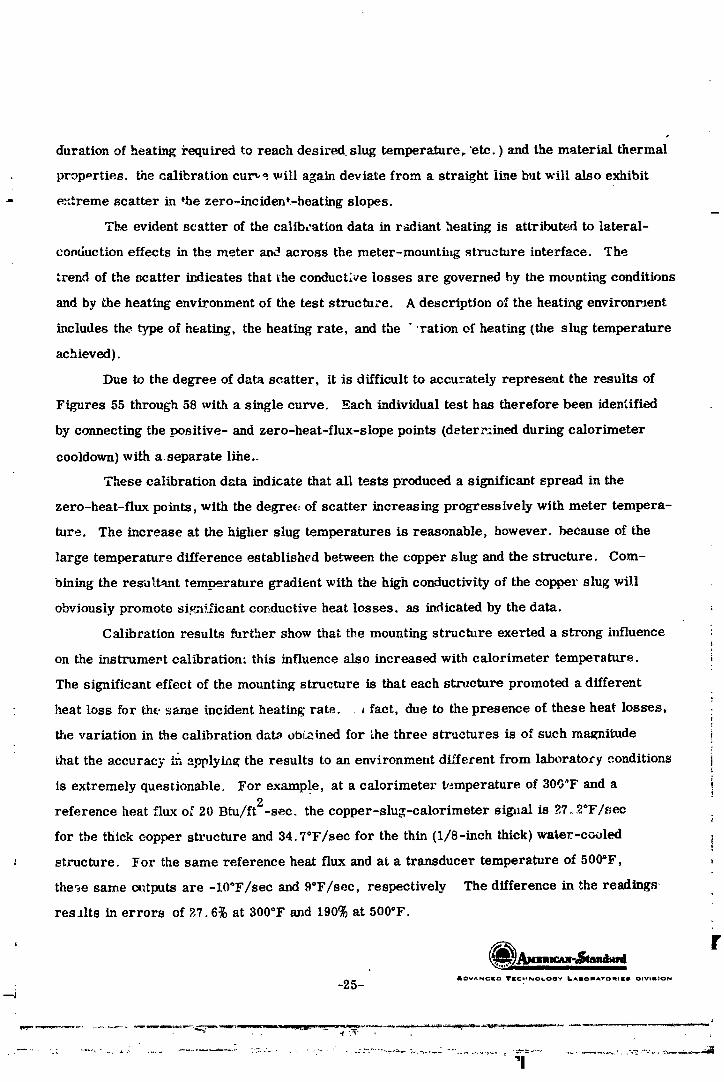
durationof heatingi'equiredtoreach desired slug temperature,"etc.)and the materialthermal
properties,the calibrationcur__.willa_aindeviatefrom a straightlinebut willalsoexhibit
_:treme scatterinthe zero-incident-heatingslopes.
The evidentscatterof thecalibrationdata inr-adiantheatingis attributedtolateral-
conductioneffectsinthe meter an_ across the meter-mounting structureinterface. The
trend of the scatterindicatesthattheconduct_,elossesare governed by the mounting conditions
and by the heatingenvironment of the teststructure. A descriptionof the heatii-lgenvironrJent
includesthe typeof heating,the heatingrate, and the ""rationof heating(theslugtemperature
achieved).
Due tothe degree ofdata scatter,itisdifficultto accuratelyrepresent the resultsof
Figures 55 through58 with a singlecurve. Each individualtesthas thereforebeen identified
by connectingthe positive-and zero-heat-flux-slopepoints(deter_:inedduringcalorimeter
cooldown)with a separate line..
These calibrationdata indicatethatalltestsproduced a significantspread in the
zero-heat-fluxpoints,with thedegree of scatterincreasingprogressivelywith meter tempera-
ture. The increase atthe higherslug temperatures isreasonable, however, because of the
large temperature differenceestablishedbe._weenthe copper slug and the structure. Com-
biningthe resultanttemperature gradientwith the highconductivityofthe copper slug will
obviouslypromote siFn._icantconductiveheatlosses, as indicatedby thedata.
Calibrationresultsfurthershow thatthe mounting structureexerteda strong influence!
on the instrumert calibration: this influence also increased with calorimeter temperature, i
The significant effect of the mounting structure is that each structure promoted a different
• heat lossfor thesame incidentheatinp;rate. _fact,due to thepresence of theseheat losses,:
the variationin the calibrationdat_ obl;_inedfor _he three structuresis ofsuch magnitude i
that the accuracy i_-,applying the results to an environment different from laboratory conditions i
isextremely questionable. For example, at a calorimeter t,_mperatureof 300"F and a i• !
referenceheat fluxof 20 Btu/ft2-sec.the copper-slug-calorimetersig_lalis ?7.2°F/sec
for tbe thickcopper structureand 34.7°F/sec for the thin(i/8-inchthick)water-cooled !
: structure. For the same referenceheat fluxand at a transducer temperature of 500"F,
the_e same c_'_tputsare -10°F/sec and 9°F/sec, respectively The differencein the readings-
resultsinerrors of 2,7.6_at300°F and 190% at 500°F.
rADVe. NCIZD TIC¢_NOt.OO'¢ It.AIIOmATO_IIK_ OIVtlllON
• -_.5---!
"1
1965013399-037

The greatest scatter in the zero-heat-flux points occurs for the thick strucb_re, while
; the least scatter occurs for the thin water-cooled structure. This result appe._.rs reaso_able_
since the t_ick structure could conceivably possess the most variable temperature dLstribution
between tests (dependin_ on the hearing rate), while the thin water-cooled structure would
promote a relatively st.ab_o and constant cooling effect. The d.'_a further indicate that,
generally, the thick copper structure produced the greatest heat losses, even though it did
not operate at the _owest structure temperature.
An effect of the heating environment can be seen by noting that, independent of the
slug temperature, the conduction losses are lower for the lower heating rates during both
heating and cooli_lg portions of the tests. This can be attributed to the fact that when the
test assembly is eyposed to a low heat flux: smaller temperature gradients are developed
due to the combination of the lower heating ra_ and the prolonged duration of heating required
to attain a given slug temperature. This reasoning indicates why the heat losses are the
greatest after the test assembly has t_een hea'_d rapidly.
The trends of lateral-conduction effects can well be anticipated by reviewing the
temperature histories. These curves (Figures 38-54) show that, especially at the higher
slug temperatures, the temperat.tre diflererLces occurring between the main thermocouple
and thermocouple No. 4 can generally produce extreme temperature gradients, which
result in lateral conductzon. Additional insight concerning these effects is possible by
studylng the temperature difference between the center of the transducer slug and the groove
around its edge (thermocoupi_ No. 1). During initial beating, this gradient promotes heat
addition to the slug. However. after sufficient L,eating, the net effect is such that lateral-
conduction losses occur quite readily.
Several attempts were made to achieve a more satis_ing correlation of these test
results. Typical attempts included plotting the ratio of sensible to incident heat flux versus
parameters tryin_ to incorporate structure temperaturevarious dimensionless whil,_ the
h_to a meaningful calorimeter performance curve. Unfortunately, these attempts met with
little success. It was concluded that the heat losses are dependent on temperature gradient_
that are too complex to be described by the point temperature me_urements made during
the tests.
-26- ..ov.,,,¢.o TECHNI_L.OOY ILAIIOIIATOIqlgJI DIVIIIION
1965013399-038
Based on these observations, it has been concluded that data taken with the copper-
slug total calorimeter in a structure of unknown temperature history resulting from an
unknown heating environment cannot be effectively utilized without some additional tempera-
ture information. It cm, be seen that a measurement of only the calorimeter temperature
indicates very little about the structure temperature and the temperature gradients around
the calorimeter that control the heat losses.. A wide variety of loss gradients can exist
at any given calorimeter temperature, and these loss gradients are strongly dependent upon
the structure properties and the heating environment. Because of these results, it appears
necessary to achieve an exact reproduction of the flight-str_ture temperatures and heating _
conditions during the calibratic.n of this type of meter. Since it is often difficult to obtain
this information, tbe obvious limztations and errors introduced by a high-conductivity-slug '°
calorimeter must be accepted.t
2. Nickel-Slug Total Calorimeter }
It is evident from the previous discussion that the nigh conductivity of tbe copper slug i
plays a prominent role in promoting lateral-conffucfibn effects _ It was therefore cons_ered i
possib!e that a meter of identical design I_ut possessing a lower thermal conductivity wodLd i
reduce the heat losses from the calorimeter and thus produce more stable cal_ration _:
results. With this in mind, a nickel-slug calorimeter identical in design (rcf. Figure 35) !_
to the copper-slug unit, was evaluated. 7
a. Mounting-Structure Study
Typical temperature histories aze presented in Figures 59 through 73. The
type of heating and the mounting stm_cture utilized for each test are noted on the graphs. '_
Calibration curves were again constructed and are presen_d in Figures 74 through 81.t
The mounting_structure temperatures that occurred for specific calibration points are J
also shown on these graphs. The calibration data shown for radiant he_ting and the copper- :_
mounting-_tr.mture conditiom_ were collected with the same three coppe_'-mounting-structure ._,:
conditions utilized during the previous copper-slug-calorimeter performance evaluation, i
The results clearly r_how that the previous effect of mounting-structure conditisns t:
on meter calibration has been eliminated through the use of a nickel-slug meter. In addition, i
the scatter in the zero-heat-flux points that was evident for the copper-slug calorimeter li-
was reduced significantly. For e_ample, under the radiant-heating environment, the average 1.
1-27- , ....... , ......... _,.o ................ |:
:?.
1965013399-039

||
zero-heat-flux point scatter for the copper-slug meter is 24. _'F/sec with a maximum of
?|_ 34.8*F; the equivalent scatter for the nickel-slug meter is 3.8°F/r, ec with a maximum of|,-o 4.5°F/sec.
r- The data obtained for the copper mounting structures further indicated '.hat
i._ the nickel-slug calorimeter signal is not influenced by the type of heating, Both convective
and radiantheatingproduced thesame calibrationcurve over the range of testconditions.
_-_ Finally,the zero-heat-fluxpointsdetermined for the convective-heatingenvironment fell
_, well within the range of similar radiant data.Additional testing to determine the influence of a colder mounting structure on
the nickel-slug-calolimeter calibrationwas considered butcould not be justified.The
results of such a study can be aaticipated if one considers the test data obtained to date.
Further cooling of a copper mounting structure will merely result in a greater heat loss-:i
potenti_ at all heat-flux levels, ttowever, since the cooled and uncooled structures already
-_ testedindicatedno effecton calorimetercalibrationover tb_ testedconditions(convection
to the uncooled plate produced temperatures up to ab_,ut 550"F, while radiation to the cooled
plate produced temperatures as low as 2000F), fur_ er cooling of the structure cannot beffi)
:11] expected _o cause any additional effect.
;_,_ The trends in calibration data exhibi by tbc :ickel-siug total calorimeter
when mounted in the M-31--coated heat-shield pJaael are q,,itc _i. ' 1"to those produced by
i_. the copper mounLing structure. For example, the d-_la show th,t_. _mn mounted in M-31
- material, the meter can be calibrated by either radiant, convective, c,r combh-md r_liant-
._- convectiveheating, Eithermode of heatingwillproduce a singlecalibrationcurve for theud
conditionstested.
i'_,_ The zero-heat-flu.,- calibration dam collected for the M-al.-coated panel were12determined only for convective heating, as shown on the calibration curves (Figures 74-81).
f:" These points also show the )east degree of scatter of all the zero-heat_flux data presented.
Since the mounting-structure temperature gradients produced by convevtive heating are
generally more extreme than the gradients resulting from the equivalent radiant heating, andt
since the greatest heat losses would be expected to occur for convective heating, it is
-'7 belier9_l that, for the M-31-coated panel, the zero-heat-flux data presented represent the,+
-* maximvm degree of scatter of any comb_in,tion of convective and radiant heat_g.
_ItOY_l NCID 11rl_Ct.4NOkOG'l_ _iBAm(_ll_A,f._ml[_ll OIVI6#_N
L
] 9650 ] 3399-040

The calibration data alsr, indicate that favorable agreement exists among a_l
zero-heat-flux data collected for t_e nickel-slug calorimeter. Since these _ero-heat--flux
points were determined for extreme variations in mounting-structure _emperature (a very
high- and a very low-conductivity niaterial), coupled with a broad range of different heating
environments, their degree of sca_er suggests that the h_ating environment does not signifi-
cantly affect meter calibration. That is, for a given mounting conditlo_ and slug temperature,
the type of heating, the actual heat-flux level, and the duration of heating necessary to achieve
a specific slug temperature do not exercise sigr.fficant control during the calibration process.
b. Comparison of Copper Mounting 5_ructure and M-31-Coated He_tt-_hield Panel
The calibratton curves for the c_lorimeter mounted in the M-31-coated heat-shield
panel (Figures 74-81) agree quite favorably with the data obtained for the copper structure
up to laboratory reference heating rates of approximately 15 Btu/ft2-sec. The indication
is, there'fore, that for any mode of heating less than 15 Btu/ft2-sec, calibration data for" the
nickel-slug meter will exhibit complete independence of mounting structure. Either a high-
conductivity inateriai possessing a relatively even temperature distribution or an insulating-
type structure with an extremely high surface temperature and large temperature gradient
could be employed _ the mounting structure during calibration. Either of the two described _
conditions and any _ombination of convective-radiant heating (within the limits of the test
conditions) weuld generate identical calibration data.
However, for incident heating rates above 15 Btu/ft2-sec, the calibration results
begin to e_hibit two distinct trends. These trends appear to be independent of the method of
he_ting _.y_dpredominantly determiried by mounting-structure conditions. Since these conditions
utilize two extremes in thermal eonduct_vi_, the deviation present in the calibration data is
attribut_ to conductive hest losses. Th_ slope of the c.alibration curves determined _or
both the copp,gr mouvting structure and the M-.31-eoated panel indicates that heat losses from
the calorimeter are much more prominent for the copper mounting t_ondition. That is, the
slo_x_ for the copper-mounting _ondition increases with heating rate at a noticeably smaller
ra_u _han the slope for the insulating mounting condition. Furthermore, the curve for the
heat-shield panel approximates a straight line, which suggests that the calorimeter heat-loss
effe-7;'s for this mounting condition are relatively constant and minimal,
-29- .ov..¢[o.[G.NO_OO__..o.A_o.,..o,v,.,o.
I
1965013399-041
{
Since the .M-31-coated heat-shield panel developed very high surface temperatures
dui-iug convective heating, Gne might conclude that the absence of heat losses exhibited by
the calibration data is not due to tlte insulating qualities rji the M-31 material but is instead
due to the increase in heat transfer to the meter resulting from the induced surface-temperature
discontinuities (discussed in parts C. and D. of the "Calorimeter-Induced Disturbances" section).
However, the presence, of this effect can be disregarded because of the different types of ["
heating used to define the calibration curves of Figures 74 through 81. Both of the combined
heatL-.g tests (radiant _md convective heating) shown cn the ca!ibration curves are predominantly
radiant heating. The measured combined flux of 22 Btu/ft2-sec resulted from the i.,_dividually
measured compopents, ti, at is, 16 Btu/ft2-sec from the radiation source and 12 Btu/ft2-see
total heating from the convection source; the combined flux of 20 Btu/ft2-sec was the res:,lt2
of an 18 Btu/ft -sec radiant input and a 9 Btu/ft2-sec total heat load from the convective ,_:ource.
These two tests, in conjunction with the purely radiant-heating data, verify that any effect of
a step temperature discontinuiL_, at the meter-structure interface do_s not alter meter outl_]t.
It is noted that the individual heating cL,mponents presented cannot be directly added to give
the combined result. Although this discrepancy could not be fully explained using available
data, its presence does not justify additional testing.
An interesting result can be seen from a comparison of Figures 36 and 37. Early
radiation tgsts {Figures 38-54) were conducted with the mounting structure of Figure 36,
which prevented the presence of large slug-edge temperatures (indicated by the low thermo-
couple No. 4 readings) and therefore suggested the pre,_ence of a high-conductance path for
heat losses. However, all succeeding heating tests used the mounting-structure configuration
shown in Figure 37,which resulted in consistently high slug-edge temperatures in the vicinity
of tlie mounting bolts for _ii _bree t_pes of heating. Since radiant heating on the a')pper-
mounting struct,-re shown in Figure 27 resulted in high temperatures (large thermocouple
No. 4 temperature readings), the role of st_.b-mation heating in maintaining large slug-edge
temperatures is not as important as one might assume for the tested mounting configurations.
In addition, the calibration data from the_e tests indicate th.=_ for the nickel-slug calori-
meter mounted in a copper structure and subjected to radiant heatin_ _reater than 15 Btu/ft2-sec,
._ " the same heat b-sses from the nickel slug occur regardless of the slug-edge te,_:_rature;
i.e., regardle'_s of either of the two mounting methods shown in Figures "36 and 37.
°J_____ !
_JO_ AL_VA_C_.t_ 'Ir_c_NO_.OQ'," L_dOeqAr'OWe)E$ DI_ISe_N [
I ' I
] 9650] 3399-042

Temperature histories presented in Figures 59 through 73 show that structure temperatures
are lower for the M-31--coated panel than for the _oppe. _ structure. This result is attributed
to the significant difference in the thermal conductivit_es of the two materials. Further,
the temperature difference between the ce_.ter and edge of the slug varies from test to _est,
However, for similar heating conditions, this temperature difference is greater for the M-31
panel than for the copper structures, but the, magnib_.de of this dfflerence shows no direct
correlation with the heat losses. The structure temperature shows even less correla.*ion.
It is possible, therei'_re, that the temperatures measured are not really indicative of the true
structural temperature effects.
Although a deviation in the calibration points exists behveen the M-31.-coated
panel and the cop, Jr mounting structures at the higher heating rates, the over-all influence
of this variation n_.d not be of great concern. The calibration points for the M-31-coated
panel clearly a._;_'oach a siugle calibration curve over all ranges of the three types of heating _.
used. If the c_._¢,rimete_ is actually calibrated in a low-conductivity structure, the calibration
can be expect. J to, be quite consistent under any of the three heating modes and valid in a
fight enviroamenL. S_.ould the calorimeter be calibrated in other mounting structures
(similar to the *.ested copper Structures), the calibration will be valid at the lower heat-flux ; :,
levds bu_ raig_t not be applicable at the higher he_t fluxes. Errors of as much as 25 or 30% •
can be recognized at the higher fluxes if flight-type mounting conditions are not simulated
during calibration.
It is of intereL_t to no_e that some of the calibration points at a slug temperature i
of 700°F (ref. Figure 79) _how a slight deviation from their expected values. A typical i •
example concerns the calibration point for the M-31 mounting condition at a convective-
heating rate of 27.2 Btu/ft2-sec. This discrepancy i_ caused by the discontinuous change
in the specific heat of nickel, which ocdurs at the Curie temperature of approxim_t61y b'70®F, !
The result is a sudden change _.' the slope of the slug temperature. _,Lkmg the exact slope
difficult to determine. ._
The above discussion indicates t_at the nickel-slug calorimeter possesses many
features that are desirable for a fligb_ transducer. For example, although calibration i_ i
usually performed under radiar', l_eating, the calibration curves for a given mounting
conditicn are v:_lid when applied to a purely convective-heating environment. This result I
_3_ AOVANCI[O TI[CHNOLO0"¢ li.aliOl_A'rOl_Ji[_J O*Vl_,O,.
_........ ,....._ ................ -,7-......... _,,_ ,_,,,.),,e_;--:;_:,__-.,:,_-;/-_,=.... _.:-=.................................. -
' 11
9650 3399-043
f
is very encouraging because it gives considerable support to the validity of past calibration
and flight measurements employing this type of meter. In _']dition, the results show that
for heat-flux levels below 15 Btu/ft2-sec, calibration of the nickel-slug total calorimeter
mounted in a copper structure undez radiant heating is directly applicable to man- _ero-
dynamic heating condition_, e.g., when the meter is mounted in au insulating structure and
subjected to convective heating.
The _.bflltvof thiscalorimetcrtowithstandthe large variationsin flangecon-
ditionswhile nmintaininga singlecalibrationindicatesthatthedesi_rnincorporatesp'_tra-
meters th_.tare highlyadvantageousto the measurement of convectiveheattransfer. One
of theseparameters appears tobe the thermal conductivityoIthe slug. S-_.e the tempera-
tureat thecenter ofthe slugwas not influencedby thevariationinflangetemperature, the
conductivityofthe slugcan be assumed tobe sufficientlylow. However, t_hemeasur_
/ temperature gradients indicate that a similar design incorporating copper as the slug material
would be subject to considerable conduction effects.
Another parameter of importance is the size of the slug. Although the slugs in
the meters tested are somewhat cumbersome, several advantages are introduced. In addition_
to physically locating the main thermocc.uple far from the edges where large temperature
variations have been observed, the unusually large slug area provides a buffer area against
both thermal and hydrod_/namic boundary-layer effects. In view of the high temperatures
measured around the mounting bolts, it is obvious that serious stn_nation heating effects could
develop. Associated with the s_agnation, flow would be both fluid and thermal turbulence on
the downstream side o[ the bolts. This turbulence occurs on the sensing surface but is apparent-
apparently dampad-oat before reaching the center of the slug. Also, any thermal-boundary-
l_ayer perturbations caused by surface-temperature discontinuities appear to be damped-out.
A smaller slug, however, _ould be expected to exhibit some dependence on tile edge effects.
To summarize _he evaluation of the nickel-slug calorimeter for the test con-
,:litions, it can be concludf.d to be a much better instrument than a copper-slug calorimeter
of the same design. In addition, variation in the structure temperature has not been found
tonoticeablyaffectthe calibration.However, th_d!fferencebetween mounting condltiom_ }
" ina copper plateand inan M-31-coated h_at-shieldpanel does produce _ change incali-
bration. This change, which cannot be di_'ectly attributed to a difference in _tructure I.
_3_'" AOVAN_EO YI[CM_OLOOV L4_O;qArO_II:B DtVlIION
1965013399-044

t_emperatur_, was, however, accompanied by a change iu slug-edge tempe:'atures. The
exact mechanisms of the_e changes were not established.i
Based on these results, it can be concluded that calibration :$enerally should
be carrie_ out with the calorimeter mounted in an M-31-coated he_.t-._hie]d panel when the
calorimeter is to be used in such a mounting. The calibration itself, however, can be per-
formed under radiant or convective heating; either should produce a valh_ set of calibration
curves.
C. C-1118 Membrane Total Calorimeter
The exposed surface of the C-1118 membrane total calorimeter tested consists of a
copper body 0.5 inch in diameter with a 0.2-inch-diameter membrane, as shown Jn Figure 8_
The purpose of this test series was to evaluate the general perform_Lnce of the meter and
: to investigate the effect of a meter-induced surface-temperature d_scontinuity on the measure-
ment of convective heating rates. If the study showed that the surface-temperature discon-
tinuity promoted erroneous structural heating-rate me,_.surements, an investigation of data-
correction techniques would be conducted. Finally, a study was conducted to determine
whether the heat flux to M-31 insulation material is affected by water absorption by the material.
1. Effect of Surface-Temperature Discontinuity
Th_ effect of a surface-temperature discontinuity in measuring convective-heating
ra'_s was studied by mounting the membrane total calorimeter in two the_'mally different
m_teria]_.. The reference test structure, promoting a basically isothermal surface condition,
was a 3/8" × 4" × 12" copper plate. Since the body of the membran_ calorime:_.r was also
made from copper, temperature discontinuities at the +_ustrument-structure interface were i_
essentially elinfinatod, introducing a reference surface conditiot, with no temperature vari-
ation except tha_ across the membrane itself. ,i
The nonisothermal surface condition was induced by the large difference between the
thermal conductivities of the meter copper body and appropriate mounting structures. Two
such noDisothermal mounting structures were fabricated. The ".irst _vas assembled using
commercially available fire bricks. The fire-brick mounting structures tested included
both smooth and rough surfaces to permit investigation of any effect of surface-contour mis-
match. The second nonisothermal mounting condition incorporated an M-31-coated heat-
shield panel identical to the one described in part B. of the "Experimental Results and !i
Discussion" section. The conductivity of the M-3] material is approximately 0.07 Btu/hr-ft_F.
"33-- IDVAN_I£O "IP_CH_LOOY ItAIOIqAT_IIIIIi OIVIIION
+"P'-'_"--'+• "+'++"--'_..,.-,..,,._,,_,- ,.,_.__. = : ,-._,+_ .:,+ _+pp_,_ + ..... ,., +_ _ + _ ++ _ , - ° .... +, _ +,+, ,+,,._, ._+ ,'++++, . +. , ,.... ,:++'++'+,'+_+.,',++"+"++++'+-_,,,+--+ +.+'..'+_..... + .... _ ..... +'+i - + ++++++,+___.+,_+ +.++_ ._..,,,+_+.__,_. + ......_..,_.._.__._+,_
I " !
] 9650 ] 3399-045

ii
The tests perform_d consisted of sequentially imposing a convective heat flux on
' the laboratory total reference calorimeter and on the membrane calorimeter mounted in the
j Lqothermal-surface structure. These vests the_ repeated wide c,/were over a range
incident-heating _ate._. Identical convective-[,eating tests were thon conducted for thet
nonisothermal-surface mounting-structure conditions. During all tests, the reference- !t
m calorimeter sensor and the test-meter sensor were situated in the same coordinate position i
relative to the convection source and were subjected to the same flow starting lengths. !!+
_"_,,._:_ procedur_ insured constancy and repeatability of test conditions. _dditional validation
¢,_ repeatability wa.Q provided by the fine degree with which the gas flow could be controlledt •
and by the excellent reproducibility of the laboratory-reference-calorimeter measurements I
between the isothermal- and the nonisothermal-surface heating tests. Test series were tI
conducted for calorimeter locations of 6, 15, and 31.6 incbes downstream from the point !i
of convective-gas-flow boundary-layer inception in order to compare the theory and data at Ii
different values of L/W (see part D. 1.of "Calorimeter-Induced Disturbances" section), i+
: a. Surface and Free-Stream Gas-T_mpera_re I_ieasurements It
In order to correlate the vest result_ with theoretical predictions, it was necessary I
to measure the surface temperature of both moun_in_ structures and of the calorimeter i
!body, ss well as the free-stream gas temperature. Chromel/Alumel thermocouples were!
used for all surface-temperature measurements. A thermocoupJe was attached to the calori- t
meter body to provide a measurement of the body surface temperature and, in the ._othermal It
case, of _he strv_.ture surface temperatares, since the entire system is made of high- t
i
Iconductivity copper. The low--conductivity structures were instrumeuted with a thermo-|
couple just bt low thei], surface and approximately 0.3 inch upstl,.am from the calorhr '_er- ti
structure interface. Surface-temperat-re measuroments showed excellen_ correlation with i
t"calculatefi values.
Accurate. gas-temperature measurements were, of course, more difficult to
acl'"',ve than. ,,'face-temperature measurement_ because of the extreme temperatures I
er_cot nte, xt; _michiometric temperature for complete combustion of oxygen and acetylene t
is m, ._ _ss c_f 5000°F. Thermocoup]es capable of withstanding these temperatures must
be fabricated from. refractory metals. Such thermocouples, however, e:diiblt very poor
oxidation resistax, ce and can be expected to last for only a matter of seconds at
-_4- AOVANCID TEC;t'(NOLOOY L&IIIORATOR;r*I DIVISIOI_
J,,s ill F-
1965013399-046
temperatures in excess of 3000°F. The free-stream gas temperature was a_sumed to remain
constant for a g,_'ven incident heat flux. Therefore, if a measurement could be made before
t_e thermocouple oxidized away, the reading would be reasonably valid for the entire test.
Thermocouples made from tungsten/tungsten-26% rhenium and platinum/platinum-t0%
rhodium were placed in the free stream through a fire brick in the same coordinate posi-
tion as the membrane total calorimeter. A number of gas-temperature measurements were
made over a wide range of com,ective-heating levels at each location downstream from the
boundary-layer inception point.
An additional problem arises during evaluation of the gas temperature because
of radiation losses from the thermocouple at high temperatures. It is therefore necessary
to correct for these losses. This is accomplished by making a heat balance between convective-
heat input and radiant losses. Such a heat balance requires a knowledge of the heat-transfer
coefficient on the thermocouple wire. The he_t-transfer coefficient can be obtained directly16
from the cesponse time of the thermocouple, which is given by
T =ep_._D (17) ,4h
A _,eat balance on the thermocouple therefore becomes: (
cD 4(T a T. (18) .4_ o - Tt) = _ -- !
If thermocouples of two different sizes are used, it is possible to eliminate ali unknownsl
in equation 18, including e. However, it was found that the resulting computation is extreme'.'}, i
sensitive to very small errors in the measured temperature, causing inconsistent resu;ts.
An emissivity of 0.8 was therefore chosen for the oxidized amgsten, and equation 18 was applied
to each thermocouple outl_ut. Tests were also run using a ceramic-coated thermocouple.
Because of unknowns in properties and variations in diameter, the data were "not as consistent
as the base-wire data but did indicate the same average free-stream gas temperatures.
Typical surface-temperature and gas-temperature histories are presented in
Figures.83 through 86. These data were taken for meter locations of 31.6, 15,and 6 inches
downstrear._ _rom the point of boundary-layer inception. Gas-temperature measureme_t_ _.
performe_l at the 6-inch location resulted in a relatively stable free-stream temperatur_ '_
of 5000°F Varying the gas flow rates, while providing sufficient oxygen for completeI
--35_ AOVANC[O V_¢MNOt.O(_v LABOMA'_'O_*IO _iv_110_
• , J :
] 9650 ] 3399-047

combusti(,n, did nct noticeably affect the readings. However, the magnitude of the gas
temperature varied significantly with the imposed convective heat flux at the 15- and 31.6-
inch locations. This effect was apparently due to radiant and convective energy" lo_ses over
the longer heating lengths.
b. Heating History of Membrane Total Calorimeter
T.vpica2 heating histories obtained with _he membrane total calorimeter for
both isothermal and different nonL,,othermal surface mounting conditions under convective
heating at the different downstream locations are compared to each other and to the reference
measurements in Figures 8 thr,Jugh 90. Thesc curves indicate that during the first several
seconds of heating, when the meter is subjected to r_nonisothermal surface-tempera-h-_re
condition, the calorimeter outI_t is changing. However, as the test progresses, the i
membrane-calorimeter output begins slowly to stabilize. In all ca_'._s, these calorimeter ia
heat-flux measurements f._r the nonisothermal-surface condition.,:, were much larger than the !'
relatively constant heat-flux measurements registered by tile same calorimeter when mounted
in the struc'_ure (copper) that produced the isothermal-surface condition. The repeatability i
of the labora_ry-reference-calorimeter heat-flux measurements for a given convective-heating
rate was well within 3%, thus indicating the consistency and accuracy in repr,'xtuction of heating t
over the isothermal and nonisothermal surfaces. These experimental r-esul_, coupled with
the underlying theory, directly suggest that the noticeably increased output of the small
membrane calorimeter when mounted in the :_onisothermaI structure is a result of the
surface-temperature discontinuity established at the calorimeter-structure interface.
Because of the response time of the system and flame fluctuation at ignition,
stable calorime;_er readings could not be determined for the nonisothermal-surface
mounting condition until approximately 1 second after ignition, as shown'in the heating
histories (Figures 87-90). It should be further recognized that the actual calorimeter signal
was not a smooth curve, as shown in the heating histories, but was a sawtooth-type curve
similar to electrical "noise" _J.gnals. This indicates that the membrane calorimeter, due i
to its extreme sensitivity and short response time, was able to detect the turbulence present
in the flame. Tbese turbulent effects, however, did not alter the over-all heat-flux deter-
ruination or the long-term variations.
It was o."iginally expected that the measurements made with the calorimeter
for the isothermal ,,_uriace condition would agree with the reference measurements. The
] 9650 ] 3399-048

fact that the two measurements disagree is of some concern and is discussed in part D. of
the "Experimental Results and Discussion" section.
c. Effect on Convective Heat-Transfer Coefficient and Heat-Flux Measurements
Presentations showing the eifect of surface-temperature discontinuity on heat-
flux measurements can be made in terms of either heat-transfer coefficients or actual heat
fluxes. The applicable ratios are:
1) h/h. the ratio of the average heat-transfer coefficient at the surface of thecalorimeter to the kcal heat-transfer coefficient at the surface of a_ undis-
turbed structure (this ratio can be compared to the analytical prediction ofequation 6).
2) (t/qis i, the ratio of the heat flux indicated by the calorimeter to the heat fluxat the surface of the undisturbed structure (this ratio defir_s the error inthe calorimeter measurement).
These ratios, discussed earlier, were shown to be represented by:
h _ q (10)h qisn
o= _ - (11)
qisi qisn "T:- Tw 1 "
Values o: q, Twl, and Tw2 weIe selected from experiment_:l records for constant values of
the temperature discontinuity (Twl - Tw2). The corresponding values of qisi' the heat flux
to the isothermal surtace of the copper structure, were' determined for the same value of Tw2.
Thus, q and qisn were available as actual calorir_.eter measurements and h/h and (1/qisi
could be determined experimentally.
Analytical and experimental results ar_ presented in 1:igures 91 through 93 for
the different downstream locations as a function of the heat flux measured by the laboratory
reference calorimeter. Experimental values of the ratio h/h (direct measurements) indicate
that, in the presence of an 800_F temperature discontinmty at the structure--calorimeter
interface and at a 31.6-inch location, the heat-transfer coefficient at the calorimeter surface
was 30 to 50% higher than the coefficient that would exist at the surface of the undi_lurbed|
structure. There ,'_as a comparable increase of 20 to 30% in the heat- transfer coefficmnt at
the 15-inch and 6-inch locations. The ratio h/h tended to decrease at higher heat flux fo"
--37--_DVAN_ _N_y _Am_A_M _ _IVI_I_N
1965013399-049
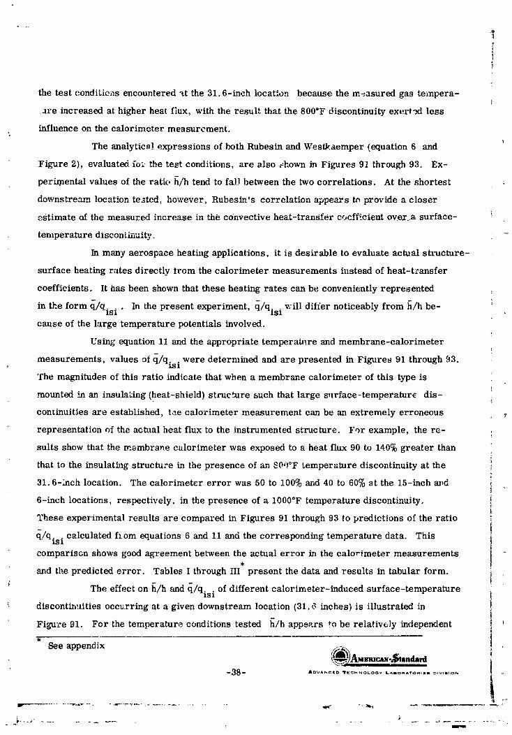
:$
the test conditieas encountered "tt the 31.6-inch location because the measured gas tempera-
_are increased at higher heat flux, with the result that the 800°F discontinuity exert._l less
influence on the calorimeter measurement.
The analytic_! expressions of both Rubesin and Westk.aemper {equation 6 and
Figure 2), evaluated fo_ the test conditions, are also ..:hown in Figures 91 through 93. Ex-
perir/mntal values of the ratio h/h tend to fad between the two correlations. At the shortest
downstream location tested, however, Rubesin's correlation appears tn provide 8 closer
estimate of the measured increase in the convective heat-tranSfer cocff;.cient ov.e.r_a surface-
temperature disconLh-_ui_,.
In many aerospace heating applications, it is desirable to evaluate actus.1 structure-
surface heating rates directly trom the calorimeter measurements instead of heat-transfer
coefficients. It has been shown that these heating rates can be conveniently represented
in the form q/qisi " In the present experiment, q/qisi v;ill differ noticeably from h/h be- '_
cause of the large temperature potentials involved.
Using equation 11 and the appropriate temperature and membrane-calorimeter
measurements, values of q/qisi were determined and are presented in Figures 91 through 93.
The magnitudes of this ratio indicate that when a membrane calorimeter of this type is
mounted in an insulating (heat-shield) structure such that large surface-temperature dis-
continuities are established, tae calorimeter measurement can be an extremely erroneous
representation of the actual heat flux to the instrumented structure. For example, the re-
sults show that the membrane calorimeter was exposed to a heat flux 90 to 140% greater than
that to the insulath_g structure in the presence of an _00°F temperature discontinuity at the
31.6-1rich location. The calorimeter error was 50 to 100% and 40 to 60% _t the 15-inch az_d
6-inch locations, respectively, in the presence of a 1000°F temperature discontinuity.
These experimental results are compared in Figures 91 through 93 to predictions of the ratio
q/qisi calculated f:om equations 6 and 11 and the corresponding temperature data. This
comparisGn shows good agreement between the actual error in the calorimeter measurements
and the predicted error. Tables I through III present the data and results in tabular form. i!
The effect on [l/h and q/qisi of different calorimeter-induced surface-temperature
_- discontinuities occurring at a given downstream location (31, _ inches} is illustrated in
Figure 91, For the temperature conditions tested [l/h appears to be rela_iv6ly independent _
See appendix !
(_AM-alc_-.-_tandard--3B_ AOVA,_,ClCC:, Ir¢_HI_,O_.OOV LAIlORA'VOI_IIES _,VISION
1965013399-050

of different values of the surface-temperature discontinuity. In fact, recog_._.zing the
presence of data scatter, no definite change in experimental values of h/h can be detected,
everL though the surface-temperature discontinuities vary from 340 to 800°F. 2"he predicted
values of h/h also approach this trend. Experimer _.al determinations of q/qisi' however,
were found to be strong!y dependent on the actual magnitude of the surface-temperature
This dependence was also noted for the calculated predictior.s of _l/qis idiscontinuity.
The above-di,_cusscd results exhibit special signific.'mce, since heat-shield
panels are often instrumented with small-diameter membrane calorimeters to determine
the cc,nvective heat-transfer coefficient over the panel surface. This study shows that if
the convective heat-transfer coefficient is determined directly from calorimeter output,
calorimeter surface temperature, and free-stream gas temperature, the resultant coeffi-
cient will be that represented by h in equation 7 (part D. 2., "Calorimeter-Induced Distur-
bances"}. ]t will thus not be the desired v'llue of the convective heat-transfer coefficient
and will be in _rror by the amount h/h as indicated in Figure_ 91 through 93. Of codrse,
if this erroneous convective heat-transfer coefficient is utilized with the gas temperature
'and the heated-structure surface temperature, the resultant heating, rate will exhibit a
similar zrror. If the heating rate to t.he instrumented structure is taken as the direct
output of the calorimeter, without correction for surface-ter.perature-discontinuity effects, '.
then the error will be lar_'e and directly related to (_/qisi as shown in Figures 91 through 93.
Satisfactory agreement between the test data (h/a and _l/qjsi) md the theory
presented (Rubesi,_ _,nd Westkaemper) indicates that error corrections can be estimated •
' for membrane calorimeters if the conditions of the measuremen! arc known. However, it
is doubtful that the necessory information is readily available for the in-flight environments
that promote these errors. Thus, the potential errors in both convective heat-transfer
coefticients and structural heating-rate measurements that can result from calorimeter-
induced sur(ace-temperaturc discontinuities must be recognized.
It should be re_llized that the appartus in the present study does not completely
b:_tisfy th ,_ conditions assumed in the development of the theor- pres,;nted. For the tests
in which tht' calorimeter was located 6 inches downstream, the gas temperature decreas'ed
t
-39- _._.,A3n mv,_q-_ n cLard&DVA_CEO II'ICCHN_LO0V LAmOMA't'OM,_S OtVtAION
1 r I
1965013399-051
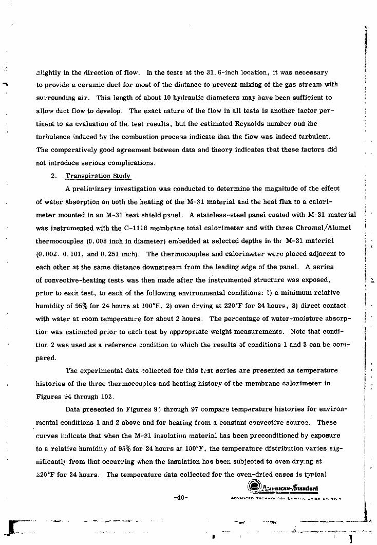
f_*: _lightly in the direction of flow. In the tests at the 31.6-inch location, it was necessary i
i-_ to provide a ceramic duct for most of the di_tance to prevent mixing of the gas stream with
surrounding air. This length of about 10 hydraulic diameters may bare been sufficient to i
allow duct flow to develop. The exact nature of the flow in all tests is another factor per-
tinent to an evaluation of the test results, but the estimated Reynolds number _nd _he
turbulence _mduced by the combustion process indicate that the flow was indeed turbulent.
The comparatively good agreement between data and theory indicates that these factors did
not introduce serious complications.
2. Transpiration Study
A preliminary investigation was conducted to determine the magnitude of the effect
of water absorption on both the heating of the M-31 material and the heat flux to a calori-
meter mounted in an M-31 hea_c shield panel. A stainless-steel panel coated with M-31 material
was instrumented with the C-1118 membrane total calorimeter and with three Chromel/Alumel
thermocouples (0. 008 inch in diameter) embedded at selected depths in th_ M-31 material[
(0. 002. 0. 101, and 0. 251 inch). The thermocouples and calorimeter were placed adjacent to
each other at the same distance downstream from the leading edge of the panel. A series
of convective-heating tests was then made after the instrumented structure was exposed,
prior to each test, to each of the following environmental conditions: 1) a minimum relative
humidity of 95% for 24 hours at 100°F, 2) oven drying at 220°F for 24 hours, 3) direct contact
with water at room temperatu_e for about 2 hours. The percentage of water-moisture absorp-
tior. was estimated prior to each test by appropriate weight measurements. Note that condi-
tior. 2 was used as a reference ,condition to which the results of conditions 1 and 3 can be com-
pared.[
The experimental data collected for this t_.st series are presented as temperature
histories of the three thermocouples and heating history of the membrane calorimeter in :.
Figures 94 through 102.
Data presented in Figures 9_.• through 97 compare temperature histories for environ-
mental conditions 1 and 2 above and for heating from a constant c,gnvective source. These
curves indicate that when the M-31 insulation material has been preconditioned by exposure
to a relative humidity of 95% for 24 hours at 100°F, the temperature, distribution varies sig-
nificantly from that occurring when the insulation has been subjected to oven dry:rig at
_200F for 24 hours, rhe temperature data collected for the oven-dried cases is t]p.ica_
_40-- XDVAI_Ci_ TECM_OL,_OV L,L_r_A,_qI_S Dl_ISI_
, , 1 ] I
] 9650 ] 3399-052

cf temperature histories determined for previous tests and thus verifies the temperature-
measurement procedure. However, the temperature data collected after the insulation was
subjected to the humid environment show that a) the rate of increase of the insulation-
,_ temperature slopes is generally reduced, and b) in certain cases, negative slopes existed.
These results suggest that cooling mechanisms, both evaporative and transpirative, were
occurring in the moistened material c_uring the he-ating test.
Due to reeording-instz'umentation marfimctions, heating rate_ of the M-31 material y
as measured by the C-1118 calorimeter were n)t obtained for the first set of tests (conditions
1 and 2 described above). However, t ae heating-history trends can _ estimated from data
collected for conditions 2 and 3 above; i.e., instr_.'.mented struct_ire subje£ .<1to oven drying
o_q,at 220 .. for 24 hours (reference condition) and to direct con¢.;_c_. _vith water at room temperature
for about 2 hoars. A comparison of the heating hi;3tories measurrJd for these two conditions
is show_ in Figure,_ 98 and 99, The initial decrease in the measured heat flux from a cons_.,_nt
convecti_e-heathlg source further indicates that the presence of water (liquid and/or gaseous)
i,L the M-31 insulation material promotes surface and b_undary-layer cooling that alters the
he,.t flux to the surface and ._othe membrane total ca(orimeter. Temporary reductions of
29% and 25% in the measul ed heating rate due to water absorption are evident in Figures
98 and 99. Because of the large difference in the heat-flux measurements for these two
environmental coT_ditions, three additional heating tests were made with the water-soaked
panel to study further the noticeable cooling effects. The results, show,, in Figures 100
through 102, confirm the previous decreasing heat-flux trends. The temperatu,_'e-histovy
records indicate that the two in-wall thermoc;ouples failed. It was impossible, therefore, to
accurately determine the temperature variatie_ -':ithin the iasulation for the last three tests.
Comparative heating-history data on the oven-dried condition for the three tests (Figures
_00-102) were also unavailable because of the deteriorated condition of the test structure and
the limited time allotted for this portion of _he study.
The importanc_ of this brief transpiration study is that an effect of water absorption
by M-31 heat-shield material on the heat transfer to its surface and to a me.mbrane-
calorimeter surface ):as been measured. This effect is probably clue to gas..transpiration
cooling by the released vapor. A significant variation in this heat .Clux )vas r_cognized between
the wet and dry conditions. L_ fact, temporary reductions of 29% a_rid 25% in the measured
heating rates due to water absorption are e_,ident in Figures 98 and 99, respectiw.ly.
-41- A[ 3ANC:f[I_ YECmmOtOG_ LAmO_A_'_*_ _.S Olv_slo,'_
' _J r
9650 3399-053
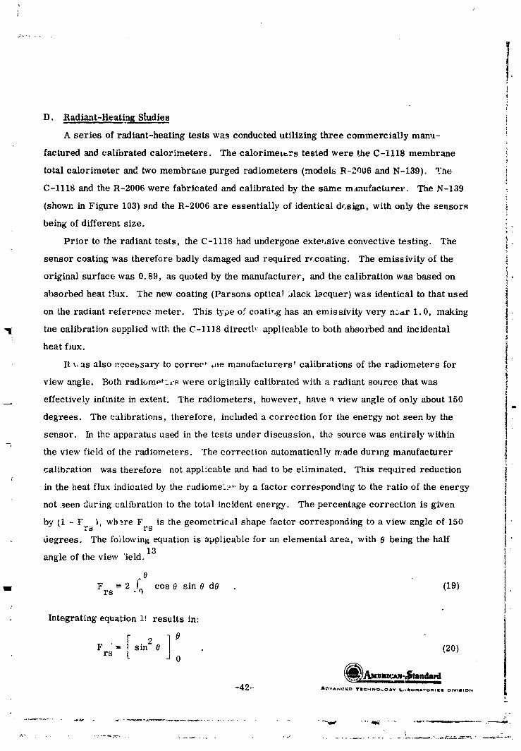
lD. Radiant-HeatingStudies
A seriesofradiant-heatingtestswas conductedutilizingthree commerciaDy manu-
facturedand calibratedcalorimeters. The calorimeters testedwere theC-1118 membrane
total calorimeter and two membrane purged radiometers (models R-2006 and N-139). The
C-1118 and the R-2006 were fabricated and calibrated by the same manufacturer. The N-139
(shown in Figure 103) 8nd the R-2006 are essentially of identical design, with only the seusors!
being of different size.
Prior to the radiant tests, the C-1118 had undergone exteusive convective testing. The
sensor coating was therefore badly damaged and required rccoating. The emissivity of the
original surface was 0.89, as quoted by the manufacturer, and the calibration was based on
absorbed heat flux. The new coating (Parsons optical black lacquer) was identical to that used
on the radiant reference meter. This type of coati,.g has an emissivity very n..,_r 1.0, making _
tne calibration supplied with the C-1118 directb applicable to both absorbed and incidental |
heat flux.
It _. as also necessary to correc t me manufacturers' calibrations of the radiometers for
view angle. Both radi(,mp%rs were originally calibrated with a radiant source that was
effectively inhnite in extent. The radiometers, however, have _ view angle of only about 150ii
degrees. The calibrations, therefore, included a correction for the energy not seen by the •
sensor. In the apparatus used in tbe tests under discussion, the source was entirely within
the view field of the radiometers. The correction automatically made during manufacturer
calibration was therefore not applicable and had to be eliminated. This required reduction
in the heat flux indicated by the radiomeL. _'" by a factor corresponding to the ratio of the ener3_y
not _een during calibration to the total incident energy. The percentage correction is given
by (1 - F _, wb_re F is the geometrical shape factor corresponding to a view angle of 150rs rs
degrees. The followin_ equation is applicable for an elemental area, with 0 being the half13
angle of the view/ield.
O
= 2 _q cos0 sin 0 dO (19)Frs .
IntegratingequationI!,resultsin:
.=[ -0Frs sin 2 0 (20)-J0
"42"" AOVA,'_¢_D TIE¢I_NOI.O,,_V LrxIO_A'roPlllltill I_IVtlION
1965013399-054

For a view field of 15_ degrees, 0 = 75 degrees. Substituting 0 = 75 degrees into
equation 20, the shspe factor is:
F = 0. 933.rs
The correction necessary is 1 - 0. 933 :r 6.7%. Therefore, all radiometer readings
during this vest program were reduced 6.7%.
The test procedure for comparing these three transducers was similar to that
described for convective testing. The graphite resistance-he.,ted source was brought
to an equilibrium temperature, and the temperature, measured by an NBS-traceable
optical pyrometer, was recorded. The laboratory re :erenc_. radiation calorimeter
was placed in the test section, the shutter covering the source was opened, the calorim-
eter signal was recorded, and the shutter was again closed. The C-1118 calorimeter
was then p__aced in the test section and the process repeated. The R-2006 and the N-139
followed in respective order. During the entire test sequence, the source temperature
was monitored and the power to the source adjusted as necessary to provide a stable
temperature. Six tests of this type were run. All test data were good except for
the last test, during which the N-139 lost continuity and no reading was obtained.
In order to compare the readings of the four transducers, the heat flux indicated ,:
by each was plotted against that indicated by the laboratory reference meter during
the same test; the reference-meter output thus appears as a straight line and serves
as abasis of comparison.
The resulting data, with the radiometer readings corrected, are shown in Figure !04.
As indicated, the N-139 agrees with the l_borstory standard within 4% in all but one
test, while the C-1118 and the R-2006 are both considerably higher in all cases. The
latter two calorimeters also exhibit significantly more scatter.
It should be noted that two different mounting structures were employed for the
radiant-heating study of these three calorimeters. Both the N-139 and the R-2006
radiometers were mounted in low-conductivity brick structures, whereas the C-.118
total calorimeter was mounted in a smootb ¼-inch--think copper structure. Because of
the high reflectivity of the copper structure, it reflected more radiation back onto
the radiant source than did the rough surface of the brick structure. One might
cc,_ _lude, therefore, that the noticeably larger output of the C-1118 total calorimeter
--43_ AOVANC[O TCCHNOLOOV II.AmOmA_O_aE*._ _uvlmlO_
:/
f
1965013399-055

I is a measure of this additions! radiation (which has been reflected from the mounting ']L-
structure to the radiant scurce). However, the data for the B,-2006 radiometer,
I which was mounted in the brick structure, indicate that such a conclusion is invalid
because these data show similarly high heating rates and also exhibit better correlationr
| with the C-1118 total calorim :ter than with either the laboratory r_diation reference
, . calorimeter or the N-139 membrane radiometer. These fact,,_ directly suggest that
l the variation in the calorimeter heat-flux measurements that have been detected for
a given radiation-source temperature camuot be correlated solely to differences in
[ the optical properties of _he mounting-structure surfaces but rather is due to a basic
disagreement in the calibration of the actual instruments.
l_ . Because of the close agreement between the laboratory reference meter and the -_
. N-139 calorimeter, the indication is that the error lies in the calibration of both the- C-1118 and the R-2006. This conclusion is further substa._tiated by previous tests
employing bo_h the radiation and the total laboratory-_reference_meters for calibrationstudies of the nickel-slug calorimeter under radiant and convective heating. For
heating rates below 15 Btu/ft2-sec, the two calibrations showed excellent agreementwith one another and with theoretical heat capacities at the lower slug temperatures.
|- These results pro_ ide evidence of the consiBtency between the total and radiant
L reference calorimeters and also substantiate the absolute magnitudes of measured
heat flux. It is believed, therefore, that the reference calorimeters and the N-139purged memb:ane radiometer indicate the correct hea_ing rates. _:/
L
Dur,:ng these tests, another interesting phenomenon was observed. The millivoltsignals from both the N-139 and the R-200_ radiometers during.a typical tesV_ (w_th
both rise and de _ay p_riods included) are shown in Figure 105. These curves indicatethat the response of the radiometers to e_ther a step input or a step cutoff of heat
[ -fluxi_ _ery slow. The N-l_9 appears to have a fa_ter response but still exhibits a
long-term drift before attaining steady state. ']?he decay time for the R-2006 is
particularly slow. The cutoff of heat flux was very nearly a true step change; theshutter closed in less than 0.1 second :
The only apparent explanation for the slow response is that ',he air between thesensor and the window heats up with time, taking heat from the sensing membrane.
i -44.- ANt-,VAN(_ID -irlECHf.mOLC_f]wy 16,AII(.)INIATORtiEi I DIVISION
1965013399-056

The reverse would be true on cooling. The effect does not appear to be a result of
sensor response time, since the membrane is inherently a fast-responding device;
this fast response is seen in the initial rise and decay of the curves. The long-term
upward drift of the signals is not believed to be caused by. changes in source temperature,
since the temperature was monitored at all tirdes a.,'.d since no such drift was observed.
with the C-1118 total calorimeter. In addition, the s|ow dec_ty of the R-2006 indicates
tnat the problem lies i1_the instrument.
A brief test series was also conducted to evaluate the performance of a purged
radiometer possessing a 7-degree view angle. The purpose of the study _ as to investi-
gate the calibration of the instrument _s a function of both its distance from the radiation
source and the magnitude of the purge pressure. Nitrogen gas was used for the purge,
with pressures varied from 0 to 60 psig. The instrument, a photosensitive device,
was mounted in a 0 125-inch-thick stainless-steel structure and was subjected to
radiant heating. •
The radiometer originally evaluated lost continuity during the initial portion of
the test series. A second radiometer was therefore obtained for the study. However,
because of the subsequent dela_ in testing, the original scope of the test plan had to
be reduced. Tile pur_e assembly of the second radiom_.ter was fo, md to be defective
and had to be replaced with components from the original radiometer.1
The data for the second radiometer are presented in the form of transducer-output
histories (a calibration curve was not "ucluded with the second meter), as shown in
Figure 106. The distance between the meter and the rad_gtion source and the gas-
purge pressures for ,_ach test are shown on the graph. Ali tests were conducted for
the same radiant-heating rate corresponding to a block temperature of 2110°F. Except _r
._or the radiometer heating hi_tory _tt the 38.9-inch location, the range of data scatter
is about 7.5%. The results at the 38.9-inch location suggest that the radiation source
did not completely fill the view field of the radiometer, due to incorre,-t positioning
of the radiometer sensor d'.'rectly b,_low the center of the source. Varying the purge
gas (20 to 60 psig) did not alter the meter output at the 16.8-inch lccation. The curves
also indicate that the response of the radiometer to a step input ot heat flux is quite
slow; the instrument exhibited a long-term drift before approaching a re,ati_ ely " +
-45- &OVA._CaD Vl;_oao_v aAmc-.Avo_,_m _'Wn,ON
,,,f,+
++ ++ -, - ...... +- .,-.- +................. ,........... nP,llmm+i , ' ..n .,llmi
1965013399-057

s
°%
!
_. constant heat-flu): measurement. There is also noticeable data scatter for the two tests
at the 16.8-inch l_cation_even though the test conditions were identical. The test results
at the 7.5-inch lo:ation show that when the purge pressure ts constant at 20 psig, the
radiometer output appreaches a relatively constant value. However, increasing the
puzge pressure at thif_ meter location causes a noticeable increase in radiometer output.
.- _ould the purge pressure be reduced to 20 psig. the transducer output would return
to its original me_urement. The data collected for this meter location are somewhat
surprising in chat increasing the purge pressure resulted in a coo/ing effect on the blockand an incre, ased output by the radiometer. Generally, the output of a photosensitive
• _ device increases w_th increasing incident energy. I_owever, these instru_nents canL often exhibit unstable trends, depending un the teml_crature, the incident energy, and
18
the actual properties of the device.E. .%as-Temperature Probe
A brief performance study of a NASA-supplied gas-temperature probe (No. 50M10100)was conductd_d. _tle probe, shown in Fig,_re 107, possesse3 a sensing element composed
of platinum/platinum-10% rhodium thermocouple material. The purpose of this experi-mental study was to investigate the effect of large radiant-heating loads on the gas tempera-
ture indicated by the instrument.The probe was mounted with its longltudin'_l axis normal to both the radiation source
and the direction of gas flow; the sensing _lement was 3.2 inches from the radiationsource. Actual testing consisted of exposing the probe to a free-stream gas tempera-
,r--
ture not exceeding 2500°F; after a steady output was recorded, various radiant-heatinglevels were imposed on the probe. These steps were then 1epeated for different free-
_. stream gas temperatures.The experimental results, recorded in the form of temperature histories, are
presented in Figure 108. The data clearly indicate that the output of the gas-temperature 'probe is readily influenced by radiant-heating effects. That is, when the probe registers
a given gas t_mperature and i_ then subjected to a step radiant-heating input, the probeoutput begins to increase. If the radiant-heating condition is eliminated, the higher
output progressively decreases to the original free-stream gas-temperature measurement.Apparently during total heating, the guard sleeve (see Figure 107) surrounding the
I sensing device is heated by the radiation source and thus reradiates to the thermocouple(_h_-_A_.nmr_tz ¢_ .....
I --46_ AOVAN¢=I[O TEGH_OL.OOY laAOOMATOMII[I OIWlllO_.
i . i i i ii i ii i i ii H , H
1965013399-058

vlement. However, trds he_lng condit,_on diminishes when the radiation source is
removed. A3 would be ex_Jcted, the largest increase in the gas-temperature measure-
ment of the probe due to a &1yen radiant-heating L_vut occurred at the lower ga_ tempera-
tures. For free-stream gas temper_,tures of 921 and 1185°F and radiation-source
temperatures of 1_00 and 2360°F, increases of 4.3 and 9%, respectiveJy, were measured.
However, for the same radiation-source t6_,_eratures and for free-stream gas _mpera-
tures equal to 2196 and 2268°F, increases of only _. 3 and 2%, respectively, were detected.
--47_ B'OVA_CIE'CJ TtCHNOLO_¥ I ',IBO_ _O_fl¢O OIVle_ONJ
i i ,, , H,,,| i ii i i in lUlll
1965013399-059

"-7
CONCLUSIONS
The calorimeter designs evaluated were subject to varying degrees of error in the
measurement of surface he_t flux. 'I"vese errors are attributed to temperature differ-
ences between the meter and the surrounding structure caused by the presence of the
meter itself and arise from 1) cross conduction between the meter and the surroundings:
and 2) in the case of convective heating, perturbation of the boundary layer by the telnpera-
ture discontinuity at _e meter-str_cture inter_ace.
The over-all st_ldy shows that a single cal'bration for a given heat-fl_x meter may not
be applicable for all heating envJ ,'onments and mounting conditions.
A thorough experimental evaluation of heat-flux meters on a htboratory scale has
pro_ed extremely beneficial in establishing their expected accuracies for various installa-
tions and heating conaitions. Conclusions regarding each type of meter studied are pre-
sented bel,_w.
! A. Copper-slug Radiometer (N-12.3)
For a given radiation-source temperature, the output of the N-123 radiometer, when
unpurged, varied significantly and showed a strong dependence on the mounting structure
employed This data scarier and the dependence on mounting s_,rcuture were eliminated
when the r_iometer evaluation in_orporated the purge-gas ilow. A radiometer calibra-
tion to be utilized in flight applications shoald therefore be m._de while operating with
purge gas. The presence of a large convective load on zhe radiorr_:eter did not change the
radiometer calibration obtained for purely _adJant heating.
B. Total Slug Calorimeters
The copper-slug tx_tal calorimeter is strongly influenced by cross-conduction effects
and by the heating environment to which the structure is exposed. A nickel-slug total
calorimeter is su_ :ior to a copper unit because of the significav.t difference in the con-
ductivities of the two calorimeters. Heat-flux measurements with a large nickel calorim-
eter were independent of both the mounting structure and the heating conditions for heating
rates below 15 Btu/'ft2-sec. For heating rates above 15 Btu/ft2-sec, the output of the
calorimeter was deperdent on mounting-structure conditions but independent of the type of
heating. Surface-temperature-.discontinuity effects at the meter-structure interface were
minimized by the large surface area of this calorimeter.
i 48 *" JaDVAN_KD TV:CMN'.._.O_V laABOMA'rO_I_8 ow=s,oN
i ii i ii if i i ill ill ii i
1965013399-060

C. Total Membrane Calorimeter (C-1118)
Results obtained with the C-1118 membrane total calorimeter when mounted in
M-31-coated heat-shield i_'anels show that the output of this instru_,ent can be an ex-
tremely erroneous indication of the convective-he *.ing rate to the structure surface.
For the conditions tested, the heat-transfer coefficient _t the calorimeter surface is
20 to 50% higher than the coefficient that would ,_x_:__.at the surface of the undisturbed
structure, and the calorimeter _.;_dicates heat fluxes 40 to 140% higher than would e._ist
at the surface of the undisturbed structure. These errors result from the _mp. eraturc
discont._nuity introduced or, the surface by the presence of the calorimeter, causing the
convective-heatlng rates to be higher "_hanthose experienced by the parent structure.
Satisfactory agreement between the data and the theory indicates that corrections can
be estimated for membrane-calorimeter measurements if the conditions of the mea_re-
ment are known.
Effects of water absorpttov by M-31 -coated heat-shield material instrumented with "
a membrane calorimeter were studied. These effects were found to alter the heatL-_ rate
to the surface of both the material and the instrument in that temporary reductions of 25%
and 29% were evident in the heating rate measured by the membrane calorimeter.
D. Radiant-HeatingStudie_
Significantscatterinradiant-heatingdaza is evidentbetween the C-1118 membrane
totalcalorimeterand the R-2006 and N-139 membrane radiometers for a given radiation-
source ten_perature. The degree of scatterappears to be independentofthe mounting-
structureopticalpropertiesand ische io a b_sic disagreement inthe techniquesused in
calibratingthe instruments. The outputof thephotosensitive7-degree-view-angle
radiometer, when operated withpurge-gas flow, was dependenton thepurge pressure at
a distanceof 7.5 inchesbetween the radiationsource and the radiometer window. No such
dependence was eviden_atthe largerdistancestested(16.8snd 38.9 inches). However,
the radiometer did exhibitnoticeabledeta scatterbetween successivetests,even though
the testconditionswere iden_,ical.
E. Gas-Temperature Probe
The output of the gas-temperature probe (No. 50M10100) can be influenced by radiant-
heating effects.
49 _ /I'DN'Ar_CIEO I"_.Ct_NOLOGY IL,.AIIO_qA'TO_II_B DIVIBION '_
1965013399-061
RECOMMENDATIONS
Since it is difficult to calibrate a heat-flux transducer for urdversal application,J
it is recommended that laboratory evaluations of current m£ters be continued ill order
to determine their behavior in ,_pecific heating environr:ents. Resulting information can
• _ then be utiliz _d to predict the accuracy of a calorimeter in actual flight applications if
. the e_pected environmentalconditionscan be reasonably estimated.
The practiceo_measuring convectiveheatflux(orconvectiveheat-transfercoeffi-
cients)to a structure at elevated temperature using a rehtively "cold" calorimeter has
been shown to produce results of often dubious value. It is recommende_ that alternative
measurement techniques be investigated for potential elimination of these measurement
errors.
_,.J - _VA_.....ED T_CHNOLO._'_ ll..AmOmATOe, lil DlVlmION
mr
iii [ i i i i i i iii B B _ i B B BBII
1965013399-062
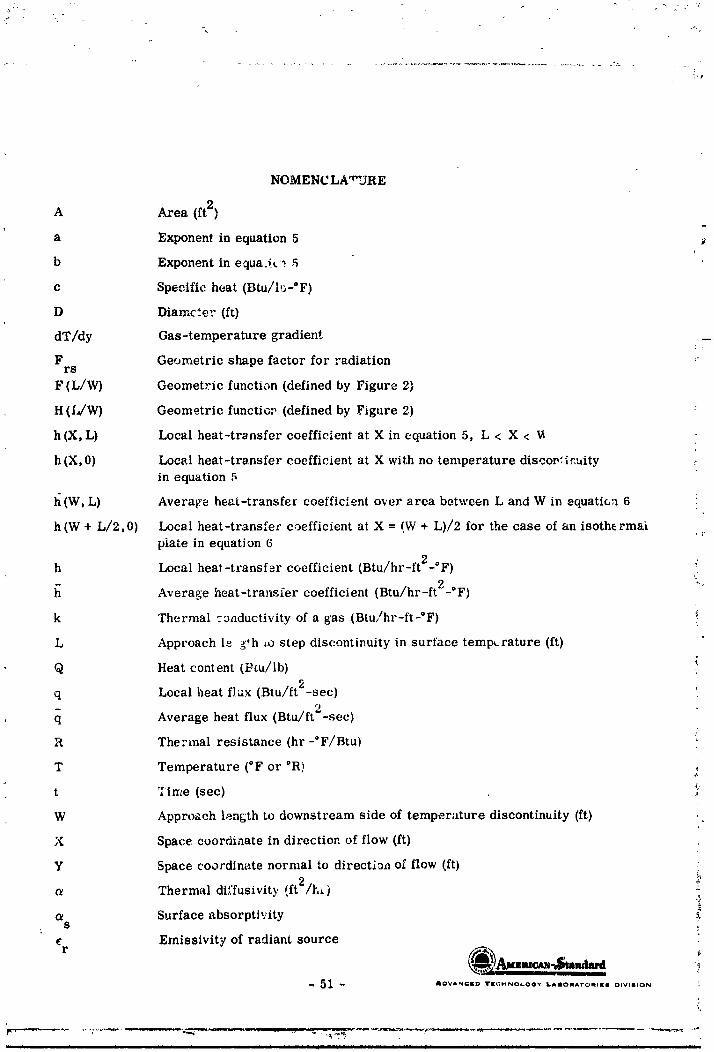
-i
NOMENCLA"URE
A Area (ft2)
a Exponent in equation 5
b Exponent in equa.ic_ ,5
c Specific heat (Btu/h_-°F)
D Dlamc.e. (ft)
dT/dy Gas-temperature gradient
F Geometric shape factor for radiation rrs
F (L/W) Geometric function (defined by Figure 2)
H(IffW) Geometric functior (defined by Figure 2)
h(X, L) Local heat-trvnsfer coefficient at X in equation 5, L < X <
h (X, 0) Local heat-transfer coefficient at X with no temperature disco_:ir_uityin equation 5
l_ (W, L) Average heat-transfer coefficient over area between L and W in equati_u 6 :
h (W + L/2,0) Local heat-transfer coefficient at X = (W + L)/2 for the case of an isothermaiplate in equation 6
h Local heat-transfer coefficient (Btu/hr-ft2-°F)
Average heat-transfer coefficient (Btu/hr-ft2-°F)
k Thermal =3nductivity of a gas (Btu/hr-ft-OF) i
L Approach le _th _o step discontinuity in surface temp_.rature (ft)
Q Heat content (i_m/lb)
q Local i_eat flux (Btu/ft2-sec)
q Average heat flux (Btu/ft"-sec)
R Thermal resistance (hr-°F/Btu)
T Temperature (°F or °R) ,:
t Time (see)
W Approach length to downstream side of temperature discontinuity (ft) ,
X Space coordinate in direction of flow (ft)
Y Space coordinate normal to directk)a of flow (ft)
c_ Thermal diffusivity (ft2/h_) ,_
Surface absorptivity _,S
Emissivity of radiant source
51 _ ADVANCED TI[_:t-INOLOGY LAIIIORA'rOMtlEI DIVII_ON
] 9650 ] 3399-063

!I NOMENCLATURE
(concl+)
# Half angle of radiometer view field (degrees)
p _ensity (Ib/ft 3)
e Stephan-Boltzmann coy. +rant
Response time (sec)
' [ Subscripts
aw Adlabatic wailc Convection
isi Isothermal insulating atructurei_,n Isothermal noninsulating str,_oture
m Calorimetero Free-stream conditions
r Radiations Structure
t Indicated by thermocouplew Wsll surface conditions
1 Upstream of temperature discontinuity2 Downstream from temperature discontinuity
[[[
I
!
RE FERE_CES i -
1. W.H. Giedt, "The Determination of Transient Temperatures and Heat Transfer at a _ iGas-Metal _nterface Applied to a 40-mm G:m Barrel," Jet Propulsion, April 1955.
2. W.H. Giedt and D. L. Rall. "Temperature Measurement in Solids," £-.'oduct
Engineering, 2_99,July 21, 1958.
$. R. Gardon, "±_n I_scrument for the Direct Measurement of Intense Radiation," The
Review of Scienti._ic Instrun_nts, 2__4,No. ,_, May 1953.
4. "Analytical hvestigation of Heat-Flux Meters," Advanced Technology Laboratories, a
[,ivision of Am_.rican-Stan:lard, Final Report, ATL-D-711, 31 October 1961,Contract No. NAS8-1571. _;
5. "Evaluation of Heat-Flux Meters, Phe_e 2 - Experimental Investigation," Advanced
Technology Laboratories, a Division of American-Standard, Final Report, ATL-D-922,31 October 1962, Contract No. NAS8-1571.
6. J.C. Westkaemper, "An Analysis of Slug--Type Calorimeters for Measuring HeatTransfer from Exhaust Gases," R.T.F., ARO, Inc., November 1960, Contract
No. AF 40(600)-800 S/A 11(60-!10).
7. M.W. Rubesin, "The Effect of an Arbitrary Surface-Temperature Variation Along a
Flat Plate on the Con,_ective Heat Transfer in an Incompressible Turbulent Boundary
Layer," NACA TN 2345, 1951.
_. S. Scesa, "Experimental Investigation of Con,vective Heat Transfer to Air from a Flat
Plate with a Stepw_se Discontinuous Surface Temperature," University of California, _-
Berkeley, M. S. Thesis, February 1951.
9. W.C. Reynolds, W. M. Kays, and S. J. Kline, "Heat Transfer in the TurbulentIncompressib:3 Boundary Layer with a Step Wall Temperature Distribution," Stanford
University, Department of Mechanical Engineering, 1957.
10. W.C. Reynolds, W. M. Kays, and S. J. Kline, "A Summary of Experiments onTurbulent Heat Transfer from a Nonisothermal Flat Plate," ASME Paper 59-A-.157,
1959.
11. J.C. Westkaemper, "On the Error in Pl_g-Type Calortmeters Caused by Surface-
Temperature Mismatch," Journal of the Aerospace Sciences, 2_88,No. 11, November 1961.
12. D. Brunner, J. Suddarth, and R. Miller, "Minuteman Calorimeter Technical Evaluation,"
The Boeing Company, Report No. D2-13562, AuguJt 1962.
13. W.H. Giedt, Principles of En_ineerirg_Heat Transfer, New York, D. Van Ncstrand
Company, Inc. (1957), p 372.
14. C. F. Lucks and H. W. Deem, "Thermal Properties of Thirteen Metals," ASTM
Special Technical Publication No. 2_7, February 1958.
15. A. Goldsmith, T.E. Waterman, and H. J. Hirschborn, Handbook of Thermophysical
Properties of Solid Materials, The MacMillan Company, Revised Echtion (1961).
-- 53 -- AOVANCI[O TECi-iNOLO_V II,.amomlA-ro_,tll[ll OIW_lON
,, .... ._,,_,, , , ,,,,,,,,,,, _ _ .................:_. "_•:7_;............ ........ . "- ...................... _' -_
1965013399-065

IRE FERENC ES
(concl.) '_
16. H.S. Csrslaw awl S. C. Jaeger, Conduction of Heat in Solids, London, Oxford
University Press, Second Edition (I759), p 75.
17. ._x Jakob, Heat Transfer, Volume I1, New York, John Wiley and Sons (1957), p 394.
18. I_rt S. Lion, Instrumentation in Scientific Research, New York, McGraw-Hill Book Co.
(1959), p 262. ,_
[
[[[[
-- 54 -- AOVaNC_ TKCHNOaOOY laapj_a'f'o_l[e DIVISION
d
m _ , _ i r i in i ] ill i i[ • _,J i
1965013399-066

l-
• ?
/l/
ILLUSTRATIONS "- /.
/
" ?
! :i
!;
i"
_ _ ADVAN:[O _[¢dNOI-_OY LAIIORA?ORL|| DIVISION
1965013399-067

[
• _ 0
l.-" FM _- F _o
IF. 0 o _. E
L.. _' I m r..) _ W
_ -
i ,I_. i _l IHI I_
L I_ =_._! I" "-o
" --L I( ,-_ := u _ ,-i•,'_--'U"_ , - I_ r = 0 :.
/ I, ? _oI/ / ,...,S ¢'
!._ !_, I _.-._ .."J_ I/ , L*pmI I'_" :_< .c _ lu
I i, , o,_L.. [/ I _, .,a Wi- ,i_ I "" ".__
....... .*_'
• IU
I I _ .®
,_. "---l'--_ --T "__"
I :S / / I I _- ,,,_
/ _., I J_ k ","_ k
! ! _-- LLLj. _.oo..l :
4OO6
1965013399-068
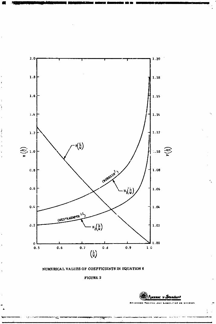
U .q__ ....... n _ I _1 mmnnumm _ t ,-, _
2.0 ' ! I I I I. 20
1.8 I. 18
1.6 - I.I_
1.2 1.12-;
0.8 1.08
NUMERICAL VALUES OF COEFFICIENTS IN EQUATION 6
FIGURE
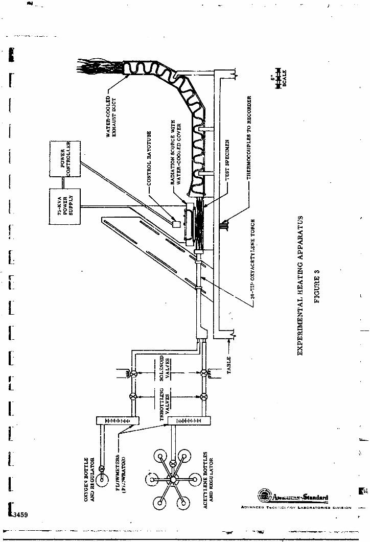
-jl i i i ] i r Jl i 7_ li i I II Irl II I r I I J
1965013399-070
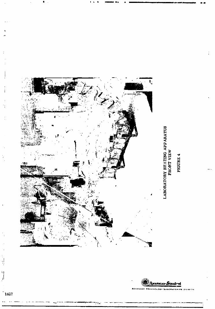
II Ill
ADVANCEt_ I"IrCHNO_.OGV LABORA'rO_IEI OlVIIII':_N
1_27
ii - ,
1965013399-071
r ..., i i i i i ul i ii i luuull i u ul
1965013399-072

|
L
i
" ...... ii i ii F I I Ir |
1965013399-073
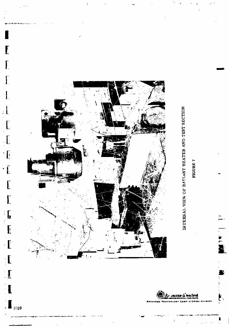
1965013399-074

/l'OV,IN_|_ _I_WNOGOGY I'-_,_O_ATO_I_| OIVI|ION
3755
i ii ii i iii i
1965013399-075


I "%W-- I I Ill [
................ ,..... _IR .++_- , r +
i.
I!(
' ........ IZ| l ! I I I
! °[ ao_Z
I + +i__
I !+km
| _)kd
!i . .
8 oo oo 8 8 oo oo ++++ ,
!! .
3090
__ I i iiiii iiii i ii llll i i i i i,i IIId i i i i
1965013399-078

1965013399-079

i

lql !I11 n n m u m n m m • _ m_i • m m •
0
<
_o ' \
_,_ + _ o_,. .-- _
i"
" \z
I
I I I I I I I I I ' ,"
_,,,m.4;md,,dJ_-DVA, '¢((D I_I[_,;I,¢NO_,_)Q¥ L&mONS_,TOIOlIO OIVIIII|ON
3768
p. ij r i in i i n i n iii iii ilun nnlnn. ..................... " '
1965013399-081
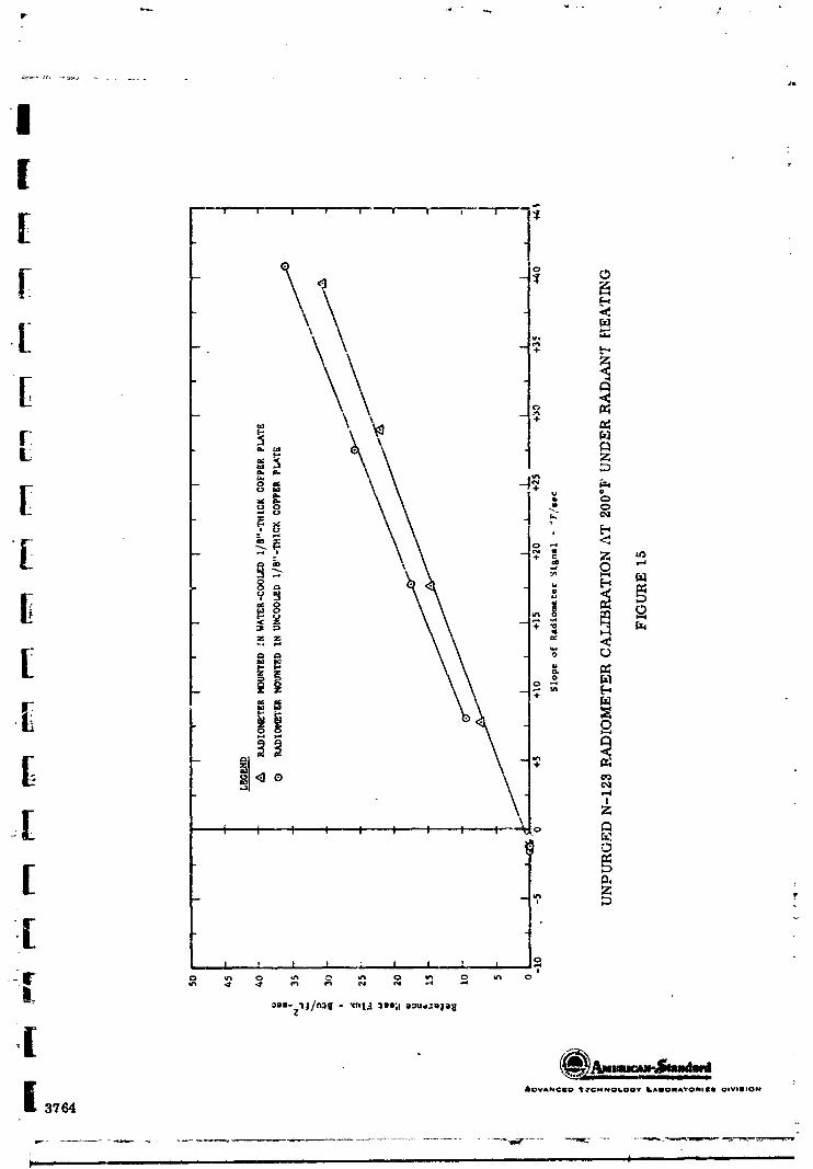

• ! u ! | • • ! i i _
__ n i , _ I , I i ....l _ I!
3765
1965013399-083
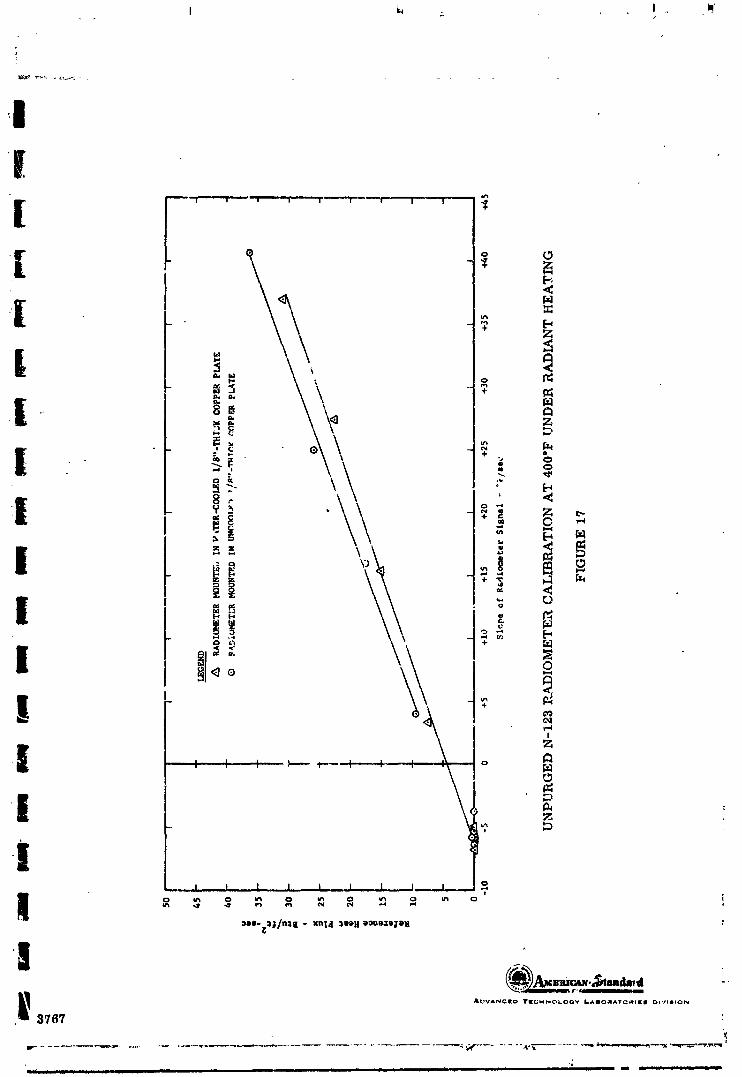
I i_ I •iq/
II
_ii | ! _ _ m l ! ! ! | !
.[ o
[ -I _- ¥ E_
_ °
u _
l } • o
O,1
!
L-!! ,
3767 '.
O_l_ ii ................. I ] _i i i " I " " i i I I : I ' -- It _i -- i L /]L I _-- --_
1965013399-084
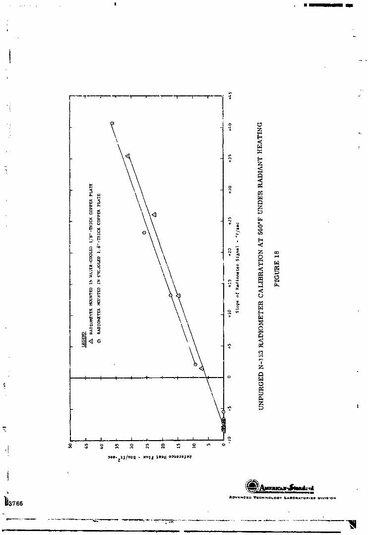
m • [ I
\ <
+ z
i °_, ,
._._
4I ""I I I I ! I o
T
! ! I ,, I , ! _ I I I o
,!
i '
_3766 "o,,,,.c,o,.. ....... ,.,.o,,,,,o........ .o,,
1965013399-085
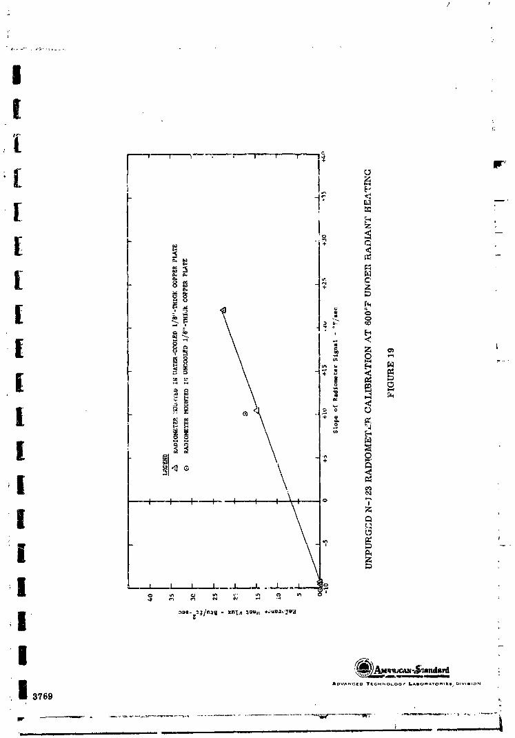
i!
f..
[ , =
=. _]
( =_,__ I _ '__, - o
_. _ _ ,u ,,_
-_ =
o %1
: a 1 \
-, , ,-...+- _ : : ,_' °I °r.,_
,d'
_ dlu_.umr,_umuuup_
I &OVANC[D I"ILCMNO_.O0¢ LADOAATOmtEIP _IVlmION_, 3769 ,.
'u -- ....... . ...... - .......... i1._u _ iii i i n n . n .....
1965013399-086

•"-'_ ...--.,--.----____ , ,-- , ,. , ..... ....
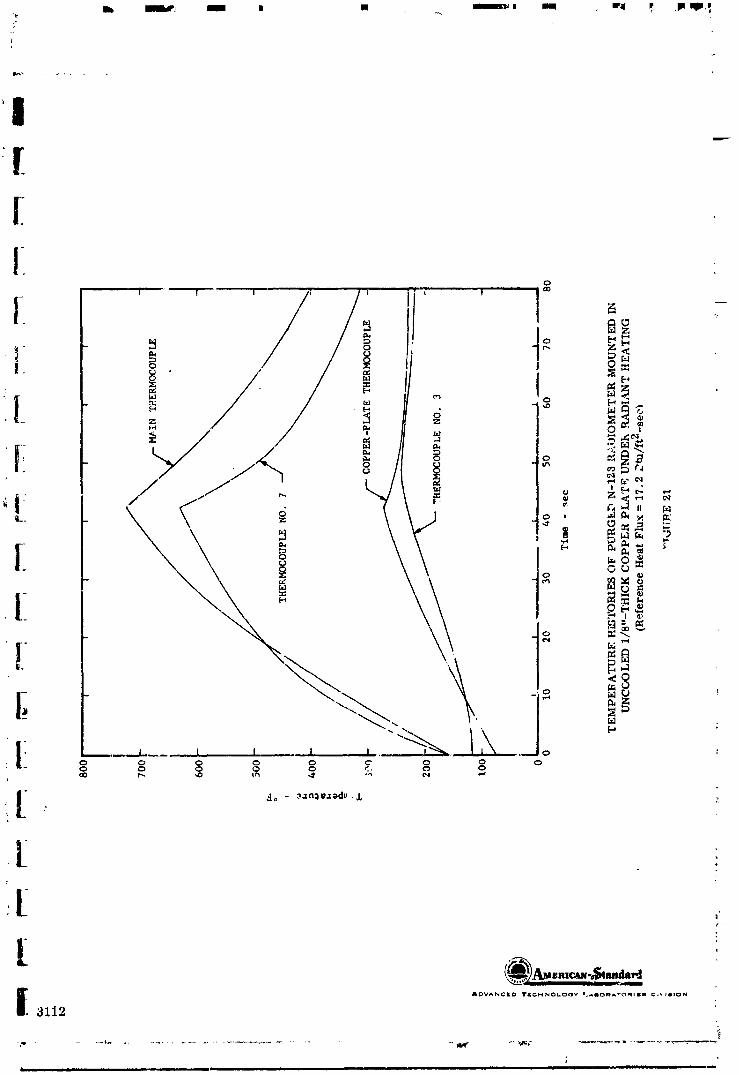
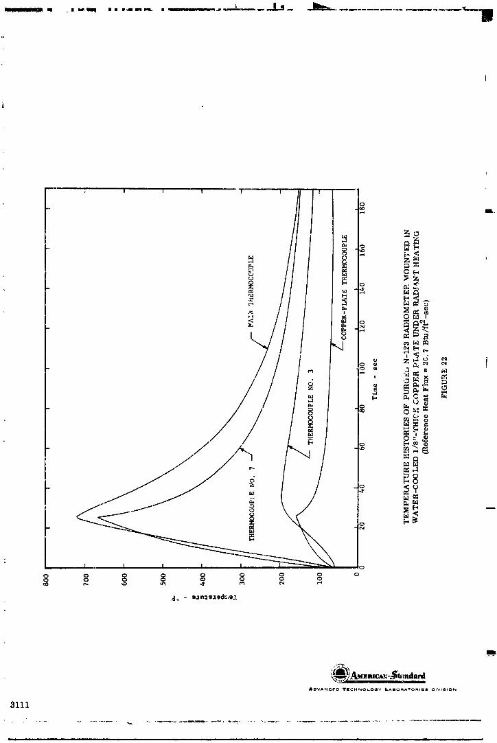
&DVANCFO "IrlIcH,_OI-O_I',' I.AIIom,_"rOmtll[ll r_t'4_lltON
3111
mr m m m mHnnmn,m n m in n|l m IIn H|
1965013399-089

HI i i i [] i | II _/i_a '_ .... . _' "-_ ....... | i_
1
|!
0
0 ,._
_Zo M
_ g
<
_ u%lz
¢7)_ U
-_ _ 0
/ | m _1
° ;
|
I_rV_NCEO _rlCMNOL. OG', _,_mORATORIF_ _IVI_I_N
3110 '-
I
1965013399-090


\ +
<
o ,,-
z
_o -_
, , <_ _ _
0
_o F-
_J
--'_,-- ' I _ -I 0 I o
J
I _ I _ I a I I _ _'_o
,,7
liT,,,
II_VAN_O 'IrlIcM_WOLOGy I._ll_lqA_Omll£11 _IVIII_ON
3772
,j
....... '- - Ul- qm.... _ ...................... "
1965013399-092

I I '_' I i i , .._oi
I_ _'OS'_ l],/n'_l - xnl: .:Zeal; a_uala..lall
_.-_,
3773
1965013399-093
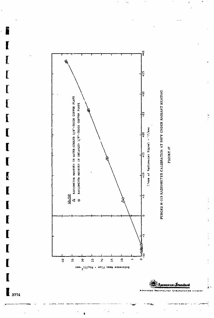
/
|
1965013399-094

0
=' .J I I I I I I I "_
o r2-
_ _ <
, _j ".-
,d__ o_. _
:3 _ _ _ 0
-o ,-.]z z i0
8_
_1- .,,, x _
_,<3 7
5:
_-'F" o _ :
,,;,,
_;_8- :l.t/n:18 - xn_.:l :lg;)_ ;)_u;).lt;_;),_
&OVAN¢I[_ T_[C_O_O_V La_OMATOm[m OlV)I_ON
480 i
' l "r ' 'r "_-
1965013399-095
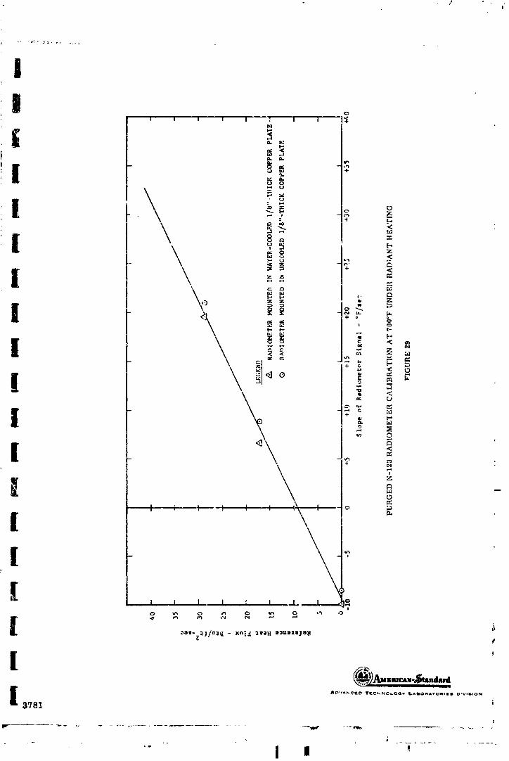
ii o
U 0
"-_ _ z
1_ z _.
z z _
. t, c'_
_ • z
< _gg _ _
M
o
l °<
! °I l _ -I I t I'\
I \
[ @_....._._3781 i
" [ I '
] 9650 ] 3399-096

o
o _ o _ o _ o _ o'
|
3783
!
] 965013399-097

1
Io
[
[ I _ "+ N
_ Z
I-'
• _lll _ 0
_- _,o o, _.< , _ -
o[-,o p< _<
[ ,0 W OI
l.: ' _ "r4 ,=4
_- _e_. _,.;zr.:l R - xnl4 2WaH e_ue_e;a_l.)O_- 3j/n3_ - xrit,:l 31_Oh O:)UOJ.OJO_I
3999 :_,,
] 9650 ] 3399-098

,_ . . ,....t _...-___,_.._, . _ "_""'_'_"/f
/ _
Z
L _ " a :=_ ,._ _: , ,-, ;>
N , >
,W
- Oz- ;_
gg
M
I I I , I I I I I %_h_.--_ o0 0 0 0 0 0 0
:TI
AI_V_,_I(O T_'CHNOLO_ _DORATO_if. il DIVISION
"_ ;_108
F
lI
] 9650 ] 3399-099
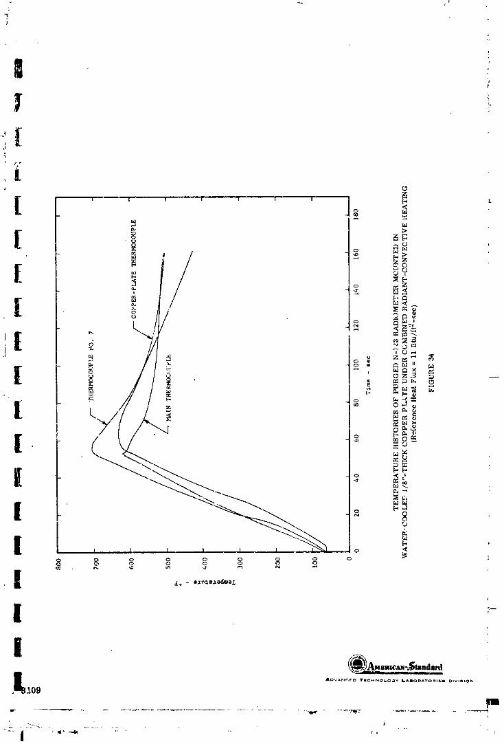

__---2.5" _ _ HOUNTIKGBOLTS
. (TYPICAL) T_ISULATIONm
oo6,___0.03I
] L_ o.12"i
+ .... _ _-_
YSURFACE i Z-- THER_K)COUPLE jUNCTION
BLACKENr:D 0.05" BELOW SURFACE
DIMENSIONS OF FENWAL COPPER- AND _YICKEL-SLUG TOTAL CAIL)RIMETERS
FIGUR E 35
_._2_./_,alc-,_",'sh_la_d__a_IslADVAN'=[[3 T$CHNOt oov LAiiOR _TO_ {')LVIS,0N
"461.
1965013399-101

|I
I
III|
S cm,_ S:RUCrU_EI / /--- THERMOCOL','1_ENO. -_ I
,_.(..._..._.. / . /f-- _m .,m.locorF=_I _ _ ='-__'_'_j .....,.. ii//, +/11//////////;7//7
l +o,,_,++++_+_+_/_, /+L..,............_....=ThEmOcovPt.F. /
i L
[MOUNTING COND£TION AND THERMOCOUPLE LOCATION FOR RADIANT-t:EATING TESTS
ON FENWALI, COPPER-SLUG "tOTAL C,\L£)RIMLTER AND EARI Y RADIANT-HEATING TESTS
ON FENWAL NICKEL-SLUG TOTAL CALt)I_IMETER
FIGURE 36
i!
g
| "
Emr._N-_,_landmd
I &{3VANCED Ir_'cHNoLOGy /_mOF_ATOnlE_ OIVISION ;399& _'_
II _ +', , - • - ' °. -'.................... _i.+_ - +,_p,.. _+ .... _, ...... rl
,+
+,
1965013399-102

I
IS MOUNTED IN M-31 I:EAT SHIELD _ \ ,
\ •"_"_/..z.x.'zu,z.x'z.x'_,.'_
x_,_3 1"1 ...............,,......__ L THEI_OUPLE NO. 1 _ •/
pCOPPER PLATE SECTION A-A : I
|
--.._i,,_;s._E_ ,x . ,",, ;,/,,×,z,z,/,,i4.,,_P,,_
/ STRUC TU RE °I EMPEeATU RE TH ERMC_COUPLE
_THERMO'POUPLE ,I0, I. ,_MAIN THEI_MO_OUPLE
1SECTION B-B i
_' I_IOUNTING CONDITION AND THERMOCOUPLE LOCA'IIONFOR FENWAL NICKEL-SLUG TOTAL CALORIMETER MOUNTED IN
i 1/8"-THICK COPPER PLATE AND IN M-31 ttEAT-SHIELD MATERIAL
FIGURE 37
' ,_mc_t.s andard
4005
.............. "_ - -m
] 9650] 3399-] 03

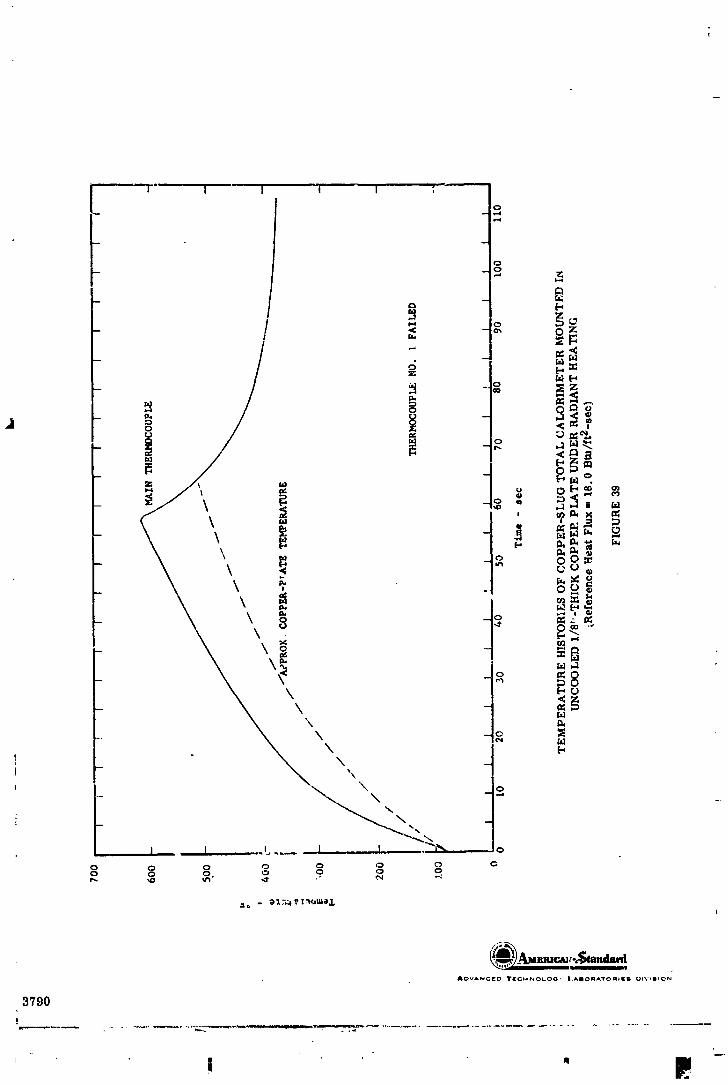
AOV*NCEO Ir[cH_'_ot.o0, t._llomAvom,|_ UIV*_ION
3"/90
!
1965013399-105


AO_*'_,NCED 'IrlEG_OL.OC_W _A|O_A'_'OI_II_L| 01VlIIICJN
3792
1965013399-107


(_A__BRICAN _'" ----
J_oV,'l,N,-'l[{:) slril_ChINO(,-OOY LAilORA'_'O_II;{I I_VIIIOIN
3794
......................... i _%. , .......... .
1965013399-109

Ii!
[ _ _oo" ,-1
"-" Z_N
, t :_[..,
-" --r-. [-, M ti I@[,-*
[ ' ._ _._
t ! "°i - Ii D] o__=_i
! - __0
I \t ,, : _'
I ° o o o o o o
i AI_VANC¢O ?iCHNO_.O_Y I-Nit t A_OIllO DIVIIlON3796
D
" ' _V I
1965013399-110


![[
o
I '. I I _o
[ __ _ o _
o _
_ e
,_M i_ o _
.4- ,_ T [.;r..]:
M
, , I I I o .
[
_[_VANClEO TECHNOLOgy LAI_Q_IAT*;_IIE8 _IVII_,ION3'798
1965013399-112

i i
1965013399-113
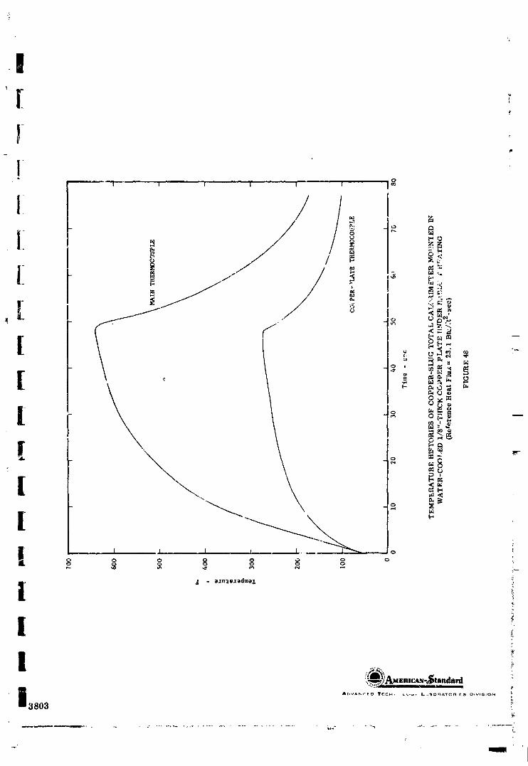
I1
1I
1_ °,'<l zo
I _ _
o
0 0 0 0 0 ,,_ 0 0
i-,,.
'tt
I !_AM E RICA.N "_| lllldard
3803
1965013399-114
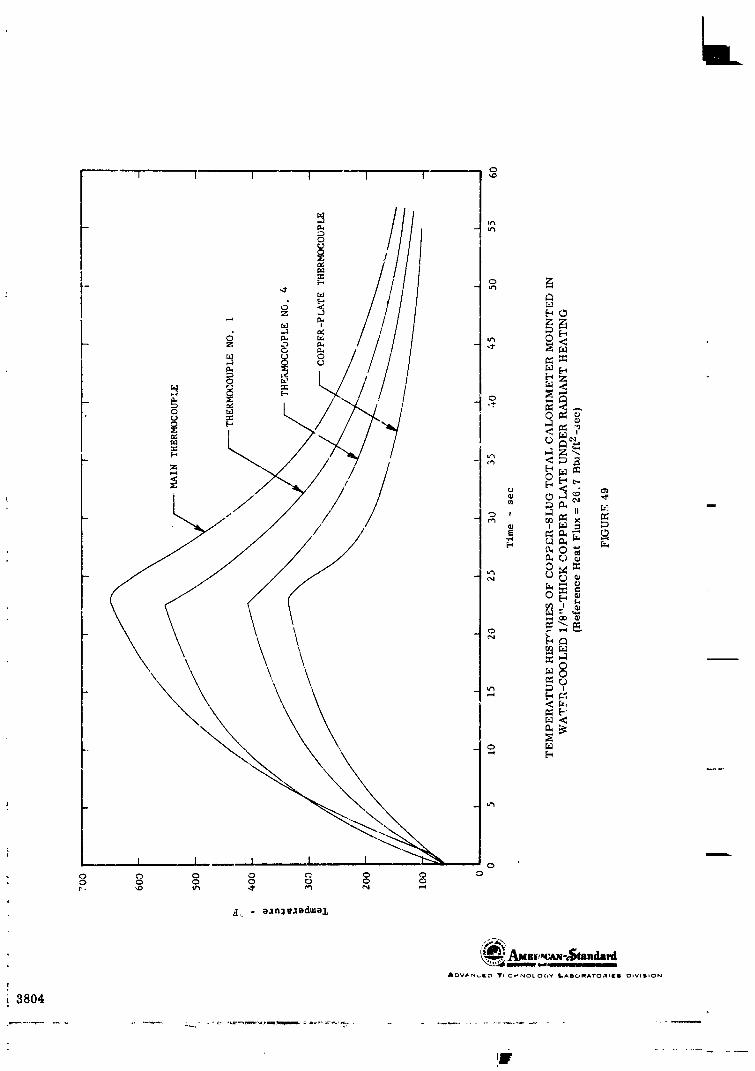
0I I I I I t '_


l l r l , o.,*4
J
ADVAN¢|O TEC.]-I_lOl.OOy i-_llOflATO_ll|| Os%'lllllON
;807
" r !
1965013399-117
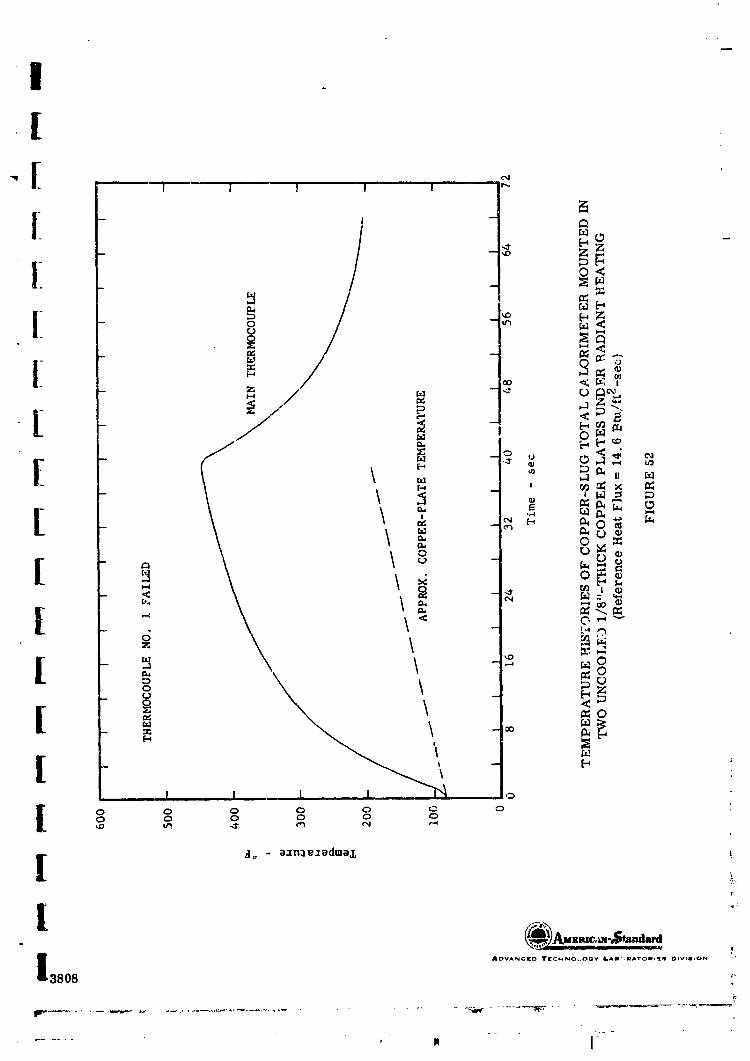
I[[ N"_ / I I I ! "
[ -- a _[_40 -_ -g z z_N
-- _
o --_ _,_I.- _ -- 1_, •
[ -- Z --.._
/ , ! "°"[ _-- _ [--I
[ - _.] II [z.]
' _x I__ - _
_ . -_,_ _ _ '_0 r,) __
: r,-) i cor_ - _ t)
_ ,_ -_ _: ®
- t-, ,0
Z
[ _ _
,_ -- _ ._
0 (3 0 0 0 L_ 0
_o - e_n:le_edme,i , !
! ,.
.%- k...'_../, , _ ., ....
3808 _
_r
........ _ N J-
1965013399-118

_OV_,_{(O _(_HNOLO_y _I IO_A -OMI( I OiVlt,.1N
3808
"- I I " -I" "'_-
1965013399-119

III[ -,
" '; I 1 I t
I" _ -_ "- .. __N
[ - + ]/+: ]_ <
L i.//.i1[ ° _- g
1 °++°_0
I - "+,+co +3 II
__ , +_Izl x m
! +'_++°- Ix<00
.__ oI,,,
--,30 f,_l 8
_0
I I I I o _
0 I_ 0 0 0 0 0
0 0 0 0 0 _
I A_VAIMCEp. I 'TEI_ 4I+OL<'_<_ LAIIII_IIIATI_III_II _IVISlON i I3809
I
- . . . -- .._, J
1965013399-120

"<Z"2_l I • _
ADVANCI_ YKCMN_.tLO_M l.,AmOm_TO_tl_. DIVI_mlO_
3810
-- _._ ....i
] 9650] 3399-]2]


o 5 5
rJ 0 _-'
\ \\ _-_ _-o _o _
--4
,_
,!2
S
e
0 0 0 ¢0 0 0 ,
ADVANCED Irl_C_NOLO_,e It._mORA'ro_l_a Dt'¢l_tlON
3812
1965013399-123

I([[[ -
Z
[ _Z
[ _ _, _
,,.e _
Z
_ o
2 <
_ .
[ _',_ :e_
[ 8 ';
\ ',
i. o ___,,t. ,I 1 _4 _t
I
_,_ie- ._.;/n':lt.[ - xnI1 :ls'el.l *:)ue.lo:To_i
3814 _"
' I
1965013399-124


1
r

- 3817
] 9650] _99-]27

&OVANCED TI_.C:_NOLOOV L_mO_A'VO_I[_ OIWlION
3819
1965013399-128

1965013399-129


&OV_NCK_ 'IrKCHNOLOOY _._lOIq_TO_l_¢l OIV,_ION
' 38g,_
ii ii ,11 ijiiii iii ii ii.
1965013399-131
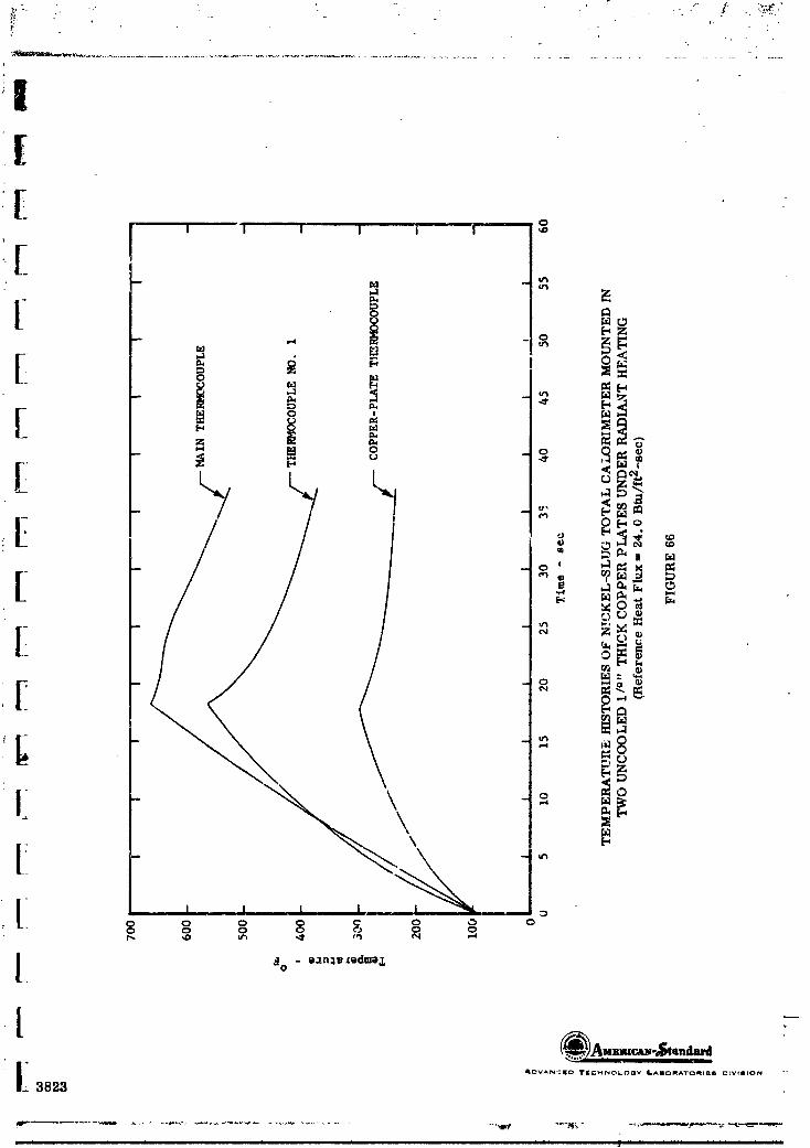
_.1 ii i i i i ii i i Ilml _ iiiii1.,,, ,., ,. ,,, ,,,, .,,,
1965013399-132

AI:_VANCEI_ 'I'iCHNO_.O_I Y lllAiiO;_lATO_lll_ll D_VIIION
_3219l
, ,,, , ............. ,, ,,,,, ,, ,, ,,,,,,,,,,,, .........................
1965013399-133


'_A_ ._na_," ' "" II II II
3161
"19650"13399-'135

I(• C
I I I I I I | ',O
[ _ -,,. _o
[ _
o _a
[ o'4
o ' _ Sl M
[ °
_a
[[
C 0 ¢'0 0 0 0 0
3162
m m m m mmm m m m" mm Ira,-n"
lg6501gggg-lg6
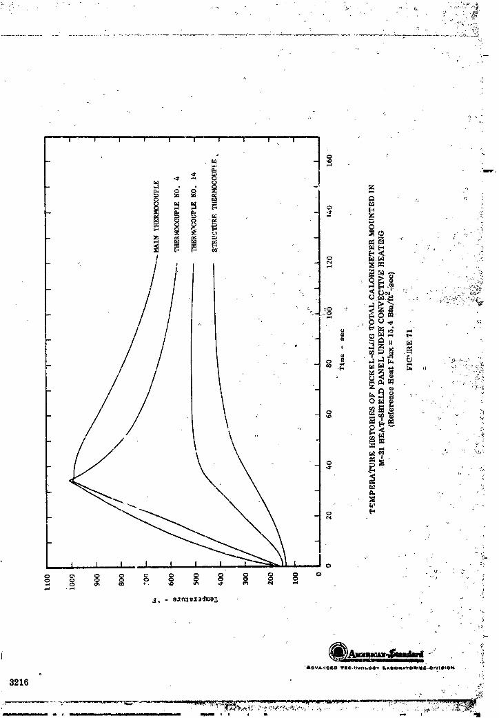
T
'_' " I " ' I I I I_ 'I I I I C I ' I
I• 0 _"
1-4 ""
- _ 1- -e I=4 .:>
____ . .
o. _ '',.
e _:q
. I_ i!
,. :. .,_0
e,4 - ,=_ 1
%,
o _
3216 ,, ,,:
1965013399-137

i ii i i t; • i "
1965013399-138

I
AC;VANC_ lriC_O_.OC_V Ii.,,,.llom,_-r_,-_,<ll i'llv i.,- ._
322 ";
-'11
1965013399-139

[
I I i I 'I I
0..12 '
\
- \ _\ES\ _
\ N_ mZ
\ \ Z0
F
_ _ _ _ _.,_'_,[-_ o
{-, {-, _ f..; r,J c.} f,.) -- ,-,
zI I I I I I o
I I I I ! I o0 C3 _ 0 0 0 0 0
:_a_* _I/n:l_ - xnl3 3eax a:)ua_,a_la_l
&OV_NCEO T[C_NO¢.O0_ i.,a_OmATO,,,l_O o_ _OIO_4
_825
1965013399-140
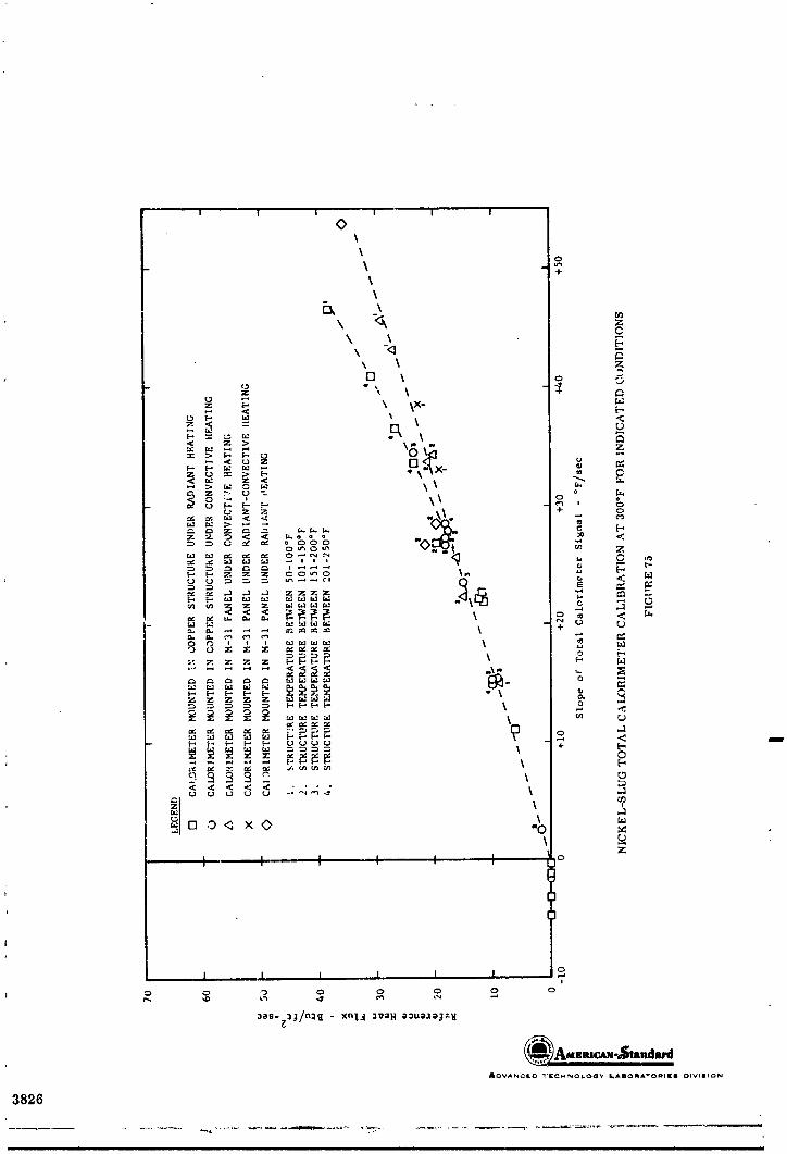
1 I I I I I oi
_OV_NC_ _'_CHNOLO_ _&_OR&TO_I_i _IVI_ION
3826
1965013399-141

I
I
I ' .""--" i I I IOx
\
[ ' _4-
\
Ii ' °\ -<_i[- ' o
z C] _ + C_
_ _ \ _x- <_ ,, z > ,,\ C
Z 0 ''_ > " 0
_ > o\_x-
o o ,,', 3 F,
[.,.]
[ __ _-_._-_ - ,_.
z
[]
[ _[l
-- i _ I. I I _ _ o
:._a_,-g:l._/n,.l_ - xnI,..[ :_e"}l aoua,ze._'-,_
I A_V_N_I_ 'IrE.:;,-¢NOLOCSy ._I)O_,,_A-O_II[,_ O.,'_IIION3_27
1965013399-142

, r ,' "_ , , _-
<>_\ +
\\\ m
z
5,, _o Zz \ _ o 0
" "' 5 \×-
= ,., _ _ _ O\x x- R °, ,.
=. m. = =_ -\ -_
= "_ SO i
- _ _: ___ \ + _<
_.; %,
;I +_ ntnO_3 xO \ _
o kI ' I ' ; I I ' I \ o z\,
i
o = o o o o :. o[
I.. _es- ::lJ/n::l_l - xnl,_1 :II'aH e",ue.ze_e_
,%,
yj- 3828
i i i lU i i i i i i iiii i i iiirli
1965013399-143
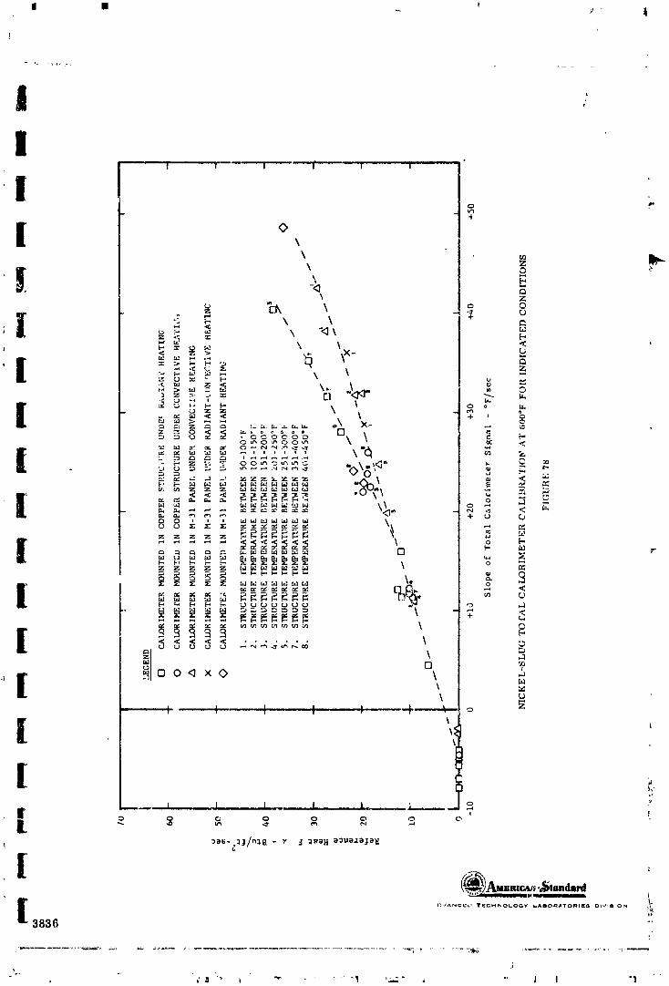
II [] m
)
I| I I |* I ! | "
I t '[ *,
_ z
_, \ o o
i z --,-_ u
p i-,
[-,
c,: , ,=_ .-*_[_=z'Z _- '-# :Z: q..l
o,,, o _ o o,,, \ \ '=
i ,, _ _ _ °7_, 77"7"7 .," "" vO -' '-'
,, _:._ o o :4_ - _ < -_
z z z z z [-.
z z b- z z , ,- \ _:
< < < < < ....... \
o '_
O0<)xO \ ._L_
\ ui I I I I "4"-- o
[ J| ' ,o o N o o o o o
[ ..........,............................ ;3836 ""
_ _I "" i "" " _1 ',-1" _ "" _ I "I
1965013399-144
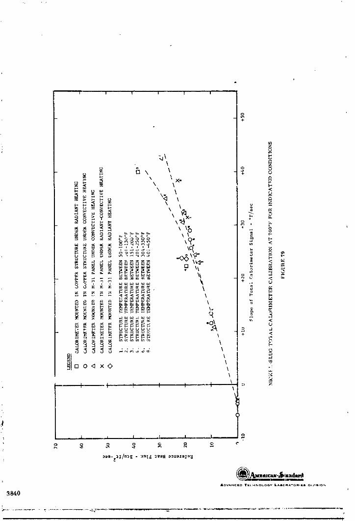
t
I I ! I I I
o+
I i i 1 I _ , I, ,£,o
r..
3840
1965013399-145

; j
• _i i i i i i iii 11 i i ,
1965013399-146

,i
! I ; 1 I I
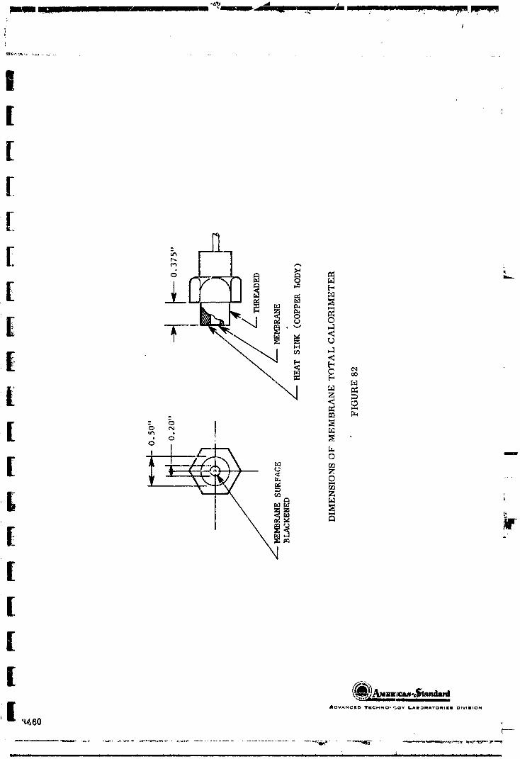
. ._,, , +r!,_ ' ............... .,.s ...... +_ ...... ,": ...... ;,,,,+-+Plp_++
[[[[[
E _r_
- o Nm
d d _
t °c Z_,,'I _ o
z _
_ Wf =_ -
[[[
i ADV,*_NGED TII:CMNO* _QY LAIONATOI_III{II DIVlIIION
T
' iIlJlil IIII IIIII I I I I I I I I II I.I i II I II If II ] Ilrlll IIIIIIi11 _ ]
1965013399-148

i o I I I
_I_V_N,_I[L, _l[Gi'_NO_OClPf LABI._iNA'TOIIli_f j IIIlVIIIION
32?5
1965013399-149

i I In i mug ..... _ .... _ _ i n m J m _ .kipun_ i,
L
!
IF__
3500 - ----
,_ q = 12 BTU/FT2-SEC (TcoRR = 3467°F)
30_0
_ q = 10 BTU/F'F 2-SEC ,TcoRR_ = 3095°F)
2500
q = 7 BTU/FT2-SEC (TcoRR = 2517°F)
• 2000 q = 3 BTU/FT--SEC (TcoRR = 2111_F)
q = II.2 BTU/'FT2-SECGI
_ .
| .,__._q = 8.3 fl,TU/!.-T2-SEC
i000 - _/-'"
_,.50_. I I Io I I
0 i0 2'.; 30 40 50 60 '
Time - sec
!
M-31 HEAT-SHIELD-PANEL SURFACE-TEMPERATURE AND
FR EE- STREAM GAS-TEMPEEATU._ E MEASUREMFNTS UNDER CONVECTIVE HFt- TING
31.,3INCHES DOWNSTREAM FROM POINT OF BOUNDARY-LAYer. INCEPT._O]',
FIGURE 84
A_VANC_ D Irq[CF, NC.L.OOy _A_lO_A"rOI11Orll OIVIIION
" 3843
1965013399-150
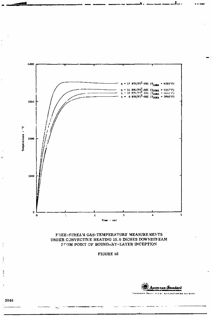
4000 ! , ! | !
.../_ q " 17 _TU]F'T2-SF.C(TcoI_ " 4255"F)
I
30_
I
i /,2000 ,i
1o_
iLj
o! I i I - I0 ", 2 3 4
Time -se¢
F'._EE-_CREA'd GAS-TEMPERATUR]_ MEASLrRE._4EI_TS
UNDER C_)NVECTI3;E HEATING 15.0 INCHES DOWNSTB EAM
_rOM POINT OF BOUND._I_Y-LAYER INCEPT?ON
FIGURE 85
3846
i i . i |
1965013399-151
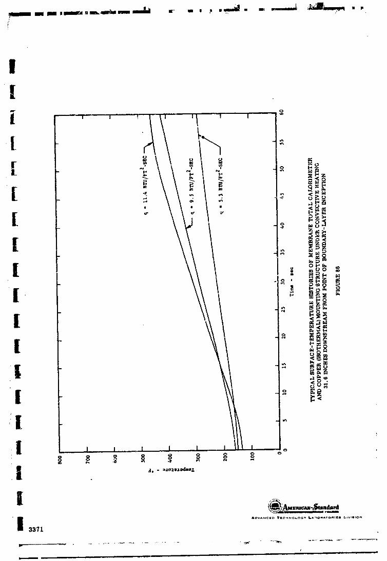

I I I I' I ) I I I t I " 1 I l
_ ,I _ __
{,.., 7-.<
•" :.,-:.. ., = :_:, f..-,>
- .-' .-- <,., ,? ,_ -_ z
,..i -Ul
' _-" --_ . [.., _ b,Z
-- '_ / _ ,_ O[ _--;J: _'O
m I ::-" _ _ I _ J
''_,,, Ii _.-:
- _ k ~o-" \
o \
I 1 . I I [---..J I I I I I I I I .._
_I_'VANCI_O _IGNNO_OOY _AIONATOHI|| GIVIII.,'N
3_45
ii i j _ ii . , -- L 7
"19650"13399-'153
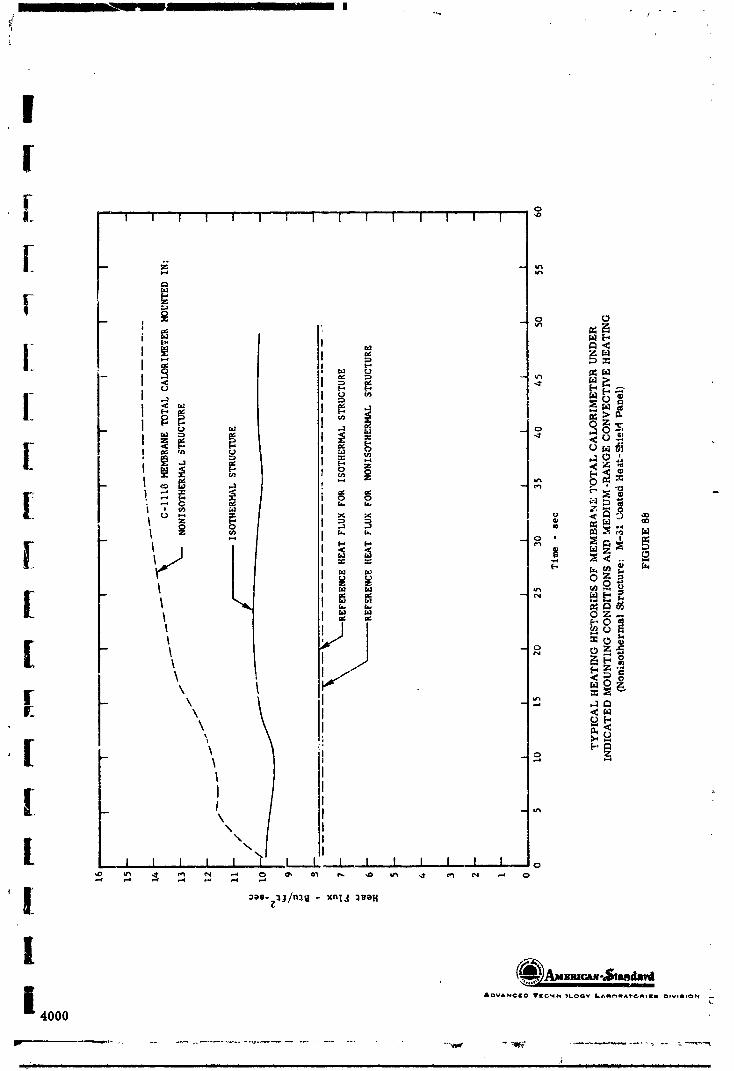
- Im- " II I a
1
II
' I I I | I I t I "1 I I I I I I
[ t "z _ _ o
I < _
[ _I _ ._ _
o _._m Z
0 0
_ _z__, -
\ <_
I
l ,_ I _
' _[\
| "--I I I I I I i, I I, I,, I I t I o
i ADVANClO T1¢C',4_ "_LOGY L^_l_,*,'S'C, nllCil O_VlIION --L
4000
1965013399-154

_(PIovANGED I"|CHNOL,".)_IV LAliO_ATO_I[I _nvlsloN
,' 4001
/
1965013399-155
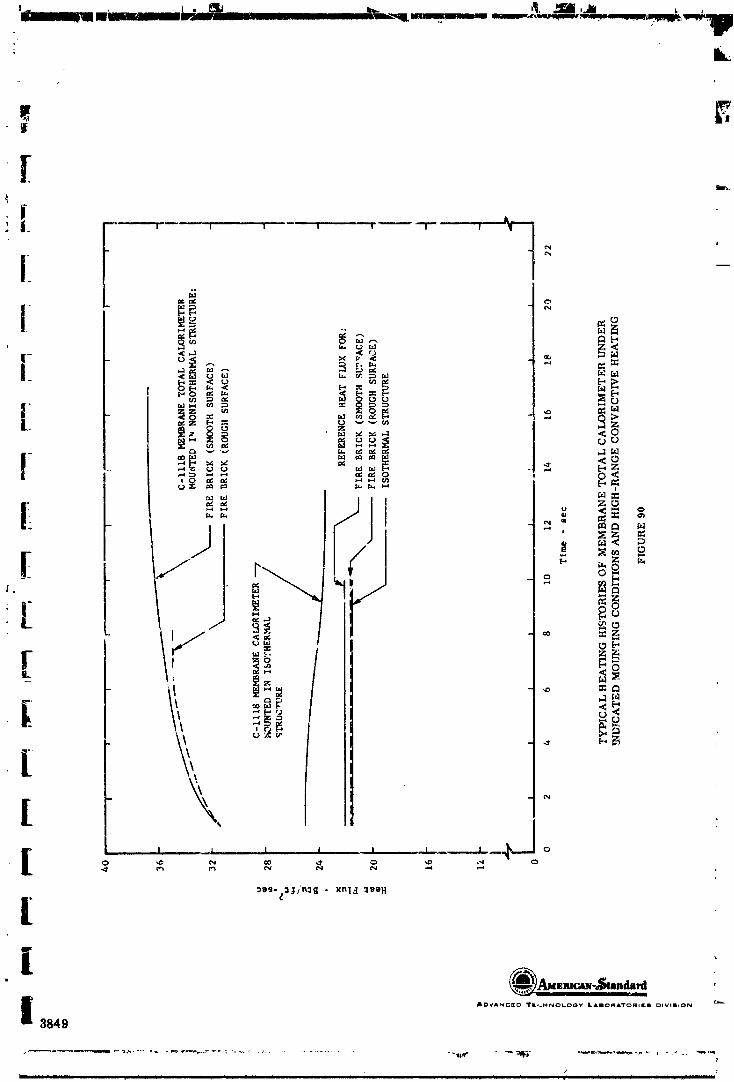
IF"
, Ik-
e g
I,
Ji [i
• =
_r,.2
f-
_ / _°-,., 0["
"o go
- ' .E_ ,o _:_
) -[ ,r , -, ,, , , , _------_--,1'---°L
[
3849
___ _ , I _ I I I . I I I II I I . I I . - IL I I _I I I I I II I [ [: - r
] 96503 3399-3 56
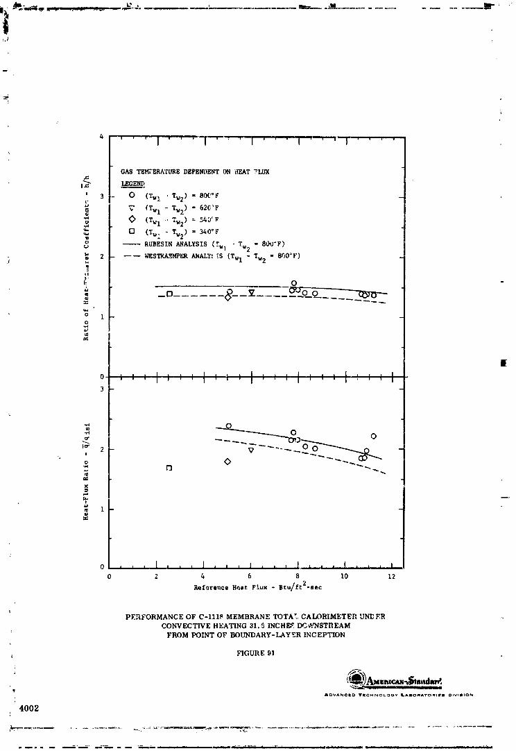
GAS TE_'ERATURE DEPENDENT ON HEAT FLUX
,:'_ LEGEND
' 3 0 (Twl ' Tw2) ffi 800°F
'_' 620 _F= _" _Twl - Tw2) =
<> (TwI -.Tw2)= S4O_F_ N (T_, " Tw2) = 340°F
o --- RUBESIN ANALYSIS '_ - Tw2 = 800_F)4,-Wl
2 ---- WESTKA_HPER ANAL¥,' _.S (Twl - Tw2 = 800°F)
o" _o v _-o 8e 8--............
ot_n:
I1
3
0 I I I I I , I I | I I I , , , J.., , , I , , , I
0 2 4 6 8 I0 12
Reference Heat Flux - Btu/ft2-sec
PERFORMANCE OF C-1118 MEMBRANE TOTAl. CAI.L)RIMETER UNE ER
CONVECTIVE HEATING 31.5 INCH_ e.I_VNSTREAM
FROM POINT OF BOUNDARY-LAYER INC EPTION
FIGURE 91
• t_)_..,_ .s,.,_ADVANCED TIZCHNOLOr._VLAIOR,_'I'O_II_I OIV'II,ON
'4002
1965013399-157

I
,[
_ ( 4 '" ,' _ , , I"" .... I .... I .... I ....
CA_ TENPERATURE= 400G°F
_- _ LEGEND:'_. [O
' 3 O EXPERIMENT_L DATA
_ -- RUBESINANALLSI$---- NEgTYAE_4PER ANALYSIS
[ •[ -V o¢,J
o oo o _.__. D_
_J
[ .0 • , : I : ! ,, , I ,. ,, : : I , , I ....' ' ' I ' I i ' ' : ' I .... t
[ _-
--....Io"
, 2 O0-'----0' O0
_ 0 0
® 1
1 0 .__._,__ ' i I , , i. , ) ,..,,,.,..,,,._,.,,,..,_j.... i ,,., ._.,__,_:_ 0 5 I0 15 20 25
Referem:eBeat FI,_x - Btu/f_2-se:_,-
F_RFORMANCE OF C-I118MEMBRANE TOTAL CALORIMETER UNDER
CONVECTIVE I{EATING 15.0INCHES DOWNZTREAMt ROM POINT OF BOUNDARY-LAYER INCEPTION
i
[ FIGURE 92
: i &C,.'ANC_I_ TWC'MNOtOOV LAIO_ATO_elE_ D_VIn_ON
l,4003
1965013399-158

,_AS TEM_',_RATURE = 5000°F
I'_ LEGERD
-_ ' 3 O EXPERI_NTAL DATA
Z-- RUB_SIN A_ALYSIS
--- WESTKAEMPER ANALYSIS
t_
u
_ 2_ ,N
,Uq• (3 0
,,_ "_ -----0 6) 00---------_ o"
q
3-
o"
2i
o o_m
= __O_ ___ Oo__ •
0 .... 1 .... i .... I , , , , I ....0 S J.0 15 20 25
Referen_._ Rea¢ Flux = Btu/ft2-sec
PERFORMANCF. OF C-1118 MEMBRANE TOTAL CALORIMETER UNDER
CONVECTIVE HEATING 6.0 INCHES DOWNSTREAM
FROM POINT OF BOUNDARY-LAYER INCEPTION
FIGURE 93
J _A-mt*.-/_..ImlAOVANGI_ TI[GHNOLOQy ILAIIK_*_A'TOPIII¢III [_IVI_tO_j
4004
n rill i i i n i i I i n i , , , ,.,,, ,,,,±_,w-_em,, .- i ii ii l lm.,i_ ,, ,, .%_, ,,mmmmm m
1965013399-159

IIIII
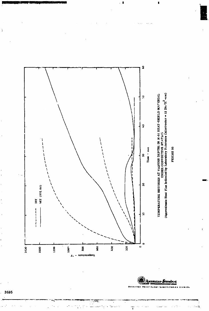
i,
o _ _"
f_
I I
, _ _
° _\\ °%%
%.%
%'".-.,.. I
.... I I ,_,i i ,, I .... i o
.4.- o.ln:l_,lodut_,L
AOVAI_I_.[D TI[,_,_ r OI..¢POy I*AeC_lq,_Tolql• • IPlVIIIION
3695
1965013399-161

I
[
_g
I \ _.°
_°
! m _
It.
I ' ' \ i, \ , o
• am" \ _
II
I i i , _ x I i , i _I.-.oo o -_ o o _ _ _ oi
| .__,o •
_896
1965013399-162
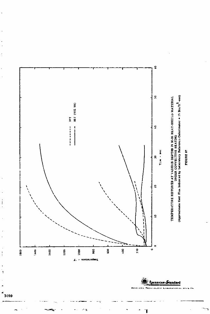
o
• .... 'I ! " I I I I I i _
i!
,,uag
I _I "_ o
, \ _._- -_\ _. _
\, \: o
\1
"'-..__ "'-. il o __
° o o _ °_, - aan=w._=dw,l.
I
3699
1965013399-163
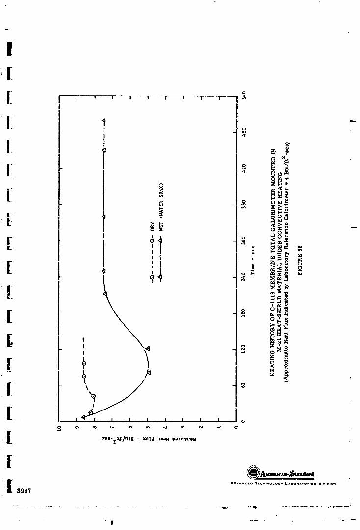
I
I
[ ",', , , , , , , ,
iI °_-Izl ""
I , I_l_ .o
[ _ _-' __._
o 6--._
I _ _ I_
[ '__, o°!
[ l_'_l I l l I I l l c,
oas-Z_J/n_g - xnI4 _ell p_r_s_:_A
_'."_."l _ -4_=II_,I :-
3997
lg_6013399-1_4

, , , , , , , , , _
AL'V_CI[O _rn_=u_P_Ol.oov I.Anlm,._p_,'rOaqI[_J Olvollom_
3996
Ii ,
1965013399-165

II[ _°" ' I I ! | _ I ! | I o_

3994
1965013399-167

ii| ,,,--°.:0! I I I ! I
I 0
' I ° Z['_
o _
' ° 'i?o o o _ "
, •
o_,§
i'o 0
, _ _,..,,..,.
I o04
N /.---.-I-._,I I I _ I I__ i l L4 o
_ _. _, _ o _, _ _. o
i
I ,_3995
' I
1965013399-168
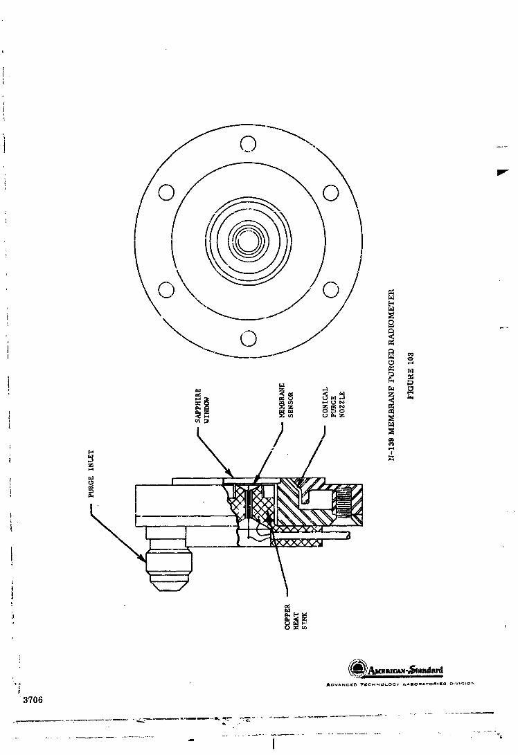
1965013399-169

!
Ii!!
.!
\ z_ _ =
i ° ++ +_"_!_O cJ _ _ o
Z
_ =
I , _ : , _ _ _ \o
i oa"-Z:Illn:I_ - ',n13 :lweX a:,ui,._o_a_l
I __=_3844
! _ "._ I,
1965013399-170

ADVAN¢_£O 'r[c),tNOLO0 Y LAilOl_ATO_ll;[| Ol_,lli,ON
8282
""P" I -" " " " -
1965013399-171

I
c'_
m
_ I" °
N
I I . - '
I ,,i 1 I I ,,, I t _ o0
^_ - l_Ugl_ _a1_UlOlp_
mc_i_- andard
1 37O7
1965013399-172
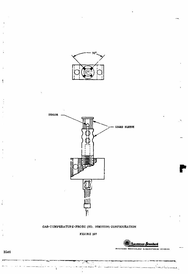
SENSOR
-_ GUARDSLEEVE
! I, I
GAS-TEMPERATUPE-PROBE (NO. 50M10100) CONFIGURATION
F_GURE 107
Ar3V&NCED _KCHNO_Q_Y LAmOM&TOMII[II_ ¢_IVImION
3586
, , . 1965013399-173
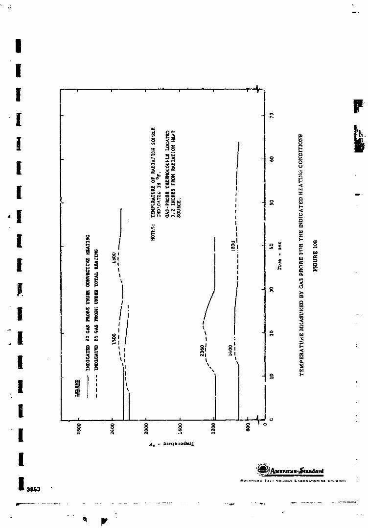
IIII " ' • ' ' ' ' "-n
I
I =
"! i _ __
i '| _ _
!l , / aI "i.. /} , _m m _ _-
I ] I N
/| _', , o
! -,-' " I l D.
! | 'II
' I| ' I I i ! _IJ 0 ,
";_..."'l- ,,
3_3
- o
] 9650] 3399-] 74
APPENDIX
IABULATED DATA ._D HESULTS
i
1965013399-175

1965013399-176

1965013399-177