N Specification for a Surface-Search Radar-Detection … INPUTS, OUTPUTS, AND LIMITS 2.1 INPUTS A...
70
_Technical Document 1930 September 1990 N Specification for a ,N Surface-Search Radar-Detection-Range Model Claude P. Hattan AE Approved for public release; distribution Is unlimited.
Transcript of N Specification for a Surface-Search Radar-Detection … INPUTS, OUTPUTS, AND LIMITS 2.1 INPUTS A...

_Technical Document 1930September 1990
N Specification for a,N Surface-Search
Radar-Detection-RangeModel
Claude P. Hattan
AE
Approved for public release; distribution Is unlimited.

NAVAL OCEAN SYSTEMS CENTERSan Diego, California 92152-5000
J. D. FONTANA, CAPT, USN R. M. HILLYERCommander Technical Director
ADMINISTRATIVE INFORMATION
The work described in this document was performed from January 1990 to June 1990 bythe Tropospheric Branch, Code 543, Naval Ocean Systems Center (NOSC), for the NavalOceanographic Office, Stennis Space Center, Bay St. Louis, MS.
Released by Under authority ofH. V. Hitney, Head J. H. Richter, HeadTropospheric Branch Ocean and Atmospheric
Sciences Division

CONTENTS
1.0 INTRODUCTION .................................................... 1
2.0 INPUTS, OUTPUTS, AND LIMITS ..................................... 2
2 .1 Inputs ......................................................... 2
2.2 O utputs ........................................................ 3
2.3 L im its ......................................................... 3
3.0 SURFACE-SEARCH RADAR-DETECTION-RANGE MODEL ............... 4
3.1 Radar Cross Section of Ship Targets as a Function of Aspect ............ 4
3.2 Radar Cross Section of Ship Targets as a Function of Height ............ 5
3.3 Calculations of Detection Range Using the Radar Cross-Section Models .... 8
3.4 Surface-Search Detection-Range-Model FORTRAN Program ............. 9
4.0 T EST CA SES ....................................................... 12
5.0 REFERENCES ...................................................... 15
APPENDIX: SURFACE-SEARCH RADAR-DETECTION-RANGE-MODELPROGRAM LISTING .................................................... A-1
FIGURES
1. Typical ship RCS variation with aspect .................................... 4
2. Ship radar cross section as a function of height ............................. 6
3. One-way propagation loss for a C-band radar for a cruiser-size target ........... 11
TABLES
1. Required surface-search radar system inputs ................................ 2
2. Required environmental inputs . ......................................... 2
3. Ship target RCS weighting factors ........................................ 7
4. Radar system test set input data ......................................... 12
5. Environmental test set input data ........................................ 12
6. Output data for Sys 1 and environment 1 .................................. 13
7. Output data for Sys 1 and environment 2 .................................. 13
8. Output data for Sys 1 and environment 3 .................................. 13
9. Output data for Sys 2 and environmc.,: 1 .................................. 13
iii

10. output data for Sys 2 and environment 2 .................................. 14
11. Output data for Sys 2 and environment 3 .................................. 14
iv

1.0 INTRODUCTION
A surface-search radar-detection-range model has been developed at the Naval Ocean SystemsCenter (NOSC). The model can be used to assess the effect of the environment on the performanceof surface-search radar systems. Additionally, the effects of radar cross section (RCS) variability as afunction of viewing angle, ship displacement, height of the ship, and range are also modeled. Twosimplified ship target RCS models are combined to calculate the RCS variability. One of the simplifiedmodels provides RCS as a function of viewing angle, while the other gives the distribution of RCS as afunction of height of the target vessel. Five classes of ship targets are modeled, ranging from small(patrol boats) to very large warships (aircraft carriers). Detection ranges for other ship classes can beinferred from their size relative to the ship targets that are used in the model. Environmental effectsare accounted for by incorporating the U.S. Navy Oceanographic and Atmospheric Library (OAML)Standard Electromagnetic (EM) Propagation Model (Hattan, 1990) into the model. The softwareimplementation of the model is written in ANSI Fortran 77, with MIL-STD-1753 extensions. The pro-gram provides the user with a table of expected detection ranges for the various target ship classeswhen the program is supplied with the propei radar system and environmental inputs.
6
Acoesslon For
DTC TAB El -..tUnannounced [3just ifcation
By-,-
Distribution/
AvailabilitY 0,46
Avail and/OrD Is Special

2.0 INPUTS, OUTPUTS, AND LIMITS
2.1 INPUTS
A number of radar system and environmental inputs are required to determine the detectionrange of a surface-search radar system. The necessary radar system paramcters are given in Table 1.The required environmental inputs are provided in Table 2. The antenna beamwidth and elevationangle parameters of Table I are not required for an omnidirectional antenna type. The input param-
eters of Table I and 2 are identical to the required inputs of the OAML Standard EM Propagation
Model, with three exceptions. The receiver/target height entry of the Standard EM Model is not used
and two new inputs are required: the free-space detection range of the radar for a I m2 target and
the maximum instrumented (unambiguous) range of the radar. The radar free-space range can be Lnl-
culated by using the OAML Radar Free-space Detection Range Model (Hattan, 1989) and the unam-
biguous range obtained from either the radar system manual or calculated by using the methoddescribed by Patterson (1988). Shorthand variable names are given for inputs that are used in equa-tions or other tables in subsequent sections of the text.
Table 1. Required surface-search radar system inputs.
Parameter Units Valid Input Range
Frequency, f MHz 100.0 to 20,000.0Height of Transmitting Antenna, Ht m 1.0 to 100.0Transmitting Antenna Polarization n/a Horizontal, vertical, or circular
Transmitting Antenna Type n/a Omnidirectional, sin(x)/x,cosecant-squared, height-finder,or specific-system height-finder
Antenna Beamwidth, BW deg >0 to 45.0Antenna Elevation Angle,,zo deg -10.0 to 10.0Maximum Instrumented Range, Ri nmi 10 to 200.0Radar Free-Space Range for
1 m2 Target, R1 nmi 1 to 1000.0
Table 2. Required environmental inputs.
Parameter Units Valid Input Range
Evaporation Duct Height, 8 m 0.0 to 40.0Surface Wind Speed, W, kt 0.0 to 50.0Height Array, Hi - 2 to 30
Elements m 0.0 to 10,000.0M-unit Array, Mi- Each
Element Corresponding tothe Like-Number HeightArray Element M 0.0 to 2000.0
2

2.2 OUTPUIS
The only output is a table of predicted detection ranges for five ship target classes for the speci-fied inputs of Tables 1 and 2. The target ship classes are (1) aircraft carrier, (2) cruiser, (3) de-
stroyer, (4) frigate, and (5) patrol boat. Sample program outputs for a variety of environmental andradar system inputs are presented in section 4.0.
2.3 LIMITS
The surface-search detection-range model described in this document will return a range value innautical miles, limited to 200 nmi, for radar system operational parameters within the range of validityof the inputs of Table 1 and for environmental inputs within the range of validity of Table 2.
3

3.0 SURFACE-SEARCH RADAR-DETECTION-RANGE MODEL
The detection of large, complex targets by a radar is difficult to model accurately. Small targets,
such as small aircraft or missiles, in the far field of a radar system are usually assumed to interceptand scatter a plane wave, which is equivalent to saying that they behave as point source targets. Thisis generally not the case for ship targets. Ships are large and complex enough to scatter radiation thatis not a plane wave, especially within the radar horizon. Large fluctuations in received signal strengthas a function of range, aspect angle, target size, radar antenna height, and the propagation environ-ment can occur, and these signal excursions are equivalent to variations in the RCS of the target ves-sel. Any analysis of the variations of ship target RCS generally requires that a simplified model of tar-get shape be used. The following subsections describe two RCS models which can be combined topredict detection ranges for various classes of ship targets. One model describes the variation of RCS
as a function of aspect angle. This model can be used to determine the minimum, average, and maxi-mum detection range of a ship target by establishing the radar receiver detection threshold corre-sponding to each of these RCS values. A second model, which gives the height variation of RCS,allows the propagation loss for any range to be determined.
3.1 RADAR CROSS SECTION OF SHIP TARGETS AS A FUNCTION OF ASPECT
The RCS of a ship is quite dependent on the azimuthal angle of incidence (aspect). Figure I is an
example of a fairly typical variation of RCS with aspect as measured by Queen and Maine (1971).The polar diagram of Fig. 1 :.as three lines plotted which represent the 20, 50, and 80 percentile val-ues of the RCS distribution function, inner-to-outermost curves, respectively. The RCS values are plot-ted in units of decibels above a 1 square-meter target (dBsm). There is an increase in RCS abeamand significant reductions in RCS at near-bow or near-stern angles of incidence, which should beexpected. The fluctuations of RCS with aspect, of 10 dB or greater, can cause significant variations indetection range.
(BO(000
3O* 3.3O*
2 OR 24(f
150°r 21(f
180
Figure 1. Typical ship RCS variation with aspect.
4

Skolnik (1974) has shown that the total radar cross section of a ship target can be related to the
displacement of the vessel and the radar frequency. This relationship is given by
a = 52 fl/ 2 D3/ 2 (1)
where f is the radar frequency in megahertz and D is the ship's displacement in kilotons. This equa-
tion was developed based on an empirical fit to values of the measured 50th percentiles of the RCS
distribution function (omitting the broadside peak) on data obtained by the Naval Research Laborato-ry's Target Characteristics Branch. Inspection of these data indicates approximately an 8-dB excursion
from this average value to the measured RCS minimums. Similarly, a 13-dB range from average to thebroadside peak characterizes the maximum RCS.
3.2 RADAR CROSS SECTION OF SHIP TARGET'S AS A FUNCTION OF HEIGHT
The RCS variation shown in Fig. 1 is not solely due to the variation in total area of the ship as a
function of aspect angle. There is also a considerable variation in RCS as a function of height. Thehull, superstructure, and mast/antenna areas all have different microwave reflective properties becauseof their shapes and sizes. The fact that the various radar reflectors are not concentrated at a singlerange, or orientation, further complicates the nature of the reflected wave. The reflected energy as"seen" by the radar receiver is, of course, the sum of the signals returned from the various reflectingsurfaces illuminated by the radar.
The basic transmission equation for a monostatic radar, from Kerr (1951), is
Pr (G A)2 a F(
Pt (4;r) 3 R4 (2)
where
Pr is the power received
Pt is the power transmitted
G is the antenna gain
X is the wavelength
a is the RCS of the target
F is the pattern propagation factor which, is defined as the ratio of the actual electricfield at R to the free-space electric field at R
If there are n multiple targets at the same range, R, then the power received is the sum of the
reflected energies from the various targets. If we assume that the cross sections of these n multipletargets at R are defined by cr(h), where u(h) is the cross section of the target appropriate to height h,
and all of the o(h)'s are fully contained within the vertical and horizontal beamwidth of the radar,then Eq. 2 can be rewritten
(G A)2 1 r(h) -P- n (3)Pt (4;r)
3 R4
provided F(h) does not vary significantly across the surface of a(h). If F(h) does vary over the verti-
cal extent o, a(h), but cr(h) is uniformly distributed across the same vertical extent, then the averageF4, defined as T(h), can be used in Eq. 3 to replace F(h)4. If c(h) is replaced by or w(h), where
5

w(h) represents the fractional weighting factor for the cross section represented by each cr(h), then the
summation on the right side of Eq. 3 can be replaced by
X a(h) F(h)4 = a w(h) F(Qh' (4)
with the restriction that the summation over the w(h) = 1. This equation allows a ship target to be
treated as if it were an ensemble of individual targets (which it is) by summing the individual contribu-
tions to the total ship RCS over the vertical extent of the ship, assuming that the variation in RCS is
only a function of height.
50 I .. ................................................................................................. M A ST
45-
40..........................................................................SU PER
............ ".... ... SU-PER
35 -
30
25
0 20
1
.20
215
1 0 -. . . . . . . . . . . . . . . . . . . . . . . . .. . . . . . .. .. . . . . . . . . H L
5
00 5 10 15 20 25 30 35 40
RADAR CROSS SECTIUN PER UNIT HEIGHT IdBsm/m)
Figure 2. Ship radar cross section as a function of height.
Anderson (1986) has reported on a model developed at the NOSC by Hitney that gives the RCS
distribution with height above the waterline. An example produced by this model is given in Fig. 2 for
a cruiser-size target. RCS is expressed as decibels above a one square-meter target per meter of height
(dBsm/m). The labels at the right side of Fig. 2 indicate the area of the ship responsible for the RCS."Hull" is used to define the area from the waterline to the top of the main deck. "Super" is the
height region above the main deck, including all major radar antennas, that comprises the superstruc-
ture of the ship. "Mast" applies to those heights above the superstructure, which primarily consist of
mast and whip antenna structures. These boundaries are shown by the horizontal dashed lines. Note
that in this model the entire RCS of the ship is due to return from the superstructure. In reality there
is some return from both the hull and the mast areas, but it is primarily the superstructure, with its
many reflectors, that is the main contributor to the total RCS of the ship. Anderson (1986) has com-
pared ranges by using the above model and one that includes a small contribution from both mast andhull areas, and the ranges are nearly identical for a wide range of environments. The distribution ofRCS per unit height for other ship targets is assumed identical to that shown in Fig. 2.
6

Table 3. Ship target RCS weighting factors.
Ship Class
Height (m) CV CG DD FF PB
2.50 0.04673.50 0.21344.50 0.30835.50 0.0151 0.0212 0.26256.50 0.0151 0.0212 0.1045
7.50 0.0151 0.0151 0.0818 0.02458.50 0.0151 0.0634 0.0970 0.01519 50 0.0151 0.0688 0.1229 0.0151
10.50 0.0634 0.0688 0.1402 0.007411.50 0.0688 0.0933 0.1318 0.0025
12.50 0.0688 0.0995 0.119313.50 0.0933 0.0995 0.104914.50 0.0995 0.0891 0.047515.50 0.0995 0.0847 0.047516.50 0.0891 0,0847 0.0111
17.50 0.0180 0.0847 0.0541 0.011118.50 0.0180 0.0847 0.0337 0.007719.50 0.0436 0.0541 0,0337 0.006920.50 0.0821 0.0337 0.0208 0.006921.50 0.0821 0.0337 0.0079 0.0069
22.50 0.1113 0.0208 0.0079 0.005523.50 0.1186 0.0079 0.0067 0.003424.50 0.1151 0.0079 0.0049 0.002925.50 0.1010 0.0067 0.0049 0.001126.50 0.1010 0.0049 0.0049 0.0011
27.50 0.0645 0.0049 0.004928.50 0.0402 0.0049 0.004929.50 0.0402 0.0049 0.004430.50 0.0094 0.0049 0.002431.50 0.0094 0.0044 0.0024
32.50 0.0080 0.0024 0.002233.50 0.0058 0.0024 0.000834.50 0.0058 0.0022 0.000835.50 0.0058 0.0008 0.000836.50 0.0058 0.0008
37.50 0.0052 0.000838.50 0.002839.50 0.002840.50 0.001741.50 0.001042.50 0.0010
7

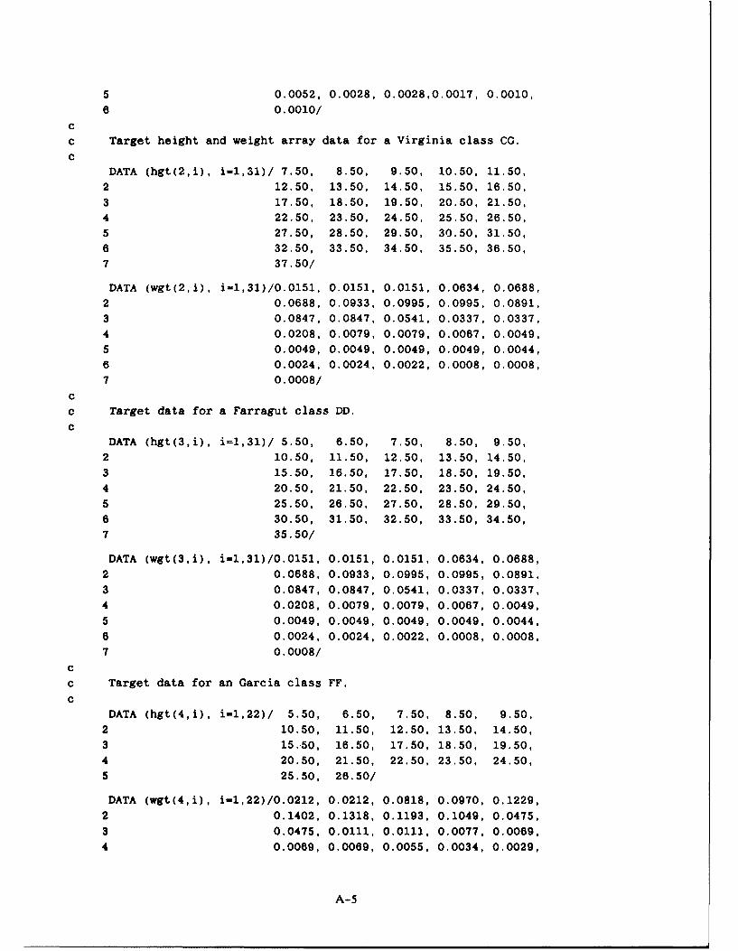
Using Hitney's RCS distributon model, it is possible to construct a table of weighting factors,w(h), for several different ship targets. Table 3 contains the weighting factors for five classes of shiptargets and the height at which the factors were evaluated. The ship classes represented are a patrol
boat, a frigate, a destroyer, a cruiser, and an aircraft carrier. A discrete height interval of 1 meter was
used to construct the table, and the weighting factors were evaluated at the midpoint of the interval.
Superstructure height measurements were obtained from Jane's Fighting Ships (1980) and represent aship that is approximately the class average for US Navy vessels. The patrol boat is the exception, butit is representative of the Soviet 210-ton Stenka- and Osa-class boats, which are in world-wide opera-tional use. The frigate measurements are taken from a 3400-ton Garcia-class ship, the destroyer'sfrom the 5000-ton Farragut class, the cruiser's from the 10,110-ton Virginia class and the aircraft car-rier's are from the 85,360-ton Kitty Hawk class.
3.3 CALCULATIONS OF DETECTION RANGE USING THE RADAR CROSS-SECTION MODELS
Using the distributed targets of Table 3, it is possible to use Eq. 1, 3, and 4 to calculate the totalreceived power, Pr, at any range, R, if F(h) is known. When Pr is equal to (or greater than) theradar receiver's signal-to-noise (detection) threshold, the target can be detected. The greatest rangewhere this occurs corresponds to the maximum detection range for the average RCS value obtainedfrom Eq. 1. F(h) can be obtained as a function of range by using the OAML Standard EM Propaga-tion Model. The Standard EM Propagation Model returns the pattern propagation factor, F, in deci-bels, for user-qpecified geometric, environmental and EM system inputs. F accounts for all of thepropagation effects on the radar system. Assuming that the average value of F(h) is constant over areasonably small height interval of the target vessel, Eq. 4 can be used to sum the contributions from
each individual height element by using the weighting factors obtained from Table 3. The averagevalue of F(h) is evaluated at the same height as the weighting factors of Table 3. By a proper selec-tion of the range, R, the actual detection range for any ship target can be determined in an iterativemanner.
The radar system detection threshoi'I is determined from the free-space detection range input ofTable 1. This input is based on the detection of a 1 square-meter target, but can be scaled to the
actual size target by using the following relationship (Kerr, 195 1):
Rfs = R a 1/4 (5)
where Rfs is the radar free space range for the desired target cross section, R1 is the radar free-spacerange for a 1 square-meter target, and or is the average target cross section from Eq. 1. Rfs can be
used to determine the equivalent one-way propagation loss that the radar can sustain and still detectthe target. The one-way propagation loss (detection threshold), in decibels, for the average RCS ofthe ship target is obtained by using the following equation "Kerr, 1951):
La 5g = 32.44 + 20log(f) + 20log(Rfs) (6)
where f is the radar frequency in megahertz and Rfs is in kilometers. The actual one-way propagationloss, L, at any range can be determined by using the following equation (Kerr, 1951):
L = 32.44 + 20log(f) + 20log(R) - 20iog(F) (7)
8

The greatest range where Lay5 = L is the actual detection range of the desired target. Substituting thesummation of Eq. 4 into Eq. 7 yields
L = 32.44 + 2Olog(J) + 2Olog(R) - 5o 1W~h) T- (8)
Equation 8 is the most useful form of the loss equation to determine the detection range (i.e., whereL = Layg).
Equation 8 can be used to determine the minimum and maximum detection ranges as a functionof aspect for ship targt.. also. Since the broadside maxi-num of the RCS distribution function isapproximately 13 dB greater than the average RCS, the maximum detection threshold is given by
Lm, = Layg + 13 (9)
Similarly, the minimum RCS of the ship is 8 dB (at near-bow or near-stern angles) less than the aver-age value, so that the detection threshold is
Lmin = Layg - 8 (10)
Since Lmax is greater than Layg, the corresponding detection range will also be greater, and it followsthat Lmin will yield a shorter detection range.
3.4 SURFACE-SEARCH DETECTION-RANGE-MODEL FORTRAN PROGRAM
The surface-search radar-detection-range model is implemented in a program called SSRDRT.SSRDRT is written in ANSI Fortran 77 with the allowable MIL-STD-1753 extensions. SSRDRT calcu-lates three detection ranges for each of the five ship targets of Table 3 for the specified EM systemand environmental parameters of Table I and Table 2. To use SSRDRT, the operator must compileand link the routines that constituie the program. A complete list of all subroutines is included in theappendix. The subroutines are listed in alphabetical order following lists of the MAIN and SSRDRTroutines, the TARGET block data, and the common block "include" files. No EM system or environ-mental libraries are supplied with SSRDRT, though a limited number of environmental and EM systemdata sets for test purposes are listed in section 4.0.
A demonstration program, MAIN, which acts as a driver for the SSRDRT program is included todemonstrate the use of the program. The driver simply calls SSRDRT to initiate the program. In addi-tion to MAIN, several subroutines allow the operator to enter environmental and EM system datafrom the keyboard or files. These subroutines, SYSFIL, ENVFIL, ENVINP, and SYSINP, are r't
intended as part of the SSRDRT program, but are only for use in verifying the correct operation ofthe SSRDRT program. Another routine, PRNRNG, is similarly included. PRNRNG prints a table ofthe range values, obtained from SSRDRT, for each of the five targets and the three detection thresh-olds for each target.
All but five of the subroutines that constitute SSRDRT are subroutines that are part of the OAMLStandard EM Propagation Model, FFACTR. The operation of these subroutines is documented else-where (Hattan, 1990) and will not be explained in any great depth here. Since SSRDRT uses a singleset of environmental and EM system inputs for determining the detection ranges of the five targets,FFACTR was modified by placing the ANTPAR, DCONST, GETK, MPROF, and OPCNST subroutinecalls in SSRDRT. This was suggested by the FFACTR documentation to avoid redundant subroutinecalls. The operational sequence of SSRDRT is detailed in the following paragraphs.
9

The MAIN program calls ENVINP and SYSINP to allow the operator to enter the environmentaland radar parameters of Table I and Table 2. Subroutine TARGET contains the block data for thefive ship targets' RCS weighting factors and heights of Table 3 and an array of the target ships' ton-nage to the 3/2 power. Once these parameters have been entered, SSRDRT is called. SSRDRT initial-izes the FFACTR program constants by calling, in order, the MPROF, GETK, ANTPAR, OPCNST.and DCONST subroutines. After the constants have been initialized, subroutine RTLOOP is called todetermine the detection ranges for each of the targets and thresholds. When the detection rangeshave been calculated, RTLOOP terminates and returns to SSRDRT, which then returns to MAIN.MAIN then calls PRNRNG to print the range values. The program is then terminated.
RTLOOP is the subroutine which implements Eq. 8 to build the surface-search radar-detection-range table. The subroutine is essentially composed of two nested DO loops. The outer loop is thecontrolling loop for the five targets and the inner loop calculates the detection range for the three de-tection thresholds, Lmin, Lavg, and Lmax, as a function of target aspect angle.
RTLOOP calculates the threshold values, Lmin, etc., for the individual ship targets. RTLOOP alsocalls subroutine RARRAY to build a three-element array for each target, which is used in a searchscheme to minimize the time necessary to determine the detection range. The first element is 370 km(200 nmi), the maximum range allowed; the second is the minimum range at which the diffractionfield calculations are valid, rd; and the third is the range to the end of the optical interference re-gion, ro. ro is determined by a call to the FFACTR subroutine OPLIMIT. rd and ro are computedby using the height closest to the median value of the target RCS obtained from Table 3 (15.5 metersfor the cruiser). This height is very nearly 1/3 of the superstructure height difference above the maindeck, as shown in Fig. 2. These ranges only approximate the overall behavior of the target, but areuseful in shortening the search time. The one-way propagation loss of Eq. 8 is obtained by referencingthe FLOOP subroutine for each of the three ranges from RARRAY. Subroutine FLOOP performs thesummation of Eq. 4 at any range, R, by iteratively calling the FFACTR subroutine for each targetheight of Table 3. The returned value of F, in decibels, from FFACTR is converted to a pure num-ber, raised to the fourth power, multiplied by the appropriate weighting factor and summed over theheight range of the superstructure.
The threshold loop of RTLOOP is used to determine the actual detection range for each of thethree thresholds, starting with Lmin. This is done by comparing the one-way propagation loss fromEq. 8 at a range, R, to the applicable threshold. R is decreased, in steps, from the maximum range of370 km (200 nmi) to rdj to ro, and from ro in 1-km steps. At each step, the propagation loss fromEq. 8 is compared to the threshold value. If the threshold at any range R is greater than, or equal to,the one-way loss, then the actual detection range is greater than, or equal to, R. Once the thresholdexceeds the one-way loss, the exact detection range is determined by iteratively halving the differencebetween the two range values that bound the threshold until the range difference between iterationsteps is less than 0.1 km. When this occurs, the last range used is declared the detection range forthat threshold, and this value is stored in an array to be printed when all five targets have been proc-essed. This procedure is then repeated for the other two thresholds and repeated again for the othership targets. A minimum range of 5.0 km (2.7 nmi) is the shortest range allowed as a valid detectionrange for any threshold or target. Additionally, all calculated detection ranges are limited to the maxi-mum instrumented range of the radar.
10
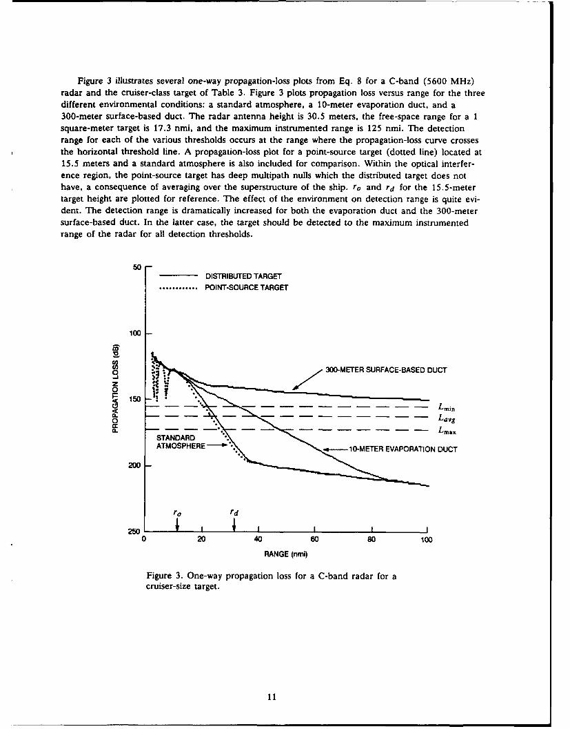
Figure 3 illustrates several one-way propagation-loss plots from Eq. 8 for a C-band (5600 MHz)radar and the cruiser-class target of Table 3. Figure 3 plots propagation loss versus range for the threedifferent environmental conditions: a standard atmosphere, a 10-meter evaporation duct, and a300-meter surface-based duct. The radar antenna height is 30.5 meters, the free-space range for a 1square-meter target is 17.3 nmi, and the maximum instrumented range is 125 nmi. The detectionrange for each of the various thresholds occurs at the range where the propagation-loss curve crossesthe horizontal threshold line. A propagation-loss plot for a point-source target (dotted line) located at15.5 meters and a standard atmosphere is also included for comparison. Within the optical interfer-ence region, the point-source target has deep multipath nulls which the distributed target does nothave, a consequence of averaging over the superstructure of the ship. ro and r d for the 15.5-metertarget height are plotted for reference. The effect of the environment on detection range is quite evi-dent. The detection range is dramatically increased for both the evaporation duct and the 300-metersurface-based duct. In the latter case, the target should be detected to the maximum instrumentedrange of the radar for all detection thresholds.
50-DISTRIBUTED TARGET
............ POINT-SOURCE TARGET
100 -
O 300-METER SURFACE-BASED DUCT
0 150
LminIo Lay5C" . . . . . . . -- ,-.. .LmaxSTANDARD ".
ATMOSPHERE'' ".---lG1O-METER EVAPORATION DUCT
200
ro rdI I I
0 20 40 60 80 100
RANGE (nmi)
Figure 3. One-way propagation loss for a C-band radar for acruiser-size target.
11

4.0 TEST CASES
A number of radar system and environmental inputs are required to determine detection rangesfor surface search radar systems. Table 4 lists radar system parameters for two test case systems, Sys 1and Sys 2, which are used to verify the proper operation of the SSRDRT program. Three differentenvironmental test case conditions, EnvI through Env3, are listed in Table 5. The variable names ofsections 2.0 and 3.0 are used in the tables. The environment of EnvI corresponds to a standardatmosphere M-unit profile, a 0-meter evaporation duct height, and 10 knots of wind. Env2 uses thesame M-unit profile as Envl, but the wind speed is 0 knots and a 10-meter evaporation duct is pre-sent. Env3 has an M-unit profile that contains a 100-meter surface-based duct, a 0-meter evaporationduct, and 5 knots of wind. Both of the radar system test cases use each of the environments.
Table 4. Radar system test set input data.
Parameter Sysi Sys2
f, MHz 5600.0 9525.0Ht, m 30.5 24.4R, nmi 17.3 12.3Ri, nmi 125.0 125.0Polarization Horizontal HorizontalAntenna Type Sin(x)/x Sin (x) /xBW, deg 12.0 18.0/'o, deg 0.0 0.0
Table 5. Environmental test set input data.
Parameter EnvI Env2 Env3
0.0 10.0 0.0t 0.0 0.0 5.0
H2,2 (M, M) (0.0, 339.0) (0.0, 339.0) (0.0, 350.0)H3,M3 (m, M) (1000.0, 457.0) (1000.0, 457.0) ( 270.0, 381.9)H5, M 5 (m, M) (10,000.0,1519.0) (10,000.0,1519.0) (300.0, 340.0)
(m, M) n/a n/a (1000.0, 422.6)(m, M) n/a n/a (10,000.0,1484.6)
Tables 6 through 11 list the expected output data for the different radar/environmental test cases.The outputs, in nautical miles, are listed to the nearest 0.1 nmi, and the SSRDRT program is consid-ered to be operating correctly if the output is within 0.1 nmi of the value listed in the appropriatetable.
12
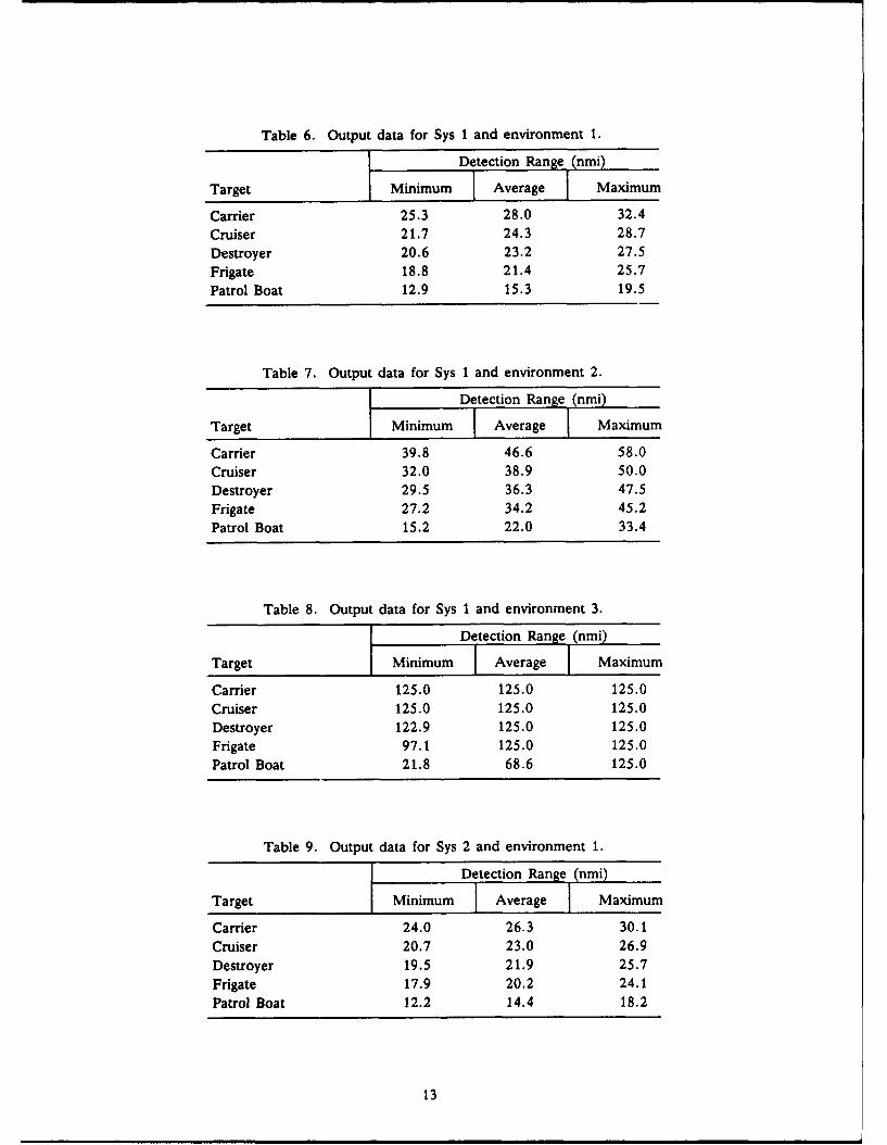
Table 6. Output data for Sys 1 and environment 1.
Detection Range (nmi)
Target Minimum I Average Maximum
Carrier 25.3 28.0 32.4Cruiser 21.7 24.3 28.7Destroyer 20.6 23.2 27.5Frigate 18.8 21.4 25.7Patrol Boat 12.9 15.3 19.5
Table 7. Output data for Sys 1 and environment 2.
Detection Range (nmi)
Target Minimum I Average Maximum
Carrier 39.8 46.6 58.0Cruiser 32.0 38.9 50.0Destroyer 29.5 36.3 47.5Frigate 27.2 34.2 45.2Patrol Boat 15.2 22.0 33.4
Table 8. Output data for Sys 1 and environment 3.
Detection Range (nmi)
Target Minimum I Average Maximum
Carrier 125.0 125.0 125.0Cruiser 125.0 125.0 125.0Destroyer 122.9 125.0 125.0Frigate 97.1 125.0 125.0Patrol Boat 21.8 68.6 125.0
Table 9. Output data for Sys 2 and environment 1.
Detection Range (nmi)
Target Minimum I Average Maximum
Carrier 24.0 26.3 30.1Cruiser 20.7 23.0 26.9Destroyer 19.5 21.9 25.7Frigate 17.9 20.2 24.1Patrol Boat 12.2 14.4 18.2
13

Table 10. Output data for Sys 2 and environment 2.
Detection Range (nmi)
Target Minimum Average Maximum
Carrier 60.1 72.7 93.6Cruiser 48.6 60.9 81.5Destroyer 44.8 57.0 77.5Frigate 42.4 54.6 75.0Patrol Boat 26.5 37.9 57.6
Table 11. Output data for Sys 2 and environment 3.
Detection Range (nmi)
Target Minimum Average Maximum
Carrier 125.0 125.0 125.0Cruiser 125.0 125.0 125.0Destroyer 93.3 125.0 125.0Frigate 73.8 125.0 125.0Patrol Boat 18.4 52.1 125.0
14

5.0 REFERENCES
Anderson, K.D., "Surface-Search Radar Performance in the Evaporation Duct: Global Predictions,"Naval Ocean Systems Center Technical Report 923, Revision A, San Diego, CA, May 1986.
Hattan, C.P., "Specification for Radar Free-Space Detection Range and Free-Space Intercept RangeCalculations," Naval Ocean Systems Center Technical Document 1598, San Diego, CA, July
1989.
Hattan, C.P., "Specification for a Standard Electromagnetic Propagation Model," Naval Ocean Sys-tems Center Technical Document 1772, San Diego, CA, June 1990.
Jane's Fighting Ships 1980-81, John Moore, ed., S. Low, Marston and Co., Ltd., London, 1980.
Kerr, D.E., Propagation of Short Radio Waves, McGraw-Hill Book Company, Inc., New York, 1951.
Patterson, W.L., "Effective Use of the Electromagnetic Products of TESS and IREPS," Naval OceanSystems Technical Document 1369, San Diego, CA, October 1988.
Queen, F.D. and E.E. Maine, "Radar Cross Sections of Surface Ships at Grazing Incidence," NavalResearch Laboratory Report 7388, November 18, 1971. (Distribution limited to U.S. Government
agencies.)
Skolnik, M.I., "An Empirical Formula for the Radar Cross Section of Ships at Grazing Incidence,"IEEE Trans. Aerospace and Electronic Systems, March 1974.
15

AppendixSURFACE-SEARCH RADAR-DETECTION-RANGE-MODEL
PROGRAM LISTING
cC * ** MAIN PROGRAM**************************
C
c MAIN is a driver program that can be used to demonstrate thec correct operation of the Surface Search Radar Detection Range
c Table (SSRDRT) program. Main allows the operator to inputc radar system and environmental inputs from files or keyboard.c Main also prints the completed range table from SSRDRT. This
c program is NOT intended as part of the SSRDRT program, nor arec the ENVINP, ENVFIL, SYSINP, SYSFIL and PRNRNG programs.
c
c
c INPUTS: VARIABLE VARIABLE DESCRIPTION (VALID RANGE, UNITS)c
c EM SYSTEM: freq SYSTEM FREQUENCY (100 - 20000 MHz)c ht TRANSMITTER ANTENNA HEIGHT (1 - 100 m)c fsrng RADAR FREE SPACE RANGE FOR 1 SQ. m TARGETC IN nmi. (1 - 1000 nmi)
c rinst MAXIMUM INSTRUMENTED RANGE OF RADAR, nmic IN nmi. (10 -200 nmi)
c polar ANTENNA POLARIZATION (HORIZONTAL = "H",c VERTICAL = "V", CIRCULAR = "C")c antype ANTENNA TYPE (OMNIDIRECTIONAL = "0",c SIN(X)/X - "S", COSECANT-SQUARED = "C",
c GENERIC HT-FINDER = "H")c bwidth ANTENNA BEAM WIDTH (.5 - 45 DEG)
c elevat ANTENNA ELEVATION ANGLE (-10 - +10 DEG)
c (0 DEGREES IS HORIZONTAL, NORMAL POINTINGc ANGLE FOR SHIPBOARD RADAR SYSTEMS)
c
c ENVIRONMENTAL:
c delta EVAPORATION DUCT HEIGHT (0 - 40 m)
c height(i) HEIGHT ARRAY IN METERS - UP TO 30 ELEMENTSc munits(i) M-UNIT ARRAY CORRESPONDING TO HEIGHT ARRAY
c wind WIND SPEED (0 - 50 KNOTS)
cc PROGRAM OUTPUT:c rng(5,3) ARRAY OF RANGES FOR 5 CLASSES OF SHIP TARGE-Sc AND THREE RADAR CROSS-SECTIONS FOR EACH OF
c THE TARGETS. THE CROSS SECTION VARIATIONS
c REPRESENT DIFFERENT VIEWING ASPECT.cc
A-i

include 'envsys.common'include 'ffac.common"include "surf.common'
real*4 dmdh(32), hmrs(32)integer*2 ntot
cCc Enter the environmental and EM system parameters.C
call envinp(DELTA, HEIGHT, MUNITS, WIND, NMAX)call sysinp(FREQ, HT, FSR1SM, RINST, POLAR, ANTYPE,1 BWIDTH, ELEVAT)
cc Calculate surface-search range tables.
ccall ssrdrt
CC Print range table values.c
call prnrngC
CEND
cc Subroutine SSRDRTcc SSRDRT is used to calculate a table of detection ranges for a
c given radar system and environmental propagation condition. A
c table of detection ranges will be calculated for 5 ship targets:
c an aircraft carrier, a cruiser, a destroyer, a frigate and ac patrol boat. Three ranges will be calculated for each target,c the ranges correspond to the radar-cross section fluctuations
c as a function of viewing angle (aspect).
cc Variable: Description:cc alphac Critical angle - ist angle not trapped in ac surface-based duct.
c antbwr Antenna beam width in radians.c antelr Antenna elevation angle in radians.
c antfac Antenna pattern constant.
c antype Antenna type: 0 - omnidirectionalc C - cosecant-squaredc H - generic height-finder
c S - sin(x)/xc bwidth Antenna beam width in degrees.c dffac Diffraction field constant in dB.c dMdh Array containing M-unit gradients.c elevat Antenna elevation angle in degrees.
A-2

c elmaxr Maximum elevation angle in radians.c freq Radar system frequency in MHz.c fzt Height-gain for the transmitter height, in dB.c ht Transmitter antenna height in m.
c height Array containing environmental input height valuesc corresponding to the Munits array.
c hmrs Height array containing the elements of the heightc array and ht.c Munits Array containing the environmental input M-unit values.c nmax Maximum number of layers in the height & Munit arrays.c ntot Maximum number of layers in the hmrs & dMdh arrays.
c patrfac Antenna pattern constant.c rk Effective earth radius factor.c sbdht Height of the surface-based duct in meters.cc
subroutine ssrdrt
cinclude "envsys.common"
include "ffac.common'
include 'surf.common"
real*4 dmdh(32), hmrs(32)integer*2 ntot
cc Test input profile for surface-based ducts, calculatec critical angle and provide dMdh, hmrs arrays.c
call mprof(height, Munits, ht, NMAX, ALPHAC, DMDH, HMRS,1 SBDHT, NTOT)
cc Calculate the effective earth radius factor
Ccall getk(alphac, dMdh, hmrs, ntot, ht, RK)
cc Initialize antenna parameters.
ccall antpar(antype, bwidth, elevat, ANTBWR, ANTELR, ANTFAC,1 ELMAXR, PATRFAC)
cc Calculate diffraction and optical region constants.
ccall opcnst
ccall dconst
IF (sbdht .EQ. 0.0) THENcall hgain(ht, FZT)dffac = dffac - fzt
END IFc
A-3

c Calculate surface-search range tables.c
call rtloopcc
END
cc TARGET block data statementsCc Target contains the data for the target height (hgt) and weight
c (wgt) arrays. Also the target vessel class displacement inc kilotons to the 3/2 power.cc VARIABLE: DESCRIPTION:c disp Target vessel displacement in kilotons, raised toc the 3/2 power.c hgt(i,j) Array containing the height intervals to be used inc a piecewise integration of the received power fromc each of the selected target vessels, m.c ielem Maximum number of elements for each of the selectedc target classes.c wgt(ij) Weighting factor array, each element corresponding toc a like-numbered height array element. The sum of thec i-elements of wgt(*,i) is equal to 1.0, for eachc target.cc
BLOCK DATA target
cc
include 'surf.common"cc
DATA disp /788.65, 32.15, 11.18, 6.27, 0.0962/
DATA ielem /26, 31, 31, 22, 10/ccc Target height and weight array data for Kitty Hawk class CV.c
DATA (hgt(l,i), i=1,26)/17.50, 18.50, 19.50, 20.50, 21.50,
2 22.50, 23.50, 24.50, 25.50, 26.50,3 27.50, 28.50, 29.50, 30.50, 31.50,4 32.50, 33.50, 34.50, 35.50, 36.50,5 37.50, 38.50, 39.50, 40.50, 41.50,
6 42.50/DATA (wgt(l,i), i=1,26)/0.0180, 0.0180, 0.0436, 0.0821, 0.0821,2 0.1113, 0.1186, 0.1151, 0.1010, 0.1010,3 0.0645, 0.0402, 0.0402, 0.0094, 0.0094,4 0.0080, 0.0058, 0.0058, 0.0058, 0.0058,
A-4
5 0.0052, 0.0028, 0.0028,0.0017, 0.0010,6 0.0010/
cc Target height and weight array data for a Virginia class CG.c
DATA (hgt(2,i), i=1,31)/ 7.50, 8.50, 9.50, 10.50, 11.50,2 12.50, 13.50, 14.50, 15.50, 16.50,3 17.50, 18.50, 19.50, 20.50, 21.50,4 22.50, 23.50, 24.50, 25.50, 26.50,5 27.50, 28.50, 29.50, 30.50, 31.50,
6 32.50, 33.50, 34.50, 35.50, 36.50,7 37.50/
DATA (wgt(2,i), i=1,31)/0.0151, 0.0151, 0.0151, 0.0634, 0.0688,2 0.0688, 0.0933, 0.0995, 0.0995, 0.0891,3 0.0847, 0.0847, 0.0541, 0.0337, 0.0337,4 0.0208, 0.0079, 0.0079, 0.0067, 0.0049,5 0.0049, 0.0049, 0.0049, 0.0049, 0.0044,
6 0.0024, 0.0024, 0.0022, 0.0008, 0.0008,
7 0.0008/
cc Target data for a Farragut class DD.c
DATA (hgt(3,i), i=1,31)/ 5.50, 6.50, 7.50, 8.50, 9.50,2 10.50, 11.50, 12.50, 13.50, 14.50,3 15.50, 16.50, 17.50, 18.50, 19.50,
4 20.50, 21.50, 22.50, 23.50, 24.50,5 25.50, 26.50, 27.50, 28.50, 29.50,
6 30.50, 31.50, 32.50, 33.50, 34.50,7 35.50/
DATA (wgt(3,i), i=1,31)/0.0151, 0.0151, 0.0151, 0.0634, 0.0688,
2 0.0688, 0.0933, 0.0995, 0.0995, 0.0891,3 0.0847, 0.0847, 0.0541, 0.0337, 0.0337,
4 0.0208, 0.0079, 0.0079, 0.0067, 0.0049,
5 0.0049, 0.0049, 0.0049, 0.0049, 0.0044,
6 0.0024, 0.0024, 0.0022, 0.0008, 0.0008,
7 0.0008/cc Target data for an Garcia class FF.
cDATA (hgt(4,i), i=1,22)/ 5.50, 6.50, 7.50, 8.50, 9.50,
2 10.50, 11.50, 12.50, 13.50, 14.50,
3 15.50, 16.50, 17.50, 18.50, 19.50,4 20.50, 21.50, 22.50, 23.50, 24.50,
5 25.50, 26.50/
DATA (wgt(4,i), i-1,22)/0.0212, 0.0212, 0.0818, 0.0970, 0.1229,
2 0.1402, 0.1318, 0.1193, 0.1049, 0.0475,
3 0.0475, 0.0111, 0.0111, 0.0077, 0.0069,
4 0.0069, 0.0069, 0.0055, 0.0034, 0.0029,
A-5
5 0.0011, 0.0011/c
c Target data for an OSA class patrol boat.C
DATA (hgt(5,i), i=1,10)/ 2.50, 3.50, 4.50, 5.50, 6.50,2 7.50, 8.50, 9.50, 10.50, 11.50/
DATA (wgt(5,i), i=1,10)/0.0467, 0.2134, 0.3083, 0.2625, 0.1045,2 0.0245, 0.0151, 0.0151, 0.0074, 0.0025/
C
C
END
C
c lenvsys.common' include file
C
c EM system parameter common blocksC
common / emsystem / freq, hr, htcommon / emsystem / polar, antype, bwidth, elevat
cc Environmental parameter common blocksc
common / enviro /delta, height, Munits, nmax, windcC
real*4 delta, height(30), Munits(30), wind
real*4 freq, ht, hr, bwidth, elevatcharacterl1 antype, polarinteger*2 nmax
ccc 'ffac.common' include filec
common / comffactr / ae, ae2, aeth, alpha, alphac, antbwrcommon / comffactr / antelr, antfac, attencommon /comffactr / ci, c2 ,c3 ,c4 ,c5, cO, c7common /comffactr / del, dffac, difac, elmaxr, exlosscommon /comffactr / fsterm, hbar, hbfreq, hdif, hmin, hicommon /comffactr / h2, horzni, patd, patrfac, rk, rkmin
common /comffactr / rnimag, rnreal, rsdfac, rsubd, sbdht
common /comffactr / thefac, twoae, zfac, zmax
real*4 ae, ae2, aeth, alpha, alphac, an*.bWr, antelr, antfac,
1 atten, ci, c2, c3, c4, c5, c6, c7, del, dffac, difac,
2 elmaxr, exloss, fsterm, hbar, hbfreq, hdif, hmin,3 horzni, hi, h2, patd, patrfac, rk, rkmin, rnimag,
4 rnreal, rsdfac, rsubd, sbdht, thefac, twoae, zfac, zmax
C
cc 'surf.common' include file
A-6

C
common / target / ielem(5), disp(5), hgt(5,31), wgt(5,31)
common / radar / fsrlsm, rinst
common / range / rng(3,5)
real'4 disp, fsrlsm, hgt, rng, rinst, wgt
integer*2 ielem
c
c Subroutine ANTPARC
c ANTPAR is used to intitialize antenna parameters for use in
c calculating antenna pattern factors.
c
c Variable: Description:
cc Antbwr Antenna beam width in radians.
c Antelr Antenna elevation angle in radians.
c Antfac Antenna pattern constant.c Antype Antenna type: 0 - omnidirectionalC S - Sin(x)/x
c C - Cosecant-squared
c H - generic Height-finderc Bwidth Antenna beam width, degrees.
c Elevat Antenna elevation angle, degrees.
c Elmaxr Maximum angle in main beam of antenna, radians.c Patrfac Pattern factor constant for Sin(x)/x antennas,c used to calculate Elmaxr for Sin(x)/x antennas.
c
SUBROUTINE antpar(antype,bwidth,elevat,ANTBWR,ANTELR,ANTFAC,
1 ELMAXR,PATRFAC)
c
c
real*4 antbwr, antelr, antfac, amax, bwidth, elmaxr,
1 elevat, pi, patfac, patrfac
character*l antype
c
PI - 3.14159
c Convert beam width and elevation angle to radians.antbwr = 1.745e-2*bwidth
antelr - 1.745e-2*elevat
elmaxr = 1.047
IF (antype .NE. "0") THEN
IF (antype .EQ. "C") THEN
c Cosecant-squared antenna pattern constants.
elmaxr = antelr + .78525
antfac - SIN(antbwr)
ELSE
IF ((antype .EQ. "S").OR.(antype .EQ. "H"))THEN
A-7

c Sin(x)/x and height-finder antenna pattern constants.
antfac = 1.39157/SIN(antbwr/2.0)
amax - PI/antfac
patrfac - -ATAN(amax/SQRT(l.0 - amax*amax))
IF (antype .EQ. "S") elmaxr = antelr - patrfac
END IF
END IF
END IF
RETURN
END
C
c Subroutine ANTPAT
c
c ANTPAT returns the antenna pattern factor for a given angle
c and antenna type.
cc Variable: Description:
c alpha Direct ray launch angle, radians.
c antbwr Antenna beam width in radians.
c antelr Antenna elevation angle in radians.
c antfac Pattern constant.
c angle The angle for which the pattern factor is desired.
c antype Antenna pattern type: 0 - omnidirectional
c S - sin(x)/x
c C - cosecant-squared
c H - generic height-finder
c patfac The antenna pattern factor for the given angle.
c patrfac Pattern constant.
c
c
SUBROUTINE antpat(antype,alpha,antbwr,antelr,antfac,patrfac,
1 angle,PATFAC)
c
c
real*4 alpha, alphaO, antbwr, antelr, antfac, angle, apat,
I patfac, patrfac, ufac
characterl1 antype
c
patfac = 1.0
IF (antype .NE. "0") THEN
c Antenna types other than omni require calculation.
IF ((antype .EQ. "H").AND.(alpha .GT. antelr)) THEN
alphao = alpha
ELSE
alphaO = antelr
END IF
apat = angle - alphaO
IF (antype .EQ. "C") THEN
c Cosecant-squared antenna type.
A-8

patfac = AMINI(1.0, AMAXI(0.03, 1.0 + apat/antbwr))
IF (apat.GT.antbwr) patfac = SIN(antbwr)/SIN(ABS(apat))
ELSEc SIN(X)/X antenna type.
IF (apat .NE. 0.0) THENIF ((angle .LE. alphaO+patrfac).OR.
(angle .GE. alphaO-patrfac)) THENc Antenna pattern is limited to main lobe only.
patfac = 0.03ELSE
c Sin(x)/x calculation.ufac - antfac*SIN(apat)patfac = AMINI(1.0, AMAXI(O.03, SIN(ufac)/ufac))
END IFEND IF
END IFEND IFRETURNEND
c
c Subroutine DCONST
c
c DCONST initializes variables for the diffraction and troposcatterc region routines.C
c variable: Description:c arg Evaporation duct model temporary variable.c atten Diffraction region attenuation rate in dB/km.c cl - c7 Evaporation duct constants for height-gain function.
c del Scaled evaporation duct height (delta * zfac).
c delta Evaporation duct height, m.
c dffac Diffraction field constant in dB.
c fmax Evaporation duct model temporary variable.
c freq EM system frequency in MHz.
c fsterm Free-space loss term, dB.c gamma Evaporation duct excitation factor in dB.
c hmin Minimum allowable height, m.
c rfac Evaporation duct range scale factor.
c rk Effective earth radius factor.
c rkmin Minimum rk used for calculation of diffraction field
c minimum range, rsubd.
c rsdfac Constant used for calculation of rsubd, km.
c sbdht Surface-based duct height, m.
c zfac Evaporation duct height scale factor.
c zmax Evaporation duct height variable. Height where the
c two different equations for the height-gain factors
c must be equal (del >- 10.25 meters).
cSUBROUTINE dconst
A-9

c
C
real*4 arg, fmax, gamma, rfac, slope
C
include - ffac .common'include - envsys .common'
C
C
IF (sbdht .GT. 0.0) THEN
C
c Surface-based duct model.c
del 0.0hmin =1.0
atten = 0.0dffac = fsterm
cELSE
C
c The following terms are for NOSO evap duct model.c
rfac - 0.04705 *freq**(1./3.)zfac - 0.002214 *freq**(2.13.)
hmin = 1.0del -AMINl(delta * zfac, 23.3)IF (del .GE. 10.25) THEN
c Constants for scaled evap. duct heights >= 10.25 meters.
cl = -0.1189 *del + 5.5495c3 = 3./2.c2 = 1.3291 *SIN(0.218 *(del-l0.0)**0.77) + 0.2171*ALOG(del)
c2 = c2 * 4.72**(-c3)c4 = 87.0 - SQRT(313.29 -(del - 25.3)**2)
zmax =4.0 * EXP(-0.3l*(del -10.0)) + 6.0
arg =c2 * zmax**c3slope -4.72 * cl * c2 * c3 *SQRT(zmax) / TAN(arg)
c7 = 49.4 * EXP(-0.1699*(del -10.0)) + 30.0fmax = cl * ALOG(SIN(arg)) + c4 - c7
c6 = (zmax/4.72) * slope / fmaxc5 - fmax / zmax**c6
ELSE
c Constants for scaled evap. duct heights <= 10.25 meters.c2 - SQRT(40623.61 - (del + 4.4961)**2) - 201.0128
ci = (-2.2 * EXP(-0.244*del) + l7.0)*4.72**(-c2)
c4 - SQRT(14301.2 - (del + 5,32545)**2) - 119.569
c3 = (-33.9 * EXP(-0.5l7000l*del) - 3.0)*4.72**(-c4)c5 - 41.0 * EXP(-0.4l*del) + 61.0
END IF
atten - 92.516 - SQRT(8608.7593 - (del - 20.2663)**2)IF (atten .LT. 0.0009) atten - 0.0009
A-10

atten - atten * rfacIF (del .LE. 3.8) gamma = 216.7 + del * 1.5526IF (del .GT. 3.8) gamma = 222.6 - (del - 3.8) * 1.1771dffac - 51.1 + gamma + 10.0 * ALOGlO(rfac)
END IFcc Constants used to calculate rsubd, the range at whichc the diffraction field solutions are valid.c
rkmin = AMAXl(rk, 1.3333)rsdfac = 230.2 * (rkmin**2 / freq)**(1.0/3.0)
RETURNEND
cc Subroutine DIFFCc Subroutine DIFF returns the diffraction field propagation factorc as a function of range.cc VARIABLES: DESCRIPTION:c atten NOSC model attenuation rate in dB/kmc delta Evaporation duct height in metersc dfloss - 20*LOG(F), where F is the propagation factorc dloss Diffraction field strength in dBc dif Temporary variablec difac NOSC evaporation duct model constantc diffe NOSC evaportion duct model loss in dBc exloss Antenna loss for lowest angle in optical region (dB)c r Range in kmc tloss Troposcatter loss from Tropo Subroutine in dB
cc
SUBROUTINE diff(r, DFLOSS)
cc
real*4 dif, dfloss, dloss, diffe, r, tloss, tlrc
include "ffac.common'
include "envsys.common'c
tlr - lO.0*ALOGlO(r)IF (sbdht .EQ. 0.0) THEN
c Calculate the evaporation duct loss.
dloss - difac + tlr + atten*rELSE
c Calculate the surface based duct loss.dloss - difac + 2.0*tlr
END IF
A-11

dloss - dloss + exloss
cc Calculate troposcatter loss and compare to dloss. If the
c difference is +/- 18 dB add the two fields togather.
C
call tropo(r,tloss)dif = dloss - tlossIF (dif .GE. 18.0) THEN
c Troposcatter field dominates.dloss = tloss
ELSEIF (dif .GE. -18.0) THEN
c Add troposcatter and diffractions fields togather.
dloss = dloss - lO.O=ALOGO(l.0 + l0.0**(dif/l0.0))END IF
c
c -20*LOG(F) = actual loss - free space loss
cdfloss = dloss - fsterm - 2.0*tlrRETURNEND
c
c Subroutine DUCTScc DUCTS builds an array containing the top, bottom, andc minimum refractivity of all the major ducts in thec atmosphere refractivity profile.cc variable: Description:c dct 3," duct parameters array.c l,n bottom of duct 'n', meters.c 2,n top of duct "n', meters.c 3,n minimum refractivity of duct on', M-units.c lvls Number of refractivity level in rmu, rhts.c ndcts in: the maximum number of ducts allowed.c out: the number of ducts found.c nq Duct counter.c rht Height array, meters.c rmu Modified refractivity, M-unit array, elements
c correspond to like-number elements of rht array.
C
cSUBROUTINE ducts(rmu,rht,lvls,DCT,NDCTS)
creal*4 dct,delu,delh,deltu,hbot,htop,rht(32),rmu(32)
integer*2 lvls,ibot,iduct,iend,iq,itop,ndcts,nq
dimension dct(3,8)
c
c Locate all major ducts
nq=0
A-12
iq-3*ndcts
itop-lvls
iend=ndcts
ndcts=O
DO iduct=liend
C
c Look for top of next duct
1010 continue
htopfrht(itop)
if(itop.eq.1) go to 1060
ibot=itop-1
if(rmu(itop).le.rmu(ibot)) go to 1020
itop=itop-1
go to 1010
cc Look fo- bottom of the duct
1020 continue
hbot=rht(ibot)
if(rmu(ibot).lt.rmu(itop)) go to 1030
if(ibot.eq.1) go to 1040
ibot=ibot-1
go to 1020
Cc Calculate bottom of duct using linear interpolation
1030 continue
delu=rmu(ibot+l)-rmu(ibot)
delh=rht(ibot+l)-rht(ibot)
deltu=rmu(itop)-rmu(ibot)
if(delu.lt.O.01) go to 1040
hbot=rht(ibot) + deltu*delh/delu
C
c Store duct parameters in array dct
1040 continue
amu=rmu(itop)
call push(dct,iq,nq,amu)
call push(dct,iq,nqhtop)
call push(dct,iq,nq,hbot)
ndctsfiduct
itop-ibot
END DO
C
1060 continue
RETURN
END
c
c Subroutine ENVFIL
c
c ENVFIL lists the available environmental files and allows the
c user to select one. The selected environmental file is read
A-13

c and closed. The data from the file is returned to the calling
c routine.cc Variable: Description:
c delta Evaporation duct height in m.c height Array of up to 30 elements containing the heightsc of the M-unit profile.
c levels The number of levels in the height, Munits arrays.
c Munits Array of up to 30 elements containing the M-unitc values of the upper-air profile.
c wind Wind speed in knots.cc
SUBROUTINE envfil(delta, height, Munits, wind, levels)c
real*4 delta, height(30), Munits(30), wind
integer*2 levels, ZR, ZW
character*12 filenameCc Initialize read, write channels
ZR - 5
ZW f 6
cwrite (ZW,'(" Available Environmental Files: ")')
c List all files beginning *ith "E".call system ('1s [EJ* 1>&2'//char(O))write (ZW,'(//,"Enter input file name: ",$)read (ZR,'(a12)') filename
open (10,FILE=filename)cc Read wind speed in knots and evaporation duct height in m.
read (10, '(f4.1)') deltaread (10, '(f4.1)') wind
c Read the number of levels in M-unit profile.read (10, '(i2)') levels
c Read the height and M-unit profile array values.DO i=l, levels
read (10, '12f0.1)') height(i), Munits(i)
END DO
c Close environmental file.close(10)
cRETURNEND
cc Subroutine ENVINPc
c Subroutine ENVINP prompts the user to enter environmental parameters
A-14

c and returns. Environments can be entered over the keyboard or from
c a file. If the environment is entered over the keyboard it can be
c saved in a file for future use.
Cc Variable: Description:
c delta Evaporation duct height in m.c height Array of up to 30 elements containing the heights
c of the M-unit profile.
c levels The number of levels in the height, Munits arrays.c Munits Array of up to 30 elements containing the M-unitc values of the upper-air profile.
c wind Wind speed in knots.
CC
SUBROUTINE envinp(DELTA, HEIGHT, MUNITS, WIND, LEVELS)
creal*4 delta, height(30), Munits(30), windcharacter*20 A, dummy, filenameinteger*2 k, kt, levels, ZW, ZR
cc Specify the read (5) and write (6) channel numbers.
ZW - 6
ZR = 5
c Initialize environmental parameters.wind - 0.0
delta - 0.0levels - 2DO i M 1,30
height(i) - 0.0Munits(i) = 0.0
END DOc Enter the environmental data parameters.
write(ZW,'("Enter environmental data parameters. You may enter")')write(ZW,'("up to 30 layers or enter data from a file. ")')
cc Select environmental file.
write(ZW,'("Enter data from a file? (yes or no) ",$)')read(zr,'(A)')dummyIF ((dummy(l:l) .eq. 'y').or.(dummy(l:l) .eq. 'Y')) THEN
call envfil(delta, height, Munits, wind, levels)ELSEwrite(ZW,'("Adjcent layers must have different M-values and")')
write(ZW,'("at least two layers are required.")')
cheight(l) = 0.0Munits(l) - 0.0
write(ZW,1000)1000 format(/,'Enter M-unit Profile - (Height in meters, M-units)'
1 /,'Starting height is at surface (0 meters) ')
A-15

C
c DO loop to enter profile data (Height and Munit arrays).c
DO i - 1, 30100 write(zw,'(" Enter height in meters (or end) ",$)')
read(zr,'(A)')dummyIF ((dummy(i:1) .EQ. 'e').OR.(dummy(i:1) .EQ. 'E')) goto 200k - 1kt - 1
DO WHILE((kt .eq. 1) .and. (k .le. 20))IF (dummy(k:k).EQ.' ') dummy(k:k) fIF (dummy(k:k).EQ." ") kt - 0k= k+ 1
END DOIF (i .gt. 1) THEN
read(dummy,'(flO.2)')height(i)IF (height(i) .LE. height(i-i)) THENwrite(zw,1010)
1010 format('Heights must increase, re-enter height ")goto 100
END IFEND IFlevels = i
write(zw,'(" Enter M-unit value at level ",$)')
read(zr,'(A)o)dummy
k - 1
kt -1DO WHILE((kt .EQ. 1) .AND. (k .LE. 20))
IF (dummy(k:k).EQ.' ') dummy(k:k) .
IF (dummy(k:k).EQ.'.') kt - 0k - k+l
END DOread(dummy,'(flO.2)')Munits(i)IF ((i NE. 1) .AND. (Munits(i) .EQ. Munits(i-1))) THENMunits(i) - Munits(i) + 0.1
END IFEND DO
200 continuewrite(ZW,1020)
c1020 format(Enter evaporation duct height in meters (0 to 40) ',$)
read(ZR,*) deltaIF (delta .LT. 0.0) delta = 0.0
IF (delta .GT. 40.0) delta = 40.0
cwrite(ZW,1030)
1030 format('Enter wind speed in knots (0 to 50) ',5)read(ZR,*) windIF (wind .LT. 0.0) wind - 0.0
A-16

IF (wind .GT. 50.0) wind = 50.0
c
write(ZW,'("Do you wish to store this environment in a file?",
1" (yes or no) ",$)')
read(zr,'(A)')dummy
IF ((dummy(l:l) .eq. "y').or.(dummy(l:l) .eq. 'Y')) THEN
write (ZW,'(" Current Environmental Files: ")')
call system ('ls [E]* l>&2'//char(O))write (ZW, 1040)
1040 format("Enter file name (First letter MUST be E) ",$)read (ZR,'(a12)o) filename
open (10,FILE=filename)c
c Write wind speed in knots and evaporation duct height in m.write(10, -(f4.1)') delta
write(l0, -(f4.1)') windc Write the numbers of levels in M-unit profile.
write(l0, (i2)') levels
DO i=l, levels
write(10, '(2f10.1)') height(i), Munits(i)END DO
c close fileclose(lO)
END IFc
END IFc
RETURNEND
cc Subroutine FFACTRcc FFACTR returns the value of the pattern propagation factor, F, in dB
c for specified range , EM system parameters and environmental para-c meters.cc variables: Description:
cc alphac Critical angle - 1st angle not trapped in surface-c based duct.
c antbwr Antenna vertical beamwidth in radians.
c antelr Antenna elevation angle in radians.
c antfac Antenna pattern constant.c antype Antenna type: 0 = omnidirectional, S = sin(x)/x,
c C = cosecant-squared, H = height-finder.
c bwidth Antenna vertical beam width in degrees.c delta Evaporation duct height in meters.c deltaf Variable used in linear interpolation of F in the
c intermediate region.
A-17

c dffac Diffraction region constant, dB.
c difac Diffraction region constant, dB.
c elevat Antenna elevation angle in degrees.
c elmaxr Maximum elevation angle in main beam of antenna, rad.
c ff Pattern propagation factor, F, in dB.
c freq EM system operating frequency in MHz.
c frsubd Pattern propagation factor at rsubd.
c fzr Evaporation duct height-gain function for hr, dB.
c fzt Evaporation duct height-gain function for ht, dB.
c height Array containing environmental input height values
c corresponding to the Munit array.
c hdif Height difference between receiver/target and
c transmitter height in km.
c ht Transmitter height in m.
c hr Receiver/target height in m.
c hl Lower height of hr, ht, in m
c h2 Higher height of hr, hr, in m.
c lvlant Transmitter height level in hmrs and dMdh arrays.
c Munits Array containing environmental input M-unit values.
c nmax Integer number of layers in Munits and height arrays.
c opmaxd Maximum range in the optical interference region, km.
c opmaxf F at opmaxd.
c patrfac Antenna pattern constant.
c pd Path-difference between direct and sea-reflected rays.
c polar Antenna polarization: H = horizontal, V = vertical,
c C - circular.
c psi Grazing angle in radians.
c r Range in km.
c rsdfac Constant used to calculate rsubd.
c rsubd Minimum range where diffraction field solutions are
c applicable, km.
c sbdht Surface-based duct height, m.
c theta Total phase difference between direct and sea-
c reflected rays including phase lag due to reflection.
c wind Wind speed in kts.
SUBROUTINE ffactr(r, FF)
C
creal*4 deltaf, ff, fzr, fzt, opmaxd, opmaxf, frsubd, r
real*4 dMdh(32), hmrs(32)
integer*2 lvlant, ntot
cinclude "ffac.common"
include 'envsys.common'
c
c Call mprof to insert a profile level at Ht and determine if
c any surface-based ducts are present. If a surface-based duct
c is present calculate critical angle, alphac.
A-18

c
c NOTE: A '*' in column one indicates that line of code has been
c moved to the main routine to avoid multiple initialization
c of constants, since FFACTR is called from inside a loop.
c* call mprof(height, Munits, ht, NMAX, ALPHAC, DMDH, HMRS,* 1 SBDHT, NTOT)
cc Call getk to determine the effective earth radius factor, rk.c* call getk(alphac, dMdh, hmrs, ntot, ht, RK)
cc Define hl, h2 for opticf subroutine. These are swapped forc ht>hr because the iteration loop for ri in opticf works mostc efficiently when the lowest height is the transmitter height.c
IF (ht .GT. hr) THENhi = hrh2 = ht
ELSEhl = ht
h2 = hr
END IF
c Define optical region constants.* call opcnst
hdif = (hr - ht) * 1.0e-3
c Initialize antenna parameters.* call antpar(antype,bwidth,elevat,ANTBWR,ANTELR,ANTFAC,* 1 ELMAXR,PATRFAC)
c Define diffraction/troposcatter region constants.* call dconst
call hgain(hr, FZR)* IF (sbdht .EQ. 0.0) THEN* call hgain(ht, FZT)
* dffac = dffac - fzt, END IF
difac = dffac - fzr
rsubd = 3.572 * (SQRT(rkmin * hr) + SQRT(rkmin * ht)) + rsdfac
c Determine maximum range and f-factor in optical region.
call oplimit(OPMAXD,OPMAXF)IF (r .GE. rsubd) THEN
c Calculate loss for range in diffraction/troposcatter region.call diff(r, FF)
ELSEIF (r .GT. opmaxd) THEN
c Range is in intermediate region - use linear interpolationc on log of the f-factor.
call diff(rsubd,FRSUBD)
deltaf = (r - opmaxd) * (opmaxf - frsubd) / (opmaxd-rsubd)
A-19

ff - opmaxf + deltaf
ELSE
c Range is in the optical interference region.
IF (r .LE. opmaxd) call opticf(polar,r,PD,PSI,THETA,FF)
END IF
END IF
ff - - ff
RETURN
END
c
c Subroutine FLOOP
c
c Floop performs the summation of the pattern propagation factors
c over the height of the target vessel from the main deck to the
c top of the superstructure. This is essentially a piecewise in-
c tegration of the received power from a distributed target at a
c specified range.
c
Cc VARIABLE: DESCRIPTION:
c ff Pattern propagation factor, in dB, for range r,
c radar system antenna height ht and target height hr.
c fi4 Pattern propagation factor to the fourth power, f**4,
c for the ith height array element.
c hgt(kn,i) Array of height elements corresponding to (usually)
c 1-meter increments of the height of the target
c vessel from the main deck to the top of the super-
c structure, m.c hr Target height, m.
c kn Integer corresponding to a specific ship target.
c 1 = CV; 2 - CG; 3 = DD; 4 - FF; 5 = Patrol Boat.
c maxht Maximum number of elements in the hgt and wgt arrays.
c r The range where the summation of f-factors is to be
c performed, km.
c wfi4 weighted sum of the pattern propagation factors over
c the elements of the height array.
c wgt(kn,i) Array of weighting factors, each factor corresponding
c to the like-numbered hgt(k,i) array element.
C
C
SUBROUTINE floop(kn, maxht, r, WFI4)
cinclude 'envsys.common"
include 'ffac.common'
include 'surf.common'
C
c
real*4 ff, fi4, r, wfi4integer*2 i, kn, maxht
A-20

C
c
wfi4 = 0.0
DO i = 1, maxhtC
hr - hgt(kn,i)cc Sum F-factors
ccall ffactr(r, FF)fi4 = (10.O**(ff/20.0))**4wfi4 = wfi4 + wgt(kn,i)*fi4
C
END DOc
RETURNEND
cc Subroutine GETKc
c Subroutine GETK is used to determine the effective earth radius
c factor k. Getk accomplishes this by tracing a ray from the trans-
c mitter height to 200 NMi (370 km). The ray launch angle is 0 deg.
c if no surface-based duct exists, or alphac, the critical angle if
c one does.cc variable: Description:
c alphac Critical angle necessary to escape duct. If alphac
c = 0 then no surface-based duct exists.
c aO Initial ray launch angle, radians.c al Ray angle at top of layer, radians.
c deld Range difference, km.c delh Height difference, meters.
c delM M-unit difference.
c delmdh M-unit gradient.c dMdh M-unit gradient array.
c hlast Height at 370 km.
c hmrs Array of height elements, in meters.c ntot Maximum number of elements in hmrs and dMdh arrays.
c rdeld Range incremented in ray trace.
c rmax Maximum range for ray trace - 370 km.c rng Range, km.c rk Effective earth radius factor.c xmtr Transmitter height in meters.
cSUBROUTINE getk(alphac, dMdh, hmrs, ntot, xmtr, RK)
creal*4 alphac, aO, al, deld, delh, delM, delmdh, dMdh(32)
real*4 hlast, hmrs(32), rdeld, rmax, rng, rk, xmtr
A-21
integer*2 ntot, iC
rmax - 370.0h - xmtrrng -0.0
aO -aiphac
c Loop to trace ray through the atmospheric layers.
DO i=2,ntot-ldelm - (hmrs(i+l) - h)*dMdh(i)*l.0E-3al - SQRT(aO*aO + 2.O*delm)deld =(al -aO)/dMdh(i)rdeld = mg + deldIF(rdeld .GT. rmax) GOTO 1000
aO =al
h =hmrs(i+l)
mng = rdeldEND DOi = ntot
1000 continuec Ray trace in final layer to range rmax.
deld = ruiax - mng
al - a0 + dMdh(i) * delddelM - (al*al - aO*aO)*0.5delh - 1000.0*delM/dmdh(i)hiast - hmrs(i) + delh
c Determine the equivalent single-gradient atmosphere thatc would be required to trace a ray launched at alphac thatc would arrive at height - hlast at a range of 370 km.
delmdh - (-alphac)*2.0/rmax + 2.0E-3*(hlast - xmtr)/(rmax*rmax)rk = 1.0/(6371.0 * delmdh)IF(rk .GT. 5.0) rk = 5.0IF(rk .LE. 0.5) rk = 0.50RETURNEND
cc Subroutine GTHETAcc GTHETA calculates optical phase-lag difference angle 'theta'c between direct and sea-reflected rays using the reflection
c point range 'ml'c
c Variable: Description:
c ae2 Effective earth radius * 2000.c hi Height of transmitting antenna, m.c h2 Height of receiver/target, m.c hip Effective height oZ hi, m.c h2p Effective height of h2. m.c plr Antenna polarization: H horizontal
c V-vertical
A-22

c C - circularc psi Grazing angle in radians.c phi Phase lag due to reflection, radians.c r Total ground range, km.
c rl Reflection point range, (from hl), km.c r2 Reflection point range, (from h2), km.
c rmag Magnitude of the reflection coefficient.
c theta Total phase lag between direct and reflected
c rays including phi.
cSUBROUTINE gtheta(plr,rl,R,THETA,R2,PSI,RMAG)
cC
real*4 hlp, h2p, psi, phi, r, rl, r2, rmag, theta
character*i plr
cinclude -ffac.common'
include 'envsys.common'
chlp = hl - rl*rl/ae2psi = 1.0e-3 * hlp/rlIF (psi .GT. 0.3) psi = ATAN(I.Oe-3 * hlp/rl)
c Ray trace equation used to determine r2 based on psi.r2 - ( SQRT(psi*psi + 2.0e-3 * h2/ae) - psi ) * ae
r = rl + r2h2p = h2 - r2*r2/ae2
call ref(plr,psi,RMAG,PHI)c Calculate theta = Path-length difference + phase lag duec to reflection (phi).
theta = phi + thefac*hlp*h2p / rRETURNEND
c Subroutine HGAINcc HGAIN returns a height-gain factor in dB for a specified height.cc Variable: Description:c cl - c7 Constants used to calculate fzdb for evap. ducts.c del Scaled evaporation duct height.c delta Evaporation duct height, m.c freq EM system frequency in MHz.c fzdb Height-gain factor in dB.
c h The height for which the height-gain factor is
c required, m.c hmin Minimum height.c sbdht Surface-based duct height, m.c rfac Evaporation duct range scale factor.
c zfac Evaporation duct height scale factor.
c zmax Breakpoint for evporation duct heights > 10.25m.
A-23

c z1 Scaled height for surface-based ducts.c z2 Scaled height for evaporation duct heights.
C
SUBROUTINE hgain (h, FZDB)
creal*4 fzdb, h, z1, z2
cinclude "ffac.common'include -envsys.common"
cfzdb - 0.0IF (sbdht .GT. 0.0) THEN
c Calculate surface-based duct height-gain factor.z1 - h / sbdhtIF ((Freq .LE. 150.0).AND.(zl .LT. 0 8)) THENfzdb = -60.0 * (zl - 0.5)**2
END IFIF ((Freq .LE. 150.0).AND.(zl .GE. 0.8)) THEN
fzdb = 1.14 * zi**(-6.26) - 10.0
END IFIF ((Freq .GT. 150.0).AND.(zl .LT. 1.0)) THEN
fzdb - 10.0 - 200.0 * (zl - 0.5)**4END IFIF ((Freq .GT. 150.0).AND.(Freq .LE. 350.0)
.AND.(zl .GE. 1.0)) THENfzdb - 7.5 * zl**(-13.3) - 10.0
END IFIF ((Freq .GT. 350.0).AND.(zl .GE. 1.0)) THEN
fzdb - 12.5 * zl**(-8.0) - 15.0END IF
ELSEc Calculate evaporation duct height-gain factor.
z2 = AMAXI(h * zfac, hmin)IF (Del .GE. 10.25) THEN
c Calculate height-gain for del>=10.25 meters.
IF (z2 .GT. zmax) THENfzdb = c5 * (z2**c6) + c7
ELSEfzdb = cl * ALOG(SIN(c2 * (z2**c3))) + c4
END IFELSE
c Calculate height-gain for del<10.25 meters.fzdb - (cl * z2**c2) + (c3 * z2**c4) + c5
END IFEND IFRETURNEND
A-24

c
c Subroutine INSRTc
c INSRT inserts (or appends) a new level into the M-unit profile. Itc does this by locating the new height relative to the existing pro-c file heights. If the new height is greater than the top level, thenc append a new level for the new height. If the new height is between
c two levels, then insert a new level for the new height. If the new
c height is equal to an existing level's height, do not add a newc level for the new height.Cc Variable: Description:c amu Modified refractivity array, M-units.c hmrs Height array, meters, each element corresponding toc the like-number amu array element.c iq Number of levels in amu and hmrs.c hgt Height of new level to be added, meters.c ipnt Index pointer to new level.cc
SUBROUTINE insrt(amu,hmrs,iq,hgt,ipnt)c
real*4 amu(32),hmrs(32),hgtinteger*2 iq,ipnt
cDO i=l,iq
ilevel=iIF(ABS(hgt-hmrs(ilevel)).LE.O.01) go to 1020IF(hmrs(ilevel).GT.hgt) go to 1030
END DO
cc Hgt > amu(iq)
iq=iq+lipnt-iqgrdnt=0.1181102
amu(ipnt)=amu(iq-1) + (hgt-hmrs(iq-1))*grdnthmrs(ipnt)=hgt
go to 1050cc Hgt = hmrs(ilevel)1020 continue
ipnt=ilevelc amu(ipnt)=amu(ilevel)
hmrs(ipnt)-hgtgo to 1050
cc Hmrs(ilevel) > hgt > hmrs(ilevel-l)1030 continuec Shift levels above new height up one
A-25

DO i=ilevel,iq
j-iq - (i-ilevel)
hmrs(j+l)-hmrs(j)
amu(j+l)=amu(j)END DOiq=iq+l
ipnt-ilevel
grdnt=(amu(ipnt+l)-amu(ipnt-l))/(hmrs(ipnt+l)-hmrs(ipnt-l))
amu(ipnt)=amu(ipnt-l) + (hgt-hmrs(ipnt-1))*grdnt
hmrs(ipnt)=hgt
c go to 1050
c1050 continue
RETURN
END
C
c Subroutine MPROF
C
c MPROF modifies the M-unit and height arrays by inserting a level at
c the antenna height using straight line interpolation (or a standard
c atmosphere gradient) to calculate its M-unit value. The new profile
c is then used to locate any ducts that might be contained in the pro-
c file. If the bottom of the duct is below the EM system antenna
c height, and the top above the antenna height, then a critical angle
c is calculated for the EM system in the surface-based duct. (It is
c assumed that low-elevated ducts are surface ducts if the EM system is
c in the duct.)
C
c Variable: Description:
c alphac The critical penetration angle necessary to escape duct
c amu An array of M-unit values
c antena EM system antenna height
c antmu M-unit value at the EM system antenna height
c dcts 24 duct parameter array
c l,n bottom of duct "n', meters
c 2,n top of duct 'n', meters
c 3,n minimum refractivity of duct n, m-units
c dMdh M-unit gradient array
c hbot Height of the bottom of a duct
c htop Height of the top of a duct
c height Height array with the original profile heights
c hmrs Height array with elements corresponding to the dMdh
c array elements
c lvlant EM system antenna level
c lvltop Maximum number of layers in the hmrs array
c Munits M-unit array with elements corresponding to the height
c array elements
c ndcts The number of ducts stored in 'dcts'
c nmax The number of elements in the height and Munit arrays
A-26
c ntot The number of elements in the dudh and hmrs arrays
c rma M-unit value at the minimum on the duct profile
c sbdht The height of the surface-based duct
C
c Variables not listed are temporary variables.
C
C
SUBROUTINE mprof(height,Munits,antena,nmax,ALPHAC,DMDH,HMS,1 SBDHT, NTOT)
cc
real*4 alphac,amu(32),antena,dmdh(32),hmrs(32),height(30)real*4 Munits(30) ,sbdhtreal*4 antmu,dcts,hb,ht,rmainteger*2 lvlant, lvltop ,nmax, ntotinteger*2 ndctsdimension dcts(3,8)
clvltop = nmaxalphac = 0.0sbdht = 0.0
cc Copy height and in-unit arrays.
clvltop = nmaxDO i. = 1, nmax
hirs(i)=height(i)amu (i )=Mun its (i)
END DOcc Insert new level at the antenna height.
ccall insrt(amu,hmrs, lvltop,antena, lvlant)antinu=amu (lvlant)
cc Locate all major ducts.
ndcts=8
call ducts(ainu,hmrs,lvltop,dcts,ndcts)cc Define trapping duct parameters.
IF(ndcts .NE. 0)THEN
DO iduct-l,ndctshb=dcts(l, iduct)ht-dcts(2, iduct)
rma=dcts(3, iduct)
IF((antena .GT. hb) .AND. (antena .LT. ht)) go to 1040
IF(hb.lt.0.01) go to 1040END DO
END IF
A-27
C
c Antenna not inside a major duct.
go to 1050C
c The antenna is inside a low-level elevated duct
c or inside a surface-based duct.1040 continue
sbdht - htalphac-l. Oe-3*sqrt(2.0*(antmu-ra)) + 1.Oe-5
1050 continuecc Delete all levels between the surface and the antenna level.
DO i - lvlant,lvltopi-i-(lvlant-2)
hmrs(j)=hmrs(i)amu(j)iamu(i)
END DOlvltop-jlvlantf2
c
c Calculate the M-unit gradient array.
iend-lvltop-1DO i - 1, iend
delu-amu(i+l)-amu(i)delh-hmrs(i+l)-hmrs(i)dmdh(i)=1.0e-3*delu/delh
END DOdmdh(lvltop)-0.1181102e-3
Cntot - lvltop
RETURN
END
cc Subroutine OPCNSTcc OPCNST initializes optical region constants.
cc variable: Description:
c ae Effective earth radius, (rk * 6371), km.
c aeth Effective earth radius * 1000.
c ae2 Aeth * 2c eps Dielectric constant of sea-water, epsilon.
c freq EM system frequency in MHz.c fsterm Free-space loss constant in dB.
c hbar RS wave height due to wind in m.
c hbfreq Constant for subroutine ruff,c (hbar * 2 * PI / wavelength).
c polar EM system antenna polarization:
c H - horizontal, V - vertical, C - circular
A-28
c rk Effective earth radius factor.
c rnreal Real part of the square of the index of refraction.
c rnimag Imaginary part of the square of the index of refract.
c thefac %,unstant used to calculate path-length diflerence
c between direct and sea-reflected rays.
c twoae Constant (ae * 2).
c wind Wind speed in kts.
cc
SUBROUTINE opcnst
c
creal*4 eps, sigma
include "ffac.common'
include "envsys.common"
c
fsterm = 32.44 + 20.0 * ALOG1O(freq)
c Exclusively for REF subroutine
IF (polar .NE. "H") THEN
c eps is the permittivity of salt water
c sigma is the conductivity of salt waterIF (freq .LE. 1500.0) THEN
eps = 80.0
sigma = 4.3
ELSEIF (freq .LE. 3000.0) THEN
eps = 80.0 - 0.00733 * (freq - 1500.0)
sigma = 4.3 + 0.00148 s (freq - 1500.0)
ELSEIF (freq .LE. 10000.0) THENeps = 69.0 - 0.00243 * (freq - 3000.0)
sigma = 6.52 + 0.001314 * (freq - 3000.0)
ELSEeps = 51.99
sigma = 15.718
END IF
c Define the real and imaginary parts of the square ofc the index of refraction of sea-water.
rnreal = eps
rnimag = (-18000.0) * sigma/freq
END IF
c Define rms wave-height for subroutine RUFFhbar - 0.0051 * (0.51477*wind)**2
hbfreq = 0.02094 * freq * hbar
cae - rk * 6371.0
twoae = 2.0 * ae
aeth - rk * 6.371
ae2 = aeth * 2.0
thefac - freq * 4.193E-5
A-29
c
RETURN
END
Cc Subroutine OPFFAC
cc OPFFAC calculates quantities used to determine the pattern
c propagation factor (F) in the optical interference region.
cc Variable: Description:
c ae Effective earth radius, km.
c alpha Direct ray launch angle, radians.c angle Angle for which antenna pattern factor desired.
c beta Reflected ray launch angle, radians.
c divfac Divergence factor.
c dr Constant - product of antenna pattern factor forc reflected ray * divergence factor * reflectionc coefficient * surface roughness factor.
c gamma Earth's interior angle (rl/ae).
c psi Grazing angle, radians.
c rl Reflection point range, km.
c r2 Reflection point range, km.
c range Total ground range in km.
c rmag Magnitude of reflection coefficient.
c ruf Sea-surface roughness coefficient.
c sinpsi Sin(psi).
c twoae 2*ae
cc
SUBROUTINE opffac (gamma, range,ps i, rl, r2, rmag, ELANG,DPAT,DR)
creal*4 angle, beta, divfac, dpat, dr, elang, gamma, psi, rl,
1 r2, range, rmag, ruf, sinpsi
cinclude 'ffac.common'
include 'envsys.common'
c
patfac - 1c Calculate direct ray launch angle, alpha.
alpha - hdif/range - range/twoae
angle - alpha
elang - alpha
c Determine antenna pattern factor for direct ray alpha.
call antpat(antype,alpha,antbwr,antelr,antfac,
1 patrfac,angle,PATFAC)
patd - patfac
dpat - patfac
beta - - (gamma + psi)
angle - beta
A-30

c Determine antenna pattern factor for reflected ray beta.
call antpat(antype,alpha,antbwr,antelr,antfac,
1 patrfac,angle,PATFAC)
c Determine surface roughness coefticient.
sinpsi = SIN(psi)
call ruff(hbar, hbfreq, psi, sinpsi, RUF)
c Calculate the divergence factor.
divfac = 1.0/(SQRT(l.O + (2.0 * rl * r2)/(ae * range * sinpsi)))
dr = patfac * ruf * divfac * rmag
RETURN
END
cc Subroutine OPLIMIT
cc OPLIMIT calculates the maximum range in the optical region, opmaxd,
c and opmaxl = -20 LOG(F) at opmaxd, where F is the pattern propagation
c factor.
cc variable: Description:
c ae Effective earth radius, km.
c ae2 ae * 2000
c alpha Direct ray launch angle, radians.c alphac Critical angle in radians.
c al An angle used to determine rl(psilim).
c exloss A measure of how much of the antenna's energyc is directed toward the horizon, dB.
c freq EM system frequency, MHz.
c fsqrd Square of the pattern propagation factor, F.
c gamma Earth's interior angle.
c hdif Difference in height between hl and h2.
c horznl Tangent ray distance for height hl, km.
c hl Transmitter height, m.
c hlp Effective transmitter height, m.
c h2 Receiver/target height, m.
c h2p Effective receiver/target height, m.
c opmaxd Maxirum range in optical region, km.
c opmaxl Propagation factor in dB at opmaxd.
c pd Path-length difference between direct and
c sea-reflected rays.
c phi Phase lag due to reflection from sea-surface.
c psilim Grazing angle limit to optical region.
c psi Grazing angle in radians.
c r Total ground range, km.
c rl Reflection point range (from hl), km.
c r2 Reflection point range (from h2), km.
c rk Effective earth radius factor.
c theta Total phase difference between direct and sea-reflected
c rays (pd) and phase-lag due to reflection, phi.
c thefac Constant used to calculate path-lenght difference.
A-31

c thnext The next value of theta to be determined.
C
C
SUBROUTINE oplim.Lt(uPMAXD,OPMAXL)C
real*4 al, dr, fsqrd, gamama, halfpi, hip, h2p, pd, phi,1 pi, psi, psilim, r, ri, r2, rmag, theta, thnext
C
include - ffac .common'include 'envsys .common'
C
PI = 3.14159halfpi - PI / 2.0horzni - 3.572 * SQRT(rk * hi)
psilim - O.01957/(freq*rk)**0.33333C
c If both terminals are in the duct set aiphac =0.0
cIF (.1alphac .GT. 0.0) .AND. (h2 .LT. sbdht)) aiphac - 0.0
cc Initial guess for ri is based on grazing angle limit range.
c Use ray trace equations to determine ri and r2.
c
psi -psilimal -SQRT(psi**2 + 2.0e-3*hl/ae)ri (al - psi)*aer2 -ri
IF (h2 .GT. hl)r2 - r2 + (SQRT(al**2 + 2.0*ABS(hdif)/ae) -ai)*ae
r - ri + r2hip - hi - rl'rl/ae2
h2p - h2 - r2*r2/ae2
call ref(polar,psi,RMAG,PHI)pd - thefac*hlp*h2p / r
C
c Calculate theta based on grazing angle limit.
ctheta - phi + pd
alpha - hdif/r - r/twoaeIF (alphac .GT. 0.0) THEN
IF ((alpha .LT. alphac) .OR. (pd .GT. halfpl)) THEN
cc Calculate theta based on range obtained from alphac.
cr - (SQRT(alphac**2 + 2.0*ABS(hdif)/ae) - alphac)*ae
call opticf(polar,r,PD,PSI,THETA,FF)
END IFEND IFIF ((alphac .GT. 0.0) .AND. (pd .GT. halfpi)) THEN
c
A-32

c If theta>(2 Pi) then optical limit is 1st peak
c with theta greater than theta(alphac).
CIF (theta .GT. 6.28319) THEN
thnext = INT(theta/(2.0*PI) + 1)*(2.0 * PI)
call rliter(polar,thnext,RI,R2,R,PSI,RMAG)
theta = thnext
END IF
ELSE
c
c Optical limit is grazing angle limit or 1/4 wavelength limit.
c
IF ((pd .GT. halfpi) .OR. (psi .NE. psilim)) THEN
cc Determine theta value @ 1/4 wavelength limit, (H polar).
c
thnext = 1.5 * PI
call rliter("H",thnext,R1,R2,R,PSI,RMAG)
IF (polar .NE. "H") THENcall ref(polar,psi,RMAG,PHI)
theta = halfpi + phi
ELSE
theta = thnext
END IF
EIND IF
END IF
IF (ht .GE. hr) THEN
gamma = r2/ae
ELSE
gamma = rl/ae
END IFcall opffac(gamma,r,psi,rl,r2,rmag,ALPHA,PATD,DR)
fsqrd = (patd*patd + dr*dr + 2.0*dr*patd*COS(theta))
c Limit fsqrd to prevent runtime errors when taking LOG(fsqrd).
IF (fsqrd .LT. 1.0e-7) fsqrd = 1.0e-7
opmaxd = r
opmaxl = - 10.0 * ALOGlO(fsqrd)
exloss = - 20.0 * ALOGlO(patd)
CRETURN
END
c
c Subroutine OPTICF
c
c Subroutine OPTICF calculates the total phase difference, theta,
c between direct and sea-reflected ray paths, including phase
c change due to reflection from sea-surface. It then uses theta
c to determine the value of the pattern propagation factor, F, in
c the optical region, and returns 20Log(F).
A-33

C
C, variable: Description:
c ae Effective earth radius, km.
c ae2 Ae*2000, km.
c aeth Ae*1000, km.
c alpha Direct ray launch angle, radians.
c dr Product of divergence factor, surface roughness
c coefficient, reflection coefficient and antenna
c pattern factor for the reflected ray.
c epsr Iteration loop range tolerance, km.c ff Pattern propagation factor, F, in dB.
c fprl Value of the derivative of the cubic equation at rl.
c fri Value of the cubic equation for a given ri.
c fsqrd Square of the pattern propagation factor.c gamma Earth's interior angle (rl/ae) in radians.
c hrp Effective receiver/target height, m.
c htp Effective transmitter height, m.c hi The transmitter height, m.
c h2 The receiver/target height, m.c pd The path-length difference between direct and re-
c flected rays in radians.c phi Phase lag due to reflection from sea surface, rad.
c psi Grazing angle in radians.c r Total ground range, km.
c rl Reflection point range, (from xmtr), km.
c rlsqrd Square of the reflection point range.
c r2 Reflection point range, (from rcvr/target), km.
c rr Iteration loop variable - range difference.c rmag Magnitude of reflection coefficient.
c t Iteration loop variable.
c theta Total phase lag between direct and sea-reflected
c rays, in radians. (theta - pd + phi)
c thefac Constant used to calculate theta.
c v Iteration loop variable.
c w Iteration loop variable.
c
c
SUBROUTINE opticf(plr,r,PD,PSI,THETA,FF)
C
real*4 dr, epsr, ff, fri, fpri, fsqrd, gamma, hrp, htp,
1 phi, psi, r, rl, rlsqrd, r2, rmag, rr, t, theta, v, w
character*i plrinteger*2 Jk
C
include 'ffac.common'include "envsys.common"
crl - (hl/(hl + h2))*r
A-34

t =-1. 5 * r
v =.5 * r * r - aeth * (hi + h2)
w =aeth * r * hi
epsr = 0.050rr = 2.0 * epsrjk = 1
c WHILE ((jk .LT. l0).A1ND.(abs(rr) .GT. epsr))C
c Use Newton-Raphson iteration to solve Kerr's cubic equation
c for reflection point range of the sea-reflected ray. (Thisc equation may be solved explicitly using an inverse cosine.)c The Newton iteration works best if hi is less than h2.c
DO WHILE ((jk .LT. l0).AND.(ABS(rr) .GT. epsr))jk = jk + 1rlsqrd = rlrl
c Kerr's cubic equation for reflection point range.fri = rl*rlsqrd + t*rlsqrd + v~rl + w
c Derivative of the cubic equation.fprl = 3.0*rlsqrd + 2.0*t~r1 + vrr = frl/fprlri = ri - rr
IF ((rl .LT. 0.0) .OR. (ri .GT. r)) r1 r/2.0
c WENDEND DOr2 =r - ri
htp =hi - ri*ri/ae2hrp= h2 - r2*r2/ae2psi = .0e-3 * htp / rlIF (psi .GT. 0.3) psi = ATAN(i.Oe-3 *htp /ri)call ref(plr,psi,RMAG,PHI)pd = thefac~htp~hrp/rtheta = pd + phi
IF (ht .GE. hr) THEN
gamma = r2/aeELSE
gamma =rl/aeEND IFcall opffac(gamma,r,psi ,ri,r2,rmag,ALPHA,PATD,DR)fsqrd = patd~patd + dr~dr + 2.0*dr~patd*C0S(theta)
c Limit F-factor to -70 dB.IF (fsqrd .LT. 1.0e-7) fsqrd = 1.0e-7ff = - 10.0 * ALOGIO(fsqrd)
RETURNEND
cc Subroutine PRNRNG
cc PRNTGT is used to print the surface search range table product.
A-35

C
c VARIABLE: DESCRIPTION:C rng(3,5) Surface search range table array of expected detectionc ranges for the specified radars versus the 5 targetsc and the minimum, average and maximum expected detectionc ranges for each target.C
SUBROUTINE pining
c
include 'surf.common'c
character*6 class(S)data class/"CV/CVN", "CG/CGN", "DD/DDG", "FF/FFG", "OSA II"/
cwrite(*,' (" DETECTION RANGE (NMI)")-)write(*,'(" SHIP TYPE/CLASS MIN AVERAGE MAX")-)do i = 1, 5
c IF(i .EQ. 1) write(*,'(" CV/CVN ")')c IF(i .EQ. 2) write(*,'(" CG/CGN ")')c IF(i .EQ. 3) write(*,'(" DD/DDG ")')c IF(i .EQ. 4) write(*,'(" FF/FFG "'
c IF(i .EQ. 5) write(*,'(" OSA II ")')write(*,lO00) Llass(i), rng(l,i), rng(2,i), rng(3,i)
end do
1000 format(8x,A6,11x,3(2x,f6.1))
return
end
C
c Subroutine PUSH
C
c PUSH stores elements in an array and returns.
Cc Variable: Description:
c
c array iq array to hold data elements
c iq Size of data array
c nq Number of data elements stored in data array
c data The data element to be stored
C
c
SUBROUTINE push(ARRAY, iq,nq,data)
creal*4 data,array
integer*2 iq,nq
dimension array(iq)
c
c Shift array elements down one
c do i-iq,2,-l
DO j-2,iq
A-36

i=iq-(j-2)
array(i)=array(i-l)
END DO
c
c Store new data element in top of array
array(1)=data
nq=nq+l
IF(nq .GT. iq) nq = iq
RETURN
END
C
c Subroutine RIITER
cc RlITER determines a reflection point range 'rl' corresponding
c to 'rtheta'. The desired reflection point range is determined by
c a Newton-Raphson iteration technique to vary the reflection point
c point range until the correct value is found.
cc variable: Description:
c r Distance, or range, in km.
c rl Distance from the transmitting antenna to reflection
c point in km.
c r2 Distance from the target/receiver antenna to the
c reflection point in km.
c f Function (Total path difference betweer direct and
c sea-reflected rays: Theta) used in iteration loop.
c fl Finite derivative of f.
c icount Iteration loop counter.
c phi Phase-lag due to sea-surface reflection - radians.
c plr EM system polarization [H = horizontal, V = vertical,
c C = circular].
c psi Grazing angle in radians.
c r Range, in km.
c rl Distance from the transmitting antenna to reflection
c point in km.
c r2 Distance from the target/receiver antenna to the
c reflection point in km.
c rmag Magnitude of the reflection coefficient.
c rtheta The desired value of theta.
c
cSUBROUTINE rliter(plr,rtheta,Ri,R2,R,PSI,RMAG)
c
c
real*4 f, fl, phi, psi, r, rl, r2, rmag, rr, rtheta
character*l plr
integer*2 icount
cinclude 'ffac.common"
A-37

include 'envsys.common"
c
icount - 0
rr - rl
c
c WHILE ((abs(rr) .GT. O.001).AND.(icount .LT. 100))
c Equivalent to: 100 IF((... ).and.(... ))THEN
C ...
c GOTO 100
cDO WHILE ((abs(rr) .GT. 0.001).AND.(icount .LT. 100))
C
c Calculate phase difference, theta, corresponding to
c reflection point range rl. Then use finite derivative
c method to iterate to the range where theta is equal to
c the target value: rtheta.
c
call gtheta(plr,rl,R,FR2,PSIRMAG)
call gtheta(plr,rl+0.001,R,F1,R2,PSI,RMAG)
fp - (fl - f) / 0.001
rr - (rtheta - f) / fp
icount = icount + 1
IF (rr .GT. -rl) THEN
IF (rr + rl .LE. horznl) THEN
rl - rl + rr
ELSE
rl - (rl+horznl)/2.0
END IF
ELSE
rl - rl/2.0
END IFEND DO
c WENDRETURNEND
c
C
c Subroutine RARRAY
c
c RARRAY is used to determine several ranges to be used by thec LOOP subroutine.
c
c
subroutine rarray(h50, r50)C
include "surf.common'
include -envsys.common'
include "ffac.common'
c
A-38

real*4 h50, pi, r50(3), twopi
C
hr = h50
hdif = (hr - ht) * 1.0e-3
IF (hr .LT. ht) THEN
hi = hrh2 = ht
ELSEhl = hth2 = hr
END IFr50(1) = 370.00
rsubd = rsdfac + 3.572*(SQRT(rkmin * hr) + SQRT(rkmin * ht))
r50(2) = rsubd
call oplimit(OPMAXD, OPMAXF)r50(3) = opmaxd
returnend
cc Subroutine REFc
c Subroutine REF returns the magnitude and phase lag of the reflection
c coefficient for reflection from the (smooth) sea surface. Thesec quantities are calculated as a function of the grazing angle psi.
c The complex square roots are done by separating the complex variables
c into their real and imaginary parts. No complex function calls are
c used.ccc VARIABLE: DESCRIPTION:
c rnreal Real part of the square of the index of refraction,c (the dielectric constant of sea-water).
c rnimag Imaginary part of the square of the index ofc refraction (the conductivity of sea water
c times the wavelength times other constants).c phi Phase change (lag) in radians.
c plr EM system antenna polarization: H = horizontal;
c V = vertical; C = Circular.c psi Grazing angle in radians.c rmag Magnitude of the reflection coefficient.
c sinpsi SIN(psi).cc various All variables not listed above are temporary.
cSUBROUTINE ref(plr, psi, RMAG, PHI)
creal*4 angrt, at, bt, ct, dt, phi, phiv, pi, psi,
1 rcv, rmag, rmagrt, rtimag, rtreal,2 rvimag, rvreal, rx, sinpsi, x, y
A-39

character*l pir
C
include - ffac .common'
include - envsys .common'
c
PI - 3.14159
C Define RMAG, PHI for horizontal polarization.
rmag =1.0
phi -PI
IF (pir KNE. "H11) THEN
c Calculate RMAG, PHI for vertical polarization.
sinpsi - SIN(psi)
Y - rnimagX - rnreal - COS(psi)**2
rmagrt = (xX + y*Y) ** 0.25
angrt -ATAN(y/x) / 2.0rtreal =rmagrt * COS(angrt)
rtimag =rmagrt * SIN(angrt)
at - rnreal *sinpsi - rtreal
ct = rnreal * sinpsi + rtreal
bt - rnimag * sinpsi - rtimag
dt - rnimag * sinpsi + rtimag
rvreal - (atact + bt*dt) / (ct**2 + dt**2)
rvimag - (bt*ct - at'dt) / (ct**2 + dt**2)
rcv - SQRT(rvreal**2 + rvimag**2)
IF (rvreal .NE. 0.0) THEN
phiv - ATAN(rvimag/rvreal)
IF (rvreal .LT. 0.0) phiv - phiv + PI
ELSE
IF (rvimag .LT. 0.0) p..-.v - -PI 2.0
IF (rvimag .GT. 0.0) phiv = PI 2.0
IF (rvimag .EQ. 0.0) phiv - 0.0
END IF
phiv - -phiv
IF (phiv .LT. 0.0) phiv - phiv + 2.0*PI
rmag =rcv
phi -phiv
IF (plr .EQ. "C"I)THEN
c Calculate RMAG, PHI for circular polarization.
rx - SQRT(1.0 + rcv**2 + 2.O*rcv *COS(PI - phiv))
rmag - rx/2.0
a - rcv * SIN(phiv + PI) /rxa - ATAN( a/SQRT(1 - a*a)
phi - PI - a
phi - -phiIF (phi .LT. 0.0) phi - phi + 2.0*PI
END IF
END IF
A-40
RETURNEND
cc Subroutine RTLOOPCc LOOP returns the ranges where the reflected power from the radarc target is equal to the detection threshold for the radar system.c The detection ranges vary as a function of aspect angle and the 3c threshold values represent the minimum, average and maximum rangec values where detection of the specific ship type would occur.c
c VARIABLE: DESCRIPTION:c delr Range difference, km.c fsterm Free-space loss term, dB.c hgt(*) Array containing the height intervals to be usedc by the FLOOP subroutine.
c ht Height of radar system antenna, m.
c h50(i) The height where approx. half of the radar cross-
c section is above and half below (m).c maxht Maximum number of elements in the hgt(*) arrray.
c plossr Propagation loss at range r.c plrSO(i) Propagation loss for the ship target at range=r50(i).
c r Range iteration variable, km.
c rend Ending range for range loop, km.
c rfs Radar free-space range vs. a ship target, km.c rfsl Radar free-space range vs. a 1 sq. meter target, km.
c rfslsm Radar free-space range vs. a 1 sq. meter target, nmi.
c rinst Maximum instrumented range of the radar system, nmi.c rng(5,3) Range array containg detection ranges for 5 targets
c and the three thresholds (km)c rstart Start range for range loop, km.c r50(i) Range array containing 370 km (200nmi), rsubd @ h50(i)
c (diffraction field minimum range) and the maximumc range in the optical interference region at h50(i).c sigfac Radar cross-section intermediate variable.
c sigma Radar cross-section in square-meters.
c thresh Radar detection threshold, dB.
c thl Radar detection threshold for smallest cross-section.c th2 Radar detection threshold for average cross-section.c thl Radar detection threshold for largest cross-section.
c wfi4 Weighted sum of all of the individual radiators of the
c ship target.
c
cc
SUBROUTINE rtloop
cinclude 'envsys.common'
include 'ffac.common'
A-41

include 'surf.common'real*4 delr, hSO, plossr, plr5O, rend, rfs, rfsl, rstart, r5O
real*4 sigfac, sigma, thresh, thi, th2, th3, wfi4
integer*2 kn, maxhtdimension h50(5), r50(3), plr5O(3)DATA h50/ 23.5, 15.5, 13.5, 11.5, 4.5 /
cc Initialize rng array to 0.0.
C
Do i - 1,3DO m - 1,5
rng(i,m) = 0.0
END DOEND DO
c
rfsl - fsrlsm * 1.85sigfac - 52.0*SQRT(freq)
cc Target loop (PROCESSING LOOP FOR THE TARGETS)c
DO kn 1, 5c
c Calculate target ship's radar cross section and free-spacec range using ships displacement (ktons**3/2) and the radarc free space range for a 1 sq m target. Calculate the path-C loss thresholds for the min/max/avg radar cross sections.c
sigma - sigfac * disp(kn)
maxht = ielem(kn)rfs - rfsl * sigma**.25
th2 = fsterm + 20.0*ALOGIO(rfs) ! THRESHOLD RCS AVG
th3 = th2 + 13.0 ' THRESHOLD RCS MAX
thl - th2 - 8.0 ! THRESHOLD RCS MINc
call rarray(h50(kn), R50)c
DO i - 1, 3r - r5O(i)call floop(kn, maxht, r, WFI4)plr50(i) - fsterm + 20.0*ALOG10(r) - 5.0*ALOGO0(wfi4)
END DOcc threshold loop: radar threshold processing loop.
cDO m = 1, 3
IF (m .EQ. 1) thresh - thl
IF (m .EQ. 2) thresh - th2
IF (m .EQ. 3) thresh - th3
c
A-42
C
IF (thresh .GE. plr5O(l)) THEN
c Range is 200 nmi or max. instrumented range of radar.DO i = m, 3
rng(i,kn) = AMINl(rinst, 200.0)END DO
ELSErstart = r50(1)IF (thresh .GE. plr5O(2)) THEN
c Range is between 200 nmi and the diffraction region
c minimum range for height h50(kn).rend = r50(2)
ELSEIF (thresh .GE. plr5O(3)) THEN
c Range is between the diffraction region minimum rangec and optical region maximum range for height h50(kn).
rstart = r50(2)rend = r50(3)
ELSEc Target range is in the optical region.
r = r50(3)plossr = plr5O(3)DO WHILE ((r .GT. 5.0).AND.(thresh .LT. plossr))
r = r - 1.0
call floop(kn, maxht, r, WF14)plossr = fsterm + 20.0*ALOGlO(r) - 5.0*ALOG1O(wfi4)
END DOIF (r .GT. 5.0) THENrstart = r + 1.0rend = r
ELSE
c Minimum range is 5 km (2.7) nmi.rstart = 5.0rend = 5.0
END IFEND IF
END IFdelr = (rstart - rend)/2.0r = rend + delr
c Range Loop. - Loop used to determine the detection rangec between two known ranges - rstart and rend.
DO WHILE (delr .GT. 0.10)delr = delr/2.0call floop(kn, maxht, r, WFI4)
plossr - fsterm + 20.0*ALOGlO(r) - 5.0*ALOG10(wfi4)IF (thresh .GT. plossr) THENr - r + deir
ELSE
r - r - delr
A-43

END IFEND DOrng(m,kn) - AMIN1(rinst, r/1.85)
END IF
cc End threshold loopC
END DO
Cc End target loop
CEND DORETURNEND
c
c Subroutine RUFFc
c Subroutine RUFF returns the sea-surface roughness correction forc the magnitude of the sea-reflected ray.
cc
c VARIABLE: DESCRIPTION:c hbar rn. wav height in meters.c hbfreq (2*PI*hbar)/wavelength.c hfpsi (hbarspsi)/wavelength.c psi Grazing angle in radians.
c sinpsi SIN(psi).
c rufco Sea-surface roughness coefficient.c
cSUBROUTINE ruff(hbar, hbfreq, psi, sinpsi, RUFCO)
creal*4 hbar, hbfreq, hfpsi, psi, rufco, sinpsi
cCc
rufco - 1.0
IF (hbar .NE. 0.0) THEN
hfpsi - hbfreq * psi * 0.159155
IF (hfpsi .LE. 0.11) THEN
rufco - EXP((-2.0) * (hbfreq*sinpsi)**2)
ELSEIF (hfpsi .LE. 0.26) THEN
rufco - 0.5018913 - SQRT(O.2090248 - (hfpsi - 0.55189)**2)
ELSE
rufco - 0.15
END IFEND IF
cRETURNEND
A-44

c
c Subroutine SYSFILC
c SYSFIL list available system files and allows the user to select ac radar system file.
c
c Variable: Description:c antena Height of radar system antenna in m.
c antype Antenna type:c 0 = omnidirectional
c S = sin(x)/x
c C = cosecant-squared
c H = generic height-finder
c bwidth Antenna beam width in degrees.c elevat Antenna elevation angle in degrees.
c filename Name of System file.
c freq Radar system frequency in MHz.
c fsrng Radar system free-space range vs. 1 sq. meter target.c polar Antenna polarization:
c H = horizontal
c V = vertical
c C = circular.
c rinst Maximum instrumented range of radar system (nmi).cc
SUBROUTINE sysfil(freq, antena, fsrng, rinst, polar, antype,1 bwidth, elevat)
cc
real*4 antena, bwidth, elevat, freq, fsrng, rinst
integer*2 ZR, ZWcharacter*l antype, polar
character*20 filenamecc Initialize read and write channels.
ZR = 5
ZW = 6
ccall system ('ls S* l>&2'//char(O))write (ZW,'(//,"Enter input file name: ",$)')read (ZR,'(a12)') filename
open (10,FILE=filename)
cread (10, '(flO.l)') freq ! radar freq
read (10, '(f10.1)') antena I radar antenna ht
read (10, '(fl0.1)') fsrng ! radar free-space range
read (10, "(flO.l)') rinst radar instrumented range
read (10, "(al)') polar ! antenna polarization
read (10, -(al)') antype ! antenna type
A-45

read (10, (fl0.1)) bwidth ! vert. beam widthread (10, '(flO.1)') elevat ! ant. elev. angleclose(10)
C
RETURNEND
Cc Subroutine SYSINPC
c Subroutine SYSINP prompts the user for EM system parameters and re-c turns. System parameters can be entered from the keyboard or from ac file. If the system is entered from the keyboard it can be stored inc a file.
Cc Variable: Description:C atype Antenna type:c 0 - omnidirectionalc S - sin(x)/xc C - cosecant-squaredc H - height-finder
c beam Beam width in degrees.
c elang Antenna pointing (elevation) angle in degrees.
C fmhz EM system frequency in MHz.
c fsrlsm Radar free-space range vs. a 1 sq. meter target (nmi).
c filename EM system filename.
c plr Antenna polarization:
c H - horizontal
c V = vertical
C C - circular
c rinst Maximum instrumented range of the radar system (nmi).
c xmtr EM system antenna height, m.
C
C
SUBROUTINE sysinp(FMHZ, XMTR, FSR1SM, RINST, PLR, ATYPE,
1 BEAM, ELANG)
C
c
real*4 beam, elang, fmhz, fsrlsm, rinst, xmtr
character*l atype, dummy, plr
character*20 filename
integer*2 ZW, ZR
c
c Specify the read (5) and write (6) channel numbers.
ZW - 6
ZR = 5
c
c Enter EM system parameters from file or keyboard.
write(ZW,'("You may enter EM system from a file or keyboard.")')
write(ZW,'("Enter EM system data from file? (yes or no) ",$)')
A-46

read(zr,'(Al)' )dummyIF ((dummy(l:1) eq. 'y').or.(dummy(l:l) .eq. 'Y')) THEN
c Enter EM system data from a file.call SySfi1(FMHZ,XMTR,FSR1SM,RINST,PLR,ATYPE,BEAM,ELANG)
ELSEc Enter the EM system parameters from keyboard.
write(ZW,' ("Enter Radar System Parameters: "'
C
c Initialize EM system variables.fmhz - 5600.0xmtr = 25.0fsrlsm =25.0
rinst =200.0
pir - "H"latype = "0"l
beam = 0.0elang = 0.0
C
write(ZW, 1000)1000 format('Enter radar frequency in Miz (100 to 20,000),$
read(ZR,*) fmhzIF (fmhz .LT. 100.0) fmhz = 100.0IF (fmhz .GT. 20000.0) fmhz = 20000.0
C
write (ZW, 1100)1100 format('Enter radar transmitter height in meters (1 to 100) 'S
read(ZR,*) xmtrIF (xmtr .LT. 1.0) xmtr = 1.0IF (xmtr .GT. 100.0) xmtr = 100.0
C
write(ZW, 1200)1200 format('Enter radar free-space range vs. 1 sq.meter target'
1 o (1 to l000)nmi '~
read(ZR,*) fsrlsmIF (fsrlsm .LT. 1.0) fsrlsm = 1.0IF (fsrlsm .GT. 1000.0) fsrlsm = 1000.0
cwrite (ZW, 1300)
1300 format('Enter radar maximum instrumented range (10 to 200)nmi o,$)read(ZR,*) rinstIF (fsrlsm .LT. 10.0) rinst =10.0
IF (fsrlsm .GT. 200.0) rinst =200.0
cwrite (ZW, 1400)
1400 format(UEnter radar system polarization (H, V, C) o,$)read(ZR,'(A1)') plrIF ((plr .EQ. "c") .OR. (plr .EQ. "C")) plr = "ic"t
IF ((plr .EQ. "v") .OR. (plr .EQ. "V")) plr = oi
IF ((plr .NE. "IV") AND. (plr .NE. "1C")) plr = "H11
A-47

c
write(ZW, 1500)1500 format('Enter antenna type - options are: Omnidirectional,
1 /,'Sin(x)/x, Cosecant-squared, Height-finder (0, S. C, H)) '$
read(ZR,'(Al)') dummyIF ((dummy .EQ. "1o") .OR. (dummy .EQ. "10")) atype - "10"1IF ((dummy .EQ. "s") .OR. (dummy -EQ. "S")) atype - "5"1
IF ((dummy .EQ. "c") .OR. (dummy .EQ. "1C")) atype = "C"IF ((dummy .EQ. "1h") .OR. (dummy .EQ. "H"1)) atype = "H"IF ((atype .NE. "S") .AND. (atype .NE. "1H") JamD.1 (atype .NE. "1C")) atype = "0"'
beam =0.0
elang -0.0
IF(atype .NE. "0"1) THENwrite(ZW,1510)
1510 format('Enter antenna beam width in degrees (>0.0 to 45) 'Sread(ZR,*) beamIF (beam .LE. 0.0) beam -0.10
-F (beam .GT. 45.0) beam =45.0
write(ZW, 1520)1520 format('Enter antenna elevation angle in degrees (-10.0 to 10.0)'
1 /,'(0 is normal) 'Sread(ZR,*) elangIF (elang .LT. -10.0) elang =-10.0
IF (elang .GT. 10.0) elang =10.0
END IFwrite(ZW,'("Do you wish to store this EM system in a file?",
1 " (yes or no) "I$),)
read(zr,' (A)')dummyIF ((dummy(1:l) eq. 'y').or.(dummy(1:1) .eq. 'Y')) THENwrite (ZWV(" Current System Files: "1)')
call system ('Is [SP* 1>&2'//char(0))write (ZW, 1600)
1600 format("Enter file name (First letter MUST be 3): "$
read (ZR,'(a12)') filename
open (10, FILE-filename)c write frequency, antenna height, free-space range andc maximum instrumented range in file.
write(10, '(Ml.1)') fmhzwrite(10, '(flOAl)o) xmtrwrite(l0, '(fM.1)') fsrlsm
write(l0, (flOAly) rinstc Write the antenna characteristics in file.
write(l0, '(al)') pIrwrite(l0, '(al)o) atypewrite(l0, '(flO.1lV) beanwrite(l0, '(fl.l)) elang
c Close file
close(l0)
A-48

END IF
END IF
C
RETURN
END
c
c Subroutine TROPO
cc Subroutine TROPO returns the troposcatter loss for a given range.c Troposcatter loss is based on models by Yeh with a frequency-gainc correction term, HO, from National Bureau of Standards Documentc NBS 101. Frequency gain factor gives additional loss for low
c frequency, low-sited antennas.
cc VARIABLE: DESCRIPTION:c ae Effective earth radius in kilometersc exloss Antenna gain for lowest optical region ray in dBc horizn Horizon range in kilometers
c hl Transmitter height in metersc h2 Radar target/receiver height in meters
c hO Frequency gain factor in dBc r Ground range in kmc rnsterm Constant involving Surface Modified refractivityc rnsubs Modified refractivity value at the sea surfacec rone 4*PI*hl*ttot/wavelength
c rtwo 4*PI*h2*ttot/wavelengthc tfac Troposcatter region constantc tloss Troposcatter loss in dBc tsubO Angle, theta sub 0, associated with total range rc tsubl Angle, theta sub 1, associated with horizon range rlc tsub2 Angle, theta sub 2, associated with horizon range r2c ttot Scattering angle, (theta in NBS 101)cc various All variables not listed above are temporary. Mostc variables use the names given in NBS 101.
c
SUBROUTINE tropo(r,tloss)
c
creal*4 chi, csubl, csub2, delhO, etas, horizn, hsubO, ho,1 hOrl, hOr2, q, r, rnsterm, rnsubs, rone, rtwo,2 s, tfac, tloss, tsubO, tsubl, tsub2, ttot, zeta
cinclude 'ffac.common'include "envsys.common"
c
rnsubs = Munits(1)
tfac - 0.08984/rk
horizn = 3.572 * (SQRT(rk*hl) + SQRT(rk*h2)
A-49

rnsterm - 0.031 -0.00232 * rnsubs + 5.67E-6 * rnsubsrnsubs
tsubO - r / ae
tsubl - SQRT(hi ae/500.0) / ae
tsub2 - SQRT(h2 *ae/500.0) / ae
ttot - tsub0 - tsubl - tsub2
zeta - ttot/2.0 + tsubl + (hi - h2) / (1000.0*r)
chi - ttot/2.0 + tsub2 + (h2 - hi) / (i000.0*r)
rone - hi * 0.0419 * freq * ttot
rtwo -h2 * 0.0419 * freq * ttot
IF (rone .LT. 0.1) rone - 0.1
IF (rtwo .LT. 0.1) rtwo - 0.1
s - zeta / chiIF (s .Gr. 10.0) s = 10.0
IF (s .LT. 0.1) s - 0.1
q - rtwo / (s * rorie)
IF (q MG. 10.0) q - 10.0
IF (q .LT. 0.1) q - 0.1
hsub0 s * r * ttot I(1.0 + s)**2
etas -0.5696*hsub0 (1.0 + rnsterm*EXP(-3.8e-6 *hsub0**6))
IF (etas .GT. 5.0) etas -5.0
IF (etas .LT. 0.01) etas - 0.01
csubl - 16.3 + 13.3*etas
csub2 - 0.4 + 0.l6*etas
hOrl - csubl * (rone + csub2)*(-1.333)
hOr2 - csubl * (rtwo + csub2)**(-1.333)
hO - (hOrl + hOr2) /2.0
delhO = 1.13 * (0.6 -ALOG1O(etas)) * ALOG(s) *ALOG(q)
IF (deihO .GT. ho) THEN
hO -2.0*hO
ELSEhO - hO + deihO
END IFIF (ho .LT. 0.0) ho - 0.0
tioss - 114.9 + tfac*(r-horizn) + 10.0*ALG10(rrfreq**3)
tioss - tioss - rnsubs*0.2 + hO + exloss
RETURNEND
A-50

6PGFormApproveT OMB No. 0704UB0188
PUtIAic ntl, ,ng bude fort cooslltio at intai11on Ii alsu"'Wed to Ede"lg 1 ho pe r MBPW"- W, ki* "W tm Wor M~119~n IflinbC"11o". SWhlflg existing dataI sources, gather ing andl
suggestons for reducin gtude 10mn Washingto Heaidquatr SGIVIO114 cordek 110' Worm tOPKOtand Ra@ods, 1215J07snon DAvs Highway. Suite 1204, Aitlton, VA 22202-4302,
1, AGENCY USE ONLY Leve 2 REPT AATE 3. RGEPOT TYPE AND DATES COVERED
September 1990 Final: Jan 1990-Jun 1990
4TTLE AND SUBTITLE 5 FUNDING NUMBERS
SPECIFICATION FOR A SURFACE-SEARCH RADAR-DETECTION-RANGEMODEL
6 AUTHORIS)C. P. Hattan
7 PERFORMING OIRGANIZATION NAMJE(S) AND ADDRESS(ES) S. PERFORMING ORGANIZATION
REPORT NUMBER
Naval Ocean Systems CenterSan Diego, CA 92152-5000 NOSC TD 1930
9 SPON SORING1MONITOING AGENICY NAME(S) AND ADDRESS(ES) 10 SP=ONSORING/MONITORINGAGENCY REPORT NUMBER
Naval Oceanographic OfficeNSTL Station
Bay St. Louis, MS 39522
11 SUPLEENTARY NOTES
12a. DISTRIBUIOAVAILABILUTY STATEMENT 1210. DISTRIBUTION CODE
Approved for public release; distribution is unlimited.
13 ABSTRACT PAaralmurn200 wd)
k'A model that predicts surface-search radar detection range versus a variety of combatants has been developed at the
Naval Ocean Systems Center. This model uses a simplified ship radar cross section (RCS) model and the U.S. Navy Oceano-
graphic and Atmospheric Mission Library Standard Electromagnetic Propagation Model. It provides the user with a methodof lissessing the effects of the environment on the performance of a surface-search radar system. The software implementa-tion of the model is written in ANSI Fortran 77, with MIL-STD)-1753 extensions. The program provides the user with atable of expected detection ranges when the model is supplied with the proper environmental and radar system inputs. Thetarget model includes the variation in RCS as a function of aspect angle and the distribution of reflected radar energy as afunction of height above the waterline. The modeled propagation effects include refraction caused by a multisegmentedrefractivity profile, sea-surface roughness caused by local winds, evaporation ducting, and surface-based ducts caused byatmospheric layering.
14 SUWJECT TERMS [15 NUMBER OF PAGES
71radar cross section ,16 PRICE CODEelectromagnetic propagation
17 SECURITY CLASSIFICATION 18 SECURITY CLASSIFICATION 19 SECURITY CLASSIFICATION 20 LIMITATION OF ABSTRACTOF REPORT OF THIS PAGE OF ABSTRACT
UNCLASSIFIED UNCLASSIFIED UNCLASSIFIED SAME AS REPORT
NSN 7540-01.205600 Standard form 298