n DEAD -SPOT A New Approach I to Neon Meter
16
SHORT-WAVE DEAD -SPOT ELIMINATION A Neon for Styles 14 -Tube New to High Television in Circuit Tube Approach Capacities Auto Dissected Meter Sets ' n a 1 I REG. U.S. PAT. OFF. 1 AW %-. e s, I , L. I > Le I i ,,,, '` ---F . ,..t...,.... = The First National Radio Weekly 645th Consecutive Issue -13th Year E L EVEN ARTIC ES FOR NOVICES Numerous Microphone Uses Plate Voltage Feedback Control Fixed Bias Affords Best Fidelity Current as Basis of Meter Measurements All -Wave Aerials Need Tuning Device 4 1934 R 155iAUG. °' Per WF DO OUR PART Copy www.americanradiohistory.com
Transcript of n DEAD -SPOT A New Approach I to Neon Meter

SHORT-WAVE DEAD -SPOT ELIMINATION A
Neon for Styles 14 -Tube
New to
High
Television
in
Circuit
Tube
Approach
Capacities
Auto Dissected
Meter
Sets
' n a
1 I
REG. U.S. PAT. OFF.
1
AW %-. e s, I , L. I
> Le I i
,,,, '` ---F . ,..t...,....
= The First National Radio Weekly
645th Consecutive Issue -13th Year
E L EVEN ARTIC ES
FOR NOVICES
Numerous Microphone Uses Plate Voltage Feedback Control
Fixed Bias Affords Best Fidelity
Current as Basis of Meter Measurements
All -Wave Aerials Need Tuning Device
4 1934
R 155iAUG.
°' Per WF DO OUR PART
Copy
www.americanradiohistory.com
RADIO WORLD August 4, 1934
SHORT WAVE- RADIO EQUIPMENT - SERVICE LEADERS Short -Wave Short -Wave and Public
Address Specialists Brush Up on Short Waves
RDER a copy of O "The snort - Wave Authority," by T. E. Ander- son and Herman Bernard, so you
s &Servicemen a Headquarters
. Postal DeLuxe ..rHam i
SWConverte ( Fully described June - -~;)- S0, Radio World;
June 2, N. Y. Sun; Radio News, S. W.
. ;,. Radio, S. W. Craft, C and Radio Craft.gn Send for Free
Every short-wave receiver or public ad- dress system imaginable on display at our new offices in the GREEN EXCHANGE BUILDING.ment
You are cordially invited to visit us.
can read the complete exposition of this absorbing topic, and have a ready ref- erence book that solves your short-wave ed.
Specialc Constructional circuits inking eat er Treasure -Seeking
We carry a complete line of Publie Address, Short Wave and Transmit - ting parts in stock. Largest assort-
of Dynamic and Magnetic Speakers in the country.
Booklet. Devices. Great details on suDerhetero- Send PROMPT RADIO SERVICE CO. dynes and padding. no money. Just TRY -MO RADIO CO., N. Y. CITY
POSTAL RADIO 135 W. Liberty St. New York. N. Y.
130 Cedar Street New York, N. Y. order book sent C.O.D. at $3.00. Reliable Radio Co. 145 W 45th St., N.Y.C.
85 Cortlandt St. - 179 Greenwich St.
Scientifically Produced BUD COMPONENTS are specified by AMATEURS, EXPERIMENTERS and ENGINEERS for QUALITY,
EFFICIENCY and ECONOMY
BUD SENIOR & JUNIOR SHORT WAVE PLUG-IN COIL FORMS
Made of Special Low Loss Bakelite, standard bast to fit either 4, 5 or 8 prong sockets. Made in two sizes -SENIOR & JUNIOR COIL FORMS. SENIOR COIL FORMS are 11" in diameter and have a winding apace of 21". JUNIOR COIL FORMS are 11/2" in diameter and have a winding space of 21". ALL BUD COIL FORMS have eight ribs on surface to permit LOW LOSS AIR CORE windings. The tops of Coil Forms have an extended grip ridge so that Coil Forms can be handled without having to take hold of the windings. Coil Forms can be supplied in the following colors: BROWN, BLACK, RED or GREEN. Specify color desired when ordering.
SENIOR COIL FORMS JUNIOR COIL FORMS No. 125 4 Prong 35c. No. 594 4 Prong 25c. No. 126 S Prong 35e. No. 595 5 Prong 25c. No. 310 6 Prong 40e. No. 596 6 Prong 30e.
BUD SENIOR AND JUNIOR LO -COIL KITS -
BUD SENIOR Lp-COIL KIT is made of SENIOR COIL FORMS and can be had in 4, 5 or 6 prong units. The Coll Kits are designed to meet the most exacting demands of the short wave amateur or experimenter. Each Kit consists of four wound coils, and will cover a wave length of 16 to 200 meters when tuned with .00015 mid. condenser. No. 222-4 Prong SENIOR LO -COIL KIT. This Kit can
be used in any circuit specifying 4 Prong Coils $3.00 No. 916-5 Prong SENIOR LO -COIL KIT. This Kit can
be used in any circuit specifying 5 Prong Coils $3.50 No. 918-6 Prong SENIOR LO -COIL KIT. This Kit can be used in any circuit specifying 6 Prong
Coils 3.75 No. 917 is an 8 Coil Kit consisting of 4 four prong R. F. Coils and 4 five prong Detector Coils for
Electron Coupled circuits 6.50
BUD JUNIOR LO -COIL KITS are made of JUNIOR COIL FORMS and can be had in either 4 or 6 prong units. Each Kit consists of four Coils and covers a wave length of 11 to 210 meters when tuned with .00015 mfd. condenser. No. 354-4 Prong JUNIOR LO -COIL KIT -suitable for any circuit specifying 4 Prong Coils $2.00 No. 356-6 Prong JUNIOR LO-COJL KIT -suitable for any circuit specifying 6 Prong Coils 3.00 All Coils in above Kits have a printed disc inserted into Coil Forms stating tuning range of each Coil. Four Prong Coils have a primary and secondary winding. Six Prong Cells have 3 windings, Primary, Secondard and Tickler.
BROADCAST AND ULTRA SHORT WAVE COILS TO MATCH ABOVE KITS
No. 224-4 Prong SENIOR BROADCAST COIL -Wave Length Range 185-380 Meters $ .75
No. 223-4 Prong SENIOR BROADCAST COIL -Wave Length Range 350-565 Meters .75
No. 960-6 Prong SENIOR BROADCAST COIL -Wave Length Range 185-360 Meters 1.00
No. 961-6 Prong SENIOR BROADCAST COIL -Wave Length Range 350-565 Meters 1.00
No. 357-4 Prong JUNIOR BROADCAST COIL -Wave Length Range 185-380 Meters .70
No. 358-4 Prong JUNIOR BROADCAST COIL -Wave Length Range 350-565 Meters .70
No. 359-8 Prong JUNIOR BROADCAST COIL -Wave Length Range 185-360 Meter^. .90 No. 360-8 Prong JUTIOR BROADCAST COIL -Wave Length Range 350-565 Meters No. 361-4 Prong SENIOR ULTRA SHORT WAVE COIL -Wave Length Range 9.5-21 Meters 1.00 No. 362-6 Prong SENIOR ULTRA SHORT WAVE COIL -Wave Length Range 9.5-21 Meters 1.25 Na. 365-4 Prong JUNIOR ULTRA SHORT WAVE COIL -Wave Length Range 9.5-21 Meters .90 No. 366-6 Prong JUNIOR ULTRA SHORT WAVE COIL -Wave Length Range 9.5-21 Meters 1.00
Listed above are but a few of the items in the complete BUD line. Write for our 1934 Catalog! All list prices shown in this advertisement are subject to 40% discount when purchase is made from an authorized BUD jobber. If your jobber cannot supply BUD parts, send your order direct to us together with your jobber's name and we will make shipment direct.
] U D RADIO INC. 1937 E. 55th CLEVELANDSTREET OHIO
Wind Your Own Short -Wave Coils
Using data published in May 19th issue of Radio World. 1% -inch diameter ribbed Bruno forms, bakelite moulded, set of four, var. -colored, four -pin bases $1.10 Same as above, but six -pin base ('four forms) $1.20 Set of four Bruno two -winding, varf-colored forms $2.50 Set of four Brunos, three -winding $3.00 Insuline two -winding coils (four) $2.00 Insuline three -winding coils (four) $2.40
SCREEN GRID COIL CO 145 West 45th Street New York, N. Y.
SELLING OUT $1.75 A single -button car bon -granule lapel mi crophone, impedance 200 ohms, re9uiring 4.5 -volt excitation, of good frequency char- acteristics and both handy anti inconspicu- ous. Outside diameter, 1$4 inches. The ease is chromium -plated brass. The excitation may be provided by introducing the micro-
phone in a cathode circuit carrying around 20 to 25 milliamperes. or a 4.5 -volt f biasing battery may be used. Net price, $1.75. RELIABLE RADIO COMPANY 143 West 45th Street, New York, N. Y.
175 KC TUNING UNIT
FREE WITH SUBSCRIPTION
For use with 175 kc intermediate fre- quency. Unit includes four -gang con- denser, three r -f coils, the proper oscillator inductance and 800-1,350 mmfd. padding condenser. Send $12.00 for two-year subscription and order Cat. SUTU-175,
Radio World 145 West 45th Street
New York City
DE LUXE COILS FOR SHORT WAVES As fans and experimenters become more and more
interested in short waves and learn more about their reception, they become harder to please in the matter of coils. They have found by actual experience that the best of sets, built with the finest of parts, become "weak sisters" unless the coils are also of the best. To those who realize this, we offer our De Luxe coils. We believe that the moat critical will find these coils highly satisfactory.
The De Luxe Coils are of two types -the standard enamel wound coils, and the super -sensitive coils wound with silver ribbon. Both types are expertly designed and manufactured strictly in accordance with the design specifications. These coils are In sets of four to cover the entire short-wave band. Both come in four -pin for RF stage and six -pin for the inter- mediate stage. Enamel wound cells: Silver ribbon wound sells: -four-pin -four-pin
set of four $2.25 set et four $3.00 -six - pin -six - pin set of four 2.5U set of four 3.50 SCREEN GRID COIL CO.
143 W. 45th St., New York, N. Y.
Quick -Action Classified
Advertisements 7c a Word -31.00 Minimum
PORTRAITS COLORED, 25c dull prints only. Leon C. Roffe, Laurens, N. Y.
LIFE TIME OPPORTUNITY. Practical money- making schemes, Legitimate, Local, Mail, travel, city, town. Ten cents coin. Bristol Mailing Ser- vice, Box 51, Taunton, Mass.
AGENTS: HUNDREDS OF FAST SELLERS: blades and soaps for men; also household articles. La France Products, 34 Merchants Row, Boston, Mass.
"INVENTIONS, PATENTS AND TRADE- MARKS," by Milton Wright, Attorney and Coun- selor -at -Law. How to make your inventions pay - bow to secure the utmost in legal protection. Second Edition, 310 pages. Price, $2.50. RADIO WORLD, 143 West 45th St., New York City.
RADIO WORLD AND POPULAR MECHANICS MAGAZINE -Radio World is $6.00 a year, and Popular Mechanics Magazine is $2.50 a year. Popular Mechanics Magazine does not cut rates, but Radio World will send both publications for one year for $7.00. RADIO WORLD, 145 West 45th St., New York City.
www.americanradiohistory.com

ROLAND BURKE HENNESSY Editor
HERMAN BERNARD Managing Editor
OFFICERS Roland Burke Hennessy President and Treasurer
M. B. Hennessy, Vice -President Herman Bernard, Secretary
REG .s.pAT.OFa
i
SRL The First National Radio Weekly
THIRTEENTH YEAR
Price, 15c per Copy; $6.00 per Year by mail. $1.00 extra per year in foreign countries. Subscribers' change of address becomes effective two weeks after receipt of notice.
Entered as second-class matter March, 1922, at the Post Office at New York, N. Y., under Act of March 3, 1879. Title registered in U. S. Patent Office. Printed in United States of America. We do not assume responsibility for unsolicited contributions, although careful with them.
Vol. XXV AUGUST 4th, 1934 No. 21. Whole No. 645
Published Weekly by Hennessy Radio Publications Corporation, 145 West 45th Street, New York, N. Y.
Editorial and Executive Offices : 145 West 45th Street, New York TeiePhons: BR -yam* 9-0558
Television Misdirected, New Tack Suggested Scanning Systems Introduce Problems Impossible of Solution Consistent with
Good Picture-New Method Needed, Imitating Nature, Says Scientist,
Giving Hint on Course
By Arthur C. Lingelbach Scientific Research Engineer
RADIO and television engineers have given the public every reason to ex- pect commercial television within a
comparatively short time and there is no doubt that the engineers themselves con- fidently expect to obtain it.
Consequently, John Public believes that he will soon be able to go to his favorite radio store and purchase a television re- ceiver that will give him the same satis- faction as his radio receiving set. By the use of the television set he expects to see performances given in the studio as well as possibly public spectacles and enter- tainments. Why should he not be able to do this? Have not television engineers now on the market a television set by which he can see the face of the an- nouncer or performer?
This enormous stride has been made, according to John Public's understanding, within a very short span of years since the development of commercialization of radio. He believes it is but a step from this point to that of viewing complete studio shows and public events. There is no question this is a true picture of the average lay mind, and in fact, represents the confident belief of the majority of tele- vision engineers. This view has become so embedded in the public's mind that at present it is becoming increasingly diffi- cult to sell radio sets because of the belief that television will be incorporated in the more modern receiving sets about to be marketed in the near future.
A Closer Examination Under these circumstances, it will be
well to examine the subject of television a little more closely to determine whether the sincere belief of radio engineers and the faith of John Public in them is jus- tified.
The problem of television is inextricably interwoven with that of a kindred art, telephotography, or the transmission of still pictures between distant points. The historical development of the art of tele- photography is very illuminating. We find that as far back as the year 1842, it was proposed by Bain to transmit pictures be- tween distant points and an apparatus was
developed at that time which comprised a stationary cylinder in the transmitting and receiving stations and synchronously ro- tating brushes adapted to scan the cylin- der. A separate circuit connected corre- sponding brushes at the transmitting and receiving stations. The picture to be trans- mitted was specially prepared into con- ducting and non -conducting segments and specially prepared photographic paper was wrapped around the cylinder at the re- ceiving station. The flow of current in the circuit brought about a photographic im- pression on the cylinder.
Bakewell in 1847 improved this system by employing a single circuit and a single brush at the transmitting and receiving stations and synchronously rotating cylin- ders whereby the brush was caused to traverse the cylinders spirally. Thus we find at the very inception of the art the fundamental concept of the scanning of a picture or view, point by point, at the transmitting station and employing a syn- chronously operating scanning device at the receiving station with but a single elec- tric circuit connecting the stations.
Casselli improved the Bakewell process by employing rocking plates instead of synchronously moving cylinders.
Photo -Cell Introduced Carbonelle next developed a system of
telephotography, using the same general plan as that of Bakewell. Carbonelle's improvement consisted of employing an ordinary silver nitrate film. The brush in moving over the negative would encounter varying resistance according to the depth of the silver deposit and reproduce similar conditions at the receiving stations. An attempt was made to install this system commercially in Paris, France. However, the installation was unsuccessful because of the comparatively small variation in the resistance in the circuit as the brush scanned the film and because the electric current had a tendency to follow the path of least resistance and distort the trans- mitting image.
Bidwell was the first to introduce into the telephotographic art a photo -electric cell which he constructed of selenium. By
this development long prior to the begin- ning of the twentieth century, we find all the elements present in our television sys- tems were employed for the transmission of photographs or images from point to point. That is, Bidwell employed synchro- nously operating cylinders or scanning de- vices at the transmitting and receiving sta- tions, a photo -electric cell in the transmit- ting station and a varying light in the receiving station.
The next development was the invention of the telautograph, by which drawings or writings could be transmitted at a distance as they were made. The system of tel - autography or distant writing is used quite extensively commercially.
The next advances in the art of picture transmission occurred about the year 1900 when Amstutz employed synchronously - revolving cylinders at the transmitting and receiving stations. These cylinders had a lateral movement as well as a rotary one and a stationary brush or stylus was em- ployed. The picture to be transmitted was especially treated to bring out raised and lowered portions according to the lights of the picture. The stylus at the transmission station in scanning the espe- cially prepared negative brought about the movement of the stylus at the receiving station to produce similar raised and low- ered portions in the received picture.
Dunlay, Palmer and Mills in 1906 changed the receiver of the Amstutz system so as to etch a reproduction of the picture at the receiving station.
Mirror Scanning Picture transmission was brought to a high state of perfection by Korn from
1903 to 1906 when it finally became com- mercial and this system has been employed in Europe since that time with consider- able success. Korn first employed syn- chronously moving scanning devices in the transmitting and receiving station and a photo -electric cell made up of selenium, as well as a light at the receiving station in circuit with the photo -electric cell. In Korn's system a beam of light was fixed on a point of the film which was revolving
(Continued on next page)
www.americanradiohistory.com

RADIO WORLD August 4, 1934
(Continued from preceding page) on a cylinder and moved slowly laterally so that the whole picture was scanned by means of a small light beam. The beam passed through the negative and was re- flected into the photo -electric cell. The photo -electric cell was connected in a cir- cuit with a light at the receiving station which was forced into a beam and caused to scan a photographic film in the same manner and synchronously with the beam of light at the transmitting station.
Korn encountered considerable difficulty in the time lag of a photo -electric cell but succeeded in developing a cell from seleni- um where this was avoided. Korn im- proved the receiver in his later develop- ments by employing a mirror that was deflected in accordance with the variations in current received from the photo -elec- tric cell to vary the amount of light reaching the film at the receiving station. In this manner he obtained a more accu- rate and responsive light at the receiving station.
Another well-known name in the devel- opment of picture transmission is that of a Frenchman, Belin, whose system is now being used commercially in France. Be- lin's system differs from methods hereto- fore discussed in that it employs a plural- ity of selenium cells and switches them into the circuit one after another to get away from the time lag of selenium. At the receiving station he employs a cor- responding number of spark gaps. The light from the electric discharge of the gaps varies in accordance with the cur- rent passing through the selenium cell and affects the paper being used to depict the picture at the receiving station. By these arrangements, Belin obtained rapid re- sponse both of his selenium cell and light at the transmitting and receiving stations respectively.
The Bank of Photo -Cells In 1914 Schmierer in Germany developed
a television system consisting of a large bank of photo -electric cells upon which the picture was projected by means of a lens at the transmitting station and a bank of neon lamps at the receiving station cor- responding in number to the number of photo -electric cells. High-speed selectors were employed at each station operating in synchronism to connect to correspond- ing lamps and photo -electric cells together in sequence. The light effects from the neon lamps were collected by means of a lens and projected upon a screen. This was a television arrangement requiring the complete picture to be transmitted in less than one -sixteenth of a second. This is the persistency of vision interval of the human eye. This system of Schmierer's was partly anticipated by Rothchild who used substantially the same apparatus ex- cept that he employed a single Geissler tube in place of the bank of neon lamps. The successive variations of light of the Geissler tube were properly positioned on the screen by means of a high-speed selec- tive scanning device.
All the foregoing developments occurred long prior to the popularization of radio.
An examination of these developments shows that at the very inception of the concept of transmitting vision or pictures, nearly 100 years ago, the use of two syn- chronously -operating scanning devices at the transmitting and receiving stations was suggested together with photo -electric cell or light -responsive element at the transmitting station and variable light - emitting beams at the receiving station. These are the essential elements of the present-day television system and also all of the systems that have been proposed.
We now come to the more modern de- velopments of television by Jenkins and Sanabria in the United States, Baird in England, and Mihaly in Germany.
The development by these engineers has occurred since the advent of radio as a public entertainment although, of course,
there has been a large number of workers or experimenters in the field during this period whose efforts have received prac- tically no publicity. We are all more or less familiar with the schemes of television proposed by these engineers and have some knowledge of the slight experimental success they have obtained. It will suffice to say that each of these experimenters employs the essential features of television discovered substantially 100 years ago with no major changes even in details. That is, each of these systems involves a scan- ning device at the transmitting and re- ceiving stations operating in synchronism to scan the picture or visual impression of the object whose likeness it is desired to reproduce. A photo -electric cell or light -responsive unit is employed at the transmitter and light -emitting means at the receiver, responsive to the control of the photo -electric means of the trans- mitter.
Many Scanning Devices The field of television and picture trans-
mission has been thoroughly canvassed and there are innumerable scanning de- vices ranging from rotary cylinders, vi- brating mirrors, electron beams and pris- matic and slotted discs. However, each and every one of these devices has for a primary object that of scanning a picture point by point until the whole is trans- mitted.
It is obvious even to the lay mind- that there are inherently insurmountable diffi- culties in the commercialization of any system of scanning for the purpose of television. Before going into these, it will be well to direct our attention for a mo- ment to the commercial picture transmis- sion schemes now in operation in the United States by various telegraph com- panies.
Essentially this scheme is similar to the system employed by Korn, previously out- lined, involving a pair of synchronously - rotating cylinders for scanning devices, to- gether with the responsive and light -emit- ting elements at the transmitting and re- ceiving stations, respectively. This system of picture transmission is moderately suc- cessful because it is not necessary that the whole picture be transmitted in a very short instant of time as is required in television systems. In fact, the trans- mission of a complete picture requires in certain instances several hours. The sys- tem gives about the quality of reproduc- tion as is obtained in newspaper half -tone engravings of 65 screen, which of course is quite crude.
The Scanning Process The small experimental successes that
are being obtained by modern television experimenters can be easily accounted for by the development of other arts. Name- ly, radio has come into being, amplifying apparatus and circuits have been devel- oped to a high degree of efficiency, as well as have photo -electric cells or light - responsive units. Furthermore, the de- velopment of synchronous motors and the tying of alternating -current power systems together whereby frequency variation and phase shifting is largely eliminated enables synchronism between the transmitter and receiver in the same power area. The substitution of this new and improved apparatus in the systems of the experi- menters long since dead would have cre- ated the same degree of experimental suc- cess in the television field as is being attained today. The inherent and funda- mental difficulties of any system of tele- vision employing scanning, which is an essential element of each and every one disclosed, or proposed to date, will now be discussed briefly.
Scanning means that the picture must be analyzed into a large number of small dots.
A French scientist, Brilliouin, states that his investigations have led him to the con- clusion that a picture or view can be trans-
mitted with sufficient distinctness only if the dots or elements constitute squares having one -twentieth millimeter sides. In this way, a small picture of 4 by 4 centi- meters would have to be analyzed into 640,000 elements. The light indication from each element would have to be trans- mitted for each picture at the rate of six- teen times a second to obtain a continu- ous picture. In other words, the frequency employed would be in the neighborhood of 10,000,000 cycles. That is, during one sec- ond there would have to be more than 10,000,000 variations of the photo -electric cell at the transmitting station and a cor- responding number of variations in the light -emitting element. This is practically impossible, even with our improved light - emitting elements and photo -electric cells of the present time. It is true, of course, that Brilliouin's figures are for the repro- duction of a very good picture.
With Poorer Picture Pictures of about the same distinctness
as that of a newspaper half -tone print can be obtained by analyzing the picture at the transmitsing station into elements having one-fourth centimeter sides instead of one -twentieth. Thus, at the outset, to produce a good picture we are faced with inherent limitations of the apparatus avail- able. Even from the foregoing, if we consider the production of pictures of the distinctness of newspaper illustrations as desirable, our light frequency would have to be approximately 2,000,000 cycles. The carrier frequency for radio transmission of such light frequency, considered on a ten to one basis, would be in the neigh- borhood of 20,000,000 cycles, or wave- length of 15 meters. Considerable diffi- culty is encountered at such low waves even in radio work where it is impossible to foresee the range and effectiveness. Considering that a light frequency in the order of 2,000,000 cycles is required, it is necessary that the light -emitting element at the receiver be capable of variation at such speed. The fastest light that we have at the present time is that produced by ignition of a neon glow lamp developed by Dr. Rentschler. However, the neon will not respond to such high frequency nor is the glow of sufficient intensity to produce a practical result. At the trans- mitting end, the photo -electric cells must be capable of responding to a frequency in the order of 2,000,000 cycles for success- ful and satisfactory reproduction of even newspaper prints. Possibly this could be cut to 1,000,000 or less by a double, triple or quarduple analyzing or scanning device at the sending and receiving stations. However, photo -electric cells as at present developed are not capable of responding with high accuracy at a frequency higher than 100,000 cycles per second.
In addition to the foregoing difficulties, there is a fundamental one of obtaining synchronism between the analyzing de- vices at the transmitting and receiving stations. This has to be overcome to a certain limited extent by employing syn- chronous electric motors fed from the same alternating -current power system. However, this immediately limits the dis- tance, since the transmitter and the re- ceiver must be located so that they may be supplied from the same power systems. Even in this instance, there may be phase shifting in the a.c. supplied from different parts of the system, which entirely dis- torts the picture.
A number of attempts has been made to get around this synchronizing difficulty by sending synchronous currents by radio from the television transmitter. However, this introduces a great many complexities and is not by any means a solution of the difficulty when it is considered that the analyzing device at the transmitting and receiving stations must be in absolute synchronism to select for a good picture 640.000 different points on a 4 by 4 centi- meter picture, 16 times a second.
(Continued on next page)
www.americanradiohistory.com

August 4, 1934 RAD1() \V'OI:LI) 5
Idle Hours May Be Spent on Reflex Experiments
By William A. Bidwell WHEN tubes
were e x - pensive, al-
most a decade ago, there was some excuse for attempting reflex circuits, but there does not seem to be any need for that makeshift now, because tubes are cheap. Moreover, any re - flexing introduces inevitably a cer- tain amount of distortion. Reflex ills never were fully cured. The infamous audio howl could be understood some years after the question became academic. It was found to be due to feedback through a com- mon impedance, a form of regenera- tion, the same sort of thing that now presents itself in some short-wave sets and is called fringe -howl.
To -day persons are assumed to be used to better tone, and that should rule out the reflex, for it is certainly true that the tone from the reflex :an not be any better than that from the non- reflexed circuit. Nobody can deny that.
Of course, re - flexing has a few adherents, but fortunately n o t any particular m a n u f acturers. There are troubles enough possible in the simplest re -
TYPES 2B7 OR 6B7 OUTPUT TUBE
TYPES 2B7 OR ter OUTPUT TUBE
The i.f. is fed to the control grid, which is grounded through a resistor, a three -winding transformer is the 2B7 pentode output, with input to one diode for detec- tion, other for a.v.c. by a condenser from plate. Coil
static -shielding is employed in the lower diagram.
ceiver, without producing any throwbacks such as reflexed sets.
Here are two diagrams, with values, of reflexing with a late tube, the 2B7 or 6B7. This is a duplex diode pentode, and it may be recalled that the information as to load constants and voltages given out by tube manufacturers when this tube was announced were such that some per- sons could not get a peep out of the set when the tube was used in straight fash- ion. The reason was, as pointed out promptly in these columns, that the screen voltage was too high, and the tube is critical as to that, around 50 volts being plenty for a 250 -volt plate supply, with plate road resistor 200,000 ohms and Rc around 1,500 to 1,600 ohms.
Some experimenters, who had a great deal of fun working over reflexes in the old days, may want to try the circuits with new tubes, and there is no denying the production of signals, but there is a likelihood there will be enough trouble to tax the ingenuity even of old-timers. The reflexes always were that way, con- stant causes of trouble.
Two Outstanding Valuable Pieces of Real Information
There isn't anything that can be said about construction of a short-wave set that is more important than the fact that proper selection of series antenna capac- ity will reduce the dangers of dead - spots, hence adjustable capacity for this purpose, even front -panel knob, is of ex- treme value.
And in the stopping of undesired os- cillation in a radio -frequency or interme- diate -frequency amplifier, no device is more important than this : the bypass ca- pacity across the biasing resistors in the cathode legs should be 2 mfd.
SUBSCRIBE NOW ! RADIO WORLD, 145 W. 45th St., N. Y. C.
Enclosed please find my remittance for subscription for RADIO WORLD, one copy each week for specified period.
$10.00 for two years, 104 issues. $6 for one year, 52 issues. $3 for six months, 26 issues.
$1.50 for three months, 13 issues. $1.00 extra per year for foreign postage.
D This is a renewal of an existing mail subscription (Check off if true)
Your name
Address
City
"Back to Nature to Solve Television," Is Scientist's Admonition (Continued from preceding page)
These limitations are but a few of the more fundamental ones encountered in present-day television development. When it is considered that for television it must be necessary to reproduce color and shades of color, the light frequencies required are immediately multiplied at least by five for the five primary colors, and all the foregoing barriers greatly increased. Fur- thermore, more distinctness than that of -a newspaper illustration is required for satisfactory television.
The foregoing leads us to the inevitable conclusion that the methods of television proposed heretofore and any method of television requiring scanning cannot suc- ceed in a practically and commercially.
It is not the purpose of the author to criticize destructively the many years of effort of the hundreds of inventors, engi- neers and experimenters in this field but rather to call attention to inherent and apparently insurmountable obstacles con- fronting this line of development and pos- sibly suggest a line of attack of the prob- lem that will produce more fruitful re- sults. In practically all the advances in civilization and learning made by man thus far, we find that we are only imi- tating nature and at the outset we should look to nature to ascertain whether the same result is produced by her, examine it and possibly find a key to the solution of our problem.
A surprise may await us.
Television is produced by nature, as wit- ness the so-called mirages which are at times so true and lifelike as to lead ex- perienced desert travelers astray. In the production of this phenomenon nature em- ploys no synchronously -moving scanning devices, no photo -electric cells controlling light -emitting elements or anything of the kind and yet reproduces scenes over dis- tances of hundreds and thousands of miles. It follows, therefore, that the prob- lem of television is not insuperable but one that will be solved by proper attack without introducing the enormous com- plexities that man is wont to do in his first attempts to simulate natural phe- nomena. The solution is usually so simple as to be securely hidden.
www.americanradiohistory.com

RADIO WORLD August 4, 1934
Why All Measurements Depend on the Current
By Ayel W. Larsen
O- / NIA. /%fen fesisfa nce
27 Ohms
'QN
.ez
e /ooMA 500 MA
20,.
Volt -current -ohmmeter circuit, used as basis of explanation of just what takes place when the measurements are made. Also, the factors concern-
ing accuracy are expounded.
pROBABLY all testing equipment di-
agrams look complicated, because the reader is not as familiar with
them as the designer, hence the connec- tions seem mysterious or esoteric. Be- sides, some diagrams have hundreds of connections. Here the diagram is a rather simple one, and yet even that is not without its points that may not be quite clear at a glance. At least it is a good diagram to use as a basis of getting an insight into the operation of a cur- rent -voltage -resistance meter.
The first thing to realige is that the current through the meter is the only thing that is read ever. If current read- ings are what we are interested in, then that current flow is calibrated as part of the manufacturer's scale. Ordinarily full- scale deflection current would be 1 milli- ampere in a good instrument. That en- ables reading small currents, also later will enable accurate voltage determina- tions, within certain limits, and also will enable reading high resistances, besides medium resistances and very low resist- ances, to a fraction of an ohm.
Minimum Change Desired When the current readings alone are of
interest the meter and its incidentals have a low resistance, looking at the source. That is, a low resistance circuit is presented, which is desirable, because all current readings are taken, or meas- urements made, with the meter in series with the current supply. Íf the resist-
ance were high the current would be re- duced, therefore the reading taken with meter in circuit would not reflect the ac- tual conditions when the meter is out of circuit. Always in current measurements the meter and its incidentals, such as shunts to enable reading larger currents, do reduce the current a bit, but when this reduction is very, very small it may be neglected, particularly as the effect is small compared to the accuracy rating of the meter. That is, the reduction is negligible, and is therefore properly ig- nored.
For the minimum current range, 0-1 milliampere, the meter is used as found, with the exception that one type of meter, the rectifier type, a 4-c instrument which also reads a -c values in terms of rectifi- cation current, usually has a shunting re- sistor across the d -c part of the instru- ment for all d -c uses.
If an 0-1 milliammeter is to read higher currents, since the full-scale deflection current of the meter itself is not alterable, shunts, or parallel resistors, are used across the meter. Then more current flows through the shunt than through the meter, but the shunt is so selected that, for use in the intended range, al- ways the current through the meter is 1 ma or less. The shunt takes up the ex- cess. The meter cannot. It would burn out if too much current were passed through it.
Series Resistor for Voltage For voltage readings, always there is a
series resistor. The total meter circuit, consisting of the' meter and its limiting resistor, is put across, that is, in parallel with, the circuit to be measured. So though current measurements require the meter to be in series, voltage measure- ments require the meter to be in parallel. The meter draws current from the volt- age source measured, which means that the reading obtained will be of a voltage a bit less than the actual voltage in the circuit when the meter is not connected. This difference is small for most pur- poses, and a 0-1 milliammeter, constitut- ing a voltmeter of 1,000 ohms per volt, is satisfactory for most purposes, save those wherein the current flow in the measured circuit is less than that through the meter.
Always the amount of current through the meter can be determined, even when voltages are being measured, for the cur- rent scale is on the meter. True, the volt- age scale is there, also, and we are inter- ested in reading the voltage, yet need not ignore the fact that we can see what the current is through the meter when the voltage measurement is being made. So, too, if the current is read as current, by series connection, and the voltage is read as voltage, by parallel connection, the current through the circuit can be com- pared to the current through the meter for the voltage -reading condition. It is necessary, for accuracy, that the current through the meter for voltage -reading purposes, be small compared to that through the circuit with voltmeter re- moved, or with the current meter alone present. On this ratio depends greatly the accuracy of the voltage determina- tion, where voltage means the voltage in the circuit when the meter is not being used. Always the meter, when in cir- cuit, reads the true voltage then existing, but removal of meter would change the voltage. The smaller the change, the greater the accuracy.
The problem, as often stated, is to ascertain what the voltage is when the meter is not in circuit, on the basis of a reading obtained when the meter is in circuit as a voltmeter, and since this is a contradiction, the condition can be satis- fied only when the meter current is small compared to the current through the measured potential circuit.
Resistance Measurement
With resistance measurement, again we depend on current. Always the current indication is used, though the calibration may be in terms of current, voltage and resistance. Take current calibration. That is obviously direct and clear-so much current, calibration of scale on the basis of that current, and usually the scale is linear for current. For voltage there is a series resistor, therefore the scale, if linear for current, is linear for voltage, for the voltage calibration is on the basis of the current quantities that flow through a certain resistance.
For resistance measurement we use current and voltage calibrations and con- vert them to resistance terms. This is done as part of the calibration of the current -voltage -resistance meter.
First, we select a voltage source of fixed and accurate value. This may be a 1.5 -volt dry cell. We know that the meter draws 1 ma at full-scale deflection. Therefore we can compute the value of the limiting resistor that has to be put in series with the meter and the cell to enable full-scale deflection when the open terminals are shorted. The open termi- nals may be taken as those at upper left in the diagram.
The resistance, by Ohm's law, equals the voltage in volts divided by the cur- rent in amperes, or 1.5 divided by 0.001, or 1,500 ohms. So the limiting resistor of 1,500 ohms will do two things: (1) If used in series. with the meter, and an un -
(Continued on next page)
www.americanradiohistory.com

August 4. 1934 RADIO W O R T. I) 7
Tuning Deemed Necessary for All -Wave Antenna By Lo C. Ramford
The antenna is connected to primary marked ANT. The asso- ciated secon- dary is con- nected to a transmis- sion line. C and C represent the capacity to ground. Ti is the input and T2 the output transformer terminating the transmission line. Terminals 3 and 4 go to
the receiver.
THE transmission line is illustrated with antenna deemed connected to 1 and 2, Ti being a step-down trans-
former, and the receiver connections made to 3 and 4, the secondary of a
stepup transformer. These conditions are for a current -fed line. The other type of line, comprised of transformers reversed from what has been suggested, is the voltage -fed line. The idea behind each is that either the voltage is made high or the current is made high for the feed designation to apply.
The Best Line
There are advantages and disad- vantages in both types. The current -fed line suffers less loss by far due to the capacity to ground represented by C.
Since the current drop through these ca- pacities is negligible at high frequencies the loss appears to be next to nothing, and is, provided that the resistance is al- most nothing. But with high current, small resistance becomes very serious, and the loss might be as great as by the voltage -fed line through the capacities C,
unless the resistance were kept well be- low 1 ohm.
A doublet antenna is assumed, and con- nected to Ant. of the transformer at left. The transmission line may consist of a twisted pair, or transposed leadin, or con- centric hollow tubing, which is the best transmission line there is, because from such a device there is zero radiation. The device consists of one hollow copper tub- ing, inside of which is another hollow copper tubing, one of these, usually the -
outer one, being grounded, the other serving as the high -potential conductor.
The transformation ratios take care of the theoretical requirements as to safe- guarding against reflections, that is, ac- complishing transfer of practically all the current or voltage in the first secondary to the second primary. In actual trans- mission lines as used with short-wave and all -wave receivers this condition is not achieved.
Another point worth considering is that it is hard to conceive of an all -wave an- tenna system being effectively such where there is no tuning. The trans- formation ratio is one thing and may be
settled to the best practical approxima- tion, but it is not known to the science that any coil system will handle with equal effectiveness an enormously -wide range of frequencies, that is, be both aperiodic and periodic. The fact is that all -wave systems that omit tuning do so for practical reasons of convenience, good reasons no doubt, but offer a com- promise.
The more technical -minded folk would do well to resort to systems that intro- duce tuning as a part of the all -wave antenna system, that is, actual control of the output coupler at least. Such might be accomplished by a condenser in series with terminal 3. Or by making the coupling between the 3-4 secondary and its asociated primary adjustable within 45 degrees or so, the transformation ratio may be related effectively to the frequen- cies.
Power Practice In power line practice the voltage -fed
system is used, for at the frequencies of 25, 40, 60, and not more than 200 cycles under any conditions, the loss through the capacity to ground is negligible. In house installations where the capacity to ground was measured it was found to be of the order of several micro-microfarads, entirely negligible at power frequencies. Hence the argument that because power - line practice is confined to voltage -fed lines, therefore radio purposes (concern- ing which power company engineers naturally don't know much) should follow suit, does not hold.
In fact, the specialized antenna sys- tems, while better understood than form- erly, have not reached the state of com- plete attainment of desired ends. For short-wave work, the only field in which this is of considerable importance, the fact needs acknowledgment that more gadgets have to be turned and adjusted, to get the desired results. Only results count. More controls must be included as consistent with better effectiveness. The old argument of two controls, one for tuning, other for switch -volume, does not apply as a limiting factor when one is groping in the short-wave spectrum, concerning which on the whole not so much is known, and where there are numerous mysterious and baffling factors. Give a person those accoutrements that make for the repeated and practically in- fallible reception of desired foreign sta- tions, and the argument in favor of short- wave and all -wave sets is completely won. At present it is being winningly debated, but the result is in the lap of the gods.
(Continued from preceding page) known low voltage, it will constitute the meter a 0-1.5 voltmeter, and (2), if used with a voltage of 1.5 volts, the circuit being left open so that unknown resistors may be put between the open points, the combination comprises an ohmmeter, be- cause the amount of current flowing will be reduced, the greater the unknown re- sistance, and this reduction may be cali- brated. It is a part of the instrument scale.
Of course, the range is affected by the battery voltages are needed and corres - and by the series resistance. Normally the range would be 100 to 100,000 ohms for 1.5 volts, 1,500 ohms limiter ; and if higher resistances are to be read, higher sensitivity of the meter, the voltage used pondingly higher series resistors. For 22.5 volts and 22,500 ohms for the poten- tial and limiter, resistances to several megohms may be read. The high resist- ance limit depends on what one considers a small enough separation on the scale to distinguish values, but it may be said that the jumps for high resistances are practically in steps of megohms, and, of course, the scale is not linear, because it represents the relationship of various
values of resistance to a fixed resistor. The only remaining consideration is that of measuring low resistances. The method employed is that of shunting the meter with the unknown. We found previously that the unknown was connect- ed across open points of the circuit, the resistance determining the current flow- ing, and the calibration being in terms of that current, but represented as ohms. For the meter -shunting method we use the following principle : Suppose the meter is in a closed circuit where the 1,500 ohms and 1.5 volts are in series, hence there is full-scale deflection. If we bring out the terminals of the meter, only, as shown at uper right, should we put a resistance across these terminals it would be across the meter. Let us ex- amine one effect. If the meter has a re- sistance of 27 ohms and is reading full- scale, if we put a resistance across the meter that reduces the reading tó 0.5 ma, what is the unknown resistance? Well, the current through the meter has been halved. So the unknown takes half the current. What two resistances divide current equally? Equal resistors. There- fore the unknown equals 27 ohms. So the whole scale can be plotted, from
about 0.1 ohm to 100 to 200 ohms, hence we have three scales that work into one another nicely.
In any instrument of which accuracy is expected, every precaution must be taken to enable the incidentals to allow that accuracy. We have spoken about limit- ing resistance for resistance measure- ments, but the battery or cell resistance is part of this, and will change with time and use, always increasing. If the battery or cell has no resistance, if the voltage is accurate, as it will be then, and if the series resistance is accurately what it should be, there will be zero resistance reading on a shorting of the open high - resistance terminals. As the battery re- sistance increases the resistance can be read directly-it is equal to what is read, provided there has been no adjustment of meter needle or limiting resistor. So this resistance may be read and deducted from any later -read value of unknown resistance.
However, that method does not find favor. In the first place, it is not direct - reading, since some substraction has to be done; in the second place, it is slower. Therefore a fixed and a variable are used in series.
www.americanradiohistory.com

8 1` - 1)
>
0 -k 1- l.) August 4, 1934
i
AWIDE education in radio can be obtained from the analysis of a sin- gle receiver. No false hopes need
be nourished, for that wide education is not to be imparted within the short limits of this article, yet we can confine our- selves to some definite aspects, for in- stance, the simplest considerations as ap- plying to inductance, resistance and ca- pacity. Those three constants are all there is to radio.
The circuit is a superheterodyne for reception of broadcasts. There are two stages of tuned -radio -frequency amplifica- tion, a local oscillator (middle left), two stages of intermediate -frequency amplifi- cation, a double -diode 56 detecting circuit, a 56 diode a -v -c tube, a 56 triode audio amplifier, a push-pull 56 triode driver stage, and a 46 -Class B output, and a rectifier. All Class B systems are a form of push-pull, in fact are not distinguished from push-pull as integral circuits.
Now for the inductances. There are two radio -frequency trans-
formers, consisting of primary and secon- dary. They are in shielded containers (shielding not identified). There is an oscillation transformer of the same type, but with smaller secondary inductance. The relationship of the capacity across each secondary to the inductance of that secondary determines the resonant fre- quency of the r -f circuits, and the oscilla- tion frequency of the oscillator. The higher the adjustable capacity, the lower the frequency, or the lower the capacity the higher the frequency. Also, the low- er the inductance the higher the frequency or the higher the inductance the lower the frequency.
Oscillator Frequency Higher Since the oscillator secondary has low-
er inductance the oscillator frequency is higher than the carrier or station fre- quency. This is standard practice. The difference between the oscillator frequency and the carrier frequency must equal the intermediate frequency. Thus when the two frequencies, station carrier and local oscillator, are mixed in the first detector, as they are, due to the inductive coupling of the oscillator pickup winding which is in the cathode leg of the first detector, an output is obtained from the first detector which is equal to the frequency to which the i -f chain is tuned. Hence a new car- rier is created, at the intermediate fre- quency, and since this new frequency is lower than the original carrier, and is higher than audio frequencies, it is be- tween the two remaining limits of fre- quencies, hence is called intermediate.
Winding Coils The secondary inductances therefore are
selected on the basis of the capacity used and the frequencies desired. For the sta- tion carrier frequencies this is a very easy problem. The cut -and -try methods works well. Computations may be made closely. In general, for 0.00035 mfd. capacity, an inductance around 230 microhenries or so would be used. Standard commercial coils of this value are obtainable, or coils may be wound on 1 -inch diameter tubing, hav- ing secondaries, closely wound, of 125
Elementary Analysis of Induct Effects Studied in a 14 -Tube Circuit, VA
By Lou
/F5â TWA( 0/00E-56 eqr 56 ?E. -58 /VVOET. -5B
éb
.00003,1,0
000 _OA op
:4 e__,,,..,
/Serie -5B
130 06On t700w
N.
N.
/OOMn ./ Agra
i
=6.OMF0. -TB.O MFa.
/c00,. iaoo.n
A fourteen -tube circuit used as the basis of theoretical discussion of indi some practical data included.
turns of No. 32 enamel wire. What the primaries shall be is a matter of design, but a common method is to use for pri- mary about one -quarter the number of turns that were used for secondary, wind- ing the primary over the secondary, with insulating fabric between. The primary wire is not so important, and may be fine, except perhaps in the antenna circuit, where it may be of larger diameter, but even if all primaries are of the same di- ameter wire it is all right.
The oscillation transformer, with its three windings, is of the same general type, though the secondary inductance is less, and there is a pickup winding. Ordi- narily pickup windings consist of only a few turns of wire. But cathode pickup is at a point where the potential drop is small, and more turns would be expected.
The Tickler The tickler for the oscillation trans-
former also is a matter of choice. It must be large enough for oscillation at all settings of the condenser, and for high -mu and screen grid tubes would require more turns than for triodes. The oscillator is a 56 triode, and therefore one -quarter the number of secondary turns would suffice. The tickler could be closely adjacent to the secondary on the same plane, or wound over it. When wound over it the coupling is also sensibly capacitative, be- sides being predominantly inductive, for the small capacity between windings is
effective at the high -potential condition existing.
The oscillation voltage (peak value) is usually much higher than most persons imagine, therefore grid leak and condenser are used, so that the negative bias will go up as the amplitude goes up, and thus limit the plate current, or prevent satura- tion.
The d -c resistance values of tickler and pickup coil suggest that if the wire is of the same diameter the pickup winding has about twice as many turns as the plate winding in this instance. Large pickup windings for cathode connection are com- mon, and besides contribute large distrib- uted capacity, useful as a constant value of fixed capacity across an oscillator that requires some more fixed capacity than does the r -f circuits, due to the required shape of the oscillator tuning curve.
Oscillator Inductance The selection of the r -f inductance has
been mentioned, but nothing said about the oscillator inductance. There are some highly accurate theoretical formula for such determinations, data concerning which were printed in the July 14th issue, page 7. The variation should not exceed 4 kc under those conditions. The method is beyond the scope of most experimenters. Another method may be used, and is more practical, with limited knowledge. A mini- mum capacity is assigned. This would consist of condenser minimum, wiring ca-
www.americanradiohistory.com
August 4, 1934 RADIO WORLD 9
ance, Resistance and Capacity Tith Some
!is Pouy oSMFQ
Ce/VER 2 56
/(MM 1. -
Practical Information Included
G1H55 B 2-46
intance, capacity and resistance, with
pacity, tube input capacity, reflected effect of tube output capacity on the input cir- cuit due to the unusual nature of coupling in oscillators, coil distributed capacity, and capacity due to shielding of the coil. Not only does shielding reduce the inductance a little but it increases the capacity. From experience we know that, with leak -con- denser as a safeguard against the devel- opment of unusual capacity conditions due to grid current being controlled, we can safely rely on 50 mmfd. because to attain that value we would have to add trimmer capacity anyhow, using the trimmer across the tuning condenser, if one is there. The condenser diagrams do not specifically show the trimmers, but their presence may
. be assumed. Since we know the maximum frequency
to which the circuit will tune at the radio - frequency level, and we know the inter- mediate frequency, we can determine the high -frequency limit of the oscillator by adding the two frequencies.
Oscillator Factors Taking one at 1,600 kc, and the inter-
mediate frequency at 465 kc, we would select an inductance that would tune to 2,000 kc when 50 mmfd. was across it. If some precaution against too wide a fre- quency range of the oscillator were not taken, there would be no possibility of tracking, therefore a series or padding condenser is inserted, here shown between end of the oscillator secondary and
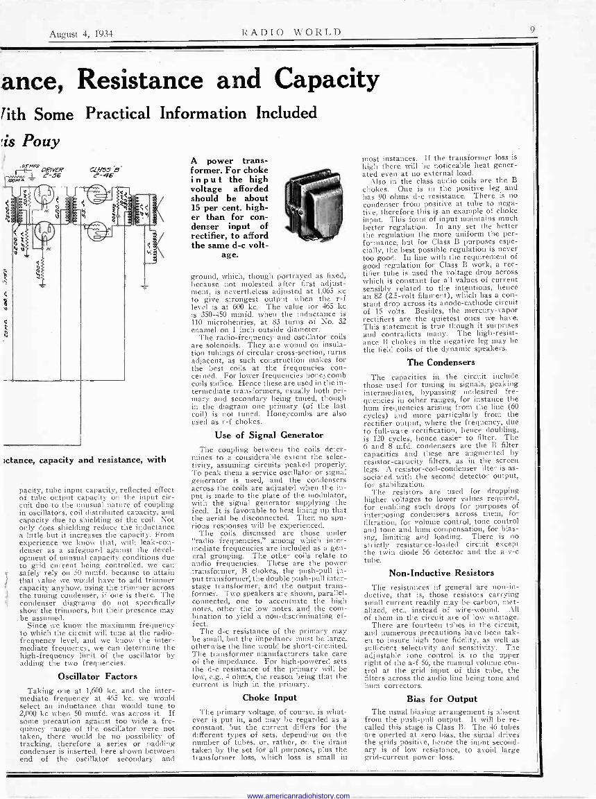
A power trans- former. For choke input the high voltage afforded should be about 15 per cent. high- er than for con- denser input of rectifier, to afford the same d -c volt-
age.
ground, which, though portrayed as fixed, because not molested after first adjust- ment, is nevertheless adjusted at 1,065 kc to give strongest output when the r -f level is at 600 kc. The value for 465 kc is 350-450 mmfd. when the inductance is 110 microhenries, at 83 turns of No. 32 enamel on 1 inch outside diameter.
The radio -frequency and oscillator coils are solenoids. They are wound on insula- tion tubings of circular cross-section, turns adjacent, as such construction makes for the best coils at the frequencies con- cerned. For lower frequencies honeycomb coils suffice. Hence these are used in the in- termediate transformers, usually both pri- mary and secondary being tuned, though in the diagram one primary (of the last coil) is not tuned. Honeycombs are also used as r -f chokes.
Use of Signal Generator The coupling between the coils deter-
mines to a considerable extent the selec- tivity, assuming circuits peaked properly. To peak them a service oscillator or signal generator is used, and the condensers across the coils are adjusted when the in- put is made to the plate of the modulator, with the signal generator supplying the feed. It is favorable to best lining up that the aerial be disconnected. Then no spu- rious responses will be experienced.
The coils discussed are those under "radio frequencies," among which inter- mediate frequencies are included as a gen- eral grouping. The other coils relate to audio frequencies. These are the power transformer, B chokes, the push-pull in- put transformer; the double push-pull inter - stage transformer, and the output trans- former. Two speakers are shown, parallel - connected, one to accentuate the high notes, other the low notes, and the com- bination to yield a non -discriminating ef- fect.
The d -c resistance of the primary may be small, but the ifpedance must be large, otherwise the line would be short-circuited. The transformer manufacturers take care of the impedance. For high-powered sets the d -c resistance of the primary will be low, e.g., 4 ohms, the reason being that the current is high in the primary.
Choke Input The primary voltage, of course, is what-
ever is put in, and may be regarded as a constant, but the current differs for the different types of sets, depending on the number of tubes, or, rather, on the drain taken by the set for all purposes, plus the transformer loss, which loss is small in
most instances. If the transformer loss is high there will be noticeable heat gener- ated even at no external load.
Also in the class audio coils are the B chokes. One is in the positive leg and has 90 ohms d -c resistance. There is no condenser from positive at tube to nega- tive, therefore this is an example of choke input. This form of input maintains much better regulation. In any set the better the regulation the more uniform the per- formance, but for Class B purposes espe- cially, the best possible regulation is never too good. In line with the requirement of good regulation for Class B work, a rec- tifier tube is used the voltage drop across which is constant for all values of current sensibly related to the intentions, hence an 82 (2.5 -volt filament), which has a con- stant drop across its anode -cathode circuit of 15 volts. Besides, the mercury-vapor rectifiers are the quietest ones we have. This statement is true though it surprises and contradicts many. The high -resist- ance B chokes in the negative leg may be the field coils of the dynamic speakers.
The Condensers
The capacities in the circuit include those used for tuning in signals, peaking intermediates, bypassing undesired fre- quencies in other ranges, for instance the hum frequencies arising from the line (60 cycles) and more particularly from the rectifier output, where the frequency, due to full -wave rectification, hence doubling, is 120 cycles, hence easier to filter. The 6 and 8 mfd. condensers are the B filter capacities and these are augmented by resistor -capacity filters, as in the screen legs. A resistor -coil -condenser filter is as- sociated with the second detector output, for stabilization.
The resistors are used for dropping higher voltages to lower values required, for enabling such drops for purposes of interposing condensers across them, for filtration, for volume control, tone control and tone and hum compensation, for bias- ing, limiting and loading. There is no strictly resistance -loaded circuit except the twin diode 56 detector and the a -v -c tube.
Non -Inductive Resistors The resistances hi general are non -in-
ductive, that is, those resistors carrying small current readily may be carbon, met- alized, etc., instead of wire -wound. All of them in the circuit are of low wattage.
There are fourteen tubes in the circuit, and numerous precautions have been tak- en to insure high tone fidelity, as well as sufficient selectivity and sensitivity. The adjustable tone control is to the upper right of the a -f 56, the manual volume con- trol at the grid input of this tube, the filters across the audio line being tone and hum correctors.
Bias for Output The usual biasing arrangement is absent
from the push-pull output. It will be re- called this stage is Class B. The 46 tubes are operted at zero bias, the signal drives the grids positive, hence the input second- ary is of low resistance, to avoid large grid -current power loss.
www.americanradiohistory.com

lo RADIO WORLD August 4, 1934
Neon Tube as Modulator Made to Give Big Wallop
By Jack Tully
.SO/"l.nfd.
D OZMA.
Ta«/p / Great increase in the intensity of the audio oscillation will result if the 0.00025 mfd. condenser at right is put across the 8.0-meg. limiting resistor instead of across the audio -oscillating neon lamp. The switch may cut the condenser in and out to provide modulated-unmodulated service on d.c. Other methods and uses pertaining to the neon tube are detailed in the text.
Z,Oda_/L
THE neon tube serves nicely as an audio oscillator for modulating a radio -frequency oscillator. The tube
may be used when the voltage is high enough, and even 90 volts would be suffi- cient, so batteries are not necessarily ex- cluded.
In general, however, for signal gener- ators the B supply is not more than 22.5 volts, or at most 45 volts, and neither volt- age is high enough to cause the tube to strike. Therefore audio transformers are used in battery -operated devices to pro- duce the modulation. This means either a regular tube is used for audio oscillator, with transformer, or one of the new com- bination tubes. If a combination tube is used the type filament that takes twice as much current as the standard filament for the series is greatly desired. As the 22volt series would be concerned, the 19 and the 106 would be used.
Oscillates on A.C. Too
Of course the 2 -volt series tubes are useful in signal generators for universal application (a.c., d.c and batteries), as a.c on the plate is satisfactory, besides pro- viding modulation. For introduction of the tone on d.c., the neon tube could be used, as, it will be noticed, the voltage is high enough, the line never being under 80 volts (let us hope), and only 62 volts being needed for "striking." Even on a.c. the neon tube oscillates at its own audio frequency, but this is drowned by hum.
The neon tube consists of two elements disposed in an evacuated space in which some neon gas has been left. When enough voltage is applied across the two plates, the gas breaks down, and the tube lights. Practically all lamps light with what passes for white light but the glow -
discharge tubes, so neon, argon and simi- lar tubes have distinctive colors. The very presence of these colors, each color dis- tinctive to the gas used, the difference in colors between lamps of the same class being unnoticeable to the human eye, at once suggests the presence of oscillation.
It may be said, without experimental confirmation, that the neon tube is oscil- lating at a frequency equal to that of the frequency of the orange color of the light it is exuding. This is not a form of oscil- lation that can be well communicated, ex- cept visually, but it is well to understand it as oscillation. The rapidity with which the gas is breaking down under the pres- sure of the voltage, that is, the rate of detachment of electrons from the gas, or rate of ionization, is the frequency of oscillation. It is one of the lowest light frequencies.
Condenser Across Resistor If we connect a resistor in series with
the lamp and put a condenser across the lamp, besides the light -frequency oscilla- tion, which is useful only for illumination, there will be another frequency of oscilla- tion, determined by the time constant of the circuit. The condenser across the lamp is well placed for a small amount of oscillation at this new frequency, for the conditions imposed require a relatively large capacity in this position, and natu- rally much of the oscillating current is bypassed around the lamp, and the total intensity of the audio oscillation is low. This in general may be desired, for avoid- ance of over -modulating a signal gener- ator. Then again some may prefer greater -far greater-intensity of audio oscilla- tion and wonder how it may be achieved without making any fundamental changes.
The solution is very, very simple. In-
stead of putting the condenser across the lamp, put it across the limiting resistor. In the diagram this limiting resistor is 8 meg., so that the condenser could be kept low (0.00025 mfd.), but if the condenser is put across the resistor, the resistor may be as low as 2 meg. and the frequency will be about 1,000 cycles.
Two extremes have been cited, that of weak intensity of audio oscillation in the neon tube, and that oi-strong intensity. Perhaps one desires to get between the two extremes. How would this be done? One way is to connect the lamp and its limiting resistor in series, with the con- denser across the limiting resistor (2 meg.), and put this series circuit across the filament limiting resistor of the 2 -volt tube. For the 30 tube this resistor, un- identified in the positive leg in diagram, is 1,700 to 1,750 ohms, 10 watts. Practi- cally the whole percentage of line voltage is dropped across this limiting resistor- all voltage but 2 volts-so there is plenty of voltage to energize the circuit.
Voltage and Frequency The neon tube should be tried for audio
purposes of this kind. It is also practical, in general, to vary the frequency either by changing the resistance or the ca- pacity. For resistance values it is per- haps best to consider fixed ones, for rather accurate work, and wire -wound fixed resistors at that. Then capacity can be accurately changed, as with a vari- able condenser. With 2.0 meg., across which was a variable condenser 6 to 80 mmfd., frequencies from 10,000 to 4,000 cycles were generated, and by using greater capacity, the range could be ex- tended to the lower desirable limit, say 50 cycles or so. The voltage should be the same always, if any calibration is to be repeated, for the neon tube is unstable, in the sense that terminal voltage changes the frequency.
Any neon tube may be used, even the smallest obtainable giving a strong ampli- tude when the condenser is across the limiting resistor, rather than across the lamp. Also, the range of oscillation fre- quencies is practically without limit. It is generally stated that the tube stops oscillating somewhere around 100 kc, but the circuits shown always have the con- denser across the lamp, whereupon the condenser detours practically all of the oscillation voltage at that frequency. Due to instability, higher frequencies are not so desirable, there being better tubes for such purposes, and besides there is diffi- culty in taking off these frequencies from neons due to the diode operation into to- tal supply voltage, but frequencies well above 100 kc are attainable, and, of course, so are frequencies to an extreme- ly low limit-practically to almost d.c. Frequencies were generated equal to 1-4, using a 8.0 mfd. condenser across 2.0 meg. The frequency of 1-4 means that there were one pulse every four seconds. At 110 volts the factor was 32 beats per min- ute per 1 mfd., proportionately fewer beats for higher capacities.
Capacity Measurement Therefore it will occur to many that
here is a method of measuring high ca- pacities, by relating them to the number of audio oscillations, which may be seen, for such high capacities, or may be heard. Always they may be heard, even until 10,000 cycles. If the voltage is held to a certain value, as it may be by adjustment and measurement prior to test, the un- known capacity may be measured either by comparing the resultant periodicity with the second hand of a watch, that is, actually counting the pulses per unit time, or by selecting some unit time such as 1 second, and having the adjustable re- sistance calibrated in terms of capacity. Or the voltage could be varied and the .
meter calibrated in capacity for truly cur- rent values.
www.americanradiohistory.com

August 4. 1934 RADIO WORLD 11
It's a Microphone Age That We're Living In
By Larry Hudson
na -
A double -button carbon microphone at left, and a French -phone type arm with microphone, at right.
THE invention of the microphone, or earphone in reverse, was one of the really important contributions to
radio. It comes under the present gen- eral classification of transducer, because of the change effectuated in the energy. The input to the microphone may be called mechanical, as descriptive of the rarefactions and condensations of air created by sound, while the output is
electrical, because consisting of varia- tions of current. An energizing battery ie used to augment the effect, to give the current larger magnitude, and thus im- prove the sensitivity, although some forms of microphone do not have this type of auxiliary, but may have an am- plifier before or after the microphone.
The most popular and most sensitive microphone is the carbon -granule type. The audio frequencies impressed on the diaphragm cause change in resistance of the carbon and therefore change in the current through the dielectric. The car- bon microphone is of the single -button or double -button type. A double -button microphone is illustrated as the circular one.
The Art Advances
Moreover, microphones may be of dif- ferent mechanical types, some for lapel - fastening, others for hand work, others to be put on stands or suspended from springs or from pulleyed lines, and others (as one illustrated) on a sort of tone arm.
The microphone technique has been de- veloped considerably since the first crude microphone was used. The quest always has been for better and better tonal re- sponse. The factor of sensitivity is, in general, not so important, for in high - quality pickup, as for studios and high- class public address work, low fields may be compensated for much more readily than poor tone, or unreasonably restrict- ed cutoff frequency limits.
Along the lines of tonal improvement the condenser microphone was developed. This is not a sensitive device by any means, and some say it is the least sensi- tive. Nevertheless it has been a great success, because of its faithful reproduc- tion. Its success has been a fitting con- trast to the failures of condenser type speakers, though the theory applying to both devices is the same. Probably the microphone engineers were a little more alert and resourceful than the speaker engineers.
Then came the ribbon microphone, or
so-called velocity microphone. This is the one on which the big play is being made at present for quality work. It is an expensive device, as usually made, and it serves exacting purposes, but even the smaller stations, and the medium-sized ones, too, don't seem to be able to afford one, or even a condenser microphone, and manage during a depression to get along with whatever they have.
The microphone is essential to broad- casting, not in the same class as the tube, nevertheless one of the .items in the in- dispensable class.
Home Uses Radio set users first became acquainted
with the microphone as a sort of toy. It was considered by some great fun to con- nect the microphone to the receiver so that one could cut out the program and cut in the microphone, making facetious or alarming announcements, and amusing
or consternating one's guests, until the joke was finally revealed. It was a sport attractive to the advocates of practical jokes, but as our juvenile academy teach- ers always told us that practical jokes never were in good taste, maybe the pub- lic knew that and therefore the sales of microphones for these kid -trick purposes did not thrive for that reason.
However, there are serious uses for the microphone at home. If baby is asleep in a distant room, a microphone connected to a transmission line and amplifier lets the whole house know if baby cries. This use is on the assumption that some babies when they awake crying do not make enough noise to be heard all over the house, although bachelors must have originated that idea, and particularly bachelors far removed from familiarity or even early association with baby - dominated households.
The microphone may be used in French -phone type, as shown, for inter - room communication in a house. Then batteries are used for auxiliary energy. The inter -office communication systems provide a considerable outlet for this type of microphone, but in the home the accessibility of the instrument should be elevated above the reach of young hands, as it is surprising how much five -year - olds have to say to each other over the home inter -room phone, while the bat- teries are being deplenished with no re- grets on the part of the juveniles.
Not So Polite The microphone also may be used by
the heavy -sleeping wife as an aid to de- termination when her husband is putting the key into the door after that trying club meeting, or for eavesdropping on neighbors, when the microphone is con- cealed, as in police work, and listening done in comfort in another room or house. This is not strictly polite but is practical.
Of course, all amateurs using phone need microphones, as they are in the same class as broadcasting stations in that respect, besides the whole sound - recording field, and sound reproduction field as well, constitutes a prolific source of microphone sale and use. In fact, we are living in the microphone age.
Two Almost the price of One Radio World Is $6.06 a year (52 issues). Read the following Combination Offers for Radio World
and other worth -while publications for one full year on each offer.
D RADIO WORLD and SHORT-WAVE CRAFT, $700. u RADIO WORLD and POPULAR SCIENCE MONTHLY $6.50. D RADIO WORLD and RADIO -CRAFT (monthly, 12 issues) $6.50.
RADIO WORLD and RADIO INDEX (monthly, 10 issues), stations, programs, etc., $6.35. RADIO WORLD and RADIO (monthly, 12 issues; Short Wave and Experimental) $6.60. RADIO WORLD and EVERYDAY SCIENCE AND MECHANICS (monthly) $6.50.
Q RADIO WORLD and RADIO LOG AND LORE. Bi -monthly; 5 issues. Full station lists, cross indexed, etc., $6.25.
RADIO WORLD and AMERICAN BOY - YOUTH'S COMPANION (monthly, 12 issues; popular magazine) $6.50.
RADIO WORLD and BOYS' LIFE (monthly, 12 issues) $6.50. RADIO WORLD and MOTION PICTURE MAGAZINE (monthly) $6.50.
D RADIO WORLD and MOVIE CLASSIC (monthly) $6.25.
D RADID WORLD and SCREENLAND (monthly) $6.50. RADIO WORLD and SILVER SCREEN (monthly) $6.25.
RADIO WORLD and THE PATHFINDER (weekly) $6.25. D RADIO WORLD and TRUE STORY (monthly) $6.50.
RADIO WORLD and LIBERTY (weekly) $6.50.
Select any one of these magazines and get it for an entire year by sending in a year's subscription for RADIO WORLD at the regular price, $6.00 plus a small additional amount, per quotations above. Put a cross in the square next to the magazine of your choice, in the above list, fill out the coupon below, and mail the quoted price by check, money order or stamps to RADIO WORLD, 145 West 45th Street, New York, N. Y. (Add $1.50 for extra foreign or Canadian postage for both publications.)
Your Name
Your Street Address
City State
If renewing an existing or expiring subscription for RADIO WORLD, please put at beginning of this sentence. If renewing an existing or expiring subscription for other magazines, please put at the beginning of this sentence.
RADIO WORLD, 145 West 45th Street, New York. (Just East
DOUBLE
VALUE!
a cross in square
a cross in square
of Broadway)
www.americanradiohistory.com

1' RADIO WORLD August 4, 1934
Fixed Bias is the Best; "C" Rectifier is
By Al Branch TH E biasing
method has a great deal to
do with the tone quality of a re- reiver. This method applies to the audio tubes, particularly to the output stage.
The methods usually employed are :
(1)-Interposing a resistor in the cathode leg of a -c tubes, or d -c tubes of the heater type, so that the plate current of the controlled tubes determines t h e bias. This pro- duces negative feedback. A large condenser across the biasing resist- or is necessary, except where (there is a com- mon resistor for two push-pull tubes, when no condenser is nec- essary. This ca- t h o d e- resistor method is called self - bias, and, where a condenser is needed, unless the capacity is enormous the method is n o t good. At best, the power output is limited:
(2)-Semi - fixed bias is a combin- ation of the cath- ode -resistor meth- od of self bias, with auxiliary bias from some steadier source, that is, where the audio signal amp- litude does not affect the bias so much. A choke in the negative leg of the recti- fier represents this. choke a resistor may be
Lauded
C {I TO A -F INPUT
TYPE 56
115V. A.C.
o 1.0
AMP.
R
F
e CIRCUIT WITH SEMI -FIXED BIAS
S-77 TYPE 2A3 l
FI
C4j- 10
FI R8
F2
F2
TYPE 5Z3
TYPE 2A3
S-105
0 p a o o
80 MA.
FIG.I
I80 MA.
371V. C3 302V.
2
ál) \ LI (5-26)
140MA. 1 44 i
CIRCUIT WITH FIXED BIAS TYPE + S-77 2Á3
APPROXIMATE VALUES
C1= BLOCKING CONDENSER -0.01 f C2= BY-PASS CONDENSER-0.25,Uf C3_ FILTER CONDENSER -10 p f C4 -BY-PASS CONDENSER -5 Ji.lf C5= BY-PASS CONDENSER -0.0511f c6= FILTER CONDENSER -5)1f LI = FILTER CHOKE -I0 HENRIES AT
MAX. MA.,60 OHMS L2=SPEAKER FIELD -430 OHMS L3= SPEAKER FIELD -1600 OHMS R1=5000 OHMS
362.5V. T `6T R4
1 L il _t_
+é TO
OTHER STAGES OF RECOVER
-B
TO OTHER
STAGES OE RECEIVER
-B
R2=200000 OHMS R3=10000 OHMS R4 =BLEEDER R5 =50000 OHMS R6=22000 OHMS R7 = CENTER -TAPPED
POTENTIOMETER 2500 OHMS R8 =POTENTIOMETER -100 OHMS R9 =0.5 TO 1.0 MEGOHM R10=2700 OHMS
Semi -fixed bias and fixed bias in high-powered push- pull output circuits.
Instead of a used. In gen-
eral, the method is excellent, because the higher the signal amplitude the greater
the current and the greater the bias, without the signal being a 'large contri - butant to the amount of bias. There is some positive feedback.
(3)-Fixed bias consists of using bat- teries or having a separate small rectifier tube that supplies the bias. Fixed bias is best, of course.
Say! Use 100 Mfd! The self -bias method is the easiest way,
and in small receivers, or installations where not much demand as to tone is im- posed, may be used. But if the condenser is very large, as stated, the tone becomes good enough. Practically, the condenser never can be too large. A capacity of 100 mfd. would be quite acceptable.
Semi -fixed bias works best with tubes that require relatively small bias, because then the amount of bias voltage is a smaller percentage of the total voltage across the choke that is the field of the speaker, usually. Sometimes a tapped field is used, and then, if the bias is obtained from 300 ohms, the rest of the d -c resist- ance of the field may be around 1,500 ohms. Such a condition would prevail for the pentode tubes, 2A5, 47, etc. The d -c resistance of the biasing section is only one -sixth of the total d -c resistance of 1,800 ohms, therefore hum trouble, from t&king off the bias from a part of the circuit where filtration is not complete, is not serious.
Where tubes are used that require much more bias voltage, the drop should be in about the same proportion, for the same small hum, and that is not so practical.
Splitting the Chokes However, the biasing part of the choke
system may be in the negative leg and the main filtering part in the positive leg, as in the upper diagram, and then the same condition is approximated, as to low hum, as obtained in the cited example of the biased pentode.
The 26 tube is the rectifier for the sep- arate C supply in the lower diagram. This is an excellent method. A tube must be used that starts working at once, par- ticularly with power tubes of the filament type, which also start at once. A heater type tube for the biasing, and especially with filament type power tube, would not be acceptable, because for from 6 to 12 seconds the immediately -starting high - emission filament type tubes, such as the 2Á3's, would be left with practically little bias, and high plate voltage. Thus the power tubes might be seriously injured, if not ruined.
It is surprising that so little popularity has been won by the separate C supply, for it represents possibilities for highest power output, comparable to battery bias, and besides there is no common imped- ance to obstruct the performance, since no signal current flows through the recti- fier or biasing circuit. When there is no signal through the biasing adjunct con- ditions are at their best in respect to tone.
Opinion Divided on Value of Push -Pull for R.F.
By L. Carter Wood There is disagreement about the advan-
tages of push-pull radio -frequency ampli- fication. One school of thought points out that high -frequency reception is fav- ored, because of the halving of the ef- fective capacities of the tubes in the tuned circuits. This fact is of course true. Where frequencies are very high v.s with
altra frequencies, the tube capacities may be a sizeable fraction of the total capacity in the tuned circuits, and halving the tube capacity counts. But even without the extra tube the capacity could be halved by a small condenser.
Tone is another point. In general, there is an impression, not without basis, that
push-pull favors excellent tone. This is applied usually to audio. But some ex- perimenters find that tone on short waves is better with push-pull radio -frequency reception. However, very little construc- tion is done in the push-pull line for radio frequencies, especially as the cost per stage is practically doubled. The plain type of push-pull method is scarce- ly suitable for reception, rather for wave - meter work, as the sensitivity is too low. No regeneration is included, as it would have to be, to make the circuit suitable for general reception. But there is no doubt that, if regenerative, results to around 5 meters are attainable.
About the only ones who devote some time to push-pull radio -frequency circuits are the amateurs, and they have developed excellent cross -neutralized ones.
www.americanradiohistory.com

August 4, 1934 RADIO WORLD 13
If the current is small a resistor may be used instead of a B supply choke in a short-wave set, and filtration may be sufficient, due to the large capacity of the filter condensers. In this instance the current would not exceed 8
milliamperes under conditions of feedbless feedback.
Plate Voltage Control for Screen Grid Regenerators
By Charles Foller RADIO has been subjected to the sever-
est forms of economizing since the very beginning. Some manufacturers and experimenters have striven for the best results and have not counted the expense as an important item. But enough others have tried to cut every conceivable cor- ner. It is surprising how well the econom- izers have succeeded, measuring success by the attainment of the ends which they sought. They have succeeded in endow- ing radio with the universal broadcast re- ceiver that sells for $10 or so, complete with tubes, or inflicting this specimen on the public, whichever way you look at it, and they have minimized the number of coils, tuned circuits, filter circuits, tubes and the like, and reduced some chasses to little more than the cadmium -plated iron of which they are made. The radio part has seemed not much more than the mere supporting metal of the framework.
Some one found that a resistor could be used to replace a choke coil in the B supply of a universal short-wave set, a good set by the way. The resistor is sat- isfactory only if the current is very small. A capacity is more effective in series with such a resistor than in series with a semi -conductor, so with 25,000 ohms and two 8 mfd. condensers passable filtration is achieved.
Screen Voltage Control The plate current in the short-wave
universal circuit diagramed herewith is less than 2 milliamperes, therefore the resistor replacing the choke is permissible.
The suppressor is grounded and the screen voltage is varied for control of regeneration. This is an effective method of contrai, as in screen grid tubes the mutual conductance, or transconductance, to give it the preferred name, depends largely on the screen voltage. In fact, the plate current is practically indepen- dent of the plate voltage and depnds on the screen voltage. If the screen voltage is zero, the plate current is practically zero, though the plate voltage is the max- imum available.
Some experiments would be worth while, in the line of stabilization of a tube circuit, so that regeneration control would have minimum detuning effect, by alter- ing the plate voltage. The point may be raised that since the plate current does not depend on the plate voltage so much as it does on the screen voltage that the control would be insufficient. That would be true if the tickler were just taken at random, but where the tickler is made small, and the variation of current, hence control, is small, a working range can be found for each band.
Then the frequency stability of the system may be improved, that is, regen- eration has a minimum detuning effect, and frequency calibration even of a re- generative receiver becomes more prac- tical.
Antenna Condenser Of course a series antenna condenser,
if adjustable, as it should be, would work against the calibration, but for purposes
37
.5W an regeneralion
control
of finding particular frequencies, the cir- cuit could be used and calibrated in its oscillating condition, as with control set for maximum oscillation, and then the station could be followed through by tun- ing readjustment to compensate for the detuning caused by recession to just be- low the oscillation point.
A COMBINATION OFFER! RADIO WORLD and "RADIO NEWS"
$7.00 Canadian and Foreign, $1.50 extra.
You can obtain the two leading radio technical magazines that cater to experimenters. service men and students, the first national radio weekly and the leading monthly for one year each, at a saving of $1.50. The regular mall subscription rate for Radio World for one year (52 weeks). RAD10 WORLD. 145 West 45th Street, New York. N. _Y. Is $6.00. Send in $1.00 extra, net "Radie News" also for a year-a new issue each month for twelve months. Total 04 issues for $7.00.
RADIO WORLD, 145 West 45th St., N. Y. C.
SHORT-WAVE MATERIAL Issue of May 26, 1934-Two-Tube Short -Wave
Battery Set, with Resistance Coupled Audio; Nine -Tube All -Wave Superheterodyne, with AVC; Modulation of Waves (Part III of "The Short - Wave Authority").
Issue of June 2, 1934-Calibration of Short -Wave Receivers (4 Charts); A Precision Calibration Process; Aerials for Short Waves (Part IV of "The Short -Wave Authuority").
Issue of June 9, 1934-Two Short -Wave Receivers Using 25Z5; Precision Calibration of High Fre- quencies; The 19 -Tube for Short Waves; Short - Wave Midget; Short -Wave Tuners (Part V of "The Short -Wave Authority").
Issue of June 16, 1934-Finding Frequencies in a Small Short -Wave Set; Tuning Charts for All Plug-in Coils; The Mascot "Two" Short -Wave Set; Types of Receivers Used for Bringing in Short Waves (Part VI of "The Short -Wave Authority"). 15e a copy; or start subscription with any one of
these issues.
Radio World, 145 W. 45th St., New York, N. Y.
www.americanradiohistory.com

1} RADIO WORLD August 4, 1934
Auto Sets Vie for First Place with All -Wavers
By Lyon Morchauser AUTOMOBILE sets have become
vastly important in radio. With all - wave receivers, they lead in sales.
That is, most radio sales have to do with nothing else than auto sets and all -wave sets.
Fashions are changing. Methods are improving. Naturally, one of the first con- siderations is the elimination of the use of B batteries. No heed need be given to eliminating the storage battery, because there is such a battery in every car, and there is a generator in the car, so that the experience of many autoists is that they charge their battery more than they discharge it, hence some car owners will be found who run in the daytime with lights on, to get rid of some of the ex- cess charge, or eradicate the possibility of injuring the battery by overcharging it.
Generators Improved A vibrator unit is one method of getting
B voltage from the A battery. The arma- ture is made to oscillate, and this oscilla- tion voltage is alternating and is fed into a rectifier tube, as shown in the diagram. After the rectification there has to be considerable filtration. Large enough fil- ter capacity and high enough inductance choke are required, because there is more trouble from hum in the vibrator type than in the generator type, although rid- dance of the trouble is not difficult.
The generator is in effect a motor. It costs more. Recent types are great im- provements over the earlier models. Care must be exercised to get a generator pro -
0.3 /qFD
CHASSIS
39
GNP.
250
0.3 MFD.
0.5 MFD
portioned correctly to the power used. That is, if the current or voltage is more than what the generator was intended to deliver, the filtration will not be good, nor will the genera- tor last so long. With proper selec- tion the generator has almost unlimit- ed life. A vibrator may get out of order sooner. There is no fixed rule. It depends a lot on what the manufacturer put into the device that he sells.
Remote Control Tuning The generators are rated usually for
voltage, because for given voltages the drain is pretty much standardized. There are 90 -volt, 135 -volt and 180 -volt genera- tors. On what basis the rating is made is not so important, so long as the use is consistent with the rating. Actually, the power is what counts, but when the current is pretty nearly standard, expres- sion of the voltage is approximate expres-
An automobile set with remote con- trol tuning unit.
'NYaL. CONTROL OM Re-esrE
h
á On
77
sion of the power. Power is the time rate of electric energy, or rate at which work is done by electricity.
Most auto sets have remote control tun- ing. That means there is a cable con- nected to the receiver, and that the tun- ing unit, volume control and switch may be on a single piece clamped to the steer- ing column. Other auto sets are self- contained, even unto speaker, and a cable is provided for connection to the power supply, which is the storage battery. It is this battery that runs generator or vibrator.
Some auto sets are universal, in the sense they may be used also in the home, and are made of such appearance as to be attractive in the home, as well as elec- trically suitable for home use. In some instances a special connector permits coupling to the a -c or d -c line in the house, whereas in the car the connection to another outlet for the 6 -volt storage battery.
If the car has a 12 -volt storage battery, which is unusual these days, either a spe- cial vibrator or motor generator should be obtained, or a limiting resistor used in connection with a 6 -volt type. The limit- ing -resistor type wastes a lot of power- half of that supplied.
Desirability of Set Every car owner should consider hav-
ing a radio in his automobile. Especially when one gets used to listening in to cer- tain 'programs does he feel disappointed if he is required to be driving his car at the time a favorite program is on the air. Then the auto set saves the day-or night.
Also, when one is interested in special events broadcast, such as results of sports, the auto set renders an important service. The old saw about danger to driving re- sulting because of the set in the car being turned on does not amount to anything. Practically no accidents occur when a set
(Continued on next page)
e
0. 3 /v/FD
PL
SIK ON VOL COAT1 /N REAJOTE PLUG FROM
5ET
42
5z
F/ELOCO/L useoM07
at Ähot B- GND
NalChen
TK FeeMiNArOR
A' hol
Circuit diagram of an automobile receiver, using a vibrator unit to dispense with B batteries. This unit has a rectifier tube associated with it. The receiver could have remote -control tuning, as shown in the other
illustration.
www.americanradiohistory.com

August 4, 1934 RADIO WORLD
Dead Spots a Live Issue; Restoratives Are Prescribed
By Leon H. Husband HJEAD spots are due to only one cause-absorption. They may arise because the antenna system is an
absorbing circuit for a particular fre- quency or some particular frequencies, which is not unusual. If the circuit is re- generative, should regeneration fail the absorption condition may be assumed, also, on the ground that the frequencies for which regeneration must be supplied are denied that supply. Usually reducing the capacity of a series antenna conden- ser will restore regeneration.
Other absorption conditions are present. An unusual one had to do with a regen- erative circuit using a 6 -volt heater type tube. The limiting resistor, that reduced the line supply voltage to the required heater voltage, was wire -wound, and in- ductive. Therefore this resistor acted as a choke at a critical frequency in one band, stopping reception. Tiis idea seems far-fetched, because the heater is sup- posed to be free from the radio -active part of the circuit. This, however, is a false assumption, for the cathode is coupled to the heater both thermally and capacitatively, and the effect of the limit- ing -resistor -choke proved beyond all doubt that this is true. Regeneration was restored when a small condenser was put across the limiting resistor, only 0.00025 mfd.
Not Too Much Capacity It is unwise to put a large condenser
across it, because when the circuit is used on a. c. the large condenser has the effect of reducing the limiting resistance, be- cause a. c. passes through the condenser, and the heater voltage becomes too high. If the condenser is too large the heater will be burned out.
Another cause of absorption is current through coils not intended to be in use, that is, applying .particularly to switching systems. It is not true that switching systems necessarily account for many dead spots, because the better grades of short-wave and all -wave receivers to -day, using switching systems, are free from dead spots. The solution lies in removing the connections from the coils, so they are free of switch contacts, except pos- sibly at the low -potential points. These points are represented by 'negative A and plus B, negative A being grounded usual- ly. In a -c circuits the grounded connec- tion might be heater center. If so, con- densers across the centering device should be used, mica ones preferably, capacities not necessarily large. This applies to all tubes used for all radio frequencies, par- ticularly high frequencies.
A method sometimes applied is to put a shorting connection across a coil. If this is done in such a way that current through the short is negligible the system is all right. But it should be remembered that if there is stray coupling, and a shorting wire is switched across a coil, the current through the short may be tremendous, and of course sufficient to impair or stop all reception. This con- dition would be obvious, and the remedy to apply would be to remove the coupling, as by proper shielding.
What a Short Is The voltage across the short is next to
nothing, but that does not mean the cur- rent is such. The voltage is so low, prac- tically zero, because of the low resistance or short. In fact, a short circuit is de- fined as zero potential difference. But if
there is current it may rise to enormous heights just because the resistance is so low, for it _is high resistance that limits current, and low resistance that allows current to attain high values.
Any filter circuits should have a low enough fundamental frequency of their own to avoid any possibility of being ab- sorption circuits of the type discussed. This requirement is fulfilled if the a choke is used that has large inductance, say, 10
millihenries or more, and the capacity across it, or to ground, is large in re- lationship to that inductance, say, 0.01 mfd. mica. It is always well to use mica condensers for short-wave filtration pur- poses, because they are non -inductive. Paper condensers may or may not be non-conductive, but usually will be in- ductive, as that,type is less expensive and more prevalent.
Resistors, as intimated, if wire -wound, may be inductive, usually are. They may be wound to be non -inductive, but this again is a special precaution, not often encountered. Hence if a biasing resistor is inductive and hasn't a large enough condenser across it, then absorption may be present, dead spots suffered again. Hence for all circuits in which there is high frequency the resistors preferably should be of the non -inductive type, e. g., carbon or metallized, an easy attainment for low wattages, say, 1 watt or less. Whereas, if the current is high, and an inductive resistor is used, then the resistor should be confined to a circuit where a large capacity may be put without much danger of absorption, such as a reducing resistor for limiting B voltage, and as a special precaution a small mica condenser is put across the large paper condenser, hence trouble becomes unlikely.
The B Supply Electrolytic condensers don't have much
inductance, but they may have a high im- pedance to short-wave frequencies, in fact, do have just that. Therefore again, a mica condenser should be put across electrolytics even when they are in the B supply, and also when they are used to bypass any biasing resistor serving the radio -frequency or even audio -frequency tubes.
Another source of absorption, encount- ered at frequencies higher than those us- ually tuned in, is due to the impedance of conductive pieces, such as condenser frames, switch brackets and arms, and the like. It is not generally known that what seems to be a short circuit for high
Set Gives Real Use In An Automobile
(Continued from preceding ,tage) is in operation in the car. Accidents are due to other causes. Too many drinks is one of them. Carelessness of pedestrians is another. Insouciance of children is a third. Reckless driving is perhaps the most important. Pedestrians wearing dark clothes, that autoists can't see at night, is a much more important cause of acci- dents than most persons imagine. Poor brakes contribute their share. Blowouts are not to be ignored. The radio set as a cause of accidents may be ignored. No driver is so distracted by radio listening that he is not alive to the necessities of the road. He is driving first, listening next.
frequencies may really be a sizeable im- pedance to them. Thus a piece of No. 18
wire about 3.5 inches long was found to be absorptive, in an oscillating field. A condenser was put across it to remove the absorptive effect.
Another equivalent cause of trouble is high contact resistance. This may be found in poor switches, especially types made two years ago or more. The re- cently -made switches are, in general, quite excellent, and one type in mind has a contact resistance of only 0.004 ohm, and besides has two tabs for connection to the rotor, hence if both tabs are used, and assuming that the contact resistance is the somewhat dependent on the rotor connection, as well as the tab connection at the particular switch points, even the low cited figure can be reduced by using both connections to rotor. This is much less, as it is, than the normal contact re- sistance of a tube in a socket, or a plug- in coil in a socket. There must be some contact resistance between prong and socket in any plug-in arrangement, and it is quite possible to have a coil -switch assembly of smaller contact resistance than a plug-in coil system. This sounds like strange doctrine, but it is a fact.
Below 10 Meters A còil-switch arrangement was perfect-
ed which provided excellent results, sus- tained oscillation where desired, in the 30 - megacycle region, which is higher than frequencies normally tuned in, being at and below 10 meters. Practically all pres- ent receivers are either dead in this region or the sensitivity is about one -tenth or less of what it is in the lowest -frequency region that the multi -band set covers.
As the frequencies become higher and higher, the difficulties increase, but they shift to other parts of the circuit. The inductance and the capacity of the wires connecting various parts in the r -f cir- cuit become wave traps and require spe- cial treatment. It sounds silly to talk of putting condensers across connecting wires, but this is becoming a regular practice, and even putting a condenser from rear to front plates of a ground - potential frame-and-crossarm assembly of a coil switch is standard with several man- ufacturers.
M these extraordinary high frequen- cies, somewhere near where usual tubes stop functioning, the geometry of the tube enters. Then the inductance and capacity of the assembly inside the tube become almost as important as the veloc- ity of the electrons.
Ultra -Frequency Effect At ultra frequencies, as is well known,
a limiting factor on the continuation of oscillation is the time of transit of elec- trons in the space stream. When this time approaches or equals the frequency of the tuned circuit the oscillation be- comes practically nil or stops altogether. This is another form of absorption, be- cause all the effect is concentrated on the space stream, the tube determines the frequency, along with the voltages of the supply, and there may be no feedback .be- cause the intended frequency -determining portion of the circuit is left without pos- sibility of performing its desired function. This is nothing more or less than absorp- tion and in fact describes what absorp- tion is just as well as does any other ex- ample. An absorption circuit is like a blotter that draws unto itself the fluid electricity of the high -frequency alternat- ing circuit.
Absorption may carry through to un- expected parts of the circuit. It is mere theory to say that radio frequencies are kept out of the audio channel. Plenty of r. f, gets into the a. f. Any one doubting it should measure the r. f. in some audio stage and find out. Therefore bypassing with small capacities across the audio line is sometimes unusually effective.
www.americanradiohistory.com
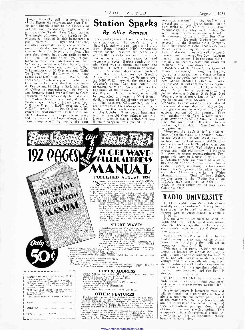
RADIO \V O R L D August 4, 1934
JACK PEARL, still masquerading as the Baron Munchausen, and Cliff Hall,
his man Sharlie, come to the listeners of WEAF each Wednesday night at 8:00 p. m., on the Tender Leaf Tea program. The music of Peter Van Steeden's Or- chestra is included in this broadcast; a good program. . . . Ryan and Noblette, erstwhile vaudeville stars, consider their jump to stardom on radio .a progressive step in the right direction; in fact, Tim says they should have gone radio sooner, and I think so, too! so will you, if you listen to these fine entertainers on their two weekly broadcasts, "Tim Ryan's Ren- dezvous," on Tuesdays, over an NBC- WJZ network, at 10:30 p. m.; and "Goin' To Town," with Ed Lowry, on Sunday evenings at 8 :00 p. m. . . . Eastern list- eners may now hear a program which has long been a fixture on the Pacific Coast- Al Pearce and his Happy -Go -Lucky Gang of California entertainers. This feature was formerly heard over a Coast -to -Coast network on Saturdays only, but now will be broadcast four times a week, Mondays, Wednesdays, Fridays and Saturdays, from 6:0o to 6:35 p. m. EDST over an NBC- WEAF network. . . . Frank Black, NBC general musical director, has left town for parts unknown; even his private secretary and his butler don't know where the fa- mous maestro will be during the next
Station Sparks By Alice Remsen
three weeks ; the truth is, Frank has gone on a vacation-and he doesn't want to be disturbed, and who can blame him! - . ,
Ford Bond, popular NBC announcer, whose baseball resumes are heard daily over NBC networks, has been in radio for twelve years as singer, announcer and program director. Before coming to the air, Ford was a choral conductor and played in Gilbert and Sullivan operettas.
An international short wave broadcast from Bayreuth, Germany, on Sunday, August 5th, will bring to listeners over an NBC-WJZ network the first act of Wagner's opera, "Das Rheingold." The performance of this opera will mark the beginning of the famous "Ring" cycle at the Bayreuth Music Festival,- which will be conducted this year by Karl Elmen- dorff, director of the Munich Staatsoper.
The Revelers, NBC quartet, who are real veterans in the radio game, will cele- brate their thirteenth anniversary on the air this October. They began broadcast- ing from the old Westinghouse studio in Newark, when it was a veritable triumph if their program was picked up by a
192 PAGES SNORT W,AVE FUDII(ADpRESS
MANUAL PUBLISHED AUGUST, 1934
{ { (1 HORT -WAVE and PUBLIC ADDRESS MANUAL" l\1 is an authoritative work, consisting of 192 pages,
5% x 8% Inches, bound in a cardinal red leather- ette cover, and containing contributions by leading special- ists on topics of utmost interest and importance to radio experimenters and service men.
The book contains technical articles about short-wave receivers and transmitters, with detailed discussion also of public address systems and valuable ideas on how to turn these systems into paying propositions. There are more than 400 illustrations, and many of these are pic-
torial diagrams of the wiring of short-wave and public address sets. Besides, the usual schematic diagram is always given for every set, and beau- tifully clear reproductions of photographs reveal the layout with realistic charm. Contributors include such distinguished authorities as William A. Bruno, Herman Bernard, Arthur II. Lynch, Lewis Winner, George R. Argabrite and Samuel Bagno. There are more than fifty topics, includ- ing the following:
SHORT WAVES Complete exposition of a complete assortment of
receivers, from one tube to 9 tubes, inclusive; battery, universal and a -c operation; regenerative sets and supera, with pictorial diagrams, schematic diagrams, full photographic illustrations and plain, easy -read text, with list of parts.
Portable Short -Wave Receivers. Design of Plug-in Coils, fully illustrated, with
pictures of the completed coils. Full winding data. Broadcast values Included.
Complete, up-to-date list of short-wave stations, with call letters, both wavelength and frequency, and HOURS ON THE AIR. Interference Elimination on Short Waves. Hum Elimination in Short -Wave Receivers. Wavelength -Frequency Conversion Table, useful for any frequencies, any wavelengths. The Morse Code and the International Code. Short -Wave Tuning Instructions. Short -Wave and All -Wave Antenna Systems. A 5 -to -10 -Meter Transceiver, with complete constructional details. This set will send and recd ce between these wavelength limits.
RADIO WORLD 145 W. 45th St N. Y.
Enclosed please find
fo$1 for which
eight weeks, send RADIO and malia mpos
WORLD postpaid for
a free premium "Short -Wave and Public I
I Address Manual." I
I as copyfor of which "Short -Wave send
me and Publicd
I dress Manual."
Put check mark in appropriate square
I I
NAME
ADDRESS I
I CITY STATE I
I
PUBLIC ADDRESS Public Address Inste llat ions, How to Make Them, Requirements Are, and How to Fulfil Them. Power Transformers, Their Types and Uses. Portable Public Address Systems. Factors Governing Amplification In PA Systems. Modern Microphone Trends. Condenser and Velocity Microphones. Volume Controls. Curves, What They Mean and How to Use Them,
OTHER FEATURES Besides subject -matter strictly included within the title there are contributions on corrolary ,topics, including Service Oscillators, Broadcast Portable and Home Receivers of Various Types, Data Sheet for Electrolytic Condensers, to Enable Determination of Their ondition and Capacity: Testing Equipment, a General Treatise; Formulas and Data on Radio Receiver Components; Meters and Set Analyzers. This is strictly a text book and contains no advertising. Order your copy NOW as the edition is limited. Price, 50e per copy, postpaid, or sent free as a postpaid premium on receipt of a $1.00 subscription for RADIO WORLD (8 issues, one each week). Remit with order. Use coupon at left, if you like.
What the
Workman stationed on the roof with a crystal set. . . . Irene Bordoni has a new series on WEAF these days. Each Wednesday, Thursday and Friday, the scintillating French songstress is heard in the interests of the I. J. Fox Fur Com- pany. . Devorah Nadworney was selected by the Empire Gold Company for their "Voice of Gold" broadcasts over WEAF each Sunday at 1:45 p. m. ,
Everett Marshall lives in a walk-up apart- ment to keep his waist line down. Everett has nothing on me-I do the same thing- not only to keep my waist line down but i to keep the rent line down, too!
Producers of the "True Story Court of Human Relations," among the first to sponsor a program over a Coast -to -Coast Columbia network, have renewed the cur- rent series, becoming effective Friday, August 3rd. It will continue on its regular schedule at 8:30 p. m. EDST, each Fri- day. Percy Hemus continues as the Judge; the cast includes, Elsie Hitz, Ned Weaver, Ann Elstner, Lucille Wall, Al- lyn Joslyn and Paul Stewart. . . . Fred Waring's Pennsylvanian's have started their annual stage show and dance tour through the middle western and north- eastern sections of the country. They will continue their Ford Dealers broad- casts over the WABC-Columbia network from the road, and will return to the Radio Playhouse stand in New York early in September.
"Between the Book Ends," a quarter- hour of restful reading, a popular feature in the West and Middle West, can now be heard in the East over a WABC-Col- umbia network each Thursday afternoon at 5:15 p. m. EDST. Ted Malone reads poems and light philosophy and Howard Ely provides organ accompaniment. Pro- gram originates in Kansas City. . Al L. Alexander, chief announcer of WMCA, key station of the new American Broad- casting System, is taking his first vaca- tion in his ten years of broadcasting; he and Mrs. Alexander are in the White Mountains. . "Smiling" Jerry Baker, popular tenor of the "Radio Party" on WMCA each week -day at 5:00 p. m., EDS, is entertaining his in-laws from Columbia, Ohio.
RADIO UNIVERSITY IS IT all right to use 2 -volt tubes hori-
zontally or upside-down? I note heater type tubes may be used horizontally if the heaters are in perpendicular alignment. -J. H. M.
No, the 2 -volt tubes must be used up- right, and must not be used with series - connected filaments, either. They are not such sturdy tubes as to stand these im- provisations. * * *
WHY CAN NOT a neon lamp be in- cluded across the primary of an output transformer, so that it then will act as resonance indicator ?-I. H.
This use is not good, because the tube would be ignited by modulation only, a wobbly voltage source, causing the tube to go on and off. What is needed is direct voltage, and this is usually obtained from some resistor network that carries current to r -f tubes. At this stage the modulation has not been removed and the light is steady. * * *
WHAT IS MEANT by the short -cir- cuited -turn effect of a tuning condenser, and what is a precaution against it?- G. D. C.
If the condenser is inspected closely it will be found that a point may be traced along a complete conductive path. Start at the rear frame, mentally trace a path along the shaft to the front frame, and then at bottom perhaps along metal chassis to the rear starting point. This is equivalent to a short-circuiting turn. A remedy is to have an insulated bearing break this continuity.
www.americanradiohistory.com