MVP Plan of Development - Mountain Valley Pipeline · 2019-09-10 · Plan of Development Mountain...
78
Plan of Development Mountain Valley Pipeline Project Prepared by: November 30, 2017
Transcript of MVP Plan of Development - Mountain Valley Pipeline · 2019-09-10 · Plan of Development Mountain...

Plan of Development Mountain Valley Pipeline Project Prepared by:
November 30, 2017

Plan of Development Mountain Valley Pipeline Project
November 30, 2017 iii
TABLE OF CONTENTS 1.0 Purpose and Need .............................................................................................. 1-1
1.1 Project Overview .......................................................................................... 1-1 1.2 Project Purpose ............................................................................................ 1-5 1.3 Dimensions of the Right-of-Way and Related Facilities on Federal
Lands ........................................................................................................... 1-6 1.4 Existing Rights-of-Way ................................................................................. 1-7 1.5 Alternative Routes or Locations ................................................................... 1-7
2.0 Right-of-Way Location ....................................................................................... 2-1 2.1 Legal Description ......................................................................................... 2-1 2.2 Site-Specific Engineering Surveys for Critical Areas .................................... 2-2 2.3 Acre Calculation of the Right-of-way by Land Status ................................... 2-3
3.0 Facility Design Factors ...................................................................................... 3-1 4.0 Additional Components of the Right-of-Way ................................................... 4-1 5.0 Government Agencies Involved ........................................................................ 5-1 6.0 Construction of the Facilities ............................................................................ 6-1
6.1 Construction ................................................................................................. 6-1 6.1.1 Standard Construction and Restoration Techniques ......................... 6-4
6.1.1.1 Surveying and Staking ......................................................................6-5 6.1.1.2 Clearing and Grading ........................................................................6-5 6.1.1.3 Trenching ..........................................................................................6-7 6.1.1.4 Pipe Assembly ..................................................................................6-7 6.1.1.5 Hydrostatic Test and Final Tie-In ......................................................6-9 6.1.1.6 Cleanup and Restoration ..................................................................6-9 6.1.1.7 Construction in Rugged Terrain ...................................................... 6-10 6.1.1.8 Proposed Wetland and Waterbody Pipeline Construction ............... 6-13 6.1.1.9 Typical Road Crossings .................................................................. 6-17 6.1.1.10 Trail Crossings ................................................................................ 6-18 6.1.1.11 Typical Topsoil Segregation ............................................................ 6-18
6.1.2 Special Construction Procedures .................................................... 6-19 6.1.2.1 Blasting ........................................................................................... 6-19 6.1.2.2 Stove-Pipe Construction ................................................................. 6-20 6.1.2.3 Karst Area ....................................................................................... 6-21 6.1.2.4 Trench Dewatering .......................................................................... 6-21 6.1.2.5 Winter Construction ........................................................................ 6-22
6.2 Work Force ................................................................................................. 6-22 6.3 Communication Procedures and Notification Protocols ............................. 6-23 6.4 Roles and Responsibilities ......................................................................... 6-23
6.4.1 Federal Energy Regulatory Commission ......................................... 6-23 6.4.2 U.S. Forest Service and U.S. Army Corps of Engineers .................. 6-23 6.4.3 Compliance Inspection Contractor .................................................. 6-24 6.4.4 Mountain Valley Pipeline ................................................................. 6-25 6.4.5 Construction Contractor ................................................................... 6-25 6.4.6 Environmental Inspection ................................................................ 6-26

Plan of Development Mountain Valley Pipeline Project
November 30, 2017 iv
6.5 Access to and Along Right-of-way during Construction ............................. 6-28 6.5.1 Road Closures ................................................................................. 6-28 6.5.2 Road Improvements ........................................................................ 6-28
6.5.2.1 Pocahontas Road (FR #972) Construction Plan .............................. 6-28 6.5.2.2 Crossing Brush Mountain (FR #188) ............................................... 6-29 6.5.2.3 Road Reconstruction....................................................................... 6-30
6.6 Contingency Planning ................................................................................ 6-33 6.7 Safety Requirements .................................................................................. 6-33
7.0 Resource Values and Environmental Concerns .............................................. 7-1 7.1 Soils and Vegetation .................................................................................... 7-1 7.2 Exotic and Invasive Species Control ............................................................ 7-2 7.3 Water Quality ............................................................................................... 7-2
7.3.1 Stormwater Pollution Prevention ....................................................... 7-2 7.3.2 Spill Prevention, Containment, and Countermeasures ...................... 7-2 7.3.3 Impact Avoidance and Minimization .................................................. 7-2
7.4 Plant and Wildlife Conservation ................................................................... 7-3 7.5 Health and Safety ......................................................................................... 7-4
7.5.1 Blasting .............................................................................................. 7-4 7.5.2 Fugitive Dust Control ......................................................................... 7-5 7.5.3 Fire Prevention and Suppression ...................................................... 7-5 7.5.4 Hazardous Materials Management .................................................... 7-5 7.5.5 Construction Emergency Preparedness and Response .................... 7-5 7.5.6 Operations, Maintenance, and Emergency Response ...................... 7-5 7.5.7 Framework Flagging, Fencing, and Signage ..................................... 7-6
7.6 Cultural and Historic Resources ................................................................... 7-6 7.7 Unanticipated Discovery of Paleontological Resources ............................... 7-6 7.8 Off-Highway Vehicle Control and Access ..................................................... 7-6 7.9 Scenery Mitigation ........................................................................................ 7-7
8.0 Stabilization and Rehabilitation ........................................................................ 8-1 8.1 Restoration (Soil Replacement and Stabilization) ........................................ 8-1 8.2 Disposal of Vegetation Removed During Construction ................................ 8-1 8.3 Seeding Specifications ................................................................................. 8-2 8.4 Fertilizer ....................................................................................................... 8-2 8.5 Limiting Access to the ROW and Law Enforcement ..................................... 8-3 8.6 Access Road Reclamation ........................................................................... 8-3
9.0 Operation and Maintenance .............................................................................. 9-1 9.1 Access Needed for Operation and Maintenance .......................................... 9-2 9.2 Hydrostatic Testing During Operation .......................................................... 9-3 9.3 Removal or Addition of Infrastructure during Pipeline Maintenance ............. 9-3 9.4 Safety ........................................................................................................... 9-3 9.5 Will Industrial Wastes and Toxic Substances be Generated or Stored
on ROW ....................................................................................................... 9-3 9.6 Inspection and Maintenance Schedules ....................................................... 9-3 9.7 Work Schedules ........................................................................................... 9-3 9.8 Fire Control .................................................................................................. 9-4

Plan of Development Mountain Valley Pipeline Project
November 30, 2017 v
9.9 Contingency Planning .................................................................................. 9-4 10.0 Termination and Restoration .......................................................................... 10-1
10.1 Removal of Structures ................................................................................ 10-1 10.2 Obliteration of Roads ................................................................................. 10-1 10.3 Stabilization and Revegetation of Disturbed Areas .................................... 10-1
LIST OF APPENDICES Appendix A Map Appendix Appendix A-1 Alignment Sheets Appendix A-2 Conventional Bore Profiles Appendix A-3 Topographic Maps Appendix A-4 Exhibit Maps Appendix B Details Appendix Appendix C Erosion and Sedimentation Control Appendix C-1 West Virginia Erosion and Sedimentation Control Plan Appendix C-2 Virginia Erosion and Sedimentation Control Plan Appendix C-3 Erosion and Sedimentation Control Sheets Appendix D Spill, Prevention, Control and Countermeasure (SPCC) Plans
and Unanticipated Discovery of Contamination Plans Appendix D-1 SPCC Plan and Unanticipated Discovery of Contamination
Plan for Construction Activities in West Virginia Appendix D-2 SPCC Plan and Unanticipated Discovery of Contamination
Plan for Construction Activities in Virginia Appendix E Conventional Bore Contingency Plan for the Proposed
Crossing of the Appalachian National Scenic Trail Appendix F Landslide Mitigation Plan Appendix G Site Specific Design of Stabilization Measures in Selected High
Hazard Portions of the Route of the Proposed Mountain Valley Pipeline Project in the Jefferson National Forest
Appendix H Restoration Plan Appendix I Timber Removal Plan for the Jefferson National Forest Appendix J General Blasting Plan for Jefferson National Forest Appendix K Plan of Development, Restoration Plan, & Erosion and
Sediment Details Appendix L Karst Mitigation Plan Appendix M Winter Construction Plan Appendix N Environmental Compliance Management Plan Appendix O Plan for Unanticipated Historic Properties and Human Remains
for West Virginia and Virginia Appendix P Plan for Unanticipated Discovery of Paleontological Resources
Plan of Development Mountain Valley Pipeline Project
November 30, 2017 vi
Appendix Q Framework Construction Emergency Preparedness and Response Plan
Appendix R Framework for Operations, Maintenance, and Emergency Response Plan
Appendix S Exotic and Invasive Species Control Plan Appendix T Herbicide Usage Plan Appendix U Stormwater Pollution Prevention Plan Appendix V Plant and Wildlife Conservation Measures Plan Appendix W Fugitive Dust Control Plan Appendix X Fire Prevention and Suppression Plan Appendix Y Hazardous Materials Management Plan Appendix Z Framework Flagging, Fencing, and Signage Plan Appendix AA Off-Highway Vehicle Management Plan

Plan of Development Mountain Valley Pipeline Project
November 30, 2017 vii
LIST OF TABLES Table 1-1. Land Requirements for the Mountain Valley Pipeline Project on
Federal Land .................................................................................... 1-6 Table 1-2. Existing Corridors Adjacent to the Proposed Project ............................. 1-7 Table 2-1. Legal Description of the Federal Lands on the JNF and USACE-
Managed Lands ............................................................................... 2-1 Table 2-2. Acre Calculation of the Project Facilities (Access Road, Work
Spaces, and the ROW) by Land Status Management Prescription Area .............................................................................. 2-3
Table 3-1. Pipe Specifications ................................................................................ 3-1 Table 5-1. Agencies with Relevant Permit or Consultation Requirements .............. 5-1 Table 6-1. Proposed Pipeline Construction Spreads within the JNF and at the
Weston and Gauley Turnpike Crossing ............................................ 6-5 Table 6-2. Proposed Wetland Impacts within the JNF .......................................... 6-13 Table 6-3. Proposed Waterbody Impacts within the JNF ...................................... 6-15 Table 6-4. Bedrock Rippability and Possible Extent of Blasting on JNF ............... 6-19 Table 6-5. Relationship of Roles and Responsibilities of Various Parties ............. 6-27 Table 6-6. Pocahontas Road Temporary Widening .............................................. 6-29 Table 6-7. Pocahontas Road Culvert .................................................................... 6-30 Table 7-1 Time of Year Restrictions on Jefferson National Forest lands
crossed by the proposed Mountain Valley Pipeline. ......................... 7-4 Table 9-1. Inspection Schedule for Major Components of the Project .................... 9-2
LIST OF FIGURES Figure 1-1. Project Overview .............................................................................. 1-2 Figure 1-2. Proposed Route in the JNF .............................................................. 1-3 Figure 1-3. Proposed Route for the Weston and Gauley Turnpike Crossing ...... 1-4 Figure 6-1. Typical Pipeline Construction Sequence .......................................... 6-3 Figure 6-2. Stove-Pipe Construction ................................................................ 6-11 Figure 7-1. ROW Clearing Pattern for Vegetation Feathering Technique........... 7-8 Figure 7-2. Concept for Revegetation of the Right-of-Way ................................. 7-9

Plan of Development Mountain Valley Pipeline Project
November 30, 2017 viii
ACRONYMS AND ABBREVIATIONS ANST Appalachian National Scenic Trail API American Petroleum Institute ATWS additional temporary workspace Bcf/d billion cubic feet per day BLM U.S. Department of the Interior, Bureau of Land Management BMP best management practice Certificate Certificate of Public Convenience and Necessity CFR Code of Federal Regulations CIC Compliance Inspection Contractor E&SCP Erosion and Sediment Control Plan ECM erosion control matting EIA Energy Information Administration EPA U.S. Environmental Protection Agency FERC Federal Energy Regulatory Commission FS U.S. Department of Agriculture, Forest Service JNF Jefferson National Forest1 MP milepost MVP Mountain Valley Pipeline, LLC NFS National Forest System NPDES National Pollutant Discharge Elimination System OHV off-highway vehicle2 PHMSA U.S. Department of Transportation Pipeline and Hazardous Materials
Safety Administration Plan FERC’s May 2013 version of the Upland Erosion Control,
Revegetation, and Maintenance Plan POD Plan of Development Procedures FERC’s May 2013 version of the Wetland and Waterbody Construction
and Mitigation Procedures Project Mountain Valley Pipeline Project ROW right-of-way SHPO State Historic Preservation Office SPCC Spill Prevention, Control, and Countermeasure SSEAP Site-Specific Emergency Action Plan Tcf trillion cubic feet Transco Transcontinental Gas Pipe Line Company, LLC
1 Jefferson National Forest refers to the southern portion of the current George Washington & Jefferson National Forests
throughout this document. Originally two separate national forests, the JNF and the George Washington National Forest were administratively combined in 1995 and are administered as a single national forest unit.
2 OHV in this document refers generally to all types of motorized off-highway vehicles, including both street-legal and non-street-legal full-size vehicles, motorcycles, all-terrain vehicles, utility terrain vehicles, etc.
Plan of Development Mountain Valley Pipeline Project
November 30, 2017 ii
USACE U.S. Army Corps of Engineers USDOT U.S. Department of Transportation VDEQ Virginia Department of Environmental Quality WVDEP West Virginia Department of Environmental Protection

Plan of Development Mountain Valley Pipeline Project
November 30, 2017 1-1
1.0 PURPOSE AND NEED 1.1 Project Overview Mountain Valley Pipeline, LLC (MVP or Mountain Valley), a joint venture between EQT Midstream Partners, LP and affiliates of NextEra Energy, Inc.; Con Edison Gas Midstream LLC; WGL Holdings, Inc.; and RGC Midstream, LLC is seeking a Certificate of Public Convenience and Necessity (Certificate) from the Federal Energy Regulatory Commission (FERC) pursuant to Section 7(c) of the Natural Gas Act authorizing it to construct and operate the proposed Mountain Valley Pipeline Project (Project) located in 17 counties in West Virginia and Virginia. MVP plans to construct an approximately 303-mile, 42-inch-diameter natural gas pipeline. Per the definitions of 49 Code of Federal Regulations (CFR) § 192.3, the pipeline is considered to be a transmission line, which is also referred to as a trunk line. The proposed pipeline will extend from the existing Equitrans, L.P. transmission system and other natural gas facilities in Wetzel County, West Virginia to Transcontinental Gas Pipe Line Company, LLC’s (Transco) Zone 5 compressor station 165 in Pittsylvania County, Virginia. In addition to the pipeline, the Project will include approximately 171,600 horsepower of compression at three compressor stations currently planned along the route, as well as measurement, regulation, and other ancillary facilities required for the safe and reliable operation of the pipeline. A 3.6-mile-long segment of the Project will cross portions of the Jefferson National Forest (JNF) in Monroe County in southern West Virginia and in Giles, Craig, and Montgomery counties in southwestern Virginia. The JNF is managed by the U.S. Forest Service (FS) within the U.S. Department of Agriculture. Another 60-foot-long segment of the Project will cross the Weston and Gauley Bridge Turnpike Trail (Weston and Gauley Turnpike) in Braxton County, West Virginia, which is a historic, unpaved trail administered by the U.S. Army Corps of Engineers (USACE). Construction of the Project segments that cross the JNF and the Weston and Gauley Turnpike are anticipated to occur in 2018. (Figures 1-1 through 1-3). Under the Mineral Leasing Act, approval to cross land managed by two or more federal agencies is the responsibility of the U.S. Department of the Interior, Bureau of Land Management (BLM) through issuance of a Right-of-Way Grant. The pipeline will be buried at a depth of three feet, per the requirements of the U.S. Department of Transportation Pipeline and Hazardous Materials Safety Administration (PHMSA) regulations, 49 CFR Part 192. There will not be any aboveground appurtenances within the JNF or USACE property such as compressor stations, measuring stations, valve settings, rectifiers/anode beds, etc. However, there will be minor appurtenances within the JNF that include test stations and line markers, which will be entirely contained within the 50-foot operational right-of-way (ROW) as required by PHMSA’s regulations. This Plan of Development (POD) replaces all of the Draft POD’s that have been submitted to date and outlines the steps that must be followed during construction and operation of the Project on federal lands. The POD is an iterative document that will evolve throughout the design and implementation process. All versions of the POD, appendices to the POD, and supporting documents will contain the date of issuance on each page.

Plan of Development Mountain Valley Pipeline Project
November 30, 2017 1-2
Figure 1-1. Project Overview

Plan of Development Mountain Valley Pipeline Project
November 30, 2017 1-3
Figure 1-2. Proposed Route in the JNF

Plan of Development Mountain Valley Pipeline Project
November 30, 2017 1-4
Figure 1-3. Proposed Route for the Weston and Gauley Turnpike Crossing
Plan of Development Mountain Valley Pipeline Project
November 30, 2017 1-5
An electronic index of current appendices and supporting documents will be kept up-to-date by MVP and housed on the Project Web site to be established prior to the start of construction. It is the responsibility of all involved personnel from all parties to ensure that they are utilizing the current version of all documents. Should a Right-of-Way Grant be issued for the Project, the final POD will be incorporated into the Grant.
1.2 Project Purpose The pipeline will transport up to 2.0 million dekatherms per day of natural gas from the Appalachian Basin to growing markets in the mid-Atlantic and southeastern United States. The purpose of the Project is to provide timely, cost-effective access to supplies to meet the growing demand for natural gas for use by local distribution companies, industrial users, and power generation facilities in the mid-Atlantic, southeastern, and Appalachian markets. The Project will also provide the opportunity for unserved and underserved markets along the route to access natural gas supplies. For example, the routing of the project through the southwest Virginia area resulted in Roanoke Gas Company becoming a Project shipper and requesting a specific tap location to support its local distribution company system’s growth and expansion. Roanoke Gas Company’s involvement as a shipper and its site-specific delivery point are concrete evidence of MVP’s purpose and need to provide opportunities for economic growth and development along the route of the Project.
In recent years, the North American natural gas market has seen enormous growth in production and demand. The United States Energy Information Administration (EIA) estimates that total natural gas consumption in the United States will increase from 26.2 trillion cubic feet (Tcf) in 2013 to between 29.7 Tcf and 37.4 Tcf in 2040 (EIA 2015). The largest portion of this growth in gas demand is expected to occur in the electric generation sector, where natural gas consumption is expected to increase from 8.2 Tcf in 2013 to 9.4 Tcf in 2040 (EIA 2015).
In addition to increased demand for electricity due to steady population growth, a major driver behind this increase is the retirement of 40.1 gigawatts of coal-fired electric generation by 2025 due to stricter environmental rules (EIA 2015). On August 3, 2015, the U.S. Environmental Protection Agency (EPA) announced the Clean Power Plan, which is designed to reduce carbon pollution from power plants (EPA 2015). Additionally, the EPA issued its Final Carbon Pollution Standards for New, Modified, and Reconstructed Power Plants and proposed a Federal Plan and model rule to assist states in implementing the Clean Power Plan. In the final Clean Power Plan, the EPA identifies substituting increased electricity generation from lower-emitting existing natural gas plants for reduced generation from higher-emitting coal-fired power plants as one of the building blocks necessary to achieve the required emission reductions for affected power plants. In particular, it is expected that replacing coal-fired electric generation with natural-gas-fired generation will be higher in the southeast because southeastern power markets include some of the most expensive delivered coal prices in the United States. The Project will provide the Mid-Atlantic and southeastern markets with direct access to new gas supplies to meet this increased demand for natural gas and thereby help lower emissions.

Plan of Development Mountain Valley Pipeline Project
November 30, 2017 1-6
A sizable portion of natural gas production growth is occurring in the Appalachian Basin shale region. Appalachian Basin shale gas production has increased from 2 billion cubic feet per day (Bcf/d) in 2010 to over 15 Bcf/d in July 2014. The Project will provide for transportation of these prolific natural gas supplies to Station 165, the pooling point for natural gas in Transco Zone 5, where this natural gas can serve the growing demand for natural gas for use by LDCs, industrial users, and power generation facilities all along the Eastern seaboard.
1.3 Dimensions of the Right-of-Way and Related Facilities on Federal Lands
The ROW on the JNF will be approximately 3.6 miles long. The construction ROW will be generally 125 feet wide; however, the width has been reduced in some areas. The construction ROW will include approximately 52 acres (Table 1-1). There be also will be approximately one acre of additional temporary workspace (ATWS) on the JNF, which will be used for the temporary staging of equipment for special construction techniques, and 33.7 acres of existing FS roads for access during construction. ATWS and access roads that will support construction are shown on figures included in Appendix A-1. The operational ROW will be 50 feet wide, covering an area of approximately 22 acres. No equipment storage areas will be required in the JNF during operation. Access roads are expected to utilize approximately 21 acres during operation.
Table 1-1. Land Requirements for the Mountain Valley Pipeline Project on Federal Land
Facility Land Required for Construction
(acres) Land Required for Operation (acres)
JNF Crossing Pipeline a/ 51.35 21.69 Additional Temporary Workspace 0.90 0.00 Access Roads 30.93 19.98 ANST Bore 0.00 0.00 Weston and Gauley Turnpike Pipeline b/ 0.00 0.07 Additional Temporary Workspace 0.00 0.00 Access Roads 0.00 0.00 a/ Acreage based on maximum 125-foot-wide construction ROW and 50-foot-wide permanent ROW. b/ MVP will bore under the approximate 60-foot USACE Weston and Gauley Turnpike property. The total bore length will be approximately 130 feet.
The Weston and Gauley Turnpike crossing will be conducted via conventional bore resulting in no disturbance to USACE property. MVP will complete an approximate 130-foot bore that will retain an approximate 20-foot vegetative buffer on each side of the USACE property boundary. Crossing the Weston and Gauley Turnpike by bore and retaining a 20-foot vegetation buffer on each side will avoid short-term and long-term impacts to users of the Weston and Gauley Turnpike.
Plan of Development Mountain Valley Pipeline Project
November 30, 2017 1-7
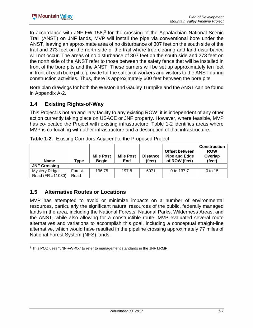
In accordance with JNF-FW-158,3 for the crossing of the Appalachian National Scenic Trail (ANST) on JNF lands, MVP will install the pipe via conventional bore under the ANST, leaving an approximate area of no disturbance of 307 feet on the south side of the trail and 273 feet on the north side of the trail where tree clearing and land disturbance will not occur. The areas of no disturbance of 307 feet on the south side and 273 feet on the north side of the ANST refer to those between the safety fence that will be installed in front of the bore pits and the ANST. These barriers will be set up approximately ten feet in front of each bore pit to provide for the safety of workers and visitors to the ANST during construction activities. Thus, there is approximately 600 feet between the bore pits.
Bore plan drawings for both the Weston and Gauley Turnpike and the ANST can be found in Appendix A-2.
1.4 Existing Rights-of-Way This Project is not an ancillary facility to any existing ROW; it is independent of any other action currently taking place on USACE or JNF property. However, where feasible, MVP has co-located the Project with existing infrastructure. Table 1-2 identifies areas where MVP is co-locating with other infrastructure and a description of that infrastructure.
Table 1-2. Existing Corridors Adjacent to the Proposed Project
Name Type Mile Post
Begin Mile Post
End Distance
(feet)
Offset between Pipe and Edge of ROW (feet)
Construction ROW
Overlap (feet)
JNF Crossing Mystery Ridge Road (FR #11080)
Forest Road
196.75 197.8 6071 0 to 137.7 0 to 15
1.5 Alternative Routes or Locations MVP has attempted to avoid or minimize impacts on a number of environmental resources, particularly the significant natural resources of the public, federally managed lands in the area, including the National Forests, National Parks, Wilderness Areas, and the ANST, while also allowing for a constructible route. MVP evaluated several route alternatives and variations to accomplish this goal, including a conceptual straight-line alternative, which would have resulted in the pipeline crossing approximately 77 miles of National Forest System (NFS) lands.
3 This POD uses “JNF-FW-XX” to refer to management standards in the JNF LRMP.

Plan of Development Mountain Valley Pipeline Project
November 30, 2017 2-1
2.0 RIGHT-OF-WAY LOCATION
2.1 Legal Description A legal description of federal lands on the JNF and USACE-managed lands crossed by the Project is presented in Table 2.1.
Table 2-1. Legal Description of the Federal Lands on the JNF and USACE-Managed Lands
Parcel Number Main Contact Legal Description
Title Comments
n/a Corps of Engineers, Huntington, West Virginia
A certain tract of land situated in the State of West Virginia, Braxton County, Salt Lick District, on the ridge between Barbecue Run and Clover Fork, tributaries of Knawl Creek and Oil Creek, respectively. Said tract is located entirely within a sixty (60) foot strip of land surveyed by the Corps of Engineers, Huntington, West Virginia, for a trail along the general alignment of the old Weston and Gauley Bridge Turnpike. Being the lands described in that certain Warranty Deed dated June 9, 1981, recorded in Deed Book 387 Page 778 of the records in the office of the County Clerk of Braxton County, West Virginia
No Assessor’s Parcel Number (APN) assigned
WV-MO-074
U.S Forest Service, George Washington & Jefferson National Forests, 5162 Valleypointe Parkway, Roanoke, VA 24019
Being the southern portion of that tract of land located near the top of Peters Mountain, in the Red Sulphur Magisterial District, of Monroe County, West Virginia. Being the lands described in that certain Warranty Deed dated October 10, 1988, recorded in Deed Book 183 Page 793 of the records of the office of the County Clerk of Monroe County, West Virginia
USA Forest Service Tract 1426. APN 03-35-7.1
VA-GI-002
U.S Forest Service, George Washington & Jefferson National Forests, 5162 Valleypointe Parkway, Roanoke, VA 24019
480.48 acres, more or less, Eastern District, in Giles County, Virginia, being the same lands described in that certain deed dated December 28, 1984, from National Gypsum Company to United States of America and recorded in Deed Book 187, Page 528 of the records in the office of the Circuit Court Clerk of Giles County, Virginia and further described in the plat dated July 27, 1983, and recorded in Deed Book 187, Page 533
USA Forest Service Tract 1130a. APN - 16-2
VA-GI-001
U.S Forest Service, George Washington & Jefferson National Forests, 5162 Valleypointe Parkway, Roanoke, VA 24019
102.83 acres, more or less, Pembroke Magisterial District, Giles County, Virginia, being the same lands described in that certain Warranty Deed dated December 5, 1983, from American Resources, Inc. to the United States of America and recorded in Deed Book 182, Page 717 of the records in the office of the Circuit Court Clerk, Giles County, Virginia
USA Forest Service Tract 1169a APN - 16-3B
Plan of Development Mountain Valley Pipeline Project
November 30, 2017 2-2
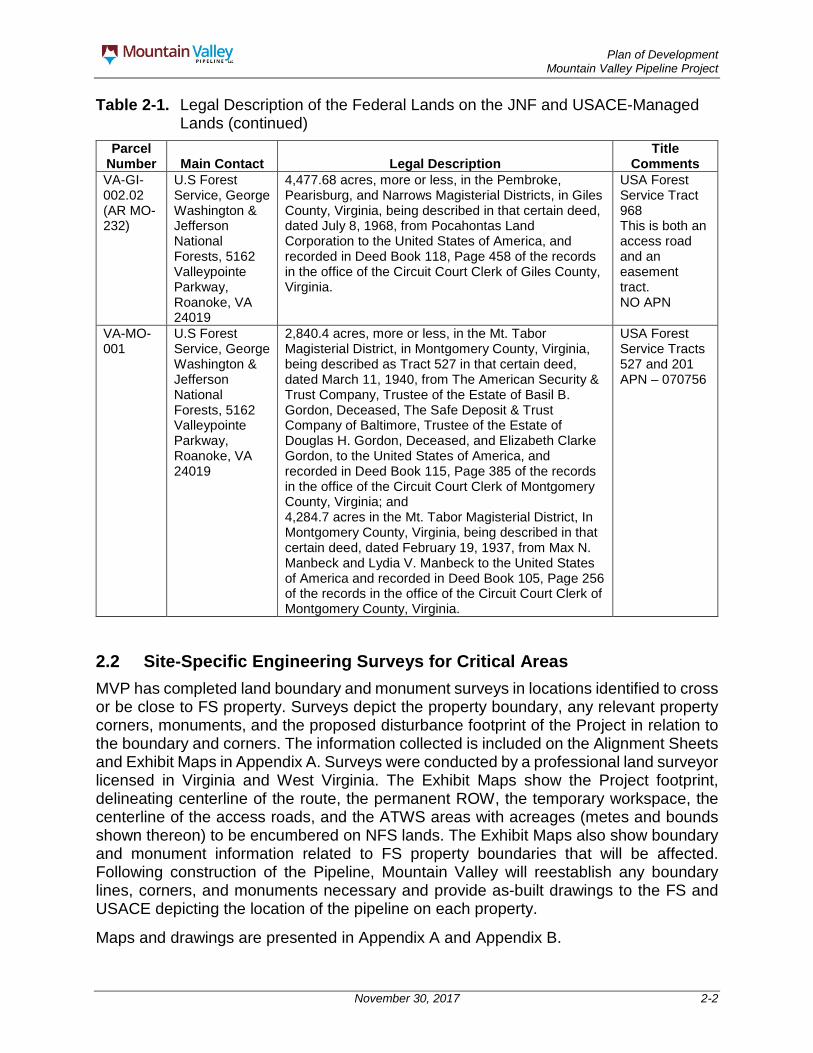
Table 2-1. Legal Description of the Federal Lands on the JNF and USACE-Managed Lands (continued)
Parcel Number Main Contact Legal Description
Title Comments
VA-GI-002.02 (AR MO-232)
U.S Forest Service, George Washington & Jefferson National Forests, 5162 Valleypointe Parkway, Roanoke, VA 24019
4,477.68 acres, more or less, in the Pembroke, Pearisburg, and Narrows Magisterial Districts, in Giles County, Virginia, being described in that certain deed, dated July 8, 1968, from Pocahontas Land Corporation to the United States of America, and recorded in Deed Book 118, Page 458 of the records in the office of the Circuit Court Clerk of Giles County, Virginia.
USA Forest Service Tract 968 This is both an access road and an easement tract. NO APN
VA-MO-001
U.S Forest Service, George Washington & Jefferson National Forests, 5162 Valleypointe Parkway, Roanoke, VA 24019
2,840.4 acres, more or less, in the Mt. Tabor Magisterial District, in Montgomery County, Virginia, being described as Tract 527 in that certain deed, dated March 11, 1940, from The American Security & Trust Company, Trustee of the Estate of Basil B. Gordon, Deceased, The Safe Deposit & Trust Company of Baltimore, Trustee of the Estate of Douglas H. Gordon, Deceased, and Elizabeth Clarke Gordon, to the United States of America, and recorded in Deed Book 115, Page 385 of the records in the office of the Circuit Court Clerk of Montgomery County, Virginia; and 4,284.7 acres in the Mt. Tabor Magisterial District, In Montgomery County, Virginia, being described in that certain deed, dated February 19, 1937, from Max N. Manbeck and Lydia V. Manbeck to the United States of America and recorded in Deed Book 105, Page 256 of the records in the office of the Circuit Court Clerk of Montgomery County, Virginia.
USA Forest Service Tracts 527 and 201 APN – 070756
2.2 Site-Specific Engineering Surveys for Critical Areas MVP has completed land boundary and monument surveys in locations identified to cross or be close to FS property. Surveys depict the property boundary, any relevant property corners, monuments, and the proposed disturbance footprint of the Project in relation to the boundary and corners. The information collected is included on the Alignment Sheets and Exhibit Maps in Appendix A. Surveys were conducted by a professional land surveyor licensed in Virginia and West Virginia. The Exhibit Maps show the Project footprint, delineating centerline of the route, the permanent ROW, the temporary workspace, the centerline of the access roads, and the ATWS areas with acreages (metes and bounds shown thereon) to be encumbered on NFS lands. The Exhibit Maps also show boundary and monument information related to FS property boundaries that will be affected. Following construction of the Pipeline, Mountain Valley will reestablish any boundary lines, corners, and monuments necessary and provide as-built drawings to the FS and USACE depicting the location of the pipeline on each property.
Maps and drawings are presented in Appendix A and Appendix B.

Plan of Development Mountain Valley Pipeline Project
November 30, 2017 2-3
2.3 Acre Calculation of the Right-of-way by Land Status Table 2-2 lists the acres within the construction ROW and ATWS by management prescription area identified in the Revised JNF Land and Resource Management Plan for the Jefferson National Forest (2004).
Table 2-2. Acre Calculation of the Project Facilities (Access Road, Work Spaces, and the ROW) by Land Status Management Prescription Area
Management Prescription Area1 Access Road ATWS Construction
ROW 4.A Appalachian National Scenic Trail 0.0 0.0 2.72 4.J Urban-Suburban Interface Area 0.0 0.0 14.1 6.C Old-Growth Forest 2.3 0.6 4.6 8.A.1 Mix of Successional Habitats 28.6 0.4 29.9
Total 30.9 1.0 51.3 Notes:
1. The acres shown in this table are GIS estimates. Numbers are not exact and columns may not sum correctly due to rounding.
2. Construction ROW in the area of 4.A does not include the acreage between the ANST bore pits.
Plan of Development Mountain Valley Pipeline Project
November 30, 2017 3-1
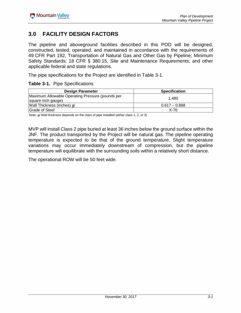
3.0 FACILITY DESIGN FACTORS
The pipeline and aboveground facilities described in this POD will be designed, constructed, tested, operated, and maintained in accordance with the requirements of 49 CFR Part 192, Transportation of Natural Gas and Other Gas by Pipeline; Minimum Safety Standards; 18 CFR § 380.15, Site and Maintenance Requirements; and other applicable federal and state regulations.
The pipe specifications for the Project are identified in Table 3-1.
Table 3-1. Pipe Specifications Design Parameter Specification
Maximum Allowable Operating Pressure (pounds per square inch gauge) 1,480
Wall Thickness (inches) a/ 0.617 – 0.888 Grade of Steel X-70 Note: a/ Wall thickness depends on the class of pipe installed (either class 1, 2, or 3)
MVP will install Class 2 pipe buried at least 36 inches below the ground surface within the JNF. The product transported by the Project will be natural gas. The pipeline operating temperature is expected to be that of the ground temperature. Slight temperature variations may occur immediately downstream of compression, but the pipeline temperature will equilibrate with the surrounding soils within a relatively short distance.
The operational ROW will be 50 feet wide.

Plan of Development Mountain Valley Pipeline Project
November 30, 2017 4-1
4.0 ADDITIONAL COMPONENTS OF THE RIGHT-OF-WAY
The pipeline will not connect to any existing pipeline ROW on the JNF or on USACE managed lands. Table 1-2 shows other corridors adjacent to the proposed pipeline ROW. No additional components are proposed for future development on either the JNF or USACE-managed lands. There will be no pumping, metering, compressor stations, mainline valves, or cathodic protection sites on either the JNF or USACE-managed lands. ATWS that will be utilized for equipment staging areas and other construction-supporting activities are shown on the Alignment Sheets included as Appendix A-1. There will be no ATWS required during operation. Mountain Valley also intends to utilize both Pocahontas (FR #972) and Mystery Ridge (FR #11080) roads during construction and operation of the Pipeline. MVP will not use Brush Mountain Road (FR #188) for construction or operation traffic. Signage will be posted during construction letting construction traffic know that Brush Mountain Road cannot be utilized. A discussion of road upgrades and maintenance can be found in Section 6.5.
Plan of Development Mountain Valley Pipeline Project
November 30, 2017 5-1
5.0 GOVERNMENT AGENCIES INVOLVED
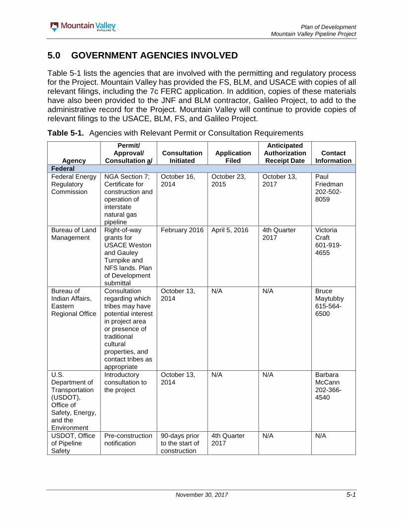
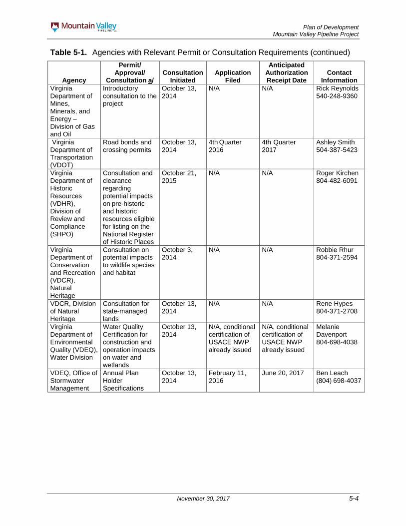
Table 5-1 lists the agencies that are involved with the permitting and regulatory process for the Project. Mountain Valley has provided the FS, BLM, and USACE with copies of all relevant filings, including the 7c FERC application. In addition, copies of these materials have also been provided to the JNF and BLM contractor, Galileo Project, to add to the administrative record for the Project. Mountain Valley will continue to provide copies of relevant filings to the USACE, BLM, FS, and Galileo Project.
Table 5-1. Agencies with Relevant Permit or Consultation Requirements
Agency
Permit/ Approval/
Consultation a/ Consultation
Initiated Application
Filed
Anticipated Authorization Receipt Date
Contact Information
Federal Federal Energy Regulatory Commission
NGA Section 7; Certificate for construction and operation of interstate natural gas pipeline
October 16, 2014
October 23, 2015
October 13, 2017
Paul Friedman 202-502-8059
Bureau of Land Management
Right-of-way grants for USACE Weston and Gauley Turnpike and NFS lands. Plan of Development submittal
February 2016 April 5, 2016 4th Quarter 2017
Victoria Craft 601-919-4655
Bureau of Indian Affairs, Eastern Regional Office
Consultation regarding which tribes may have potential interest in project area or presence of traditional cultural properties, and contact tribes as appropriate
October 13, 2014
N/A N/A Bruce Maytubby 615-564-6500
U.S. Department of Transportation (USDOT), Office of Safety, Energy, and the Environment
Introductory consultation to the project
October 13, 2014
N/A N/A Barbara McCann 202-366-4540
USDOT, Office of Pipeline Safety
Pre-construction notification
90-days prior to the start of construction
4th Quarter 2017
N/A N/A

Plan of Development Mountain Valley Pipeline Project
November 30, 2017 5-2
Table 5-1. Agencies with Relevant Permit or Consultation Requirements (continued)
Agency
Permit/ Approval/
Consultation a/ Consultation
Initiated Application
Filed
Anticipated Authorization Receipt Date
Contact Information
National Park Service (NPS) Southeast Region Blue Ridge Parkway
Consultation regarding potential impacts to the Blue Ridge Parkway
October 13, 2014
N/A N/A Bambi Teague 828-348-3439
Cultural Resource Survey Permission on NPS Lands
March 20, 2015; November 13, 2015; June 2, 2016; October 17, 2016
May 27, 2016; June 14, 2016
Survey Permission on NPS lands
April 24, 2015; November 13, 2015; January 13, 2016; June 1, 2016; October 17, 2016
May 25, 2016
ROW through NPS lands
November 10, 2016
4th Quarter 2017
NPS, Northeast Region, Appalachian Trail Park Office (NPS-APPA) for the ANST b/
Consultation regarding potential impacts to the ANST
October 13, 2014
N/A N/A Wendy Janssen 304-535-6279
USACE, Huntington District
Section 404 Permit for impacts on waters of the U.S., including wetlands Section 10 Permit for activities affecting navigation
October 13, 2014
February 21, 2016; update February 17, 2017
4th Quarter 2017
Christopher Carson 304-399-5819
USACE, Norfolk District
Same as USACE, Huntington District
October 13, 2014
February 21, 2016; update September 11, 2017
4th Quarter 2017
Todd Miller 804-323-3782
USACE, Pittsburgh District
Same as USACE, Huntington District
October 13, 2014
February 21, 2016; update February 17, 2017
4th Quarter 2017
Josh Shaffer 412-395-7121
U.S. Department of Agriculture (USDA), Virginia
Consultation regarding organic farmland
October 13, 2014
N/A N/A John David Harper 804-287-1736
USDA, West Virginia
Same as USDA, Virginia
October 13, 2014
N/A N/A Joe Hatton 304-284-7564

Plan of Development Mountain Valley Pipeline Project
November 30, 2017 5-3
Table 5-1. Agencies with Relevant Permit or Consultation Requirements (continued)
Agency
Permit/ Approval/
Consultation a/ Consultation
Initiated Application
Filed
Anticipated Authorization Receipt Date
Contact Information
EPA, Region 3 Air Protection Division
Project introduction and air permitting requirements
October 13, 2014
N/A N/A Diana Esher 215-814-2900
FS – Jefferson National Forest
Survey Permission on NFS lands
September 11, 2014
March 10, 2015; September 23, 2015; September 22, 2016; April 5, 2017
May 12, 2015; September 30, 2015; October 12, 2016; May 2, 2017
Jennifer Adams 540-265-5114
Cultural Resource Survey Permission on NFS lands
February 4, 2016; September 21, 2016; December 8, 2016
February 16, 2016; January 11, 2016
FS Plan Amendments and ROW Concurrence to the BLM
February 28, 2017
4th Quarter 2017
U.S. Fish and Wildlife Service, Virginia and West Virginia Field Offices
Consultation under Section 7 of ESA for potential impacts on federally protected species
September 24, 2014
N/A N/A Troy Andersen 804-824-2428 and Tiernan Lennon 304-636-6586 X12
Consultation regarding impacts on migratory birds and fish and wildlife
March 2015 N/A N/A
Biological Assessment/ Biological Opinion
March 2015 January 21,2016, June 2016, March 2016
4th Quarter 2017
Virginia Virginia Department of Forestry
Consultation regarding potential impacts to state-managed forests
October 13, 2014
N/A N/A Brad Williams 434-997-6555
Virginia Department of Game and Inland Fisheries (VDGIF)
Consultation regarding potential impacts to state-managed lands; Consultation for state threatened and endangered species
October 13, 2014
N/A N/A Ernie Aschenbach 804-367-2733
Plan of Development Mountain Valley Pipeline Project
November 30, 2017 5-4
Table 5-1. Agencies with Relevant Permit or Consultation Requirements (continued)
Agency
Permit/ Approval/
Consultation a/ Consultation
Initiated Application
Filed
Anticipated Authorization Receipt Date
Contact Information
Virginia Department of Mines, Minerals, and Energy – Division of Gas and Oil
Introductory consultation to the project
October 13, 2014
N/A N/A Rick Reynolds 540-248-9360
Virginia Department of Transportation (VDOT)
Road bonds and crossing permits
October 13, 2014
4th Quarter 2016
4th Quarter 2017
Ashley Smith 504-387-5423
Virginia Department of Historic Resources (VDHR), Division of Review and Compliance (SHPO)
Consultation and clearance regarding potential impacts on pre-historic and historic resources eligible for listing on the National Register of Historic Places
October 21, 2015
N/A N/A Roger Kirchen 804-482-6091
Virginia Department of Conservation and Recreation (VDCR), Natural Heritage
Consultation on potential impacts to wildlife species and habitat
October 3, 2014
N/A N/A Robbie Rhur 804-371-2594
VDCR, Division of Natural Heritage
Consultation for state-managed lands
October 13, 2014
N/A N/A Rene Hypes 804-371-2708
Virginia Department of Environmental Quality (VDEQ), Water Division
Water Quality Certification for construction and operation impacts on water and wetlands
October 13, 2014
N/A, conditional certification of USACE NWP already issued
N/A, conditional certification of USACE NWP already issued
Melanie Davenport 804-698-4038
VDEQ, Office of Stormwater Management
Annual Plan Holder Specifications
October 13, 2014
February 11, 2016
June 20, 2017 Ben Leach (804) 698-4037

Plan of Development Mountain Valley Pipeline Project
November 30, 2017 5-5
Table 5-1. Agencies with Relevant Permit or Consultation Requirements (continued)
Agency
Permit/ Approval/
Consultation a/ Consultation
Initiated Application
Filed
Anticipated Authorization Receipt Date
Contact Information
VDEQ, Office of Stormwater Management
Erosion and Sediment Control per 9VAC25-840 and the Virginia Erosion and Sediment Control Handbook. Stormwater Management per 9VAC25-870 and the Virginia Stormwater BMP Clearinghouse
October 13, 2014
Spread 8 - June 19, 2017; updated August 8, 2017 and November 1, 2017. Spreads 9 and 10 – September 21, 2017; update anticipated November 22, 2017. Spread 11 – September 11, 2017; update anticipated November 22, 2017.
4th Quarter 2017
Ben Leach (804) 698-4037
VDEQ Office of Water Supply
General Permit No. VAG83 for water discharge
January 13, 2016
March 22, 2016 N/A Anthony Cario 804-698-4089
VDEQ Office of Water Permitting
General Permit 9VAC25-200-10 for water withdraw
January 13, 2016
March 22, 2016 N/A Kip Foster 540 562-6782
Virginia Marine Resource Commission
Submerged Lands License
December 3, 2015
February 24, 2016; updated September 11, 2017
4th Quarter 2017
Randy Owen 757-247-2251
VDEQ, Office of Environmental Impact Review
Introductory consultation to the project
October 13, 2014
N/A N/A Julia Wellman 804-698-4326
Virginia Outdoors Foundation
Access or Utility Easement Application
June 2014 January 2016 4th Quarter 2017
Martha Little and Harry Hibbitts 504-332-8906
West Virginia West Virginia Department of Environmental Protection (WVDEP), Division of Air Quality
Air Quality permit for air emissions
October 10, 2014
N/A N/A Roy Kees 304-926-0499
Bradshaw Compressor Station
N/A October 21, 2015
March 14, 2016
Harris Compressor Station
N/A October 21, 2015
March 4, 2016
Stallworth Compressor Station
N/A October 21, 2015
April 11, 2016

Plan of Development Mountain Valley Pipeline Project
November 30, 2017 5-6
Table 5-1. Agencies with Relevant Permit or Consultation Requirements (continued)
Agency
Permit/ Approval/
Consultation a/ Consultation
Initiated Application
Filed
Anticipated Authorization Receipt Date
Contact Information
WVDEP, Division of Water and Waste Management
401 Water Quality Certification for construction and operation impacts on water and wetlands
October 10, 2014
February 25, 2016; December 1, 2016
March 23, 2017; Anticipated reissuance November 2017
Nancy Dickson (304) 926-0440
WVDEP Division of Water and Waste Management
Natural Streams Preservation Act Authorization for Greenbrier River
June 27, 2016 January 23, 2017; January 30, 2017
July 21,2017 Nancy Dickson (304) 926-0440
WVDEP, Division of Water and Waste Management
National Pollutant Discharge Elimination System (NPDES) Permit – Construction Stormwater General Permit for Construction Activities
October 13, 2014
February 23, 2016; update filed December 23, 2016
July 14, 2017; ; Anticipated reissuance November 2017
Joseph Cochran (304) 926-0440
WVDEP, Division of Water and Waste Management
NPDES Hydrostatic Test Discharge Permit
October 13, 2014
March 21, 2016 September 12 and 13, 2017
John Perkins (304) 926-0499
West Virginia Department of Highways
Road bonds and crossing permits
July 28, 2015 2nd Quarter 2016
4th Quarter 2017
Gary Clayton 304-476-4496
Notes: a/ Consultations will occur continuously throughout the development of the Project. b/ The National Trails System Act (NTSA) of 1968 (Public Law 90-543) designated the Appalachian Trail as the first National Scenic Trail and designated the National Park Service as the lead federal agency for the administration and management of the ANST. The Appalachian Trail Park Office (NPS-APPA) is the specific NPS administrative entity. The NTSA also stipulates that the NPS must work cooperatively with the FS, other public land-managing agencies, the Appalachian Trail Conservancy (ATC), and ATC-affiliated Local A.T. Clubs in the unique Cooperative Management System for the ANST.

Plan of Development Mountain Valley Pipeline Project
November 30, 2017 6-1
6.0 CONSTRUCTION OF THE FACILITIES
6.1 Construction MVP intends to implement all conditions outlined in the FERC Certificate, BLM Right-of-Way Grant, Revised JNF Land and Resource Management Plan for the Jefferson National Forest (2004), United States Army Corps of Engineers Nationwide Permit, and the WV and VA Erosion and Sediment Control Plans (E&SCP) (Appendix C) as minimum standards during construction. Construction is anticipated to begin in the fourth quarter 2017. MVP will provide a written request to proceed with construction to the BLM and FERC prior to the start of construction. The notice to proceed will be evaluated by the BLM (in coordination with the USACE and FS) and FERC. Construction will begin only after receipt of the notice to proceed from both BLM and FERC. MVP will ensure that construction personnel are adequately trained in the environmental restrictions and/or requirements applicable to their particular job duties. Anyone that will be on-site during construction of the Project will be required to have construction management and environmental training specific to the Project. Prior to the start of construction, the training presentation will be provided to the FS and BLM for review and comment. A log will be kept in the construction trailer documenting that everyone on-site during construction has participated in the necessary training sessions. It is not anticipated that hazardous waste will be generated or stored during construction of the Project. However, if for any reason hazardous waste is created or uncovered during construction or operation of the Project, the Spill Prevention, Control and Countermeasure (SPCC) Plan and the Unanticipated Discovery of Contamination Plan (Appendix D) would identify methods for handling the waste. All waste would be disposed of pursuant to state and federal requirements.
Construction of the pipeline will generate noise from heavy machinery and equipment as construction moves in phases along the ROW. Sound from pipeline construction will generally be temporary, sporadic, and short term in any one location along the pipeline route. Because of the temporary and daytime-only nature of pipeline construction activities, no special noise mitigation or noise monitoring is recommended during the construction phase.
MVP anticipates that it will employ the following procedures and standard equipment to construct the Project; however, deviations are possible based on actual field conditions or to comply with regulatory requirements. Mountain Valley does not intend to use any specialized equipment to construct the pipeline within NFS lands with the exception of a conventional auger bore machine. This piece of equipment will be utilized to bore under the ANST.
For the crossing of the ANST, MVP will install the pipe via conventional bore under the ANST, leaving an approximate area of no disturbance of 307 feet on the south side of the trail and 273 feet on the north side of the trail where tree clearing and land disturbance will not occur. The areas of no disturbance of 307 feet on the south side and 273 feet on the north side of the ANST refer to those between the safety fence that will be installed in front of the bore pits and the ANST. These barriers will be set up approximately ten feet in front of each bore pit to provide for the safety of workers and visitors to the ANST during construction activities. Thus, there is approximately 600 feet between the bore pits.

Plan of Development Mountain Valley Pipeline Project
November 30, 2017 6-2
MVP hired Rummel, Klepper and Kahl LLP, a design engineering firm that has expertise in trenchless crossing methods, to assess the different trenchless crossing options for the ANST. The two trenchless crossing methods considered were conventional bore and horizontal directional drill. The conventional bore method was determined to be feasible and the horizontal directional drill method was determined not to be feasible due to site-specific engineering constraints. MVP asked Rummel, Klepper and Kahl to further assess the specifics (such as location, length, route change, etc.) of the conventional bore options for the ANST. MVP examined the feasible conventional bore options and weighed the environmental impact, viewshed impact, and installation risks associated with each option. The selected conventional bore option is included in the updated alignment sheets and bore profile in Appendix A. The alignment sheet updates include aerial imagery; the buffer of 307 feet on the north side and 273 feet on the south side, totaling 580 feet for no vegetation clearing on either side of the trail; and conventional bore as the proposed construction crossing methodology for the ANST. No ATWS outside of the construction ROW will be needed for the conventional bore of the ANST. The portion of the ANST not included in the bore buffer (described above) will be marked as off-limits to all Project motorized use. However, Project personnel may walk between the bore pits during construction. Should the conventional bore under the ANST fail, MVP will notify and seek approval from FERC and FS to utilize the methods described in the Conventional Bore Contingency Plan for the Proposed Crossing of the Appalachian National Scenic Trail (Appendix E).
The crossing of the Weston and Gauley Turnpike will require an approximate 130-foot conventional bore outside of the USACE property boundary.
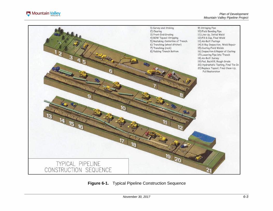
Construction of the Project will follow industry-accepted practices and procedures, as further described below. Generally, construction of the proposed pipeline will follow a set of sequential operations as shown in Figure 6-1. In this typical pipeline construction scenario, the construction spread proceeds along the pipeline ROW in one continuous operation. The entire process will be coordinated in such a manner as to minimize the total time a tract of land is disturbed and therefore be exposed to erosion and temporarily precluded from normal use. Alignment sheets showing facility locations are in Appendix A-1. MVP has created a set of scaled, typical drawings representative of terrain encountered within the JNF and are included as Attachment B. Drawings depict plans, profiles, and cross sections for flat to gently sloping terrain, wide ridges, sidehill construction with side slopes ranging from 3H:1V to 1.5H:1V, and narrow ridges with sideslopes ranging from 3H:1V to 1.5H:1V.
Plan of Development Mountain Valley Pipeline Project
November 30, 2017 6-3
Figure 6-1. Typical Pipeline Construction Sequence
Plan of Development Mountain Valley Pipeline Project
November 30, 2017 6-4
In practice, ridgetop construction will not require substantial excavation. Some material excavated from the ridgetop will be spread across the temporary ROW and some of the material will be stockpiled along the temporary ROW and replaced following construction. Following construction, the ridge will be recontoured as close to the original conditions as practicable. MVP will incorporate erosion and sediment control measures such as super silt fence, silt fence, sock filtration, erosion control socks, temporary and permanent water bars, ditch breakers, temporary mulch, and erosion control blankets as per Project design specifications based on slope. This is consistent with JNF-FW-10, which requires management activities that cause bare mineral soil on slopes greater than 5 percent to have erosion control planned and implemented.
Where stability issues have been identified, mitigation measures have been considered that include realignment of the pipeline to avoid areas of instability, deepening the pipeline below surface instability, buttressing, surface and subsurface drainage, rock bolting/soil anchors, surface stabilization matting, and regrading slopes to stable configurations as described in the Landslide Mitigation Plan, Appendix F and the Site Specific Design of Stabilization Measures in Selected High Hazard Portions of the Route of the Proposed Mountain Valley Pipeline Project in the Jefferson National Forest, Appendix G. In addition, maintaining proper drainage during construction and operation will help to maintain slope stability. The construction erosion and sediment control measures will be designed to avoid concentration of runoff onto or into steep areas prone to slope instability. Concentration of surface water will be discouraged through restoring the original grade as closely as practical and through use of water bars where necessary to divert surface flow off the ROW. These measures are consistent with JNF-FW-6, which requires management activities to be located and designed to avoid, minimize, or mitigate potential erosion. They are also consistent with JNF-FW-216, which requires that facilities be located, designed, and maintained to avoid, minimize, or mitigate potential geologic hazards. The anticipated location of different construction techniques along the Proposed route through the JNF are shown in Appendix B.
Also to minimize the impacts of construction disturbance, MVP will utilize FERC’s Plan and Procedures. The intent of FERC’s Plan and Procedures is to identify baseline mitigation measures for minimizing the extent and duration of Project-related disturbance on wetlands and waterbodies and enhancing revegetation. FERC’s Plan and Procedures are used as the “industry standard” and adherence to them is required unless a variance is requested by a state or federal land management agency. In addition, MVP will utilize its Project-specific E&SCP (Appendix C), as well as measures outlined in the POD. Equipment problems, terrain and soil conditions, and weather can affect the timing and consistency of the operation. The following sections provide detailed descriptions of each proposed construction method.
6.1.1 Standard Construction and Restoration Techniques MVP will conduct all construction activities in accordance with the conditions outlined in the FERC Certificate, BLM Right-of-Way Grant, JNF Land and Resource Management Plan, and WV and VA Erosion and Sediment Control Plans (Appendix C).
Following construction, the property will be returned to original contours except at those locations where permanent changes in drainage will be required to prevent erosion,
Plan of Development Mountain Valley Pipeline Project
November 30, 2017 6-5
scour, and possible exposure of the pipeline. Property boundary and monument markers that are removed will be replaced and remarked via civil survey based on the boundary surveys conducted and marked on the Alignment Sheets in Appendix A-1. The disturbed areas will be stabilized as outlined in the Restoration Plan included in Appendix H, which is consistent with JNF-FW-22, which requires the stabilization of all disturbed soil.
Those portions of the Project located primarily in upland terrain will employ conventional overland construction techniques for large-diameter pipelines. In the typical pipeline construction scenario, the construction contractor will construct the pipeline along the construction ROW using sequential pipeline construction techniques, including survey, staking, and fence crossing; clearing and grading; trenching; pipe stringing, bending, and welding; lowering-in and backfilling; hydrostatic testing; clean-up and restoration; and commissioning.
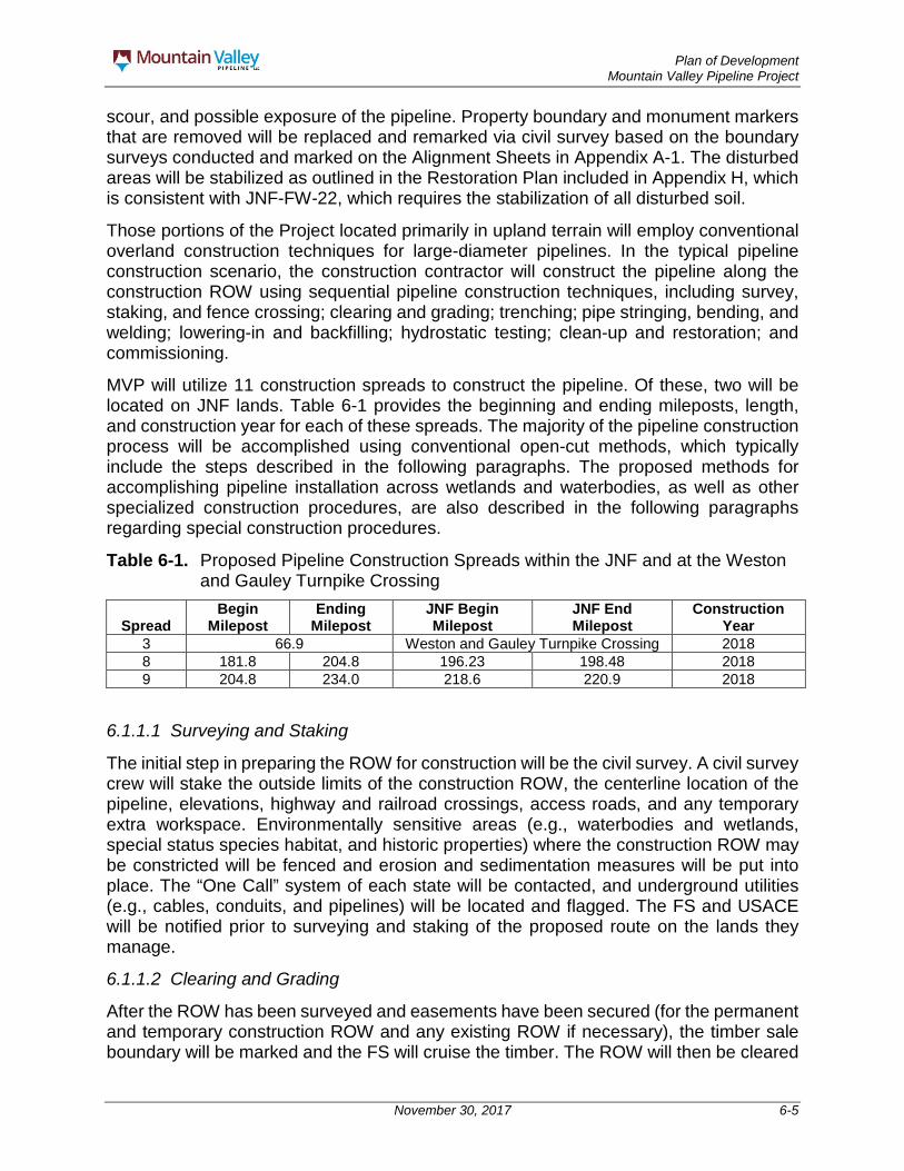
MVP will utilize 11 construction spreads to construct the pipeline. Of these, two will be located on JNF lands. Table 6-1 provides the beginning and ending mileposts, length, and construction year for each of these spreads. The majority of the pipeline construction process will be accomplished using conventional open-cut methods, which typically include the steps described in the following paragraphs. The proposed methods for accomplishing pipeline installation across wetlands and waterbodies, as well as other specialized construction procedures, are also described in the following paragraphs regarding special construction procedures.
Table 6-1. Proposed Pipeline Construction Spreads within the JNF and at the Weston and Gauley Turnpike Crossing
Spread Begin
Milepost Ending
Milepost JNF Begin Milepost
JNF End Milepost
Construction Year
3 66.9 Weston and Gauley Turnpike Crossing 2018 8 181.8 204.8 196.23 198.48 2018 9 204.8 234.0 218.6 220.9 2018
6.1.1.1 Surveying and Staking
The initial step in preparing the ROW for construction will be the civil survey. A civil survey crew will stake the outside limits of the construction ROW, the centerline location of the pipeline, elevations, highway and railroad crossings, access roads, and any temporary extra workspace. Environmentally sensitive areas (e.g., waterbodies and wetlands, special status species habitat, and historic properties) where the construction ROW may be constricted will be fenced and erosion and sedimentation measures will be put into place. The “One Call” system of each state will be contacted, and underground utilities (e.g., cables, conduits, and pipelines) will be located and flagged. The FS and USACE will be notified prior to surveying and staking of the proposed route on the lands they manage.
6.1.1.2 Clearing and Grading
After the ROW has been surveyed and easements have been secured (for the permanent and temporary construction ROW and any existing ROW if necessary), the timber sale boundary will be marked and the FS will cruise the timber. The ROW will then be cleared

Plan of Development Mountain Valley Pipeline Project
November 30, 2017 6-6
of obstructions (i.e., trees and stumps, brush, logs, and large rocks) according to the FERC Plan, as outlined in MVP’s Project-specific E&SCP, in the Timber Removal Plan (Appendix I), and as directed in the timber sale contract. The ROW will be cleared to the width required for construction, but not more than specified on the pipeline alignment sheets and marked with paint in the field. These ROW widths indicate the maximum width necessary for construction, operation, and maintenance of the pipeline. At no time will MVP or its contractor clear or alter any areas outside of the boundaries of the pipeline ROW area, including ATWS areas, shown on the pipeline alignment sheets.
Merchantable timber will be cut into lengths and stacked as described in the Timber Removal Plan in Appendix I on the edge of the ROW. Non-merchantable brush and slash will be retained on site to provide a level of erosion control until actual pipeline construction begins, at which time it will be windrowed to the edge of the right-of-way. Windrowing of non-merchantable brush and slash along the right-of-way will result in habitat for many types of wildlife including: rabbits and other small mammals, ruffed grouse, song birds and reptiles and provide food for insects. The windrows can also serve as escape cover from predators as well as locations for nesting and shelter from inclement weather. The windrows should be restricted to 8 feet tall, 20 feet wide, and 100 feet long with a 50-foot break between piles in order to provide fire breaks and wildlife crossings. Non-merchantable brush and slash can be utilized in downslope areas of the right-of-way and access roads to aide in soil stabilization and erosion control. Layering the brush and slash at the toe of a low-side slope along an access road provides soil stabilization, and erosion and sediment control. Layering of brush and slash can promote physical protection to the downslope areas of the right-of-way. Additionally, the layering can provide long-term support for revegetation in downslope areas of the right-of-way. Any remaining non-merchantable timber that cannot be windrowed will be chipped into trucks and removed from the site.
MVP will comply with the environmental protection measures and timing restrictions in the Migratory Bird Conservation Plan (Appendix V).
If fences (barbed wire, chain link, or other) occur along the construction ROW, then a fence crew will install temporary gates. The contractor’s fence crew will install new posts to brace the areas on either side of the proposed cut to ensure that no damage occurs to other portions of the fence or wall. Temporary gates will be installed, if necessary, to prohibit or otherwise control public access across the ROW. These temporary fences and/or gates will remain closed at all times except as required for construction purposes. Following construction, all original gates and fences will be repaired or replaced as necessary.
Where needed for erosion control, and in accordance with JNF-FW-6, the FERC Plan, Project E&SCP, and the Restoration Plan included as Appendix H will be implemented along the construction ROW. Best management practices (BMPs), found in the Erosion and Sediment control plans in Appendix C, will be properly maintained throughout construction and will remain in place until permanent erosion controls are installed and restoration is completed.

Plan of Development Mountain Valley Pipeline Project
November 30, 2017 6-7
6.1.1.3 Trenching
To bury the pipeline underground, it will be necessary to excavate a trench. The trench will be excavated with a track-mounted backhoe or similar equipment. Explosives will only be used when necessary in areas where rock substrates are found at depths that interfere with conventional excavation or rock-trenching methods. A General Blasting Plan is included as Appendix J. Blasting is also further discussed in Section 6.1.2.1 below. Soils removed during trenching will be stockpiled in accordance with FS’s requirement to segregate topsoil along the entire length of the ROW throughout the JNF.
Generally, the trench will be excavated at least 12 inches wider than the diameter of the pipe. The sides of the trench will be sloped with the top of the trench up to 12 feet across, or more, depending upon the stability of the native soils. The trench will be excavated to a sufficient depth to allow a minimum of three feet of soil cover between the top of the pipe and the final land surface after backfilling (minimum of 24 inches of cover will be provided in consolidated rock or in ditches). Wildlife fences will be used in coordination with escape ramps approximately every 50 feet as a deterrent on the edges of both sides of the ROW. Mountain Valley environmental inspectors will check the trench each morning prior to the start of work to ensure that any animals that are trapped in the trench are removed.
MVP will also follow the eagle guidelines set out in the USFWS Bald Eagle Management Guidelines and the Migratory Bird Conservation Plan, such as not conduct any clearing or construction activities within 660 feet of active eagle nests, and avoid blasting or use of explosives within 0.5 mile of active nests or communal concentration areas. Any biologists utilized to inspect for Eagle nest on the JNF will be approve by the FS.
Excavated soils will typically be stockpiled along the ROW on the side of the trench (the “spoil” side) away from the construction traffic and pipe assembly area (the “working” side). Where the route is co-located with Mystery Ridge Road, the spoil generally will be placed on the same side of the trench as the existing infrastructure. Following the backfilling of a trench, MVP will complete final grading, topsoil replacement, and mulch the disturbed areas within seven days as directed by the revegetation discussed in the Erosion and Sediment Control Plans (Appendices C-1 and C-2) and the restoration plan in Appendix H.
6.1.1.4 Pipe Assembly
Steel pipe for the pipeline will be procured in nominal double random and/or triple random lengths, or “joints,” protected with an epoxy coating applied at the factory or at a coating yard (the beveled ends will be left uncoated for welding) and shipped to strategically located materials storage areas, or “pipe yards.” The individual joints will be transported to the ROW by truck and placed along the excavated trench in a single, continuous line, easily accessible to the construction personnel on the working side of the trench, typically opposite the spoil side. This will allow the subsequent lineup and welding operations to proceed efficiently. At stream crossings, the amount of pipe required to span the stream will be stockpiled in the workspace on one or both banks of the stream.

Plan of Development Mountain Valley Pipeline Project
November 30, 2017 6-8
The pipe will be delivered to the job site in straight joints. The use of field controlled internal diameter fittings, in addition to the bending of pipe, will be required to allow the pipeline to follow natural grade changes and directional changes of the ROW. Prior to welding, selected joints will be bent in the field by track-mounted hydraulic bending machines.
Following stringing and bending, the joints of pipe will be placed on temporary supports, adjacent to the trench. The ends will be carefully aligned and welded together using multiple passes for a full penetration weld. Only qualified welders will be allowed to perform the welding. Automated welding techniques may be used in flatter areas if the terrain is suitable. Welders and welding procedures will be qualified according to applicable American Society for Mechanical Engineers, American Petroleum Institute (API), and 49 CFR Part 192 Standards.
To ensure that the assembled pipe will meet or exceed the design strength requirements, the completed welds will be visually inspected and tested for integrity using non-destructive examination methods, such as radiography (X-ray) or ultrasound, in accordance with API standards. Welds displaying unacceptable slag inclusions, void spaces, or other defects will be repaired or cut out and re-welded.
Following welding, the previously uncoated ends of the pipe at the joints will be sandblasted to a near-white finish and epoxy coated. The coating on the completed pipe section will be inspected, and damaged areas will be repaired. Coating will be inspected prior to lowering in accordance with applicable industry standards. Defects discovered in the coating will be repaired prior to lowering.
The completed section of pipe will be lifted off temporary supports and lowered into the trench by side-boom tractors or equivalent equipment. Prior to lowering the pipe, the trench will be inspected to ensure that it is free of rocks and other debris that could damage the pipe or the coating. Before the pipe is lowered into the trench, the pipe and trench will be inspected to ensure that the pipe and trench configurations are compatible. In rocky areas, if the bottom is not smooth, a layer of soil or sand may be placed on the bottom of the trench to protect the pipe using a padding machine or excavator with a “shaker bucket,” which separates rocks from satisfactory padding materials. Concrete-coated pipe or aggregate filled sacks will be used if required for negative buoyancy in areas of saturated soils.
After the pipe is lowered into the trench, the trench will be backfilled. Previously excavated materials will be pushed back into the trench using equipment or backhoes. Where the previously excavated material contains large rocks or other materials that could damage the pipe or coating, clean fill will be used to protect the pipe. Limestone dust or sand, which is typically basic and will often aid in the cathodic protection of the pipeline, may be used as backfill material. The first 12 inches above the top of the pipe will be clean fill free of rocks from the excavation. The remaining fill of the trench will be the aggregate of the excavation material removed at the time of the excavation. MVP does not anticipate there being a need for imported backfill material in the JNF. However, if fill is necessary, it will be sand or limestone dust provided by local vendors as approved by MVP and the FS. Prior to replacing topsoil, excess soil will be distributed evenly on the ROW, only in upland areas, while maintaining existing contours. As noted above, topsoil will be segregated
Plan of Development Mountain Valley Pipeline Project
November 30, 2017 6-9
along the entire length of the ROW within the JNF and will be placed after backfilling the trench above the subsoil. Compaction during the backfilling process will be achieved by using excavators and bulldozers to track in the material. Following backfilling in agricultural land, grassland, and open land, a small crown may be left to account for any future soil settling that might occur. In wetlands, a crown will not be left in order to restore hydrology to pre-existing conditions.
6.1.1.5 Hydrostatic Test and Final Tie-In
Following backfilling of the trench, the pipeline will be hydrostatically tested to ensure that it is capable of safely operating at the design pressure. Baseline water samples will be taken at the source prior to water-up and prior to discharge. Test segments of the pipeline will be capped with test manifolds and filled with water and pressurized to a minimum of 1.1 to 1.25 times (based on location class) the designed operating pressure for a minimum of eight hours in accordance with USDOT requirements identified in 49 CFR Part 192 prior to being placed in service. Loss of pressure that cannot be attributed to other factors, such as temperature changes, will be investigated. Leaks detected will be repaired, and the segment will be retested.
Upon completion of the test, the water may be pumped to the next segment for testing. Test water will contact only new pipe. If chlorinated water is used for testing, a de-chlorinating agent will be required prior to discharge.
Once a segment of pipe has been successfully tested and dried, the test manifold will be removed, and the pipe will be connected to the remainder of the pipeline. Desiccant will not be used to dry the pipe. MVP will implement Section VII of the FERC Procedures (Appendix H) regarding hydrostatic testing, as well as any specifications in individual state permit guidelines. No water from resources within the JNF will be used for hydrostatic testing, and no waters used during hydrostatic testing will be discharged on FS or USACE managed lands. Water used for hydrostatic tests that occur on the JNF will be obtained from municipal sources.
6.1.1.6 Cleanup and Restoration
Post-construction restoration activities will be undertaken in accordance with the measures specified in the Restoration Plan (Appendix H). After a segment of pipe has been installed, backfilled, and successfully tested, the ROW, ATWS, and other disturbed areas will be finish-graded, and the construction debris will be disposed of properly. The surface of the ROW disturbed by construction activities will be graded to match original contours and to be compatible with surrounding drainage patterns, except at those locations where permanent changes in drainage will be required to prevent erosion, scour, and possible exposure of the pipeline. Temporary and permanent erosion and sediment control measures, including silt fencing, diversion terraces, and vegetation, will be installed at that time. Fences, gates, driveways, and roads that have been disturbed by the pipeline construction will be restored to original or better condition. More information on restoration is provided in Section 8.
During construction, Mountain Valley will gather and dispose of trash created as a result of Project construction or by Mountain Valley employees and contractors each day.

Plan of Development Mountain Valley Pipeline Project
November 30, 2017 6-10
6.1.1.7 Construction in Rugged Terrain
In mountainous areas where the pipeline will encounter slopes that typically exceed 30 degrees, MVP will employ special construction techniques. Appendix B includes figures that detail average slopes within the JNF. The elevation data were found using 3-meter digital elevation model files generated from flown LiDAR. Average slopes were calculated for each 0.1-mile interval along the pipeline centerline, and every 0.25-mile interval along the access road. In each 0.1-mile interval, the steepest data point was taken as the maximum slope.
ATWS located outside the 125-foot construction ROW for the pipeline on JNF may be utilized for staging equipment necessary for special construction techniques. Approximately one acre of ATWS will be utilized within the JNF for construction in rugged terrain, located along the pipeline alignment.
In rugged terrain, temporary sediment barriers, such as silt sock and reinforced silt fences, will be installed during clearing to prevent movement of sediment off the ROW. In addition, temporary slope breakers will be installed during grading in accordance with the E&SCP to reduce water runoff or divert water to vegetated areas. Spoil piles adjacent to the trench will be protected by temporary sediment barriers to keep excavated soils on the ROW.
Construction activities on rugged terrain will be similar to the typical construction; however, equipment will be tethered via winch lines to other equipment at the top of the slopes to ensure the safety of the construction personnel and surrounding areas. Equipment used for the construction activity will be suspended from a series of winch tractors to maintain control of the equipment and provide an additional level of safety (Figure 6-2). All construction equipment and their winch lines will be inspected prior to operation to ensure the equipment is operable and sound.
Pipe joints will be stockpiled at the top or bottom of each slope. A side-boom tractor will be suspended from a winch that will carry one joint at a time up or down the slope and place the joint along the trenchline. The joint will then be lowered into the ditch by a tractor. Welders will connect the joint to the previous joint within the trench to assemble the pipeline. Once welding is complete, the welds will be visually and radiographically inspected. The weld joints will be hand coated with fusion-bonded epoxy coatings in accordance with required specifications. The coating on the pipe and at the weld will be inspected for defects and repaired, if necessary. Sand trench breakers will be installed in the trench along the pipeline to prevent or slow the movement of water along the trench. The pipeline will be padded and the trench will be backfilled by equipment tethered to the winch tractors. The surface of the ROW will be restored to original contours to the extent practical, and permanent slope breakers will be installed in accordance with the E&SCP. Erosion control blankets or hydroseed, in lieu of mulch, will be installed on steep slopes to provide stabilization for vegetation to help control sediment and water runoff. In areas where the Project route crosses laterally across the face of a slope (side-hill construction), cut-and-fill grading may be required to establish a safe, flat work terrace which will be reclaimed as close as practical to original contours.

Plan of Development Mountain Valley Pipeline Project
November 30, 2017 6-11
Figure 6-2. Stove-Pipe Construction

Plan of Development Mountain Valley Pipeline Project
November 30, 2017 6-12
MVP will incorporate erosion and sediment control measures such as super silt fence, silt fence, sock filtration, erosion control socks, temporary and permanent water bars, ditch breakers, temporary mulch, and erosion control blankets as per Project design specifications based on slope as described in the Erosion and Sediment Control Plans (Appendix C, the Landslide Mitigation Plan (Appendix F), and the JNF Priority Site Plan (Appendix G).
On steep slopes, various measures will be taken in order to properly control erosion and sedimentation on the ROW. Spoil piles from trenching operations will be staged along the side of the ROW and will be compacted via rolling with dozers on site as additional material is added. Once a spoil pile is completed, it will be temporarily mulched to control washouts. Additionally, spoil piles will be separated at intervals of 50 feet by temporary water bars, which will serve to slow the flow of runoff down the ROW and divert it into No. 3 aggregate. Measures such as erosion control blankets and sock filtration may be used to stop rocks from rolling off of the ROW.
Within the trench, sand-filled sacks will be stacked across the width of the trench as necessary based on field conditions. This will permit water to slowly filter through without carrying large amounts of soil with it. Similarly, permeable trench breakers constructed of sand- or aggregate-filled sacks will be installed along the open ditch. Rock-fall protection measures such as rock fences, placement of concrete barriers, or creating catchment areas may be added where excavation is planned subjacent to steep slopes, as determined by the contractor. Once the area is stabilized, following construction, MVP will remove any temporary stabilization methods. Contours will be returned to pre-existing conditions to the extent practicable.
In addition to the measures taken on slopes to control erosion and sedimentation, trench drains will be installed on side slopes and steep slopes before the pipe is placed in order to channel water away from the ditch, and these drains will not be removed after construction is complete. These permanent drains will consist of perforated tile or pipe surrounded with rock (1-inch stone or similar, which may be taken from excavated spoils) that will terminate at a riprap pad near the edge of the ROW. Geotechnical inspectors will evaluate the need for additional engineering controls based on the subsurface conditions exposed in the pipeline excavation; such engineering controls could include regrading adjacent areas, embedding the pipeline in a bedrock trench, installing drains, buttressing unstable slopes, reinforcing fill slopes with geosynthetics, or other stabilization measures as appropriate.
On side-hill construction, tree stumps and other organic material will be removed from backfill material along the ROW, as decomposing organic materials and organic soils tend to exhibit low shear strengths and may accumulate water, increasing the likelihood of a landslide. Special attention will be paid to ensure that natural drains alongside slopes are properly restored after construction activities are complete. In order to accomplish this, additional French drains or rock-lined channels may be constructed to efficiently convey water across or around the ROW. Where seeps and springs are observed in the cut slope, cutoff drains and/or transverse trench drains will be installed to prevent saturation of the backfilled material. Where possible, compaction on side-cut sections should be completed in 12-inch lifts using a sheep’s foot roller.
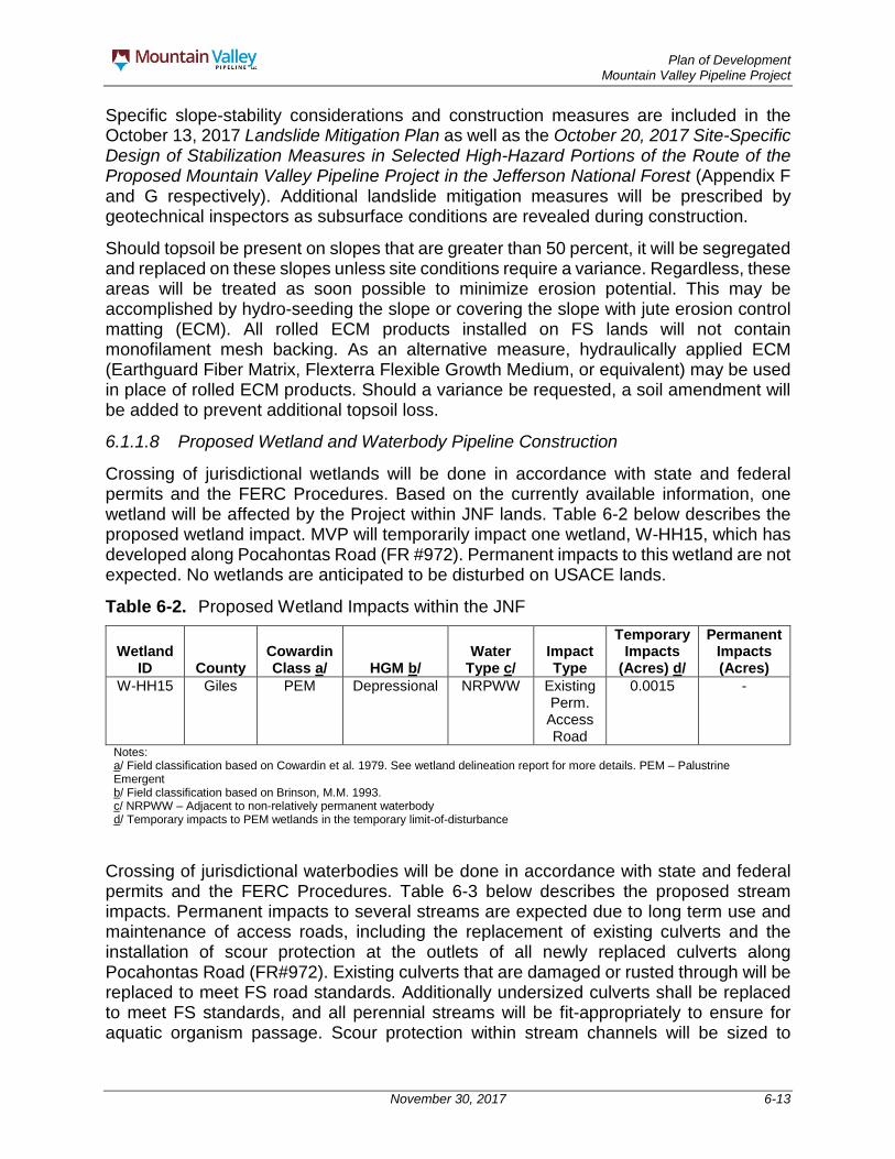
Plan of Development Mountain Valley Pipeline Project
November 30, 2017 6-13
Specific slope-stability considerations and construction measures are included in the October 13, 2017 Landslide Mitigation Plan as well as the October 20, 2017 Site-Specific Design of Stabilization Measures in Selected High-Hazard Portions of the Route of the Proposed Mountain Valley Pipeline Project in the Jefferson National Forest (Appendix F and G respectively). Additional landslide mitigation measures will be prescribed by geotechnical inspectors as subsurface conditions are revealed during construction.
Should topsoil be present on slopes that are greater than 50 percent, it will be segregated and replaced on these slopes unless site conditions require a variance. Regardless, these areas will be treated as soon possible to minimize erosion potential. This may be accomplished by hydro-seeding the slope or covering the slope with jute erosion control matting (ECM). All rolled ECM products installed on FS lands will not contain monofilament mesh backing. As an alternative measure, hydraulically applied ECM (Earthguard Fiber Matrix, Flexterra Flexible Growth Medium, or equivalent) may be used in place of rolled ECM products. Should a variance be requested, a soil amendment will be added to prevent additional topsoil loss.
6.1.1.8 Proposed Wetland and Waterbody Pipeline Construction
Crossing of jurisdictional wetlands will be done in accordance with state and federal permits and the FERC Procedures. Based on the currently available information, one wetland will be affected by the Project within JNF lands. Table 6-2 below describes the proposed wetland impact. MVP will temporarily impact one wetland, W-HH15, which has developed along Pocahontas Road (FR #972). Permanent impacts to this wetland are not expected. No wetlands are anticipated to be disturbed on USACE lands.
Table 6-2. Proposed Wetland Impacts within the JNF
Wetland ID County
Cowardin Class a/ HGM b/
Water Type c/
Impact Type
Temporary Impacts
(Acres) d/
Permanent Impacts (Acres)
W-HH15 Giles PEM Depressional NRPWW Existing Perm. Access Road
0.0015 -
Notes: a/ Field classification based on Cowardin et al. 1979. See wetland delineation report for more details. PEM – Palustrine Emergent b/ Field classification based on Brinson, M.M. 1993. c/ NRPWW – Adjacent to non-relatively permanent waterbody d/ Temporary impacts to PEM wetlands in the temporary limit-of-disturbance
Crossing of jurisdictional waterbodies will be done in accordance with state and federal permits and the FERC Procedures. Table 6-3 below describes the proposed stream impacts. Permanent impacts to several streams are expected due to long term use and maintenance of access roads, including the replacement of existing culverts and the installation of scour protection at the outlets of all newly replaced culverts along Pocahontas Road (FR#972). Existing culverts that are damaged or rusted through will be replaced to meet FS road standards. Additionally undersized culverts shall be replaced to meet FS standards, and all perennial streams will be fit-appropriately to ensure for aquatic organism passage. Scour protection within stream channels will be sized to
Plan of Development Mountain Valley Pipeline Project
November 30, 2017 6-14
withstand the tailwater velocity and shear corresponding to the 25-year design flow event. No streams are anticipated to be disturbed on USACE lands.
Construction across waterbodies will be performed to minimize the time that the trenches for the pipeline crossings of flowing streams and rivers will be left open. The normal trenching operation will skip the waterbody crossing, stopping on each side near the top of bank. The waterbody section of the pipeline will be installed by one of the methods described below. In general, pipe will be bent and fabricated as the work progresses along the ROW so that the excavation of the waterbody crossing is only completed immediately prior to pipe installation by the tie-in crew.
Plan of Development, Restoration Plan, & Erosion and Sediment Details specific to the JNF are included in Appendix K.
Intermediate waterbodies (between 10 and 100 feet wide at water’s edge) and minor waterbodies (less than 10 feet wide at water’s edge) will be crossed by the dry open-cut/conventional crossing methods (either dam and pump around or flume), unless otherwise required. Pipe will be installed to provide a minimum of four feet of cover from the waterbody bottom to the top of the pipeline, except in consolidated rock, where a minimum of two feet of cover will be required. Waterbody crossings consisting of consolidated rock will be backfilled with active material and will require a minimum two-foot depth of cover. If scour is a concern, an armoring layer with a given minimum stone size would restrict potential scour. The backfill will then consist of riprap stone equal to or greater than the minimum armor particle size. Pipeline burial depth would be determined after the size of the armoring layer is finalized. Trench spoil will be placed on the bank above the high water mark for use as backfill.
A prefabricated segment of pipeline will be laid horizontally across the waterbody bed and continue 10 feet past the high banks on each side of the waterbody before raising in elevation to the normal trench level.
Normal backfill cover requirements will be met. Compaction percentage of backfill will be equal to or above that of the adjacent undisturbed areas. Ditch plugs of crushed stone, sandbags, or dry soil may also be used to keep backfill from sloughing in toward the center of the waterbody. All waterbody banks will be restored to their original grades, and foreign objects will be removed from the waterbody. Excavated material not required for backfill will be removed and disposed of at an upland site.
MVP will follow state and federal permits and FERC Procedures to limit water quality and aquatic resource impacts during and following construction. Construction activities will be scheduled so that the pipeline trench is excavated immediately prior to pipe laying activities. In accordance with FERC’s Procedures, the duration of construction will be limited to 24 hours across minor waterbodies (10 feet wide or less) and 48 hours across intermediate waterbodies (between 10 and 100 feet wide) when blasting or extensive rock excavation is not required.

Plan of Development Mountain Valley Pipeline Project
November 30, 2017 6-15
Table 6-3. Proposed Waterbody Impacts within the JNF
Stream ID
NHD Stream Name a/ County
FS Flow Regime b/
Water Type c/ Impact Type
Top of Bank Width
(ft)
Temp. Linear Feet
Impact (ft)
Perm. Linear Feet
Impact (ft)
Designation d/
Water Quality
e/
S-PP14 Kimballton Branch Giles Perennial RPW Perm.
Access Road 14 50 11 - 3A
S-PP15 UNT to Kimballton Branch
Giles Perennial RPW Perm. Access Road 6 15 11 - 3A
S-PP17 UNT to New River Giles Perennial RPW Perm.
Access Road 2 - 14 - 3A
S-PP18 Curve Branch Giles Perennial RPW Perm. Access Road 4 - 19 - 3B
S-PP19 UNT to Curve Branch Giles Perennial RPW Perm.
Access Road 3 - 16 - 3A
S-UU9 Clendennin Creek Giles Perennial RPW Perm.
Access Road 5 - 11 - 3A
S-HH16 UNT to Clendennin Creek
Giles Perennial RPW Perm. Access Road 5 55 - - 3A
S-MN17 UNT to Clendennin Creek
Giles Intermittent RPW Perm. Access Road 3 42 - - 3A
S-MN20 UNT to Clendennin Creek
Giles Intermittent RPW Perm. Access Road 4 - 11 - N/A
S-HH15 UNT to Clendennin Creek
Giles Perennial RPW Perm. Access Road 5 - 14 - N/A
S-HH14 UNT to Clendennin Creek
Giles Perennial RPW Perm. Access Road 3 - 14 - N/A
S-HH12 UNT to Clendennin Creek
Giles Ephemeral NRPW Perm. Access Road 3 - 11 - N/A

Plan of Development Mountain Valley Pipeline Project
November 30, 2017 6-16
Stream ID
NHD Stream Name a/ County
FS Flow Regime b/
Water Type c/ Impact Type
Top of Bank Width
(ft)
Temp. Linear Feet
Impact (ft)
Perm. Linear Feet
Impact (ft)
Designation d/
Water Quality
e/
S-PP22 UNT to Craig Creek Montgomery Intermittent RPW Pipeline
ROW 2.5 83 - - N/A
S-PP21 UNT to Craig Creek Montgomery Perennial RPW Pipeline
ROW 4 97 - - N/A
S-PP20 UNT to Craig Creek Montgomery Perennial RPW Pipeline
ROW 6 89 - - 3A
S-HH18 UNT to Craig Creek Montgomery Perennial RPW Pipeline
ROW 6 78 - - 3A
Notes: a/ For identified streams without a NHD name, the identified stream was given the name, “Unnamed Tributary (UNT)”, of the first named receiving waterbody. b/ FS flow regime is based on FS land management procedures and may differ from USACE flow regime c/ RPW = Relatively Permanent Waters; NRPW = Non-Relatively Permanent Waters d/ Trout Waters - Cold Water Streams Survey (CWSS) - trout streams as determined by Virginia Department of Game and Inland Fish available at:
https://www.dgif.virginia.gov/gis/data/download/; Anadromous Fish Use Areas - as determined by Virginia Department of Game and Inland Fish available at:
https://www.dgif.virginia.gov/gis/data/download/; Tier 3 - Exceptional State Waters (Tier III) list available at:
http://www.deq.virginia.gov/Programs/Water/WaterQualityInformationTMDLs/WaterQualityStandards/ExceptionalStateWaters(TierIII).aspx e/ Water Quality/Quantity data are taken from existing sources including: EPA Storet (https://www.epa.gov/waterdata/storage-and-retrieval-and-water-quality-exchange) and VA DEQ Final 2014 305(b)/303(d) Water Quality Assessment Integrated Report available at - http://www.deq.virginia.gov/Programs/Water/WaterQualityInformationTMDLs/WaterQualityAssessments/2014305(b)303(d)IntegratedReport.aspx - 3A - Category 3A (Indeterminate - Waters needing additional information, water was not previously listed as impaired) from VA DEQ Final 2014 305(b)/303(d) Water
Quality Assessment Integrated Report - 3B - Category 3B (Indeterminate - Waters needing additional information, waters will be prioritized for follow-up monitoring as resources allow) from VA DEQ Final 2014
305(b)/303(d) Water Quality Assessment Integrated Report -N/A - Publically available water quality/quantity data was not available from the sources listed above
F

Plan of Development Mountain Valley Pipeline Project
November 30, 2017 6-17
Crossings of minor perennial and intermittent streams will be accomplished in accordance with state and federal permits and the FERC Procedures. Dry-ditch waterbody crossing methods include dam and pump or flume. Where a dry-ditch crossing method is not specifically required by FERC’s Procedures, the waterbody may be crossed using the open-cut crossing method. The crossing method is subject to change depending upon the actual conditions encountered at the time of construction. Crossing methods are described below. There are no waterbodies that would be affected by the pipeline crossing at the Weston and Gauley Turnpike.
Dam-and-Pump Crossing Method The dam-and-pump method involves installation of temporary dams upstream and downstream of the proposed waterbody crossing. The temporary dams will typically be constructed using sandbags and plastic sheeting. Following dam installation, appropriately sized pumps will be used to dewater and transport the stream flow around the construction work area and trench. Intake screens will be installed at the pump inlets to prevent entrainment of aquatic life, and energy-dissipating devices will be installed at the pump discharge point to minimize erosion and stream bed scour. Trench excavation and pipeline installation will then commence through the dewatered portion of the waterbody channel. Following completion of pipeline installation, backfill of the trench, and restoration of stream banks, the temporary dams will be removed, and flow through the construction work area will be restored. This method is generally only appropriate for those waterbody crossings where pumps can adequately transfer the stream flow volume around the work area and there are no concerns about the passage of sensitive species.
Flume Crossing Method The flume crossing method will consist of temporarily directing the flow of water through one or more flume pipes placed over the area to be excavated. This method will allow excavation of the pipe trench across the waterbody completely underneath the flume pipes without disruption of water flow in the stream. Stream flow will be diverted through the flumes by constructing two bulkheads and using sand bags or plastic dams to direct the stream flow through the flume pipes. Following completion of pipeline installation, backfill of the trench, and restoration of stream banks, the bulkheads and flume pipes will be removed. This crossing method generally minimizes the duration of downstream turbidity by allowing excavation of the pipeline trench under relatively dry conditions.
Following construction, MVP will monitor and record the success of revegetation on FS-managed lands for up to five growing seasons or until the area is 80 percent revegetated. Inspection will be completed as least annually. MVP will submit a status report to the FS following each inspection. Should a stream bank’s vegetation not reestablish following five growing seasons, MVP will work with FS personnel to develop a plan for re-establishment, including monitoring requirements.
6.1.1.9 Typical Road Crossings
During construction on FS Property, motorized access will be maintained along Pocahontas (FR #972), Mystery Ridge (FR #11080), and Brush Mountain (FR #188) Roads at all times to FS personnel, other personnel authorized by the FS, and emergency response officials. The pipeline will be parallel to Mystery Ridge Road and cross the road

Plan of Development Mountain Valley Pipeline Project
November 30, 2017 6-18
one time. Mountain Valley will also cross Brush Mountain Road. While Mountain Valley open cuts and crosses Mystery Ridge and Brush Mountain Roads, the roads will be closed to all through traffic for approximately five days. Should access for the FS or emergency purposes be necessary during those five days, the disturbed area will be covered with a steel plate. Following construction each day, the open trench across Brush Mountain Road (FR #188) will be covered over with a steel plate to allow for passage as necessary. At points of access to the ROW from hard-surfaced roads, a stone pad will be installed as a construction entrance to control mud and dirt tracking onto the highway. Most of the smaller unpaved roads and drives will be crossed by open trenching and then restored to pre-construction conditions or better. If an open-cut road requires extensive construction time, provisions will be made for temporary detours or other measures to allow safe traffic flow during construction. The pipeline will be buried to a depth of at least three feet below the road surface and will be designed to withstand anticipated external loadings such as logging trucks and other heavy equipment. Following construction each day, any open trench will be covered over with a steel plate to allow for passage as necessary.
6.1.1.10 Trail Crossings
The Weston and Gauley Turnpike and the ANST will be crossed using a conventional bore crossing method. For the crossing of the ANST and Weston and Gauley Turnpike, if the first attempt to cross by conventional bore is unsuccessful, an offset will be made to the bore and a second attempt will be made with a conventional bore within the approved temporary construction ROW. In the unlikely situation that two conventional bores are not successful, additional attempts to cross the Weston and Gauley Turnpike by conventional bore within the approved construction ROW will be made. Should a failure occur during the bore of the ANST, the Conventional Bore Contingency Plan (Appendix E) would be utilized per approval from FERC and FS.
To complete a conventional bore, two pits will be excavated, one on each side of the feature to be bored. A boring machine will be lowered into one pit, and a horizontal hole will be bored to a diameter equal to the diameter of the pipe at the depth of the pipeline installation. The pipeline section will then be pushed through the bore to the opposite pit. If additional pipeline sections are required to span the length of the bore, they will be welded to the first section of the pipeline in the bore pit before being pushed through the bore.
6.1.1.11 Typical Topsoil Segregation
MVP will segregate topsoil along the entire length of the ROW throughout the JNF. Should topsoil be present on slopes that are greater than 50 percent, it will be segregated and replaced on these slopes unless site conditions require a variance. Regardless, these areas will be treated as soon possible to minimize erosion potential. This may be accomplished by hydro-seeding the slope or covering the slope with jute ECM. All rolled ECM products installed on FS lands will not contain monofilament mesh backing. As an alternative measure, hydraulically applied ECM (Earthguard Fiber Matrix, Flexterra Flexible Growth Medium, or equivalent) may be used in place of rolled ECM products. Should a variance be requested, a soil amendment will be added to prevent additional topsoil and organic matter loss.

Plan of Development Mountain Valley Pipeline Project
November 30, 2017 6-19
6.1.2 Special Construction Procedures
6.1.2.1 Blasting
MVP will minimize the amount of blasting required to the extent practicable. Where unrippable subsurface rock is encountered, blasting for ditch excavation and the conventional bore pit on the southeast slope of Peters Mountain may be necessary. Where competent sandstone bedrock occurs in the stream bed, blasting may be used to reduce bedrock so that the trench can be excavated. However, MVP has extensive experience with pipeline installation in the Dunkard, Monongahela, and Conemaugh formations (Permian to Pennsylvanian Age clastic sedimentary bedrock) found in the Appalachian Plateau geologic province of northern West Virginia (e.g., Wetzel County). These geologic formations consist of cyclic sequences of shale, siltstone, sandstone, thin limestone beds, nonpersistent coal, and other accessory rock types. These formations are similar in nature to the Ordovician to Mississippian clastic formations found in the Valley and Ridge geologic province of southwestern Virginia. MVP routinely rips these clastic sedimentary formations without the need for blasting. This suggests that mechanical ripping should be sufficient for bedrock trenching on NFS property without the use of blasting. However, Table 6-4 below lists areas within the JNF where blasting may be necessary.
Table 6-4. Bedrock Rippability and Possible Extent of Blasting on JNF
Between Mile Posts Discussion Rippability Assessment
Likely to require
blasting? 196.35 - Enter NFS property n/a n/a 196.35 196.4 Peters Mountain ridgeline. Steeply
dipping (southeast) thin-to-medium bedded sandstones outcrops, highly jointed.
Rippable due to outcrop orientation and jointing.
Possible
196.4 196.45 Bore pit Bore pit staging will require more rock excavation than trenching. May encounter unweathered hard rock that requires blasting to support excavation.
Possible
196.45 197.0 Alignment primarily underlain by unconsolidated colluvial and ancient debris flow deposits
Rippable due to unconsolidated deposits overlying the upper reaches of weathered bedrock.
No
197.0 197.8 Thin overburden mantle overlying highly jointed sandstone bedrock.
Rippable due to outcrop orientation and jointing.
No
197.8 198.2 Leave NFS property n/a n/a 198.2 198.35 Re-enter NFS property. Underlain
by unconsolidated colluvial and ancient debris flow deposits
Rippable due to unconsolidated deposits overlying the upper reaches of weathered bedrock.
No
198.35 218.53 Leave NFS property n/a n/a 218.53 218.65 Re-enter NFS property. Sinking
Creek Mountain ridgeline. Steeply dipping (southeast) thin-to-medium bedded sandstones outcrops, highly jointed.
Rippable due to outcrop orientation and jointing.
Possible

Plan of Development Mountain Valley Pipeline Project
November 30, 2017 6-20
218.65 218.8 Sandstone rock-block slump covered by overburden mantle.
Rippable due to unconsolidated deposits overlying the upper reaches of weathered bedrock.
Possible
218.8 219.35 Alignment underlain by unconsolidated colluvial and ancient debris flow deposits
Rippable due to unconsolidated deposits overlying the upper reaches of weathered bedrock.
No
219.35 219.7 Leave NFS property n/a n/a 219.7 220.72 Re-enter NFS property. Steeply
dipping, highly jointed Brallier formation fine sandstone, siltstone, shale observed at stream crossing near Mile Post 219.7.
Rippable due to outcrop orientation and jointing, and rock character.
No
219.72 220.7 Alignment ascends north slope of Brush Mountain crossing overburden mantle that overlying Brallier siliciclastic bedrock to the ridge line where Price Formation sandstone outcrops.
Rippable due to unconsolidated deposits overlying the upper reaches of weathered bedrock. Thin-to-medium-bedded ridge-forming sandstones are steeply dipping and highly jointed and considered rippable.
No
- 220.7 Leave NFS property n/a n/a
If blasting is required on the JNF, MVP is committed to taking measures to prevent damage to underground structures (e.g., cables, conduits, and pipelines) or to springs, water wells, or other water sources. Blasting mats or padding will be used as necessary to prevent the scattering of loose rock. All blasting will be conducted during daylight hours and will not begin until occupants of nearby buildings, stores, residences, places of business, and farms have been notified.
MVP will utilize blasting sirens, post warning signs near blasting zones, and post public announcements on FS-JNF existing information kiosks, any new information kiosks determined necessary by the FS, and the FS-JNF website (Alerts & Warnings), as permitted by the FS. MVP will also provide the blasting notices to the BLM and USACE to post on their public notification sites as appropriate. All blasting will be conducted in accordance with the General Blasting Plan (Appendix J), which includes providing notifications to the FS and BLM 24 hours prior to any blasting activities on federal lands. Pre- and post- blasting structural surveys will be conducted of occupied structures, water supply wells, and water supply springs that will be specified in the Blasting Plan. Avian survey teams will search for nests prior to blasting activities during nesting season (April 1 – August 31). If an active nest is located within the blasting area, a 100-foot buffer area will be marked, and blasting will not occur within the 100-foot buffer until the nest is no longer active. Most nesting habitat will have already been cleared prior to the need to blast.
6.1.2.2 Stove-Pipe Construction
On slopes steeper than 30 degrees (approximately 58 percent slope), the pipeline will be installed via a “stovepiping” method (see Figure 6-2). The stove-pipe method entails excavating a trench long enough to install two joints of pipe (approximately 40 feet long),lowering the pipe into the trench, and then welding the pipe in the trench. Following welding, inspection, and coating, the welded joint of pipe is backfilled before moving on
Plan of Development Mountain Valley Pipeline Project
November 30, 2017 6-21
to the next two joints of pipe. This process is performed for each successive joint of pipe up the slope. This construction technique will reduce the length of pipe that will be handled at any one time and minimize the amount of open trench on steep slopes. The general construction and restoration methods that will be applied during stove-pipe construction will be similar to those described above for rugged terrain.
6.1.2.3 Karst Area
The Mountain Valley Karst Specialist Team (KST), comprised of experts with decades of experience studying karst hydrogeology of Virginia and West Virginia, completed a Karst Hazards Assessment (KHA) (Resource Report #6; most recently updated February 2017) that included a desktop review of mapping from the United States Geological Survey, West Virginia Department of Environmental Protection, and Virginia Department of Mines, Minerals, and Energy and other sources. The KHA also included field verification in known karst areas underlying the proposed alignment and related construction components.
No karst terrain was observed in the vicinity of the Weston and Gauley Turnpike crossing.
The Geologic Map of Giles County, Virginia (Rader and Gathright; 1986) published by the Virginia Department of Mines, Minerals, and Energy, indicated the Silurian age Tonoloway Limestone and Keefer Sandstone (undivided) are present in the JNF where traversed by the proposed alignment. The Tonoloway Limestone is a laminated limestone with thin interbedded calcareous shale and siltstone. Being comprised of carbonate mineralogy, the Tonoloway Limestone has the potential for karst formation. However, literature review conducted for the KHA (referenced above) and field investigation conducted by the KST did not identify surficial karst features on JNF lands. Nonetheless, Mountain Valley will employ safeguards during construction in potential karst areas in the event that subsurface karst features are encountered.
The Mountain Valley Karst Mitigation Plan (KMP) (Resource Report #6; most recently updated February 2017) includes inspection and mitigation measures to be enacted if a subsurface karst feature is encountered during construction. As part of the KMP, the Mountain Valley KST will be on-site during all phases of construction in karst terrain to document the protection of known karst features, and to monitor for and mitigate if necessary newly observed karst features. The KMP is included herein as Attachment L.
6.1.2.4 Trench Dewatering
In most cases, trench dewatering will be limited to the removal of storm water and shallow ground water in the pipe trench excavated in upland locations. In saturated wetlands, it would not be practical to attempt to dewater the trench, since the groundwater level is at or near the ground surface. In those locations, the pipe may be concrete-coated or weighted with aggregate filled sacks to overcome buoyancy in the flooded trench.
In uplands, storm water will typically be removed from the trench prior to lowering the pipe into place. The storm water will be pumped from the trench to a location downgradient of the trench. The trench will be dewatered in a manner that does not cause erosion and does not result in silt-laden water flowing into any waterbody or wetland. The storm water will be discharged to an energy dissipation/filtration dewatering device, such as a straw bale structure. Heavily silt-laden water may first be passed through a filter bag. The

Plan of Development Mountain Valley Pipeline Project
November 30, 2017 6-22
dewatering structure will be removed as soon as possible after completion of the dewatering activities. Trench breakers (ditch plugs) will be used where necessary to separate the upland trench from adjacent wetlands or waterbodies to prevent the inadvertent draining of the wetland or diversion of water from the waterbody into the pipe trench.
6.1.2.5 Winter Construction
MVP has developed a Winter Construction Plan (Appendix M), which identifies BMPs for construction activities during snow accumulation. MVP will stop working in winter if weather conditions occur that are deemed unsafe to perform pipeline construction. Inspections will occur within 24 hours of each 0.5 inch of rainfall or snow melt. MVP will ensure the repair of all ineffective temporary erosion control measures within 24 hours of identification, or as soon as conditions allow if compliance with this time frame would result in the greater environmental impacts.
As necessary during snow accumulation, snow will be removed from construction work areas to expose soils for grading and excavation. Snow removal will be limited to active construction areas and areas needed to maintain access to the construction ROW. Snow will be bladed or pushed to the edges of the ROW with a motor-grader, snowplow, or bulldozer fitted with a “shoe” to minimize impacts on underlying soils and vegetation and stockpiled within the ROW. Snow will not be bladed off the ROW. Snow removal equipment will access the Project areas from approved access roads and will operate from within the construction ROW. When snow accumulation is more than one foot, it will be removed from the working and spoil sides of the construction ROW and the trench prior to topsoil segregation and grading to prevent mixing of snow with excavated spoil. If topsoil is saturated with water or frozen during excavation, it will not be segregated. Erosion and sediment control devices and diversion berms will be installed where needed to control snow and melting runoff.
Pickup trucks with front-mounted blades will plow access roads. Removed snow will not mix with sidecast stored soils. No additional temporary work space has been identified for snow storage.
6.2 Work Force Based on current discussions with qualified construction contractors, MVP estimates that local workers will account for approximately 25 percent of construction jobs for each spread for the duration of the Project. The remaining 75 percent of the construction workforce will consist of non-local workers. Local workers are defined here as those who normally reside within daily commuting distance of the work sites. The portion of the Project that crosses the JNF occurs along Spreads 8 and 9, which MVP anticipates will have an average employment level of 289 non-local workers and a 96 local workers, for a total average of 385 workers, and a peak employment of 536 non-local workers and 179 local workers, for a total of 715 workers, during construction for both Spreads.
The number of vehicles that will be used to move construction personnel to the Project site on the JNF is not known at this time. This will be determined by the construction

Plan of Development Mountain Valley Pipeline Project
November 30, 2017 6-23
contractor at the time of construction. The contractors will be encouraged to utilize buses and/or multi-passenger vehicles to limit the amount of traffic to a minimum.
6.3 Communication Procedures and Notification Protocols Timely, clear, and effective communication between Mountain Valley, FS, BLM, FERC, and contractors on-site is a critical component to the success of the Project. Communication protocols related to environmental inspection, compliance monitoring, reporting requirements, and Project variance requests are described further in Appendix N – Environmental Compliance Management Plan to this POD.
6.4 Roles and Responsibilities During construction, MVP will provide contractors with all Project design documents, including environmental alignment sheets, and copies of all applicable federal, state, and local permits. Construction will be supervised by a company Chief Inspector. MVP will file weekly status reports with FERC and the FS that address construction and restoration activities on the JNF and to the USACE when activity is occurring in the area of Burnsville Lake and the Weston and Gauley Turnpike. These weekly reports will be available to the public on the FERC eLibrary system.
MVP will fund a FERC third-party compliance monitoring program during Project construction phase. Under this program, a contractor is selected by, managed by, and reports solely to the FERC staff to provide environmental compliance monitoring services. The FERC Compliance Monitor will provide daily reports to FERC and the FS on compliance issues and make recommendations to the FERC Project Manager on how to deal with compliance issues and construction changes, should they arise. In addition to this program, FERC staff will also conduct periodic compliance inspections during all phases of construction and throughout restoration, as necessary.
This section describes the roles and responsibilities of each party. See Appendix N, the Environmental Compliance and Monitoring Plan for additional information including variance approval, notices to proceed, and stop-work authority.
6.4.1 Federal Energy Regulatory Commission FERC has jurisdiction for the construction and operation of the Project pursuant to Section 7(c) of the Natural Gas Act, 15 United States Code § 717f(c), and 18 CFR Parts 157 and 284 (2015). If authorized, FERC will issue the Certificate and oversee the construction and operation of approximately 303 miles of new interstate natural gas pipeline, three new compressor stations, and other facilities located in 17 counties in West Virginia and Virginia. MVP will be required to comply with the environmental conditions contained in the FERC Certificate. FERC will assign a project manager to oversee construction of the Project. The project manager will rely on the Compliance Inspection Contractor (CIC) (discussed further in Section 6.4.1.3 below) for day-to-day compliance review. 6.4.2 U.S. Forest Service and U.S. Army Corps of Engineers There are 3.6 miles of the pipeline route that cross the JNF managed by the FS and 60 feet that cross the Weston and Gauley Turnpike administered by the USACE. The agency-designated Authorized Officers will provide oversight for the Project on NFS and

Plan of Development Mountain Valley Pipeline Project
November 30, 2017 6-24
USACE lands. The Authorized Officers will be responsible for administering and enforcing ROW Grant provisions. The Authorized Officers’ designated representatives will be responsible to ensure stipulations and mitigation measures included in the POD are adhered to during Project construction, operation, and maintenance. The Authorized Officers’ representatives also will be responsible for resolving any conflicts that arise relating to the Project. On the JNF, compliance will be monitored by the compliance monitors designated by the Authorized Officer. If a potential cultural resource is discovered, the FS compliance monitor will report the discovery to the MVP Environmental Inspector and implement the protocols in the Project’s Plan for Unanticipated Historic Properties and Human Remains for West Virginia and Virginia (Appendix O) and Plan for Unanticipated Discovery of Paleontological Resources for West Virginia and Virginia (Appendix P).
6.4.3 Compliance Inspection Contractor The CIC will represent the FERC. The FS will designate an Authorized Officer to oversee the Project within the JNF. The CIC is designated during the construction and restoration phases of the Project to ensure (1) compliance with permit requirements and (2) that environmental impacts associated with the Project do not exceed estimates disclosed in the Environmental Impact Statement and approved by FERC and BLM in their authorizing documents. The FS will designate its own Authorized Officer who will have authority over the Project activities on JNF lands.
The CIC will be selected by and work under the direct supervision and control of FERC. FERC and the CIC will coordinate with the FS. The CIC will not take any direction with respect to the manner of conducting monitoring from MVP or its construction contractor or Environmental Inspector. The CIC’s primary role is to observe work activities; verify, document, and monitor compliance; and bring non-compliant situations to the attention of the appropriate party and offer recommendations on how to prevent non-compliance prior to commencement of work. The CIC will not direct activities of the MVP construction contractor, but will notify MVP’s Environmental Inspector or Chief Inspector, who will then direct MVP’s construction contractor.
The CIC will provide a team that will consist of full-time on-site field inspectors and office-based support. There will be one full-time inspector per construction spread, which will include one inspector for the portion of the project within JNF. The CIC field inspectors will have appropriate experience and training related to FERC-regulated natural gas pipeline construction. The CIC will provide daily and weekly reports to FERC on compliance issues and make recommendations to the FERC Project Manager on how to deal with compliance issues and construction changes, should they arise, and will provide a copy to the FS of reports applicable to NFS lands and a copy to the USACE of reports applicable to USACE lands. If minor variances to the FERC Certificate are required due to field conditions, as the field representative to FERC, the CIC will have limited authority to review and approve minor variances to the FERC Certificate in the field. Within the JNF, the CIC will coordinate with the FS designated Authorized Officer regarding any minor variances to the FERC Certificate to ensure consistency with all requirements applicable on NFS lands. The CIC will not have authority to approve field variances to the ROW Grant Authorization on NFS lands.

Plan of Development Mountain Valley Pipeline Project
November 30, 2017 6-25
The CIC will be in place full time during active construction and active ROW restoration. Once the ROW and all construction work space is regraded, stabilized, seeded, and permanent erosion controls installed, all restoration punch-list items are completed, and the construction equipment and crews are removed from the Project, the CIC contract will be terminated. Post-construction inspections to monitor revegetation and ensure restoration success on JNF lands will be conducted by the FS Authorized Officer as frequently as deemed necessary by the FS.
6.4.4 Mountain Valley Pipeline MVP is responsible for the administration of the ROW and coordination between the Project Engineer and construction contractor. MVP and its construction contractor will be responsible for all activities associated with the construction, operation, and maintenance of the pipeline and ancillary facilities in a manner that complies with the conditions outlined in the FERC Certificate, BLM Right-of-Way Grant, and other authorizations listed in Table 6-5, as applicable. MVP will be the ultimate authority for their contractors.
The Project Construction Manager will be responsible for ensuring that MVP’s approved plans, procedures, and designs, and all applicable health, safety, and environmental regulations are implemented and followed during all phases of construction of the pipeline and ancillary facilities. The Project Construction Manager will coordinate with contractors to answer technical questions and respond to requests for information that arise during these activities. The Project Construction Manager will also be responsible for maintaining accurate as-built information, auditing field reports, and completing all required reports and summaries for the Project.
An electronic index of current appendices and supporting documents will be kept up-to-date by MVP and housed on the Project SharePoint site managed by MVP. It is the responsibility of all involved personnel from all involved parties to ensure that they are utilizing the current versions of all documents. The POD and all appendices and supporting documents will be dated on each page with at least month and date of development.
To help ensure construction activities are conducted in a manner that complies with all federal, state, and local regulations, MVP will contract a multidisciplinary team of environmental inspectors and specialists (i.e., the environmental inspection contractor) to work jointly and cooperatively with the FS Authorized Officer, the construction contractor, and the CIC.
6.4.5 Construction Contractor MVP will retain one prime construction contractor who will be responsible for the construction, testing, and restoration of the pipeline right-or-way on JNF Lands. A second prime contractor will be responsible for construction, testing, and restoration activities on the ROW adjacent to and boring under USACE managed lands. They will construct the pipeline, improvements to Pocahontas Road (FR #972), Mystery Ridge Road (FR #11080), and temporary work areas associated with construction activities. The construction contractor will be responsible for addressing restoration activities, as well as agreed upon environmental protection stipulations.

Plan of Development Mountain Valley Pipeline Project
November 30, 2017 6-26
6.4.6 Environmental Inspection At least one Environmental Inspector will be hired for the portion of the Project on the JNF, who will work with the CIC, and whose duties will be consistent with Section II.B of FERC Plan, MVP’s Environmental Compliance Management Plan (Appendix N), and the requirements of the BLM Right-of-Way Grant. The Environmental Inspector will be a full-time position, separate from other activity inspectors. The Environmental Inspector will be responsible for ensuring that MVP complies with its construction and environmental mitigation plans, all environmental conditions of the FERC Order, the BLM Right-of-Way Grant, the POD, and the environmental conditions of other relevant federal and state authorizations. The Environmental Inspector will have “stop-work” authority and will be empowered to take corrective actions to remedy instances of non-compliance. In addition, the Environmental Inspector will conduct environmental and cultural resource training for company employees, maintain records, and write reports.
Specific Environmental Inspector responsibilities include:
Inspecting construction activities for compliance with the requirements of the Plan of Development, the FERC Procedures, the environmental conditions of the FERC Order, the BLM Right-of-Way Grant, other environmental authorizations, and environmental requirements.
Identifying, documenting, and overseeing corrective actions, as necessary to bring an activity back into compliance;
Verifying that the limits of authorized construction work areas and locations of access roads are visibly marked before clearing and maintained throughout construction;
Verifying the location of signs and highly visible flagging marking the boundaries of sensitive resource areas, waterbodies, wetlands, or areas with special requirements along the construction work area;
Identifying erosion/sediment control and soil stabilization needs in all areas; Ensuring that the design of slope breakers will not cause erosion or direct water
into sensitive environmental resource areas, including cultural resource sites, wetlands, waterbodies, and sensitive species habitats;
Verifying that dewatering activities are properly monitored and do not result in the deposition of sand, silt, and/or sediment into sensitive environmental resource areas, including wetlands, waterbodies, cultural resource sites, and sensitive species habitats; stopping dewatering activities if such deposition is occurring and ensuring the design of the discharge is changed to prevent reoccurrence; and verifying that dewatering structures are removed after completion of dewatering activities;
Ensuring that subsoil and topsoil are tested in FS, agricultural, and residential areas to measure compaction and determine the need for corrective action;
Advising the Chief Inspector when environmental conditions (such as wet weather or frozen soils) make it advisable to restrict or delay construction activities to avoid topsoil mixing or excessive compaction;

Plan of Development Mountain Valley Pipeline Project
November 30, 2017 6-27
Ensuring restoration of contours and topsoil; Ensuring that erosion control devices are properly installed to prevent sediment
flow into sensitive environmental resource areas (e.g., wetlands, waterbodies, cultural resource sites, and sensitive species habitats) and onto roads, and determining the need for additional erosion control devices;
Inspecting and ensuring the maintenance of temporary erosion control measures at least: – on a daily basis in areas of active construction or equipment operation; – on a weekly basis in areas with no construction or equipment operation; and – within 24 hours of each 0.5 inch of rainfall or snow melt;
Ensuring the repair of all ineffective temporary erosion control measures within 24 hours of identification, or as soon as conditions allow if compliance with this time frame would result in greater environmental impacts;
Ensuring shrubs and small trees planted during ROW restoration have sufficient survival and growing rates to meet goals and objectives for scenery within five years.
Keeping records of compliance with the environmental conditions of the FERC Order, the BLM Right-of-Way Grant, and other federal or state environmental authorizations during active construction and restoration;
Identifying areas that should be given special attention to ensure stabilization and restoration after the construction phase; and
Verifying that locations for any disposal of excess construction materials for beneficial reuse comply with FERC and FS requirements.
The Environmental Inspector will be supported in the field by geological, cultural, and biological resource specialists, as necessary, to ensure compliance with permit conditions related to protected and sensitive biological and cultural resources. The relationship of roles and responsibilities of the various parties involved in the construction, operation, and maintenance of the Project is summarized in Table 6-5.
Table 6-5. Relationship of Roles and Responsibilities of Various Parties Party(ies) Responsibilities
FERC, USACE, and BLM
Monitoring compliance with the provisions of the FERC Certificate and BLM Right-of-Way Grant
CIC On-site compliance inspection and monitoring for FERC and the USACE FS Authorized Officer Administering and enforcing Right-of-Way Grant provisions on NFS lands MVP Upholding, documenting, and managing environmental compliance with the
terms specified in the FERC Certificate and the BLM Right-of-Way Grant; the POD; agency agreements; and all federal, state, and local authorizations
Construction Contractor
Implementation of and compliance with the POD, the FERC Certificate, the BLM Right-of-Way Grant, and all other permit requirements during construction and restoration
Environmental Inspector
Ensuring permit compliance, ordering corrective actions, and protecting sensitive biological and cultural resources, under the direction of MVP

Plan of Development Mountain Valley Pipeline Project
November 30, 2017 6-28
6.5 Access to and Along Right-of-way during Construction MVP does not intend to build any new roads on FS property. The Project will utilize two existing access roads and cross a third road within the JNF. Construction and operations traffic will not be permitted to use FR#188 Brush Mountain Road. Traffic and transportation management activities on these lands will conform to the standards and guidelines contained within the LRMP of the JNF for road use, maintenance, and construction. FS roads serve a variety of needs including recreation access, fire protection, vegetation and wildlife management, adjacent private land access, and energy and mineral development. The Project’s traffic and transportation management activities, and their compliance with the LRMP, are discussed below and in the Project Framework Flagging, Fencing, and Signage Plan (Appendix Z).
6.5.1 Road Closures During construction on FS property, motorized access will be maintained along Pocahontas (FR #972), Mystery Ridge (FR #11080), and Brush Mountain (FR #188) roads at all times to FS personnel, other personnel authorized by the FS, and emergency response officials. The pipeline will be parallel to Mystery Ridge Road and cross the road one time. Mountain Valley will also cross Brush Mountain Road. Should access for FS or emergency purposes be necessary during crossing of the roads, the disturbed area will be covered with a steel plate. Following construction each day, the open trench across Mystery Ridge and Brush Mountain Roads will be covered over with a steel plate to allow for passage as necessary. Currently, all three roads are not available for motorized public use, with the exception of Brush Mt, which is open to public motorized use seasonally. Mountain Valley does not anticipate that a closure order will be necessary for these roads. In the area of Pocahontas Road where the ANST utilizes the road, Mountain Valley will ensure the safety of hikers by employing traffic flaggers to coordinate truck and hiker traffic. Hikers will be stopped in 10 minute intervals to allow for trucks to pass before continuing on Pocahontas Road.
6.5.2 Road Improvements Prior to the start of construction, MVP will complete road upgrades as described below. See the construction alignment sheets in Attachment A for the stationing.
6.5.2.1 Pocahontas Road (FR #972) Construction Plan
Overview MVP will utilize minor road grading to remove ruts, fill potholes, and ensure proper
drainage areas along the road. Ensuring proper drainage would include crowning the road at approximately 2 percent slope from the center of the road to the shoulder. Additional areas may be identified as needing grading during construction. Any additional repairs will need to be approved by the FS; and
MVP will temporarily widen the roadway bed in approximately eighteen areas. Widening will include expanding the road surface and could include tree clearing, brush/limb removal, and minor cutting into the upslope side or adding fill downslope. No road cuts or additional fill will be conducted within the stream channels.
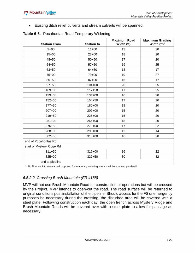
Plan of Development Mountain Valley Pipeline Project
November 30, 2017 6-29
Existing ditch relief culverts and stream culverts will be spanned.
Table 6-6. Pocahontas Road Temporary Widening
Station From Station to Maximum Road
Width (ft) Maximum Grading
Width (ft)1 9+00 11+00 13 20 15+00 23+00 18 20 48+50 50+50 17 20 54+50 57+50 19 25 63+50 64+50 13 17 75+00 79+00 19 27 85+50 87+00 15 17 97+50 104+00 20 25 109+00 117+50 17 25 129+00 134+00 16 20 152+00 154+50 17 30 177+50 180+00 18 20 207+00 209+00 15 20 219+50 226+00 15 20 251+00 266+00 18 20 276+50 279+00 17 22 288+00 293+00 12 14 302+50 310+00 16 20
end of Pocahontas Rd start of Mystery Ridge Rd
311+50 317+00 16 22 325+00 327+50 30 32
end at pipeline 1 - No fill or cut into stream bed proposed for temporary widening, stream will be spanned per detail
6.5.2.2 Crossing Brush Mountain (FR #188)
MVP will not use Brush Mountain Road for construction or operations but will be crossed by the Project. MVP intends to open-cut the road. The road surface will be returned to original conditions post installation of the pipeline. Should access for the FS or emergency purposes be necessary during the crossing, the disturbed area will be covered with a steel plate. Following construction each day, the open trench across Mystery Ridge and Brush Mountain Roads will be covered over with a steel plate to allow for passage as necessary.
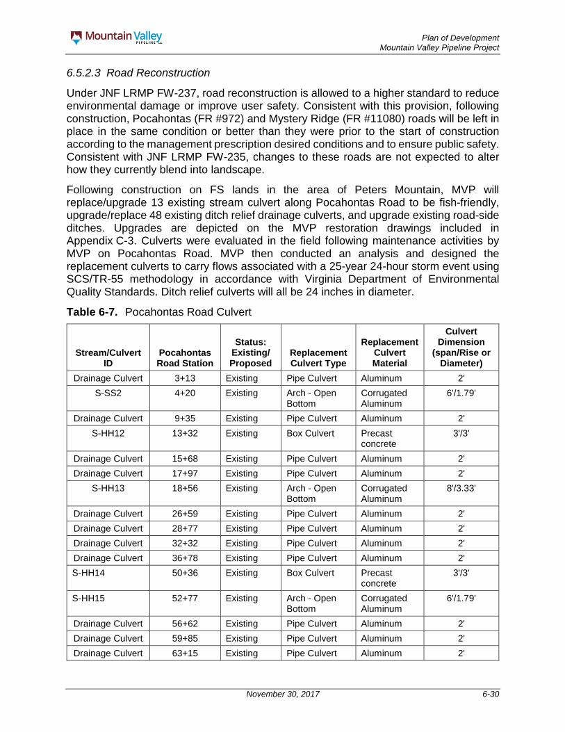
Plan of Development Mountain Valley Pipeline Project
November 30, 2017 6-30
6.5.2.3 Road Reconstruction
Under JNF LRMP FW-237, road reconstruction is allowed to a higher standard to reduce environmental damage or improve user safety. Consistent with this provision, following construction, Pocahontas (FR #972) and Mystery Ridge (FR #11080) roads will be left in place in the same condition or better than they were prior to the start of construction according to the management prescription desired conditions and to ensure public safety. Consistent with JNF LRMP FW-235, changes to these roads are not expected to alter how they currently blend into landscape.
Following construction on FS lands in the area of Peters Mountain, MVP will replace/upgrade 13 existing stream culvert along Pocahontas Road to be fish-friendly, upgrade/replace 48 existing ditch relief drainage culverts, and upgrade existing road-side ditches. Upgrades are depicted on the MVP restoration drawings included in Appendix C-3. Culverts were evaluated in the field following maintenance activities by MVP on Pocahontas Road. MVP then conducted an analysis and designed the replacement culverts to carry flows associated with a 25-year 24-hour storm event using SCS/TR-55 methodology in accordance with Virginia Department of Environmental Quality Standards. Ditch relief culverts will all be 24 inches in diameter.
Table 6-7. Pocahontas Road Culvert
Stream/Culvert ID
Pocahontas Road Station
Status: Existing/ Proposed
Replacement Culvert Type
Replacement Culvert Material
Culvert Dimension
(span/Rise or Diameter)
Drainage Culvert 3+13 Existing Pipe Culvert Aluminum 2' S-SS2 4+20 Existing Arch - Open
Bottom Corrugated Aluminum
6'/1.79'
Drainage Culvert 9+35 Existing Pipe Culvert Aluminum 2' S-HH12 13+32 Existing Box Culvert Precast
concrete 3'/3'
Drainage Culvert 15+68 Existing Pipe Culvert Aluminum 2' Drainage Culvert 17+97 Existing Pipe Culvert Aluminum 2'
S-HH13 18+56 Existing Arch - Open Bottom
Corrugated Aluminum
8'/3.33'
Drainage Culvert 26+59 Existing Pipe Culvert Aluminum 2' Drainage Culvert 28+77 Existing Pipe Culvert Aluminum 2' Drainage Culvert 32+32 Existing Pipe Culvert Aluminum 2' Drainage Culvert 36+78 Existing Pipe Culvert Aluminum 2' S-HH14 50+36 Existing Box Culvert Precast
concrete 3'/3'
S-HH15 52+77 Existing Arch - Open Bottom
Corrugated Aluminum
6'/1.79'
Drainage Culvert 56+62 Existing Pipe Culvert Aluminum 2' Drainage Culvert 59+85 Existing Pipe Culvert Aluminum 2' Drainage Culvert 63+15 Existing Pipe Culvert Aluminum 2'

Plan of Development Mountain Valley Pipeline Project
November 30, 2017 6-31
Stream/Culvert ID
Pocahontas Road Station
Status: Existing/ Proposed
Replacement Culvert Type
Replacement Culvert Material
Culvert Dimension
(span/Rise or Diameter)
S-MN20 77+51
Ford - to be spanned
Drainage Culvert 93+33 Existing Pipe Culvert Aluminum 2' Drainage Culvert 94+24 Existing Pipe Culvert Aluminum 2' Drainage Culvert 96+05 Existing Pipe Culvert Aluminum 2' Drainage Culvert 98+00 Existing Pipe Culvert Aluminum 2' S-HH16 101+40
Ford - to be spanned
Drainage Culvert 103+20 Existing Pipe Culvert Aluminum 2' Drainage Culvert 105+22 Existing Pipe Culvert Aluminum 2' Drainage Culvert 109+26 Existing Pipe Culvert Aluminum 2' Drainage Culvert 110+40 Existing Pipe Culvert Aluminum 2' Drainage Culvert 112+19 Existing Pipe Culvert Aluminum 2' S-UU11 114+90 Existing Pipe Culvert Aluminum 2' Drainage Culvert 118+19 Existing Pipe Culvert Aluminum 2' Drainage Culvert 121+29 Existing Pipe Culvert Aluminum 2' Drainage Culvert 124+11 Existing Pipe Culvert Aluminum 2' Drainage Culvert 126+55 Existing Pipe Culvert Aluminum 2' S-UU9 130+00 Existing Box Culvert Precast
concrete 12'/6'
Drainage Culvert 133+12 Existing Pipe Culvert Aluminum 2' Drainage Culvert 135+45 Existing Pipe Culvert Aluminum 2' Drainage Culvert 138+27 Existing Pipe Culvert Aluminum 2' Drainage Culvert 140+97 Existing Pipe Culvert Aluminum 2' S-PP19 152+60 Existing Box Culvert Precast
concrete 8'/4'
Drainage Culvert 157+10 Existing Pipe Culvert Aluminum 2' S-PP18 178+59 Existing Box Culvert Precast
concrete 9'/4'
Drainage Culvert 183+91 Existing Pipe Culvert Aluminum 2' Drainage Culvert 187+88 Proposed Pipe Culvert Aluminum 2' Drainage Culvert 191+64 Proposed Pipe Culvert Aluminum 2' Drainage Culvert 194+89 Proposed Pipe Culvert Aluminum 2' Drainage Culvert 198+14 Existing Pipe Culvert Aluminum 2' Drainage Culvert 200+24 Existing Pipe Culvert Aluminum 2' Drainage Culvert 204+02 Proposed Pipe Culvert Aluminum 2' Drainage Culvert 205+99 Proposed Pipe Culvert Aluminum 2' Drainage Culvert 212+05 Existing Pipe Culvert Aluminum 2'

Plan of Development Mountain Valley Pipeline Project
November 30, 2017 6-32
Stream/Culvert ID
Pocahontas Road Station
Status: Existing/ Proposed
Replacement Culvert Type
Replacement Culvert Material
Culvert Dimension
(span/Rise or Diameter)
Drainage Culvert 216+27 Existing Pipe Culvert Aluminum 2' Drainage Culvert 218+79 Proposed Pipe Culvert Aluminum 2' Drainage Culvert 221+16 Existing Pipe Culvert Aluminum 1.5' S-PP17 222+21 Existing Box Culvert Precast
concrete 3'/3'
Drainage Culvert 225+31 Existing Pipe Culvert Aluminum 2' Drainage Culvert 228+52 Proposed Pipe Culvert Aluminum 2' Drainage Culvert 231+84 Proposed Pipe Culvert Aluminum 2' Drainage Culvert 234+78 Existing Pipe Culvert Aluminum 2' Drainage Culvert 237+74 Proposed Pipe Culvert Aluminum 2' Drainage Culvert 240+52 Proposed Pipe Culvert Aluminum 2' Drainage Culvert 243+54 Existing Pipe Culvert Aluminum 2' Drainage Culvert 247+83 Proposed Pipe Culvert Aluminum 2' Drainage Culvert 251+68 Proposed Pipe Culvert Aluminum 2' Drainage Culvert 254+30 Existing Pipe Culvert Aluminum 2' Drainage Culvert 255+64 Existing Pipe Culvert Aluminum 2' Drainage Culvert 259+64 Existing Pipe Culvert Aluminum 2' S-PP14 264+47 Existing Box Culvert Precast
concrete 10'/4'
Drainage Culvert 268+19 Proposed Pipe Culvert Aluminum 2' Drainage Culvert 271+75 Proposed Pipe Culvert Aluminum 2' Drainage Culvert 275+44 Proposed Pipe Culvert Aluminum 2' S-PP15 278+25 Existing Box Culvert Precast
concrete 10'/4'
Drainage Culvert 281+32 Proposed Pipe Culvert Aluminum 2' Drainage Culvert 284+33 Proposed Pipe Culvert Aluminum 2' Drainage Culvert 287+43 Proposed Pipe Culvert Aluminum 2' Drainage Culvert 290+47 Existing Pipe Culvert Aluminum 2' Drainage Culvert 293+40 Existing Pipe Culvert Aluminum 2' Drainage Culvert 297+24 Existing Pipe Culvert Aluminum 2' Drainage Culvert 297+78 Existing Pipe Culvert Aluminum 2' Drainage Culvert 300+26 Existing Pipe Culvert Aluminum 2' Drainage Culvert 301+52 Existing Pipe Culvert Aluminum 2' Drainage Culvert 302+62 Existing Pipe Culvert Aluminum 2' Drainage Culvert 306+63 Proposed Pipe Culvert Aluminum 2'

Plan of Development Mountain Valley Pipeline Project
November 30, 2017 6-33
6.6 Contingency Planning MVP will maintain constant oversight of the ANST boring operation. Should the conventional bore under the ANST fail as described in the Contingency Plan for the Proposed Crossing of the Appalachian National Scenic Trail (Appendix E), MVP will notify and seek approval from FERC and FS to utilize the alternative bore methods described in Appendix E. No motorized vehicle traffic is permitted between the Appalachian National Scenic Trail bore pits. However, construction and operations personnel may walk between the pits as needed to complete inspections. If leveling is required, the area affected will be returned to the preconstruction contours.
6.7 Safety Requirements MVP construction contractors are required to develop and submit Site-Specific Emergency Action Plans (SSEAP) prior to the start of construction activities. The SSEAP will identify potential hazards including detailed plans to prevent, mitigate and/or eliminate the hazards as well as emergency response procedures for potential event. The plan will also identify potential hazard scenarios. Construction contractors will be responsible for training all employees, and agency representatives that will be present on site during construction. SSEAP’s will be thoroughly vetted by MVP and shared with the FS and CIC as discussed in the Framework Construction Emergency Preparedness and Response Plan in Appendix Q.
At all locations where the general public can access the construction perimeter, such as roads and trails, high-visibility warning signs will be installed before and at the point of entry. Warning signs are typically no smaller than two feet by two feet and come in various high-visibility colors. The construction perimeter will also be flagged in high-visibility colors, and if needed, safety fencing. Mountain Valley will also post public announcement on FS-JNF existing information kiosks, any new information kiosks determined necessary by the FS, and the FS-JNF website (Alerts & Warnings), as permitted by the FS. MVP will also place construction notifications related to federal properties in the local papers in Giles, Craig, and Montgomery counties. MVP will also provide the construction notices to the BLM and USACE to post on their public notification sites.
While construction vehicles are using Pocahontas Road (FR #972), MVP will take precautions to protect hikers utilizing the ANST in the area where the ROW bores under the ANST and where a small section of Pocahontas Road near Clendennin Road is utilized by hikers as part of the ANST. In this area of Pocahontas Road, Mountain Valley will ensure the safety of hikers by employing traffic flaggers to coordinate truck and hiker traffic. Hikers will be stopped in 10 minute intervals to allow for trucks to pass before continuing on Pocahontas Road.
MVP will post warning signs at these locations, will have safety and security personnel monitoring traffic on Pocahontas Road, and will implement a speed limit of 10 miles per hour.
MVP will provide security staffing during construction of the Project. This will include an officer at an offsite construction lay down area to provide security outside of the JNF and a second mobile officer at the construction site. A mobile security supervisor will be in the

Plan of Development Mountain Valley Pipeline Project
November 30, 2017 6-34
area and available to monitor and assist as needed. Construction contractors will be required to provide their own security officers to monitor their equipment and assist with construction activities such as safety over watch, off road traffic control, and visitor monitoring.
Safety during operations and maintenance is discussed in Section 9 and Appendix R.

Plan of Development Mountain Valley Pipeline Project
November 30, 2017 7-1
7.0 RESOURCE VALUES AND ENVIRONMENTAL CONCERNS
This section provides a brief summary of the procedures proposed in the Environmental Protection Plans included as appendices to this POD that MVP will use to ensure environmental protection during construction, operation, and maintenance. The Environmental Protection Plans are stand-alone documents that contain complete lists of all environmental protection measures and other specific stipulations and methods for that environmental resource. MVP will ensure their contractors and employees implement these measures.
The Environmental Compliance Management Plan, included as Appendix N to this POD, is the primary guidance document that states how MVP will uphold, document, and manage compliance with the Right-of-Way Grant, the POD, and all federal, state, and local permits. It is a centralized Project environmental compliance reference and is intended to facilitate environmental compliance. It describes the following essential elements:
• Roles and responsibilities of the participants; • Comprehensive inspection and monitoring program; • Corrective procedures in the event of non-compliance; • Standard protocol for variance requests, exceptions, and other deviations; • Communication plan; • Reporting process; and • Comprehensive Project-specific environmental compliance training program.
The Environmental Compliance Management Plan is intended to be revised as needed throughout the construction process.
7.1 Soils and Vegetation The Project has potential to impact soils and vegetation; as a result, environmental protection measures have been developed to minimize potential impacts on these resources and will be applied, as applicable, to the Project.
The Project Restoration Plan (Appendix H to the POD) focuses on the stabilization and protection of existing vegetation and soils, minimizing disturbance of the environment to the extent practical, and establishing vegetation communities that are consistent and compatible with adjacent land uses. The goal of this plan is to provide a structure for developing and implementing the Project’s restoration process on the JNF, which will be designed to restore impacted areas to meet the following objectives:
• Topsoil segregation and stockpiling; • ROW stabilization and restoration; • Seedbed preparation and re-seeding; • Noxious- and invasive-weed control; and

Plan of Development Mountain Valley Pipeline Project
November 30, 2017 7-2
• Road reclamation.
7.2 Exotic and Invasive Species Control The FS developed a National Strategic Framework for Invasive Species Management in 2013 to guide the FS in responding to the invasive species problem in the United States. This guidance document identifies the most significant strategic actions that should be undertaken to reduce the threat of invasive species (FS 2013). The FS’s national strategy encompasses four program elements:
• Prevention; • Detection; • Control and management; and • Restoration and rehabilitation.
The Exotic and Invasive Species Control Plan (Appendix S to this POD) is based on this guidance document, as well as the procedures and measures identified in FERC’s Plan, and was prepared with the support of the Wildlife Habitat Council. The Exotic and Invasive Species Control Plan presents methods to control the potential occurrence/infestation of noxious and invasive weeds, including herbicides, during and following construction of the Project. The purpose of the plan is to ensure noxious weeds are identified and controlled during the construction of Project facilities and all federal, state, and county requirements are satisfied. Pursuant to the FS’s request, MVP has also developed an Herbicide Usage Plan (Appendix T).
7.3 Water Quality 7.3.1 Stormwater Pollution Prevention The Stormwater Pollution Prevention Plan for Virginia (Appendix U to this POD) will serve as a guidance document to be used during development of the site-specific erosion and sedimentation control plans and stormwater management plan in Virginia in an effort to reduce stormwater discharge associated with construction of the Project. This document is currently in review with the Virginia Department of Environmental Quality and will be provided once approved. The Stormwater Pollution Prevention Plan for West Virginia is included within the Erosion and Sedimentation Control Plan (Attachment C-1).
7.3.2 Spill Prevention, Containment, and Countermeasures The SPCC Plan and Unanticipated Discovery of Contamination Plan (Appendix D to this POD) describes preventive measures, such as personnel training, equipment inspection, and refueling procedures, to reduce the likelihood of spills. It also describes mitigation measures, such as containment and cleanup, to minimize potential impacts if a spill occurs.
7.3.3 Impact Avoidance and Minimization To minimize impacts to water resources, Mountain Valley reduced the temporary construction ROW at waterbody and wetland crossings from 125 feet to 75 feet. Clearing activities within riparian buffer areas will also be restricted to the 75-foot temporary

Plan of Development Mountain Valley Pipeline Project
November 30, 2017 7-3
construction ROW. Buffer areas for each waterbody and wetland will extend approximately 50 feet, where possible, from where the pipeline trench enters the waterbody or wetland area. The resource crossing and associated buffer areas will be treated as separate construction entities, except during clearing activities, and efforts will be made to cross these areas during low-flow conditions to the extent practicable. All Project waterbody crossings will be conducted using open-cut dry-ditch methods (flume pipe, dam and pump, or combination thereof) so that no in-stream work will be conducted in a flowing watercourse. Temporary equipment crossings will be completed via timber mat or equipment bridges to avoid impacts if no existing culvert is present. The spoils from the crossing will be required to be outside of the riparian corridor where the distance varies by flow type and slope. Spoil will be required to be 100 feet from a perennial stream, 50 feet from an intermittent stream and 25 feet from an ephemeral channel.
Once grubbing and grading starts at a waterbody or wetland crossing, it will be actively conducted for consecutive days until the crossing is completed and the work area is restored. In general, the same measures utilized for upland construction also apply to waterbody and wetland crossings. Sediment barriers will be installed immediately after initial disturbance of the waterbody or adjacent upland area in accordance with the Annual Standards and Specifications (Appendix C-2 to this POD). Sediment barriers will be properly maintained throughout construction and reinstalled as necessary (such as after backfilling of the trench) until replaced by permanent erosion controls or restoration of adjacent upland areas is complete. Sediment barriers will be installed across the entire construction ROW at all waterbody crossings. Where waterbodies are adjacent to the construction ROW, sediment barriers will be installed along the edge of the construction ROW as necessary to contain spoil and sediment within the ROW. Trench plugs will be used at all waterbody crossings to prevent diversion of water into upland portions of the pipeline trench and to keep any accumulated trench water out of the waterbody. Trench plugs will be of sufficient size to limit water flow along the trench. Permanent slope breakers will be installed in all areas of the Project including 25 feet from all waterbody boundaries to minimize potential for erosion to occur within the riparian buffer areas. Should any erosion and sediment control measures be found to be ineffective, Mountain Valley will revise the BMP installation or implement additional controls to correct the deficiency.
During project activities on National Forest lands, Mountain Valley will conduct project construction activities in a manner that minimizes duration of disturbance in all areas including steep slopes. Construction will be completed in streams during low-flow and within the regulatory timeframes.
7.4 Plant and Wildlife Conservation The Plant and Wildlife Conservation Measures Plan (Appendix V to this POD) presents the measures proposed by the MVP for avoidance and minimization of impacts to plant and wildlife species as related to construction activities for the Project and outlines specific conservation measures to be implemented in the event that state or federally listed species, FS special status species, or their habitats are identified within or adjacent to the Project ROW.

Plan of Development Mountain Valley Pipeline Project
November 30, 2017 7-4
The plan includes information on (1) regulatory requirements and agency concerns pertaining to biological resources, (2) avoidance and minimization conducted during siting and routing of the Project to avoid impacts to biological resources, and (3) specific environmental protection measures to be implemented if state- or federally listed species, BLM sensitive species, or FS sensitive species or their habitats are identified within, or adjacent to, the Project ROW. In addition, the plan addresses general wildlife including big game, raptors, and migratory birds. Table 7-1 identifies time of year restrictions related to sensitive species.
Table 7-1 Time of Year Restrictions on Jefferson National Forest lands crossed by the proposed Mountain Valley Pipeline.
Species Time of Year Restriction a/ Migratory Birds April 1 – July 31 Indiana bat and Northern long-eared bat June 1 – July 31 Northern long-eared bat (within 0.25-mile radius around entrance to Tawney’s Cave) April 1 – November 14
UNT to Craig Creek, S-PP20 b/ March 1 – July 31 UNT to Craig Creek, S-PP21 b/ March 1 – July 31 UNT to Craig Creek, S-PP22 b/ March 1 – July 31 UNT to Craig Creek, S-HH18 b/ March 1 – July 31 Kimballton Branch, S-PP14 c/ October 1 – June 30 Stony Creek, S-OP1 c/ August 15 – July 31 Stony Creek, S-S5 c/ August 15 – July 31 Notes: a/ Time of year restrictions as specified by the U.S. Fish and Wildlife Service and the Virginia Department of Game and Inland Fisheries b/ Time of year restriction due to James spinymussel and Atlantic pigtoe c/ Time of year restriction due to cold-water and wild trout concerns d/ Time of year restriction due to Candy darter, Green floater, pistolgrip. The time of year restriction applies to in-stream activities; however, MVP will cross Stony Creek using the conventional bore method. No in-stream activities are proposed for the Stony Creek crossings.
MVP will monitor and record the success of revegetation on FS lands for five growing seasons or longer, until the FS has determined that revegetation has been successful and scenic integrity objectives have been met. MVP will submit a status report to the FS following each inspection. Should a stream bank’s vegetation not reestablish following five growing seasons, MVP will work with FS personnel to develop a plan for re-establishment, including monitoring requirements.
7.5 Health and Safety 7.5.1 Blasting The Blasting Plan (Appendix J to this POD) outlines the procedures and safety measures that the contractor will adhere to while implementing blasting activities during the construction of the Project. The need for blasting and the methods utilized are largely determined by type of rock encountered along the route. Blasting is likely to be needed in areas with hard and intact sedimentary bedrock (sandstones, limestones, and shales). Soft bedrock, such as weathered sandstones, limestones, and shales, may possibly be removed by ripping or mechanical means. Table 6-4 lists areas within the JNF where blasting may be necessary.

Plan of Development Mountain Valley Pipeline Project
November 30, 2017 7-5
The Blasting Plan discusses the regulatory requirements, plans for pre- and post-blasting inspections, and monitoring and mitigation measures.
7.5.2 Fugitive Dust Control The Fugitive Dust Control Plan (Appendix W to this POD) provides measures to ensure protection of the air quality that will be affected by the Project. This plan will be implemented during the construction, operation, and maintenance phases of the Project. These measures are intended to minimize dust and emissions from construction-related activities.
7.5.3 Fire Prevention and Suppression The Fire Prevention and Suppression Plan (Appendix X to this POD) includes measures to be taken by the MVP and its contractors to ensure that fire prevention and suppression measures are carried out in accordance with federal, state, and local regulations. The plan will address the specific requirements of the FS and provides BMPs for fire management on privately owned lands.
On the JNF, the use of dozers for fire line construction over the pipeline would present no hazards, but would require a post-wildfire inspection of the remaining depth of cover above the pipeline. Construction of fire lines with explosives within 200 feet of the pipeline would be prohibited if 24-hours’ notice cannot be not given and/or if other precautionary measures cannot be met.
Prescribed fires in the JNF would not affect pipeline integrity. When a prescribed fire is being planned by the FS, communication with MVP should occur so the plastic surface line markers can be removed during the event and replaced when completed. In the event a fire, planned or unplanned, was to occur on the surface in the vicinity of the pipeline, the presence of the pipeline would not increase fire hazards. Fires on the surface are not a direct threat to underground natural gas pipelines because of the insulating effects of soil cover over the pipeline.
7.5.4 Hazardous Materials Management The Hazardous Materials Management Plan (Appendix Y to this POD) includes measures to reduce the risks associated with the use, storage, transportation, production, and disposal of hazardous materials (including hazardous substances and wastes). This plan identifies Project-specific mitigation measures and other specific stipulations and methods to address spill prevention, response, and cleanup procedures for the Project.
7.5.5 Construction Emergency Preparedness and Response The Framework for Construction Emergency Preparedness and Response Plan (Appendix Q to this POD) provides an overview of methods to be implemented if the need for emergency management is imminent. This framework describes the existing support structure, chain of command, and emergency communications protocols.
7.5.6 Operations, Maintenance, and Emergency Response The Operations, Maintenance, and Emergency Response Plan (Appendix R) includes measures to be employed while conducting routine, corrective, and emergency

Plan of Development Mountain Valley Pipeline Project
November 30, 2017 7-6
operations and maintenance activities. Measures identified will be in compliance with applicable state and federal laws and policies allowing for the MVP to access the pipeline ROW in a timely, cost effective, and safe manner.
7.5.7 Framework Flagging, Fencing, and Signage The Framework Flagging, Fencing, and Signage Plan (Appendix Z to this POD) describes the methods that will be used in the field to delineate the Project limits of disturbance and protect sensitive environmental and cultural resources during Project construction. These methods are intended to ensure MVP personnel, the construction contractor(s), the BLM, FS, USACE, CIC, and other monitors and visitors to the Project construction sites stay on approved access routes and within approved work areas. The measures described in this plan are an integral part of the environmental compliance program for avoiding and minimizing impacts to sensitive resources. The objective of this plan is to provide information on the field markings (i.e., flagging, fencing, and signage) that will be used to identify approved Project travel and work areas, as well as sensitive resource areas where construction or travel is to be excluded.
7.6 Cultural and Historic Resources The Plan for Unanticipated Historic Properties and Human Remains (Appendix O to this POD) identifies the protocols MVP will implement if historic properties or human remains (an unanticipated discovery) are discovered during construction activities. Also see the Framework Flagging, Fencing, and Signage Plan (Appendix Z to this POD), which describes the methods that will be used in the field to delineate limits of disturbance and protect sensitive cultural resources during Project construction.
7.7 Unanticipated Discovery of Paleontological Resources The Plan for Unanticipated Discovery of Paleontological Resources (Appendix P to this POD) identifies the protocols MVP will implement if paleontological resources (an unanticipated discovery) are discovered during construction activities. Also see the Framework Flagging, Fencing, and Signage Plan (Appendix Z to this POD), which describes the methods that will be used in the field to delineate limits of disturbance and protect sensitive cultural resources during Project construction.
7.8 Off-Highway Vehicle Control and Access The Off-Highway Vehicle Management Plan (Appendix AA to this POD) discusses methods to limit off-highway vehicle (OHV) use within the ROW in order to avert user conflicts in adjacent areas, as well as to avoid problems with revegetation efforts and prevent potential erosion within the ROW. To minimize OHV access within the ROW, MVP will install barriers at appropriate locations in coordination with the JNF. The proposed OHV barriers will be designed and constructed in a manner that attempts to prevent unauthorized motor vehicle/OHV use of and along the ROW, but will still allow the passage of wheelchairs or any device that meets the legal definition of a wheelchair in areas where a gate, barrier, or berm is installed on a road to close it to motorized traffic, but foot travel is encouraged beyond the gate or barrier.
Plan of Development Mountain Valley Pipeline Project
November 30, 2017 7-7
7.9 Scenery Mitigation To ensure compliance with Scenic Integrity Objectives (SIOs) in the Jefferson National Forest, MVP will implement the following mitigation measures and BMPs, which MVP developed in consultation with FS, to lower potential visual impacts from the Project identified during the analysis.
In the following areas, MVP will undulate the construction ROW edges to achieve the effect shown in Figure 7-1 to ensure that vegetative openings appear more natural and conform to the natural form, line, color, and texture of the existing landscape. These areas have a High or Moderate SIO and were identified in the FEIS as requiring mitigation in order to meet those SIOs.
o Top of Peters Mountain – milepost 196.25 to the bore pit on north side of mountain.
o Top of Peters Mountain – from the bore pit on the south side of the mountain to milepost 197.8 on Mystery Ridge.
o Crest of Sinking Creek Mountain – milepost 218.52 to reduce visibility of the “notch” in the trees at the top of the mountain.
o The north side of Brush Mountain – mileposts 219.7 to 220.75. Temporary work spaces within forested areas would include some level of shrub
plantings or shrub seed mixes to soften the hard edge formed between the existing/undisturbed forest and the maintained ROW. MVP intends to include woody seed mixes within temporary areas where forest regeneration is desired.
Road or trail crossings will be done at a right angle, where feasible, to ensure the shortest duration of view for the crossing (FS 1975).
Revegetate the construction and permanent operational rights-of-way as shown in the concept diagram provided in Figure 7-2. This entails maintaining an herbaceous strip 10-foot wide centered over the pipeline, and performing trimming or selective cutting of trees over 15-foot-tall within a 30-foot-wide strip centered over pipeline. Outside the 10-foot-wide strip, the remainder of the construction and permanent right-of-way would be revegetated through the use of acceptable seed mixes, pollinator plants, shrubs and trees in accordance with FERC’s Procedures. Particularly along the edge of this herbaceous linear opening, a variety of sizes and species of vegetation would be planted in a manner that breaks up the straight, parallel edges of the corridor and reduces the hard shadow line that can draw the viewer’s attention.
MVP shall have a landscape architect on-site to monitor for activities pertaining to scenery including but not limited to undulating the construction right-of-way edges in areas identified above, and monitoring growth of vegetation from a variety of viewpoints to assure scenic integrity objectives are met within five years.
The ANST will be crossed by the Project by using a conventional bore method to ensure there will be no disruptions to hikers on the ANST.

Plan of Development Mountain Valley Pipeline Project
November 30, 2017 7-8
Figure 7-1. ROW Clearing Pattern for Vegetation Feathering Technique
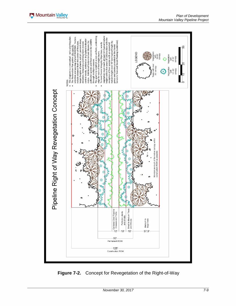
Plan of Development Mountain Valley Pipeline Project
November 30, 2017 7-9
Figure 7-2. Concept for Revegetation of the Right-of-Way

Plan of Development Mountain Valley Pipeline Project
November 30, 2017 7-10
MVP will install the pipe via conventional bore under the ANST, leaving an approximate area of no disturbance of 307 feet on the south side of the trail and 273 feet on the north side of the trail where tree clearing and land disturbance will not occur. The areas of no disturbance of 307 feet on the south side and 273 feet on the north side of the ANST refer to those between the safety fence that will be installed in front of the bore pits and the ANST. These barriers will be set up approximately ten feet in front of each bore pit to provide for the safety of workers and visitors to the ANST during construction activities. Thus, there is approximately 600 feet between the bore pits, eliminating visibility of the ROW to trail users at the crossing location.
MVP has sited the alignment to conform to the natural lines in the landscape and followed existing ROWs, where feasible.
Short-term impacts will include the visible evidence of temporary construction activities, such as vegetation clearing; color contrast of soil in the cleared ROW or along other ancillary structures such as roads; and the presence of vehicles and workers. With the mitigation measures of feathering (scalloping or undulating) the edges of the construction right-of-way and revegetation of the construction and permanent rights-of-way after construction, the project is expected to meet all of the Scenic Integrity Objectives.

Plan of Development Mountain Valley Pipeline Project
November 30, 2017 8-1
8.0 STABILIZATION AND REHABILITATION
8.1 Restoration (Soil Replacement and Stabilization) As requested by the FS, topsoil within the ROW and construction disturbance footprint on the JNF will be segregated from subsoils. This segregated topsoil will be replaced over the subsoils after the trench is backfilled and prior to restoration and revegetation effort. Soils that have been compacted by construction equipment traffic will be decompacted via disking. No additional soil materials will be brought onto the JNF from outside the NFS lands.
Soils will be initially stabilized during construction through the use of temporary erosion control devices. Following construction, the surface of the ROW disturbed by construction will be graded to match original contours to the greatest extent practicable and to be compatible with surrounding drainage patterns, except at those locations where permanent changes in drainage will be required to prevent erosion, scour, and possible exposure of the pipeline. Soils will then be decompacted (as described above), and permanent erosion control measures will be installed at this time. Temporary construction erosion control measures may also be left in place following construction until sufficient vegetative cover is re-established to prevent significant erosion and sedimentation (see Appendix C for more details regarding erosion control devices).
Successful restoration and revegetation of disturbed areas is a critical component of soil stabilization. Restoration and soil stabilization will be considered successful if construction debris is removed (unless requested otherwise by the FS), revegetation is successful, proper drainage has been restored, and the appropriate federal and state agencies agree that the restoration efforts were successful (see Appendix H for more details regarding restoration and revegetation). Following construction, MVP will monitor and record the success of revegetation on FS-managed lands for up to five growing seasons or until the area is 80 percent revegetated. Inspection frequency will be at least annually. MVP will submit a status report to the FS following each inspection. Should the vegetation in an area not reestablish following five growing seasons, MVP will work with FS personnel to develop a plan for re-establishment, including monitoring requirements.
All soil stabilization and restoration activities located on NFS lands shall be completed to accepted federal, state, and local BMPs and to the satisfaction of the FS Authorizing Officer in charge. In addition, as-built drawings of the segments crossing NFS lands will be provided to the FS, and all National Forest boundary monuments disturbed or damaged within the Project area will be re-established upon completion of installing the pipe and establishing the ROW corridor.
8.2 Disposal of Vegetation Removed During Construction Once removal has begun, timber will be cut into usable lengths and stacked adjacent to the ROW in accordance with the FS requirements (Appendix I). Stumps will be cut as close to the ground as feasible and left in place, except for in areas directly over the trenchline. Merchantable timber will be hauled away and sold. All non-merchantable brush and slash will remain on the right-of-way until pipeline construction activities begin,

Plan of Development Mountain Valley Pipeline Project
November 30, 2017 8-2
utilized in downslope areas of the ROW and/or removed from the area in accordance with FS requirements.
Non-merchantable brush and slash will be retained on site to provide a level of erosion control until actual pipeline construction begins, at which time it will be windrowed to the edge of the right-of-way. Windrowing of non-merchantable brush and slash along the ROW will result in habitat for many types of wildlife including: rabbits and other small mammals, ruffed grouse, song birds and reptiles and provide food for insects. The windrows can also serve as escape cover from predators as well as locations for nesting and shelter from inclement weather. The windrows should be restricted to 8 feet tall, 20 feet wide, and 100 feet long with a 50-foot break between piles in order to provide fire breaks and wildlife crossings. Non-merchantable brush and slash can be utilized in downslope areas of the ROW and access roads to aide in soil stabilization and erosion control. Layering the brush and slash at the toe of a low-side slope along an access road provides soil stabilization, and erosion and sediment control. Layering of brush and slash can promote physical protection to the downslope areas of the ROW. Additionally, the layering can provide long-term support for revegetation in downslope areas of the ROW.
8.3 Seeding Specifications MVP consulted with the FS regarding appropriate seed mixtures for use within the JNF. The FS indicated that the initial goal of seeding on the JNF is to establish vegetative cover to minimize surface erosion and sedimentation, while the secondary goal is to establish an assortment of native species congruent with local ecological communities and beneficial for wildlife and pollinators. Native plants that provide structural diversity and wildlife/pollinator benefits often do not germinate or grow fast enough to provide initial erosion control; therefore, these goals will be accomplished through the use of seed mixes that include both fast growing, annual/short-lived perennial non-native grass species provided by the FS on November 21, 2016, as well as some perennial native species. Specifics regarding the seed mixes that would be used as well as the preparation of seed beds and seeding methods that would be used are described in the Restoration Plan (Appendix H to the POD) and the Plant and Wildlife Conservation Plan (Appendix V of the POD).
8.4 Fertilizer Dry fertilizer and lime will be incorporated into the top two to five inches of soil by disking or other means. The following are guidelines for fertilizer and lime application rates recommended by the FS:
Fertilizer: – 600 – 800 lbs/acre of 10-20-10 (Nitrogen [N], Phosphorous [P], Potassium
[K]) fertilizer); – 400 lbs/acre of 15-30-15 (N-P-K) fertilizer; or – 800-1,000 lbs/acre of 10-10-10 (N-P-K)
Lime: – 1,500-4,000 lbs/acre (pelletized or dust); or

Plan of Development Mountain Valley Pipeline Project
November 30, 2017 8-3
– 4,000 lbs/acre of Hydro Lime (2.5 gal container is equivalent to 1000 lbs limestone; 5-10 containers/acre).
Soil chemistry tests will be conducted during construction and the fertilizer and liming rates described above will be adjusted accordingly based on the results of site-specific soil tests. Soil chemistry data will be submitted to the FS following testing and any modifications to the fertilizer or lime application rates described above will be provided to the FS for approval prior to use (see the Restoration Plan; Appendix H to the POD).
8.5 Limiting Access to the ROW and Law Enforcement Appendix AA discusses the measures MVP proposes to control access to the ROW during operation. FS Law Enforcement concerns involve poaching, illegal ATV-OHV usage, violations of the Archaeological Resources Protection Act, dumping, and other illegal activities that may increase by utilizing the pipeline corridor. A plan for monitoring involving both FS Law Enforcement and Heritage Program personnel will be provided to MVP. Once agreed upon, the plan for monitoring will be included in the communication plan.The Heritage Program will require an incremental or phased monitoring plan of the archaeological resources located adjacent to the proposed corridor and will be implemented by FS archaeologists to meet SHPO and Tribal Historic Preservation Office programmatic agreement demands. FS Law Enforcement concerns covering a constant monitoring of the areas will need to be implemented to ensure public safety and protection of forest resources. Monitoring of forest and cultural resources will be conducted by the FS and funded through cost recovery.
8.6 Access Road Reclamation No new roads will be built on the JNF for this Project. Two existing FS roads, Pocahontas Road (FR #972) and Mystery Ridge Road (FR #11080), will be improved for use during construction. MVP has included Pocahontas and Mystery Ridge Road in the alignment sheets and erosion and sedimentation control sheets (Appendix C-3). The alignment sheets show areas in which roads are expected to be improved or extended. Improved means that MVP will expand, widen, or grade the access road. MVP does not intend to utilize or perform any work on the northwestern portion of Mystery Ridge Road (FR #11080) west of pipeline milepost 196.9 where the pipeline ROW first intersects with this road from the west. These roads will be returned to original or better condition upon completion of the pipeline construction as discussed in section 6.5. Temporary erosion control measures will be removed upon final stabilization and approval from applicable federal and state agencies and installation of permanent erosion control measures. MVP will not use Brush Mountain Road (FR #188) for construction or operation traffic. Signage will be posted during construction letting construction traffic know that Brush Mountain Road cannot be utilized.

Plan of Development Mountain Valley Pipeline Project
November 30, 2017 9-1
9.0 OPERATION AND MAINTENANCE
Following construction of the Project facilities, certain areas along the pipeline alignment will comprise permanent ROW or facility sites. For pipeline facilities, MVP will maintain a typical permanent ROW easement of 50 feet in width. In some locations, it will be necessary to retain access roads used for construction to support ongoing pipeline operations as discussed in Section 9.1.
MVP will operate and maintain the Project in compliance with PHMSA regulations provided at 49 CFR Part 192, FERC regulations at 18 CFR § 380.15, and maintenance provisions of FERC’s Plan and Procedures (FERC 2013a, 2013b). In correspondence with the FS, MVP will use herbicides and pesticides to maintain the ROW or any of its Project facilities. Appendix X contains MVP’s Herbicide Use Plan, which identifies how herbicide used to control noxious weed and invasive species will be implemented on the JNF.
Pipeline Operational activity on the pipeline will be limited primarily to maintenance of the ROW and inspection, repair, and cleaning of the pipeline. All maintenance activities will be confined to the ROW. Periodic aerial and ground inspections by pipeline personnel will identify soil erosion that may expose the pipe; dead vegetation that may indicate a leak in the line; conditions of the vegetation cover and erosion control measures; encroachment on the ROW, such as buildings and other substantial structures; and other conditions that could present a safety hazard or require preventive maintenance or repairs.
A schedule for the maximum intervals between inspections/patrols by class area is provided in Table 9-1. The pipeline’s cathodic protection system will also be monitored and inspected in accordance with 49 CFR Part 192 requirements to ensure proper and adequate corrosion protection. The pipeline will be designed for internal inspection technology. Appropriate responses to conditions observed during internal inspections will be taken as necessary. In addition, class change studies will also occur to identify areas of development.
Vegetation on the permanent ROW will be maintained by mowing, cutting, and trimming. The permanent ROW will be allowed to revegetate; however, large brush and trees will be periodically removed in accordance with the FERC’s Plan and Procedures. In uplands, trees or deep-rooted shrubs could damage the pipeline’s protective coating, obscure periodic surveillance, or interfere with potential repairs and would not be allowed to grow within the permanent ROW. Along the length of the pipeline, including wetlands, MVP will maintain a 10-foot-wide strip over the pipeline in a herbaceous state. The construction and permanent operational rights-of-way will be revegetated as shown in the concept diagram provided in Figure 7-2. This entails maintaining an herbaceous strip 10-foot wide centered over the pipeline, and performing trimming or selective cutting of trees over 15-foot-tall within a 30-foot-wide strip centered over pipeline. Outside the 10-foot-wide strip, the remainder of the construction and permanent right-of-way would be revegetated through the use of acceptable seed mixes, pollinator plants, shrubs and trees in accordance with FERC’s Procedures. Particularly along the edge of this herbaceous
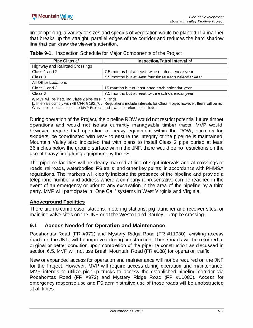
Plan of Development Mountain Valley Pipeline Project
November 30, 2017 9-2
linear opening, a variety of sizes and species of vegetation would be planted in a manner that breaks up the straight, parallel edges of the corridor and reduces the hard shadow line that can draw the viewer’s attention.
Table 9-1. Inspection Schedule for Major Components of the Project Pipe Class a/ Inspection/Patrol Interval b/
Highway and Railroad Crossings Class 1 and 2 7.5 months but at least twice each calendar year Class 3 4.5 months but at least four times each calendar year All Other Locations Class 1 and 2 15 months but at least once each calendar year Class 3 7.5 months but at least twice each calendar year a/ MVP will be installing Class 2 pipe on NFS lands b/ Intervals comply with 49 CFR § 192.705. Regulations include intervals for Class 4 pipe; however, there will be no Class 4 pipe locations on the MVP Project, and it was therefore not included.
During operation of the Project, the pipeline ROW would not restrict potential future timber operations and would not isolate currently manageable timber tracts. MVP would, however, require that operation of heavy equipment within the ROW, such as log skidders, be coordinated with MVP to ensure the integrity of the pipeline is maintained. Mountain Valley also indicated that with plans to install Class 2 pipe buried at least 36 inches below the ground surface within the JNF, there would be no restrictions on the use of heavy firefighting equipment by the FS.
The pipeline facilities will be clearly marked at line-of-sight intervals and at crossings of roads, railroads, waterbodies, FS trails, and other key points, in accordance with PHMSA regulations. The markers will clearly indicate the presence of the pipeline and provide a telephone number and address where a company representative can be reached in the event of an emergency or prior to any excavation in the area of the pipeline by a third party. MVP will participate in “One Call” systems in West Virginia and Virginia.
Aboveground Facilities There are no compressor stations, metering stations, pig launcher and receiver sites, or mainline valve sites on the JNF or at the Weston and Gauley Turnpike crossing.
9.1 Access Needed for Operation and Maintenance Pocahontas Road (FR #972) and Mystery Ridge Road (FR #11080), existing access roads on the JNF, will be improved during construction. These roads will be returned to original or better condition upon completion of the pipeline construction as discussed in section 6.5. MVP will not use Brush Mountain Road (FR #188) for operation traffic.
New or expanded access for operation and maintenance will not be required on the JNF for the Project. However, MVP will require access during operation and maintenance. MVP intends to utilize pick-up trucks to access the established pipeline corridor via Pocahontas Road (FR #972) and Mystery Ridge Road (FR #11080). Access for emergency response use and FS administrative use of those roads will be unobstructed at all times.
Plan of Development Mountain Valley Pipeline Project
November 30, 2017 9-3
MVP will comply with operations and maintenance measures in Appendix V (Plant and Wildlife Conservation Measures Plan) that address migratory birds and other species.
9.2 Hydrostatic Testing During Operation Hydrostatic testing will be performed along the portion of the pipe on the FS and USACE managed lands; however, no water will be withdrawn or released on FS or USACE managed lands. Should hydrostatic testing be necessary during operations of the Pipeline, no water will be withdrawn or released on FS or USACE managed lands.
9.3 Removal or Addition of Infrastructure during Pipeline Maintenance No pumps will be located on the FS or USACE managed lands. At this time, it is not expected that any replacement of pipe sections will be required on FS or USACE managed lands during operations. However, if any repairs are necessary, MVP would consult with the FS and USACE prior to the pipe repair.
9.4 Safety MVP and/or its designated contractor perform a number of activities to keep pipelines operational and in good repair. Most of these activities, such as routine patrols, inspections, and scheduled maintenance, are planned in advance. However, there could be an occasional need for emergency response in cases where public safety and property are threatened, to prevent imminent damage to the pipeline and ancillary facilities.
Routine, corrective, and emergency response activities will be conducted in accordance with this Operations, Maintenance, and Emergency Response Plan (Appendix R).
Mountain Valley will continue to coordinate with the FS to establish long-term monitoring of sensitive areas within, adjacent to, or in the vicinity of the Pipeline ROW.
9.5 Will Industrial Wastes and Toxic Substances be Generated or Stored on ROW
It is not anticipated that hazardous waste will be generated or stored during construction of the Project. However, if for any reason hazardous waste is created or uncovered during construction or operation of the Project, the SPCC Plan and the Unanticipated Discovery of Contamination Plan would identify methods for handling the waste. All waste would be disposed of per state and federal requirements (see Appendix Y).
9.6 Inspection and Maintenance Schedules An inspection and maintenance schedule is provided as Table 9-1. Additional information about Operations, Maintenance, and Emergency Response Plan (Appendix R).
9.7 Work Schedules Work schedules during operation and maintenance will be determined based on the necessary activity. An inspection and maintenance schedule is provided as Table 9-1.

Plan of Development Mountain Valley Pipeline Project
November 30, 2017 9-4
9.8 Fire Control The construction and operations contractors working on the Project will be required to implement the provisions of the Fire Plan (Appendix X). Additionally, each contractor will be required to prepare and implement an individual fire control plan, which will identify responsibilities and describe actions to be implemented by the contractor in the event of an inadvertent fire. Copies of each fire control plan will be appended to this Fire Plan and provided to the FS for its review. The key persons responsible for fire prevention and suppression during construction of the Project are Chief Inspectors, Spread Superintendents, Field Safety Officers, Facility Superintendents, Environmental Inspectors, and Authorized Officers. Contact information for these persons will be appended to the “issued-for-construction” Fire Plan prior to the start of construction. At a minimum, each construction spread for the pipeline and each aboveground facility site will have one Field Safety Officer trained in accordance with National Fire Protection Standards 1521, Chapter 4, Responsibilities for a Health and Safety Officer.
9.9 Contingency Planning Contingency Planning has been developed to the greatest extent possible to account for potential landslides, karst features, the ANST conventional bore failures, unanticipated discoveries, exotic and invasive species, spills, and fires. Should a need for additional contingency plans become necessary prior to or during construction, MVP will work with the FS to complete the required plans.
Plan of Development Mountain Valley Pipeline Project
November 30, 2017 10-1
10.0 TERMINATION AND RESTORATION
10.1 Removal of Structures The expected useful lifespan of the Project would be about 50 years. While there is no termination date for a FERC Certificate, at the end of the 50-year period, MVP may need to repair, replace, or abandon facilities. Any of those actions would require permission from FERC in response to new applications. MVP would also coordinate with BLM and FS. Abandonment activities would require an application to the FERC under Section 7(b) of the Natural Gas Act. Facilities could either be abandoned in place or by removal. Typically, the agencies would conduct a separate environmental review under the National Environmental Policy Act for a new application. The public would have the opportunity to comment on these applications.
10.2 Obliteration of Roads No new access roads will be built to access the pipeline ROW on the JNF during operations. Hence, MVP does not plan to obliterate any roads upon abandonment of the pipeline.
10.3 Stabilization and Revegetation of Disturbed Areas The stabilization and revegetation of disturbed areas associated with abandonment will comply with the FERC’s Plan and Procedures, all requirements outlined in the BLM Right-of-Way Grant, and MVP’s Restoration Plan (see Appendix H) or according to the equivalent or more advanced standards the agencies have adopted by the time abandonment occurs.