MV/LV step-down transformer Centros de...
45
MV/LV step-down transformer substations CST type. Centros de transformación reductores tipo CST. Guía \\S1\e\AseMarketing\Manuales\MANUAL_2014\CST-Manua Service Unit Unidad de servicio C/ Vara de Rey, 1 San Clemente –CU- Spain Tel: +34(9)69 300 212 Fax: +34(9)69 302 200 Please refer to our video for an ea installation and operation demonst Para una demostración paso a pas visite nuestro video. http://yout MV/LV step-down trans substations CST type. Installation and commi guide. . Installation, connection and commissioning guide. a de instalación y puesta en marcha. al.docx - 1 - asy to understand, step-by-step tration. so y fácil de entender, por favor, tu.be/FDWkkkjahyw sformer issioning Centros de tran reductores tipo Guía de instalac marcha. www.aselectricas.com nsformación CST. ción y puesta en
Transcript of MV/LV step-down transformer Centros de...

MV/LV step-down transformer substations CST type. Instal
Centros de transformación reductores tipo CST. Guía de instalación y puesta en marcha
\\S1\e\AseMarketing\Manuales\MANUAL_2014\CST-Manual.docx
Service Unit Unidad de servicio C/ Vara de Rey, 1
San Clemente –CU-
Spain
Tel: +34(9)69 300 212
Fax: +34(9)69 302 200
Please refer to our video for an easy installation and operation demonstration.
Para una demostración paso a paso y fácil de entender, por favor, visite nuestro video.
http://youtu.be/FDWkkkjahyw
MV/LV step-down transformer
substations CST type.
Installation and commissioning guide.
type. Installation, connection and commissioning guide.
Centros de transformación reductores tipo CST. Guía de instalación y puesta en marcha.
Manual.docx - 1 -
Please refer to our video for an easy to understand, step-by-step installation and operation demonstration.
Para una demostración paso a paso y fácil de entender, por favor,
http://youtu.be/FDWkkkjahyw
down transformer
Installation and commissioning
Centros de transformación reductores tipo CST. Guía de instalación y puesta en marcha.
www.aselectricas.com
ros de transformación reductores tipo CST. Guía de instalación y puesta en

MV/LV step-down transformer substations CST type. Installation, connection and commissioning guide.
Centros de transformación reductores tipo CST. Guía de instalación y puesta en marcha.
\\S1\e\AseMarketing\Manuales\MANUAL_2014\CST-Manual.docx - 2 - www.aselectricas.com

MV/LV step-down transformer substations CST type. Installation, connection and commissioning guide.
Centros de transformación reductores tipo CST. Guía de instalación y puesta en marcha.
\\S1\e\AseMarketing\Manuales\MANUAL_2014\CST-Manual.docx - 3 - www.aselectricas.com
PELIGRO Este equipo eléctrico contiene tensiones peligrosas y partes móviles a alta velocidad. El contacto con estos riesgos puede ocasionar muerte, lesiones graves o daño del equipo.
Solo personal cualificado puede instalar, operar y mantener este equipo. Cumplir siempre las “5 reglas de oro” para trabajos eléctricos. El uso de piezas no especificadas o no autorizadas para reparar el equipo o el trampeo de los dispositivos de seguridad puede resultar en condiciones peligrosas que pueden causar muerte, graves lesiones personales o daño del equipo. Seguir todas las instrucciones de seguridad contenidas en este manual.
IMPORTANT These installation, operation and maintenance instructions do not
claim to cover all details or variations in equipment. Nor do they
provide for all possible conditions encountered while installing,
operating or maintaining this equipment. If further information is
desired or needed to address any particular installation, operation
or maintenance problem not covered in this document, contact
your authorized factory representative.
The information in this document does not relieve the user from
exercising good judgment in selecting equipment for suitability of
application. Nor does it relieve the user from using sound practices
in installation, operation and maintenance of the equipment
purchased.
Note: Because our policy of continuous product improvement, we
reserve the right to change design and specifications without
notice. Should a conflict arise between the general information in
this document and the contents of drawings or supplementary
material, or both, the latter shall take precedence.
IMPORTANTE
Este manual no pretende cubrir todos los detalles o variants en el equipo. Tampoco cubren todas las posibles condiciones que se puedan encontrar en la instalación, operación o mantenimiento de este equipo. Si se necesita información más detallada para una instalación particular o problema de mantenimiento no cubierto en este documento, contacte con nuestra unidad de servicio.
La información de este documento no exonera al usuario de ejercitar buen juicio en la selección del equipo adecuado para una aplicación determinada. Tampoco exonera al usuario de utilizar buenas prácticas en la instalación, explotación y mantenimiento del equipo suministrado.
Nota: Debido a nuestra política de mejora contínua del producto, ASE se reserva el derecho de cambiar especificaciones en el diseño sin previo aviso. Si surgiera algún conflicto entre la información general dada en este manual y los contenidos de los dibujos y diagramas entregados con el equipo, los últimos prevalecerán.
QUALIFIED PERSON For the purpose of this manual, a qualified person is:
(a) familiar with the installation, operation and maintenance of the
subject equipment and the hazards involved with its installation,
operation and maintenance.
(b) trained to de-energize, clear, ground, and tag circuits and
equipment in accordance with established safety practices.
(c) trained in the proper care and use of protective equipment such
as rubber gloves, hard hat, safety glasses or face shields, flash
clothing, etc., in accordance with established utility safety
practices.
(d) trained to render first aid.
PERSONAL CUALIFICADO
Para el propósito de este manual, una persona cualificada es:
a) Familiar con la instalación, explotación y mantenimiento del equipo y los riesgos asociados a su instalación, explotación y mantenimiento.
b) Entrenado en el cumplimiento y ejecución de las “5 reglas de oro” para trabajos eléctricos.
c) Entrenado en el cuidado y uso adecuado de los elementos de protección personal tales como guantes, casco, gafas de seguridad, etc. Según las prácticas de seguridad establecidas.
d) Entrenado en la prestación de primeros auxilios.
SUMMARY The information in this document does not claim to cover all details
or variations in equipment, nor to provide for every possible
contingency encountered with installation, operation, or
maintenance. Should further information be needed or problems
arise that are not covered sufficiently, contact your factory
representative.
The contents of this document are not part of, nor do they modify,
any prior or existing agreement, commitment or relationship. ASE
terms and conditions of sale constitute the entire obligation of ASE.
The warranty in the terms and conditions of sale is the sole
warranty of ASE. Any statements in this document do not create
new warranties or modify any existing warranty.
RESUMEN
La información contenida en este documento no pretende cubrir todos los detalles o variantes del equipo, tampoco cubrir cualquier posible contingencia que pueda aparecer en la instalación, explotación o mantenimiento. Si fuera necesaria información adicional que no estuviera suficientemente cubierta, contactar con la unidad de servicio.
El contenido de este documento no es parte, ni modifica cualquier acuerdo previo o existente, compromiso o relación. Los términos y condiciones del pedido constituyen las obligaciones de ASE. La garantía ofrecida en el pedido es la única garantía por parte de ASE. Cualquier afirmación en este documento no crea nuevas condiciones de garantía ni modifica cualquier otra garantía existente.

MV/LV step-down transformer substations CST type. Installation, connection and commissioning guide.
Centros de transformación reductores tipo CST. Guía de instalación y puesta en marcha.
\\S1\e\AseMarketing\Manuales\MANUAL_2014\CST-Manual.docx - 4 - www.aselectricas.com

MV/LV step-down transformer substations CST type. Installation, connection and commissioning guide.
Centros de transformación reductores tipo CST. Guía de instalación y puesta en marcha.
\\S1\e\AseMarketing\Manuales\MANUAL_2014\CST-Manual.docx - 5 - www.aselectricas.com
Index
CHAPTER 1. PRESENTATION OF THE SWITCHBOARDS CAPÍTULO 1 PRESENTACIÓN DE LAS CELDAS ................ 7
1. ITE 068 TRANSFORMER AND CONTROL CABINET - CELDA DE TRANSFORMACIÓN Y CONTROL ...................... 8
2. ITE063 TRANSFORMER PROTECTION PROTECCIÓN DE TRANSFORMADOR ....................................................... 10
3. ITE071 FEEDER SWITCHBOARD CELDA DE LÍNEA ................................................................................................ 16
4. ITE 070 FEEDER SWITCHBOARD CELDA DE LÍNEA ............................................................................................... 20
CHAPTER 2. INSTALLATION CAPÍTULO 2 INSTALACIÓN .............................................................................................. 25
1. WORKFLOW FLUJO DE TRABAJO ............................................................................................................................... 26
2. HANDLING MANIPULACIÓN .......................................................................................................................................... 27
3. UNPACKING DESEMPAQUETADO ................................................................................................................................ 28
4. CHECKING THE SUPPLIED MATERIAL COMPROBAR EL MATERIAL SUMINISTRADO ........................................ 28
5. PLACEMENT COLOCACIÓN ......................................................................................................................................... 28
6. INTERNAL ELECTRICAL CONNECTIONS CONEXIONES INTERNAS ................................................................... 30
7. PLACEMENT AND CONNECTION OF THE POWER TRANSFORMER. COLOCACIÓN Y CONEXIÓN DEL TRANSFORMADOR DE POTENCIA. ............................................................................................................................................. 31
8. EXTERNAL ELECTRICAL CONNECTIONS. CONEXIONES EXTERNAS ................................................................ 32
CHAPTER 3. PRE-COMMISIONING CAPÍTULO 3 ANTES DE LA PUESTA EN MARCHA .................................................... 35
1. INTERLOCKS ENCLAVAMIENTOS ........................................................................................................................... 36
2. CHECKS BEFORE COMMISSIONING COMPROBACIONES ANTES DE LA PUESTA EN MARCHA .......................... 37
CHAPTER 4 COMMISSIONING CAPÍTULO 4 PUESTA EN MARCHA ................................................................................... 39
1. CONTROL SUPPLY VOLTAGE ................................................................................................................................... 40
2. POWER SUPPLY ALIMENTACIÓN DE POTENCIA .......................................................................................................... 41
CHAPTER 5 ANNEXES CAPÍTULO 5 ANEXOS ................................................................................................................ 43
1. MAINTENANCE MANTENIMIENTO ........................................................................................................................ 44
2. ELECTRICAL INTERLOCKING ENCLAVAMIENTOS ELÉCTRICOS ......................................................................... 45
3. TROUBLESHOOTING GUIDE GUÍA DE RESOLUCIÓN DE PROBLEMAS ................................................................... 45

MV/LV step-down transformer substations CST type. Installation, connection and commissioning guide.
Centros de transformación reductores tipo CST. Guía de instalación y puesta en marcha.
\\S1\e\AseMarketing\Manuales\MANUAL_2014\CST-Manual.docx - 6 - www.aselectricas.com

MV/LV step-down transformer substations CST type. Installation, connection and commissioning guide.
Centros de transformación reductores tipo CST. Guía de instalación y puesta en marcha.
\\S1\e\AseMarketing\Manuales\MANUAL_2014\CST-Manual.docx - 7 - www.aselectricas.com
Chapter 1. Presentation of the switchboards
Capítulo 1 Presentación de las celdas

MV/LV step-down transformer substations CST type. Installation, connection and commissioning guide.
Centros de transformación reductores tipo CST. Guía de instalación y puesta en marcha.
\\S1\e\AseMarketing\Manuales\MANUAL_2014\CST-Manual.docx - 8 - www.aselectricas.com
1. ITE 068 Transformer and control cabinet - Celda de transformación y control
Legend / Leyenda
1 Control cabinet. Celda de control
2 Pushbutton emergency stop. Disparo de emergencia.
3 Panel display. Display.
4 Local-Telecontrol mode selector. Selector local-telemando
5 Low voltage manual switch-disconnector lock.
Cerradura del interruptor de baja tensión
6 Low voltage manual switch-disconnector.
Interruptor de baja tensión
7 Mimic diagram. Sinóptico.
8 Power transformer compartment. Compartimento trafo.
9 Door handle. Maneta puerta.
10 Transformer compartment door lock.
Cerradura compartimento trafo.
Dimensions / Dimensiones
(W=1250 mm, H=1970 mm, D=870 mm)
Weight (250 Kg) without the transformer.
(Ancho=1250 mm, Alto=1970 mm, Profundo=870 mm) Peso(250 Kg) sin transformador.

MV/LV step-down transformer substations CST type. Installation, connection and commissioning guide.
Centros de transformación reductores tipo CST. Guía de instalación y puesta en marcha.
\\S1\e\AseMarketing\Manuales\MANUAL_2014\CST-Manual.docx - 9 - www.aselectricas.com
Functional diagram Diagrama funcional
Medium voltage supply
Alimentación MT
Step-down power transformer
Transformador reductor
LV manual fuse switch disconnector.
Interruptor manual fusible B.T.
Low voltage utility
Baja tension (utilización)
Please refer to the diagrams delivered with the equipment.
Por favor, observar los esquemas suministrados con el equipo.
Accessing transformer compartment. Acceso al compartimento del transformador
Accessing transformer compartment Acceso al compartimento del transformador (1)Open LV switch-
disconnector.
Abrir interruptor de B.T.
2)Turn and remove the
key.
Girar y extraer la llave.
(3)Insert this key in "KO"
(in =T) and then turn.
Insertar esta llave en “KO” de =T y girar.
(4)Close the =T earthing
switch and remove key
from “KI”
Cerrar el seccionador de tierra en =Ty extraer llave de “KI”
(5)With this key you can
open the transformer
compartment.
Con esta llave, acceder al compartimento del trafo.
Restoring the service Restablecimieneto del servicio
(1)Close the transformer
door and remove key.
Cerrar la puerta del transformador y extraer llave.
(2) Insert this key in "KI"
socket of =T and turn.
Insertar esta llave en “KI” de =T y girar.
(3) Open the =T earthing
switch, turn the key in
“KO” socket and remove.
Abrir el seccionador de tierra de =T. Girar la llave en “KO” y extraer.
4) Insert this key in the LV
switch-disconnector.
Insertar esta llave en el interruptor de Baja Tensión
(5) Close the low voltage
switch- disconnector.
Cerrar el seccionador de Baja Tensión.

MV/LV step-down transformer substations CST type. Instal
Centros de transformación reductores tipo CST. Guía de instalación y puesta en marcha
\\S1\e\AseMarketing\Manuales\MANUAL_2014\CST-Manual.docx
2. ITE063 Transformer protection
Legend Leyenda 1 Control cabinet. Compartimento de control
2 Overcurrent relay. Relé de protección
3 Position indicator for switch-disconnector.
Indicador de posición para interruptor principal
4 Position indicator for earthing-switch.
Indicador de posición para el seccionador de tierra
5 Manual operation switch-disconnector socket.
Socket para operación manual del interruptor
6 Manual operation earthing-switch socket.
Socket para operación manual del seccionador de tierra7 IMS switch-disconnector. Interruptor motorizado IMS.
8 Digital multimeter (telemetry). Multímetro digital (telemedida).
9 Instruction plate. Placa de instrucciones.
10 Motorized opening push-button. Pulsador de apertura motorizada
11 Motorized closing push-button. Pulsador de cierre motorizado
12 Cable box door. Puerta compartimento de cables
13 Door handle. Maneta de apertura.
14 Current transformers. Transformador de intensidad.
15 MV Bridges. Puentes de M.T.
16 Voltage transformers. . Transformador de tensión
17 Surge-arresters.
18 Power transformer cables entry.
19 Connection point of the power transformer cables.
type. Installation, connection and commissioning guide.
Centros de transformación reductores tipo CST. Guía de instalación y puesta en marcha.
Manual.docx - 10 -
ITE063 Transformer protection Protección de transformador
Compartimento de control
disconnector.
interruptor principal switch.
Indicador de posición para el seccionador de tierra
disconnector socket.
Socket para operación manual del interruptor switch socket.
Socket para operación manual del seccionador de tierra
Interruptor motorizado IMS.
Multímetro digital (telemedida).
Placa de instrucciones.
Pulsador de apertura motorizada
Pulsador de cierre motorizado
Puerta compartimento de cables
or de intensidad.
Transformador de tensión.
power transformer cables.
Dimensions Dimensiones (W=375 mm, H=1970 mm, D=870 mm)
Weight (215 Kg).
(Ancho=375 mm, Alto=1970 mm, ProfPeso: 224 Kg.
www.aselectricas.com
Dimensiones
(W=375 mm, H=1970 mm, D=870 mm)
Weight (215 Kg).
(Ancho=375 mm, Alto=1970 mm, Prof.=870 mm)

MV/LV step-down transformer substations CST type. Installation, connection and commissioning guide.
Centros de transformación reductores tipo CST. Guía de instalación y puesta en marcha.
\\S1\e\AseMarketing\Manuales\MANUAL_2014\CST-Manual.docx - 11 - www.aselectricas.com
Functional diagram Esquema funcional
Main busbar
Barras generales
Medium voltage motorized switch-
disconnector
Interruptor motorizado de media tensión
Current transformers
Transformadores de intensidad
Voltage transformers &
Surge Arresters.
Transformadores de tensión y pararrayos autovalvulares
Transformer Connection
Conexión del transformador.
Please refer to the diagrams delivered with the equipment.
Por favor, observar los esquemas suministrados con el equipo.

MV/LV step-down transformer substations CST type. Installation, connection and commissioning guide.
Centros de transformación reductores tipo CST. Guía de instalación y puesta en marcha.
\\S1\e\AseMarketing\Manuales\MANUAL_2014\CST-Manual.docx - 12 - www.aselectricas.com
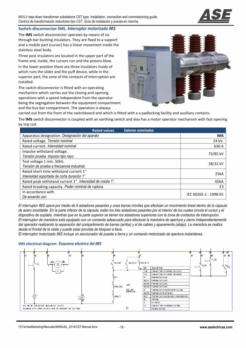
Switch-disconnector IMS. Interruptor motorizado IMS
The IMS switch disconnector operates by means of six
through-bar bushing insulators. They are fixed to a support
and a mobile part (cursor) has a linear movement inside the
stainless steel body.
Three post insulators are located in the upper part of the
frame and, inside, the cursors run and the pistons blow.
In the lower position there are three insulators inside of
which runs the slider and the puff device, while in the
superior part, the zone of the contacts of interruption are
installed.
The switch-disconnector is fitted with an operating
mechanism which carries out the closing and opening
operations with a speed independent from the operator
being the segregation between the equipment compartment
and the bus-bar compartment. The operation is always
carried out from the front of the switchboard and which is fitted with a a padlocking facility and auxiliary contacts.
The IMS switch disconnector is coupled with an earthing switch and also has a motor operator mechanism with fast opening
by trip coil.
El interruptor IMS opera por medio de 6 aisladores pasantes y unas barras móviles que efectúan un movimiento lineal dentro de la cápsula de acero inoxidable. En la parte inferior de la cápsula, están los tres aisladores pasantes por el interior de los cuales circula el cursor y el dispositivo de soplado, mientras que en la parte superior se tienen los aisladores superiores con la zona de contactos de interrupción. El interruptor de maniobra está equipado con un comando adeacuado para efecturar la maniobra de apertura y cierre independientemente del operador realizando la separación del compartimento de barras (arriba) y el de cables y aparamenta (abajo). La maniobra se realiza desde el frontal de la celda y puede estar provista de bloqueo a llave. El interruptor motorizado IMS incluye un seccionador de puesta a tierra y un comando motorizado de apertura instantánea.
IMS electrical diagram Esquema eléctrico del IMS
Rated values Valores nominales
Apparatus designation. Designación del aparato IMS
Rated voltage. Tensión nominal 24 kV.
Rated current. Intensidad nominal 630 A
Impulse withstand voltage.
Tensión prueba impulso tipo rayo 75/85 kV
Test voltage 1 min. 50Hz.
Tensión de prueba a frecuencia industrial. 28/32 kV
Rated short time withstand current 1''
Intensidad soportada de corta duración 1”. 25kA
Rated peak withstand current 1". Intensidad de cresta 1”. 65kA
Rated breaking capacity. Poder nominal de ruptura. E3
In accordance with.
De acuerdo con IEC 60265-1 : 1998-01

MV/LV step-down transformer substations CST type. Installation, connection and commissioning guide.
Centros de transformación reductores tipo CST. Guía de instalación y puesta en marcha.
\\S1\e\AseMarketing\Manuales\MANUAL_2014\CST-Manual.docx - 13 - www.aselectricas.com
Motorized operation Maniobra motorizada
The motorized operation is very easy. You only have to push the opening and the
closing buttons to carry out the operations needed. Likewise is possible to carry out
these operations by means of the telecontrol equipment.
La maniobra motorizada es muy sencilla. Solamente es necesario accionar los pulsadores de apertura y cierre para llevar a cabo la maniobra necesaria. Igualmente es posible realizar estas maniobras por medio del equipamiento de telemando.
Manual operation sequence Secuencia de maniobra manual
Putting in service Puesta en servicio
Close the door removing the
mechanical interlock that
doesn’t allow the earthing switch
operation. Insert the level into
the earthing switch socket and
rotate clockwise.
Cerrar la puerta adecuadamente y abrir el seccionador de puesta a tierra girando la palanca en sentido de las agujas del reloj.
After this operation the signal
disc will assume the suitable
position and the switch-
disconnector socket will be free
by the mechanical lock.
Después de esta operación el disco indicador asumirá la posición adecuada y el socket para maniobra del interruptor quedará libre.
Insert the lever into the switch-
disconnector socket and rotate
clockwise.
Insertar la manivela en el socket del interruptor y girar en sentido de las agujas del reloj.
After this operation the
mechanical lock won’t allow
inserting the level into the
earthing switch socket and the
signal disc will assume the
suitable position.
Después de ejecutar esta operación el seccionador de puesta a tierra queda bloqueado y el disco indicardor asume la posición adecuada..
Putting out of service Poner fuera de servicio
Insert the lever into the swich-
disconnector socket and rotate
counter clockwise.
Insertar la manivela en el socket del interruptor y girar en sentido contrario a las agujas del reloj.
After this operation the signal
disc will assume the suitable
position and the earthing
switch socket will be free by
the mechanical lock.
Después de esta operación el disco indicador asumirá la posición adecuada y el socket para maniobra del seccionador de tierra quedará libre.
Insert the lever into the
earthing switch socket and
rotate counter clockwise.
After this operation the
mechanical lock won’t allow to
operate with the switch-
disconnector socket.
Insertar la manivela en el socket del seccionador de tierra y girar en sentido contrario a las agujas del reloj.
The signal disc will assume the
suitable position and at this
point, you will be able to open
the door.
El disco asumirá la posición correspondiente y en este punto es posible ya abrir la puerta inferior.

MV/LV step-down transformer substations CST type. Installation, connection and commissioning guide.
Centros de transformación reductores tipo CST. Guía de instalación y puesta en marcha.
\\S1\e\AseMarketing\Manuales\MANUAL_2014\CST-Manual.docx - 14 - www.aselectricas.com
Protection relay Relé de protección
SenX is a microprocessor-based overcurrent relay designed for the following applications:
• Main Protection for Medium and Low voltage feeders.
• Main Protection for Medium and Low power Transformers (less than 400kVA).
• Protection functions (ANSI): 50, 51, 27 & 59.
El SenX es un relé de protección de sobre intensidad basado en microprocesador para las siguientes aplicaciones: • Protección principal para alimentadores de media y baja tensión. • Protección principal para transformadores de mediana o baja potencia (menos de 400kVA). • Funciones de protección (ANSI): 50, 51, 27 & 59.
Keyboard Teclado
The front panel of the SenX shows the display, keyboard and status LEDS.
El panel frontal del SenX se compone de un display, teclado y LEDS de estado.
Pushing down arrow key you’ll move along decimal, units and tens. Pushing this key more than two seconds in the
relevant menu, you can erase LED alarms.
Pulsando flecha abajo es posible moverse a lo largo de decimales, unidades y decenas. Pulsando esta tecla más de dos segundos, permite borrar las alarmas de los LED.
Pushing up arrow key you’ll increase the value of the selected figure. If we reached the end, the cycle begins again.
Con la flecha arriba es possible incrementar el valor de la cifra seleccionada. Si se alcanza este extreme, el ciclo comienza de nuevo.
With this key you can access the menus and also you can increase or decrease the values. Also, you have to use this
key to confirm the new settings.
Con esta tecla es possible accede a menús y ajustar valores. Con esta tecla es también posible confirmar nuevos ajustes.
This key is used to exit the current menu without save changes. Se usará esta tecla para salir del menú actual sin salvar cambios.
Leds
LED ON: The relay is energized. El relé está energizado.
LED TRIP: A trip has occurred. (functions 50 or 51). Ha ocurrido un disparo (funciones 50 ó 51) LEDd I >: An overcurrent trip has occurred (function 51). Disparo por sobrecarga ( función 51) LED I >>: A shortcircuit trip has occurred (function 50). Disparo por cortocircuito ( función 50) LED U ><: Over-voltage or under-voltage (functions 27/59). Sobretensión o subtensión ( funciones 27/59) LED HEALTHY: Shows that the software is running. Muestra si el software está corriendo adecuadamente.
Output relays configuration Configuración de los relés de salida.
Relé 4
Relé 3
Relé 2
Relé 1
I> tI>
tI>>I>>
ItI
IIr
I> tI>
tI>>I>>
U<-%Un
tU<-%Un
U>+%Un
tU>+%Un
V
VVs
Vr
Vt
MV/LV step-down transformer substations CST type. Installation, connection and commissioning guide.
Centros de transformación reductores tipo CST. Guía de instalación y puesta en marcha.
\\S1\e\AseMarketing\Manuales\MANUAL_2014\CST-Manual.docx - 15 - www.aselectricas.com
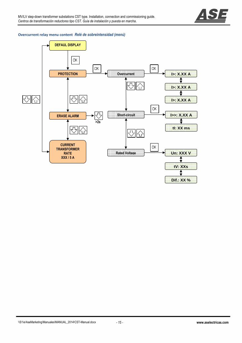
Overcurrent relay menu content Relé de sobreintensidad (menú)
DEFAUL DISPLAY
PROTECTION Overcurrent
CURRENT TRANSFORMER
RATE XXX / 5 A
ERASE ALARM Short-circuit
Rated Voltage
>2s
Un: XXX V
tV: XXs
Dif.: XX %
I>>: X,XX A
tI: XX ms
I>: X,XX A
I>: X,XX A
I>: X,XX A

MV/LV step-down transformer substations CST type. Installation, connection and commissioning guide.
Centros de transformación reductores tipo CST. Guía de instalación y puesta en marcha.
\\S1\e\AseMarketing\Manuales\MANUAL_2014\CST-Manual.docx - 16 - www.aselectricas.com
3. ITE071 Feeder switchboard Celda de línea
Legend Leyenda
1 Control cabinet. Compartimento de control 2 Digital multimeter. Multímetro digital (telemedida).
3 Position indicator for switch-disconnector.
Indicador de posición para interruptor principal
4 Position indicator for earthing-switch.
Indicador de posición para el seccionador de tierra
5 Manual operation switch-disconnector socket.
Socket para operación manual del interruptor
6 Manual operation earthing-switch socket.
Socket para operación manual del seccionador de tierra
7 Instruction plate. Placa de instrucciones
8 IMS motorized switch-disconnector. Interruptor motorizado IMS.
9 Motorized opening push-button. Pulsador de apertura motorizada. 10 Motorized closing push-button. Pulsador de cierre motorizado.
11 Cable box door. Puerta compartimento de cables.
12 Door handle. Maneta de apertura.
13 MV Bridges. Puentes de M.T.
14 Voltage transformer. Transformador de tensión.
15 Field cables entry. Entrada de los cables de campo.
16 Connection point of the field cables.
Punto de conexión de los cables de campo
Dimensions
(W=375 mm, H=1970 mm, D=870 mm)
Weight (207 Kg).
(Ancho=375 mm, Alto=1970 mm, Prof.=870 mm) Peso: 207Kg.

MV/LV step-down transformer substations CST type. Installation, connection and commissioning guide.
Centros de transformación reductores tipo CST. Guía de instalación y puesta en marcha.
\\S1\e\AseMarketing\Manuales\MANUAL_2014\CST-Manual.docx - 17 - www.aselectricas.com
Functional diagram Diagrama funcional
Main busbar Barras generales
Medium voltage motorized switch-
disconnector Interruptor motorizado de media tensión
Voltage transformers
Transformadores de tensión
Connection field cables
Conexión de los cables de campo
Please refer to the diagrams delivered with the equipment.
Por favor, observar los esquemas suministrados con el equipo.
MV/LV step-down transformer substations CST type. Installation, connection and commissioning guide.
Centros de transformación reductores tipo CST. Guía de instalación y puesta en marcha.
\\S1\e\AseMarketing\Manuales\MANUAL_2014\CST-Manual.docx - 18 - www.aselectricas.com
Switch-disconnector IMS. Interruptor motorizado IMS
The IMS switch disconnector operates by means of six
through-bar bushing insulators. They are fixed to a support
and a mobile part (cursor) has a linear movement inside the
stainless steel body.
Three post insulators are located in the upper part of the
frame and, inside, the cursors run and the pistons blow.
In the lower position there are three insulators inside of
which runs the slider and the puff device, while in the
superior part, the zone of the contacts of interruption are
installed.
The switch-disconnector is fitted with an operating
mechanism which carries out the closing and opening
operations with a speed independent from the operator
being the segregation between the equipment compartment
and the bus-bar compartment. The operation is always
carried out from the front of the switchboard and which is fitted with a a padlocking facility and auxiliary contacts.
The IMS switch disconnector is coupled with an earthing switch and also has a motor operator mechanism with fast opening
by trip coil.
El interruptor IMS opera por medio de 6 aisladores pasantes y unas barras móviles que efectúan un movimiento lineal dentro de la cápsula de acero inoxidable. En la parte inferior de la cápsula, están los tres aisladores pasantes por el interior de los cuales circula el cursor y el dispositivo de soplado, mientras que en la parte superior se tienen los aisladores superiores con la zona de contactos de interrupción. El interruptor de maniobra está equipado con un comando adeacuado para efecturar la maniobra de apertura y cierre independientemente del operador realizando la separación del compartimento de barras (arriba) y el de cables y aparamenta (abajo). La maniobra se realiza desde el frontal de la celda y puede estar provista de bloqueo a llave. El interruptor motorizado IMS incluye un seccionador de puesta a tierra y un comando motorizado de apertura instantánea.
IMS electrical diagram Esquema eléctrico del IMS
Rated values Valores nominales
Apparatus designation. Designación del aparato IMS
Rated voltage. Tensión nominal 24 kV.
Rated current. Intensidad nominal 630 A
Impulse withstand voltage.
Tensión prueba impulso tipo rayo 75/85 kV
Test voltage 1 min. 50Hz.
Tensión de prueba a frecuencia industrial. 28/32 kV
Rated short time withstand current 1''
Intensidad soportada de corta duración 1”. 25kA
Rated peak withstand current 1". Intensidad de cresta 1”. 65kA
Rated breaking capacity. Poder nominal de ruptura. E3
In accordance with.
De acuerdo con IEC 60265-1 : 1998-01

MV/LV step-down transformer substations CST type. Installation, connection and commissioning guide.
Centros de transformación reductores tipo CST. Guía de instalación y puesta en marcha.
\\S1\e\AseMarketing\Manuales\MANUAL_2014\CST-Manual.docx - 19 - www.aselectricas.com
Motorized operation Maniobra motorizada
The motorized operation is very easy. You only have to push the opening and the
closing buttons to carry out the operations needed. Likewise is possible to carry out
these operations by means of the telecontrol equipment.
La maniobra motorizada es muy sencilla. Solamente es necesario accionar los pulsadores de apertura y cierre para llevar a cabo la maniobra necesaria. Igualmente es posible realizar estas maniobras por medio del equipamiento de telemando
Manual operation sequence Secuencia de maniobra manual
Putting in service Puesta en servicio
Close the door removing the
mechanical interlock that
doesn’t allow the earthing switch
operation. Insert the level into
the earthing switch socket and
rotate clockwise.
Cerrar la puerta adecuadamente y abrir el seccionador de puesta a tierra girando la palanca en sentido de las agujas del reloj.
After this operation the signal
disc will assume the suitable
position and the switch-
disconnector socket will be free
by the mechanical lock.
Después de esta operación el disco indicador asumirá la posición adecuada y el socket para maniobra del interruptor quedará libre.
Insert the lever into the switch-
disconnector socket and rotate
clockwise.
Insertar la manivela en el socket del interruptor y girar en sentido de las agujas del reloj.
After this operation the
mechanical lock won’t allow
inserting the level into the
earthing switch socket and the
signal disc will assume the
suitable position.
Después de ejecutar esta operación el seccionador de puesta a tierra queda bloqueado y el disco indicardor asume la posición adecuada.
Putting out of service Poner fuera de servicio
Insert the lever into the swich-
disconnector socket and rotate
counter clockwise.
Insertar la manivela en el socket del interruptor y girar en sentido contrario a las agujas del reloj.
After this operation the signal
disc will assume the suitable
position and the earthing
switch socket will be free by
the mechanical lock.
Después de esta operación el disco indicador asumirá la posición adecuada y el socket para maniobra del seccionador de tierra quedará libre.
Insert the lever into the
earthing switch socket and
rotate counter clockwise. After
this operation the mechanical
lock won’t allow to operate
with the switch-disconnector
socket.
Insertar la manivela en el socket del seccionador de tierra y girar en sentido contrario a las agujas del reloj.
The signal disc will assume the
suitable position and at this
point, you will be able to open
the door.
El disco asumirá la posición correspondiente y en este punto es posible ya abrir la puerta inferior.

MV/LV step-down transformer substations CST type. Installation, connection and commissioning guide.
Centros de transformación reductores tipo CST. Guía de instalación y puesta en marcha.
\\S1\e\AseMarketing\Manuales\MANUAL_2014\CST-Manual.docx - 20 - www.aselectricas.com
4. ITE 070 Feeder switchboard Celda de línea
Legend Leyenda 1 Control cabinet. Compartimento de control 2 Digital multimeter. Multímetro digital (telemedida).
3 Position indicator for switch-disconnector.
Indicador de posición para interruptor principal
4 Position indicator for earthing-switch.
Indicador de posición para el seccionador de tierra
5 Manual operation switch-disconnector socket.
Socket para operación manual del interruptor
6 Manual operation earthing-switch socket.
Socket para operación manual del seccionador de tierra
7 Instruction plate. Placa de instrucciones
8 IMS motorized switch-disconnector. Interruptor motorizado IMS.
9 Motorized opening push-button. Pulsador de apertura motorizada. 10 Motorized closing push-button. Pulsador de cierre motorizado.
11 Cable box door. Puerta compartimento de cables.
12 Door handle. Maneta de apertura.
13 MV Bridges. Puentes de M.T.
14 Voltage transformer. Transformador de tensión.
15 Field cables entry. Entrada de los cables de campo.
16 Connection point of the field cables.
Punto de conexión de los cables de campo
Dimensions Dimensiones (W=375 mm, H=1970 mm, D=870 mm)
Weight (235 Kg).
(Ancho=375 mm, Alto=1970 mm, Prof.=870 mm) Peso: 235Kg.

MV/LV step-down transformer substations CST type. Installation, connection and commissioning guide.
Centros de transformación reductores tipo CST. Guía de instalación y puesta en marcha.
\\S1\e\AseMarketing\Manuales\MANUAL_2014\CST-Manual.docx - 21 - www.aselectricas.com
Functional diagram Diagrama funcional
Main busbar with voltage
transformers. Barras generales con trafos de tensión
Medium voltage motorized switch-
disconnector Interruptor motorizado de media tensión
Voltage transformers
Transformadores de tensión
Connection field cables
Conexión de los cables de campo
Please refer to the diagrams delivered with the equipment.
Por favor, observar los esquemas suministrados con el equipo.

MV/LV step-down transformer substations CST type. Installation, connection and commissioning guide.
Centros de transformación reductores tipo CST. Guía de instalación y puesta en marcha.
\\S1\e\AseMarketing\Manuales\MANUAL_2014\CST-Manual.docx - 22 - www.aselectricas.com
Switch-disconnector IMS
The IMS switch disconnector operates by means of six
through-bar bushing insulators. They are fixed to a support
and a mobile part (cursor) has a linear movement inside the
stainless steel body.
Three post insulators are located in the upper part of the
frame and, inside, the cursors run and the pistons blow.
In the lower position there are three insulators inside of
which runs the slider and the puff device, while in the
superior part, the zone of the contacts of interruption are
installed.
The switch-disconnector is fitted with an operating
mechanism which carries out the closing and opening
operations with a speed independent from the operator
being the segregation between the equipment compartment
and the bus-bar compartment. The operation is always
carried out from the front of the switchboard and which is fitted with a a padlocking facility and auxiliary contacts.
The IMS switch disconnector is coupled with an earthing switch and also has a motor operator mechanism with fast opening
by trip coil.
El interruptor IMS opera por medio de 6 aisladores pasantes y unas barras móviles que efectúan un movimiento lineal dentro de la cápsula de acero inoxidable. En la parte inferior de la cápsula, están los tres aisladores pasantes por el interior de los cuales circula el cursor y el dispositivo de soplado, mientras que en la parte superior se tienen los aisladores superiores con la zona de contactos de interrupción. El interruptor de maniobra está equipado con un comando adeacuado para efecturar la maniobra de apertura y cierre independientemente del operador realizando la separación del compartimento de barras (arriba) y el de cables y aparamenta (abajo). La maniobra se realiza desde el frontal de la celda y puede estar provista de bloqueo a llave. El interruptor motorizado IMS incluye un seccionador de puesta a tierra y un comando motorizado de apertura instantánea.
IMS electrical diagram Esquema eléctrico del IMS
Rated values Valores nominales
Apparatus designation. Designación del aparato IMS
Rated voltage. Tensión nominal 24 kV.
Rated current. Intensidad nominal 630 A
Impulse withstand voltage.
Tensión prueba impulso tipo rayo 75/85 kV
Test voltage 1 min. 50Hz.
Tensión de prueba a frecuencia industrial. 28/32 kV
Rated short time withstand current 1''
Intensidad soportada de corta duración 1”. 25kA
Rated peak withstand current 1". Intensidad de cresta 1”. 65kA
Rated breaking capacity. Poder nominal de ruptura. E3
In accordance with.
De acuerdo con IEC 60265-1 : 1998-01
MV/LV step-down transformer substations CST type. Installation, connection and commissioning guide.
Centros de transformación reductores tipo CST. Guía de instalación y puesta en marcha.
\\S1\e\AseMarketing\Manuales\MANUAL_2014\CST-Manual.docx - 23 - www.aselectricas.com
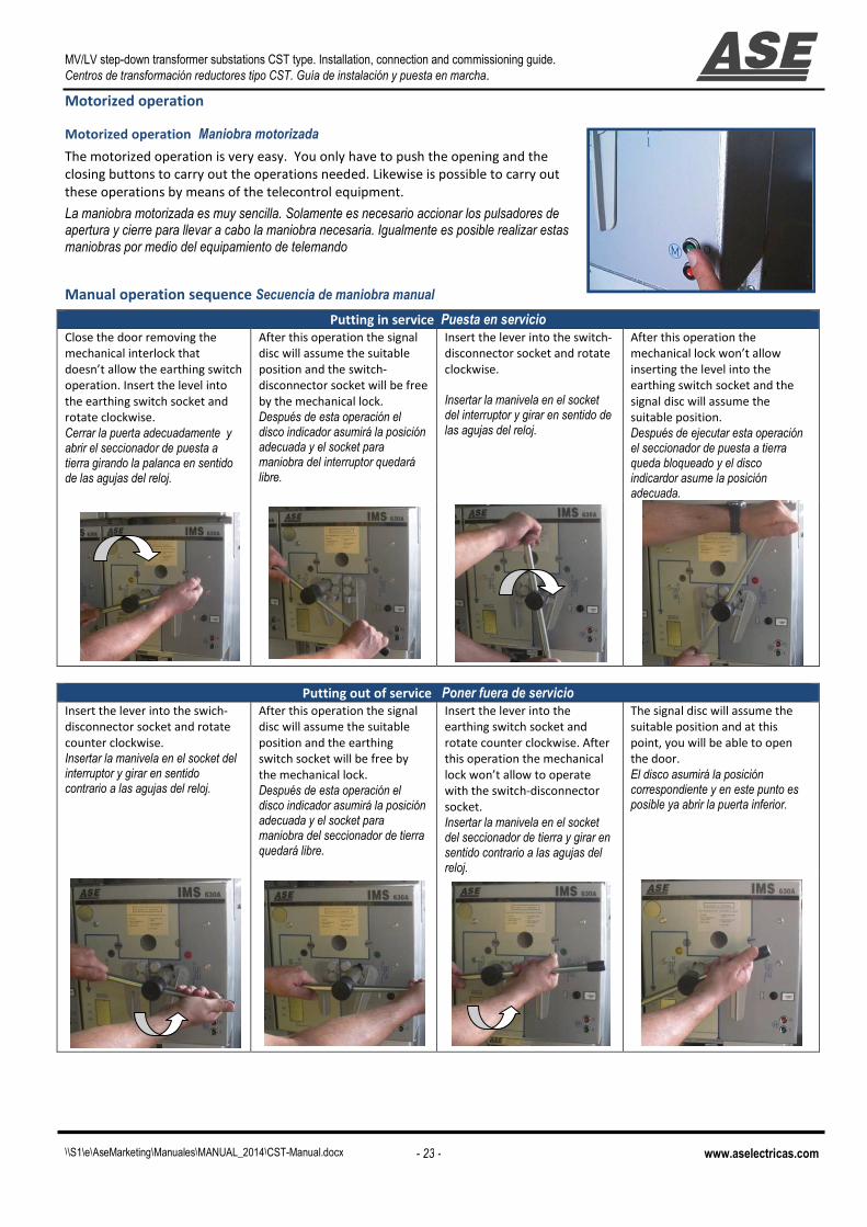
Motorized operation
Motorized operation Maniobra motorizada
The motorized operation is very easy. You only have to push the opening and the
closing buttons to carry out the operations needed. Likewise is possible to carry out
these operations by means of the telecontrol equipment.
La maniobra motorizada es muy sencilla. Solamente es necesario accionar los pulsadores de apertura y cierre para llevar a cabo la maniobra necesaria. Igualmente es posible realizar estas maniobras por medio del equipamiento de telemando
Manual operation sequence Secuencia de maniobra manual
Putting in service Puesta en servicio
Close the door removing the
mechanical interlock that
doesn’t allow the earthing switch
operation. Insert the level into
the earthing switch socket and
rotate clockwise.
Cerrar la puerta adecuadamente y abrir el seccionador de puesta a tierra girando la palanca en sentido de las agujas del reloj.
After this operation the signal
disc will assume the suitable
position and the switch-
disconnector socket will be free
by the mechanical lock.
Después de esta operación el disco indicador asumirá la posición adecuada y el socket para maniobra del interruptor quedará libre.
Insert the lever into the switch-
disconnector socket and rotate
clockwise.
Insertar la manivela en el socket del interruptor y girar en sentido de las agujas del reloj.
After this operation the
mechanical lock won’t allow
inserting the level into the
earthing switch socket and the
signal disc will assume the
suitable position.
Después de ejecutar esta operación el seccionador de puesta a tierra queda bloqueado y el disco indicardor asume la posición adecuada.
Putting out of service Poner fuera de servicio
Insert the lever into the swich-
disconnector socket and rotate
counter clockwise.
Insertar la manivela en el socket del interruptor y girar en sentido contrario a las agujas del reloj.
After this operation the signal
disc will assume the suitable
position and the earthing
switch socket will be free by
the mechanical lock.
Después de esta operación el disco indicador asumirá la posición adecuada y el socket para maniobra del seccionador de tierra quedará libre.
Insert the lever into the
earthing switch socket and
rotate counter clockwise. After
this operation the mechanical
lock won’t allow to operate
with the switch-disconnector
socket.
Insertar la manivela en el socket del seccionador de tierra y girar en sentido contrario a las agujas del reloj.
The signal disc will assume the
suitable position and at this
point, you will be able to open
the door.
El disco asumirá la posición correspondiente y en este punto es posible ya abrir la puerta inferior.

MV/LV step-down transformer substations CST type. Installation, connection and commissioning guide.
Centros de transformación reductores tipo CST. Guía de instalación y puesta en marcha.
\\S1\e\AseMarketing\Manuales\MANUAL_2014\CST-Manual.docx - 24 - www.aselectricas.com

MV/LV step-down transformer substations CST type. Installation, connection and commissioning guide.
Centros de transformación reductores tipo CST. Guía de instalación y puesta en marcha.
\\S1\e\AseMarketing\Manuales\MANUAL_2014\CST-Manual.docx - 25 - www.aselectricas.com
Chapter 2. Installation Capítulo 2 Instalación

MV/LV step-down transformer substations CST type. Installation, connection and commissioning guide.
Centros de transformación reductores tipo CST. Guía de instalación y puesta en marcha.
\\S1\e\AseMarketing\Manuales\MANUAL_2014\CST-Manual.docx - 26 - www.aselectricas.com
1. Workflow Flujo de trabajo
INSTALLATION Placement
Placement and connection of the power
transformer
PRE-COMMISSIONING
Carry out external
electrical connections
COMMISIONING
Interlocks
Checks before
commissioning
Control supply voltage
HV power supply
LV power supply
WORKFLOW
UNPACKING AND HANDLING Unpack the equipment
Check the documents
and supplied material
Carry out internal electrical connection
INSTALACION Colocación
Colocación y conexión del transformador
ANTES DE LA PUESTA EN MARCHA
Realizar las conexiones externas
PUESTA EN MARCHA
Enclavamientos
Comprobaciones antes de la puesta en marcha
Tensión de control
Tensión de potencia AT
Tensión de potencia BT
DESEMPAQ. Y MANEJO Desempaquetar el equipo
Comprobar los documentos y el material
suministrado
Realizar conexiones internas

MV/LV step-down transformer substations CST type. Instal
Centros de transformación reductores tipo CST. Guía de instalación y puesta en marcha
\\S1\e\AseMarketing\Manuales\MANUAL_2014\CST-Manual.docx
2. Handling Manipulación With a forklift (preferred)
When transporting with forklift do not tilt
the equipment. Respect the location of the
Centre of Gravity
With slings
See the illustration.
type. Installation, connection and commissioning guide.
Centros de transformación reductores tipo CST. Guía de instalación y puesta en marcha.
Manual.docx - 27 -
When transporting with forklift do not tilt
the equipment. Respect the location of the
Con carretilla elevadora (recomendado)Cuando el transporte se realice con una carretilla elevadora no inclinar el equipo. Respetar la ubicación del centro de gravedad.
Con eslingas Tal y como muestra el dibujo
www.aselectricas.com
(recomendado) o el transporte se realice con una carretilla elevadora no
inclinar el equipo. Respetar la ubicación del centro de gravedad.
MV/LV step-down transformer substations CST type. Installation, connection and commissioning guide.
Centros de transformación reductores tipo CST. Guía de instalación y puesta en marcha.
\\S1\e\AseMarketing\Manuales\MANUAL_2014\CST-Manual.docx - 28 - www.aselectricas.com
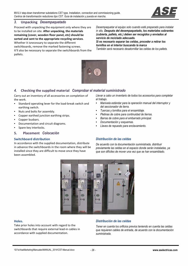
3. Unpacking Desempaquetado Proceed with unpacking the equipment only where they are
to be installed on site. After unpacking, the materials
remaining (cover, wooden floor panel, etc) should be
sorted and sent to the appropriate recycling services.
Whether it isnecessary to separate the different
switchboards, remove the marked fastening screws.
It’ll also be necessary to separate the switchboards from the
pallets.
Desempaquetar el equipo solo cuando esté preparado para instalar in situ. Después del desempaquetado, los materiales sobrantes (cubierta, pallets, etc.) deben ser recogidos y enviados al servicio de reciclado adecuado. Si es necesario separar las celdas, proceder a retirar los tornillos en el interior buscando la marca También será necesario desatornillar las celdas de los pallets.
4. Checking the supplied material Comprobar el material suministrado Carry out an inventory of all accessories on completion of
the work.
• Standard operating lever for the load-break switch and
earthing switch.
• Nuts and bolts for assembly.
• Copper earthed junction earthing strips.
• Copper busbars.
• Documentation and circuit diagrams.
• Spare key interlocks.
Llevar a cabo un inventario de todos los accesorios para completar el trabajo. • Manivela estándar para la operación manual del interruptor y
del seccionador de tierra. • Tuercas y tornillos para el ensamblaje. • Pletinas de cobre para continuidad de tierras. • Barras de cobre para el embarrado principal. • Documentación y esquemas. • Llaves de repuesto para enclavamiento.
5. Placement Colocación
Switchboard distribution
In accordance with the supplied documentation, distribute
in advance the switchboards in the room where they will be
installed since they are difficult to move once they have
been assembled.
Distribución de las celdas
De acuerdo con la documentación suministrada, distribuir previamente las celdas en el espacio donde serán instaladas, ya que son difíciles de mover una vez que se han ensamblado.
Holes.
Take prior holes into account with regard to the
switchboards that require external lead-in cables in
accordance with supplied documentation.
Distribución de las celdas
Tener en cuenta los orificios previos teniendo en cuenta las celdas que requieren cables de entrada, de acuerdo con la documentación suministrada.

MV/LV step-down transformer substations CST type. Installation, connection and commissioning guide.
Centros de transformación reductores tipo CST. Guía de instalación y puesta en marcha.
\\S1\e\AseMarketing\Manuales\MANUAL_2014\CST-Manual.docx - 29 - www.aselectricas.com
Opening of manual switches (only with manual by-
pass switchboard)
Before assembling the MV/LV transformer substation open
the manual switches so that their keys can be extracted
when they are positioned in the safety position in order to
access the lower part of the line switchboards.
Apertura de los interruptores manuales (solo con celda de by-pass manual)
Antes de ensamblar el centro de transformación, abrir los interruptores manuales de tal forma que estos puedan ser colocados en posición de seguridad y las llaves puedan ser extraídas para acceder a la parte inferior de las celdas.
Opening of the transformer cubicle.
Before assembling open the transformer cubicle as follows.
(1)Open LV switch-disconnector.
2)Turn and remove the key.
(3)Insert this key in "KO" (in =T) and then turn.
(4)Close the =T earthing switch and remove key from “KI”
(5)With this key you can open the transformer
compartment.
Apertura del compartimento del transformador Antes de ensamblar el centro de transformación, abrir el compartimento del transformador como sigue: (1)Abrir interruptor de B.T. (2)Girar y extraer la llave. (3)Insertar esta llave en “KO” de =T y girar. (4)Cerrar el seccionador de tierra en =Ty extraer llave de “KI” (5)Con esta llave, acceder al compartimento del trafo.
Assembly steps
Start by assembling the manual by-pass cubicle (if any) and
then L1 and L2 switchboards.
The mechanical assembly of the switchboards must take
place by appropriately using the supplied nuts and bolts to
screw them into the specified holes.
Continue by assembling the remaining switchboards while,
at the same time, installing the general busbar while
ensuring that the busbar voltage transformers are
connected correctly.
Once assembled, install the copper bars for earth
continuity bonding.
Pasos para el ensamblaje
Comenzar ensamblando la celda de by-pass manual (si existe) y posteriormente las celdas L1 y L2. El ensamblaje mecánico de las celdas se lleva a cabo mendiante los tornillos y tuercas suministrados, insertándolos en los agujeros especificados. Se continúa ensamblando el resto de las celdas Mientras que al mismo tiempo, se va instalando el embarrado general, asegurándonos de que los transformadores de tensión de barras se conectan correctamente. Una vez ensamblados, instalar las barras de cobre para la continuidad de las masas.

MV/LV step-down transformer substations CST type. Installation, connection and commissioning guide.
Centros de transformación reductores tipo CST. Guía de instalación y puesta en marcha.
\\S1\e\AseMarketing\Manuales\MANUAL_2014\CST-Manual.docx - 30 - www.aselectricas.com
6. Internal electrical connections Conexiones internas
Routing and connection of the supplied HV cables
Transformer - motorized switchboard connection.
Supplied cables are already connected in the relevant
motorized switchboard (“T” switchboard). They must be
unrolled and inserted through the cable conduits to the
transformer cubicle. The cables must be marked on the
switch and on the cables with R-S (two poles) or R-S-T (three
poles).
Motorized switchboards - Manual by-pass connection.
If the manual by-pass switchboard is included. Supplied
cables are already connected in the relevant motorized
swithboard. They must be unrolled and inserted through the
cable conduits up to the manual bypass cubicle while
connecting them to the lower part of the manual switches.
The cables must be marked on the switch and on the cables
with R-S (two poles) or R-S-T (three poles).
Apertura del compartimento del transformador Conexión entre celda de transformación y celda de protección de trafo. Los cables suministrados están ya conectados en la celda motorizada correspondiente (celda "T").Los cables deben ser desenrollados e insertados a través de los conductos correspondientes. Conexión entre la celda de by-pass manual y las celdas motorizadas. Si se incluye la celda de by-pass manual, los cables de alta tensión ya están conectados en la celda motorizada correspondiente. Estos cables deben ser desenrollados y conducidos a través de los orificios realizados a tal efecto hasta la parte inferior de los interruptores manuales. Los cables deben estar marcados en el interruptor y en las puntas con R-S ó R-S-T.
Control connectors.
On the top part of the transformer cubicle, can be found
the control connection cables to connecting with the other
switchboards. While following the marks on the multi
conductor, connect them using their circular plastic
connectors.
Conectores de control
En la parte superior de la celda de transformación, se pueden encontrar los cables de control para conectar con las otras celdas. Siguiendo las marcas en las mangueras, conectarlas mediante los conectores plásticos.
ALWAYS CHECK THE CORRECT
TIGHTENING OF THE TERMINALS!
¡COMPROBAR SIEMPRE EL
CORRECTO APRIETE DE LOS
TERMINALES!
Pre-installed HV wires. Cables de A.T. pre-instalados

MV/LV step-down transformer substations CST type. Installation, connection and commissioning guide.
Centros de transformación reductores tipo CST. Guía de instalación y puesta en marcha.
\\S1\e\AseMarketing\Manuales\MANUAL_2014\CST-Manual.docx - 31 - www.aselectricas.com
7. Placement and connection of the power transformer. Colocación y conexión del transformador de potencia.
The transformer is the last element that must be
installed in the equipment.
Placement of the transformer.
The transformer has wheels to ensure it is easier to move.
Before the transformer is positioned in its compartment,
the internal front trimming cover must be removed as well
as possibly the earthing junction.
The compartment that houses the transformer has two
metal U-profiles that can be used as a guide for its
positioning.
Transformer connection.
HV cables. The HV cables are connected in the
PROTECTION TRANSFORMER (T) switchboard. Once
inserted through the bushings towards the transformer,
they must be connected to the HV terminals.
LV cables. The supplied low voltage cables must be
connected to the manual fuse switch-disconnector and to
the transformer at the corresponding voltage input: either
230 or 400V.
Klixon temperature switch. Plug the connector for
temperature control.
Earth cable . Connect the existing earthing cable to the
transformer.
El transformador es el último elemento a instalar en el equipo.
Colocación del transformador El transformador tiene ruedas para asegurar un fácil movimiento. Antes de que el transformador sea posicionado en su compartimento, es necesario retirar el embellecedor frontal así como la posible conexión de tierra. El compartimento donde se ubica el transformador tiene dos perfiles metálicos en U que serán usados como guía para su posicionamiento.
Conexión del transformador Cables de Alta Tensión: Los cables de alta tensión están previamente conectados en la CELDA DE PROTECCIÓN DE TRAFO (T) Una vez insertados a través de los pasacables hacia el transformador, deben ser conectados en los terminales de alta tensión del transformador de potencia. Cables de Baja Tensión: Los cables de baja tensión suministrados deben ser conectados con el interruptor manual fusible a la tensión adecuada ya sea 230 o 400 Voltios. Klixon de temperatura: Enchufar el conector del detector de temperatura.. Cable de tierra: Conectar el cable existente de tierra al transformador.
ALWAYS CHECK THE CORRECT
TIGHTENING OF THE TERMINALS!
¡COMPROBAR SIEMPRE EL
CORRECTO APRIETE DE LOS
TERMINALES!

MV/LV step-down transformer substations CST type. Installation, connection and commissioning guide.
Centros de transformación reductores tipo CST. Guía de instalación y puesta en marcha.
\\S1\e\AseMarketing\Manuales\MANUAL_2014\CST-Manual.docx - 32 - www.aselectricas.com
8. External electrical connections. Conexiones externas
Routing and connection of the LV cables.
Connect the low voltage power cables with the appropriate
terminals to the lower part of the manual fuse switch-
disconnector. Next, insert the control and communications
wiring.
Guiado y conexión de los cables de baja tensión
Conectar los cables de potencia baja tensión con los terminales adecuados a la parte inferior del interruptor manual fusible. A continuación insertar los cables de control y comunicaciones.
Connection of the control supply.
Ensure all circuit breakers are open before energizing.
Usually, 110Vdc is used.
Connect the supply cable to the miniature circuit breaker
marked “+ 110 -“. Observe polarity.
Conexionado de la alimentación de control
Asegurarse de que todos los magnetotérmicos están abiertos antes de dar tensión. Normalmente se usa una tensión de control de 110Vdc Conectar el cable de alimentación al magnetotérmico marcado como . “+ 110 -“. Tener en cuenta la polaridad.
Earthing connection.
Connect the building’s grounding network to any earthed
junction of the equipment (1x35 mm2 copper cable is
recommended as minimum).
Conexionado de tierra
Conectar la red de tierras del edificio a cualquier punto de tierra del equipo ( Se recomienda cable de cobre de 1x35mm2 como mínimo).
Remote control connection.
RJ 45 cable must be connected to the connector of the
same type located on the PLC. Route the cable internally.
Conexionado del cable de telemando
El cable RJ45 debe ser conectado al conector del mismo tiempo localizado en el PLC. Guiar el cable internamente.
. LV power cables connection Conexión de los cables de
potencia de baja tensión Connection of the control
supply Conexión de la alimentación de
control.
MV/LV step-down transformer substations CST type. Installation, connection and commissioning guide.
Centros de transformación reductores tipo CST. Guía de instalación y puesta en marcha.
\\S1\e\AseMarketing\Manuales\MANUAL_2014\CST-Manual.docx - 33 - www.aselectricas.com
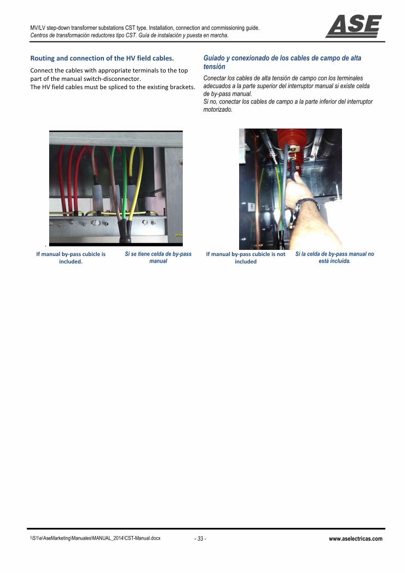
Routing and connection of the HV field cables.
Connect the cables with appropriate terminals to the top
part of the manual switch-disconnector.
The HV field cables must be spliced to the existing brackets.
Guiado y conexionado de los cables de campo de alta tensión
Conectar los cables de alta tensión de campo con los terminales adecuados a la parte superior del interruptor manual si existe celda de by-pass manual. Si no, conectar los cables de campo a la parte inferior del interruptor motorizado.
. If manual by-pass cubicle is
included.
Si se tiene celda de by-pass manual
If manual by-pass cubicle is not
included Si la celda de by-pass manual no
está incluída.

MV/LV step-down transformer substations CST type. Installation, connection and commissioning guide.
Centros de transformación reductores tipo CST. Guía de instalación y puesta en marcha.
\\S1\e\AseMarketing\Manuales\MANUAL_2014\CST-Manual.docx - 34 - www.aselectricas.com

MV/LV step-down transformer substations CST type. Installation, connection and commissioning guide.
Centros de transformación reductores tipo CST. Guía de instalación y puesta en marcha.
\\S1\e\AseMarketing\Manuales\MANUAL_2014\CST-Manual.docx - 35 - www.aselectricas.com
Chapter 3. Pre-commisioning Capítulo 3 Antes de la puesta en
marcha

MV/LV step-down transformer substations CST type. Installation, connection and commissioning guide.
Centros de transformación reductores tipo CST. Guía de instalación y puesta en marcha.
\\S1\e\AseMarketing\Manuales\MANUAL_2014\CST-Manual.docx - 36 - www.aselectricas.com
1. INTERLOCKS Enclavamientos
Standard position of the interlocks. Transformer
interlocks.
Before commissioning, the interlocks must be in their
standard position by following the sequence specified
below:.
Situación normalizada de los enclavamientos. Enclavamientos del transformador
Antes de la puesta en marcha los enclavamientos deben quedar en su situación estándar siguiendo la secuencia especificada a continuación.
Standard position Transformer interlocks Situación normalizada de los enclavamientos del transformador.
(1)Close the transformer
door and remove key.
Cerrar la puerta del transformador y extraer llave..
(2) Insert this key in "KI"
socket of =T and turn.
Insertar esta llave en “KI” de =T y girar.
(3) Open the =T earthing
switch, turn the key in
“KO” socket and remove.
Abrir el seccionador de tierra de =T. Girar la llave en “KO” y extraer.
(4) Insert this key in the
LV switch-disconnector.
Insertar esta llave en el interruptor de Baja Tensión
(5) Close the low voltage
switch- disconnector.
Cerrar el seccionador de Baja Tensión.
Standard position of the interlocks. Feeder switchboards interlocks.
Before commissioning, the interlocks must be in their standard position by following the sequence specified below:
Standard position
Close the lower door
of the relevant
switchboard.
Open the earthing
switch.
Turn the key in the
“KO” socket and
remove.
Insert the key in the
AseC switch
disconnector and turn..
Close theAseC switch
disconnector.
WITHOUT MANUAL BY-PASS CUBICLE
WITH MANUAL BY-PASS CUBICLE

MV/LV step-down transformer substations CST type. Installation, connection and commissioning guide.
Centros de transformación reductores tipo CST. Guía de instalación y puesta en marcha.
\\S1\e\AseMarketing\Manuales\MANUAL_2014\CST-Manual.docx - 37 - www.aselectricas.com
2. Checks before commissioning Comprobaciones antes de la puesta en marcha
Item Item to be checked
Elemento a inspeccionar
1 Placement of the switchboards. Properly aligned
switchboards. Disposición de celdas. Celdas correctamente alineadas.
2 Proper placement of the transformer Colocación adecuada del transformador.
3 Proper connection of the control harnesses. Cables de control (multiconductores) conectados correctamente.
4 Proper voltage in the relevant miniature circuit
breaker. Magnetotérmicos con la tensión de control adecuada.
5 Proper earth continuity bonding Continuidad eléctrica de todas las masas metálicas
6 Check the HV and LV connections of the power
transformer.
Revisar las conexiones de alta tensión y baja tensión del transformador de potencia.
7 Check the connection of the klixon of the power
transformer. Comprobar que el conector del klixon del trafo está conectado.
8 The emergency push-button must be released El pulsador de emergencia debe quedarr liberado

MV/LV step-down transformer substations CST type. Installation, connection and commissioning guide.
Centros de transformación reductores tipo CST. Guía de instalación y puesta en marcha.
\\S1\e\AseMarketing\Manuales\MANUAL_2014\CST-Manual.docx - 38 - www.aselectricas.com

MV/LV step-down transformer substations CST type. Installation, connection and commissioning guide.
Centros de transformación reductores tipo CST. Guía de instalación y puesta en marcha.
\\S1\e\AseMarketing\Manuales\MANUAL_2014\CST-Manual.docx - 39 - www.aselectricas.com
Chapter 4 Commissioning Capítulo 4 Puesta en marcha
MV/LV step-down transformer substations CST type. Installation, connection and commissioning guide.
Centros de transformación reductores tipo CST. Guía de instalación y puesta en marcha.
\\S1\e\AseMarketing\Manuales\MANUAL_2014\CST-Manual.docx - 40 - www.aselectricas.com
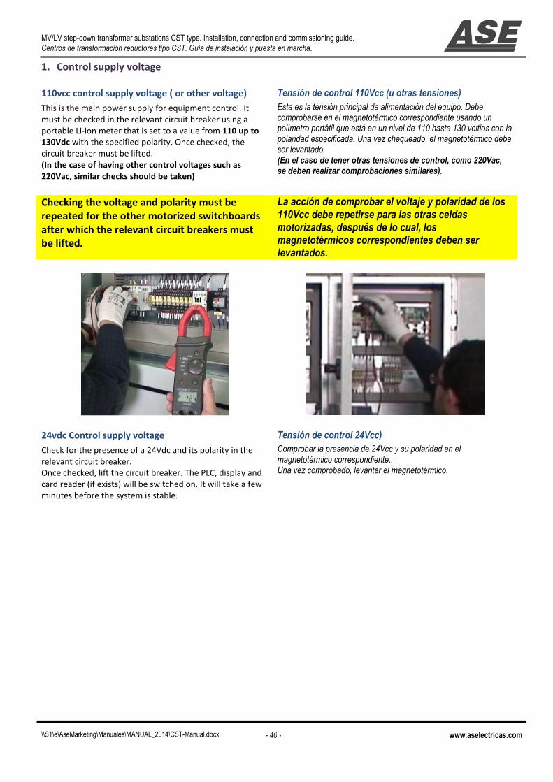
1. Control supply voltage
110vcc control supply voltage ( or other voltage)
This is the main power supply for equipment control. It
must be checked in the relevant circuit breaker using a
portable Li-ion meter that is set to a value from 110 up to
130Vdc with the specified polarity. Once checked, the
circuit breaker must be lifted.
(In the case of having other control voltages such as
220Vac, similar checks should be taken)
Tensión de control 110Vcc (u otras tensiones) Esta es la tensión principal de alimentación del equipo. Debe comprobarse en el magnetotérmico correspondiente usando un polímetro portátil que está en un nivel de 110 hasta 130 voltios con la polaridad especificada. Una vez chequeado, el magnetotérmico debe ser levantado. (En el caso de tener otras tensiones de control, como 220Vac, se deben realizar comprobaciones similares).
Checking the voltage and polarity must be
repeated for the other motorized switchboards
after which the relevant circuit breakers must
be lifted.
La acción de comprobar el voltaje y polaridad de los 110Vcc debe repetirse para las otras celdas motorizadas, después de lo cual, los magnetotérmicos correspondientes deben ser levantados.
24vdc Control supply voltage
Check for the presence of a 24Vdc and its polarity in the
relevant circuit breaker.
Once checked, lift the circuit breaker. The PLC, display and
card reader (if exists) will be switched on. It will take a few
minutes before the system is stable.
Tensión de control 24Vcc) Comprobar la presencia de 24Vcc y su polaridad en el magnetotérmico correspondiente.. Una vez comprobado, levantar el magnetotérmico.

MV/LV step-down transformer substations CST type. Installation, connection and commissioning guide.
Centros de transformación reductores tipo CST. Guía de instalación y puesta en marcha.
\\S1\e\AseMarketing\Manuales\MANUAL_2014\CST-Manual.docx - 41 - www.aselectricas.com
2. Power supply Alimentación de potencia
Energyzing the power transformer (High Voltage
side)
Depending on whether “L1” or “L2” have field energy, we’ll
close one of these in order to energyzing the power
transformer.
Once L1 or L2 is closed, we have to close “T” and the
transformer will be energized.
Energización del transformación de potencia Dependiendo de qué línea tenga energía de campo “L1” o “L2” cerraremos una de ellas.para energizar el transformador de potencia. Una vez cerradas L1 ó L2 debemos cerrar la celda “T” para que el transformador quede energizado.
Low voltage alternate power supply (3x230 or
3x400+neutral)
Close the low-voltage fuse manual switch disconnector in
order to supply the needs of the train control management
system.
Tensión de alimentación en baja tensión Cerrar el interruptor fusible de baja tensión con el fin de alimentar la utilización de B.T. del enclavamiento.

MV/LV step-down transformer substations CST type. Installation, connection and commissioning guide.
Centros de transformación reductores tipo CST. Guía de instalación y puesta en marcha.
\\S1\e\AseMarketing\Manuales\MANUAL_2014\CST-Manual.docx - 42 - www.aselectricas.com

MV/LV step-down transformer substations CST type. Installation, connection and commissioning guide.
Centros de transformación reductores tipo CST. Guía de instalación y puesta en marcha.
\\S1\e\AseMarketing\Manuales\MANUAL_2014\CST-Manual.docx - 43 - www.aselectricas.com
Chapter 5 Annexes
Capítulo 5 Anexos

MV/LV step-down transformer substations CST type. Installation, connection and commissioning guide.
Centros de transformación reductores tipo CST. Guía de instalación y puesta en marcha.
\\S1\e\AseMarketing\Manuales\MANUAL_2014\CST-Manual.docx - 44 - www.aselectricas.com
1. Maintenance Mantenimiento
Levels of maintenance. Niveles de mantenimiento
Description Descripción Levels Niveles
Operations recommended in this manual,
carried out by suitably qualified personnel
having received training allowing them to
intervene whilst respecting the safety rules.
Operaciones recomendadas en este manual,
realizadas por personal cualificado que ha
recibido entrenamiento, que les permita
intervenir respetando las reglas de seguridad.
1
Complex operations, requiring specific expertise
and the implementation of support equipment
in accordance with ASE's procedures. These
must be carried out by ASE or by a specialized
technician trained by ASE when starting the
procedures, with the appropriate specific
equipment.
Operaciones complejas que requieren habilidad especifica y la utilización de equipo adicional de acuerdo a los procedimientos de ASE. Estas operaciones serán realizadas por ASE o por un técnico especializado entrenado por ASE
2
All renovation and reconstruction work is
carried out by ASE.
Cualquier operación de renovación o reconstrucción será realizada por ASE 3
Preventive maintenance Mantenimiento preventivo
Description Descripición Frequency
Frecuencia
Levels
Niveles
Recommended operations Operaciones recomendadas 3 years
3 años 6 years
6 años 1 2 3
Checking of the correct tightening of the
low voltage cables, main busbar, and MV
field cables terminals.
Comprobación del correcto apriete de los terminales de los cables de baja tensión, barras generales y cables de alta tensión.
x x x
Verification of the functioning of the
mechanical control mechanism by making several manoeuvres. Cleaning and
lubrication of mechanical parts.
Verificación del correcto funcionamiento de los mandos motorizados realizando varias maniobras. Limpieza y lubricación de las partes mecánicas.
x x x
Verification of Proper protection I>I>> LV
and MV by Current injection with
adjustable current source.
Verificación del correcto funcionamiento de las protecciones de sobreintensidad en media y baja tensión con una maleta de prueba de relés.
x x x
Visual checking of the proper operation of
voltage indicator lamps and measurement
devices.
Comprobación visual del correcto funcionamiento de las lámparas indicadoras de tensión y de los aparatos de medida.
x x x x
Verification of the presence and condition
of accessories (levers, keys, etc.)
Verificación de la presencia y estado de los accesorios (llaves, manivelas, etc.)
x x x x
Visual inspection of the exterior
(cleanliness, absence of oxidation, etc.)
Comprobación visual del estado de limpieza, ausencia de oxido, etc.
x x x x
Cleaning of external elements, with a
clean, dry cloth.
Limpieza de elementos externos mediante un paño limpio y seco.
x x x x
Verification of the positioning status
indicators (open and closed)
Verificación de los indicadores de posición de aparatos (abierto-cerrado)
x x x
Visual surveillance of the general
appearance of connections.
Inspección visual del estado general de las conexiones.
x x x x
MV/LV step-down transformer substations CST type. Installation, connection and commissioning guide.
Centros de transformación reductores tipo CST. Guía de instalación y puesta en marcha.
\\S1\e\AseMarketing\Manuales\MANUAL_2014\CST-Manual.docx - 45 - www.aselectricas.com
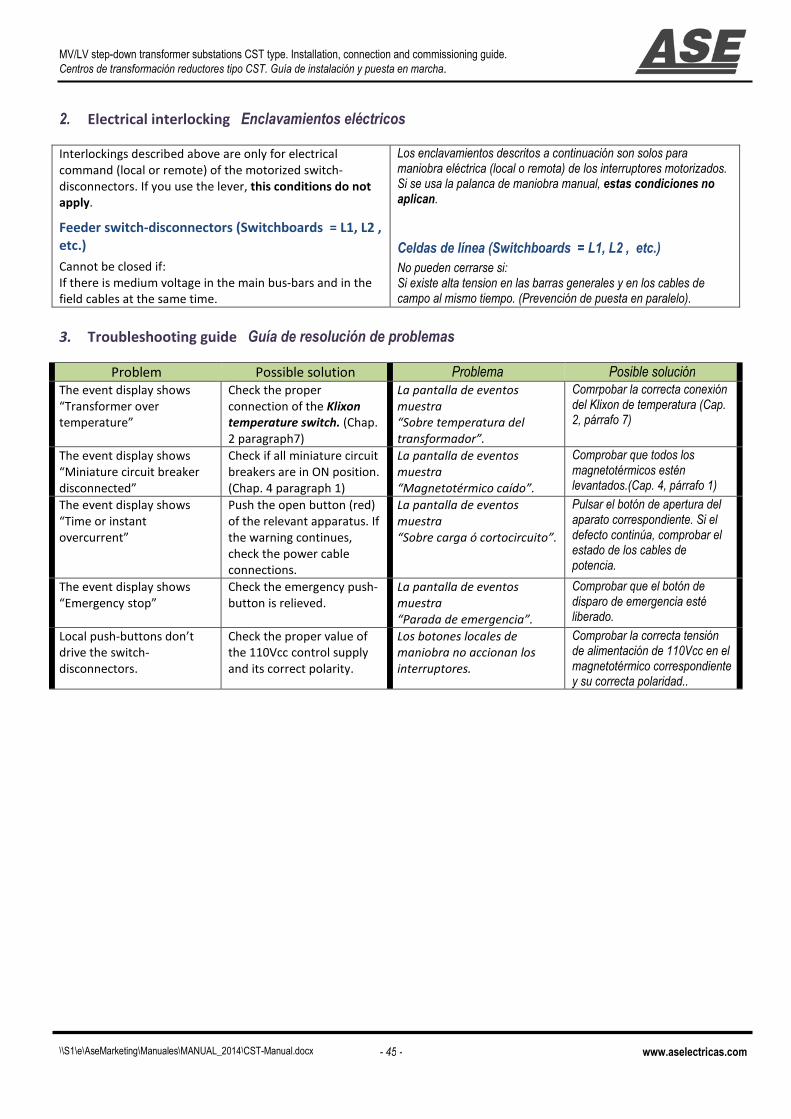
2. Electrical interlocking Enclavamientos eléctricos
Interlockings described above are only for electrical
command (local or remote) of the motorized switch-
disconnectors. If you use the lever, this conditions do not
apply.
Feeder switch-disconnectors (Switchboards = L1, L2 ,
etc.)
Cannot be closed if:
If there is medium voltage in the main bus-bars and in the
field cables at the same time.
Los enclavamientos descritos a continuación son solos para maniobra eléctrica (local o remota) de los interruptores motorizados. Si se usa la palanca de maniobra manual, estas condiciones no aplican.
Celdas de línea (Switchboards = L1, L2 , etc.) No pueden cerrarse si: Si existe alta tension en las barras generales y en los cables de campo al mismo tiempo. (Prevención de puesta en paralelo).
3. Troubleshooting guide Guía de resolución de problemas
Problem Possible solution Problema Posible solución The event display shows
“Transformer over
temperature”
Check the proper
connection of the Klixon
temperature switch. (Chap.
2 paragraph7)
La pantalla de eventos
muestra
“Sobre temperatura del
transformador”.
Comrpobar la correcta conexión del Klixon de temperatura (Cap. 2, párrafo 7)
The event display shows
“Miniature circuit breaker
disconnected”
Check if all miniature circuit
breakers are in ON position.
(Chap. 4 paragraph 1)
La pantalla de eventos
muestra
“Magnetotérmico caído”.
Comprobar que todos los magnetotérmicos estén levantados.(Cap. 4, párrafo 1)
The event display shows
“Time or instant
overcurrent”
Push the open button (red)
of the relevant apparatus. If
the warning continues,
check the power cable
connections.
La pantalla de eventos
muestra
“Sobre carga ó cortocircuito”.
Pulsar el botón de apertura del aparato correspondiente. Si el defecto continúa, comprobar el estado de los cables de potencia.
The event display shows
“Emergency stop”
Check the emergency push-
button is relieved.
La pantalla de eventos
muestra
“Parada de emergencia”.
Comprobar que el botón de disparo de emergencia esté liberado.
Local push-buttons don’t
drive the switch-
disconnectors.
Check the proper value of
the 110Vcc control supply
and its correct polarity.
Los botones locales de
maniobra no accionan los
interruptores.
Comprobar la correcta tensión de alimentación de 110Vcc en el magnetotérmico correspondiente y su correcta polaridad..