
MVi M M VaTT M-Al IM 0 lb mm M MWAN M
26
MVi 91 " M M VaTT M-Al IM 0 lb" mm M ýp W 0 MWAN M 001 Amva,, Pakway PIE /. wAque w Mde= 87 10 Suite 10400 883-6901 July 26, 1988/ O _• .... , .,:. UJNC-ALD-88--119MN Mr. Dale Smith, Director urnu eoeyField Office ay?*~* US Nuclear Regulatory Commissio4, _ 2.: 1 730 Simms Street i , Suite 100 ,..° " Golden, CO 80401 Dear Mr. Smith: •-,/ Enclosed for your consideration is Amendment I to United Nuclear Corporation's (UNC) Tailings Reclamation Plan submitted to NRC on June 1, 1987. The enclosed document amends UNC's proposed reclamation plan to include an active seepage remediation program. It provides a general overview of reclamation activities and a specific implementation schedule for the various work tasks leading to final site remediation. The work as described takes into account the many discussions we have had with NRC and other involved agencies. The amendment contains a description of the active seepage cleanup program UNC proposed on April 27,. 1988. It includes details such as location and number of pumpback wells, anticipated operating conditions, retention/evaporation pond construction details and the attendant construction schedule. UNC continues to believe that its original approach to seepage remediation as contained in its reclamation plan of June 1, 1987. is technically correct and in conformance with regulatory requirements. The active seepage cleanup program described in this amendment is proposed in order to provide additional assurances that any groundwater resources in the area will not be impacted by the tailings facility and to expedite agency approvals. The proposed implementation schedule contained in this submittal is of singular importance as it is integral to the entire program. UNC is committed to implementing the tailings reclamation program described in the document; however, the schedule provided is based• on anticipated approvals forthcoming from all involved agencies by October 1, 1988- Obviously, modification of the reclamation plan as presented and/or delays in receiving approvals will necessarily affect implementation. OFFKA. DOCKET OP' 5$i 10 880726 / A ! t !A \~te an iiQ
Transcript of MVi M M VaTT M-Al IM 0 lb mm M MWAN M

MVi 91 " M M VaTT M-Al IM 0 lb" mm M ýp W 0 MWAN M
001 Amva,, Pakway PIE /. wAque w Mde= 87 10Suite 10400 883-6901
July 26, 1988/ O _• .... , .,:.
UJNC-ALD-88--119MN
Mr. Dale Smith, Directorurnu eoeyField Office ay?*~*
US Nuclear Regulatory Commissio4, _ 2.: 1730 Simms Street i ,Suite 100 ,..° "Golden, CO 80401
Dear Mr. Smith: •-,/
Enclosed for your consideration is Amendment I to UnitedNuclear Corporation's (UNC) Tailings Reclamation Plan submittedto NRC on June 1, 1987. The enclosed document amends UNC'sproposed reclamation plan to include an active seepageremediation program. It provides a general overview ofreclamation activities and a specific implementation schedule forthe various work tasks leading to final site remediation. Thework as described takes into account the many discussions we havehad with NRC and other involved agencies. The amendment containsa description of the active seepage cleanup program UNC proposedon April 27,. 1988. It includes details such as location andnumber of pumpback wells, anticipated operating conditions,retention/evaporation pond construction details and the attendantconstruction schedule.
UNC continues to believe that its original approach toseepage remediation as contained in its reclamation plan of June1, 1987. is technically correct and in conformance with regulatoryrequirements. The active seepage cleanup program described inthis amendment is proposed in order to provide additionalassurances that any groundwater resources in the area will not beimpacted by the tailings facility and to expedite agencyapprovals.
The proposed implementation schedule contained in thissubmittal is of singular importance as it is integral to theentire program. UNC is committed to implementing the tailingsreclamation program described in the document; however, theschedule provided is based• on anticipated approvals forthcomingfrom all involved agencies by October 1, 1988- Obviously,modification of the reclamation plan as presented and/or delaysin receiving approvals will necessarily affect implementation.
OFFKA. DOCKET OP'5$i 10 880726 / A
! t !A \~te an iiQ
UVC-ALO-88- i19MPaqe 2July 26, 1988
Further, while UNC is committed to performance of thereclamation plan, UNC cannot commit expenditures on this projectuntil all involved agencies have concurred that UNC's proposalsatisfies their concerns. You are aware that EPA's Record ofDecision may result in a site remediation ptoposal which differsfrom UNC's proposed reclamation program. Should EPA elect topursue remediation measures which dii.fer from those proposed inthe reclamation plan, UNC's ability to commence performance ofthe reclamation plan may be impaired. This could preclude promptimplementation of reclamation in accordance with the schedule.
Finally, UNC' is aware that NRC technical staff arecontinuing their review of the reclamation plan. We have beeninformed that this review will not be completed until Septemberor October. Technical discussions continue between your staffand ours. It is important that NRC expedite its review of theplan in coordination with the other involved agencies if UNC isto proceed on the schedule presented in the amendment.
UNC strongly believes that the program described in thisamendment is the most suitable program to resolve involved agencyconcerns. It provides additional technical groundwaterprotection measures and is economically feasible. If you haveany questions or require additional information please do nothesitate to contact me.
Sincerely yours,
9\ ,
Juan R. VelasquezManager, Environmental Affairs
J RV: n 1 k
cC: William Rowe EPAMichael Bu-khart - NMEIDHarry Pette•iqill - NRCEdward Hawkins - NRC

I
AmendmentI
Reclamat Ai PlaiLicense No. SUAo!1475
~, (~
II
~1
I¼
95'121801i6 680726PDR ADOCK 04008907C. PDR (Ca I F]'. Hi.
WaSA- -a.. ORWA~2~m

TABLE OF CONTENTS
LIST OF TABLES;
LiST OF FIGURES
LIST OF APPENDICES iii
1.0 INTRODUCTION
1.1 Current Site Conditions 1
1.2 Current Hydrogeologic Condit-ions 2
1,3 Reclamation Plan Objectives 3
2.0 ACTIVE SEEPAGE REMEDIATION AMENDMENT 4
2.1 Seepage Collection System 6
2.2 Well Locations 6
2.2,1 Well Design and Operation 8
2.3 Evaporation Disposal System 9
2.3.1 Evaporation Pond 10
2.3.2 Tailings Mist and Spray Evaporation Systems i0
2.4 Operational Water Balance 12
2.4.1 Inflow 12
2.4.2 Outflow 15
3.0 AMENDED RECLAMATION PLAN OVERVIEW 16
3.1 1988 to 1989 16
3.2 1990 to 1992 18
3.3 1993 to 1997 19
REFERENCES
TABLES
F IGURES
APPENDIX A
. • }'----
11
II.
I,
11
I
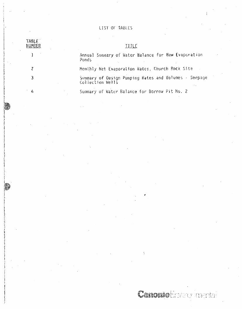
LIST OF TABLES
TABLE
Annual Summary of Water Balance for New EvaporationPonds
2 Monthly Net Evaporation Rates, Church Rock Sirt
3 Summary of Design Pumping Rates and Volumes - SeepageCollection Wells
Summary of Water Balance for Borrow Pit No, 2
~r l~'~ ',s
i i
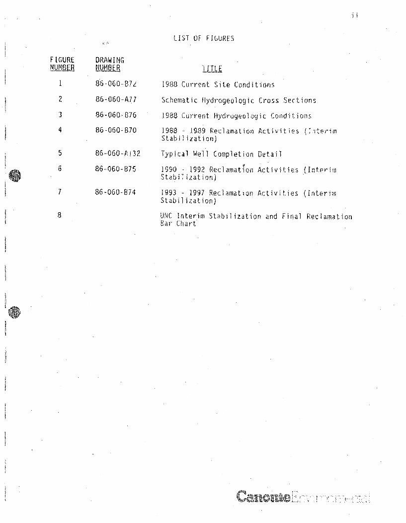
LIST OF FIGURES
F IGURE
1
2
3
4
DRAW ING-NJjL-R86-060-137z
8-060- A77
86-060-8376
86-060-B70
86-0604.ý32
86--060-875
86 0600374
1988 Current Site Conditions
Schematic Hydrogeologic Cross Sections
1988 Current Hydrogeologic Conditions
1988 - 1989 Reclamation Activities ( 1 ,terfimStabilization)
Typical Well Completion Detail
1990 - 1992 Reclamation Activities (InterimStabilization)
1993 1997 Reclamation Activities (InterimStab iizat ion)
UNC Interim Stabilization and Final ReclamationBar Chart
5
6
7
8
A,, ~I' ~

RECLAMATION PLAN AMENDMENT IUNITED) NUCLEIR CORPORATION SOURCE MATERIAL LICENSE SUA-1475
CHURCH ROCK SIVGALLUP, NEW MEXICO
1.0 INTRODUCTION
United Nuclear Corporation (UNC) submitted a Reclamation Plan for the
Church Rock uranium mill and tailings disposal facility near Gallup, New
Mexico, (Canonie Environmental Services Corp. (Canonie), 1987a! on June 1,
1987, UNC is now submitting this document as Amerndment I to the Reucama-tion Plan which provides an overview of the revised reclamation activities
based on comments provided by the Nuclear Regulatory Commission (NRC) andan associated implementation schedule. An active seepage remediation
program is an i tgral part of the amended Reclamation Plan. Details of
the active seepage remediat'in system, including extraction wells, reten-
tion/evaporation ponds, and enhanced evaporative mist systems are provided
herein.
1L.Ltrrmt. Site
Figure I illustrates current site conditions at the Church Rock facil ity.
Sand-like ail-ings were hydraulically disposed within a 100-acre impound-
ment. Sine e mid-1982 when mill operations were terminated, the tailings
have partiily dried, become exposed, and have been blown to the north in
the prevailing wind 6irection. Wind-blown tailings contaminated soils are
found in minor amounts over an area of approximately 50 acres (Canonie.
1987a).
A pit, approximately 45-foot deep, known as Borrow Pit Nc. 2, conserva-
tively estimated to contain about 44 million gallons of water, is located
adjacent to and east of the main body of disposed tailings as shown on
Figure 1. The water originates from three groups. of pumping wells which
extract tailings seepage from the underlying bedrock formations, This
collected water is neutralized and stored in Borrow Pit No. 2.. The water
is disposed of by both natural and an enhanced solar evaporation mist
INN 7"g "m r

system on the surface of the tailings. The system'also serves the function
of controlling the blowing of tailings.
The west side of the tail ings impoundment is bounded by an ephemeral drain-
age channel (Pipeline Arroyo) which will be reconfigured as part of the
reclamation activities (Canonie, 1987a). The mill facilities and the mine
site tailings storage areas located ' the west of the tailings disposal
area will be subject to reclamation efforts.
Prior to mining and milling activities, no contiguous ground water system
was known to exist in the near surface geologic units, including alluvium
and Zone 3 and Zone I of the Gallup Sandstone, in the general area of the
tailings disposal (Canonie, 1987b). It is believed that water was first
introduced to formations underlying the site by the discharge of mine water
into Pipeline Arroyo and later by seepage of tailings liquids from the
tailings impoundment and Borrow Pit No. 2.
Mine water was discharged to Pipeline Arroyo for a period of approximately
17 years during operations. The chemistry of the mine water discharge was
altered as it flowed into the alluvium resulting in. the wate" quality
observed today in the alluvium, Zone 1, and Zone 3 in the areas outside the
influence of tail ings seepage (Canonie, 1987b; Canonie, 1988).
The seepage from the tailings also migrated into the alluvium, as well as
underlying Zone I and-Zone 3 sandstones, as shown schematically on Figure 2
and described in more detail in the Geohydrologic Report (GHR) (Canonie,
1987b). Favorable geochemical properties of the alluvium neutralize the
acidic seepage from the tailings impoundment (Canonie, .1988).
In the northern end of the disposal area, the alluvium was removed for use
in constructing the impoundment's earthen perimetber retention oembankments.
Tailings liquids seeped directly into the underlying Zone 3 sandstone
bedrock formation in this area. Tailings liquids and neutralized seepage
also entered Zone I through the bottom of Borrow Pit No. 2. The
III1V 117 r1<1.1*

geochemi stry of Zone I and Zone 3 1 s not as conducive to neutral ii ng the
acidic seepage as the alluvium, There are two discrete acidic seepagQ
plumes in Zone I and Zone 3. Figure 3 illustrates the approximate extent
of the seepage plumes in Zone 1 and Zone 3 which are described in more
detail in the previous GHR (Canonie, 1987b). Seepage migration has gener-
ally occurred to the northeast in Zone 3 and east in Zone 1 in the direc-
tion of the bedrock dip. The plume is more extensive in Zone 3 than in
Zone I because Zone 3 has a higher permeability than Zone 1. Seepage that
migrated into these formations is currently being collected on a limited
basis by three sets of pumping wells shown on Figure 3. The collectedseepage is neutralized, stored, and evaporated within Borrow Pit No. 2.
A mist evaporation system with a capacity of 350 gallons per minute (gpna)
has been installed on the surface of the central tailings cell to dispose
of water stored in Borrow Pit No. 2. The system operates from mid-April tV
mid-October in accordance with NRC approvals, Figure 3 shows the location
of the mist evaporation system along with the general operations of the
current seepage extraction system.
The objective of the Reclamation Plan, as amended, is to attain long-termstabilization of uranium milling by-product materials solely within the
existing tailings disposal area. The plan will thus control future releas-
es of contaminants to effectively eliminate threats to public health,welfare, and the environment. These objectives will be met by consolidat-ing all by-product materials within the tailings disposal impoundment,
reconfiguring surface water drainage channels adjacent to the site toprevent erosion by flood waters, collecting and evaporating seepage cur-rently within -the underlying bedrock formations, and capping the site toprevent surface water infiltration and radon emissions.
Canona[ y;'i vKt

2.0 ACTIVE SEEPAGE REMEDIATION AMENOMENT
The Reclamation Plan originally submitted (Canonie, 1987a) employed a
passiv;e approach of nMtural contaminant attenuation and dissipation of the
tail ings beepaqp mound to provide the long-teru, protection of human health
and the environment. This amendment to that plan accelerates the attenua-
tion process by incorporating an~active seepage extraction and disposal
system wiv. the reclamation activities described in the original submittal.
While the original approach to seepage remediation remains technically
appropriate, the active approach proposal provides additional assurances
that yround water resources wi 11 not be iwpa.:zted by the tail ings facil i ty,
At Live seepage remediation will consist of the following primary activi-
ties:
o Collection of seepage within Zone 3 of the Gallup S•andstone utilizing
extractin wells.
o Elimination of the source of seepage to Zone I by dewatering Borrow
Pit No. 2.
o Construction of an evaporation dissposal system to include two .syn-
thetically-l ,ned evaporation ponds and associated pond mist system.
o Disposal of the collected seepage from one 3 and water from .o.rowPit No. 2 by evaporationr within the Lailings disposal area.
The design ot this Program for active seepage remediation is ba.- on the
site specific hydrogeologica] and geochemical data (Cananie 1987b; Canonie,
1988)o Conclusions upon which this active seepage remediation program are
based include the following:
o Active remediation of Zone 3 will be performed in areas of acidic
tailings seepage delineated by pH measurements of less than seven,
Since Zone 3 has no acid buff.ring capacity, pH measurements belo

seven are interpreted as the extent of the tail ings Seepage plume in
that formation.
SSeepage in zone 3 emanates from the tilings disposal area to the
6ortheast, This area, shown on figure 3, will be the io:ation of the
ground water extraction wells.
o Seepage in Zone 1 origin•tes from it; outcrop in Borrow Pit No. 2.
Since Borrow Pit No. 2 will be dewatered as part of the reclamatioo
activitieis the source of seepage will be removed. No additional
active remediation wil be required for Zone 1. The permabiiity of
Zone I is so low .that the formation will not support pump ing once the
pit is dry. Wells currently pumping from Zone I adjacent to Borrow
Pit No. Z have already demonstrated this low productivity which pre-
cludes pum ping and extraction of seepage a viable remediation
option in Zone 1 (Canonie, 1987b).
o The remaining North Cross Dike and all the East pump-back wells will
be decommissioned in 1989, when Borrow Pit No. 2 is dewatered.
o Acidic seepage is not present in the alluvium due to the large buff-
aring capacity of the soil (Canonie, 1987b; Canooie, 1988). Aia.ytes
detected in the saturated alluvium are primarily derived from percola-
tion of mine water through the alluvial soils and therefore are con-
sidered "background" concentration levels. Tailings seepage cannot be
identified in the alluvial soils; therefore, no active remediation is
necessary for the alluvium.
The seepage collection system in Zone 3 will utilize both existing wells
and new wells to be installed during the interim stabilization phase of
reclamation. The evaporation disposal system will consist of 1) a two-
pond, ten-acre lined evaporation/surge system equipped with an enhanced
evaporation mist system, and 2) a separate mist or spray evaporation system
instailed on the surface of the tailings. ILhe evaporation disposal system
will be installed and operated entirely within the tailir gs disposal area,

The following sections provide the basis for the selection of the seepage
collection and evaporation disposal systems for active seepage remediation
at the site. Figures 4 through 6 schematically illustrate the major corn-
ponents of the two systems, Details of the components of the lined evapor-.
ation ponds are provided on the drawings contained in Appendix A. Table I
summarizes the water balance upon which oppration of the system is based,
The seepage collection system for Zone 3 was designed based on the follow-
ing hydrologic conditions:
o The extractable volume of the acidic plume in Zone 3 (Figure 3), is
estimated to be 200 million gallons or less, based on an area of the
plume of 100 acres, an observed average saturated thickness of 60
feet, and an extractable porosity of 10 percent. The system was
designed to remove this approximate volume. However, monitoring of
hydrogeologic conditions during operation of the system will determine
the extent of pump.-ing actually required.
o ihe saturated thickness and the extent of the acidic plume., as deline-
ated by the pH seven contour, was used to determine the general loca-
tions of the wells. The actual locations will be finalized in the
field.
o The limited extent of the saturated thickness of Zone 3 and projected
reductions in well efficiencies during remediation control the number,
of wells that can be installed and operate efficiently for periods of
several years or more.
Ftgure 4 shows the approximate locations of 14 new wells that will initial-
ly be utilized for the Zone 3 seepage collection system. Figure 5 il-
lustrates the general construction details for each extraction well. Four
wells in the existing Northeast pump-back system will also continue to
II
~¶1

K7
operate. In 1990, six additional new wells will be installed within and at.
the northern boundary of the acidic plume as shown on Figure 6.
Extraction well locations were selected to pump from the maximum saturated
thickness observed in the formation, as presented on Figures 4 and 6,
thereby effectively intercepting the seepage plume to the east-northeast.
Figure 4 provides an isopach map of saturated thi':kness based on water
levels" measured in Zone 3 wells in October, 1987. The figure shows that
maximum saturated thicknesses of 40 feet to 60 feet in Zone 3 are encount-ered north and northeast of the tailings area, where the majority of the
wells are proposed to be installed. Wells were not located further to the• east because of the small (less than ten feet) saturated thickness of Zone
3 in that area.
The ground water system at the site is transient (Canorie, 1987b). Since
additional recharge from mine water discharge and tail ings disposal sources
has ceased, water levels in Zone 3 will continue to decline in response to
current and future dewatering activities. Therefore, the final location of
each well will be determined immediately prior to its installation based on
the most current water level measurements available.
The proposed spacing of the wells, as shown on Figures 4 and 6, was deter-
K mined by employing an analytical model. (Theis equation) to ensure that:
o The wells will create a hydraulic barrier to further migration of the
acidic plume,
0 The wells will dewater the eastern extremities of the acidic plume
where the small saturated thickness precludes direct placement of
wells.)
0 The intersection of cones of depression from adjacent pumping wellsw il not cauese excessi e interference between wells which wouId impact
the efficiency of the system,

The final spacing of the wells will be adjusted during their installation
based on aquifer tests conducted in the first two or three wells that are
installed.
Figure 5 presents typical well completion details for the new wells to be
installed for the seepage collection system. The wells will be completed
with the screen entirely within and at the base of Zone 3. Each well will
be constructed with six-inch diameter polyvinyl chloride (PVC) casing and
screen.
The wells will be drilled using rotary air/foam methods, if possible.
Alternatively, use of mud-rotaary methods iLy be required. A geophysical.
log of each borehole will be obtained prior to well installation to provide
the data for final adjustments to the design details of the wells.
The wells are predicted to operate at an average initial rate of five gpm
based on pumping records for existing on-site wells and the hydrologic
properties of Zone 3 (Canonie, 1987b). Initial extraction rates may be
higher or loiwer in each well than the five gpm chosen as the best estimate
for design of the system. However, the proposed evaporation disposal
system has the flexibility to accommodate variability in well pumping
rates.
Pumping rates are predicted to decline by approximately 20 percent per year
based on the long-term pumping records for existing on-site wells and
hydrologic properties of Zone 3. The decline in pumping rates will be
caused by the reduction of saturated thickness and the anticipated reduced
efficiencies of the well screens due to precipitates. Some of the new
wells may have to be replaced each year in order to maintain the production
rate of the system.
The number and timing to replace wells will be determined based on system
performance. Once a well begins to lose its ability to pump efficiently it
will be evalua'-d for stimulation to improve productivity or, if its
'- :• ... +•++•."' '+ ++"'+ -. •;.L... )'" +L":l'"i-'%i'+.

productivity declines to or below one gpm for a period of one month, pos-sible roplacement. The well will be stimulated and cleaned, then turned
off and allowed to recover to determine whether the formation can produce
sU fficient water to merit replacetnrit of the well, If the water level
recovers sufficiently to produce one gpm, but the efficiency of the well
does not allow production of one ypm or more, then the well will be
replaced. If the water level in the well does not recover sufficiently to
allow production of water in amounts greater than one gpm, the well will be
decormni ssioned.
The goal of active seepage remediatiurn is, to the extent technically prac-
tical, to remove the acidic seepage from Zone 3. The system will be decom-
missioned upon a determination by UNC in conjunction with the NRC that thehydrogeologic or water quality conditions in Zone 3 are adequate. Based on
the schedule presented in Section 3.0 of this amendment, these conditions
are expected to be met by the end of 1995.
L, _vap1 _ra tn Di S.go s a I eS m s Q
Extracted seepage from the pumping wells will be directed to the evapora-
tion pond and/or mist or spray evaporation systems for disposal. The ev-
aporation disposal system was designed based on both climatic and opera-
tional considerations. Table 1 summarizes the operational considerations,
and Table 2 summarizes the average monthly net evaporation and precipita-
tion rates for the site used for design purposes. This data, in addition
to the anticipated pumping rates for the seepage collection system, were
used to size the ponds and mist and spray systems.
Evaporation will be from the surface of the" ponds, through atomizing mist
nozzles installed in each pond, arid through the mist or spray evaporation
systems installed in the Central Cell of the tailings area.
_1110 il!1 111B
1 0
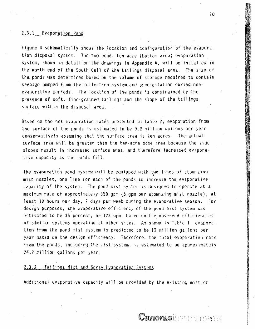
Figure 4 schermatically shows the locatioii and configuration of the evapora-
tion disposal system. The two-pond, ten-acre (bottom area) evaporation
system, shown in detail on the drawings in Appendix A, will be installed in
the north end of the South Cell of the tailings disposal area. The size of
the. ponds was determined based on the volume of storage required to contain
seepage pumped from the collection system and precipitation during non-
evaporative periods.. The location of the ponds is constrained by the
presence of soft, fine-grained tailings and the slope of the tailings
surface within the disposal area.
Based on the net evaporation rates presented ift Table 2, evaporation from
ihe surface of the ponds is estimated to be 9.2 million gallons per year
conservatively assuming that the surface area is ten acres, The actual
surface area will be greater than the ten-aizre base area because the side
slopes result in increased surface area, and therefore increased. evapora-
tive capacity as the ponds fill,
The evaporation pond system will be equipped with two lines of atomizing
mist nozzles, one line for each of the ponds to increase the evaporative
capacity of the system. The pond mist system is designed to operat.e at a
maximum rate of approximately 350 gpm (5 gpm per atomizing mist nozzle), at
least 10 hours per day, 7 days per week during the evaporative season. For
design purposes, the evaporative efficiency of the pond mist system was
estimated to be 35 percent, or 123 gpm, based on the observed efficiencies
of similar systems operating at other sites. As shown in Table 1, evapora-
tion from the pond mist system is predicted to be 15 million gallons per
year based on the design efficiency. Therefore, the total evaporation rate
from the ponds, including the mist system, is estimated to be approximately
24.2 million gallons per year.
2LT .j.is Mist and __SpjE vaporation Svstem
Additional evaporative capacity will be provided by the existing mist or
Pu
I1
future spray evaporation systems located on the tailings surface in the
Central Cell of the tailings disposal area.
JF-•Li•L!1 LL• t Mit 0Mte- m - Currently, a mist evaporation system lo-,
cated in the Central Cell with a capacity of 350 gpm (4.2 gpm per nozzle)
Is being used to evaporate water stored in Borrow Pit No. 2. Figures 3 and
4 and the drawings in Appendix A show the general location and configura-
tior of V-,is system. This system was approved for operation by the NRC and
has been jr;:-ating since mid-April of 1988. The mist system is scheduled
to continue c•e.nating until 1990, when the system will be removed so that
tailings grading ;.% •'-il cover placement for interim stabilization can
commence in that area,
The mist system is currently operatir 12 hou s per day, 5 days per week,
except during precipitation events. At!" water discharged through the
system currently originates from Borrow Pit No. 2. The total volu.me of
water to be discharged through the mist evaporation system in 19PS is
estimated to be 20 million gallons. The system will be shutdown at the end
of the evaporation season in mid-October in accordance witf NRC license
conditions. At that time, all seepage pumped from the existing pump-back
wells will be discharged to Borrow Pit Jio, 2 urtil the evaporation pond is
constructed and operatiornal.
Fjt.ure TaILjinLgs SaralEvaoration _Sy stem - A spray evaporation system will
replace the existing mist evaporation system on the tailings after interim
stabilization grading and cover placement are com•ieted in the Central Cell
of the tailings disposal area. The spray system has been designed so that
there will be no infiltration into the cover soils. The system will con-
sist of a series of spray guns which can each wet an area of approximately
one acre. The guns will be operated sequentially to balance application
rates and evaporation rates. Table 2 presents the evaporation rates for
the site used in the design. The maximum application rates will v•ary
depending on the month and may range up to 5,800 gallons per day, per acre.
The spray system was selected to replace the wist system, for this site,
because of greater flexibility of cperation. The capacity of the spray

12
system Is greater than the anticipated volume of seepage predicted to bedischarged to the system. Therefore, if the volume from the seepage col-
lection system is temporarily greater than anticipated, the spray system
will be able to accommodate the additional volume. Spray guns can also be
added or subtracted from the system to adjust to changes in climartic condi-
tions, such as dry or wet years, or to changes in volumes pumped from the
seepage collection system.
The design of the seepage collection and evaporation disposal systems was
based on a water balance which provides that all seepage collected from
Zone 3, as well as stored seepage in Borrow PiL No. 2, will be evaporatedbetween the years 1988 and 1996. Table I summarizes the water balance of
inflow and outflow for active seepage remediation. The following sections
provide a more detailed discussion of each of the components of inflow and
outflow.
Inflow to the system will consist of 1) seepage pumped from the collection
system, 2) water pumped from Borrow Pit No. 2, and 3) precipitation. The
contribution from each of these components is described below.
YL go.a_.Q llection System- Pumping volumes from the existing wells and tne
new wells vary from year to year depending upon the number of wells operat-
ing and the anticipated decline in pumpir3 rates due to well productivity.[able I presents the total volumes estimated to be pumped each year from
the wells, and Tables 3 and 4 present details of pumping from Zone 3 and
Borrow Pit No. 2.
Pumping volumes from the new wells are based on an expected initial pumping
rate of five gpm per well, The volumes are also based on an expected 20
percent decline in the pumping rate of each well per year. Since 14 wells
will be installed initially and 6 more wells will be added the
I .. ,• i '/ • , '= : a i • 7 ] {'

13
following year, the volumes pumped are also based on the number of wells
that are proposed to operate during a given year.
The volume of seepage to be pumped from Zone 3 is estimated to be 200
million gallons. This volume was estimated from the area of the acidic
plume in Zone 3 as delineated by the pH 7 contour (Canonie, 1987b) ý4,00
acres), an average saturated thickness of Zone 3 of 60 feet determined from
May, 1986 water level data reported in the GHR (Canonie, 1987b), and an
extractable porosity of 10 percent. The porosity of ten percent was se-
lected based on data for pumping tests conducted in on-site Zone 3 veIls.
The pumping test data, (summarized in the GHR), indicate that the average
storativity of Zone 3 is 0.05. Therefore, approximately five percent of
the water contained in the formation can be removed by pumping. For design
purpGses, this percentage of pumpable volume was increased two times tn ten
percent.
The potential for additional recharge to the Zone 3 plume from infiltration
of precipitation was evaluated to determine whOLher the volume of this
potential recharge source wouId change the anticipated volume to be pumped
from Zone. 3. The potential recharge was evaluated using the water balance
mnethod [Environmental Protqction Agency (EPA),.19751. This me thod utilized
mean monthly temperature data. from Gallup, New Mexico, for the years 1951
through 1980, and precipitation data from the Church Rock site for, theyears 1980 through 1986. The results of this analysis showed that percola-
tion through the compacted soil cover as designed will not occur, There-
fore, no resaturation of Zone 3 or remobilization of residual seepage will
take place after capping the tailings area. This conclusion is considered
to be conservative because the analysis assumed'that no runoff occurred and
that all the water from precipitation was available for infiltra tion.
(Backup data are available upon request),
The water balance recharge calculations were confirmed by using the EPA
computer model "The Hydrologic Evaluation of Landfill Performance" (HELP),
(EPA, 1984). As with the water balance method, the HELP model predicted no
percolation of precipitation through the cap. The fact that no percolation
is predicted to occur indicates that the cap material behaves like an

evaporative sponge in this climate, retaining enough water to prevent deep
percolation during rainfall events and also alloring evapotranspiration of
the retained water during dry periods.
The validity of the above conclusions i". verified by site conditions which
existed prior to mining and milling activities. Prior to mining opera-
tions, the infiltration area to Zone 3 was covered by uncompacted alluvium
with a prot:able hydraulic conductivity of 10-3 centimeters per second
(cm/sec) to W04 cm/sec. Even with this transmissive coVw• sEl, site
climatological conditions were such that saturated conditions did not exist
in Zone 3 (Canonie, 1987b). This is empirical evidence that deep infiltra-
tion and recharge will not occur in any signifzant amounts, as a function,
of climate and soil properties, at the Church Rock site.
.Orrow PiLo. 2 - The water stored in Borrow Pit No. 2 is discharged to
the existing mist evaporation system and will be discharged to the evapora-
tion pond when the. system is constructed. As shown in Tabie 4, approxi-
matnIv 0q million gal-lons will be removed fro• the pit by the end of 1988.
, .aume includes puoping from the pit., evaporation from the pit's water
surface, seepage from the pit, and inflow te the pit from the existing
pump-back wells.
In 1989, t he only inflow to the pit is expected to be precipitation and
poss.ible seepaye from the surrounding saturated all uvium and Zoe I. The
dewatered pit will act as a collection well for these formations Th•i S
small quantity of seepage and precipitation will be pumped to the evapora-
tion disposa s v
I hnflow to the evaporation pond from precipitation was
.stimated from the on-site average monthly net evaporation data presentedin Table 2. Total inflow from precipitation is eimated to be 300,000
gallons per year for a 10-acre pond surface area,
C8,Pe

utflow from the system will include evaporation from the surface of the.vaporation ponds, evaporation from the pond mist system, and evaporation
From the mist and spray evaporation systems located on tailings (depending
in which system is in operation). The following provides a description of
each of these components.
S uL fAu•- EvaporaLion from the surface of the ponds was calculated
from thr average monthly net evaporation rates presented in 'Table 2 and a
surface area of ten .acres. Table I shows that the volume of water es-
timated to evaporate from the pond surface each year is 9,2 million gal-
on s.
!(,nLdi3LjtqM - The mist system in the evaporation ponds is designed to
achieve an average evaporation rate of 123 9pm assuming 35 percent ef-
ficikncy., -the estimated maximum volume disposed through the mist system is
K5 million gallons per year.
MiýL...5jt_,j rDj, t_EaJUfp jol n SYM_ - The volume of water discharged through
The mist and spray evaporation systems may vary up to 18 million gallons
per year depending on the evaporation requirements during the time period
in consideration. As shown in Table I, the volumes discharged through the
v'ist and spray evaporation systems decline corresponding to the declining
jischarge rates from the seepage collection system.

3.0 AMENDED RECLAMATION PLAN OVERVIEW
The proposed overall Reclamation Plan for the site can be divided intothree general phases identified as i) interim stabiiization, 2) seepage
collection, and 3) final reclamation cover. The interim stabilization
phase (1988-1992) is designed to mitigt.te existing environmenta F. raceimpacts of past operations, to minimize immediate contaminant exposure
pathways, to minimize future subsurface impacts, and to prepare the site
for installation of the final reclamation cover (1993-1997). Seepage.
collection, occurring during interim stabilization and extending into thefinal reclamation cover periods, is designed to contain and remove to the
extent practical, the seepage plumes in Zone I and Zone 3.
The following paragraphs provide a generalized synopsis of reclamation
activities which will be perforned as part of each of the three phases.Figures 4, 6, and 7 IIlustrate major components of each phase on; an annual
basis for the entire anticipated period of reclamation. The proposed
schedule of each reclamation phase is nrovided on Figure 8 and is based
upon ac:ceptance and approval of the p,r; from all regulatory agencies on or
before September 30, 1988. The schedule for implementing this plan will
correspondingly change if receipt of approvals is delayed.
Figure 4 illustrates reclamation activities which will occur during the
remainder of the 1988 construction season and through 1989. Activities
initiating in 1988 include plugging 41 existing monitoring wells.in the
area of active reclamation to eliminate hydrologic pathways between geoiog-
ic formations and to allow future reclamation activities to progress unim-
peded. The western portion of the North Cross Dike pump-back system will
be decommissioned at the time these wells are plugged. During 1988, theradiological survey submitted with the tailings reclamation plan in 1987
(Canonie, 1987a) will be supplemented to include areas omrtheast of the
tailings irupoundment and off of the UNC property, in Section i, TI6M, R16W,
to ascerivin if wirnd-blown tail ins-affected soils extend beyond UKC's
propery.
. W .. V yr 0]
I/
In preparation for disposal of stored seepage in Borrow Pit No. 2 and
increased volumes of collected seepage, the syntheticalIy-lined evaporation
pond system will be constructed in 1988. An isolated area of tailings in
the north end of the South Cell will first be regraded in preparation for
construction of the pond system within the tailings impoundment, as shown
schematically on Figure 4. Details of the system are illustrated on the
drawings contained in Appendix A. The constructed ponds will have adequate
capacity to store collected seepage during non-evaporative periods of the
year and will also be used to evaporate seepage during the evaporation
season. The ponds will each be equipped with an enhanced evaporation
atomizing mist system to increase their evaporative capacity prior to the
1989 evaporation season. As part of 1988 activities, the existing mist
evaporation system on the tailings surface has been expanded and is being
used to eliminate stored water in Borrow Pit No. 2.
The following year (1989), tailings in the North Cell will be regraded in
preparation for the disposal of wind-blown tailings. Soils affected by
wind-blown tailings to the north and east of the impoundment will be strip-
ped and placed over the regraded tailings in the north end of the tailings
disposal area. At that time, the tailings in the North Cell will be soil-
covered, preventing further dispersion of tailings outside of the impound-
ment by wind.
Borrow Pit No. 2 is expected to be initially dewatered near the end of
1989. This will remove the primary source of seepage into Zone 1. The
existing Zone I pumping wells located adjacent to Borrow Pit No. 2 (East
and remaining North Cross Dike pump-back wells, shown on Figure 3) will be
decommissioned when dewatering of Borrow Pit No. 2 has been completed.
Borrow Pit No. 2 may have to be temporarily used to store water in 1990
when the Central Cell area of tailings is being regraded and the mist
evaporation system is not in operation.
New Zone 3 pumping wells will be installed in 1989, as described in Section
2.0, to inccrease the ground Water extr(ction rate from Zone 3. The new
wells are estimated to operate at an initial average maximum rate of ap-
proximately 5 gpm, decliingng by approximately 20 percent per year. As
V8
shown on Figure 4, these wells will be located approximately within the
boundaries of the acidic plume in Zone 3. Locations of the wells have been
selected to prevent further migration of the contaminant plume and make use
of the maximum available saturated thickness of the formation, Because of
the transient nature of the ground water system, the saturated thickness
and shape of the plume are expected to change with time. Therefore, final
well locations will be determined immediately prior to well installation
based on evaluation of the most current hydrogeologic data.
Figure 6 illustrates those reclamation activities which are proposed to
occur in 1990-1992. Earthwork activities consist of regrading the tailings
in the Central and South Cells of the tailings disposal area. Following
regrading, a one-foot thick soil cover will be placed over the regraded
tailings to prevent further wind dispersion of the tailings from these
areas toward the north.
In 1990, the mist evaporation system will be removed from the central
portion of' the tail ings disposal area to allow tailings regrading and soil
cover placement in that general area, as shown on Figure 6. During soil
covering of the Central Cell and placement of the spray evaporation system,
the water from the seepage collection system will, if necessary, be
directed to Borrow Pit No. 2, as requested by the NRC. Figure 6 also shows
six new Zone 3 pumping wells that are proposed to be installed along the
northern boundary of the acidic plume. These wells will bring the total
number of new wells to 20. The spray evaporation system will be placed
over the soil-covered tailings in the Central Cell area to continue
providing qufficient capacity for evaporation of water from the Zone 3
wells, Water temporarily stored in Borrow Pit No. 2 will be pumped to the
evaporation disposal system when the Cemtral Cell spray system is
operational. Regrading and soil cover placement in the South Cell will
occur in 1991.

The dewatered Borrow Pit No. 2 will provide suitable capacity and flexibil-
ity for the disposal of demolished mill structures in 1992. Although the
objective of the plan is to dewater the pit prior to 1992, the uncertain-
ties associated with seepage pumping rates and evaporation rates require
that mill decommissioning be scheduled in 1992 to assure that the oit will
lbe ready to receive the demolished milling materials.
.LJ12_J9A 1ý_997
Reclamation activities in 1993 will consist of pumping and evaporation of
seepage. Final reclamation cover placement activities will be i;bvtiated in
1994 and will be completed in 1997. As shown on Figure 7, the Zone 3
pumping wells, evaporation pond, and spra, vvstem in the Central tell are
anticipated to operate through 1995 assuming that, as estimated, the seep-
age plume in Zone 3 has been mitigated to the extent practical IKy the end
of 1995. The seepage remediation system will be decommissioned ý,Ten the
Zone 3 formation has been effectively dewatered, as determined b[ the
inability of the pumping wells to further withdraw practical q>. tities of
water.
Final reclamation activities during the period from 1994 through 1997
primarily involve reconfiguring the Pipeline Arroyo channel so that the
channel can contain the Probable Maximum Flood and have miNOirWi impact on
']•,) the reclaimed tai1 ings. Riprap w ill be placed in channel sections suscep-
tible to erosion to maintain channel stability, Excess soil generated bywidening and deepening the channel, will be utilized to increase the thick-
ness of the soil cover over the tailings. The ultimate thickness of the
soil cap will be four feet, which is the thickness necessary to reduce
radon emissions to the maximum acceptable regulatory compliance require-
ment.
It is anticipated that the evaporation ponds will be regraded and cappedwith the four-foot final soil cover in 1996. The south drainage chiannel
will then be constructed (after there no longer exists impounded seepage
....................................',...A :•i......;
within the evaporation ponds) to direct precipitation runoff away from the
capped site. The north drainage channel will be constructed in 1997 to
direct runoff from the north away from the reclaimed site, As part of the
remaining reclamation activities, Borrow Pit No. 2 will be graded and
Capped with the final four-foot-thick soil cover. Following all capping
and channel excavation operations, the entire site and all disturbed areas
will be surveyed, as necessary, to verify clean up and will be revegetated
to Ininimize erosion.
" ......... .........


![I · MMMMMMMMMMMMMMMMMMMMMMMMMMMMMMMMMMMMMMTFP ! O[A]|VFZL Z__& JØ" o _# AZSFT[ bJF• m m m m m m m m m m m m m m m m m m m m …](https://static.fdocuments.us/doc/165x107/5e7ba18c1045a43ff17a2374/i-mmmmmmmmmmmmmmmmmmmmmmmmmmmmmmmmmmmmmmtfp-oavfzl-z-j-o-.jpg)

