MUZAFFARPUR INSTITUTE OF TECHNOLOGY, MUZAFFARPUR …€¦ · • Such incipient faults of smaller...
9
MUZAFFARPUR INSTITUTE OF TECHNOLOGY, MUZAFFARPUR B.Tech 8 th Semester Mid-Term Examination, 2019 Switch Gear and Protection (031833) Time: 2 hours Full Marks: 20 Instructions: (i) Attempt any four questions. (ii) The marks are indicated in the right-hand margin. (iii) All questions carry equal marks. 1. Describe with a neat sketch, the percentage Biased differential (Merz-Price scheme) protection of a modern alternator. Answer:
Transcript of MUZAFFARPUR INSTITUTE OF TECHNOLOGY, MUZAFFARPUR …€¦ · • Such incipient faults of smaller...

MUZAFFARPUR INSTITUTE OF TECHNOLOGY, MUZAFFARPUR B.Tech 8th Semester Mid-Term Examination, 2019
Switch Gear and Protection (031833)
Time: 2 hours Full Marks: 20
Instructions: (i) Attempt any four questions. (ii) The marks are indicated in the right-hand margin. (iii) All questions carry equal marks.
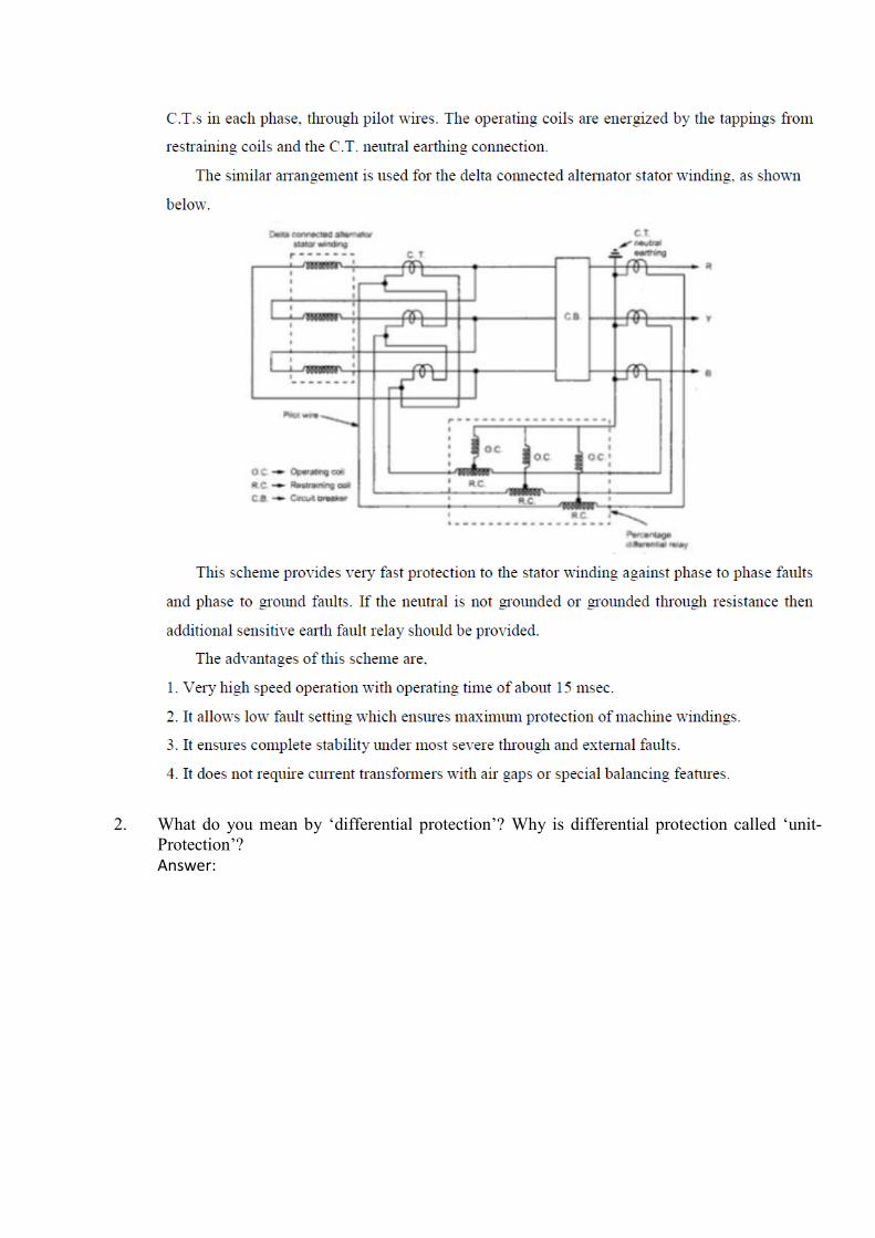
1. Describe with a neat sketch, the percentage Biased differential (Merz-Price scheme) protection of a modern alternator. Answer:
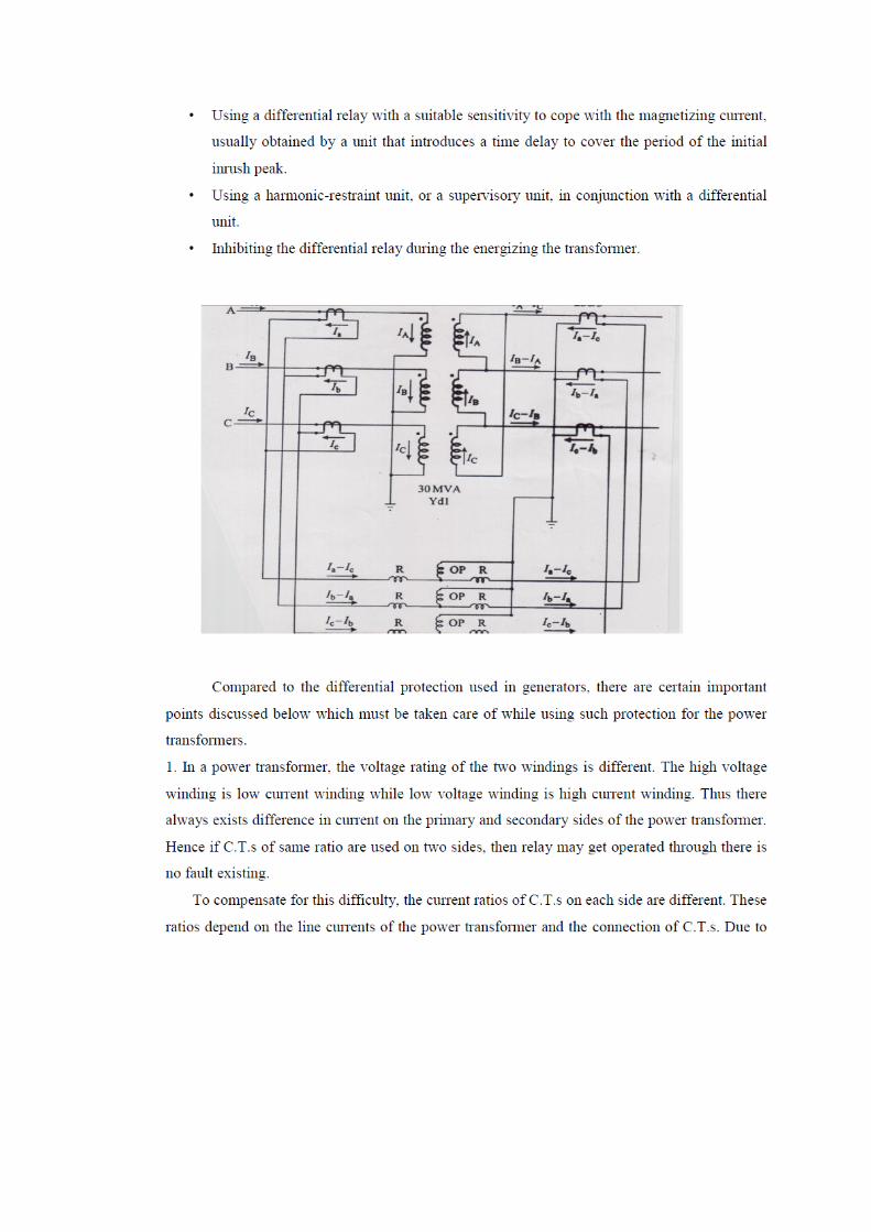
2. What do you mean by ‘differential protection’? Why is differential protection called ‘unit-Protection’? Answer:

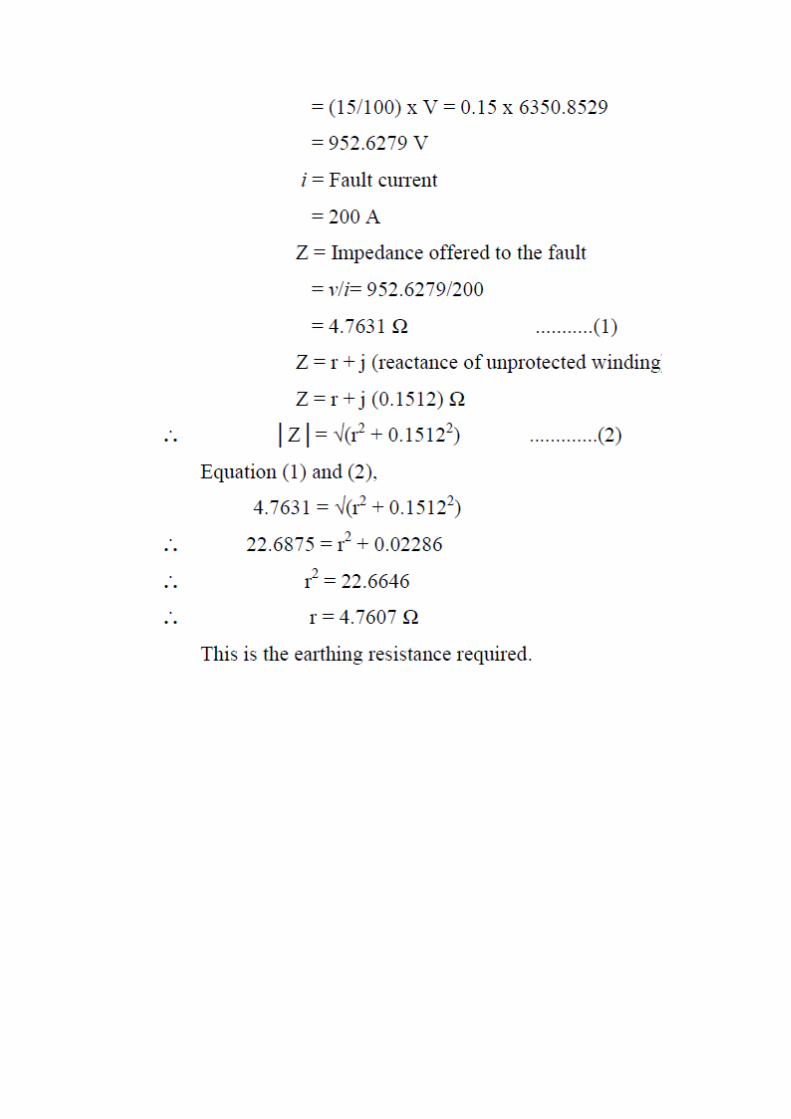
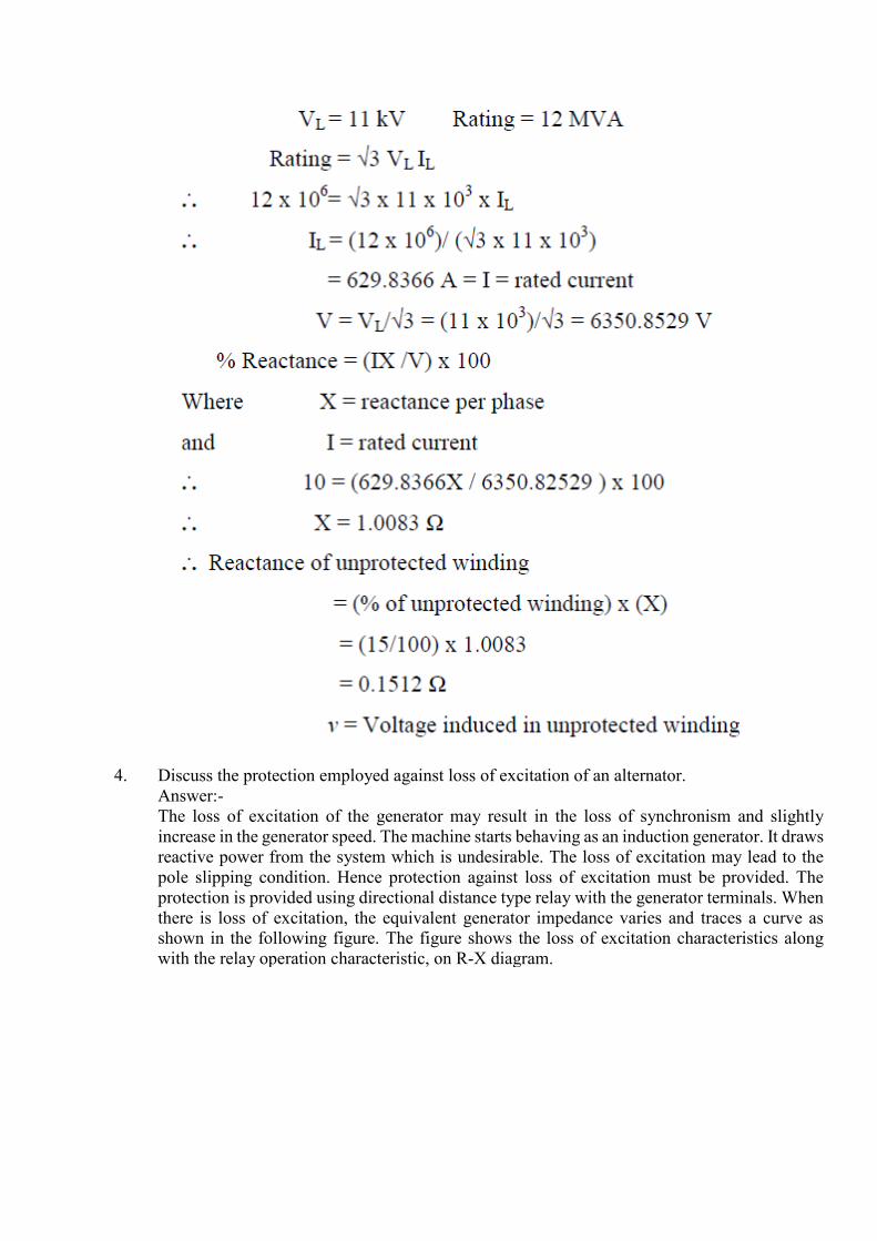
3. A star connected 3 phase, 12MVA, 11 kV alternator has a phase reactance of 10%. It is
protected by Merz-Price circulating current scheme which is set to operate for fault current not less than 200A. Calculate the value of earthing resistance to be provided in order to ensure that only 15% of the alternator winding remains unprotected. Answer:
4. Discuss the protection employed against loss of excitation of an alternator.
Answer:- The loss of excitation of the generator may result in the loss of synchronism and slightly increase in the generator speed. The machine starts behaving as an induction generator. It draws reactive power from the system which is undesirable. The loss of excitation may lead to the pole slipping condition. Hence protection against loss of excitation must be provided. The protection is provided using directional distance type relay with the generator terminals. When there is loss of excitation, the equivalent generator impedance varies and traces a curve as shown in the following figure. The figure shows the loss of excitation characteristics along with the relay operation characteristic, on R-X diagram.

The equivalent generator impedance locus traces a path from first quadrant of R-X diagram to the fourth quadrant. The distance relay is used which covers the portion of the fourth quadrant where impedance locus path exists. Thus when the impedance takes value in the region covered by the relay characteristics, the relay operates. The relay operates when generator first starts to slip poles. Then relay trips the field circuit breaker. And it disconnects the generator from the system, too. When the excitation is regained and becomes normal, the generator can then be returned to service instantly.
5. A three-phase power transformer having a line voltage ratio of 400 V to 33 kV is connected in star-delta. The C.T.s on 400V side have current ratio as 1000/5. What must be the C.T. ratio on 33 kV side? Answer:
On the primary side, which is 400 V side of transformer the current is 1000 A. Hence C.T.s primary will carry current of 1000 A. The C.T. ratio is 1000/5 on the primary side hence the current in C.T. Secondaries which is phase current of delta connected C.T.s is, Ip = 1000 x (5/1000) = 5 A This is shown in the Fig IL =√3 Ip = 5√3 A This is balance the C.T. secondaries are connected in delta. The same current flows through the star connected C.T. secondaries.

Hence each secondaries of C.T. on the secondary side of transformer carries a current of 5√3 A. For the power transformer the apparent power on both sides must be same. Primary apparent power = Secondary apparent power √3 VL1 IL1 = √3 VL2 IL2 √3 x 400 x 1000 = √3 x 33000 x IL2 IL2 = (400 x 1000)/33000 = 12.12 A Thus each primary of C.T.s connected in star carries a current of 12.12 A.while each secondary of C.T.s connected in star carries a current of 5√3 A. Hence the C.T. ratio on 33 kV side is, C.T. ratio = Primary current/Secondary current = 12.12/5√3 = 1.4 : 1 This is the required C.T. ratio on 33 kV side.
6 What is Buchholz relay? Discuss its operation, advantages, limitations and applications of Buchholz relay. Answer: - All faults below the oil in transformer result in the localized heating & breakdown of the oil, some degree of arcing will always take place in a winding fault & the resulting decomposition of it will release gases such as hydrogen, carbon monoxide & hydrocarbons. • When the fault is of a very minor type, such as hot joints gas is released slowly, but a major fault involving severe arcing causes rapid release of large volumes of gas as well as oil vapour.
• Such incipient faults of smaller or larger magnitudes can be detected by a gas actuated relay known as Bucholtz Relay. The Bucholtz Relay is contained in a cast housing which is connected as shown below between the conservator tank and main tank of the transformer.
Under normal conditions, the Buchholz relay is full of oil. It consists of a cast housing containing a hinged hollow float. A mercury switch is attached to a float. The float being rotated in the upper part of the housing. Another hinged flap valve is located in the lower part which is directly in the path of the oil between tank and the conservator. Another mercury switch is attached to a flap valve. The float closes the alarm circuit while the lower flap valve closes the trip circuit in case of internal faults. Operation: There are many types of internal faults such as insulation fault, core heating, bad switch contacts, faulty joints etc. which can occur. When the fault occurs the decomposition of oil in the main tank starts due to which the gases are generated. As mentioned earlier, major component of such gases is hydrogen. The hydrogen tries to rise up towards conservator but in

its path it gets accumulated in the upper part of the Buchholz relay. Through passage of the gas is prevented by the flap valve. When gas gets accumulated in the upper part of housing, the oil level inside the housing falls. Due to which the hollow float tilts and closes the contacts of the mercury switch attached to it. This completes the alarm circuit to sound an alarm. Due to this operator knows that there is some incipient fault in the transformer. The transformer is disconnected, and the gas sample is tested. The testing results give the indication, what type of fault is started developing in the transformer. Hence transformer can be disconnected before grows into a serious one. The alarm circuit does not immediately disconnect the transformer but gives only an indication to the operator. This is because sometimes bubbles in the oil circulating system may operate the alarm circuit even though actually there is no fault. However if a serious fault such as internal short circuit between phases, earth fault inside the tank etc. occurs then the considerable amount of gas gets generated. In that case, due to a fast reduction in the level of oil, the pressure in the tank increases. Due to this the oil rushes towards the conservator. While doing so it passes through the relay where flap valve is present. The flap valve gets deflected due to the rushing oil and operates the mercury switch, thereby energizing the trip circuit which opens the circuit breaker of transformer is totally disconnected from the supply. The connecting pipe between the tank and the conservator should be as straight as possible and should slope upwards conservator at a small angle from the horizontal. This angle should be around 100. For the economic considerations, Buchholz relays are not provided for the transformer having rating below 500 KVA. Advantages:
• Normally a protective relay does not indicate the appearance of the fault. It operates when fault occurs. But Buchholz relay gives an indication of the fault at very early stage, by anticipating the fault and operating the alarm circuit. Thus the transformer can be taken out of service before any type of serious damage occurs.
• It is the simplest protection in case of transformers. Application:
• Local overheating • Entrance of air bubbles in oil • Core bolt insulation failure • Short circuited laminations • Loss of oil and reduction in oil level due to leakage • Bad and loose electrical contacts • Short circuit between phases • Winding short circuit • Bushing puncture