Mustang Mach I 2003-2004 Intercooled System · PDF fileMustang Mach I 2003-2004 Intercooled...
32
Mustang Mach I 2003-2004 Intercooled System Installation Guide The Intercooled Supercharging Experts! ® ®
Transcript of Mustang Mach I 2003-2004 Intercooled System · PDF fileMustang Mach I 2003-2004 Intercooled...

Mustang Mach I 2003-2004 Intercooled System
Installation Guide
The Intercooled Supercharging Experts!®
®
© 2006 Accessible Technologies, Inc.
Accessible Technologies, Inc. 14801 W. 114th Terrace
Lenexa, KS 66215 Phone: 913.338.2886
Fax: 913.338.2879 [email protected]
All rights reserved. Accessible Technologies Inc. hereby grants permission to use and reproduce this document for personal use, provided that all copyright information be retained. Reproduction of this document for unauthorized commercial use is strictly prohibited.
Information in this document is subject to change without notice.
ProCharger is a registered trademark and The Intercooled Supercharging Experts!TM and Designed to Blow Away the CompetitionTM are trademarks of Accessible Technologies, Inc. and may not be used without express permission.
Revised 6/12 Part Number PMFL1A-001 Rev. C Printed in the USA
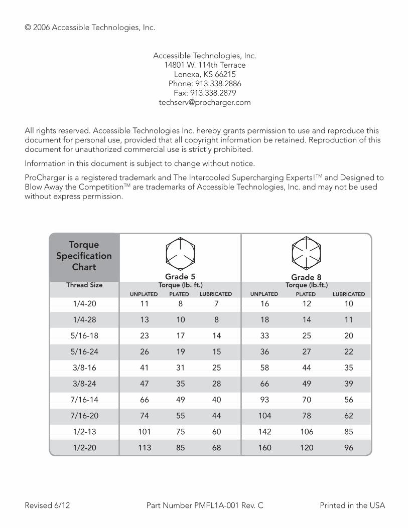
Grade 5 Grade 8
TorqueSpecification
Chart
Thread Size Torque (lb. ft.) Torque (lb.ft.)
1/4-20 11 8 7 16 12 10
1/4-28 13 10 8 18 14 11
5/16-18 23 17 14 33 25 20
5/16-24 26 19 15 36 27 22
3/8-16 41 31 25 58 44 35
3/8-24 47 35 28 66 49 39
7/16-14 66 49 40 93 70 56
7/16-20 74 55 44 104 78 62
1/2-13 101 75 60 142 106 85
1/2-20 113 85 68 160 120 96
UNPLATED PLATED LUBRICATED UNPLATED PLATED LUBRICATED
iFord Mustang Mach I 2003-2004 System Installation Guide i
Introduction
Congratulations on purchasing your ProCharger® Ford Mustang Mach I 2003-2004 Intercooled System. Read this entire manual before you attempt to install your ProCharger kit. It is imperative that you follow all of the instructions in the order they appear in this installation guide. If you have any questions regarding any aspect of this installation, call us at (913) 338-3086.
For best results, we recommend reviewing the installation instructions beforehand, and following the installation instructions closely and in sequence. A detailed packing list has been provided to assist you in identifying the components of your ProCharger system.
Required Tools and Supplies• 1/2” and 3/8” Socket Sets (standard & metric) • 3/8” Hex Bit Set (allen head) • 1/2” and 3/8” Breaker Bars and 4” Extensions • 3/8” Torx Bit Set • Open End Wrench Set (standard & metric) • Adjustable Wrench • Flat Screwdrivers • Phillips Screwdrivers • Plier Set • Fuel Line Tool Set • Spark Plug Socket • Ford Factory Repair Manual
Warning: Your supercharged Mustang Mach I must always be run on 91 octane or higher gas.
You should also have the following gauges available to properly check the finished installation and monitor your vehicle’s performance (especially for testing):• Manifold Boost Pressure Gauge • Fuel Pressure Gauge • Wide Band Oxygen Sensor and Gauge
Gauges should be of a type that can be read from the cockpit while performing a wide-open throttle road test. Cockpit or hood-mounted gauges are preferable. In order to obtain usable readings, the gauges should measure pressure at the intake manifold and fuel rail. IF VEHICLE DOES NOT MAINTAIN PROPER FUEL PRESSURE, DECREASE THROTTLE APPLICATION IMMEDIATELY. In some cases, extra vehicle modifications can strain the stock fuel pump. If your vehicle has difficulty retaining adequate fuel pressure, contact ATI ProCharger about the availability of an upgraded fuel system.
The engine on which the ProCharger® is to be installed should retain the factory compression ratio. If it has been modified in any way, please consult ProCharger staff before proceeding with the installation. This supercharger system is intended for use on STOCK, strong, well-maintained engines/transmissions. Installation on a worn or troublesome powertrain should be reconsidered. ATI PROCHARGER WILL NOT BE HELD RESPONSIBLE FOR DAMAGE TO A VEHICLE’S POWERTRAIN. ATI ProCharger is not responsible for ECM tuning/programming on non-stock vehicles. ATI PROCHARGER recommends verifying that your vehicle has current ECM updates from the vehicle manufacturer before installation.
For best performance and reliability, always use premium grade fuel (91 octane or higher) and listen closely for signs of detonation, which might sound like ball bearings rolling around in a tin can. IF DETONATION SHOULD OCCUR, OR IF YOU ARE UNSURE WHETHER WHAT YOU’RE HEARING IS DETONATION, DECREASE THROTTLE APPLICATION IMMEDIATELY and please consult ATI ProCharger staff. Detonation should not be an issue with a properly installed intercooled supercharger system, though OEM factory-shipped engine and parts inconsistencies are possible on any vehicle.
ii ii Ford Mustang Mach I 2003-2004 System Installation Guide
Introduction
Table of ConTenTs
Introduction .................................................................................................................................. i
Table of Contents ..........................................................................................................................ii
Getting Started ............................................................................................................................ 1
Fuel Injector Replacement ........................................................................................................... 3
ProCharger Head Unit ................................................................................................................. 4
Intercooler and Tubing ................................................................................................................. 6
Fuel Pump .................................................................................................................................. 10
Final Assembly ........................................................................................................................... 13
ECM Tuning/Supplemental Notes .............................................................................................. 16
Installation Review & Safety Check ............................................................................................ 19
Operation and Maintenance ...................................................................................................... 20
Limited Warranty ....................................................................................................................... 22
ProCharger Extended Coverage ................................................................................................ 23
Notes ......................................................................................................................................... 24
IF YOU PURCHASED THE OPTIONAL HANDHELD TUNER, PLEASE PROCEED TO THE ECM TUNING SECTION. TUNING THESE VEHI-CLES WITH THE DIABLO TUNER IS A MULTI-STEP PROCESS THAT SHOULD BE INTIATED BEFORE SYSTEM INSTALLATION BEGINS. PLEASE ALLOW 24 HOURS TO RECEIVE YOUR MODIFIED TUNE FILE. CONTACT ATI WITH ANY QUESTIONS REGARDING TUNING FOR THESE VEHICLES.

1Ford Mustang Mach I 2003-2004 System Installation Guide 1
Getting Started
Note: Spark plugs should be replaced if they are platinum or have more than 10,000 miles of use. Plugs that are one heat range colder than stock are recommended.
1 Disconnect the negative (-) battery cable from the battery.
2 Remove the coolant reservoir, without disconnecting any hoses or sensors, and set it aside to allow access to the front of the engine.
3 Remove the shaker scoop assembly, main support bracket and front mounting bracket (cast bracket attached at both sides of engine).
4 Remove the crankcase vent tubes from the valve covers (located at driver’s side rear and passenger’s side front). Retain one 5/8” X 3/4” reducer attached to the hose for re-installation on driver’s side valve cover.
5 Remove the air filter housing, MAF sensor, inlet duct and all related components connected to the throttle body. Disconnect the MAF sensor, remove it from the inlet duct and retain for re-installation.
Read and understand all safety precautions in this manual before installation. Failure to comply with instructions in this manual could result in personal injury, property damage, and/or voiding your warranty.
GeTTinG sTarTed
Inlet Duct/MAF Assembly
Shaker Assembly
Front Shaker Mount
Shaker Duct
Upper Radiator Hose/Coolant Manifold
PCV Hose
Initial Engine Preparation

2 2 Ford Mustang Mach I 2003-2004 System Installation Guide
Getting Started
6 After the engine has cooled completely, drain approximately one gallon of coolant from the vehicle. Disconnect the radiator hoses from the coolant transfer manifold near the alternator. Disconnect and remove the upper hose from the radiator. Disconnect the wiring from the sensors located on the coolant manifold assembly. Remove the two coolant manifold retainer nuts from the engine. Remove the bracket and coolant manifold assembly from the engine.
7 Remove the serpentine accessory drive belt.
Tech Tip: The factory belt routing will not be interrupted by the ProCharger, and the original belt may be re-installed (bypassing the ProCharger) in the event of a drive belt failure.
8 Raise the vehicle, secure with jackstands, and lock the wheels to the left.
9 Remove the driver’s side lower plastic splash panel to allow access to the driver’s side of the engine compartment.
Tech Tip: Removing both front wheels, the passenger’s side splash panel and the inner fender well liner may simplify the following procedure.
10 Remove the coolant reservoir mounting bar that extends upwards from the rear of the core support. This item will not be reused.
11 If so equipped, remove any aftermarket ECM module.
Warning: Aftermarket ECM modules, unless specifically designed for use with a supercharger, advance timing at elevated rpm’s, and in most cases will cause detonation and engine damage under boost conditions.
3Ford Mustang Mach I 2003-2004 System Installation Guide 3
Fuel Injector Replacement
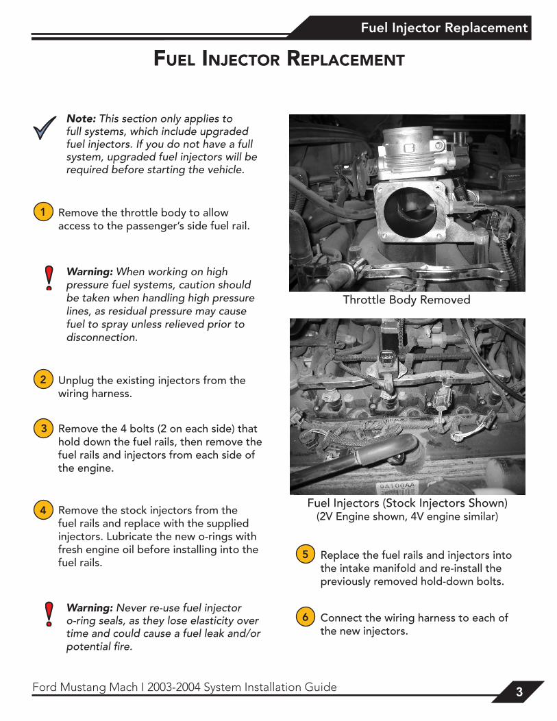
Note: This section only applies to full systems, which include upgraded fuel injectors. If you do not have a full system, upgraded fuel injectors will be required before starting the vehicle.
1 Remove the throttle body to allow access to the passenger’s side fuel rail.
Warning: When working on high pressure fuel systems, caution should be taken when handling high pressure lines, as residual pressure may cause fuel to spray unless relieved prior to disconnection.
2 Unplug the existing injectors from the wiring harness.
3 Remove the 4 bolts (2 on each side) that hold down the fuel rails, then remove the fuel rails and injectors from each side of the engine.
4 Remove the stock injectors from the fuel rails and replace with the supplied injectors. Lubricate the new o-rings with fresh engine oil before installing into the fuel rails.
Warning: Never re-use fuel injector o-ring seals, as they lose elasticity over time and could cause a fuel leak and/or potential fire.
5 Replace the fuel rails and injectors into the intake manifold and re-install the previously removed hold-down bolts.
6 Connect the wiring harness to each of the new injectors.
fuel injeCTor replaCemenT
Throttle Body Removed
Fuel Injectors (Stock Injectors Shown)(2V Engine shown, 4V engine similar)
4 4 Ford Mustang Mach I 2003-2004 System Installation Guide
ProCharger Head Unit
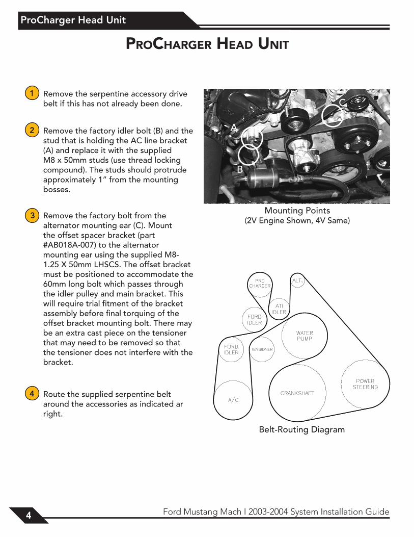
1 Remove the serpentine accessory drive belt if this has not already been done.
2 Remove the factory idler bolt (B) and the stud that is holding the AC line bracket (A) and replace it with the supplied M8 x 50mm studs (use thread locking compound). The studs should protrude approximately 1” from the mounting bosses.
3 Remove the factory bolt from the alternator mounting ear (C). Mount the offset spacer bracket (part #AB018A-007) to the alternator mounting ear using the supplied M8-1.25 X 50mm LHSCS. The offset bracket must be positioned to accommodate the 60mm long bolt which passes through the idler pulley and main bracket. This will require trial fitment of the bracket assembly before final torquing of the offset bracket mounting bolt. There may be an extra cast piece on the tensioner that may need to be removed so that the tensioner does not interfere with the bracket.
4 Route the supplied serpentine belt around the accessories as indicated ar right.
proCharGer head uniT
Belt-Routing Diagram
A
B
C
Mounting Points(2V Engine Shown, 4V Same)
5Ford Mustang Mach I 2003-2004 System Installation Guide 5
ProCharger Head Unit
A
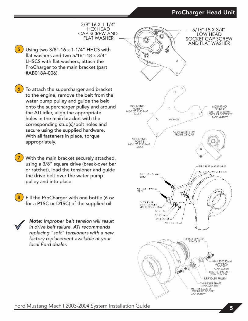
5 Using two 3/8”-16 x 1-1/4” HHCS with flat washers and two 5/16”-18 x 3/4” LHSCS with flat washers, attach the ProCharger to the main bracket (part #AB018A-006).
6 To attach the supercharger and bracket to the engine, remove the belt from the water pump pulley and guide the belt onto the supercharger pulley and around the ATI idler, align the appropriate holes in the main bracket with the corresponding stud(s)/bolt holes and secure using the supplied hardware. With all fasteners in place, torque appropriately.
7 With the main bracket securely attached, using a 3/8” square drive (break-over bar or ratchet), load the tensioner and guide the drive belt over the water pump pulley and into place.
8 Fill the ProCharger with one bottle (6 oz for a P1SC or D1SC) of the supplied oil.
Note: Improper belt tension will result in drive belt failure. ATI recommends replacing “soft” tensioners with a new factory replacement available at your local Ford dealer.
(.190X.328X.450)
(.190X.328X.450)
6 6 Ford Mustang Mach I 2003-2004 System Installation Guide
Intercooler and Tubing
ME
TAL
TUB
ES
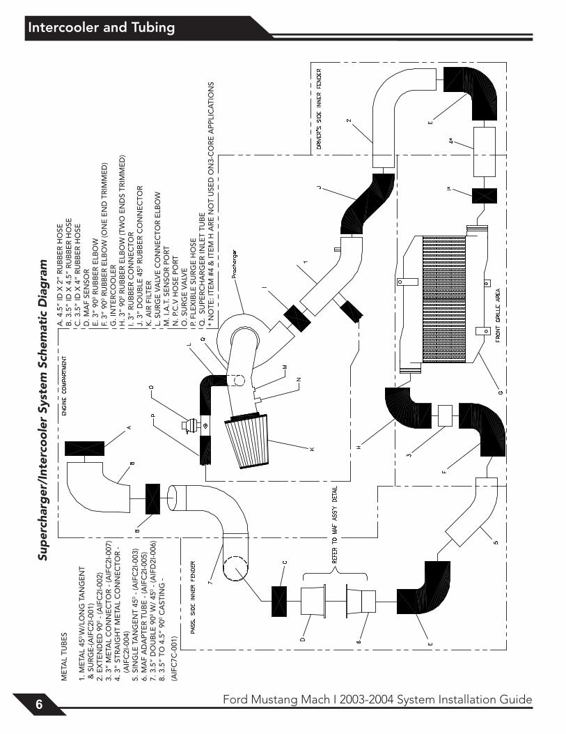
1. M
ETA
L 45
0 W/L
ON
G T
AN
GE
NT
& S
UR
GE
-(AIF
C2I
-001
)2.
EX
TEN
DE
D 9
00 - (A
IFC
2I-0
02)
3. 3
” M
ETA
L C
ON
NE
CTO
R -
(AIF
C2I
-007
)4.
3”
STR
AIG
HT
ME
TAL
CO
NN
EC
TOR
-
(AIF
C2I
-004
)5.
SIN
GLE
TA
NG
EN
T 45
0 - (A
IFC
2I-0
03)
6. M
AF
AD
APT
ER
TU
BE
- (A
IFC
2I-0
05)
7. 3
.5”
DO
UB
LE 9
00 W/
450 -
(AIF
D2I
-006
)8.
3.5
” TO
4.5
” 90
0 CA
STIN
G -
(AIF
C7C
-001
)
A. 4
.5”
ID X
2”
RU
BB
ER
HO
SEB
. 3.5
” ID
X 4
.5”
RU
BB
ER
HO
SEC
. 3.5
” ID
X 4
” R
UB
BE
R H
OSE
D. M
AF
SEN
SOR
E. 3
” 90
0 RU
BB
ER
ELB
OW
F. 3
” 90
0 RU
BB
ER
ELB
OW
(ON
E E
ND
TR
IMM
ED
)G
. IN
TER
CO
OLE
RH
. 3”
900 R
UB
BE
R E
LBO
W (T
WO
EN
DS
TRIM
ME
D)
I. 3”
RU
BB
ER
CO
NN
EC
TOR
J. 3
” D
OU
BLE
450 R
UB
BE
R C
ON
NE
CTO
RK
. AIR
FIL
TER
L. S
UR
GE
VA
LVE
CO
NN
EC
TOR
ELB
OW
M. I
.A.T
. SE
NSO
R P
ORT
N. P
.C.V
HO
SE P
ORT
O. S
UR
GE
VA
LVE
P. F
LEX
IBLE
SU
RG
E H
OSE
Q.
SUPE
RC
HA
RG
ER
INLE
T TU
BE
* N
OTE
: ITE
M #
4 &
ITE
M H
AR
E N
OT
USE
D O
N3-
CO
RE
APP
LIC
ATI
ON
S
Sup
erch
arg
er/I
nter
coo
ler
Syst
em S
chem
atic
Dia
gra
m
7Ford Mustang Mach I 2003-2004 System Installation Guide 7
Intercooler and Tubing
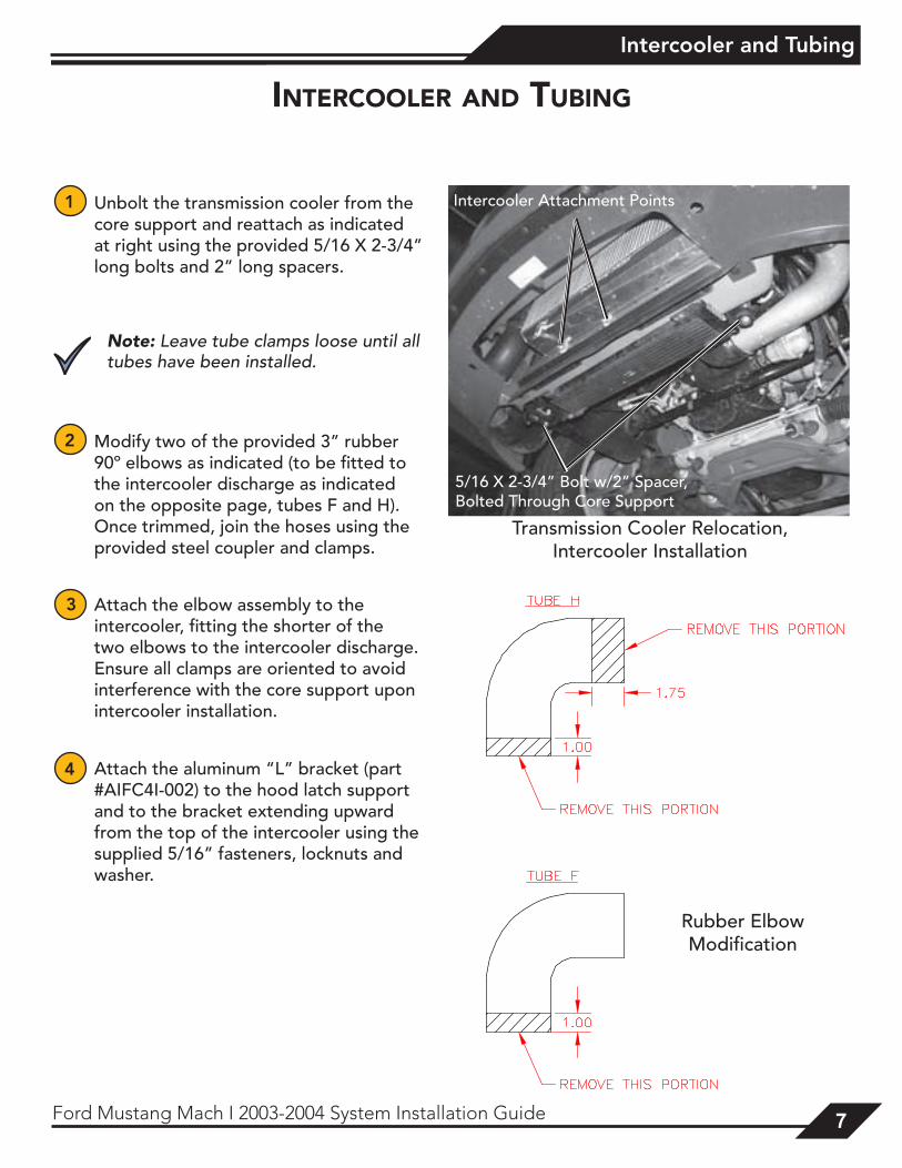
1 Unbolt the transmission cooler from the core support and reattach as indicated at right using the provided 5/16 X 2-3/4” long bolts and 2” long spacers.
Note: Leave tube clamps loose until all tubes have been installed.
2 Modify two of the provided 3” rubber 90º elbows as indicated (to be fitted to the intercooler discharge as indicated on the opposite page, tubes F and H). Once trimmed, join the hoses using the provided steel coupler and clamps.
3 Attach the elbow assembly to the intercooler, fitting the shorter of the two elbows to the intercooler discharge. Ensure all clamps are oriented to avoid interference with the core support upon intercooler installation.
4 Attach the aluminum “L” bracket (part #AIFC4I-002) to the hood latch support and to the bracket extending upward from the top of the intercooler using the supplied 5/16” fasteners, locknuts and washer.
inTerCooler and TubinG
Rubber Elbow Modification
Transmission Cooler Relocation, Intercooler Installation
Intercooler Attachment Points
5/16 X 2-3/4” Bolt w/2” Spacer, Bolted Through Core Support

8 8 Ford Mustang Mach I 2003-2004 System Installation Guide
Intercooler and Tubing
5 Using the provided 5/16 bolts and locknuts, attach the intercooler to the lower core support using the two lower mounting tabs and corresponding holes in the core support.
6 Install hoses and clamps on intercooler tubes, allowing plenty of overlap between hoses and steel tubes, with the hose clamps located behind the connector beads.
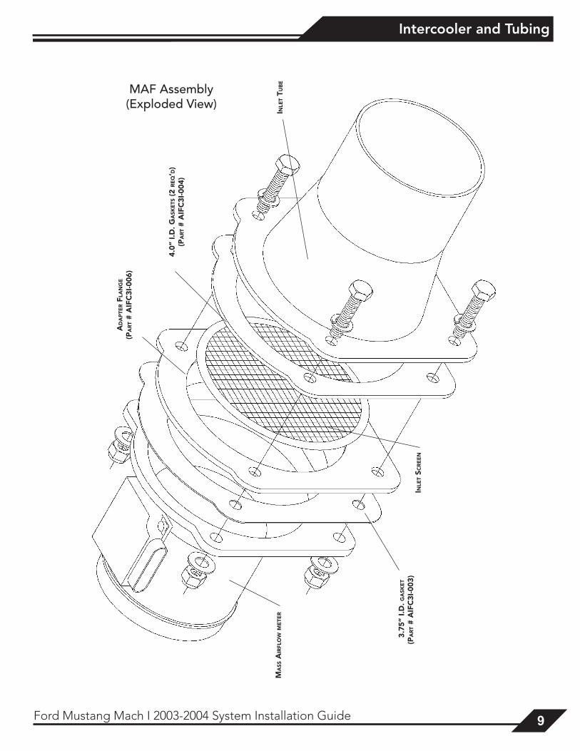
7 Using the supplied flange, gaskets, adapter tube and 1/4” hardware, assemble the MAF sensor assembly as shown on the opposite page.
Note: There is a slight offset in the gaskets and the flange. Verify concentric alignment of all components before tightening the bolts.
8 Using the factory hardware, bolt the provided tube support bracket to the inner fender using the air dam mounting studs. Attach the MAF tube assembly to the support bracket using the provided clamp.
9 Check all clamped connections and verify that they are tightened properly.
9Ford Mustang Mach I 2003-2004 System Installation Guide 9
Intercooler and Tubing
ad
ap
Ter f
lan
Ge
(pa
rT
# a
ifC
3i-0
06)
ma
ss a
irfl
ow
me
Ter
3.7
5” i.
d. G
ask
eT
(pa
rT
# a
ifC
3i-0
03)
inle
T sC
re
en
4.0”
i.d
. Ga
ske
Ts (
2 r
eq
’d)
(pa
rT
# a
ifC
3i-0
04)
inle
T Tu
be
MAF Assembly(Exploded View)
1010 Ford Mustang Mach I 2003-2004 System Installation Guide
Fuel Pump
Note: This section only applies to full systems, which include a high flow fuel pump. If you do not have a full system, additional fuel system modificatons will be required before starting the vehicle.
Warning: When working on high pressure fuel systems, caution should be taken when handling high pressure lines, as residual pressure may cause fuel to spray unless relieved prior to disconnection.
Tech Tip: This procedure may be simplified by emptying the fuel tank prior to removal.
1 Raise the rear of the vehicle and support it with jack stands under the frame, allowing the suspension to hang free.
2 Disconnect the fuel filler neck by removing the three screws located at the fuel filler neck, behind the fuel filler door.
3 Place a floorjack or similar support mechanism beneath the tank. Loosen and remove the tank support straps and allow the tank to rest against the floorjack. Slowly lower the tank from the vehicle to provide access to the fuel line.
fuel pump
11Ford Mustang Mach I 2003-2004 System Installation Guide 11
Fuel Pump
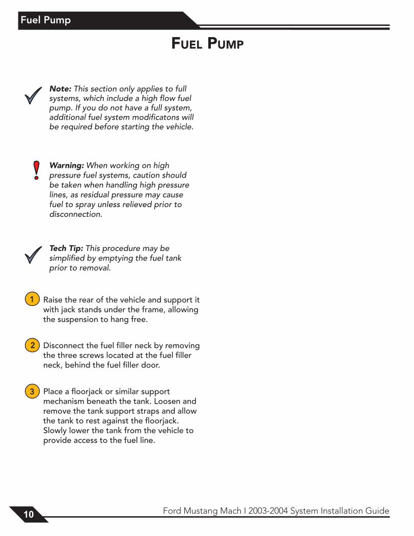
4 Disconnect the fuel line (using a fuel line tool) and all wiring from the fuel tank and remove the fuel tank from the vehicle.
5 Remove the fuel pump canister assembly from the tank.
6 Remove the retaining screws that hold the canister together and the hoses down.
7 Pull the hose (hat) off the top of the fuel pump.
Fuel Pump Canister Assembly
Six Retaining Screws
Hose Removal
1212 Ford Mustang Mach I 2003-2004 System Installation Guide
Fuel Pump
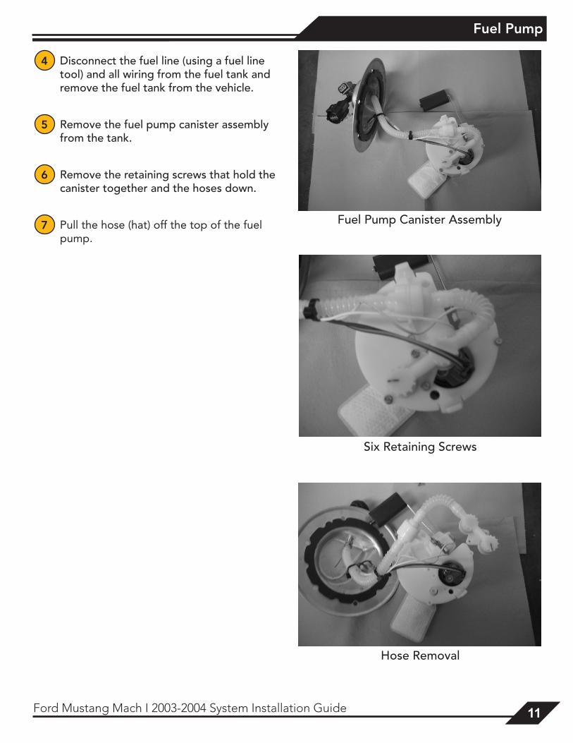
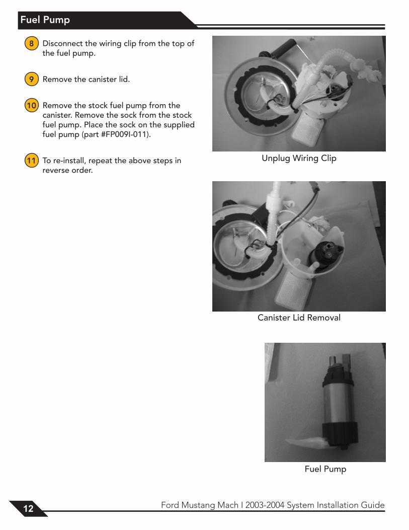
8 Disconnect the wiring clip from the top of the fuel pump.
9 Remove the canister lid.
10 Remove the stock fuel pump from the canister. Remove the sock from the stock fuel pump. Place the sock on the supplied fuel pump (part #FP009I-011).
11 To re-install, repeat the above steps in reverse order.
Unplug Wiring Clip
Canister Lid Removal
Fuel Pump
13Ford Mustang Mach I 2003-2004 System Installation Guide 13
Final Assembly
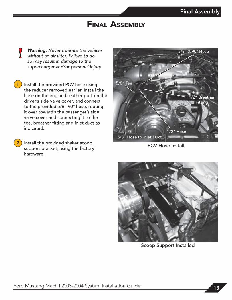
Warning: Never operate the vehicle without an air filter. Failure to do so may result in damage to the supercharger and/or personal injury.
1 Install the provided PCV hose using the reducer removed earlier. Install the hose on the engine breather port on the driver’s side valve cover, and connect to the provided 5/8” 90º hose, routing it over toward’s the passenger’s side valve cover and connecting it to the tee, breather fitting and inlet duct as indicated.
2 Install the provided shaker scoop support bracket, using the factory hardware.
final assembly
PCV Hose Install
5/8” X 90º Hose
1/2” Breather Fitting
1/2” Hose
5/8” Tee
5/8” Hose to Inlet Duct
Scoop Support Installed
1414 Ford Mustang Mach I 2003-2004 System Installation Guide
Final Assembly
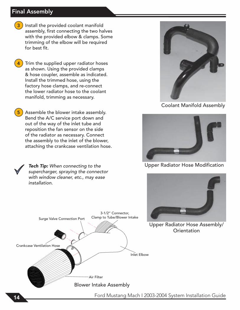
3 Install the provided coolant manifold assembly, first connecting the two halves with the provided elbow & clamps. Some trimming of the elbow will be required for best fit.
4 Trim the supplied upper radiator hoses as shown. Using the provided clamps & hose coupler, assemble as indicated. Install the trimmed hose, using the factory hose clamps, and re-connect the lower radiator hose to the coolant manifold, trimming as necessary.
5 Assemble the blower intake assembly. Bend the A/C service port down and out of the way of the inlet tube and reposition the fan sensor on the side of the radiator as necessary. Connect the assembly to the inlet of the blower, attaching the crankcase ventilation hose.
Tech Tip: When connecting to the supercharger, spraying the connector with window cleaner, etc., may ease installation.
Coolant Manifold Assembly
Upper Radiator Hose Modification
Upper Radiator Hose Assembly/Orientation
3-1/2” Connector, Clamp to Tube/Blower Intake
Air Filter
Inlet Elbow
Crankcase Ventilation Hose
Surge Valve Connection Port
Blower Intake Assembly
15Ford Mustang Mach I 2003-2004 System Installation Guide 15
Final Assembly
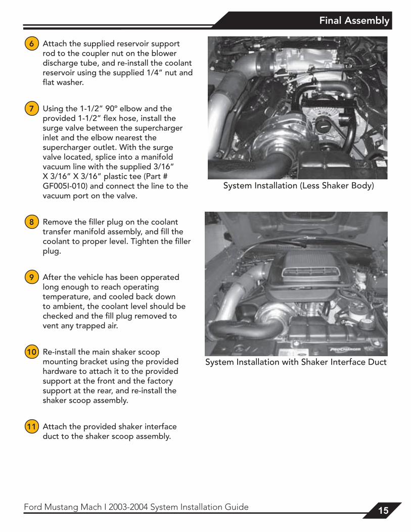
6 Attach the supplied reservoir support rod to the coupler nut on the blower discharge tube, and re-install the coolant reservoir using the supplied 1/4” nut and flat washer.
7 Using the 1-1/2” 90º elbow and the provided 1-1/2” flex hose, install the surge valve between the supercharger inlet and the elbow nearest the supercharger outlet. With the surge valve located, splice into a manifold vacuum line with the supplied 3/16” X 3/16” X 3/16” plastic tee (Part # GF005I-010) and connect the line to the vacuum port on the valve.
8 Remove the filler plug on the coolant transfer manifold assembly, and fill the coolant to proper level. Tighten the filler plug.
9 After the vehicle has been opperated long enough to reach operating temperature, and cooled back down to ambient, the coolant level should be checked and the fill plug removed to vent any trapped air.
10 Re-install the main shaker scoop mounting bracket using the provided hardware to attach it to the provided support at the front and the factory support at the rear, and re-install the shaker scoop assembly.
11 Attach the provided shaker interface duct to the shaker scoop assembly.
System Installation (Less Shaker Body)
System Installation with Shaker Interface Duct
1616 Ford Mustang Mach I 2003-2004 System Installation Guide
ECM Tuning/Supplemental Notes
eCm TuninG
Note: This section only applies to full systems, which include a hand-held tuner (optional) or chip. If you do not have a full system, additional tuning will be required before starting the vehicle.
Chip Installation Note: The majority of all chip problems
can be attributed to the failure to properly prepare the ECM contacts. Taking time to clean the terminals thoroughly will prevent problems later.
1 Verify that the negative (-) battery cable is disconnected from the battery.
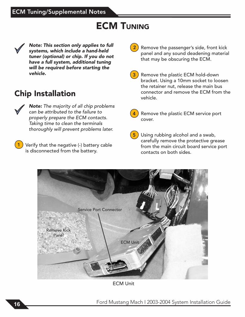
2 Remove the passenger’s side, front kick panel and any sound deadening material that may be obscuring the ECM.
3 Remove the plastic ECM hold-down bracket. Using a 10mm socket to loosen the retainer nut, release the main bus connector and remove the ECM from the vehicle.
4 Remove the plastic ECM service port cover.
5 Using rubbing alcohol and a swab, carefully remove the protective grease from the main circuit board service port contacts on both sides.
Remove Kick Panel
Service Port Connector
ECM Unit
ECM Unit

17Ford Mustang Mach I 2003-2004 System Installation Guide 17
ECM Tuning/Supplemental Notes
6 Using a scraper or razor blade, remove the protective lacquer from the contacts. As soon as the contacts begin to give off fine metal shavings, the contacts are clean. Take care to avoid removing any additional material, as doing so may damage the terminals and render the
port inoperable.
7 Once the service port contacts are clean, the chip may be installed. Align as indicated in the chip instructions.
8 Re-install the ECM in the vehicle.
9 Reconnect the negative (-) battery cable.
inTune Programmer Warning: Voltage fluctuations are a
common cause of reflashing failure. Be sure your battery is fully charged, remove the cooling fan and fuel pump fuses, keep the stereo off, and do not open or close any doors or windows while reflashing.
Warning: During a reflashing, either stay in the vehicle or open a window prior to reflashing to prevent getting locked out.
1 Remove the inTune programmer from its box and review the included instructions.
2 Connect the inTune programmer to the OBD-II port located below the steering column using the OBD-II cable included with your programmer.
3 Upload your stock tune from the ECM to the inTune programmer:
1) Select Tune Vehicle
2) Select Write Vehicle
4 When prompted, turn the key to the “on” position without starting the engine.
5 Once your vehicle is recognized:
1) Select Diablo Tuning
2) Select Modify Stock
6 Follow the on-screen prompts. Your original backup will be saved.
7 Connect the inTune programmer to your PC with the provided USB cable. Allow the device to load drivers to the PC.
8 Once the device drivers have loaded, a window will appear showing the inTune as an additional storage drive.
1) Select Open Files
2) Select Tunes
3) Click and drag the Original Backup file to your PC’s desktop
9 Email the Original Backup file to [email protected] with the ProCharger serial number in the subject line.
10 You will receive the tune for your vehicle within 24 hours. Save the modified tune to your desktop or hard drive.
1818 Ford Mustang Mach I 2003-2004 System Installation Guide
ECM Tuning/Supplemental Notes
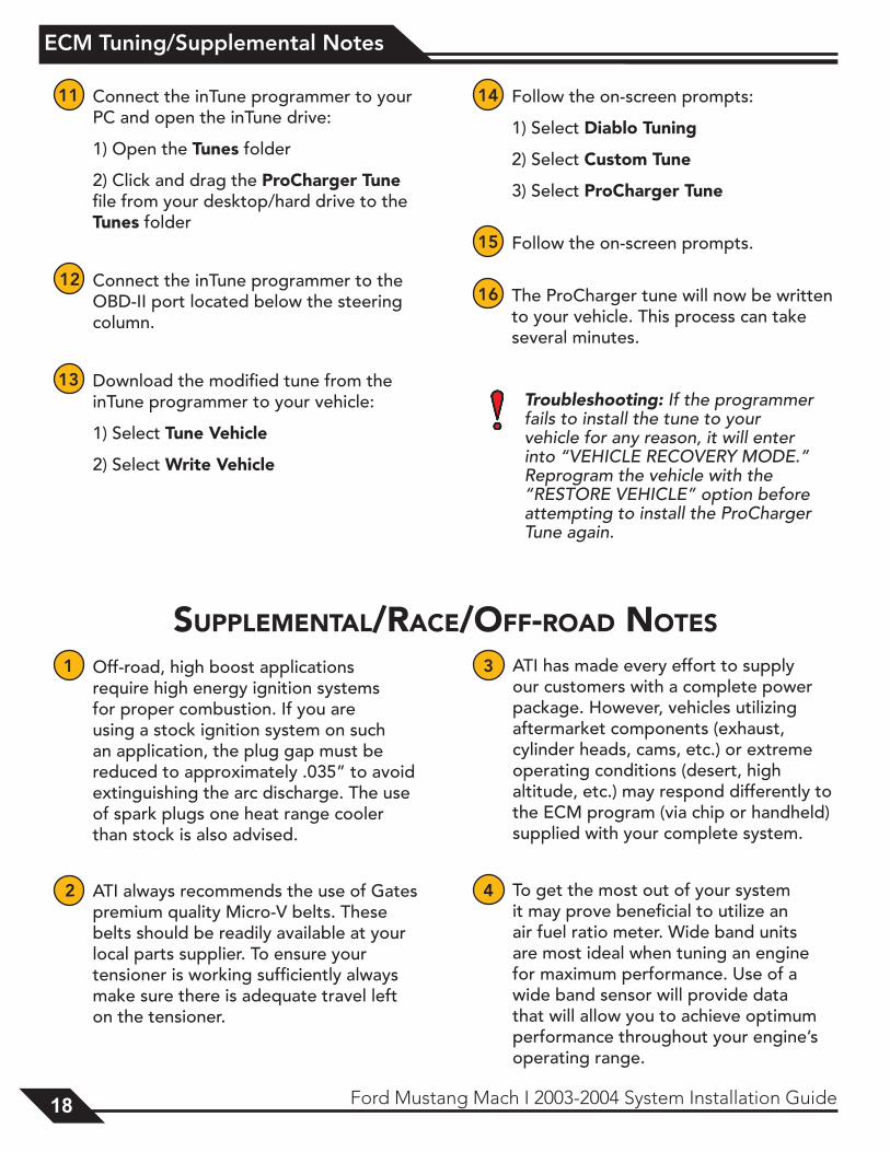
1 Off-road, high boost applications require high energy ignition systems for proper combustion. If you are using a stock ignition system on such an application, the plug gap must be reduced to approximately .035” to avoid extinguishing the arc discharge. The use of spark plugs one heat range cooler than stock is also advised.
2 ATI always recommends the use of Gates premium quality Micro-V belts. These belts should be readily available at your local parts supplier. To ensure your tensioner is working sufficiently always make sure there is adequate travel left on the tensioner.
3 ATI has made every effort to supply our customers with a complete power package. However, vehicles utilizing aftermarket components (exhaust, cylinder heads, cams, etc.) or extreme operating conditions (desert, high altitude, etc.) may respond differently to the ECM program (via chip or handheld) supplied with your complete system.
4 To get the most out of your system it may prove beneficial to utilize an air fuel ratio meter. Wide band units are most ideal when tuning an engine for maximum performance. Use of a wide band sensor will provide data that will allow you to achieve optimum performance throughout your engine’s operating range.
supplemenTal/raCe/off-road noTes
11 Connect the inTune programmer to your PC and open the inTune drive:
1) Open the Tunes folder
2) Click and drag the ProCharger Tune file from your desktop/hard drive to the Tunes folder
12 Connect the inTune programmer to the OBD-II port located below the steering column.
13 Download the modified tune from the inTune programmer to your vehicle:
1) Select Tune Vehicle
2) Select Write Vehicle
14 Follow the on-screen prompts:
1) Select Diablo Tuning
2) Select Custom Tune
3) Select ProCharger Tune
15 Follow the on-screen prompts.
16 The ProCharger tune will now be written to your vehicle. This process can take several minutes.
Troubleshooting: If the programmer fails to install the tune to your vehicle for any reason, it will enter into “VEHICLE RECOVERY MODE.” Reprogram the vehicle with the “RESTORE VEHICLE” option before attempting to install the ProCharger Tune again.
19Ford Mustang Mach I 2003-2004 System Installation Guide 19
Installation Review
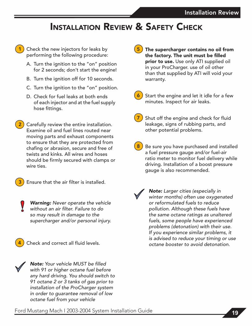
1 Check the new injectors for leaks by performing the following procedure:
A. Turn the ignition to the “on” position for 2 seconds; don’t start the engine!
B. Turn the ignition off for 10 seconds.
C. Turn the ignition to the “on” position.
D. Check for fuel leaks at both ends of each injector and at the fuel supply hose fittings.
2 Carefully review the entire installation. Examine oil and fuel lines routed near moving parts and exhaust components to ensure that they are protected from chafing or abrasion, secure and free of twists and kinks. All wires and hoses should be firmly secured with clamps or wire ties.
3 Ensure that the air filter is installed.
Warning: Never operate the vehicle without an air filter. Failure to do so may result in damage to the supercharger and/or personal injury.
4 Check and correct all fluid levels.
Note: Your vehicle MUST be filled with 91 or higher octane fuel before any hard driving. You should switch to 91 octane 2 or 3 tanks of gas prior to installation of the ProCharger system in order to guarantee removal of low octane fuel from your vehicle
5 The supercharger contains no oil from the factory. The unit must be filled prior to use. Use only ATI supplied oil in your ProCharger. use of oil other than that supplied by ATI will void your warranty.
6 Start the engine and let it idle for a few minutes. Inspect for air leaks.
7 Shut off the engine and check for fluid leakage, signs of rubbing parts, and other potential problems.
8 Be sure you have purchased and installed a fuel pressure gauge and/or fuel-air ratio meter to monitor fuel delivery while driving. Installation of a boost pressure gauge is also recommended.
Note: Larger cities (especially in winter months) often use oxygenated or reformulated fuels to reduce pollution. Although these fuels have the same octane ratings as unaltered fuels, some people have experienced problems (detonation) with their use. If you experience similar problems, it is advised to reduce your timing or use octane booster to avoid detonation.
insTallaTion review & safeTy CheCk
2020 Ford Mustang Mach I 2003-2004 System Installation Guide
Operation and Maintenance
operaTion and mainTenanCe
Cold StartingNever race your engine and ProCharger supercharger when your engine is cold. Allow the water temperature to climb into operating range for several minutes before driving above 2,500 rpm, to ensure adequate oil lubrication.
Fuel QualityWith a properly installed intercooled ProCharger supercharger system, detonation should not occur. For the best performance and reliability, use premium grade fuel (91 octane or higher). Listen for signs of detonation after refueling, and after replacement or modification of any fuel system component(s). If detonation occurs, reduce the throttle and locate the source.
Ignition System MaintenanceIf your spark plugs are more than a year old or have more than 10,000 miles logged, you should consider changing them before driving your vehicle under load. Spark plug wires should be changed if visibly damaged or when resistance exceeds factory specifications.
Air Filter MaintenanceYour air filters should be cleaned periodically, potentially as often as every 10,000 miles or 6 months, even though a service interval of 50,000 - 100,000 miles is quoted by the manufacturer under normal driving conditions. A clogged air filter will result in decreased boost levels and vehicle performance. Be sure to re-oil the cleaned filter before re-installing. Always operate your vehicle with an air filter, failure to do so may result in damage to your ProCharger supercharger and personal injury!
Belt ReplacementThe serpentine belt, which turns your ProCharger supercharger, will stretch after initial run-in, and should be retightened after the first hundred miles. Tighten the belt sufficiently to avoid slippage, but do not overtighten. Overtightening the belt could cause damage to the ProCharger supercharger’s precision bearings. When re-installing the belt, use the belt routing diagram in this manual. If you reuse a thrown belt and find that it needs frequent re-tightening, the belt is damaged and should be replaced. Gates Micro-V belts can be bought from ATI or from your local parts store.
ProCharger Oil Change IntervalsThe first oil change should be performed at 500 miles and at 6,000 mile intervals thereafter. Clean drain plug after every oil change. Drain oil by removing the drain plug. Clean off drain plug before re-installing.
Misc. Parts:•4.00” Drive Pulley (DP400I-6SSD) = DB109I-006 Belt (Gates #K061098)•1.95” Idler Pulley = DC003A-61SM•Idler Shaft (.190x.328x.450) = DM002I-033•Idler Shaft (.480x.328x.100) = DM002I-034
21Ford Mustang Mach I 2003-2004 System Installation Guide 21
Operation and Maintenance
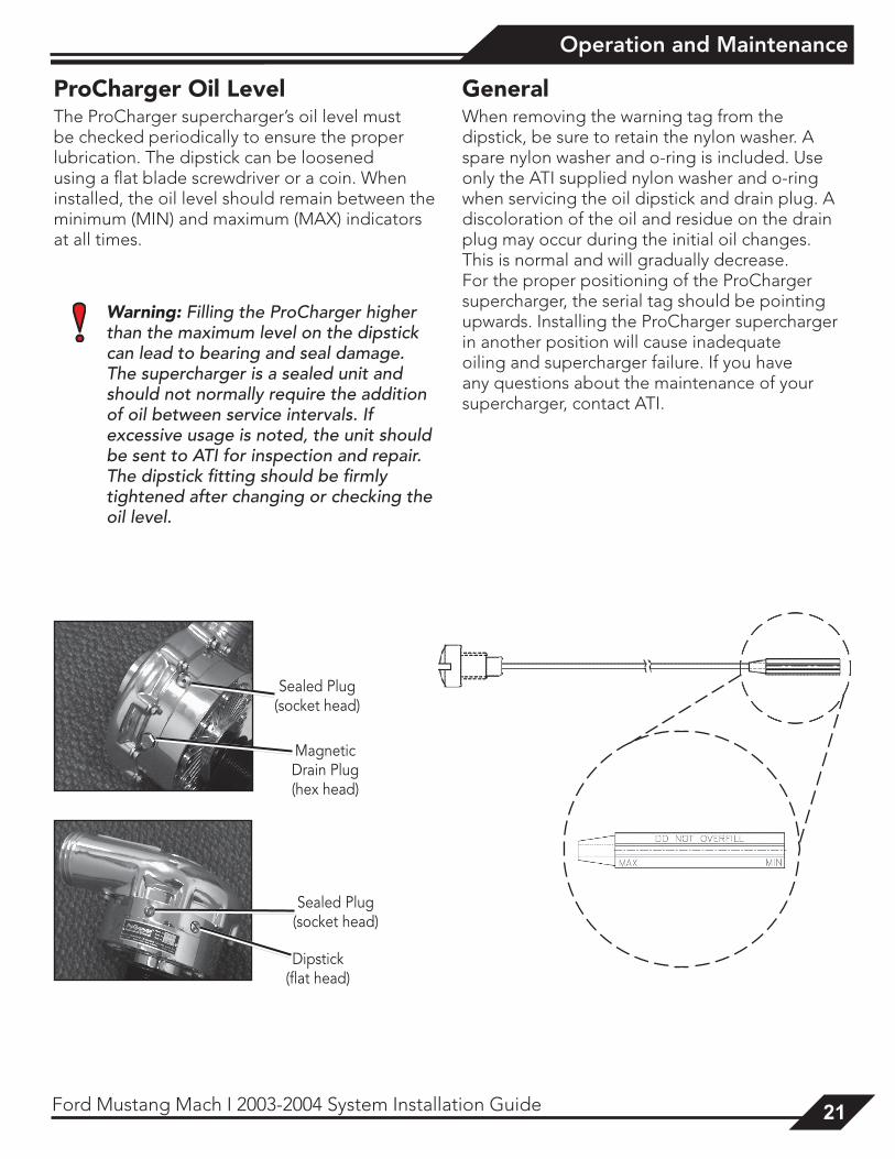
Magnetic Drain Plug (hex head)
Sealed Plug (socket head)
Dipstick (flat head)
Sealed Plug (socket head)
ProCharger Oil LevelThe ProCharger supercharger’s oil level must be checked periodically to ensure the proper lubrication. The dipstick can be loosened using a flat blade screwdriver or a coin. When installed, the oil level should remain between the minimum (MIN) and maximum (MAX) indicators at all times.
Warning: Filling the ProCharger higher than the maximum level on the dipstick can lead to bearing and seal damage. The supercharger is a sealed unit and should not normally require the addition of oil between service intervals. If excessive usage is noted, the unit should be sent to ATI for inspection and repair. The dipstick fitting should be firmly tightened after changing or checking the oil level.
GeneralWhen removing the warning tag from the dipstick, be sure to retain the nylon washer. A spare nylon washer and o-ring is included. Use only the ATI supplied nylon washer and o-ring when servicing the oil dipstick and drain plug. A discoloration of the oil and residue on the drain plug may occur during the initial oil changes. This is normal and will gradually decrease. For the proper positioning of the ProCharger supercharger, the serial tag should be pointing upwards. Installing the ProCharger supercharger in another position will cause inadequate oiling and supercharger failure. If you have any questions about the maintenance of your supercharger, contact ATI.
2222 Ford Mustang Mach I 2003-2004 System Installation Guide
Limited Warranty
limiTed warranTy
Accessible Technologies, Inc. (ATI) provides a limited twelve (12) month warranty on the ProCharger supercharger against defects in materials and workmanship unless otherwise specified. This limited warranty starts on the date of original purchase from your local dealer, or date of shipment from the factory. This limited warranty coverage is extended only to the original owner and excludes hoses, sleeves, and electronic components manufactured by other companies. IF THE SUPERCHARGER’S DRIVE RATIO IS ALTERED IN ANY WAY FROM THE FACTORY SETTING, WARRANTY COVERAGE IS VOID. USE OF ANY PULLEY NOT MANUFACTURED OR SUPPLIED BY ATI VOIDS ALL WARRANTY COVERAGE. ATI’s warranty obligations are limited to the terms below:
ATI agrees to honor a warranty claim at its sole discretion and only after inspection at the ATI factory. No warranty will be honored if any part of the product is found to have been improperly installed, tampered with, mishandled, or misused in any way. Disassembly of the ProCharger supercharger or removal of the ProCharger supercharger’s serial plate voids all warranties. Claims for freight damages should be directed to the freight company.
If ATI’s limited warranty applies, your product will be repaired or replaced at ATI’s discretion and shipped back. If the limited warranty does not apply, ATI will advise you of the specific reason, cost of the repair, and delivery time. After advising you of this information we will, at your option, either proceed with repairs or return your product to you in the state in which it was received. In either case the product will be shipped to you, insured at replacement value. Therefore, you will pay the return shipping and insurance charges if ATI’s limited warranty does not apply to your product.
THE WARRANTY AND REMEDIES SET FORTH ABOVE ARE EXCLUSIVE AND IN LIEU OF ALL OTHERS, ORAL OR WRITTEN, EXPRESS OR IMPLIED. THE DURATION OF ANY AND ALL WARRANTIES ON THE PRODUCTS DISCUSSED ARE LIMITED TO THE PERIOD IDENTIFIED ABOVE. ATI IS NOT RESPONSIBLE IN ANY EVENT FOR DIRECT, SPECIAL, INCIDENTAL OR CONSEQUENTIAL DAMAGES. No ATI dealer, agent, or employee is authorized to make any modification, extension, or addition to this warranty.
To obtain service under this warranty you must do the following during the warranty period:
Phone ATI (913-338-3086) and provide us with the following information:
- ProCharger supercharger serial number. - Vehicle year, make, model, engine modifications, and other modifications. - Description of perceived issue.
If a solution to your issue can not be found after the above phone consultation, you will be assigned a return authorization number (RMA). You must then properly package and ship your product, at your expense, to the ATI factory. The product should be carefully packaged in a rugged box.
Include the following information inside the box with your product:
- Copy of your original invoice or receipt. - Name, address, and daytime telephone number. - Return authorization number (RMA). - Vehicle year, make, model, engine modifications, and other modifications. - Description of perceived issue.
Clearly mark the warranty claim number on the top and one side of the box in characters at least 2” tall. Properly package the product and ship it, prepaid and insured for the retail value of the component(s) being returned, to the following address:
Accessible Technologies, 14801 West 114th Terrace, Lenexa, Kansas 66215
23Ford Mustang Mach I 2003-2004 System Installation Guide 23
ProCharger Extended Coverage
proCharGer exTended CoveraGe
The ProCharger Extended Coverage Program extends the ProCharger warranty coverage for an additional twenty-four (24) months, for a total of thirty-six (36) months or three years of coverage. This extended coverage applies to parts for the ProCharger supercharger head unit only and does not include other system components. With your extended coverage registration, you will receive two (2) additional boxes of ProCharger Supercharger oil.
Under the extended coverage program, Accessible Technologies, Inc. (ATI) will repair or replace any component within the supercharger head unit which is found to be defective. Only the supercharger head unit itself is included in the extended coverage.
Service under the extended coverage program is obtained through the same process as described in the Limited Warranty.
Race kits are not eligible for the ProCharger Extended Coverage Plan
To qualify for the ProCharger Extended Coverage:
• Only the original owner of the ProCharger supercharger is eligible.
• Completion of the Extended Coverage Registration Form is required, along with a $49 registration fee. This form must be completed in its entirety, and must be submitted along with payment within 30 days from the date of original purchase from your local dealer or date of shipment from the factory.
• Participants must have a ProCharger P-1SC, P-1SC-1, C1, or C2 supercharger head unit using the maximum warranted boost level. All terms and conditions within “The Limited Warranty” apply. Acts resulting in disqualification include but are not limited to the following:
- Disassembly or modification the ProCharger supercharger.
- Removal or attempted removal of the ProCharger drive pulley(s).
- Removal or attempted removal of the ProCharger supercharger serial number plate.
- Removal or attempted removal of the compressor housing or transmission case.
• Participants agree to properly maintain the ProCharger supercharger and provide proof of compliance with the following recommended maintenance:
- Change the ProCharger supercharger oil after the initial break-in period of 500 miles (automotive) or 15 hours (marine).
- Change the ProCharger supercharger oil every 6,000 miles after the initial break-in period.
- Use only the specified amount of ProCharger Supercharger oil in the ProCharger supercharger.
- Inspect and clean the magnetic drain plug at every ProCharger supercharger oil change.
- Check the ProCharger supercharger oil level frequently.
2424 Ford Mustang Mach I 2003-2004 System Installation Guide
Notes:
ProCharger Extended Coverage Program Registration Formcu
t al
ong
the
do
tted
line
cut
alo
ng t
he d
ott
ed li
ne
Name:_________________________________
Address:_______________________________
City:___________________________________
State:________________ Zip:____________
Daytime phone:_________________________
Evening phone:_________________________
E-mail:_________________________________
Age 18 - 24 25 - 34 35 - 44 45 - 54 55 and up
Income $15,000 - $29,000 $30,000 - $44,000 $45,000 - $69,000 $70,000 and up
What magazines do you read?
Car & Driver Car Craft Chevy High Performance Four Wheel and Off Road Hot Rod Motor Trend Muscle Mustangs and Fast Fords GM High-Tech Performance 5.0 Mustang Super Street Mustang Monthly Truck Trends Popular Hot Rodding Road & Track Super Chevy Truckin’ Street Truck
Date of Purchase:_______________________
Purchased From:_______________________
ProCharger Serial #:_____________________
Vehicle Year:___________________________
Vehicle Make:__________________________
Vehicle Model:_________________________
Please rank in order of importance starting with 1 being most important.
Which information sources most influenced your decision to purchase a ProCharger system?
___ Magazine advertising ___ Dealer recommendation ___ ProCharger Brochures ___ Witnessed performance on a car ___ Test drive ___ Magazine editorials ___ Friends ___ Conversations with ATI technicians ___ Web Site (please specify)___________ ___ Other (please specify)__________
What most influenced your decision to purchase a ProCharger system?
___ Reliability ___ Standard warranty ___ Extended coverage warranty ___ Performance ___ Quiet operation ___ Removability (ability to return car to stock) ___ Cost ___ Ease of Installation
Who installed your ProCharger system? Self Dealer Other ________________________ Have you own a forced induction system previously? Yes No If yes: Supercharger: Brand(s)_______________________ Vehicle(s)_____________________________
Turbocharger: Brand(s)_______________________ Vehicle(s)_____________________________
I have read and understand the policy for the ProCharger Extended Coverage Program. I have not and will not modify my ProCharger supercharger in any way during my participation in the extended coverage program. I have read and answered all questions on this form. I have enclosed my check for $49, payable to ATI, for enrolling my ProCharger supercharger (serial number indicated above) in the extended coverage program for an additional twenty-four (24) months beyond the standard limited warranty period of twelve (12) months.
Signature_____________________________________________ Date_____________________
Mail this completed registration form with a $49 check to ATI at: 14801 West 114th Terrace, Lenexa, KS 66215. If you have any questions, contact us at [email protected] or (913) 338-2886 8:30 AM - 5:30 PM CST, Monday - Friday.
Return this completed form and a $49 check within 30 days of original purchase.

this page intentionaly left blank

this page intentionaly left blank

Accessible Technologies, Inc. ©2007 ATI, All Rights Reserved
Part Number PMFL1A-001 Rev. C
Accessible Technologies, Inc. 14801 W. 114th Terrace
Lenexa, KS 66215 Phone: 913.338.2886
Fax: 913.338.2879 [email protected]
*PMFL1A-001*


![Mach number P w,test [bar] P model [bar] 1.8 -0.45 -0.20 0 ...ae342/18/lab2/lab2data.pdf · Mach 2.0 Snapshot . Mach 1.8 Snapshot . Mach 2.3 Snapshot Mach 2.2 Snapshot . P w,test](https://static.fdocuments.us/doc/165x107/5fb4e5220b26be1bae0aea08/mach-number-p-wtest-bar-p-model-bar-18-045-020-0-ae34218lab2-.jpg)