Mussel-inspired Polyglycerol Coatings for the Prevention ...
210
Mussel-inspired Polyglycerol Coatings for the Prevention of Biomaterial-related Fouling Dissertation for the acquisition of the academic degree of Doctor of Natural Sciences (Dr. rer. nat.) Submitted by Michaël Willem Kulka From Roermond (Netherlands) Institute for Organic Chemistry Department of Biology, Chemistry, Pharmacy Freie Universität Berlin 2020
Transcript of Mussel-inspired Polyglycerol Coatings for the Prevention ...

Mussel-inspired Polyglycerol Coatings for the
Prevention of Biomaterial-related Fouling
Dissertation for the acquisition of the academic degree of
Doctor of Natural Sciences (Dr. rer. nat.)
Submitted by
Michaël Willem Kulka
From Roermond (Netherlands)
Institute for Organic Chemistry
Department of Biology, Chemistry, Pharmacy
Freie Universität Berlin
2020

The following work has been performed under the supervision of Prof. Dr. Rainer Haag from April
2016 till June 2020, at the department of chemistry and biochemistry of the Freie Universität
Berlin. Parts of this thesis have been financially supported by collaborative research center
"Multivalence as chemical organizational and action principle" (SFB 765) which was funded by
the "Deutsche Forschungsgemeinschaft" (DFG). Furthermore, the work was financially supported
by the German Federal Ministry of Education and Research (BMBF) via the "KMU-innovativ"
program "GlycoVAD".
Hereby I declare that the following thesis was prepared autonomously and that no illegal
help was used. Contributions of others, e.g., content, quotes, or figures are indicated by referring
to the original work.
Berlin, 25.06.2020, __________________________ (Michaël Willem Kulka)
Direct Supervisor: Prof. Dr. Rainer Haag
Second Supervisor: Dr. Jens Dernedde
Date of Disputation: 25.06.2020

ACKNOWLEDGEMENTS
First, I would like to thank Prof. Dr. Rainer Haag for giving me the opportunity to conduct my
doctoral work in his research group at the department for chemistry and biochemistry of the Freie
Universität Berlin (FUB) (Berlin, Germany). Additionally, I would like to thank Prof. Dr. Michael
Schirner, Dr. Katharina Achazi, Chuanxiong Nie, Yannic Kerkhoff, and Elisa Quaas of the FUB,
and Dr. Jens Dernedde and Dr. Kim Silberreis of the Charité Universitätsmedizin (Berlin,
Germany), for their assistance in the biological experiments that were conducted in my work.
Furthermore, I would like to thank PD Dr. Kai Licha of the company FEW Chemicals GmbH
(Bitterfeld-Wolfen, Germany) for his support considering organic synthesis. Besides, I would like
to thank Dr. Luis Cuellar Camacho (FUB) for teaching me how to execute atomic force
microscopy, and Anke Schindler (FUB) for teaching me how to perform scanning electron
microscopy. I would also like to express my gratitude to Prof. Dr.-Ing. Klaus Affeld († 2019), PD
Dr.-Ing. Ulrich Kertzscher, Tim Bierewirtz, Felix Hehnen, and Sarah Smatty of the biofluid
mechanics lab at the Charité medical university (Berlin, Germany), who heavily supported this
work with their expertise in biofluid mechanics. I also wish to thank my cooperation partners Dr.
Lars I. Dahms, Dr. Lena Kaufmann, Sebastian Friedrich, and Valentin Kunz at Berlin Heart GmbH
(Berlin, Germany), for supporting this work with their expertise in ventricular assist devices. I
would also like to convey my gratitude to Prof. Dr. Ingo Grunwald of the City University of
Applied Sciences Bremen (Bremen, Germany) and Dr. Dirk Salz of the Fraunhofer Institute for
Manufacturing Technology and Advanced Materials (Bremen, Germany) for their technical
support in the physical vapor deposition of titanium dioxide. Furthermore, I would like to thank
Dr. Özlem Özcan, Dr. Wolgang Unger, Dr. Jörg Radnik, Nina Wurzler, and Jörg M. Stockmann
of the Federal Institute for Materials Research and Testing (BAM) (Berlin, Germany) for their
support in the streaming potential and X-ray photoelectron spectroscopy measurements.
Additionally, I would like to thank Dr. Ievgen S. Donskyi and Philip Nickl of the FUB for their
help in the fitting of all X-ray photo electron spectroscopy spectra. I would also like to
acknowledge the technical assistance of the core facility BioSupraMol (FUB), which is financially
supported by the Deutsche Forschungsgemeinschaft (DFG). Furthermore, I would like to thank
the collaborative research center 765 (SFB 765) and the German Federal Ministry for Education
and Research (BMBF) for their financial contributions to this doctoral work. I also wish to thank

Dr. Wiebke Fischer, Eike Ziegler, Lydia Alnajjar, and Katharina Tebel, for dealing with the
bureaucratic and financial matters at the FUB. Additionally, I would like to thank Dr. Pam
Winchester for proofreading the thesis and all the manuscripts.
I also thank my colleagues from the Haag group, with whom I had great discussions about
work, as well as about private interests. Besides, I would like to thank all my non-work-related
friends in both Berlin and the Netherlands, who always supported me throughout my doctoral
work. Finally, my thanks go out to my family, especially my parents, sister, and grandmother who
are always there for me whenever I need them.

CONTENT
1. INTRODUCTION................................................................................................................. 1
2. THEORETICAL BACKGROUND .................................................................................... 3
2.1. Biomaterial-induced Thrombosis ..................................................................................... 3
2.1.1. Platelet Activation and Fibrinogen ........................................................................... 4
2.1.2. The Intrinsic Pathway of Blood Coagulation ............................................................ 7
2.1.3. Activation of Leukocytes .......................................................................................... 8
2.1.4. Complement System Activation ............................................................................... 8
2.1.5. Other Thrombosis-inducing Factors ......................................................................... 9
2.1.6. ISO Norms for Blood-contacting Materials .............................................................. 9
2.2. Thrombus Formation Under High Shear Conditions ..................................................... 10
2.2.1. Shear Factors ........................................................................................................... 11
2.2.2. The vWF and Shear ................................................................................................ 12
3.3.3. Assessing Shear-Thrombosis Relations .................................................................. 13
2.3. Bioactive Antithrombogenic Surfaces ........................................................................... 17
2.4. Bioinert Polymer Coatings ............................................................................................. 18
2.4.1. Hydrophilic Antifouling Coatings .......................................................................... 18
2.4.2. Zwitterionic Antifouling Coatings .......................................................................... 20
2.4.3. Superhydrophobic Antifouling Coatings ................................................................ 22
2.5. Alternative Antithrombogenic Surfaces ......................................................................... 24
2.6. Mussel-inspired Surface Chemistry ............................................................................... 25
2.6.1. Mussel Adhesion ..................................................................................................... 25
2.6.2. Polydopamine and Catechol Chemistry .................................................................. 28
2.6.3. Mussel-inspired Polymeric Coatings ...................................................................... 29
2.6.4. Mussel-inspired Dendritic Polyglycerol ................................................................. 30
2.7. Functional Mussel-inspired Surface Coatings................................................................ 31
2.7.1. Mussel-inspired Antithrombogenic Surfaces.......................................................... 31
2.7.2. Mussel-inspired Hydrophilic Antifouling Surfaces ................................................ 32
2.7.3. Mussel-inspired Superhydrophobic/Superamphiphobic Surfaces .......................... 36
3. SCIENTIFIC GOALS ........................................................................................................ 37
4. PUBLICATIONS ................................................................................................................ 39
4.1. Mussel-inspired Multivalent Linear Polyglycerol Coatings Outperform Monovalent
Polyethylene Glycol Coatings in Antifouling Surface Properties ............................................ 39
4.2. The Application of Dual-layer, Mussel-inspired, Antifouling Polyglycerol-based
Coatings in Ventricular Assist Devices .................................................................................... 0
4.3. Surface-initiated Grafting of Dendritic Polyglycerol from Mussel-inspired Adhesion
Layers for the Creation of Biocompatible Cell-repelling Coatings ........................................
5. SUMMARY AND CONCLUSIONS ...............................................................................
OUTLOOK ........................................................................................................................
KURZZUSAMMENFASSUNG.......................................................................................
8. ABBREVIATION LIST ...................................................................................................
9. LITERATURE ..................................................................................................................
10. PUBLICATION LIST ......................................................................................................
11. CURRICULUM VITAE...................................................................................................

1. INTRODUCTIONCardiovascular diseases (CVDs) are the leading cause of mortality and are responsible for 3.9
million death per year in Europe as a whole (i.e., 45% of all deaths).1 The application of
ventricular assist devices (VADs) is often considered a last resort treatment and is commonly
used as bridging therapy for severe CVD patients awaiting heart transplantations. VADs are
electromechanical devices which support cardiac circulation or fully replace the function of a
failing heart (Figure 1). However, users of VADs suffer from complications resulting from
hemolysis and shear-induced thrombosis.2 To overcome the issues considering VAD-
associated thrombosis, there is a need for new durable surface coatings, which prevent the
formation of shear-induced thrombi on the blood-contacting surfaces in VADs. However, this
is challenging because of the wide variety of wall shear rates commonly encountered in VADs,
which lead to biomaterial-induced thrombosis through various mechanisms.3 Additionally, the
potential wear effect of high wall shears can significantly compromise the stability of the
coatings.
State-of-the-art techniques for preventing biomaterial-associated thrombosis either rely
on bioactive coatings that interact with specific blood-components,4 or on coatings that prevent
the adhesion of protein and cells (i.e., organic or inorganic bioinert coatings).5-8 Over the last
decades, surface functionalization with polymeric coatings has become an interesting approach
to introduce tailor-made properties (e.g., antithrombogenic bioactive or bioinert properties) to
a material surface. Traditionally, thiol and siloxane chemistries are applied to modify noble
metals and hydroxylated surfaces, respectively.9-10 Alternatively, methods such as Langmuir-
Blodgett deposition,11 layer-by-layer (LbL) assembly,12 irradiation-mediated grafting,13-14 and
electrostatic or hydrophobic adsorption are used for the effective immobilization of functional
polymers on a surface.15-16 However, most of these methods require specific chemical and/or
physical properties of the substrate or the use of complex machinery, thus limiting their
application. Therefore, there is a need for novel substrate-independent coating methods, which
can extend the application of polymeric coatings to a broad range of substrate materials.
1

Figure 1. (A) The picture shows an INCOR® VAD by Berlin Heart GmbH (Berlin, Germany),
which reaches rotation numbers between 5,000-10,000 rotations per minute (2-9 lmin-1),
leading to shear strain rates up to maximum 200,000 s-1. The production of this specific model
of VAD was terminated at the end of 2018. (B) Examples of thrombosis in the HeartMate II
VAD system by Abbott laboratories (Abbott Park, Illinois, USA). The top image shows a pure
fibrin clot resulting from high shear. The bottom images show a fibrin and blood clot. This
figure was reproduced with permission from ref. 17 Copyright © 2014, Elsevier. (C) An in
silico modulation of the shear rates within the model VAD. The red areas represent the areas
with high shear, whereas the yellow, green, and blue areas represent the areas with lower wall
shear stress. The blue top part represents the flow straightener that is used for fixation of the
rotor. This figure was reproduced with permission from ref. 18 Copyright © 2016, Nature.
To achieve universal, stable, and substrate-independent coating behavior, the anchoring
interactions between a polymeric coating material and a surface must be well designed. For
instance, as no anchor group will be reactive to all types of substrates, the formation of
chemical bonds between anchor groups of the polymer and functional groups of the substrate
is not always preferred. The use of unspecific non-covalent interactions, such as electrostatic
interactions, hydrogen bonds, hydrophobic interactions, and van der Waals interactions, is a
promising alternative for the creation of substrate-independent coating behavior, because these
interactions have proven to be strong enough to effectively tether polymer coatings to the
2

surface. Examples of non-covalently attached functional polymer films include the creation of
electrodes coated with hemoglobin-octadecylamine films via Langmuir-Blodgett deposition,19
the creation of cell adhesive substrates via the formation of polyelectrolyte films,12 and the
creation of protein repelling surfaces via the non-covalent adsorption of amphiphilic polymers
to hydrophobic surfaces.16 The coating stability can be enhanced by chemical crosslinking,
amplifying the stabilizing intra-layer interactions.20 Recently, mussel-inspired surface
chemistry has been increasingly applied to the substrate-independent modification of
biomaterials, as will be discussed in more detail later in this thesis.21-22 Consequently, a
multitude of antifouling and bioactive surfaces for the prevention of biomaterial-associated
fouling and thrombosis have been developed.6, 23-27 Most of these studies have ignored the
critical role of shear forces in the substrate-induced formation of surface blood clots.
The aim of this doctoral thesis was to use mussel-inspired polymeric surface coatings
to introduce antifouling and antithrombogenic surface properties to medically relevant titanium
dioxide (TiO2) surfaces and other blood contact materials. Furthermore, the focus of this thesis
was on investigating the relation between wall shear stress and biomaterial-associated
thrombosis (i.e., the antithrombotic effectiveness of the developed materials under low and
high shear conditions).
2. THEORETICAL BACKGROUND
2.1. Biomaterial-induced ThrombosisThe use of biomaterials is essential in many medical treatments, such as hemodialysis,28 bone
and joint substitution,29 and in vascular grafts.30 When a biomaterial is exposed to a biological
liquid (e.g., whole blood or lymph), proteins rapidly adhere to the surface in a dynamic process.
The composition and development of this protein layer depend on the physical and chemical
characteristics of the biomaterial, and determine the fate of the biomaterial in a biological
environment. In blood-contacting biomaterials, the protein layer mediates the adhesion and
activation of platelets and leukocytes, that adhere to the protein-coated surface via specific
receptors. The protein layer can also develop over time into surface-bound protein complexes
that trigger coagulation- or complement-activating reactions.31
3

2.1.1. Platelet Activation and Fibrinogen
Blood platelets are abundantly present in the blood and can circulate for 1-7 days in a quiescent
state under physiological conditions.32 Platelets are 1-3 μm sized lens-shaped fragments of
cytoplasm that stop the bleeding of damaged blood vessels during hemostasis by clumping and
clotting.32-33 When a blood vessel is damaged, the endothelium of the vessel is interrupted and
the underlaying collagen is exposed to the circulating platelets. The platelets then rapidly bind
to the exposed collagen matrix, initiating the primary hemostasis.34 The exposure of a
biomaterial to whole blood can also result in the adhesion and activation of blood platelets
(Figure 2), potentially leading to adverse biomaterial-induced thrombosis. Therefore, testing
the platelet adhesive and activating properties of a blood-contacting biomaterial is important.
Upon blood exposure, plasma proteins, including albumin, fibrinogen, fibronectin, vitronectin,
and the von Willebrand factor (vWF) adhere to the biomaterial surface within seconds to
minutes.35 Fibrinogen has been identified as the most important protein in biomaterial-induced
platelet adhesion,36 and as little as 7 ng/cm2 of immobilized fibrinogen has been reported to
effectively induce platelet adhesion.37 However, native fibrinogen does not mediate platelet
activation in fluid blood, which indicates that platelet adhesion to fibrinogen requires
biomaterial-induced configurational changes of fibrinogen. Besides fibrinogen, also
fibronectin, vWF, and vitronectin can mediate the adhesion and activation of blood platelets.
The adhesion of platelets to the surface-bound protein is mediated via specific cell membrane
receptors, such as glycoprotein IIb and IIIa (GPIIb and GPIIIa, respectively).38
Figure 2. Various stages in the transformation of a human blood platelet, going from its
inactive spheroidal form (A) to its activated fully spread form (H). In mammals, thrombocytes
do not have a cell nucleus, but in other animal classes (such as birds and amphibians)
thrombocytes can be found as intact mononuclear cells.39 On a healthy endothelial cell
4

monolayer, platelet adhesion and activation is prevented by antithrombogenic properties of
nitric oxide (NO) and prostaglandin I2, which are both released from the endothelial surface.32
This figure was reproduced with permission from ref. 40 Copyright © 1979, Rockefeller
University Press.
Even though the specific mechanisms of the binding of platelets to fibrinogen remain
to be elucidated, the influence of the amount of adherent fibrinogen and albumin on the blood-
compatibility of biomaterials has been previously well investigated.41-42 In contrast to
fibrinogen, albumin is generally considered inert toward platelet adhesion and activation.36
Therefore, the development of surfaces, which selectively adsorb albumin while rejecting
fibrinogen has been proposed as an effective way to prevent biomaterial-induced platelet
adhesion.43-44 Besides the amount of protein, there is growing evidence that the conformation
of the adherent fibrinogen influences biomaterial-induced platelet adhesion.35, 45 For instance,
Sivaraman et al. have observed that platelet adhesion is strongly correlated with the degree of
adsorption-induced unfolding of fibrinogen, whereas no correlation to the amount of adsorbed
fibrinogen was found.45 Their study also indicated that –OH terminated self-assembled
monolayers (SAMs) induce only little degradation of the secondary structure of native
fibrinogen, whereas –CH3 terminated SAMs clearly lead to concentration-dependent, substrate-
induced changes. Interestingly, the changes in the secondary structure were pronounced more
strongly at lower fibrinogen concentrations, explained by the higher surface area available per
fibrinogen strand. At the low concentrations, the fibrinogen strand degraded as a result of the
hydrophobic effect, after adhering to the surface in its native form. In contrast, at high
concentrations the fibrinogen strands quickly saturated the surface, and the proteins were not
able to unfold resulting from the lack of free space on the surface.45 Several other studies have
also focused on the relation between the conformation of fibrinogen and platelet
adhesion/activation.35, 46 Although this relation is not yet fully understood, the conformation of
fibrinogen is now generally accepted as an important parameter in biomaterial-induced platelet
adhesion.
The adhesion and activation of platelets are important in natural coagulation, which is
the process in which liquid blood turns into a gel (i.e., forms a blood clot), leading to the
cessation of blood loss from a damaged blood vessel. Coagulation includes the adhesion,
activation, and aggregation of platelets (i.e., primary hemostasis), as well as the formation and
5

maturation of a fibrin film (i.e., secondary hemostasis).39 The coagulation cascade can be
divided in two pathways, an intrinsic pathway (or contact activated pathway) and an extrinsic
pathway (or tissue-factor pathway) (Figure 3)39, 47 that both finally result in the activation of
thrombin, transforming soluble fibrinogen into the insoluble fibrin strands.39 Both pathways
consist of series of soluble zymogens (i.e., inactive precursors of enzymes), which activate
each other in a cascade-like manner. The extrinsic pathway is activated when coagulation factor
VII (FVII) is exposed to tissue factor (TF), which is found in the tissues of the subendothelium
(in natural coagulation TF is released from the subendothelium upon vessel damage).39 The
resulting fibrin formation strengthens the platelet plug, that simultaneously forms at the site of
endothelial damage.39 The intrinsic pathway involves a series of protein cofactors and enzymes,
which interact in reactions that take place on membrane surfaces. The intrinsic pathway will
be discussed in more detail in the next chapter of this thesis.
Figure 3. A schematic representation of the intrinsic and extrinsic pathways of the coagulation
cascade. This figure was reproduced with permission from ref. 48 Copyright © 2019, Royal
Society of Chemistry.
6
Multiple scientific studies have shown that platelet adhesion, activation, and
aggregation are intertwined with the two pathways of the coagulation cascade. For instance,
platelets can induce the activation of coagulation factor XII (FXII), hereby triggering the
intrinsic pathway of the coagulation cascade,49 and vice versa, thrombin can also activate the
platelets.50
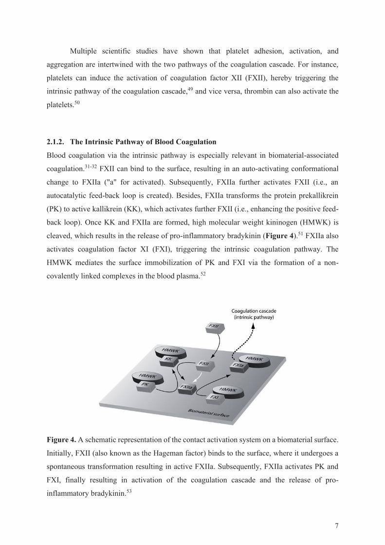
2.1.2. The Intrinsic Pathway of Blood Coagulation
Blood coagulation via the intrinsic pathway is especially relevant in biomaterial-associated
coagulation.31-32 FXII can bind to the surface, resulting in an auto-activating conformational
change to FXIIa ("a" for activated). Subsequently, FXIIa further activates FXII (i.e., an
autocatalytic feed-back loop is created). Besides, FXIIa transforms the protein prekallikrein
(PK) to active kallikrein (KK), which activates further FXII (i.e., enhancing the positive feed-
back loop). Once KK and FXIIa are formed, high molecular weight kininogen (HMWK) is
cleaved, which results in the release of pro-inflammatory bradykinin (Figure 4).51 FXIIa also
activates coagulation factor XI (FXI), triggering the intrinsic coagulation pathway. The
HMWK mediates the surface immobilization of PK and FXI via the formation of a non-
covalently linked complexes in the blood plasma.52
Figure 4. A schematic representation of the contact activation system on a biomaterial surface.
Initially, FXII (also known as the Hageman factor) binds to the surface, where it undergoes a
spontaneous transformation resulting in active FXIIa. Subsequently, FXIIa activates PK and
FXI, finally resulting in activation of the coagulation cascade and the release of pro-
inflammatory bradykinin.53
7

The intrinsic coagulation pathway is activated by exogenous negatively charged
surfaces, such as glass,54 silica,55 dextran sulfate,56-57 kaolin,58 and nanoparticles.59 More recent
studies have also identified endogenous activators, such as polyphosphates,60 collagen,61 and
misfolded protein aggregates.62 Besides, physiologically negatively charged surfaces, such as
cell membranes (i.e., both eukaryotic and prokaryotic) and virus particles, might also provide
a sufficient negative charge for the activation of the contact-activated system.63
2.1.3. Activation of Leukocytes
Neutrophils (i.e., the most prominent class of leukocytes) can adhere to fibrinogen via
transmembrane receptors.64-65 Additionally, adherent platelets can promote the adhesion of
neutrophils via receptor-mediated binding.66 Upon surface immobilization, neutrophils
promote the production of TF,67-68 that activates the intrinsic pathways of the coagulation
cascade. Furthermore, neutrophils promote platelet activation by the release of platelet
activating substances, such as platelet-activating factor, interleukins, and tumor necrosis factor
from their stored granules.31 Vice versa, it has long been recognized that platelets can mediate
the release of TF from neutrophils, thus indirectly coupling platelet adhesion/activation to the
extrinsic coagulation pathway.69
2.1.4. Complement System Activation
The contact of artificial surfaces with blood leads to the immediate adsorption of serum protein
onto the surface. Initially, more abundant and mobile protein (i.e., albumin, globulin,
fibrinogen, and fibronectin) will adsorb to the surface.31 Subsequently, these protein are
replaced by less mobile proteins with higher affinity to the surface (such as FXII and HMWK)
in a kinetic process called the Vroman effect.70 Especially the complement protein C3 (and its
spontaneously formed hydrolysis products) binds well to foreign surfaces, leading to activation
of the complement system.71 The complement system is a part of the innate immune system,
which enhances the ability of antibodies and phagocytic cells to clear microbes and damaged
cells from the host. The complement system consists of more than 30 serum proteins.72 Some
of them can be serially activated and participate in cascade reactions that finally lead to
chemotaxis (i.e., inducing the movement of organisms/cells via chemical stimuli) and
opsonizing reactions (i.e., reactions that enhance phagocytosis).73 Furthermore, the
complement system promotes inflammation and attacks the cell membranes of pathogen cells
8

via the formation of the so-called membrane attack complex (MAC).74 The degree in which a
biomaterial triggers the complement system is dependent on the chemical and physical
properties of the biomaterial’s surface. However, an earlier study has shown that hydrophobic
surfaces are more likely to promote complement system activation than hydrophilic surfaces.75
Especially the complement factors C5a and C3a function as potent leukocyte chemo-
attractants, which enhance leukocyte adhesion and activation, resulting in the release of
coagulation-activating TF. This indirectly links the complement system to the extrinsic
coagulation pathway (Figure 5).31
2.1.5. Other Thrombosis-inducing Factors
The implantation of a biomaterial can also lead to thrombosis unrelated to the properties of the
biomaterial, i.e., through altered blood-flow parameters and turbulent flow.76-77 Additionally,
red blood cells can adhere to biomaterial surfaces in a passive process, where they can promote
platelet activation by the release of adenosine diphosphate (ADP).31 Besides, ADP and
hemoglobin can be released upon rupture of the red blood cells in a process called hemolysis.
The released hemoglobin acts as a scavenger molecule for NO, which effectively enhances
platelet activation by overturning the inhibitory effect of NO on platelet activation.78-79
2.1.6. ISO Norms for Blood-contacting Materials
New commercial blood-contacting biomaterials are only allowed to the market when they have
been tested for their interaction with the blood components according to a given set of tests.
The International Organization for Standardization (ISO) (i.e., the international organization
responsible for the creation of production norms) has summarized a selection of required
testing methods (including their required design) for blood-contacting biomaterials in their
norm ISO 10993. Although some scientific works have been conducted according to this ISO-
norm,80-84 the use of ISO 10993 is fairly uncommon in the development of novel biomaterials.
9
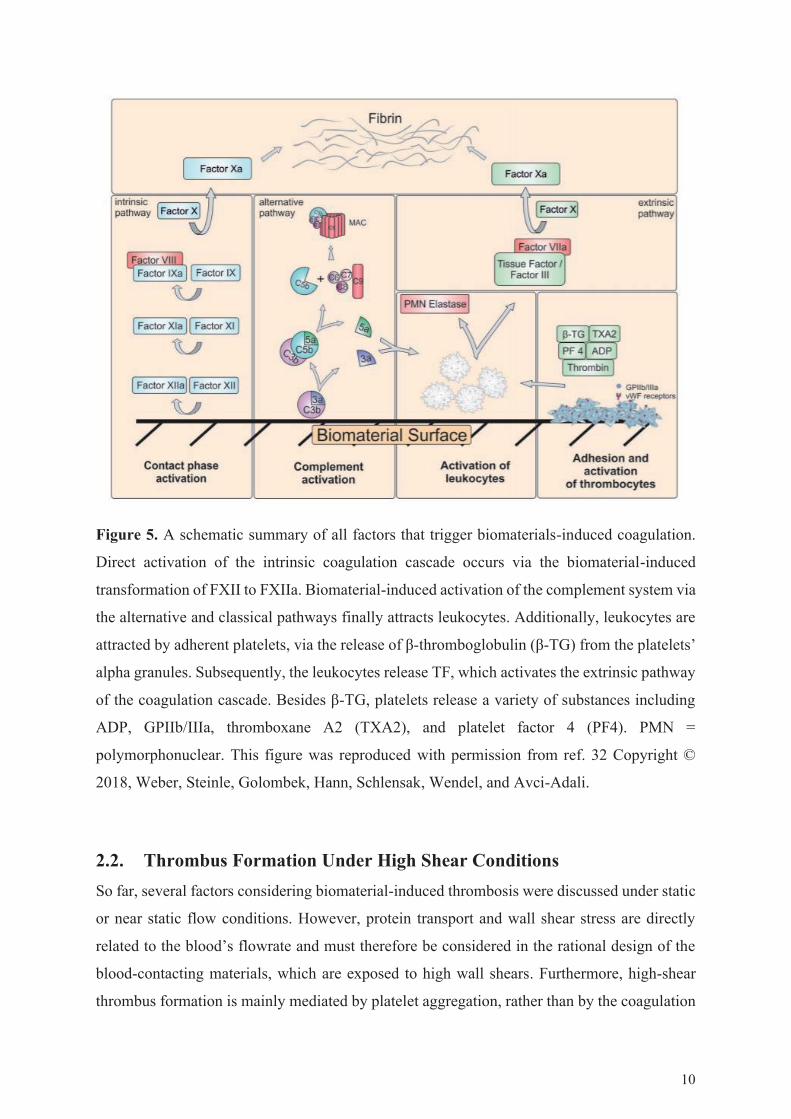
Figure 5. A schematic summary of all factors that trigger biomaterials-induced coagulation.
Direct activation of the intrinsic coagulation cascade occurs via the biomaterial-induced
transformation of FXII to FXIIa. Biomaterial-induced activation of the complement system via
the alternative and classical pathways finally attracts leukocytes. Additionally, leukocytes are
attracted by adherent platelets, via the release of β-thromboglobulin (β-TG) from the platelets’
alpha granules. Subsequently, the leukocytes release TF, which activates the extrinsic pathway
of the coagulation cascade. Besides β-TG, platelets release a variety of substances including
ADP, GPIIb/IIIa, thromboxane A2 (TXA2), and platelet factor 4 (PF4). PMN =
polymorphonuclear. This figure was reproduced with permission from ref. 32 Copyright ©
2018, Weber, Steinle, Golombek, Hann, Schlensak, Wendel, and Avci-Adali.
2.2. Thrombus Formation Under High Shear ConditionsSo far, several factors considering biomaterial-induced thrombosis were discussed under static
or near static flow conditions. However, protein transport and wall shear stress are directly
related to the blood’s flowrate and must therefore be considered in the rational design of the
blood-contacting materials, which are exposed to high wall shears. Furthermore, high-shear
thrombus formation is mainly mediated by platelet aggregation, rather than by the coagulation
10

cascade.85 The following sections will highlight the role of shear in biomaterial-induced
thrombosis.
2.2.1. Shear Factors
Until now, the role of platelets, the complement system, leukocytes, and the coagulation
cascade in biomaterial-induced thrombosis has been discussed. However, the coagulation
cascade mainly dominates thrombus formation only at low shear rates (i.e., at shear rates < 50
s-1), where it causes the formation of erythrocyte-rich thrombi, appearing as red blood clots. In
contrast, at high shear rates (i.e., at shear rates > 5,000 s-1) thrombus formation is mainly
mediated via platelet aggregation, leading to the formation of white blood clots (Figure 1).86
Ex vivo and in vitro experiments have shown that high-shear thrombotic occlusion on
biomaterials is a three-phase process (Figure 6).87-88 In the first phase, platelets adhere to a
non-endothelial surface. The first phase shows only limited thrombus growth and is therefore
called the lag phase. Lag times can vary from 175 till 300 seconds for the initial shear rates of
500-5,000 s-1.89 The lag time is thought to represent the time needed for the deposition of
plasma protein on the surface, which is required for subsequent platelet adhesion.90
Additionally, the lag time includes the time needed for the gathering of a sufficient amount of
non-activated platelets (i.e., the time prior to the shear activation of the platelets). In the second
phase, the thrombus grows rapidly, which leads to the formation of the bulk of the occlusive
thrombus. In this phase, the thrombus can grow up to 60 times faster than in the initial phase,
depending on the magnitude of the applied shear rate.91 The final third phase involves
asymptotic coagulation thrombus growth, potentially leading to full occlusion of a blood
vessel.
11

Figure 6. (A) A graphical representation of the thrombus volume in all three phases This figure
was reproduced with permission from ref. 83 Copyright © 2015, Elsevier. (B) A graphical
representation of the thrombus growth rate in the second phase. This figure was reproduced
with permission from ref. 92 Copyright © 2016, Springer.
The first two phases depend on the shear rate in different manners. The duration of the
first phase decreases with increasing shear, resulting from the increased transportation of
protein to the surface.93 Furthermore, increased shear leads to enhanced vWF activation and
the increased mural activation of platelets.94-95 The second phase shows a shear-dependent
maximum around 25,000 s-1. Nevertheless, thrombus formation can still occur at shear rates >
100,000 s-1.85 For rapid thrombus growth to occur, the blood constituents first need to reach
the vessel wall or growing thrombus. Under flow, the presence of red blood cells and increased
shear rates enhance the mass transport of whole blood in a phenomenon called enhanced
diffusivity.93, 96 This leads to an enhanced diffusivity of large proteins and furthermore
enhances the platelet deposition rate, potentially contributing to rapid thrombus growth.
Additionally, platelets migrate to the vessel wall in flowing blood, which can significantly
enhance the concentration of near-wall platelets and thereby increase the risk of thrombus.97
2.2.2. The vWF and Shear
The vWF is a large multimeric glycoprotein that is found in platelet α-granules, the blood
plasma, and in the subendothelial connective tissue.98 Under high shear conditions, platelet
adhesion is mediated by vWF rather than by fibrinogen (Figure 7).99 At shear rates > 5,000
s-1, the vWF undergoes a conformational change, leading to the exposure of additional
12

collagen- and platelet-binding sites (Figure 8).94 When vWF is bound to the surface, it can
bind inactivated platelets at shear rates > 10,000 s-1 in the presence of soluble vWF.100
Additionally, the vWF forms long net-like structures under shear rates > 25,000 s-1.101
Furthermore, a previous study showed that thrombus formation was inhibited under high shear,
when the vWF was diluted by 90%.85 In contrast, thrombus formation continued in a blood
analogous solution containing only 10% of the physiological platelet count, when having
normal concentrations of vWF.85 The combined results clearly illustrated the critical role of the
vWF in coagulation. Therefore, it is important to prevent unspecific adhesion of the vWF to
blood-contacting biomaterials, especially when these materials are experiencing high shear
conditions (e.g., as in case of VADs).
3.3.3. Assessing Shear-Thrombosis Relations
As earlier discussed, shear plays an important role in (biomaterial-induced) thrombosis. Under
both healthy and pathological conditions, a wide variety of shear rates is observed in the
circulatory system.3 Therefore, understanding the influence of shear on biomaterial-induced
thrombosis is essential when developing blood-contacting biomaterials. In vitro methods for
studying the relation between shear and biomaterial-induced thrombosis can be divided in static
blood incubation models, agitated blood incubation models, and shear flow models.32 In the
static blood incubation models, the biomaterial is incubated with whole blood or platelet-rich
plasma (PRP) without flow conditions,102 which can quickly deliver information about the
intrinsic thrombogenicity of the surface in the absence of shear. However, the static models
provide little information about the general hemocompatibility of a biomaterial and suffer from
cell sedimentation and platelet activation, resulting from protein aggregate formation at the air-
blood interface.103 Agitated blood incubation models commonly utilize a flat incubation
chamber with the top and bottom faces made of the biomaterial of interest. The incubation
chamber is subsequently filled with blood and incubated on a shaker or overhead rotator
without directed flow.104 The incubation chamber can also be rotated, preventing blood
component or testing material sedimentation.105 A wide variety of shear models have been
developed, including tubular systems, such as the chandler loop and the roller pomp closed
loop,106-107 flat-plate flow chambers,108 and parallel plate-and-cone platelet viscometers.109
Furthermore, methods which utilize directed (microfluidic) flow channels for the
characterization of platelet adhesion to biomaterial surfaces have been described in
13

literature.110 However, these have limited diagnostic value, because of the constant shear
conditions.
Figure 7. A schematic representation of thrombus formation under high shear conditions. (A)
At high shear, the vWF unfolds and adheres to collagen of the damaged endothelium (e.g., as
a result of a ruptured atherosclerotic plaque) or to the biomaterial’s surface. (B) Platelets
migrate to the surface and (C) the inactivated platelets subsequently adhere to the surface-
bound vWF. (D) The platelet activation leads to the release of further vWF from the platelets
α granules, promoting further adhesion. (E, F) Additional vWF bind to mural platelets and lead
to further platelet aggregation. (G) Finally, a large-scale thrombus (light blue) forms on the
exposed collagen or biomaterial’s surface. RBC = red blood cells. This figure was reproduced
with permission from ref. 85 Copyright © 2015, Elsevier.
14

Figure 8. Unfolding of the vWF under varying shear rates, monitored by fluorescence
microscopy. This figure was reproduced with permission from ref. 94 Copyright © 2007,
National Academy of Sciences, U.S.A.
The use of stagnation point flow chambers has become prominent in the field of bio-
fluid mechanics, in order to overcome the problems associated with the other model types.111-
114 Stagnation point flow models utilize a laminar flow in combination with radial spreading of
the blood in customized flow chambers, resulting in radius-dependent wall shear rates. As a
result, platelet adhesion can be investigated under a wide variety of wall shear rates in a single
measurement. Affeld et al. developed a stagnation point flow model that was capable of
visualizing and quantifying platelet adhesion at shear rates 0-180 s-1 in a single measurement
(Figure 9).111-114 The model utilized a laminar flow module and a custom-made flow chamber
combined with an inverted fluorescence microscope and whole blood containing fluorescently
labeled platelets.112 The advantage of this model was the modular buildup of the custom flow-
chamber, allowing for the placement of polymer-coated substrates (Figure 10). Furthermore,
physical vapor deposition techniques could be applied to functionalize the glass substrates with
metallic coatings of choice, given that the coated metal layer remained transparent. As a result,
15

the adhesion of platelets to a broad range of materials and polymeric coatings could easily be
studied, utilizing the stagnation point flow model.
Surprisingly, the application of flow models with a broad spectrum of shear rates
remains fairly uncommon in the field of blood-contacting biomaterials, where
hemocompatibility and biocompatibility are still often considered under static conditions.6, 115-
119 However, as biomaterial-induced thrombosis is strongly linked to shear stress, there is a
need for the use of more advanced shear models that further help to improve blood-contacting
biomaterials.
Figure 9. (A) A schematic representation of the wall shear in the stagnation point flow model
developed by Affeld et al. The red color represents the areas with high shear, whereas blue
represents the areas with low shear. (B) A schematic representation of the laminar flow within
the flow chamber. (C) A graphical representation of the wall shear rate within the flow chamber
at 20 mlh-1 (blue) and at 40 mlh-1 (green). This figure was reproduced with permission from
ref. 120 Copyright © 2016, American Vacuum Society.
16
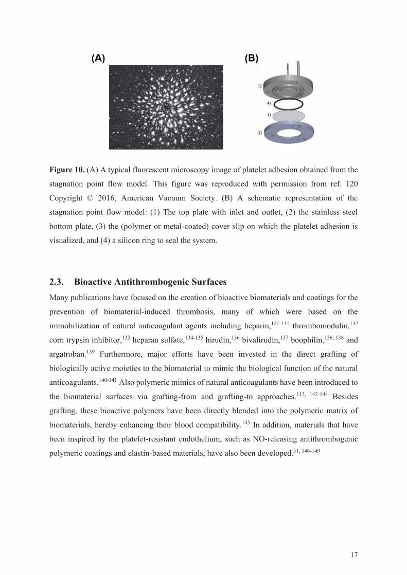
Figure 10. (A) A typical fluorescent microscopy image of platelet adhesion obtained from the
stagnation point flow model. This figure was reproduced with permission from ref. 120
Copyright © 2016, American Vacuum Society. (B) A schematic representation of the
stagnation point flow model: (1) The top plate with inlet and outlet, (2) the stainless steel
bottom plate, (3) the (polymer or metal-coated) cover slip on which the platelet adhesion is
visualized, and (4) a silicon ring to seal the system.
2.3. Bioactive Antithrombogenic SurfacesMany publications have focused on the creation of bioactive biomaterials and coatings for the
prevention of biomaterial-induced thrombosis, many of which were based on the
immobilization of natural anticoagulant agents including heparin,121-131 thrombomodulin,132
corn trypsin inhibitor,133 heparan sulfate,134-135 hirudin,136 bivalirudin,137 boophilin,136, 138 and
argatroban.139 Furthermore, major efforts have been invested in the direct grafting of
biologically active moieties to the biomaterial to mimic the biological function of the natural
anticoagulants.140-141 Also polymeric mimics of natural anticoagulants have been introduced to
the biomaterial surfaces via grafting-from and grafting-to approaches.115, 142-144 Besides
grafting, these bioactive polymers have been directly blended into the polymeric matrix of
biomaterials, hereby enhancing their blood compatibility.145 In addition, materials that have
been inspired by the platelet-resistant endothelium, such as NO-releasing antithrombogenic
polymeric coatings and elastin-based materials, have also been developed.31, 146-149
17

2.4. Bioinert Polymer CoatingsSo far, all coatings discussed in this thesis have relied on biological interactions between
specific blood components and bioactive components present in (or released by) the coating.
An interesting alternative to bioactive coatings is the use of bioinert antifouling polymeric
coatings that prevent the initial adhesion of protein to the surface. Biofouling (i.e.,
accumulation of protein, microorganisms, plants, algae, or small animals on wetted surfaces)
has been detected in medical implants,150 food packaging materials,151 marine and industrial
equipment,152 and in materials for water purification systems.153 In diagnostics, unspecific
protein adsorption can reduce the sensitivity of immunological assays,154 whereas, in case of
in vivo implants, protein fouling might hamper the device’s efficacy and induce thrombosis
and/or implant-associated infections.31, 155-156 Coatings that prevent the in vivo adhesion of
proteins and cells could potentially lead to prolonged, more efficient, and safer use of blood-
contacting biomaterials, and are therefore beneficial for patients’ well-being. Furthermore,
such coatings are also economically interesting because they might reduce the costs associated
with repeated surgical interventions and prolonged hospitalization.
2.4.1. Hydrophilic Antifouling Coatings
In 1991, Whitesides et al. discovered the potent protein-repelling properties of oligo(ethylene
glycol) (OEG) SAMs on gold.157 Since then, Whitesides’ findings led to the development of a
wide variety of antifouling hydrophilic polymer coatings. In the current scientific literature, the
immobilization of poly(ethylene glycol) (PEG) is considered the gold standard for the creation
of surfaces with protein- and cell-repelling properties, and the immobilization of PEG has been
performed through a wide variety of methods.158-161 Although the mechanism underlaying the
antifouling properties of PEG is currently not fully understood, the loss of polymeric entropy
upon protein adsorption and the strong hydration of the PEG-chain in combination with charge
neutrality are considered to be in a key role.162 Furthermore, the polymeric grafting density has
shown to influence the antifouling properties of PEG.163 Besides, multiple studies have
indicated that the polymeric chain length only has a minor effect on the antifouling properties
of the surface.164-165 However, there is no satisfying theoretical model predicting the antifouling
properties of PEG and other polymeric structures with defined parameters.166 Although PEG
has been shown to be a versatile tool for the introduction of antifouling surface properties, its
application has remained limited because of its immunological recognition in healthy subjects
and limited in vivo and in vitro polymer stability.162, 167-168 Additionally, a previous study by
18

Kizhakkedathu et al. has shown that high molecular weight PEG induces severe red blood cell
aggregation, cell toxicity, and dose-dependent activation of blood coagulation, platelets, and
complement system.169 Therefore, there is a need for novel polymeric materials, that exhibit
similar or superior antifouling properties to PEG, while showing higher thermal stability,
oxidative stability, and biocompatibility under physiological conditions.
The work of Whitesides et al. has inspired the development of many antifouling
coatings,157 including coatings based on peptoids,170 poly(saccharides),171 poly(oxazolines),172-
174 poly(propylene sulfoxides),175 poly(N-vinylpyrrolidones),176-177 oligoglycerols,178 and
poly(glycerols).179-181 The non-fouling properties of these systems are thought to arise from the
formation of a surface hydration layer, that acts as a physical barrier for the prevention of
unspecific protein adsorption (Figure 11).162 The strength of the surface hydration is primarily
determined by the physical and chemical properties of the material and the surface packing
(i.e., film thickness, packing density, and chain conformation). The influence of the surface
hydration on antifouling properties is clearly displayed by polyamide-, mannitol-, and PEG-
coatings, which experience a transition from non-fouling to fouling upon decreased surface
hydration,182 increased packing density,183 increased hydrophobicity of the surface-bound
polymer chains,184 and temperature rise.185-186
Figure 11. A schematic representation of hydrophilic antifouling surface coatings with an
immobilized surface bound hydration layer (light blue) that prevents the adhesion of proteins.
This figure was reproduced with permission from ref. 162 Copyright © 2010, Elsevier
19

Polyglycerol (PG) is an interesting biocompatible alternative to PEG,187 with diverse
molecular architectures (e.g., dendronized, hyperbranched, and linear structures can be
obtained) and a controllable molecular weight (Figure 12).188-191 A study by Haag et al. has
shown the higher oxidative stability of bulk PG in comparison to PEG,192 which is important
for biomaterials that are exposed to high temperatures under aerobic conditions during
sterilization.193 PG-based structures have been detected to induce less blood platelet activation
than PEG, which is a major advantage for the development of PG-functionalized blood
contacting materials.187 As the immobilization of PG dendrons, dendritic PG (dPG) (i.e.,
hyperbranched with low polydispersity), and linear polyglycerol (lPG) can successfully
introduce antifouling surface properties,181, 191, 194-195 the PG-based antifouling surface coatings
constitute an attractive alternative to conventional PEG-based systems.
Figure 12. A schematic representation of the various molecular structures possible with PG
backbones.
2.4.2. Zwitterionic Antifouling Coatings
Another important class of hydrophilic coatings are zwitterionic antifouling coatings, which
commonly show even better antifouling properties than non-charged hydrophilic coatings,
resulting from strong ionic solvation in the absence of net charge.162 Zwitterionic coatings can
be divided in polybetaines and polyampholytes. Polybetaines zwitterions carry a positive and
negative charge in the same monomer (Figure 13),196 whereas polyampholytes carry positive
and negative charges in a 1:1 ratio in different monomeric units (Figure 14).197 The control
20
over charge uniformity and distribution of two oppositely charged moieties on the surface are
critical factors in the creation of antifouling polyzwitterionic materials. The optimization of
these factors enables the maximal surface hydration resulting from electrostatic hydration,
while minimizing the electrostatic interactions with protein. As an alternative to coatings based
on polybetaine or polyampholyte zwitterions, highly antifouling surface coatings have been
created via the formation of mixed charge SAMs (Figure 15). For instance, the 1:1
combination of thiol-terminated trimethylammonium moieties and thiol-terminated sulfonates
on gold surfaces leads to the formation of a SAM in the absence of net-charge, while
maximizing surface hydration (i.e., enhancing antifouling property).198 Furthermore, SAMs
containing phosphorylcholine (i.e., the hydrophilic head group found in some phospholipids)
have also shown to effectively suppress the adhesion of protein.199 Even though zwitterionic
coatings have great potency for in vivo application, their antifouling properties are dependent
of factors such as the pH,200 packing density,201 and ionic strength.202 Therefore, there is a need
for the further development of surface coatings that remain antifouling under a broad range of
conditions.
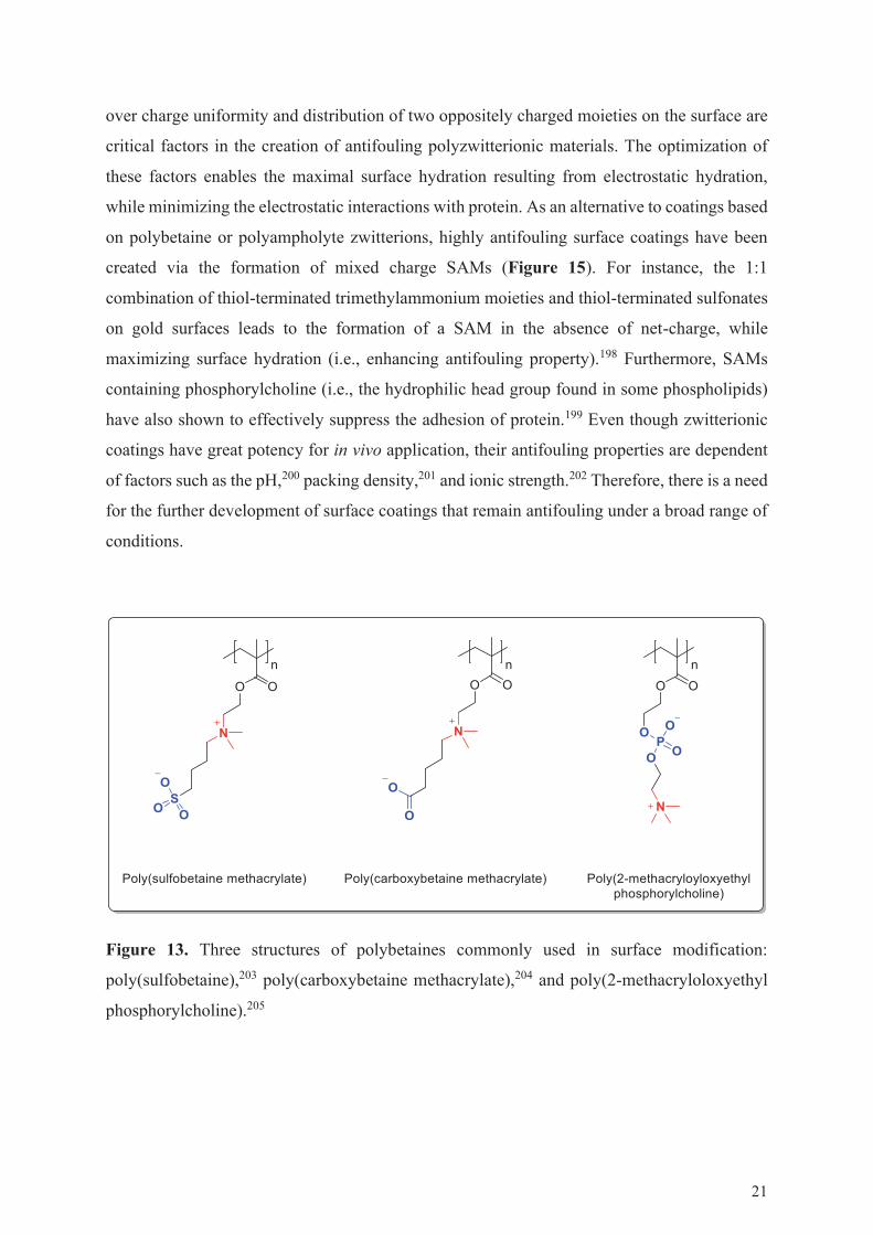
Figure 13. Three structures of polybetaines commonly used in surface modification:
poly(sulfobetaine),203 poly(carboxybetaine methacrylate),204 and poly(2-methacryloloxyethyl
phosphorylcholine).205
21
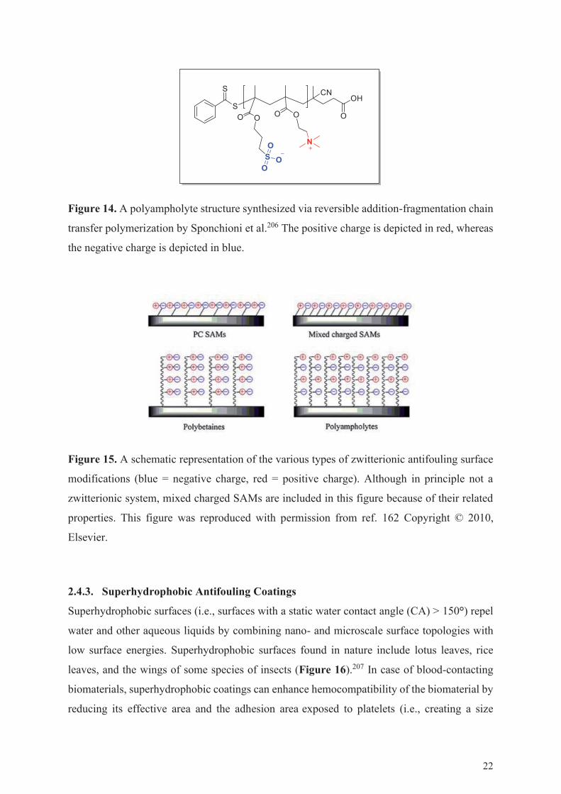
Figure 14. A polyampholyte structure synthesized via reversible addition-fragmentation chain
transfer polymerization by Sponchioni et al.206 The positive charge is depicted in red, whereas
the negative charge is depicted in blue.
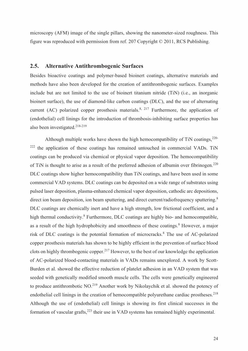
Figure 15. A schematic representation of the various types of zwitterionic antifouling surface
modifications (blue = negative charge, red = positive charge). Although in principle not a
zwitterionic system, mixed charged SAMs are included in this figure because of their related
properties. This figure was reproduced with permission from ref. 162 Copyright © 2010,
Elsevier.
2.4.3. Superhydrophobic Antifouling Coatings
Superhydrophobic surfaces (i.e., surfaces with a static water contact angle (CA) > 150°) repel
water and other aqueous liquids by combining nano- and microscale surface topologies with
low surface energies. Superhydrophobic surfaces found in nature include lotus leaves, rice
leaves, and the wings of some species of insects (Figure 16).207 In case of blood-contacting
biomaterials, superhydrophobic coatings can enhance hemocompatibility of the biomaterial by
reducing its effective area and the adhesion area exposed to platelets (i.e., creating a size
22

mismatch between platelets and topologically uniform areas).208-211 Furthermore, they can alter
the hydrodynamic properties of the biomaterial surface and reduce or alter protein adhesion,
resulting in increased blood repellency. 212-213 The protein repellence on superhydrophobic
surfaces is mediated by a surface-bound air-layer (i.e., the plastron), which is immobilized
within the roughness of the surface. The plastron presents a physical barrier that prevents the
adhesion of protein from the surrounding media. However, removal of the plastron can lead to
the exposure of a high hydrophobic surface area, to which protein or cells readily adhere.214
Although superhydrophobic surfaces can effectively reduce platelet and protein adhesion, they
tend to lose their anti-platelet properties over time mainly resulting from their low mechanical
durability.215 Furthermore, the gradual dissolution of the surface-bound air layer reduces the
stability of the plastron.216 As the fabrication of superhydrophobic coatings is often also
laborious, there is a need for easily producible superhydrophobic coatings that can effectively
prevent biomaterial-induced thrombosis, protein adhesion, and bacterial infection and have a
high plasmon stability and mechanical durability.
Figure 16. (A) A water droplet on a lotus leaf. (B) Scanning electron microscopy (SEM)-image
of a lotus leaf, showing the micrometer-sized waxy pillars on the surface. (C) An atomic force
23
microscopy (AFM) image of the single pillars, showing the nanometer-sized roughness. This
figure was reproduced with permission from ref. 207 Copyright © 2011, RCS Publishing.
2.5. Alternative Antithrombogenic SurfacesBesides bioactive coatings and polymer-based bioinert coatings, alternative materials and
methods have also been developed for the creation of antithrombogenic surfaces. Examples
include but are not limited to the use of bioinert titanium nitride (TiN) (i.e., an inorganic
bioinert surface), the use of diamond-like carbon coatings (DLC), and the use of alternating
current (AC) polarized copper prosthesis materials.8, 217 Furthermore, the application of
(endothelial) cell linings for the introduction of thrombosis-inhibiting surface properties has
also been investigated.218-219
Although multiple works have shown the high hemocompatibility of TiN coatings,220-
222 the application of these coatings has remained untouched in commercial VADs. TiN
coatings can be produced via chemical or physical vapor deposition. The hemocompatibility
of TiN is thought to arise as a result of the preferred adhesion of albumin over fibrinogen.220
DLC coatings show higher hemocompatibility than TiN coatings, and have been used in some
commercial VAD systems. DLC coatings can be deposited on a wide range of substrates using
pulsed laser deposition, plasma-enhanced chemical vapor deposition, cathodic arc depositions,
direct ion beam deposition, ion beam sputtering, and direct current/radiofrequency sputtering.8
DLC coatings are chemically inert and have a high strength, low frictional coefficient, and a
high thermal conductivity.8 Furthermore, DLC coatings are highly bio- and hemocompatible,
as a result of the high hydrophobicity and smoothness of these coatings.8 However, a major
risk of DLC coatings is the potential formation of microcracks.8 The use of AC-polarized
copper prosthesis materials has shown to be highly efficient in the prevention of surface blood
clots on highly thrombogenic copper.217 However, to the best of our knowledge the application
of AC-polarized blood-contacting materials in VADs remains unexplored. A work by Scott-
Burden et al. showed the effective reduction of platelet adhesion in an VAD system that was
seeded with genetically modified smooth muscle cells. The cells were genetically engineered
to produce antithrombotic NO.219 Another work by Nikolaychik et al. showed the potency of
endothelial cell linings in the creation of hemocompatible polyurethane cardiac prostheses.218
Although the use of (endothelial) cell linings is showing its first clinical successes in the
formation of vascular grafts,223 their use in VAD systems has remained highly experimental.
24

2.6. Mussel-inspired Surface ChemistryThe great interest in controlled modification of physicochemical surface properties has resulted
in the development of a wide range of universal (i.e., substrate-independent) polymeric
coatings. Unlike conventional coating methods, such as the functionalization of hydroxylated
surface with silanes and phosphonates,224 or the functionalization of gold surfaces with thiols
and disulfides,225 universal polymeric coatings can be applied to a broad range of materials,
independent of the chemical and physical properties of the underlaying substrate.226 In general,
surfaces can be functionalized via chemisorption or physisorption. In chemisorption, the
coating binds to the substrates via the formation of covalent bonds, thus involving a chemical
reaction between the surface and the adsorbate (e.g., the formation of thiol SAMs on gold and
the functionalization of metal oxides with phosphonic acids and alkyl silanes).224, 227
Additionally, in irradiative chemisorption surface radicals are created through irradiation to
start surface-initiated polymerization of selected monomers.228 Unlike in chemisorption,
physisorption does not involve the formation of chemical bonds between the adsorbate and the
surface. Instead, the surface-immobilization is mediated by reversible van der Waals
interactions, electrostatic interactions, hydrophobic interactions, and hydrogen bonds. The
physisorption can also be applied for the formation of multilayer systems,229 whereas
chemisorption leads to the formation of monolayers as a result of the depletion of reactive sites
on the surface. As the physisorption does not rely on the formation of chemical bonds, it is
suitable for the formation of universal coatings via various techniques, such as spin coating
and the use of LbL assemblies.229-230 However, due to the reversible binding interactions with
low binding energies, intra-layer physical or chemical crosslinking of the adsorbate material is
required for long-term stability of physisorbed coatings. Recently, various nature-inspired
universal physisorbed coatings, such as coatings based on adhesion of blood protein,231 plant
polyphenols,35, 232 and mussel-foot protein,21 have been created.
2.6.1. Mussel Adhesion
Mussels can adhere to virtually all types of organic and inorganic surfaces, including surfaces
which are classically categorized as non-fouling (e.g., polytetrafluoroethylene (PTFE)).21
Mussels adhere themselves to the substrate using their byssal threads, which are tethered to the
surface via an adhesive plaque. The proteins confined to the byssal threads and plaque include
mussel-foot protein (mfp)-1, mfp-2, mfp-3, mfp-4, mfp-5 (Figure 17A), and mfp-6, which all
contain the unusual amino acid 3,4–dihydroxyphenyl-L-alanine (i.e., DOPA) in varying
25
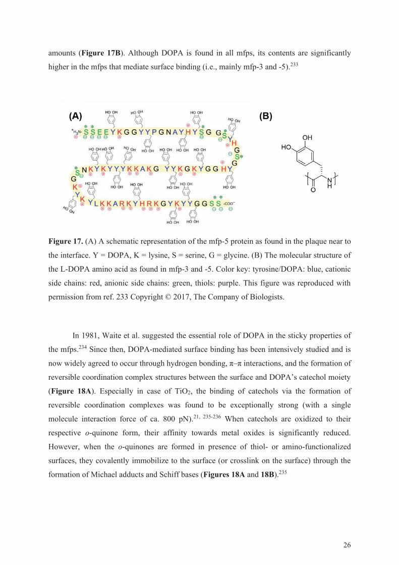
amounts (Figure 17B). Although DOPA is found in all mfps, its contents are significantly
higher in the mfps that mediate surface binding (i.e., mainly mfp-3 and -5).233
Figure 17. (A) A schematic representation of the mfp-5 protein as found in the plaque near to
the interface. Y = DOPA, K = lysine, S = serine, G = glycine. (B) The molecular structure of
the L-DOPA amino acid as found in mfp-3 and -5. Color key: tyrosine/DOPA: blue, cationic
side chains: red, anionic side chains: green, thiols: purple. This figure was reproduced with
permission from ref. 233 Copyright © 2017, The Company of Biologists.
In 1981, Waite et al. suggested the essential role of DOPA in the sticky properties of
the mfps.234 Since then, DOPA-mediated surface binding has been intensively studied and is
now widely agreed to occur through hydrogen bonding, π–π interactions, and the formation of
reversible coordination complex structures between the surface and DOPA’s catechol moiety
(Figure 18A). Especially in case of TiO2, the binding of catechols via the formation of
reversible coordination complexes was found to be exceptionally strong (with a single
molecule interaction force of ca. 800 pN).21, 235-236 When catechols are oxidized to their
respective o-quinone form, their affinity towards metal oxides is significantly reduced.
However, when the o-quinones are formed in presence of thiol- or amino-functionalized
surfaces, they covalently immobilize to the surface (or crosslink on the surface) through the
formation of Michael adducts and Schiff bases (Figures 18A and 18B).235
26

Figure 18. (A) A schematic display of the various catechol adhesion mechanisms. (i) On
surfaces that display hydrogen bond donors/acceptors, catechols can bind the formation of
hydrogen bonds, (ii) on surfaces that contain aromatic systems, catechols can bind via π–π
interactions, (iii) catechols can tether to certain metal oxide surfaces (especially TiO2) via the
formation of strong but reversible metal complexes, (iv) finally, catechols can irreversibly bind
to amine (and thiol) functionalized surfaces via the formation of Michael adducts.237 (B) A
schematic representation of the Michael-addition reactions and Schiff base formations between
amines and o-quinones.238 Furthermore, o-quinones can undergo crosslinking reactions.239 In
case of the Michael addition reaction to catechols, full understanding of the reaction
mechanism has not been achieved yet. Furthermore, when catechols are reacted with primary
amines in the presence of oxidizing agents such as NaIO4, many side products are formed, most
likely as a result of aryloxyl-phenol coupling reactions.238 The Schiff base formation was found
to only play a minor role when the reaction is performed under basic conditions (pH 11).238
Although DOPA was found to show strong and universal surface binding properties,
the sole presence of DOPA did not explain the rapid polymerization of the mfps upon mussel
adhesion. More recently, Waite et al. observed the close proximity of catechol- (i.e., DOPA)
and amine-containing amino acids (i.e., lysine and histidine) in mfp-5, leading to the hypothesis
that the coexistence of these groups was essential for rapid adhesive properties.240 This led to
the development of a variety of catechol-amine-including antifouling peptide sequences,
containing a biomimetic anchoring block rich in DOPA and lysine amino acids,170 catechol-
27

functionalized poly(ethylene amine),241 and catechol-functionalized chitosan.242 However, low
molecular weight catechol amines were not considered prior to 2007.
2.6.2. Polydopamine and Catechol Chemistry
In 2007, Messersmith et al. developed a facile dip-coating procedure for the formation of multi-
functional universal polydopamine (PDA) coatings (Figure 19).21 This breakthrough led to the
development of a wide variety of PDA-based systems, including antifouling,21
hemocompatible,243 and antibacterial surfaces.244 PDA is widely described in current scientific
literature, mainly because of its simplicity, low cost, and adaptability. The PDA coating is
created by simply submerging a substrate in an aqueous alkaline solution of dopamine for an
adjustable period of time. During the incubation, the PDA coating is spontaneously deposited.
This primary coating can then be used as a primer for the immobilization of a secondary coating
for the introduction of tailored surface properties.
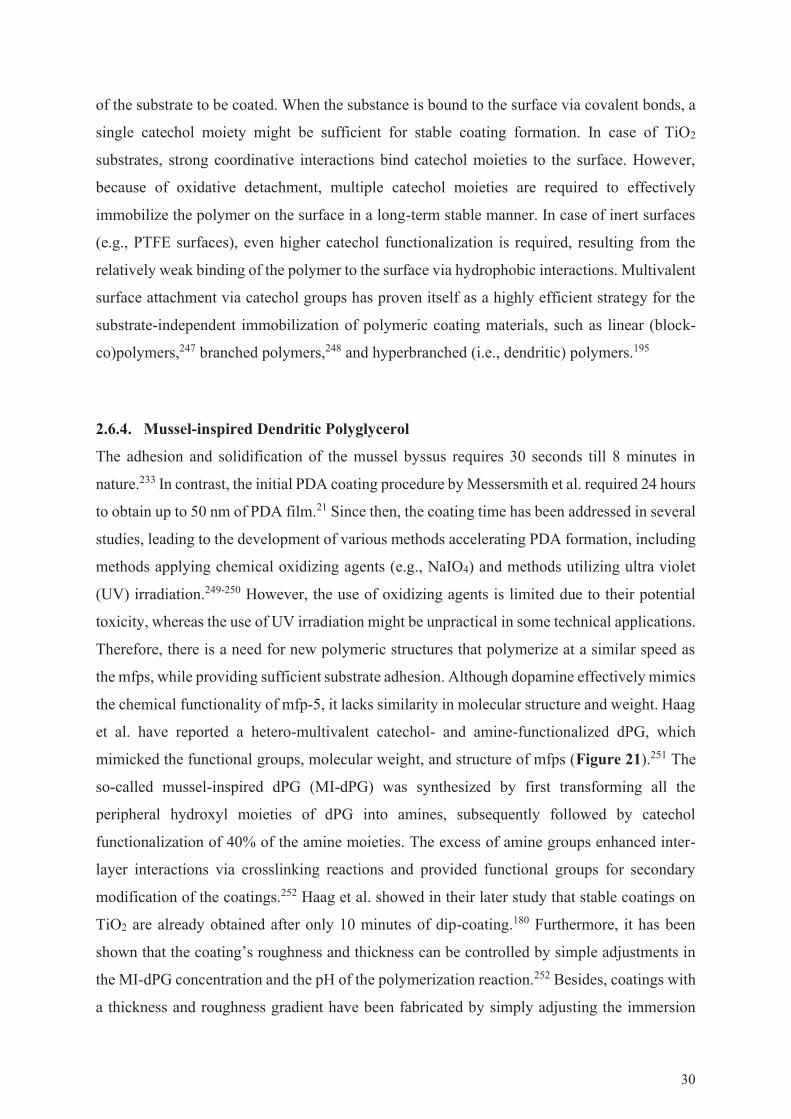
The PDA coatings form through an oxidative polymerization of dopamine, starting
from the oxidation of dopamine by dissolved oxygen at alkaline pH (Figure 20). The o-quinone
product subsequently reacts through a nucleophilic cyclization, eventually leading to the
formation of 5,6-dihydroxyindole.245 In most of the currently proposed mechanisms, 5,6-
dihydroxyindole and dopamine are considered the key building blocks of PDA. Besides,
alternative mechanisms which propose PDA as a non-covalent assembly of dopamine,
dopamine-quinone, and 5,6-dihydroxyindole have been proposed as well as a mechanism
similar to the formation of eumelanin.245 However, there is no general consensus on the exact
mechanistic details of the PDA formation, and therefore it remains the topic of current
investigations. Although PDA has proven itself as a useful tool for substrate-independent
surface modification, it suffers from slow polymerization rates and limited coating thickness
(i.e., a maximum coating thickness in nanometer range).21 Furthermore, the PDA coating is
non-transparent and has a dark-brown color, making it unsuitable for various optical
applications.
28
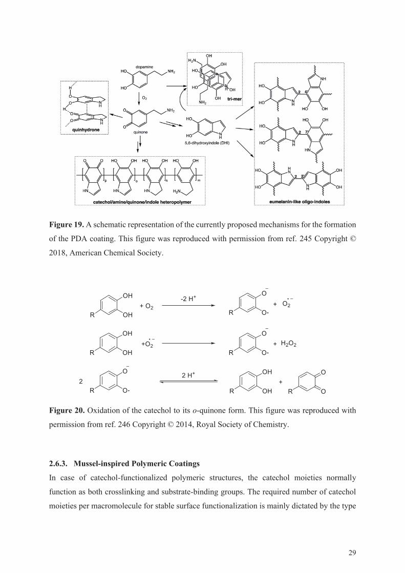
Figure 19. A schematic representation of the currently proposed mechanisms for the formation
of the PDA coating. This figure was reproduced with permission from ref. 245 Copyright ©
2018, American Chemical Society.
Figure 20. Oxidation of the catechol to its o-quinone form. This figure was reproduced with
permission from ref. 246 Copyright © 2014, Royal Society of Chemistry.
2.6.3. Mussel-inspired Polymeric Coatings
In case of catechol-functionalized polymeric structures, the catechol moieties normally
function as both crosslinking and substrate-binding groups. The required number of catechol
moieties per macromolecule for stable surface functionalization is mainly dictated by the type
29
of the substrate to be coated. When the substance is bound to the surface via covalent bonds, a
single catechol moiety might be sufficient for stable coating formation. In case of TiO2
substrates, strong coordinative interactions bind catechol moieties to the surface. However,
because of oxidative detachment, multiple catechol moieties are required to effectively
immobilize the polymer on the surface in a long-term stable manner. In case of inert surfaces
(e.g., PTFE surfaces), even higher catechol functionalization is required, resulting from the
relatively weak binding of the polymer to the surface via hydrophobic interactions. Multivalent
surface attachment via catechol groups has proven itself as a highly efficient strategy for the
substrate-independent immobilization of polymeric coating materials, such as linear (block-
co)polymers,247 branched polymers,248 and hyperbranched (i.e., dendritic) polymers.195
2.6.4. Mussel-inspired Dendritic Polyglycerol
The adhesion and solidification of the mussel byssus requires 30 seconds till 8 minutes in
nature.233 In contrast, the initial PDA coating procedure by Messersmith et al. required 24 hours
to obtain up to 50 nm of PDA film.21 Since then, the coating time has been addressed in several
studies, leading to the development of various methods accelerating PDA formation, including
methods applying chemical oxidizing agents (e.g., NaIO4) and methods utilizing ultra violet
(UV) irradiation.249-250 However, the use of oxidizing agents is limited due to their potential
toxicity, whereas the use of UV irradiation might be unpractical in some technical applications.
Therefore, there is a need for new polymeric structures that polymerize at a similar speed as
the mfps, while providing sufficient substrate adhesion. Although dopamine effectively mimics
the chemical functionality of mfp-5, it lacks similarity in molecular structure and weight. Haag
et al. have reported a hetero-multivalent catechol- and amine-functionalized dPG, which
mimicked the functional groups, molecular weight, and structure of mfps (Figure 21).251 The
so-called mussel-inspired dPG (MI-dPG) was synthesized by first transforming all the
peripheral hydroxyl moieties of dPG into amines, subsequently followed by catechol
functionalization of 40% of the amine moieties. The excess of amine groups enhanced inter-
layer interactions via crosslinking reactions and provided functional groups for secondary
modification of the coatings.252 Haag et al. showed in their later study that stable coatings on
TiO2 are already obtained after only 10 minutes of dip-coating.180 Furthermore, it has been
shown that the coating’s roughness and thickness can be controlled by simple adjustments in
the MI-dPG concentration and the pH of the polymerization reaction.252 Besides, coatings with
a thickness and roughness gradient have been fabricated by simply adjusting the immersion
30
depth of the substrate.253 In their further studies, they have introduced a nanometer roughness
and antimicrobial surface properties to the MI-dPG coating by using copper (Cu) or silver (Ag)
nanoparticles.244, 253
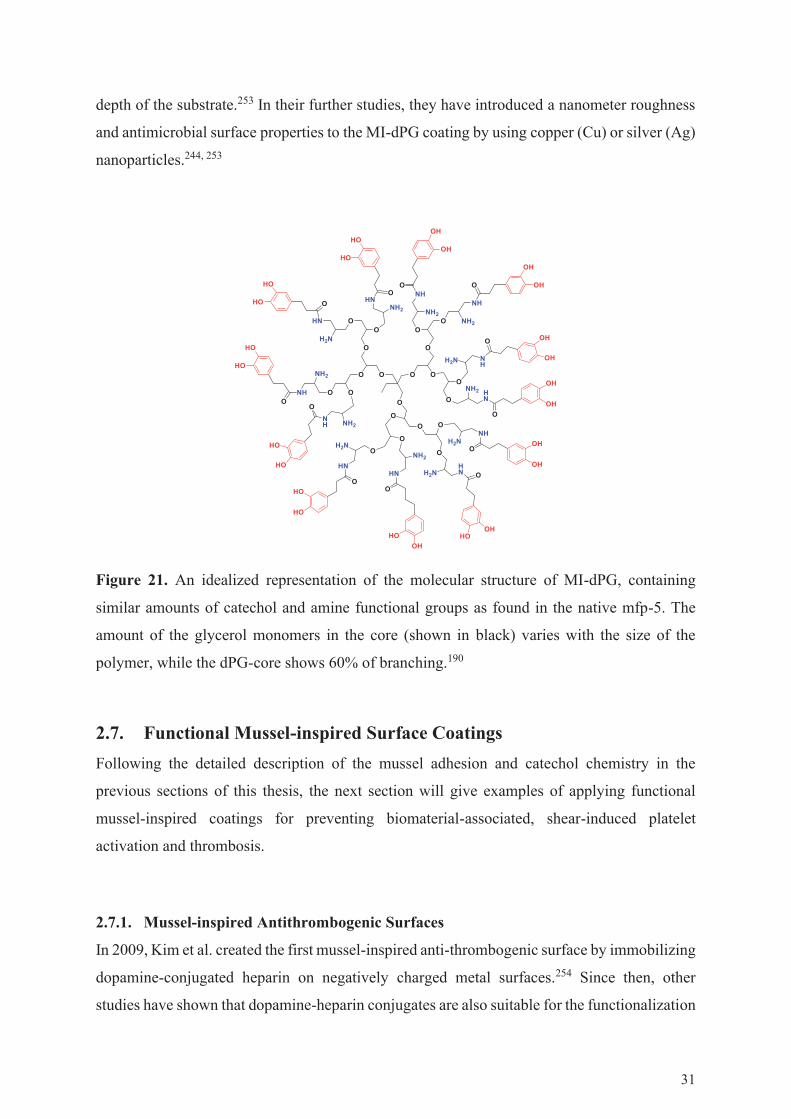
Figure 21. An idealized representation of the molecular structure of MI-dPG, containing
similar amounts of catechol and amine functional groups as found in the native mfp-5. The
amount of the glycerol monomers in the core (shown in black) varies with the size of the
polymer, while the dPG-core shows 60% of branching.190
2.7. Functional Mussel-inspired Surface CoatingsFollowing the detailed description of the mussel adhesion and catechol chemistry in the
previous sections of this thesis, the next section will give examples of applying functional
mussel-inspired coatings for preventing biomaterial-associated, shear-induced platelet
activation and thrombosis.
2.7.1. Mussel-inspired Antithrombogenic Surfaces
In 2009, Kim et al. created the first mussel-inspired anti-thrombogenic surface by immobilizing
dopamine-conjugated heparin on negatively charged metal surfaces.254 Since then, other
studies have shown that dopamine-heparin conjugates are also suitable for the functionalization
31

of polymeric surfaces, such as polyurethane (PU) an polyethersulfone (PES).144, 255 Using
dopamine-heparin conjugates circumvents the need for chemical pretreatment of the surface,
and the surface modification occurs in a single step. Therefore, employing dopamine-
conjugated heparin is an interesting alternative to other universal coating methods, which
commonly utilize complex machinery or require the substrate to have specific chemical or
physical properties.
As an alternative approach to immobilize heparin on the surface of biomaterials,
heparin has been covalently bound on a PDA coating in several blood-contacting applications,
such as heparinized stents,256 heparinized hemodialysis membranes,257 heparinized bone
implants,258 nano-anticoagulant carriers,259 and mesoporous heparin-releasing films.260 Also
catechol-functionalized, heparin-mimicking polymers have been introduced to solid
substrates.144 Other alternative approaches for the surface immobilization of heparin-
mimicking structures include the formation of LbL assemblies and the binding of heparin-
mimicking polymers to PDA films.261-263
2.7.2. Mussel-inspired Hydrophilic Antifouling Surfaces
Already in the fundamental work by Messersmith et al., a PDA film was used for immobilizing
PEG as a hydrophilic antifouling agent on the surface.21 Since then, other substrate-
independent adhesive layers, such as coatings based on MI-dPG, tannic acid, and
aminomalononitrile have been used to effectively immobilize functional polymers on the
surface.180, 264-267 Using bi-layer systems (i.e., systems consisting of an adhesive layer modified
with a functional top layer) can provide additional control over the coatings’ roughness and
thickness, which can be beneficial, for instance, in controlled stem cell culturing and in the
creation of wetting gradients for fog harvesting.252, 268-269 Additionally, the use of an adhesive
layer can introduce multiple simultaneous functionalities (e.g., the introduction of silver
nanoparticles (AgNPs) to MI-dPG in combination with an antifouling hydrophilic polymeric
top layer combines antimicrobial and antifouling surface chemistries).264
Mussel-inspired chemistry can also be used for the direct immobilization of functional
monolayers. The use of monolayer coatings might be beneficial especially in polymeric filter
membranes, as too thick coatings can obstruct the membrane’s pores, thus hampering the
membrane’s technical applicability. In a study by Wei et al., dPG was functionalized with
catechol moieties at various degrees and subsequently immobilized on a manifold of substrates
32

to introduce antifouling surface properties (Figure 22).270 In their study, a certain amount of
catechol moieties was required to immobilize dPG in a stable manner. However, when the
catechol functionalization was too high (30 %) the antifouling properties of dPG were reduced,
most likely because of the random distribution of the catechol-groups on the dPG’s periphery:
while some of the catechols were mediating surface binding, others were facing away from the
surface, thus mediating protein binding.
Figure 22. dPG-catechol monolayers with varying catechol functionalization. Wei et al.
observed that the degree of catechol functionalization influenced the stability of catechol-
functionalized dPG on the surface. Resulting from oxidation of the catechols, 1% catechol
functionalized dPG (dPG-Cat1) detached from the surface over time, resulting in the loss of
antifouling properties after 14 days of cell culturing. Higher degrees of catechol
functionalization led to more stable dPG immobilization, resulting in prolonged antifouling
properties. dPG–Cat5 = 5% catechol-functionalized dPG, dPG–Cat10 = 10% catechol
functionalized-dPG. This figure was reproduced with permission from ref. 195 Copyright ©
2014, Elsevier.
In a follow up work, Wei et al. introduced antifouling surface properties to biomedically
relevant TiO2 and polystyrene (PS) surfaces, via the use of crosslinked hierarchical polymer
multilayers.239 In case of the TiO2 substrate, Wei first immobilized dPG–Cat10 on the substrate
33

as a stable base layer. Subsequently, the base-layer was post-functionalized with dPG–Cat1,
via the use of a straightforward dip coating procedure (Figure 23A). By using this strategy, the
antifouling dPG–Cat1 was immobilized on the surface in a stable manner, which was not
possible via the direct immobilization of dPG–Cat1 on the TiO2 surface. 239 The stable
crosslinking between the dPG–Cat10 and dPG–Cat1 layers was proposed to occur through the
formation of aryl-aryl bonds between the catechol moieties of the adjacent layers. Furthermore,
it was proposed that the formation of these aryl-aryl bonds contributed to the intralayer stability
of the system (Figure 18B).239 For the functionalization of PS, the direct binding of the dPG–
Cat10 layer was found to be insufficient, resulting from the weaker binding interactions
between the catechol moieties and the substrate. Therefore, MI-dPG was first immobilized on
the PS surface, as a reactive and stable base layer. Subsequently, dPG–Cat10 and dPG–Cat1
were immobilized on the MI-dPG coating, respectively (Figure 23B). In this way, stable and
highly effective antifouling PS surfaces were obtained.239
Figure 23. A graphical representation of the hierarchical coating method developed by Wei et
al. (A) Immobilization of dPG–Cat10 and dPG–Cat1 on TiO2 substrates. (B) Immobilization
of MI-dPG, dPG–Cat10, and dPG–Cat1 on the PS surface. This figure was reproduced with
permission from ref. 239 Copyright © 2014, Wiley-VCH.
34

An alternative mussel-inspired approach was developed by Yu et al. who created a lPG
block-copolymer functionalized with a surface-binding block that carried amine, phenyl , and
catechol moieties (Figure 24).181 By applying the block-copolymer strategy, all surface
tethering groups were pointing to the surface, while the hydrophilic domain of the block-
copolymer was facing away from the substrate (i.e., effectively preventing protein adhesion).
The stability of the coating was enhanced applying additional crosslinking via monolayer
formation under slightly acidic conditions (i.e., keeping the catechol in its unoxidized form),
followed by oxidation of the catechol, leading to crosslinking reactions between the amines
and o-quinones of adjacent polymer chains.
Figure 24. A schematic representation of the block-copolymer antifouling approach as
performed by Yu et al. The block copolymer was functionalized with a surface-tethering block
containing phenyl, catechol, and amine functional groups. This figure was reproduced with
permission from ref. 181 Copyright © 2017, American Chemical Society.
35

2.7.3. Mussel-inspired Superhydrophobic/Superamphiphobic Surfaces
Superhydrophobic coatings show a high potential in the prevention of biomaterial-induced
thrombosis. Various mussel-inspired superhydrophobic coatings have been developed,
including silver nanoparticle-functionalized PDA coatings functionalized with
perfluorodecanethiols,271 superhydrophobic perfluorodecyl trichlorosilane-functionalized
PDA-coated sand,272 and n-octadecyl-functionalized PDA-coated superhydrophobic
textiles.273 Schlaich et al. created MI-dPG-based superamphiphobic surfaces (i.e., surfaces
which are both superhydrophobic and superoleophobic) via hierarchical pH-controlled
polymerization of micro- and nanostructures of MI-dPG.252 Additional use of gold and silver
nanoparticles introduced nanometer roughness to the micrometer roughed MI-dPG coating.
The hierarchical structures were subsequently functionalized using heptadecafluoroundecanoyl
chloride to introduce superamphiphobic surface properties (Figure 25).
Figure 25. A schematic representation of the work performed by Schlaich et al., who carefully
investigated the relation between surface roughness and the respective wetting properties.
Superamphiphobicity was achieved by functionalizing a micro- and nanometer roughed MI-
dPG coating with hydrophobic fluoroundecanoyl chloride (CF8). This figure was reproduced
with permission from ref. 252 Copyright © 2016, American Chemical Society.
36
As highlighted in this thesis, the use of mussel-inspired coatings shows a great potential
for the creation of surfaces with highly antifouling and hemocompatible surface properties. So
far, mussel-inspired coatings with bioactive and antifouling properties have been developed.
However, because of the various complex biological interactions between biomaterials, soluble
blood components, and the blood cells, the rational design of coatings with long-term stability
and in vivo efficiency remains challenging. Furthermore, the mechanism behind the antifouling
properties of hydrophilic surface-bound polymers is not yet fully understood. Therefore, there
is a great need for the further development of mussel-inspired antifouling and antithrombogenic
surface coatings. Additionally, the development of these coatings would benefit from the
application of flow experiments with whole blood under elevated shear conditions, as most of
the current biomaterial-related research focuses on observing anti-platelet properties under
clinically irrelevant static conditions.
3. SCIENTIFIC GOALSThe aim of the current doctoral thesis was to develop mussel-inspired PG-based coatings for
the prevention of biomaterial-related fouling. The first project of this thesis aimed at the
creation of a two-layer antifouling coating for medically relevant TiO2. The developed coating
consisted of MI-dPG as a substrate-independent adhesive layer, and oligo-amine-
functionalized linear PG (lPG–b–OA11, OA = oligo-amine) as an antifouling hydrophilic top-
layer. The lPG–b–OA11-functionalized coating was compared to a similar HO–PEG–NH2-
functionalized control coating. The first project covered the characterization and comparison
of the various coatings in respect to their formation, chemical stability, and antifouling
performance. It was hypothesized that the introduction of lPG–b–OA11 or HO–PEG–NH2 to
the MI-dPG coating would result in the formation of stable substrate-independent antifouling
coatings. Furthermore, it was expected that the multivalent immobilization of lPG–b–OA11
would contribute to its stability on the MI-dPG coating.
The second project of this thesis aimed at the application of lPG–b–OA11 and HO–
PEG–NH2-functionalized MI-dPG coatings on TiO2 in an in vitro blood platelet adhesion
model. The hemo- and biocompatibility of the various coatings was evaluated by characterizing
their cytotoxicity, complement activating properties, and platelet activating properties.
Additionally, the adhesion of blood platelets was investigated under flow conditions, utilizing
the stagnation point flow model developed by Affeld et al.111-112, 274 It was expected that the
37

introduction of lPG–b–OA11 or HO–PEG–NH2 to the MI-dPG coating would decrease the
number of adherend platelets compared to the uncoated substrate. Furthermore, the lPG–b–
OA11-functionalized system was expected to be highly biocompatible.275-276 A VAD prototype
was coated with MI-dPG under industrially feasible conditions, and a method for the
visualization of the coating was developed. It was hypothesized that the coating of complex
3D shapes (such as VADs) with MI-dPG would be feasible under flow conditions. However,
parameters such as the flow rate, polymer concentration, and buffer pH were expected to
heavily influence the coating process.
The aim of the last project of this thesis was to develop substrate-independent mussel-
inspired antifouling surface coatings, via the direct grafting of glycidol monomers from MI-
dPG-coated substrates (i.e., via the direct grafting of dPG from the MI-dPG coating).
Hydrophilic TiO2 and hydrophobic PDMS were coated with MI-dPG, and subsequently the
surface-bound amines of the MI-dPG coating were utilized to initiate the grafting of dPG from
the surface. Earlier studies have reported the direct covalent grafting of dPG from silica, steel,
and aluminum.277-279 However, these approaches all required specific physical or chemical
substrate properties, surface activation prior to the grafting process, the use of organic solvents,
or the use of the highly caustic base sodium methoxide. In contrast, the novel method developed
in the last project of this thesis was performed in the absence of organic solvents or caustic
bases, in a substrate-independent manner. It was hypothesized that the grafting procedure (i.e.,
coating thickness, surface wettability, and surface roughness) could be controlled by carefully
adjusting the reaction time and temperature.
38

4. PUBLICATIONS
4.1. Mussel-inspired Multivalent Linear Polyglycerol Coatings
Outperform Monovalent Polyethylene Glycol Coatings in Antifouling
Surface Properties
Figure 26. Graphical abstract. This figure was reproduced with permission from ref. 180
Copyright © 2019, American Chemical Society.
Michaël W. Kulka, Ievgen S. Donskyi, Nina Wurzler, Dirk Salz, Özlem Özcan, Wolfgang E.S.
Unger, Rainer Haag, ACS Appl. Bio Mater. 2019, 2, 5749.
https://doi.org/10.1021/acsabm.9b00786
Contributions: M.W.K.: Planned and coordinated the project, conducted and interpreted all
CA, AFM, SEM, and quartz crystal microbalance (with dissipation monitoring) (QCM-D)
measurements, and summarized all results, discussions, and conclusions in the form of a
scientific publication.
39

4.2. The Application of Dual-layer, Mussel-inspired, Antifouling
Polyglycerol-based Coatings in Ventricular Assist Devices
Figure 27. Graphical abstract. This figure was reproduced with permission from ref. 280
Copyright © 2020, Wiley-VCH.
Michaël W. Kulka, Sarah Smatty, Kim Silberreis, Felix Hehnen, Tim Bierewirtz, Yannic
Kerkhoff, Chuanxiong Nie, Carsten Grötzinger, Sebastian Friedrich, Lars I. Dahms, Jens
Dernedde, Ingo Grunwald, Ulrich Kertzscher, Klaus Affeld, Michael Schirner, Rainer Haag,
Wiley Adv. Mater. Interfaces 2020, Accepted.
Contributions: M.W.K.: Planned and coordinated the project, executed all synthesis and
coating experiments, and performed all SEM measurements. Interpreted all data and
summarized the results, discussions, and conclusions in the form of a scientific publication.
90
1
The Application of Dual-Layer, Mussel-Inspired, Antifouling Polyglycerol-Based Coatings
in Ventricular Assist Devices^
Michaël W. Kulka,a Sarah Smatty,b Felix Hehnen,b Tim Bierewirtz,b Kim Silberreis,a,c Chuanxiong
Nie,a Yannic Kerkhoff,a Dr. Carsten Grötzinger,d Sebastian Friedrich,e Dr. Lars Ingemar Dahms,f
Dr. Jens Dernedde,c Prof. Dr. Ingo Grunwald,g Prof. Dr. Michael Schirner,a PD Dr.-Ing. Ulrich
Kertzscher,b Prof. Dr.-Ing. Klaus Affeld,b Prof. Dr. Rainer Haag a,*
a Institute for Chemistry and Biochemistry, Freie Universität Berlin, Takustraße 3, 14195 Berlin,
Germany
b Biofluid Mechanics Lab, Charité-Universitätsmedizin Berlin, Augustenburger Platz 1, 13353
Berlin, Germany
c Institute for Laboratory Medicine, Clinical Chemistry and Pathobiochemistry, Charité -
Universitätsmedizin Berlin, Augustenburger Platz 1, 13353 Berlin, Germany
d Department of Hepatology and Gastroenterology, Charité - Universitätsmedizin Berlin,
Augustenburger Platz 1, 13353 Berlin, Germany
e Process Engineering Department, Berlin Heart GmbH, Wiesenweg 10, 12247 Berlin, Germany
f Quality Assurance and Regulatory Affairs, qtec group GmbH, Niels-Bohr-Ring 3-5, 23568
Lübeck, Germany
g Department of Industrial and Environmental Biology, Hochschule Bremen – City University of
Applied Sciences, Neustadtswall 30, 28199 Bremen, Germany
Revised Manuscript
1 2 3 4 5 6 7 8 9 1011121314151617181920212223242526272829303132333435363738394041424344454647484950515253545556575859606162636465 91

2
KEYWORDS: antifouling, polyglycerol, platelet adhesion, shear-induced thrombus formation,
stagnation-point flow model, ventricular assist device
1 2 3 4 5 6 7 8 9 1011121314151617181920212223242526272829303132333435363738394041424344454647484950515253545556575859606162636465 92

3
Abstract
Continuous-flow ventricular assist devices (VADs) have established themselves as a lifesaving
therapy option in patients with severe cardiovascular disease. Unfortunately, complications with
VADs resulting from the shear-induced formation of surface blood clots are common. In the
current work, an antifouling coating based on the combination of mussel-inspired dendritic
polyglycerol (MI-dPG) and linear polyglycerol (lPG) was tested for its cell-repelling properties,
biocompatibility, and complement activating properties. Furthermore, the adhesion and activation
of blood platelets were tested under static and flow conditions. The adhesion and proliferation of
two cell types were studied by means of LIVE/DEAD™ cell staining, and it was clearly observed
that the lPG-functionalized MI-dPG coating prevented cell adhesion. Additionally, no cell
mortality was observed on all substrates, indicating the biocompatibility of the tested coatings. All
coatings showed lower (or equal) complement-activating properties than bare titanium, which is
considered a highly biocompatible material.[1] Most importantly, the lPG-functionalized system
prevented the adhesion and activation of blood platelets under static and flow conditions. Finally,
a prototype VAD was successfully coated with MI-dPG under flow conditions. In the current
study, we proved the efficient lPG-functionalization of the MI-dPG coating to obtain cell- and
platelet-repelling surfaces. [2]
Introduction
Cardiovascular diseases (CVDs) account for 45% of all deaths, and are the main cause of death
for men in all but 12 countries of Europe.[3] The treatment of patients suffering from CVDs
includes lifestyle adaptations (such as quitting smoking and dietary changes), medication for the
1 2 3 4 5 6 7 8 9 1011121314151617181920212223242526272829303132333435363738394041424344454647484950515253545556575859606162636465 93

4
reduction of low-density lipoprotein cholesterol, cardiac rehabilitation, and surgical interventions
(e.g., coronary artery bypass grafting), percutaneous coronary intervention, and the placement of
electronic pacemakers or ventricular assist devices (VADs).[4] VADs are electro-mechanical
devices for cardiac circulation, which are used to partially or fully replace the function of a failing
heart.[5] Over the last decades, VADs have established themselves as livesaving treatment option
for patients with refractory heart failure, with a 2-year survival rate of 80%.[6] The Food and Drug
Administrations has approved the use of continuous-flow VAD systems.[7] However, the use of
these systems has its shortcommings: as a result of unspecific protein adhesion and high wall shear
rates, the formation of surface blood clots in VADs is common (Figure 1).[8] The release of these
blood clots into the bloodstream constitutes a major risk, as the clots might occlude arteries,
effectively blocking the supply of nutrition and oxygen to the downstream tissue. Additionally,
the formation of surface blood clots hinders the effectiveness of the VAD system, leading to
repeated invasive surgical interventions to clean or fully replace the VAD (i.e., in case of
intracorporeal systems). Therefore, the development of durable blood-contacting materials for the
prevention of surface blood clots is of major interest for VAD-patients.
Commonly, titanium (Ti) (covered with a natural layer of titanium dioxide (TiO2)) and its
alloys are used for the production of VADs, resulting from the excellent biocompatibility and low
costs of these materials.[9] However, the application of these materials is far from ideal with respect
to their hemocompatibility. Additionally, it seems that the potential for alternative
hemocompatible bulk biomaterials has been largely explored.[9] Consequently, scientists have
shifted their attention towards surface coatings and surface engineering for the reduction of
biomaterial-induced thrombosis. A wide variety of antithrombogenic coating materials has been
developed, and the use of coatings has proven itself as a useful strategy for the reduction of
1 2 3 4 5 6 7 8 9 1011121314151617181920212223242526272829303132333435363738394041424344454647484950515253545556575859606162636465 94

5
biomaterial-induced thrombosis in VADs. In general, VAD coatings can be divided into bioactive
coatings and inorganic/organic bioinert coatings.[9, 10, 11] Alternatively, the use of endothelial cell
linings for the reduction of biomaterial-induced thrombosis has also been investigated.[12]
Figure 1. (A) The INCOR® continuous-flow VAD system by Berlin Heart GmbH, which reaches
rotation numbers between 5,000-10,000 rotations/min (2-9 l/min), leading to shear strain rates up
to maximum 200,000 1/s. The production of this specific model of VAD was terminated at the end
of 2018. (B) Examples of thrombosis in the HeartMate II VAD system by Abbott Laboratories
(Abbott Park, Illinois, USA). The top image shows a pure fibrin clot resulting from high shear.
The bottom images shows a fibrin and blood clot (often observed at areas with lower wall shear
stress).[13] This figure was reproduced with permission from ref. 13, Copyright © 2014, Elsevier.
(C) An in silico modulation of the shear-rates within the HeartMate II VAD.[14] The red areas
1 2 3 4 5 6 7 8 9 1011121314151617181920212223242526272829303132333435363738394041424344454647484950515253545556575859606162636465 95

6
represent the areas with high shear, whereas the yellow, green, and blue areas represent the areas
with lower wall shear-stress. The blue part on the left of the image represents a flow straightener.[14]
The image clearly illustrates the wide variety of shear rates in continuous-flow VAD systems. This
figure was reproduced with permission from ref. 14, Copyright © 2016, Nature.
The immobilization of the bioactive anticoagulant heparin (i.e., an active biomolecule) has
been widely reported in scientific literature,[15] and the use of this tactic has led to a variety of
commercial systems, such as the CARMEDA BioActive Surface (W.L. Gore & Associates) and
the Hepamed Heparin Coating (Medtronic plc).[16] When inorganic bioinert coatings are discussed,
titanium nitride coatings and diamond like carbon coatings are often considered as the current
standard.[10] An alternative to bioactive antithrombogenic coatings and inorganic bioinert coatings
are polymeric antifouling surfaces,[17] which effectively prevent the initial adhesion of circulatory
proteins and cells, thus lowering the inherent thrombogenicity of the surface. Polyethylene glycol
(PEG) has classically been applied as antifouling polymer,[18] but suffers from issues considering
instability upon heating in air, and immunological recognition upon repeated exposure.[19]
Additionally, a publication by Kizhakkedathu showed that high molecular weight PEG may induce
severe red blood cell aggregation, cell toxicity, and dose dependent activation of the blood
coagulation, platelets, and complement system.[20] Therefore, there is a need for the development
of novel polymeric materials which exhibit similar or superior antifouling properties as PEGylated
surface, while showing higher thermal stability, oxidative stability, and biocompatibility under
physiological conditions. Recently, polyglycerol has emerged as an alternative to PEG with higher
oxidative stability and hemocompatibility.[20, 21]
Polymeric substances can be linked to the surface of blood contacting materials via a wide
variety of methods. Traditionally, thiol and siloxane chemistries are applied to modify noble metals
1 2 3 4 5 6 7 8 9 1011121314151617181920212223242526272829303132333435363738394041424344454647484950515253545556575859606162636465 96

7
and hydroxylated surfaces,[22] respectively. Alternatively, methods such as Langmuir-Blodgett
deposition,[23] layer-by-layer assembly,[24] irradiation-mediated grafting,[25] and electrostatic or
hydrophobic adsorption can be utilized for the effective immobilization of functional polymers on
a surface.[26] However, most of these methods require specific chemical- and/or physical properties
of the substrate or the use of complex machinery, thus limiting their application. Therefore, there
is a need for novel facile coating methods that can extend the application of polymeric coatings to
the blood-contacting materials that are hard to modify with the current methods.
An interesting alternative for the surface immobilization of polymeric substances is the use
of mussel-inspired surface chemistry. Mussels can adhere to virtually every type of substrate,
including substrates that are classically defined as non-adhesive (e.g., perfluorinated surfaces).
Mussels tether themselves to the surface via so-called byssal threads. At the end of these byssal
threads, a mixture of mussel foot proteins (mfps) is excreted in the form of an adhesive plaque
(Figure 2).[27] This adhesive plaque effectively glues the byssal thread to the substrate, hereby
fixating the mussel to the surface (even under wet conditions). A publication by Waite et al.
showed the high prevalence of lysine- and 3,4-di-hydroxy-phenylalanine (DOPA) amino acids in
the mfps that are excreted close to the plaque-substrate interface (i.e., mainly mfp-3 and mfp-5).[27]
DOPA and lysine amino acids contain amine- and catechol-functional groups, respectively.
Consequently, Waite et al. hypothesized the importance of the catechol functional group in the
substrate-independent adhesion characteristics of mfp-3 and -5.[28] Later works showed the
surface-binding of catechol functional groups via a broad range of reversible non-covalent
interactions, including the formation of hydrogen bonds, π−π stacking, and the formation of strong
but reversible complexes with metal oxides (Figure 3).[29] The tethering of catechols to metal
oxides via the formation of complex structures was found to be exceptionally strong for Ti-
1 2 3 4 5 6 7 8 9 1011121314151617181920212223242526272829303132333435363738394041424344454647484950515253545556575859606162636465 97

8
substrates (ca. 800 pN).[30] The oxidation of catechols leads to the formation of o-quinones, which
readily react with nucleophiles such as amines and/or thiols to give the respective Michael adducts
or Schiff bases. Therefore, the presence of surface-bound amines or thiols leads to the irreversible
binding of catechols via the formation of covalent bonds.[29, 30]
Figure 2. (A) Adhesion of Mytilus edulis via multiple byssal threads. The enlargement on the right
shows the adhesive plaque (the white structure) in more detail. (B) Schematic representation of the
mussel foot, which is responsible for the production and adhesion of the byssal threads to the
surface. The foot extends from the protected interior of the mussel’s shell upon the adhesion of the
mussel to the surface.[27] (C) Graphical representation of the location of the various mfps in the
adhesive plaque.[27] (D) Schematic representation of the protein sequence of adhesion-mediating
mfp-5 of Mytilus edulis (Y = DOPA, K = Lysine, S = Serine, and G = Glycine).[27] Figures (B),
1 2 3 4 5 6 7 8 9 1011121314151617181920212223242526272829303132333435363738394041424344454647484950515253545556575859606162636465 98

9
(C), and (D) were reproduced with permission from ref. 27 Copyright © 2017, The Company of
Biologists LTD.
In 2007, Messersmith et al. hypothesized that the coexistence of the amine- and catechol-
functional groups might contribute to the rapid adhesion of mussels to the substrate.[31] Therefore,
they selected dopamine as a small molecule containing both functionalities. When dopamine-
containing solutions were buffered to a slightly basic pH (as commonly found in marine
environments) the spontaneous formation of polydopamine (PDA) coatings was observed (Figure
3).[31] The PDA coatings were found to form on a wide variety of substrates, independently from
the physical- or chemical properties of the surfaces.[31] Furthermore, the covalent introduction of
amine- or thiol-terminated methoxy-(polyethylene glycol) to these PDA coatings led to the
creation of fouling-resistant surfaces.[31] Since Messersmith’s initial work, the PDA coating has
gained wide interest in the biomedical field (e.g., as a platform for bone and tissue engineering,
drug delivery, antimicrobial activity, and patterned cell adhesion).[32] However, the initial method
for the formation of PDA suffered from slow coating formation and limited coating thickness.
Additionally, the PDA coating appears dark brown/black, making it unsuitable for various optical
applications.[31]
1 2 3 4 5 6 7 8 9 1011121314151617181920212223242526272829303132333435363738394041424344454647484950515253545556575859606162636465 99

10
Figure 3. (A) Catechols can adhere to a wide variety of substrates via the formation of (I)
hydrogen-bonds, (II) π–π stacking, (III) the formation of complex-structures, and (IV) the
formation of Michael-adducts or Schiff bases.[29] (B) A summary of the proposed mechanisms for
the formation of PDA. For a detailed review on the polymerization of dopamine, the reader is
referred to the cited literature.[33] Figure (B) was adapted with permission from ref. 34 Copyright
© 2013, American Chemical Society and ref. 35 Copyright © 2012, John Wiley & Sons.
In 2014, Wei and coworkers developed mussel-inspired dendritic polyglycerol (MI-dPG)
(Figure 4), which did not only contain the functional groups that are commonly found in mfps,
but also mimicked the size and molecular weight of the mfps.[36] Subsequent polymerization of
MI-dPG under slightly alkalic oxidizing conditions led to the rapid formation of substrate-
independent coatings with controllable coating thicknesses and roughness (thickness up to 4 μm
after 4 hours of coating). Additionally, the coating appeared transparent to white, depending on
the total thickness of the coating.[36] Earlier projects by our group showed the facile post-
functionalization of the MI-dPG coating with nanoparticles and acyl chlorides, for the introduction
of tailored surface properties.[37] In the current work, TiO2 was especially of interest as it is
commonly found as the blood contacting material in the interior of VADs.[9] We rescently
demonstrated the succesfull formation of highly stable antifouling (i.e., protein and cell repelling)
coatings via the introduction of an oligo amine-functionalized block-copolymer of linear
polyglycerol (lPG–b–OA11, OA= oligo amine) to MI-dPG-coated TiO2 substrates (Figure 4).[2] It
was hypothesized that the application of such an antifouling coating could prevent the primary
adhesion of protein from the bloodstream to TiO2. Consequently, the adhesion and subsequent
activation of blood platelets could potentially be prevented. Therefore, the application of a lPG-
1 2 3 4 5 6 7 8 9 1011121314151617181920212223242526272829303132333435363738394041424344454647484950515253545556575859606162636465 100

11
functionalized MI-dPG coating in VAD systems could potentially lower the risk of shear- and
biomaterial-induced thrombosis.
The current study is a follow-up work of an earlier project by our group, which showed the
facile formation, high stability, and antifouling properties of lPG–b–OA11-functionalized MI-dPG
on TiO2 (Figure 4).[2] The aim of the current work was to investigate the applicability of this
antifouling coating with respect to reduce shear- and biomaterial-induced thrombosis on medically
relevant TiO2. The lPG–b–OA11-functionalized coating was compared to a control system, in
which the MI-dPG coating was functionalized with an amine-terminated hydroxy-polyethylene
glycol (HO–PEG–NH2). Both linear polymers were of similar molecular weight (ca. 10 kDa), but
varied in the amount of surface binding groups (i.e., multivalent surface binding via multiple amine
groups for lPG–b–OA11 versus monovalent binding via a single amine group for HO–PEG–NH2)
(Figure 4).[2] Initially, the cytotoxicity of the relevant polymers was investigated towards two cell
types. Subsequently, the proliferation, adhesion, and viability of these cells were investigated on
bare TiO2 substrate, the MI-dPG coating, and the MI-dPG coating post-functionalized with lPG–
b–OA11 or HO–PEG–NH2. Next, the complement activating properties of the various coatings
were studied. Most importantly, the adhesion and activation of blood platelets were studied on the
various substrates under static and flow conditions. Finally, the applicability of MI-dPG as a
coating material for VADs was investigated. A prototype VAD systems was coated with MI-dPG
under flow conditions, and subsequently the coating was visualized via the immobilization of a
commercially available amine-functionalized fluorophore.
1 2 3 4 5 6 7 8 9 1011121314151617181920212223242526272829303132333435363738394041424344454647484950515253545556575859606162636465 101

12
Results and Discussion
The investigated coatings consisted of MI-dPG (surface 1) post-functionalized with either lPG–b–
OA11 (surface 2) or HO–PEG–NH2 (surface 3) (Figure 4). As substrate material, glass coated with
a transparent TiO2-layer (ca. 30 nm) was utilized (see Section 1.2. of the Electronic Supplementary
Information (ESI)). The MI-dPG and lPG–b–OA11 polymers were synthesized according to
methods that were published earlier by our group.[2] In brief, MI-dPG was synthesized in a four
step synthesis, starting from dendritic polyglycerol (dPG). First, 100% of the hydroxyl functional
groups of the dPG scaffold were transformed to amines via mesylation, azidation, and subsequent
reduction of the azide groups. Next, 40% of these amines were functionalized with catechols
(Figure 4).[37a] Under basic oxidizing conditions, the MI-dPG polymer can undergo crosslinking
reactions via the formation of Michael-adducts or Schiff bases between the amine- and catechol-
functional groups of adjacent MI-dPG polymers. A previous study by our group showed that the
polymerization of MI-dPG leads to the formation of aggregates in solution, which form the MI-
dPG coating via a precipitation and aggregation mechanism.[37a] The binding of the MI-dPG
coating to the substrate occurs through the versatile binding properties of its catechol moieties
(Figures 3 and 4). Another study of our group has shown the effective formation of MI-dPG
coatings on a broad range of substrates.[36] The lPG–b–OA11 block-copolymer was synthesized in
a three-step synthesis, starting with the synthesis of a block-copolymer of ethoxyethyl glycidyl
ether (EEGE) and allyl glycidyl ether (AGE), utilizing a modified version of a method that was
earlier published by Gervais et al.[2, 38] Subsequently, the EEGE–b–AGE block-copolymer was
acetal deprotected, transforming the EEGE-block to lPG. Finally, the lPG–b–AGE polymer was
functionalized with amine-functional groups, giving the lPG–b–OA11 block-copolymer (Figure
4).[2] lPG–b–OA11 was subsequently immobilized on the MI-dPG coating utilizing a straight-
1 2 3 4 5 6 7 8 9 1011121314151617181920212223242526272829303132333435363738394041424344454647484950515253545556575859606162636465 102

13
forward dip-coating procedure under basic oxidizing conditions (i.e., lPG–b–OA11 was bound to
the MI-dPG coating via the formation of Michael-adducts and Schiff bases).[2] In addition, a PEG-
based control coating was established by incubating the MI-dPG coating with a solution of
commercially available HO–PEG–NH2 (Figure 4).[2] For a more detailed description of the
synthesis of the lPG–b–OA11 and MI-dPG polymers, the formation/stability of the various
coatings, and the antifouling characteristics of the lPG–b–OA11 functionalized MI-dPG coating,
the reader is referred to the cited literature.[2]
1 2 3 4 5 6 7 8 9 1011121314151617181920212223242526272829303132333435363738394041424344454647484950515253545556575859606162636465 103

14
Figure 4. (A) The molecular structure of MI-dPG. The shown structure is an idealized molecular
structure; the amount of the glycerol monomers in the core (in black) varies with the size of the
polymer. The dPG-core size used in this work: Mn: 12 kDa and PDI: 1.3. Furthermore, the dPG-
1 2 3 4 5 6 7 8 9 1011121314151617181920212223242526272829303132333435363738394041424344454647484950515253545556575859606162636465 104

15
core shows up to 60% of branching.[39] (B) The proposed coordination for the binding of the
catechol moieties to the TiO2 surface.[40] (C) The molecular structure of lPG–b–OA11 and HO–
PEG–NH2. (D) Catechols readily react with amine- (and/or thiol-) functionalized polymers, giving
the Schiff base and Michael addition products. Via the depicted chemistry, the MI-dPG coating
was crosslinked and post-functionalized with lPG–b–OA11 or HO–PEG–NH2 to give surfaces 2 or
3, respectively. (E) A schematic display of the functional surfaces 1, 2, and 3.
Cell Adhesion and Proliferation Tests
The proliferation and adhesion of human alveolar basal epithelial carcinoma cells (A549) and
chicken fibroblast cells (DF-1) was investigated on the various coatings, in order to assess the
biocompatibility of the substrates to a broad range of cell types. The proliferation of (for the VAD-
system more relevant) human umbilical vein endothelial cells (HUVEC) on bare TiO2 and surfaces
1, 2, and 3 was studied in detail in an earlier project of our group.[2] It is important to notice that
the coatings that were studied in this work were developed as blood-contacting materials, i.e., the
coatings would not be exposed to any sort of tissue during their application in VAD systems.
Nevertheless, it was important that the coatings showed antifouling and cell-repelling properties
while not being toxic to (any type of) cells, as the adhesion (and subsequent proliferation) of cells
from the bloodstream to the VAD’s interior could potentially lead to major complications.
Cell adhesion and proliferation was assessed by directly seeding the cells onto the bare
TiO2 substrate and surfaces 1, 2, and 3. After 24 h of culturing, the cells were stained with a
commercial LIVE/DEAD™ cell staining kit. Analysis of the stained cells was achieved utilizing
a fluorescence microscope and the Java-based, image-processing program "ImageJ" (the
quantification process is described in Figure S1 and Section 1.8. of the ESI). The adhesion and
1 2 3 4 5 6 7 8 9 1011121314151617181920212223242526272829303132333435363738394041424344454647484950515253545556575859606162636465 105

16
proliferation of the cells were also studied in the presence of high concentrations of the dissolved
lPG–b–OA11 and HO–PEG–NH2 polymers. For this, the A549 and DF-1 cells were cultured on
tissue culture polystyrene (TCPS) for 24 h. Subsequently, the cell medium was exchanged for
medium containing dissolved lPG–b–OA11 or HO–PEG–NH2 at 10 mg/ml. After another 24 h of
cell culturing, the cells were stained and the cell number, cellular morphology, and overall cell
viability were quantified. As a negative control, the cells were incubated with normal cell medium
on TCPS. The morphology of the cells was reported as a normalized shape factor that describes
the circularity of the adherent cells. Cell circularity is often used as a parameter describing the
adhesion of cells: fully circular cells (i.e., cells with a shape factor of 1) do not adhere, whereas
spread-out cells (i.e., cells with low shape factors) do adhere to the surface.
On the TCPS control, high cell numbers of both cell types were observed in comparison to
the other tested substrates (Figures 5 and 6 and Table S1 of the ESI). Furthermore, the cells were
mainly observed in their spread-out adherent state (Figures 5 and 6 and Table S1 of the ESI).
When the cells were cultured on TPCS in the presence of dissolved lPG–b–OA11, a significant
reduction in the cell number was observed for both the A549 (59% reduction in respect to TCPS)
and DF-1 cells (78% reduction in respect to TCPS) (Figures 5 and 6 and Table S1 of the ESI).
Furthermore, the DF-1 cells showed an increased circularity in respect to the bare TCPS substrate,
which indicated that the cells adhered less well to TCPS in the presence of lPG–b–OA11 (Figures
5 and 6 and Table S1 of the ESI). The A549 cells did only show a minor nonsignificant increase
in their circularity, indicating that the adhesion of the cells was only slightly reduced by the
presence of lPG–b–OA11 (Figures 5 and 6 and Table S1 of the ESI). When the cell numbers of
the A549 and DF-1 cells were quantified on TCPS in the presence of dissolved HO–PEG–NH2,
strong reductions in the cell numbers of the A549 (59% reduction in respect to TCPS) and DF-1
1 2 3 4 5 6 7 8 9 1011121314151617181920212223242526272829303132333435363738394041424344454647484950515253545556575859606162636465 106

17
cells (73% reduction in respect to TCPS) were observed. However, incubation with HO–PEG–
NH2 did not lead to significant changes in the cell circularities of both cell types, in respect to the
bare TCPS substrate (Figures 5 and 6 and Table S1 of the ESI). The observed reductions in the
cell adhesion were explained by the electrostatic binding of the positively charged amines of the
lPG–b–OA11 and HO–PEG–NH2 polymers to the negatively charged TCPS surface,[41] which led
to the formation of a surface hydration layer that functioned as a physical barrier for the prevention
of cell adhesion.[42] As a result, reduced cell numbers were observed for TCPS in the presence of
dissolved lPG–b–OA11 or HO–PEG–NH2. Furthermore, electrostatic immobilization of lPG–b–
OA11 on the TCPS substrate led to increased cell circularity for both cell types (i.e., reduced cell
adhesion), which was explained by the antifouling surface properties of the lPG–b–OA11
monolayer.[17b] The stability of the lPG–b–OA11 monolayer might have resulted from multivalent
electrostatic interactions between the amine groups of the OA-block of lPG–b–OA11 and the TCPS
surface. For the TiO2 substrate, a significant reduction in the cell number was observed in respect
to the bare TCPS substrate for both cell types (39% reduction for both cell types) (Figures 5 and
6 and Table S1 of the ESI). Additionally, the circularity of the DF-1 cells significantly increased
in respect to the TCPS substrate. A minor nonsignificant increase in the circularity was observed
for the A549 cells on TiO2 when compared to the TCPS substrate (Figures 5 and 6 and Table S1
of the ESI). For surface 1, a significant increase in the cell number of both cell types was observed
in respect to TiO2 (58% increase for the A549 cells and 71% increase for the DF-1 cells) (Figures
5 and 6 and Table S1 of the ESI). Additionally, the circularity of both cell types clearly increased
on surface 1 in respect to the bare TiO2 substrate (Figures 5 and 6 and Table S1 of the ESI).
Although higher cell numbers were observed, analysis of the cell morphology indicated that the
cells adhered less well on surface 1 than on the bare TiO2 substrate, which was explained by the
1 2 3 4 5 6 7 8 9 1011121314151617181920212223242526272829303132333435363738394041424344454647484950515253545556575859606162636465 107

18
increased hydrophilic character of surface 1 in comparison to bare TiO2. For surface 2, a significant
decrease in the cell number of both cell types was observed in respect to surface 1 (43% reduction
for the A549 cells and 53% reduction for the DF-1 cells) (Figures 5 and 6 and Table S1 of the
ESI). Furthermore, the circularity of both cell types increased on surface 2 in respect to surface 1
(Figures 5 and 6 and Table S1 of the ESI). The circularity observed for surface 2 was the highest
of all investigated substrates, indicating that surface 2 was the most effective coating for the
prevention of cell adhesion. The non-adhesion of the cells to surface 2 was in line with an earlier
work by our group, which showed the antifouling properties of surface 2.[2] The non-adherent
behavior of the cells was explained by the formation of a surface hydration layer, which formed a
physical barrier that effectively prevented the adhesion of the A549 and DF-1 cells.[42] For surface
3, a slight but nonsignificant decrease in the cell number of both cell types was observed in respect
to surface 1 (10% reduction for the A549 cells and 7% reduction for the DF-1 cells) (Figures 5
and 6 and Table S1 of the ESI). Furthermore, the circularity of both cell types clearly decreased
on surface 3 in respect to surface 1, indicating improved adhesion of the cells to the surface
(Figures 5 and 6 and Table S1 of the ESI). These results were unexpected, as the introduction of
HO–PEG–NH2 was supposed to introduce antifouling properties to the surface.[18] These findings
were explained by suboptimal grafting of the HO–PEG–NH2 polymer to surface 1, as a result from
the use of high molecular weight PEG with a single anchoring amine-group.[2, 43] As a result, the
sufficient formation of a stable surface hydration layer might have not occurred, resulting in the
adhesion of the A549 and DF-1 cells.[42] Further optimization of surface 3 (e.g., optimization of
the chain length and surface density of HO–PEG–NH2) might lead to coatings with antifouling
properties that are superior to those of surface 3. However, optimization of the PEG-based system
was beyond the scope of the current investigation.
1 2 3 4 5 6 7 8 9 1011121314151617181920212223242526272829303132333435363738394041424344454647484950515253545556575859606162636465 108

19
Next, the cell viability at the surface was investigated via LIVE/DEAD™ cell staining. The
total viability of the adherent cells was determined by dividing the amount of living cells by the
total amount of cells that were observed on the surface (Figures 5 and 6 and Table S1 of the ESI).
High cell viability (> 95%) was observed in all cases. Only for the DF-1 cells on TCPS in the
presence of dissolved lPG–b–OA11 (10 mg/ml) a slightly reduced cell viability (74.1 ± 11.3%) was
observed (Figure S4 of the ESI). This observation was explained by the presence of free amines
in the OA-block of lPG–b–OA11. Similar cytotoxic effects have also been observed for other
amine-containing polymeric structures.[44] However, it has to be noticed that lPG–b–OA11 in its
bound form (i.e., surface 2) did not reduce cell viabilities at the surface for the both cell types
(Figure S4 and Table S1 of the ESI). Besides, no reduced cell viability was observed for the A549
cells on TPCS in the presence of dissolved lPG–b–OA11 (10 mg/ml), indicating that the different
cell types were not equally sensitive to lPG–b–OA11.
1 2 3 4 5 6 7 8 9 1011121314151617181920212223242526272829303132333435363738394041424344454647484950515253545556575859606162636465 109

20
Figure 5. (A) A graphical representation of the cell numbers on the various coatings. The error
bars represent the standard deviation from the mean. The amount of cells was determined from 3
1 2 3 4 5 6 7 8 9 1011121314151617181920212223242526272829303132333435363738394041424344454647484950515253545556575859606162636465 110

21
images per coating type. (B) A graphical representation of the circularity of the cells on the various
coatings. The circularity was determined from minimal 3 images per coating type, while analyzing
minimal 20 cells per image. For the morphology analysis of the A549 and DF-1 cells on surface 2
and on TCPS incubated with lPG–b–OA11 a minimum of 5 cells per image was analyzed. The error
bars represents the standard deviation from the mean, n.s. = not significant. * p ≤ 0.05, ** p ≤ 0.01,
*** p ≤ 0.001. The p-values were calculated utilizing a 2-tailed T-test under the assumption of
equal variance.
Figure 6. LIVE/DEAD™ Staining of A549 and DF-1 cells on the various substrates. Alive cells
appear in green whereas dead cells appear in red. The scale bars represent 50 μm. Incubation of
the cells on TCPS showed the normal growth and spreading of live cells, whereas dead cells were
observed on TCPS that was incubated with medium that contained 1 wt% sodium dodecyl sulfate
1 2 3 4 5 6 7 8 9 1011121314151617181920212223242526272829303132333435363738394041424344454647484950515253545556575859606162636465 111

22
(SDS). Incubation with lPG–b–OA11 (10 mg/ml) led to reduced cell viability for the DF-1 cells,
whereas incubation with the HO–PEG–NH2 (10 mg/ml) did not affect the cell viability on the
TCPS surface. Furthermore, no reduced cell viability was observed for the A549 and DF-1 cells
on the TiO2 substrate and surfaces 1, 2, and 3.
Cytotoxicity Testing
LIVE/DEAD™ staining can only quantify toxic effects directly at the surface. Therefore, the
concentration-dependent cytotoxicity of dissolved lPG–b–OA11 and HO–PEG–NH2 was assessed
using a commercially available cell counting kit-8 (CCK-8), which is a sensitive colorimetric assay
for the quantification of viable cells. The tests were performed by culturing A549 and DF-1 cells
for 24 h on TCPS in cell medium that contained the respective polymers at various concentrations
(0.08 - 10 mg/ml). Subsequently, the cell viability in the medium was quantified (Figure S5 of the
ESI). No cytotoxicity (i.e., a cell viability of > 80%) was observed in case of the A549 cells for
lPG–b–OA11 concentrations up till 5 mg/ml (Figure S5 of the ESI). However, clearly reduced cell
viability (44.2 ± 3.2%) was observed for high lPG–b–OA11 concentrations (10 mg/ml) (Figure S5
of the ESI). In case of the DF-1 cells, no cytotoxicity was observed up till lPG–b–OA11
concentrations of 2.5 mg/ml (Figure S5 of the ESI). However, a slightly decreased cell viability
was observed for the DF-1 cells at a lPG–b–OA11 concentration of 5 mg/ml (63.0 ± 3.4% viability),
and for higher concentrations a further reduction of the cell viability was observed (41.4 ± 5.8%
viability for lPG–b–OA11 at 10 mg/ml) (Figure S5 of the ESI). Again, the reduced cell viability
was explained by the presence of free amines in the OA-block of lPG–b–OA11.[44] In contrast, HO–
PEG–NH2 did not show any cytotoxicity in both cell types up to concentrations of 10 mg/ml, which
1 2 3 4 5 6 7 8 9 1011121314151617181920212223242526272829303132333435363738394041424344454647484950515253545556575859606162636465 112

23
was explained by the biocompatible character of PEG and the low prevalence of free amines in the
polymer chains.
An earlier work of our group showed the high stability of surface 2 in both phosphate-
buffered saline (PBS) (10 mM, pH 7.4) and aqueous SDS (1 wt%) for at least one month at room
temperature.[2] Besides, only relatively low concentrations of lPG–b–OA11 are required (i.e., 1
mg/ml) for the creation of surface 2 from surface 1. Therefore, it is highly unlikely that surface 2
would release sufficient (if any) lPG–b–OA11 to elevate local concentrations of the unbound
polymer until a point of cytotoxicity. Additionally, after 24 h of cell culturing no cytotoxicity was
observed via LIVE/DEAD™ cell staining in case of surface 2 for both cell lines, furthermore
indicating the biocompatibility of the lPG–b–OA11-functionalized MI-dPG coating. The combined
cytotoxicity and cell proliferation/adhesion data showed the biocompatibility of surfaces 1, 2, and
3 and their constituents to the A549 and DF-1 cells. Furthermore, the cell repelling properties of
surface 2 were clearly displayed.
Substrate-Induced Complement Activation
Besides thrombogenicity, blood-related complement activation constitutes another important
aspect in blood compatibility.[15, 45] Therefore, the complement activation was assessed by
measuring the level of anaphylatoxin C5a in platelet rich plasma (PRP) that was exposed to the
TiO2-substrate or surfaces 1, 2, or 3, using a commercially available enzyme-linked
immunosorbent assay (ELISA). The tests were performed with full Ti-substrates (covered with a
natural TiO2-layer), as glass is known to trigger the activation of the complement system.[46]
Observations showed slightly lower C5a levels in the PRP-supernatant of surface 3 when
compared to surface 2, after 2, 3, 4, and 5 h of incubation. Nevertheless, the C5a levels observed
for the PRP on surface 2 were similar (or lower) to the levels observed for the PRP on TiO2, at t =
1 2 3 4 5 6 7 8 9 1011121314151617181920212223242526272829303132333435363738394041424344454647484950515253545556575859606162636465 113

24
3 h (1.50 ± 0.06 ng/ml for TiO2 and 1.45 ± 0.08 ng/ml for surface 2), t = 4 h (1.67 ± 0.05 ng/ml
for TiO2 and 1.40 ± 0.06 ng/ml for surface 2), and t = 5 h (1.61 ± 0.08 ng/ml for TiO2 and 1.53 ±
0.09 ng/ml for surface 2) (Table S2 and Figure S6 of the ESI). When the C5a levels at t = 5 h of
the PRP-supernatant of TiO2 and surfaces 1, 2, and 3 were compared to PRP in which complement
activation was triggered by adding zymosan from Saccharomyces cerevisiae (positive control),
lower C5a-levels were clearly observed for all substrates (Table S2 and Figure S6 of the ESI).
However, compared to non-activated PRP (negative control), all substrates showed a slight
elevation of the C5a levels (Table S2 and Figure S6 of the ESI). Still, the results showed only
minor variation between the C5a levels in the PRP-supernatant of TiO2 and surfaces 1, 2, and 3,
even after 5 h of incubation, indicating that the coatings showed similar (or even slightly better)
complement compatibility as the full Ti substrates (Table S2 and Figure S6 of the ESI).
Substrate-Induced Platelet Activation
The thrombogenicity of the biomaterials was assessed by investigating the degree of the platelet
deposition on the various substrates and by assessing the morphology of the adherent blood
platelets by means of scanning electron microscopy (SEM). As whole blood contains many other
types of blood cells, the tests were performed with PRP, which only contains blood platelets and
the soluble blood factors. Platelets change their shape from spherical to stellate appearance upon
activation (finally resulting in the formation of platelet aggregates), which can be monitored by
means of SEM.[47] Many investigations have been focused on biomaterial-induced activation of
blood platelets. However, most of these studies did not consider the time-dependent accumulation
of pro-thrombogenic protein on the surface of the biomaterial, prior to platelet adhesion and
activation. As the long-term fate of the development such a protein corona is hard to determine in
1 2 3 4 5 6 7 8 9 1011121314151617181920212223242526272829303132333435363738394041424344454647484950515253545556575859606162636465 114

25
vitro, the TiO2-substrate and surfaces 1, 2, and 3 were incubated with fibrinogen from human
plasma (Fib) as a pro-thrombogenic agent, prior to the platelet adhesion experiments. Fib is
considered the main protein promoting the adhesion of platelets to biomaterials under low shear
conditions.[48] In this way, the long-term aggregation of pro-thrombogenic protein on the various
substrates was simulated. From now on, the Fib-incubated substrates will be referred to as "surface
X (Fib)", whereas the non-Fib-incubated substrates will be denoted as "surface X" (with X = the
TiO2 substrate or surface 1, 2, or 3). Analysis of TiO2 (Fib) and surface 1 (Fib) clearly showed the
formation of large aggregates of activated platelets after 3 h incubation with PRP at 37 oC (Figure
7). In contrast, on surface 2 (Fib) the platelets were mainly found in their inactivated spherical
shape, which was explained by the reduced degradation of Fib as a result of the high presence of
–OH moieties at the surface.[48] Furthermore, the overall number of platelets appeared to be lower
on surface 2 (Fib) than on the other surfaces. For surface 3 (Fib), the results varied, and the
platelets were found in both activated and inactivated form. Nevertheless, fewer platelets seemed
to appear on surface 3 (Fib) than on the TiO2-substrate and surface 1 (Fib). The overall number of
platelets on the surface is often used to indicate the thrombogenicity of the surface.[49] However,
in this work the platelets merged in their final stage of activation. Therefore, exact platelet
quantification was challenging (and therefore considered inaccurate) when performed by SEM.
1 2 3 4 5 6 7 8 9 1011121314151617181920212223242526272829303132333435363738394041424344454647484950515253545556575859606162636465 115

26
Figure 7. (A) SEM images of the TiO2-substrate (Fib), and surfaces 1 (Fib), 2 (Fib), and 3 (Fib)
after incubation with PRP, at an enlargement of 1,500x. (B) SEM images of the same surfaces at
an enlargement of 3,500x. Strong activation and platelet spreading was observed on the TiO2-
substrate (Fib) and surface 1 (Fib). Surface 2 (Fib) showed almost no adhesion of platelets.
Additionally, the settled platelets were mainly found in their inactive, spherical state. On surface
3 (Fib), fewer platelets were observed than on the TiO2-substrate (Fib) and surface 1 (Fib).
Nevertheless, the number of platelets seemed higher for surface 3 (Fib) than for surface 2 (Fib).
1 2 3 4 5 6 7 8 9 1011121314151617181920212223242526272829303132333435363738394041424344454647484950515253545556575859606162636465 116

27
Furthermore, many of the platelets observed on surface 3 (Fib) appeared in their activated
morphology.
Platelet Adhesion in the Stagnation-Point Flow Model
In order to perform in vitro quantitative monitoring of platelet adhesion under variable wall shear
conditions, Affeld and coworkers developed the stagnation-point flow model (Figure S2 of the
ESI).[8b, 50] The stagnation-point flow model was developed to mimic the blood flow at the
bifurcations of larger blood vessels, and therefore it assesses the adhesion of platelets under
clinically relevant wall shear rates. The stagnation-point flow model enables visualization of
platelet adhesion at wall shear stresses from 0-180 1/s in a single measurement, by using a custom-
made flow chamber, a fluorescence-inverted microscope, and blood containing fluorescently
labeled platelets (Figure 8). To investigate platelet adhesion to the TiO2-substrate and surfaces 1,
2, and 3 in the stagnation-point flow model, glass cover slips were coated with a transparent TiO2
layer by means of PVD (see Section 1.2. of the ESI). Subsequently, these cover slips were
functionalized to give surfaces 1, 2, and 3, respectively. Collagen-coated glass substrates were
used as positive control to confirm the clotting ability of the blood. Besides, coverslips that were
spin-coated with polyurethane (PU) or polydimethylsiloxane (PDMS) were tested as medically
relevant reference materials.[51] Substrates within one sequence, (i.e., TiO2, PU, PDMS, collagen,
and surfaces 1, 2, and 3), were always performed with blood originating from the same donor,
ensuring that the observations resulted from the different coating types, rather than from donor-
related blood variations. In total, 9 sequences were performed, i.e., every substrate was tested with
blood from 9 different donors. Furthermore, the order in which the substrates were measured was
varied in such a manner, that it was ensured that the observations resulted from the coating’s
1 2 3 4 5 6 7 8 9 1011121314151617181920212223242526272829303132333435363738394041424344454647484950515253545556575859606162636465 117
28
surface properties, rather than from time-dependent alterations of the blood. Although large
variations are common in platelet adhesion experiments,[8b] a clear reduction in platelet adhesion
was observed from collagen (the adhesion to collagen was set to 100%) > PDMS (93.4 ± 11.0%
adhesion respective to collagen) > PU (80.9 ± 17.2% adhesion respective to collagen) > surface 3
(71.3 ± 22.7% adhesion respective to collagen) > TiO2 (60.0 ± 27.0% adhesion respective to
collagen) > surface 1 (34.7 ± 16.7% adhesion respective to collagen) > surface 2 (13.6 ± 8.2%
adhesion respective to collagen) (Figure 8 and Table S3 of the ESI). The highest surface coverage
was observed for collagen, which was explained by the high affinity of the platelets’ collagen
receptors to the collagen substrate.[52] High platelet adsorption was also observed for the PDMS
spin-coated substrate, which was explained by the hydrophobic character of this surface.[48, 53]
Interestingly, TiO2-substrate seemed to perform well at first sight. However, single-dispersed
platelets were always observed at t = 240 sec (Figure 8). When compared to the TiO2 substrate,
higher surface coverage was observed for the PU substrate, which was explained by the more
hydrophobic character of PU when compared to the TiO2 substrate.[48, 53] Surface 1 showed a
significant reduction of platelet adhesion in comparison to TiO2, which was in line with the
increased hydrophilic character of the surface.[48, 53] Surface 2 clearly showed the best platelet-
repelling properties of all tested substrates, which was explained by the formation of a tightly
bound surface water layer that prevented the adhesion of pro-coagulant protein (i.e., Fib and/or
von Willebrand factor).[42] Surprisingly, surface 3 showed a relatively high surface coverage with
platelets, which potentially resulted from a suboptimal PEG grafting density as a consequence of
monovalent grafting of the PEG chains and the use of high molecular weight PEG (Figure 8).
However, it is expected that optimization of the PEG-chain density on the MI-dPG coating will
lead to surfaces that show better antifouling properties than surface 3.[2, 20, 43]
1 2 3 4 5 6 7 8 9 1011121314151617181920212223242526272829303132333435363738394041424344454647484950515253545556575859606162636465 118
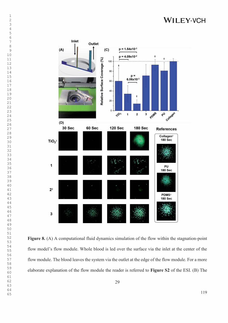
29
Figure 8. (A) A computational fluid dynamics simulation of the flow within the stagnation-point
flow model’s flow module. Whole blood is led over the surface via the inlet at the center of the
flow module. The blood leaves the system via the outlet at the edge of the flow module. For a more
elaborate explanation of the flow module the reader is referred to Figure S2 of the ESI. (B) The
1 2 3 4 5 6 7 8 9 1011121314151617181920212223242526272829303132333435363738394041424344454647484950515253545556575859606162636465 119

30
holder for the flow module on top of the fluorescence microscope. The flow module is placed in
the circle-structure. (C) Graphical representation of the relative platelet adhesion in the stagnation-
point flow model at t = 180 s. All values shown are relative to the adhesion observed for the
collagen positive control (i.e., the adhesion to collagen was set to 100%). The results showed that
surface 2 clearly suppressed the adhesion of blood platelets. The error bars represent the standard
deviation from the mean. All measurements were performed with n = 9, ǂn = 8. The p-values were
calculated using a two-tailed T-test while assuming unequal variance. (D) The fluorescence images
obtained from the stagnation-point flow model for the TiO2-substrate and surfaces 1, 2, and 3 at
various time points. Additionally, PU and PDMS were also included in the measurements.
Coating Applicability in VADs
To study the applicability of surface 1 on complex 3-dimensional substrates such as VADs,
fluorescence studies of surface 1 post-functionalized with a commercially available amine-
functionalized fluorophore (tetramethylrhodamine (TAMRA)-amine (5-isomer)) were performed
on a prototype VAD that was provided by Berlin Heart GmbH (Berlin, Germany) (Figure 9).
Optimization of the TAMRA-amine post-functionalization was performed prior to the coating
procedure (Figure S3 of the ESI), in order to prevent false positives in the absence of the MI-dPG
coating.
1 2 3 4 5 6 7 8 9 1011121314151617181920212223242526272829303132333435363738394041424344454647484950515253545556575859606162636465 120

31
Figure 9. Schematic representation of the functionalization of surface 1 with TAMRA-amine.
Fluorescence studies showed that the VAD prototype was successfully coated under low
rotational speed (90 rotations/min) (Figure 10). However, the fluorescence seemed more apparent
at the edges of the rotor blade. These results were explained by the rotation of the rotor blade
during the coating process, which might have led to a locally enhanced transport of MI-dPG and
TAMRA-amine to the surface. To obtain a more homogenous distribution of the coating, the
functionalization of the rotor blade was performed again under static conditions (i.e., dip coating).
However, the fluorescence measurements showed similar results after introduction of the
fluorophore to the MI-dPG coating. This observation was explained by the scattering of the
incident light by the rounded shapes of the rotor blade. The results illustrated the limitations of
fluorescence spectroscopy as a method for the control of the coating’s quality. However, the
combined results showed the suitability of surface 1 in the on-line coating of VADs, i.e., the
complete blood-contacting surface of a VAD was coated with MI-dPG under flow conditions,
despite the aggregation and precipitation mechanism that underlies the formation of the MI-dPG
coating.[37a] Based on an earlier study by our group, the further functionalization of surface 1 with
1 2 3 4 5 6 7 8 9 1011121314151617181920212223242526272829303132333435363738394041424344454647484950515253545556575859606162636465 121

32
lPG–b–OA11 will lead to the formation of a highly stable protein- and cell-repelling surface within
the VAD system.[2] Furthermore, the current study clearly showed the in vitro effectiveness of
surface 2 in the reduction of platelet activation and adhesion under static and flow conditions.
Therefore, surface 2 shows the potential to reduce biomaterial- and shear-induced thrombosis in
VAD systems and other blood-contacting materials.
Figure 10. The VAD was MI-dPG coated under flow conditions and subsequently functionalized
with TAMRA-amine at 10 μg/ml. (A) The picture shows the top plate of the coated VAD
prototype. The illuminated channel represents the blood outlet of the VAD. (B) The rotor blade of
the dynamically coated VAD, showing local variations in the fluorescence intensity. (C) The body
of the VAD. The top plate shown in (A) is placed on top of this body to close the VAD, whereas
1 2 3 4 5 6 7 8 9 1011121314151617181920212223242526272829303132333435363738394041424344454647484950515253545556575859606162636465 122

33
the rotor blade shown in (B) is placed in the illuminated channel shown in (C). It was clearly
observed that the blood outlet was successfully coated (right top of (C)). The VAD chamber
showed bright fluorescence, which resulted from the TAMRA-amine functionalization of the MI-
dPG coating in the VAD. (D) The dip-coated rotor blade after TAMRA-amine functionalization.
The fluorescence appeared almost equal to the fluorescence that was observed for the rotor blade
that was coated with MI-dPG under flow conditions.
Conclusions
In the current work, the cell and platelet repelling properties of MI-dPG and MI-dPG post-
functionalized with lPG–b–OA11 or HO–PEG–NH2 were investigated, in order to prove the
applicability of the various coatings in the prevention of biomaterial- and shear-induced
thrombosis in continuous-flow ventricular assist devices. When the adhesion and proliferation of
adenocarcinomic human alveolar basal epithelial cells and chicken fibroblast cells were studied on
the various substrates by fluorescent staining of the live and dead cells, it was clearly observed
that the MI-dPG coating post-functionalized with lPG–b–OA11 outperformed all other systems
considering the rejection of cellular adhesion. These findings were in line with an earlier work by
our group, which showed the protein and cell-repelling properties of the lPG–b–OA11-
functionalized MI-dPG coating. High viabilities (> 95%) were observed for all coating types.
Subsequently, the cytotoxicity of the dissolved lPG–b–OA11 and HO–PEG–NH2 polymers towards
adenocarcinomic human alveolar basal epithelial cells and chicken fibroblast cells was
investigated in cell culture based experiments, in order to simulate leaching-induced cytotoxicity
of these (water soluble) polymers. For the lPG–b–OA11 polymer no cytotoxicity was observed
until 5 mg/ml and 2.5 mg/ml for the A549 and the DF-1 cells, respectively. For HO–PEG–NH2,
no cytotoxicity was observed until 10 mg/ml for both cell lines. It is important to notice that
1 2 3 4 5 6 7 8 9 1011121314151617181920212223242526272829303132333435363738394041424344454647484950515253545556575859606162636465 123
34
leaching of HO–PEG–NH2 and lPG–b–OA11 was not expected, based on the stability data
presented in an earlier work of our group.[2] Adenocarcinomic human alveolar basal epithelial
cells and chicken fibroblast cells were used in the current study, in order to show the
biocompatibility of the tested coatings and their respective constituents to a broad range of cell
types. Furthermore, the proliferation and adhesion of medically more relevant human umbilical
vein endothelial cells on the various coatings were already investigated in an earlier study by our
group.[2] It is important to notice, that in their aimed application, the coatings would not get into
contact with any type of tissue (i.e., the coatings were developed as blood-contacting materials for
the interior of VADs). Nevertheless, it was important that the coatings would reject cellular
adhesion without being toxic to cells, as the adhesion and subsequent proliferation of cells from
the bloodstream to the blood-contacting surface of the VAD could potentially lead to major
complications.
When the substrate-induced activation of the complement system was analyzed by
measuring the C5a levels in platelet rich plasma that had been incubated with the various coatings,
no clear increase of C5a was observed in comparison to the bare TiO2-substrate. Platelet activation
tests at near static conditions showed a strong activation of platelets on the fibrinogen-incubated
TiO2 and MI-dPG surfaces. Less platelet activation was observed on (fibrinogen-incubated) MI-
dPG post-functionalized with monovalent PEG, and almost no activation was seen on (fibrinogen-
incubated) MI-dPG that was post-functionalized lPG–b–OA11. When platelet adhesion from whole
blood was investigated in the stagnation-point flow model under defined low shear-rates (0-180
1/s), high platelet adhesion was observed for the collagen-, PDMS-, PU-, and the TiO2 substrates.
The introduction of the MI-dPG coating significantly reduced the number of adherent platelets.
The lowest number of platelets was clearly observed on MI-dPG post-functionalized with lPG–b–
1 2 3 4 5 6 7 8 9 1011121314151617181920212223242526272829303132333435363738394041424344454647484950515253545556575859606162636465 124

35
OA11. The low adhesion to the lPG–b–OA11 post-functionalized MI-dPG coating was explained
by the formation of a surface hydration layer that effectively formed a barrier layer that prevented
platelet adhesion.[15] Strong adhesion of blood platelets was observed for MI-dPG post-
functionalized with HO–PEG–NH2, which most likely resulted from the use of a high molecular
weight PEG and a suboptimal monovalent grafting of the linear polymer.[2, 20, 43] Finally, a VAD
was coated with MI-dPG using a circulation system that allowed for the adhesion of MI-dPG while
the pump was running at lower rotational speed. Subsequent visualization of the coating was
achieved by the post-functionalization of the MI-dPG coating with a commercially available
fluorophore. The fluorescence data showed the successful coating of the whole interior of the
VAD.
To summarize: the combined results clearly indicated that the MI-dPG coating post-
functionalized with lPG–b–OA11 showed better antifouling surface properties than TiO2, MI-dPG,
and the MI-dPG coating that was post-functionalized with HO–PEG–NH2. Furthermore, no
cytotoxicity and obvious complement activation were observed for any of the coatings that were
topic of the current study. The lPG–b–OA11 functionalized MI-dPG coating successfully prevented
the activation of blood platelets under static conditions, and furthermore prevented the adhesion
of activated blood platelets under medically relevant flow conditions. Additionally, MI-dPG was
used to successfully coat a VAD under flow conditions. The combined results identify the lPG–b–
OA11 functionalized MI-dPG coating as a promising material for the effective reduction of surface
blood clots in 3-dimensional, blood-contacting implant devices such as continuous-flow VADs.
1 2 3 4 5 6 7 8 9 1011121314151617181920212223242526272829303132333435363738394041424344454647484950515253545556575859606162636465 125

36
Experimental Section
All materials and methods can be found in the ESI.
Acknowledgements
We would kindly like to thank Dr. D. Salz (Fraunhofer IFAM, Bremen) for providing us with the
TiO2-coated glass substrates. Furthermore, we would like to thank the physicians Dr. N. Al Besher
and Dr. M. Buhlaiga (Institute for Transfusion medicine, Charité-Universitätsmedizin Berlin,
Berlin), for their support considering the blood samples. Besides, we would like to thank Dr. C.
Schlaich (Freie Universität Berlin, Berlin) for synthesizing the used MI-dPG. Additionally, we
would like to thank S. Zürner, Dr. L. Kaufmann, and Dr. V. Kunz (Berlin Heart GmbH, Berlin)
for their technical support considering the VAD prototype. We would also like to thank Dr. P.
Winchester and Dr. R. Randriantsilefisoa for proofreading the manuscript. Finally, we would like
to acknowledge the assistance of the BioSupraMol core facility (located at the Freie Universität
Berlin and supported by the Deutsche Forschungsgemeinschaft) in the characterization of the used
polymeric materials.
Received: ((will be filled in by the editorial staff))
Revised: ((will be filled in by the editorial staff))
Published online: ((will be filled in by the editorial staff))
1 2 3 4 5 6 7 8 9 1011121314151617181920212223242526272829303132333435363738394041424344454647484950515253545556575859606162636465 126
37
References
[1] M. Saini, Y. Singh, P. Arora, V. Arora, K. Jain, World Journal of Clinical Cases: WJCC
2015, 3, 52.
[2] M. W. Kulka, I. S. Donskyi, N. Wurzler, D. Salz, Ö. Ozcan, W. E. S. Unger, R. Haag, ACS
Applied Bio Materials 2019, 2, 5749.
[3] E. Wilkins, L. Wilson, K. Wickramasinghe, P. Bhatnagar, J. Leal, R. Luengo-Fernandez,
R. Burns, M. Rayner, N. Townsend, European Cardiovascular Disease Statistics 2017
2017.
[4] J. A. Ambrose, R. S. Barua, Journal of the American College of Cardiology 2004, 43, 1731;
b) J. Kochar, J. M. Gaziano, L. Djoussé, Aging and Disease 2011, 2, 149; c) B. A. Ference,
H. N. Ginsberg, I. Graham, K. K. Ray, C. J. Packard, E. Bruckert, R. A. Hegele, R. M.
Krauss, F. J. Raal, H. Schunkert, G. F. Watts, J. Borén, S. Fazio, J. D. Horton, L. Masana,
S. J. Nicholls, B. G. Nordestgaard, B. van de Sluis, M.-R. Taskinen, L. Tokgözoğlu, U.
Landmesser, U. Laufs, O. Wiklund, J. K. Stock, M. J. Chapman, A. L. Catapano, European
Heart Journal 2017, 38, 2459; d) L. Anderson, N. Oldridge, D. R. Thompson, A.-D.
Zwisler, K. Rees, N. Martin, R. S. Taylor, Journal of the American College of Cardiology
2016, 67, 1; e) P. W. Serruys, M.-C. Morice, A. P. Kappetein, A. Colombo, D. R. Holmes,
M. J. Mack, E. Ståhle, T. E. Feldman, M. van den Brand, E. J. Bass, N. Van Dyck, K.
Leadley, K. D. Dawkins, F. W. Mohr, New England Journal of Medicine 2009, 360, 961;
f) S. K. Mulpuru, M. Madhavan, C. J. McLeod, Y.-M. Cha, P. A. Friedman, Journal of the
American College of Cardiology 2017, 69, 189.
[5] M. M. Givertz, Circulation 2011, 124, e305.
1 2 3 4 5 6 7 8 9 1011121314151617181920212223242526272829303132333435363738394041424344454647484950515253545556575859606162636465 127
38
[6] A. R. de Biasi, K. B. Manning, A. Salemi, The Journal of Thoracic and Cardiovascular
Surgery 2015, 149, 667.
[7] K. Kirklin, D. C. Naftel, F. D. Pagani, R. L. Kormos, L. W. Stevenson, E. D. Blume, M.
A. Miller, J. T. Baldwin, J. B. Young, The Journal of Heart and Lung Transplantation
2014, 33, 555.
[8] a) M. Weber, H. Steinle, S. Golombek, L. Hann, C. Schlensak, H. P. Wendel, M. Avci-
Adali, Frontiers in Bioengineering and Biotechnology 2018, 6, 1; b) K. Affeld, J. Schaller,
T. Wölken, T. Krabatsch, U. Kertzscher, Biointerphases 2016, 11, 029804.
[9] a) T. G. Kim, H. Lee, Y. Jang, T. G. Park, Biomacromolecules 2009, 10, 1532; b) S.
Alibeik, S. Zhu, J. W. Yau, J. I. Weitz, J. L. Brash, Acta Biomaterialia 2011, 7, 4177; c) J.
Lahann, D. Klee, W. Pluester, H. Hoecker, Biomaterials 2001, 22, 817.
[10] D.-C. Sin, H.-L. Kei, X. Miao, Expert Review of Medical Devices 2009, 6, 51.
[11] K. Yamazaki, S. Kihara, T. Akimoto, O. Tagusari, A. Kawai, M. Umezu, J. Tomioka, R.
L. Kormos, B. P. Griffith, H. Kurosawa, The Japanese Journal of Thoracic and
Cardiovascular Surgery 2002, 50, 461.
[12] a) V. V. Nikolaychik, D. M. Wankowski, M. M. Samet, P. I. Lelkes, American Society for
Artificial Internal Organs Journal 1996, 42, 487; b) T. Scott-Burden, C. L. Tock, J. P.
Bosely, F. J. Clubb, S. M. Parnis, J. J. Schwarz, D. A. Engler, O. H. Frazier, S. W.
Casscells, Circulation 1998, 10, 11339.
[13] N. Uriel, J. Han, K. A. Morrison, N. Nahumi, M. Yuzefpolskaya, A. R. Garan, J. Duong,
P. C. Colombo, H. Takayama, S. Thomas, Y. Naka, U. P. Jorde, Journal of Heart and Lung
Transplantation 2014, 33, 51.
1 2 3 4 5 6 7 8 9 1011121314151617181920212223242526272829303132333435363738394041424344454647484950515253545556575859606162636465 128

39
[14] W. Wu, F. Yang, J. Wu, N. Aubry, M. Massoudi, J. F. Antaki, Scientific Reports 2016, 6.
[15] C. Cheng, S. Sun, C. Zhao, Journal of Materials Chemistry B 2014, 2, 7649.
[16] R. Biran, D. Pond, Advanced Drug Delivery Reviews 2017, 112, 12.
[17] a) M. Amiji, K. Park, Journal of Biomaterials Science, Polymer Edition 1993, 4, 217; b)
M. Weinhart, T. Becherer, N. Schnurbusch, K. Schwibbert, H.-J Kunte, R. Haag, Advanced
Engineering Materials 2011, 13, B501; c) M. Wyszogrodzka, R. Haag,
Biomacromolecules 2009, 10, 1043; d) T. Becher, Q. Wei, P.-L. M. Noeske, I. Grunwald,
R. Haag, Advanced Materials 2014, 26, 2688; e) L. Liu, Q. Liu, A. Singh, Proteins at
Interfaces III State of the Art, 2012, 1120, 661; f) T. Mohan, R. Kargl, K. E. Tradt, M. R.
Kulterer, M. Braćić, S. Hribernik, K. Stana-Kleinschek, V. Ribitsch, Carbohydrate
Polymers 2015, 116, 149; g) X. Jin, J. Yuan, J. Shen, Colloids and Surfaces 2016, 145,
275; h) S. Jiang, Z. Cao, Advanced Materials 2010, 22, 920; i) A. K. Epstein, T.-S. Wong,
R. A. Belisle, E. M. Boggs, J. Aizenberg, Proceedings of the National Academy of Sciences
of the United States of America 2012, 109, 13182.
[18] a) W. R. Gombotz, W. Guanghui, T. A. Horbett, A. S. Hoffman, Journal of Biomedical
Materials Research 1991, 25, 1547; b) L. D. Unsworth, H. Sheardown, J. L. Brash,
Langmuir 2005, 21, 1036; c) K. Prime, G. Whitesides, Science 1991, 252, 1164; d) L. J.
Ho, K. Jindrich, A. J. D., Journal of Biomedical Materials Research 1989, 23, 351; e) K.
L. Prime, G. M. Whitesides, Journal of the American Chemical Society 1993, 115, 10714.
[19] a) S. Han, C. Kim, D. Kwon, Polymer 1997, 38, 317; b) A. Judge, K. McClintock, J. R.
Phelps, I. MacLachlan, Molecular Therapy 2006, 13, 328.
[20] M. Imran ul-haq, B.F. Lai, J.N. Kizhakkedathu, Biomaterials 2012, 33, 9135.
1 2 3 4 5 6 7 8 9 1011121314151617181920212223242526272829303132333435363738394041424344454647484950515253545556575859606162636465 129
40
[21] C. Siegers, M. Biesalski, R. Haag, Chemistry 2004, 10, 2831.
[22] a) C. D. Bain, E. B. Troughton, Y. T. Tao, J. Evall, G. M. Whitesides, R. G. Nuzzo, Journal
of the American Chemical Society 1989, 111, 321; b) A. Y. Fadeev, Y. V. Kazakevich,
Langmuir 2002, 18, 2665.
[23] D. Kubies, L. Machová, E. Brynda, J. Lukáš, F. Rypáček, Journal of Materials Science:
Materials in Medicine 2003, 14, 143.
[24] C. Boura, P. Menu, E. Payan, C. Picart, J. C. Voegel, S. Muller, J. F. Stoltz, Biomaterials
2003, 24, 3521.
[25] P. Petrov, G. Georgiev D. Momekova G. Momekov, C. B. Tsvetanov, Polymer 2010, 51,
2465.
[26] a) P. Bertrand, A. Jonas, A. Laschewsky, R. Legras, Macomolecular Rapid
Communications 2000, 21, 319; b) C. Freij-Larsson, T. Nylander, P. Jannasch, B. Wesslén,
1996, Biomaterials, 17, 2199.
[27] J. H. Waite, The Journal of Experimental Biology 2017, 220, 517.
[28] J. H. Waite, M. L. Tanzer, Science 1981, 212, 1038.
[29] J. Saiz-Poseu, J. Macebo-Aracil, F. Nador, F. Busqué, D. Ruiz-Molina, Angewandte
Chemie International Edition 2019, 58, 696.
[30] H. Lee, N. F. Scherer, P. B. Messersmith, PNAS 2006, 103, 12999.
[31] H. Lee, S. M. Dellatore, W. M. Miller, P. B. Messersmith, Science 2007, 318, 426.
[32] R. Batul, T. Tamanna, A. Khaliq, A. Yu, Biomaterials Science 2017, 5, 1204.
[33] J. H. Ryu, P. B. Messersmith, H. Lee, ACS Applied Materials Interfaces 2018, 10, 7523.
1 2 3 4 5 6 7 8 9 1011121314151617181920212223242526272829303132333435363738394041424344454647484950515253545556575859606162636465 130

41
[34] J. Liebscher, R. Mrówczyński, H. A. Scheidt, C. Filip, N. D. Hădade, R. Turcu, A. Bende,
S. Beck, Langmuir 2013, 29, 10539.
[35] S. Hong, Y. S. Na, S. Choi, I. T. Song, W. Y. Kim, H. Lee, Advanced Functional Materials
2012, 22, 4711.
[36] Q. Wei, K. Achazi, H. Liebe, A. Schulz, P.-L. M. Noeske, I. Grunwald, R. Haag,
Angewandte Chemie International Edition 2014, 53, 11650.
[37] a) C. Schlaich, L. Cuellar Camacho, L. Yu, K. Achazi, Q. Wei, R. Haag, ACS Applied
Materials & Interfaces 2016, 8, 29117; b) M. Li, C. Schlaich, M. W. Kulka, I. S. Donskyi,
T. Schwerdtle, W. E. Unger, R. Haag, Journal of Materials Chemistry B 2019, 7, 3438.
[38] M. Gervais, A.-L. Brocas, G. Cendejas, A. Deffieux, S. Carlotti, Macromolecules 2010,
43, 1778.
[39] A. Sunder, R. Hanselmann, H. Frey, R. Mülhaupt, Macromolecules 1999, 32, 4240.
[40] S. P. Pujari, L. Scheres, A. T. M. Marcelis, H. Zuilhof, Angewandte Chemie International
Edition 2014, 53, 6322.
[41] I. F. Amarai, A. L. Cordeiro, P. Sampaio, M. A. Barbosa, Journal of Biomaterials Science,
Polymer Edition 2007, 18, 469.
[42] S. Chen, L. Li, C. Zhao, J. Zheng, Polymer 2010, 51, 5283.
[43] S. J. Sofia, V. Premnath, E. W. Merrill, Macromolecules 1998, 31, 5059.
[44] D. Fisher, Y. Li, B. Ahlemeyer, J. Krieglstein, T. Kissel, Biomaterials 2003, 24, 1121.
[45] T. E. Mollnes, Vox Sanguinis 1998, 74, 303.
[46] J. Hed, M. Johansson, M. Lindroth, Immunology Letters 1984, 8, 295.
1 2 3 4 5 6 7 8 9 1011121314151617181920212223242526272829303132333435363738394041424344454647484950515253545556575859606162636465 131

42
[47] M. I. Jones, I. R. McColl, D. M. Grant, K. G. Parker, T. L. Parker, Journal of Biomedical
Materials Research 2000, 52, 413
[48] B. Sivaraman, R. A. Latour, Biomaterials 2010, 31, 832.
[49] W. Wang, Z. Zheng, X. Huang, W. Fan, W. Yu, Z. Zhang, L. Li, C. Mao, Journal of
Biomedical Materials Research Part B: Applied Biomaterials 2017, 105, 1737.
[50] K. Affeld, S. Stefansdottir, J. Schaller, U. Kertzscher, Biomed Tech 2014, 59, 11
[51] a) M. Kütting, J. Roggenkamp, U. Urban, T. Schmitz-Rode, U. Steinseifer, Expert Review
of Medical Devices 2011, 8, 227; b) B. H. Shin, B. H. Kim, S. Kim, K. Lee, Y. B. Choy,
C. Y. Heo, Biomaterials Research 2018, 22, 37.
[52] D. E. Roberts, A. McNicol, R. Bose, Journal of Biological Chemistry 2004, 279, 19421.
[53] W. Norde, Macromolecular Symposia 1996, 103, 5.
1 2 3 4 5 6 7 8 9 1011121314151617181920212223242526272829303132333435363738394041424344454647484950515253545556575859606162636465 132

S1
Supporting Information To: The Application of Dual-Layer, Mussel-Inspired, Antifouling
Polyglycerol-Based Coatings in Ventricular Assist Devices
Michaël W. Kulka,a Sarah Smatty,b Felix Hehnen,b Tim Bierewirtz,b Kim Silberreis,a,c Chuanxiong
Nie,a Yannic Kerkhoff,a Dr. Carsten Grötzinger,d Sebastian Friedrich,e Dr. Lars Ingemar Dahms,f
Dr. Jens Dernedde,c Prof. Dr. Ingo Grunwald,g Prof. Dr. Michael Schirner,a PD Dr.-Ing. Ulrich
Kertzscher,b Prof. Dr.-Ing. Klaus Affeld,b Prof. Dr. Rainer Haag a,*
a Institute for Chemistry and Biochemistry, Freie Universität Berlin, Takustraße 3, Berlin 14195,
Germany
b Biofluid Mechanics Lab, Charité-Universitätsmedizin Berlin, Augustenburger Platz 1, Berlin
13353, Germany
c Institute for Laboratory Medicine, Clinical Chemistry and Pathobiochemistry, Charité -
Universitätsmedizin Berlin, Augustenburger Platz 1, Berlin 13353, Germany
d Department of Hepatology and Gastroenterology, Charité - Universitätsmedizin Berlin,
Augustenburger Platz 1, Berlin 13353, Germany
e Process Engineering Department, Berlin Heart GmbH, Wiesenweg 10, 12247 Berlin
f Quality Assurance and Regulatory Affairs, qtec group GmbH, Niels-Bohr-Ring 3-5, 23568
Lübeck
g Department of Industrial and Environmental Biology, Hochschule Bremen – City University of
Applied Sciences, Neustadtswall 30, 28199 Bremen, Germany
Revised Manuscript
1 2 3 4 5 6 7 8 9 1011121314151617181920212223242526272829303132333435363738394041424344454647484950515253545556575859606162636465 133
S2
11. EXPERIMENTAL SECTION
The chemicals were purchased from Merck (Darmstadt, Germany) and Rapp Polymere GmbH
(Tübingen, Germany). The TAMRA-amine (5-isomer) dye was purchased from Lumiprobe
(Hannover, Germany). All chemicals were used as received without further purification, unless
mentioned otherwise.
1.1. Scanning Electron Microscopy
Platelet morphology was investigated using a SU8030 field-emission scanning electron
microscope (FE-SEM) by Hitachi (Tokyo, Japan), at an accelerating voltage (Vac) of 20 kV, a
current of 20 μA, and a working distance of 21.6 cm. Prior to the measurements the substrates
were sputtered with a 5 nm conductive gold layer, using a compact coating unit CCU-010 by
Safematic GmbH (Bad Ragaz, Switzerland).
1.2. Titan Coating via Physical Vapor Deposition
Borosilicate glass cover slips (ø 25 mm, thickness No. 1) were purchased from VWR International
(Radnor, Pennsylvania, USA), and coated with a transparent titanium dioxide layer (ca. 30 nm)
via physical vapor deposition (PVD). The TiO2 coatings were produced using radio frequency
(13.56 MHz) reactive sputtering. Oxygen 5.0 and Argon 4.6 were purchased from Linde plc
(Munich, Germany), and a titanium target (99.9% purity) was purchased from Sindlhauser
Materials GmbH (Kempten, Germany). First, the sputtering chamber (50 cm x 50 cm x 50 cm)
was evacuated to a base pressure of 1 x 10⁻⁵ mbar. Next, the substrates were cleaned via an oxygen
1 2 3 4 5 6 7 8 9 1011121314151617181920212223242526272829303132333435363738394041424344454647484950515253545556575859606162636465 134

S3
plasma treatment (60 standard cubic centimeter per minute (sccm)) and argon (60 sccm) for 5 min
each (sputtering power: 2380 W). Without venting the chamber, the target was sputtered using an
Ar-flux (120 sscm, sputter power: 2380 W). After the sputter plasma showed a blue color, an
additional 9 sccm of oxygen was added to the chamber. The blue color indicated that metallic
titanium was on the surface of the target, i.e., the absence of a TiO2-layer. After a reactive
sputtering time of 10 min, a 25 nm thick TiO2-coating was obtained on the substrates. To obtain
fully oxidized TiO2, the distance between target and substrate was maximized (58 cm).
1.3. Coating Formation and Post-Functionalization
Organic residues were removed from the TiO2-coated glass substrates by ultrasonic treatment of
the surface in Milli-Q (15 min). Next, the substrates were immerged in a solution of MI-dPG (4
mg, 1.33x10⁻⁴ mmol) in MeOH (4 ml) to which an aqueous solution of 3-(N-morpholino)propane
sulfonic acid (MOPS) buffer (1.33 ml, 0.1 M, pH 8.5) was added, which initiated the
polymerization of MI-dPG. The surfaces were left in the polymerizing solution for 10 min
(immersion depth ca 1 cm). Subsequently, the surfaces were taken from the solution, thoroughly
rinsed with deionized H2O (3x) and EtOH (3x), and finally dried under a N2-flow. Post-
functionalization of the MI-dPG-coated substrates with lPG–b–OA11 was performed by placing
the substrates overnight into a solution of lPG–b–OA11 (4 mg, 3.77x10⁻⁴ mmol) in MOPS-buffer
(4 ml, 0.1 M, pH 8.5) at 50 oC. Subsequently, the substrates were thoroughly rinsed with deionized
H2O (3x) and EtOH (3x). Post-functionalization of the surface with HO–PEG–NH2 was performed
by placing the MI-dPG coated surface overnight into a solution of the HO–PEG–NH2 (4 mg, 4x10-
4 mmol) in MOPS-buffer (4 ml, 0.1 M, pH 8.5) at 50 oC. Subsequently, the surfaces were
thoroughly rinsed with deionized H2O (3x) and EtOH (3x). For the MI-dPG coating of the
1 2 3 4 5 6 7 8 9 1011121314151617181920212223242526272829303132333435363738394041424344454647484950515253545556575859606162636465 135

S4
ventricular assist device (VAD) prototype, the rotational speed of the VAD was set to 90
rotations/min, using custom software by Berlin Heart GmbH. The VAD was connected to a
circulatory system (internal volume of ca 25 ml), which possessed two inlets/outlets that allowed
for the full removal of air bubbles from the system. The system was filled with a solution of MI-
dPG in MeOH (20 ml, 0.5 mg/ml), and subsequently MOPS-buffer (5 ml, 0.1 M, pH 7.5) was
added to initiate the polymerization reaction. The pump was then started and left running overnight
(ca. 10 h) at room temperature. Next, the system was emptied and rinsed with deionized H2O (3x)
and EtOH (3x). For dip-coating, the rotor blade was immersed in a solution of MI-dPG in MeOH
(20 ml, 1 mg/ml), and subsequently MOPS-buffer (5 ml, 0.1 M, pH 8.5) was added to initiate the
polymerization of MI-dPG. The rotor was left in the polymerizing solution for 5 min. Next the
rotor was turned 180 degrees and incubated for another 5 min so that a homogenous MI-dPG
coating was obtained on both sides of the rotor. After the coating procedure, the rotor was
thoroughly rinsed with deionized H2O (3x) and EtOH (3x). For an elaborate report on the synthesis,
chemical composition, stability, and surface fouling properties of the TiO2-substrate, the MI-dPG
coating, and the MI-dPG coating functionalized with lPG–b–OA or HO–PEG–NH2, the reader is
referred to an earlier work by our group.[1]
1.4. Polyurethane (PU) and Polydimethylsiloxane (PDMS) Spin-Coating
Glass cover slips were cleaned by ozone/UV-treatment for 15 min and subsequently immerged in
EtOH under ultrasonic treatment. The cleaned cover slips were then spin coated (1 min at 12,000
rounds per minute (rpm)) for 40 seconds, using a WS-650Mz-23NPPB spin coater by Laurell
Technologies corporation (North Wales, Pennsylvania, USA) and a 1 wt% solution of PU in DMF
or a 1 wt% of PDMS in xylol, respectively. The spin coated cover slips were used as reference
1 2 3 4 5 6 7 8 9 1011121314151617181920212223242526272829303132333435363738394041424344454647484950515253545556575859606162636465 136

S5
materials in the assessment of the platelet adhesion in the stagnation point flow model. The
stagnation point flow model is described in more detail in Section 1.11. of this document.
1.5. Platelet-Rich Plasma Preparation
For the tests that required platelet rich plasma (PRP), the following procedure for the preparation
of PRP was applied: whole-blood was drawn from a healthy male donor after informed content,
and collected into a vacutainer tube which contained citrate as anticoagulant agent. Subsequently,
the vacutainer tube was centrifuged at 1,000 rpm for 10 min, after which a two-layer system was
obtained. Next, the top layer (i.e., PRP) was gently removed by using a micropipette. Disturbance
of the layers led to the observation of leukocytes and erythrocytes in SEM investigations, and was
therefore prevented.
1.6. Cell Viability Testing
Adenocarcinomic human alveolar basal epithelial cells (A549 cells) and chicken fibroblast cells
(DF-1 cells) were maintained as a monolayer culture in tissue culture polystyrene (TCPS) petri
dishes containing Dulbecco’s Modified Eagle Medium (DMEM) supplemented with fetal bovine
serum (FBS) (10 v%), L-glutamate (0.3 mg/ml)), streptomycin (100 mg/ml), and penicillin (100
units/ml). The cell lines were cultured at 37 °C and 5% CO2, using a laboratory CO2 incubator by
Heraeus Holding GmbH (Hanau, Germany). One day prior to the introduction of lPG–b–OA11, the
cells were seeded into a 96-well plate at a density of 1x10⁵ cells/ml. After 24 h of cell culturing,
the cells were washed with phosphate-buffered saline (PBS) and subsequently covered with
DMEM containing lPG–b–OA11 at various concentrations (0-10 mg/ml). The solutions were
1 2 3 4 5 6 7 8 9 1011121314151617181920212223242526272829303132333435363738394041424344454647484950515253545556575859606162636465 137

S6
filtered prior to the experiment, utilizing regenerated cellulose syringe filters (pore size: 0.2 μm)
by the Sartorius group (Göttingen, Germany). After another 24 h of cell culturing, the cell viability
was investigated using a commercially available cell counting kit (WST-8/CCK8, Order No:
ab228554) by Abcam plc. (Cambridge, United Kingdom). The absorbance was measured at 450
nm using an Infinite 200 pro plate reader by the Tecan Austria GmbH (Groedig, Austria). The
absorbance of the sample was compared to an untreated control, to obtain a relative measure for
the viability of the cells.
1.7. LIVE/DEAD™ Staining
A549 cells and DF-1 cells were maintained as a monolayer culture in TCPS petri dishes containing
DMEM supplemented with FBS (10 v%), L-glutamate (2 mM), streptomycin (100 mg/ml), and
penicillin (100 units/ml). The cell lines were cultured at 37 °C and 5% CO2, using a laboratory
CO2 incubator by Heraeus Holding GmbH (Hanau, Germany). MI-dPG-coated substrates were
prepared according to the procedure described in Section 1.3. Subsequently, the MI-dPG coated
TiO2 substrates were sterilized with EtOH (70 v% in Milli-Q), and the cells were seeded on the
MI-dPG coating at a concentration of 1 x 10⁵ cells/ml. After 24 h of cell culturing, the cells were
stained utilizing a commercially available LIVE/DEAD™ Viability/Cytotoxicity Kit (Order No:
L3224) by Thermo Fisher Scientific Inc. (Waltham, Massachusetts, USA). To access the
cytotoxicity of lPG–b–OA11, the cells were first cultured for 24 h in a DMEM-containing a 96-
well plate. Next, the cells were washed with PBS, and subsequently DMEM containing lPG–b–
OA11 (10 mg/ml) was placed on the cells. The lPG–b–OA11 solution was filtered prior to the
experiment, utilizing regenerated cellulose syringe filters (pore size: 0.2 μm) by the Sartorius
group (Göttingen, Germany). After another 24 h of cell culturing, the cytotoxicity was assessed
1 2 3 4 5 6 7 8 9 1011121314151617181920212223242526272829303132333435363738394041424344454647484950515253545556575859606162636465 138

S7
by staining the cells with same LIVE/DEAD™ kit as used for the cells on the MI-dPG-coated
substrates. The cells were visualized using AxioObserver Z.1 microscope by the Carl Zeiss AG
(Oberkochen, Germany). Zen blue software (also provided by the Carl Zeiss AG) was applied for
image editing.
1.8. Automated LIVE/DEAD™ and Cell Morphology Quantification
Automatic image analysis was performed with the Java-based image-processing program
"ImageJ" developed by the Laboratory for Optical and Computational Instrumentation of the
University of Wisconsin (Madison, Wisconsin, USA).[2] First, cell recognition was achieved via
distinctive assessment of fluorescence signals from live and dead cells. Next, the cells were
separated from the background utilizing a fluorescence thresholding value (threshold Live: 1731,
threshold Dead: 889, 16 bit images). After binarization, cell clusters were segmented utilizing a
classical watershed algorithm for the separation of different objects in an image (coefficient: 0.6).
Subsequently, the particle analyzer function from ImageJ was utilized for cell quantification and
morphology analysis (cell size and circularity). To avoid counting single pixels or cell fragments,
only objects above a specific size were analyzed (i.e., > 100 μm for live and > 15 μm for dead
cells). Finally, the results were manually evaluated by comparing the outlines of the analyzed
particles with the original fluorescence images.
1 2 3 4 5 6 7 8 9 1011121314151617181920212223242526272829303132333435363738394041424344454647484950515253545556575859606162636465 139
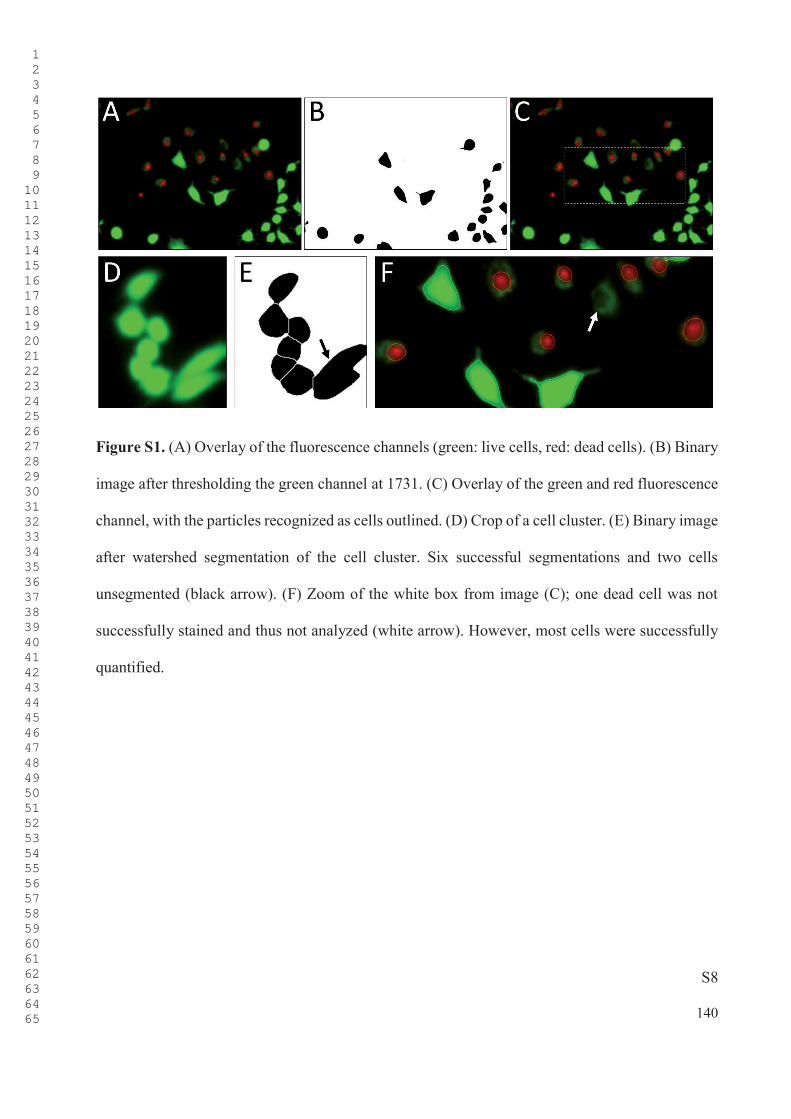
S8
Figure S1. (A) Overlay of the fluorescence channels (green: live cells, red: dead cells). (B) Binary
image after thresholding the green channel at 1731. (C) Overlay of the green and red fluorescence
channel, with the particles recognized as cells outlined. (D) Crop of a cell cluster. (E) Binary image
after watershed segmentation of the cell cluster. Six successful segmentations and two cells
unsegmented (black arrow). (F) Zoom of the white box from image (C); one dead cell was not
successfully stained and thus not analyzed (white arrow). However, most cells were successfully
quantified.
1 2 3 4 5 6 7 8 9 1011121314151617181920212223242526272829303132333435363738394041424344454647484950515253545556575859606162636465 140
S9
1.9. Complement Activation Testing
Assessment of the complement-activating properties was performed on full Ti-substrates, as glass
is known to activate the complement system.[3] A commercial ELISA kit (C5a DuoSet) by Bio-
Techne GmbH (Wiesbaden, Germany) was applied to detect human C5a, a protein fragment
released from the complement component C5 upon activation. The colorimetric assay was
performed in a 96-well format and each individual condition was analyzed as triplicate, according
to the provided description. The TiO2-substrate and surfaces 1, 2, and 3 were then incubated with
PRP for 0 – 5 h, and samples were taken from the PRP at t = 0, 30 min, and at 1, 2, 3, 4, and 5 h.
As a negative control, PRP was incubated in petri dishes without further substrates. As a positive
control, PRP with zymosan from Saccharomyces cerevisiae purchased from Sigma Aldrich
(Darmstadt, Germany) was incubated in a petri dish. For analysis, the samples were diluted 50-
fold with the provided reagent diluent (1% bovine serum albumin (BSA) in PBS), and
subsequently the absorbance of the diluted samples was measured at 450 nm and 570 nm, using a
microplate reader by Tecan Group Ltd. (Männedorf, Switzerland). The C5a levels were determined
in comparison to an evaluated linear regression of the standardized values.
1.10. Platelet Activation Testing
Petri dishes containing the TiO2-substrate or surface 1, 2, or 3 were incubated with PRP at 37 oC
for 3 h, while shaking on a laboratory shaker (at 50 rpm) to prevent sedimentation. Next, the
substrates were gently washed with PBS (3x) and immerged in a glutaraldehyde solution (2.5% in
Milli-Q) for 1 h at room temperature. Subsequently, the substrates were gradually dehydrated by
submerging the substrates in EtOH/H2O mixtures of v/v= 50/50, 70/30, and 100/0, for 15 min per
1 2 3 4 5 6 7 8 9 1011121314151617181920212223242526272829303132333435363738394041424344454647484950515253545556575859606162636465 141

S10
solution. The substrates were then gold sputtered prior to SEM analysis. In subsequent SEM
analysis, the activated platelets were observed as irregularly spread out structures on the surfaces,
whereas inactivated platelets remained in their spherical shape.
1.11. The Stagnation-Point Flow Model
Whole blood was drawn from a healthy male donor and collected into a citrate vacutainer tube. A
solution of quinacrine dihydrochloride (25 μmol, 1.25 mM) (i.e., a fluorescent dye) in PBS (20 ml,
10 mM, pH 7.4) was prepared, and subsequently gently mixed with the drawn blood (50 μl per ml
blood). Prior to every measurement, the flow chamber and tubing were filled with PBS-solution,
and all air bubbles were removed from the system. Subsequently, blood was infused into the
system at 40 ml/h, by means of a PHD ULTRA syringe pump by Harvard Apparatus (Holliston,
Massachusetts, USA). Upon entering the system, the blood was mixed (in a custom-made mixing
chamber for laminar flow systems) with a solution of adenosine diphosphate (ADP) in PBS-
solution (200 μmol/l), which reactivated the previously anticoagulated blood and stimulated the
platelets to accumulate. Next, the whole blood entered the flow chamber, which consisted of (1) a
top plate with an inflow tube (diameter 600 μm) made of stainless steel, (2) and a lower ring of
stainless steel, and (3) holding a transparent TiO2-coated glass cover slip on which the platelets
accumulated. The lower ring and the cover glass were sealed with a (4) silicone-sealing ring
(Figure S2). PU and PDMS spin-coated glass cover slips were utilized as reference materials. The
blood entered the flow chamber in the center of the top plate, resulting in a stagnation point laminar
flow over the coated cover slip. The flow chamber was irradiated with a 50 W mercury vapor lamp
equipped with a filter block, both purchased from Leica (Wetzlar, Germany). The filter block
permitted wavelengths of 355-425 nm to pass, resulting in visualization of the dyed platelets by
1 2 3 4 5 6 7 8 9 1011121314151617181920212223242526272829303132333435363738394041424344454647484950515253545556575859606162636465 142

S11
fluorescence. Platelet adhesion onto the bottom plate of the flow chamber was observed with a
Fluovert FU-inverted microscope also purchased from Leica. A DFK 33U X 250 camera by
Imaging Source (Bremen, Germany) was attached to the microscope for the visual recording of
the adhesion process. The camera recorded with a resolution of 2048 x 2048, a frame rate of 1/s
and a 925 ms exposure time.
Figure S2. Schematic representation of the stagnation point flow model. (1) The top plate with
inlet and outlet. (2) The stainless steel bottom plate. (3) The transparent (coated) cover slip on
which the platelet adhesion was visualized. (4) A silicon ring to seal the system.
1.12. TAMRA-Amine Post-Functionalization
Special Ti-substrates (covered with a natural TiO2-layer) provided by Berlin Heart GmbH were
MI-dPG coated according to the method described in Section 1.3. Subsequently, a TAMRA-amine
solution (0.01 mg/ml) in MOPS (0.1 M, pH 8.5) was suspended on the MI-dPG-coated substrates,
and the surfaces were incubated overnight at 50 oC. Next, the substrates were incubated with
deionized H2O for 48 h to remove all non-bound TAMRA-amine. Finally, the surfaces were
washed thoroughly with deionized H2O (3x) and EtOH (3x) and dried by means of a N2 flow. As
1 2 3 4 5 6 7 8 9 1011121314151617181920212223242526272829303132333435363738394041424344454647484950515253545556575859606162636465 143

S12
negative control, the experiments were repeated with the bare (uncoated) substrates. No
fluorescence was observed for the TAMRA-amine-incubated Ti-substrate after incubation of the
surface with deionized water. For coating visualization, the TAMRA-amine-incubated substrates
were immerged in PBS, to enhance the photo-active properties of the coating. Additionally,
immerging the samples in PBS reduced reflection artifacts. The uniformity of the coating was
evaluated by imaging the components in a Lumina II fluorescence imager by Perkin Elmer
(Waltham, Massachusetts, USA) using Living Image 3.1 acquisition software. The excitation light
was generated using a xenon lamp with a 500-550 nm excitation filter. Additionally, a 575-650
nm emission filter was used.
Figure S3. A fluorescence image of bare Ti-substrates and MI-dPG-coated Ti-substrates,
incubated with TAMRA-amine at various concentrations. The white circles represent the
1 2 3 4 5 6 7 8 9 1011121314151617181920212223242526272829303132333435363738394041424344454647484950515253545556575859606162636465 144

S13
substrates. For sample VI the fluorescence intensity was so high that the substrate could not be
observed. The samples were placed in small petri dishes filled with distilled water (seen as circles
around the substrates), which amplified the fluorescent signal from the substrates. For I till IV: Ti
functionalized with TAMRA-amine in MOPS-buffer at 100 μg/ml, 10 μg/ml, 1 μg/ml, and 0.1
μg/ml, respectively. For V: the bare Ti-substrate. For VI till IX: MI-dPG-coated Ti functionalized
with TAMRA-amine in MOPS at 100 μg/ml, 10 μg/ml, 1 μg/ml, and 0.1 μg/ml. It was clearly
observed that a TAMRA-amine concentration of 10 μg/ml led to fluorescence on the MI-dPG-
coated Ti-substrate, whereas no fluorescence was observed on the bare Ti-substrate.
1.13. VAD Coating Visualization
After coating of the VAD prototype with MI-dPG, as described in Section 1.3. The circulatory
system was filled with a TAMRA-amine solution (0.26 mg, 4.91x10⁻⁴ mmol) in MOPS-buffer (26
ml, 0.1 M, pH 8.5) and the VAD prototype was started at a rotational speed of 90 rpm. The whole
circuit (including the VAD) was then placed in an oven at 50 oC, and the system was left running
for 10 h. Next, the system was removed from the oven, the VAD was stopped, the TAMRA-amine
solution was removed from the system, and the system was rinsed with deionized H2O (3x) and
EtOH (3x). After that, the system was filled with deionized H2O, and the VAD was started at a
rotational speed of 90 rpm. The system was left running for 48 h at room temperature to remove
all non-bound TAMRA-amine. Finally, the VAD was stopped, the deionized H2O was removed
from the circuit, the VAD was additionally dried under N2-flow, and the VAD was removed from
the circulatory system. The VAD prototype was then dismounted, and its parts were analyzed by
means of fluorescence spectroscopy, as described in Section 1.12.
1 2 3 4 5 6 7 8 9 1011121314151617181920212223242526272829303132333435363738394041424344454647484950515253545556575859606162636465 145

S14
For comparison, one VAD rotor was dip-coated (i.e., static conditions), as described in
Section 1.3. After the MI-dPG coating, the rotor blade was immersed in a TAMRA-amine solution
(0.01 mg/ml) in MOPS (0.1 M, pH 8.5), and the rotor was incubated overnight (ca. 10 h at 50 oC).
Next, the rotor was incubated with deionized H2O for 48 h at room temperature to remove all non-
bound TAMRA-amine. Subsequently, the rotor was washed with deionized H2O (3x) and EtOH
(3x), and dried using a N2-flow.
1 2 3 4 5 6 7 8 9 1011121314151617181920212223242526272829303132333435363738394041424344454647484950515253545556575859606162636465 146

S15
2. SUPPORTING DATA
Table S1. LIVE/DEAD™ Quantification and Morphology assessment of A549 and DF-1
Cells on the Various Substrates.
Cell
TypeSubstrate #ImagesA LiveB DeadB TotalB ViabilityC
Cells /
ImageD
Shape
Factor
A549
TCPS 3
85
136
94
2
4
4
87
140
98
96.9
± 0.9 %
108.3 ±
22.8
0.72
± 0.03
lPG–b–OA11E 3
45
53
30
2
1
3
47
54
33
94.9
± 3.7 %
44.7
± 8.7
0.73
± 0.02
HO–PEG–NH2 E 3
47
37
49
1
1
0
48
38
49
98.4
± 1.4 %
45
± 5.0
0.73
± 0.03
TiO2 4
53
58
71
80
1
1
2
0
54
59
73
80
98.4
± 1.1 %
66.5
± 10.5
0.73
± 0.01
1 2 3 4 5 6 7 8 9 1011121314151617181920212223242526272829303132333435363738394041424344454647484950515253545556575859606162636465 147
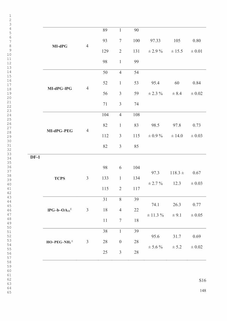
S16
MI-dPG 4
89
93
129
98
1
7
2
1
90
100
131
99
97.33
± 2.9 %
105
± 15.5
0.80
± 0.01
MI-dPG–lPG 4
50
52
56
71
4
1
3
3
54
53
59
74
95.4
± 2.3 %
60
± 8.4
0.84
± 0.02
MI-dPG–PEG 4
104
82
112
82
4
1
3
3
108
83
115
85
98.5
± 0.9 %
97.8
± 14.0
0.73
± 0.03
DF-1
TCPS 3
98
133
115
6
1
2
104
134
117
97.3
± 2.7 %
118.3 ±
12.3
0.67
± 0.03
lPG–b–OA11E 3
31
18
11
8
4
7
39
22
18
74.1
± 11.3 %
26.3
± 9.1
0.77
± 0.05
HO–PEG–NH2 E 3
38
28
25
1
0
3
39
28
28
95.6
± 5.6 %
31.7
± 5.2
0.69
± 0.02
1 2 3 4 5 6 7 8 9 1011121314151617181920212223242526272829303132333435363738394041424344454647484950515253545556575859606162636465 148

S17
TiO2 4
63
59
68
90
0
3
2
2
63
62
71
92
97.5
± 2.0 %
72
± 12.1
0.77
± 0.01
MI-dPG 4
118
153
145
67
3
1
2
2
121
154
147
69
98.2
± 1.0 %
122.8
± 33.4
0.82
± 0.02
MI-dPG–lPG 6
44
6
64
51
56
109
2
0
0
1
8
5
46
6
64
52
64
114
96.1
± 4.7 %
57.7
± 31.9
0.85
± 0.01
MI-dPG–PEG 4
153
113
82
92
1
0
1
1
154
113
83
93
99.3
± 0.5 %
110.8
± 27.2
0.66
± 0.03
(A) The total amount of images taken on the substrate. (B) The amount of live/dead/total cells
observed on a 1.4 x 10⁻³ cm2 portion of the respective substrate. (C) The cell viability calculated
as an average from the various images per substrate-type. (D) The amount of cells observed on a
440 μm x 330 μm fraction of the respective surface. (E) The data observed for TCPS after 24 h of
culturing in the presence of 10 mg/ml lPG–b–OA11 or HO–PEG–NH2.
1 2 3 4 5 6 7 8 9 1011121314151617181920212223242526272829303132333435363738394041424344454647484950515253545556575859606162636465 149
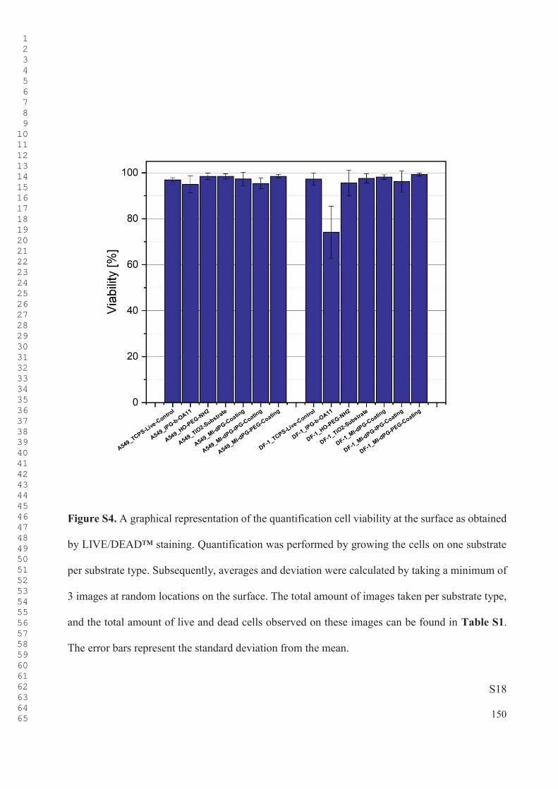
S18
Figure S4. A graphical representation of the quantification cell viability at the surface as obtained
by LIVE/DEAD™ staining. Quantification was performed by growing the cells on one substrate
per substrate type. Subsequently, averages and deviation were calculated by taking a minimum of
3 images at random locations on the surface. The total amount of images taken per substrate type,
and the total amount of live and dead cells observed on these images can be found in Table S1.
The error bars represent the standard deviation from the mean.
1 2 3 4 5 6 7 8 9 1011121314151617181920212223242526272829303132333435363738394041424344454647484950515253545556575859606162636465 150
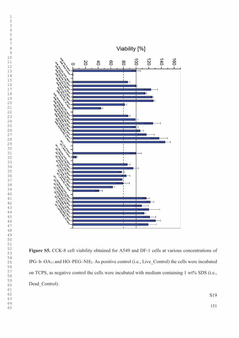
S19
Figure S5. CCK-8 cell viability obtained for A549 and DF-1 cells at various concentrations of
lPG–b–OA11 and HO–PEG–NH2. As positive control (i.e., Live_Control) the cells were incubated
on TCPS, as negative control the cells were incubated with medium containing 1 wt% SDS (i.e.,
Dead_Control).
1 2 3 4 5 6 7 8 9 1011121314151617181920212223242526272829303132333435363738394041424344454647484950515253545556575859606162636465 151

S20
Table S2. Time-Dependent C5a-Concentration in the PRP-Supernatant of Various
Substrates.
Time (h) SubstrateC5a Concentration
(ng/ml)
STDEV
(ng/ml)
0
Prp 1.13 0.06
Zym 1.61 0.10
TiO2 1.73 0.08
1 1.38 0.04
2 0.83 0.08
3 1.20 0.10
0.5 h
Prp 0.85 0.03
Zym 2.68 0.34
TiO2 1.84 0.13
1 2.06 0.08
2 1.44 0.10
3 1.62 0.07
1 h
Prp 0.78 0.02
Zym 3.12 0.13
TiO2 1.53 0.05
1 1.26 0.02
2 1.77 0.06
3 1.49 0.07
1 2 3 4 5 6 7 8 9 1011121314151617181920212223242526272829303132333435363738394041424344454647484950515253545556575859606162636465 152
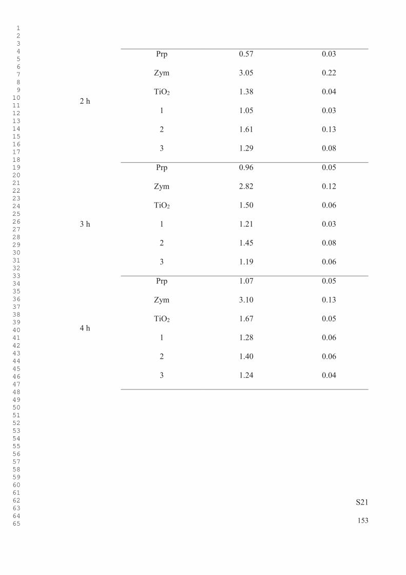
S21
2 h
Prp 0.57 0.03
Zym 3.05 0.22
TiO2 1.38 0.04
1 1.05 0.03
2 1.61 0.13
3 1.29 0.08
Prp 0.96 0.05
Zym 2.82 0.12
TiO2 1.50 0.06
3 h 1 1.21 0.03
2 1.45 0.08
3 1.19 0.06
4 h
Prp 1.07 0.05
Zym 3.10 0.13
TiO2 1.67 0.05
1 1.28 0.06
2 1.40 0.06
3 1.24 0.04
1 2 3 4 5 6 7 8 9 1011121314151617181920212223242526272829303132333435363738394041424344454647484950515253545556575859606162636465 153

S22
5
Prp 0.99 0.06
Zym 3.08 0.12
TiO2 1.61 0.08
1 1.27 0.05
2 1.53 0.09
3 1.23 0.06
Figure S6. Graphical display of the C5a levels in the PRP-supernatant of TiO2 (red) and surfaces
1 (orange), 2 (yellow), and 3 (green). The samples were compared to PRP (light blue) and PRP in
which the complement activation was triggered by adding zymosan from Saccharomyces
cerevisiae (black). The error bars represent the standard deviation from the mean. All
measurements were performed with n = 3.
1 2 3 4 5 6 7 8 9 1011121314151617181920212223242526272829303132333435363738394041424344454647484950515253545556575859606162636465 154

S23
Table S3. Time-Dependent Surface Coverage (in % of the Total Measured Area) of the
Stagnation Point Flow Model for the TiO2-Substrate and Surfaces 1, 2, and 3.
Time (s)
0 30 60 120 180 240
TiO2
0.73%
0.78%
-
1.30%
0.92%
1.03%
1.21%
0.90%
2.82%
1.58%
3.88%
3.95%
2.61%
0.76%
2.00%
1.44%
3.25%
2.16%
4.77%
5.11%
3.46%
0.94%
2.16%
1.49%
3.59%
2.84%
5.48%
6.80%
4.41%
4.20%
2.23%
1.09%
3.60%
-
5.71%
7.70%
5.11%
5.60%
4.43%
-
3.72%
4.82%
6.00%
7.81%
5.80%
6.45%
6.08%
-
1
0.70%
0.95%
0.79%
0.96%
0.81%
1.02%
1.32%
0.61%
-
-
1.35%
1.00%
-
1.13%
0.77%
1.31%
0.94%
1.54%
-
1.37%
1.07%
-
0.98%
1.06%
1.70%
1.21%
1.53%
4.04%
1.30%
1.07%
4.27%
1.48%
1.06%
3.08%
1.73%
1.49%
3.94%
1.89%
2.32%
4.89%
2.15%
1.25%
3.67%
1.82%
1.48%
3.29%
3.65%
2.36%
5.28%
2.46%
3.62%
4.38%
2.01%
1.47%
1 2 3 4 5 6 7 8 9 1011121314151617181920212223242526272829303132333435363738394041424344454647484950515253545556575859606162636465 155

S24
2
0.84%
1.01%
0.43%
0.53%
-
0.53%
0.62%
0.63%
0.50%
0.86%
0.85%
0.43%
0.61%
-
1.15%
0.55%
0.69%
0.54%
0.82%
0.77%
0.50%
0.66%
-
-
0.57%
0.62%
0.52%
0.82%
0.88%
0.50%
0.70%
-
1.82%
0.58%
0.63%
1.18%
0.91%
0.79%
0.43%
0.81%
-
2.15%
0.58%
0.74%
1.82%
0.81%
0.93%
0.44%
0.75%
-
2.39%
0.54%
0.64%
1.88%
3
1.37%
0.77%
-
0.69%
0.71%
0.89%
0.75%
0.62%
1.13%
0.79%
2.77%
4.17%
1.03%
2.44%
2.67%
2.90%
0.71%
2.98%
1.16%
4.08%
5.09%
1.40%
3.52%
4.22%
4.16%
0.69%
4.24%
1.25%
5.27%
5.72%
3.13%
4.77%
6.22%
5.51%
0.83%
5.99%
2.19%
6.57%
6.29%
4.45%
5.54%
6.71%
6.46%
3.24%
6.96%
4.65%
6.91%
6.73%
5.21%
6.36%
7.16%
7.07%
4.55%
7.65%
1 2 3 4 5 6 7 8 9 1011121314151617181920212223242526272829303132333435363738394041424344454647484950515253545556575859606162636465 156

S25
PDMS
1.10%
1.42%
1.00%
0.53%
1.29%
1.76%
-
1.40%
-
3.47%
3.46%
3.45%
-
4.27%
2.46%
4.64%
4.40%
4.59%
4.51%
4.57%
5.11%
3.05%
5.70%
4.21%
5.86%
6.02%
6.84%
5.15%
6.10%
7.09%
4.60%
7.22%
6.21%
7.50%
7.60%
8.27%
-
7.24%
7.17%
5.20%
7.51%
6.67%
7.79%
7.22%
7.73%
-
-
6.87%
-
6.93%
6.49%
6.90%
6.44%
6.42%
PU
0.72%
1.04%
1.82%
3.03%
1.05%
0.84%
1.17%
7.54%
3.72%
3.85%
2.30%
2.60%
4.25%
2.58%
2.51%
4.16%
-
3.95%
4.44%
4.25%
3.22%
4.93%
3.72%
3.24%
5.06%
-
5.16%
5.01%
5.10%
4.03%
6.52%
5.36%
4.26%
6.31%
8.16%
6.19%
5.63%
5.62%
3.95%
7.23%
5.87%
4.85%
7.07%
8.19%
6.62%
6.37%
5.56%
5.27%
7.30%
6.80%
5.37%
6.97%
7.52%
6.60%
1 2 3 4 5 6 7 8 9 1011121314151617181920212223242526272829303132333435363738394041424344454647484950515253545556575859606162636465 157

S26
Collagen
1.27%
0.67%
1.35%
1.34%
0.84%
1.35%
-
0.92%
4.32%
3.23%
4.44%
3.65%
3.96%
3.95%
4.71%
2.83%
5.91%
5.30%
5.99%
5.54%
6.10%
6.29%
6.19%
-
6.95%
7.11%
6.98%
7.42%
8.29%
8.35%
7.34%
6.42%
7.05%
7.61%
7.08%
7.83%
7.70%
7.03%
7.65%
8.45%
6.95%
7.43%
6.91%
-
6.64%
6.37%
7.84%
-
All outliers have been removed from this table. The averages and standard deviations shown in
the publication were calculated from the values at t = 180 s.
3. LITERATURE
[1] M. W. Kulka, I. S. Donskyi, N. Wurzler, D. Salz, Ö. Özcan, W. E. S. Unger, R. Haag, ACS
Applied Bio Materials 2019, 2, 5749.
[2] M. D. Abràmoff, P. J. Magalhães, S. J. Ram, Biophotonics international 2004, 11, 36.
[3] J. Hed, M. Johansson, M. Lindroth, Immunology Letters 1984, 8, 295.
1 2 3 4 5 6 7 8 9 1011121314151617181920212223242526272829303132333435363738394041424344454647484950515253545556575859606162636465 158

4.3. Surface-initiated Grafting of Dendritic Polyglycerol from
Mussel-inspired Adhesion Layers for the Creation of
Biocompatible Cell-repelling Coatings
Figure 28. Graphical abstract. This figure was reproduced with permission from ref. 281
Copyright © 2020, Wiley-VCH.
Michaël W. Kulka, * Chuanxiong Nie, Philip Nickl, Yannic Kerkhoff, Arushi Garg, Dirk Salz,
Jörg Radnik, Ingo Grunwald, Rainer Haag, * Wiley Adv. Mater. Interfaces 2020, Submitted.
*Corresponding Author
Contributions: M.W.K.: Conceived, planned, and coordinated the project, executed all
synthesis and coating experiments, and performed all CA and SEM measurements. Interpreted
all data and summarized the results, discussions, and conclusions in the form of a scientific
publication.
159

1
Surface-Initiated Grafting of Dendritic Polyglycerol from Mussel-Inspired Adhesion-
Layers for the Creation of Biocompatible Cell-Repelling Coatings
Michaël W. Kulka,a Chuanxiong Nie,a Philip Nickl,a,b Yannic Kerkhoff,a Arushi Garg,a Dirk
Salz,c Jörg Radnik,b Ingo Grunwald,c,d Rainer Haag*,a
a Institute for Chemistry and Biochemistry, Freie Universität Berlin, Takustraße 3, 14195 Berlin,
Germany
b BAM – Federal Institute for Material Research and Testing, Division of Surface Analysis and
Interfacial Chemistry, Unter den Eichen 44-46, 12205 Berlin, Germany
c Fraunhofer Institute for Manufacturing Technology and Advanced Materials IFAM, Wiener
Straße12, 28359 Bremen, Germany
d Hochschule Bremen – City University of Applied Sciences, Department of Industrial and
Environmental Biology, Neustadtswall 30, 28199 Bremen, Germany
KEYWORDS: cell-repelling surface coatings, surface-initiated grafting, mussel-inspired
adhesives, dendritic polyglycerol
Complete Manuscript
1 2 3 4 5 6 7 8 9 1011121314151617181920212223242526272829303132333435363738394041424344454647484950515253545556575859606162636465 160

2
ABSTRACT
Biofouling is a major challenge in the application of textiles, biosensors, and biomedical
implants.[1] In the current work, a straightforward method for the solvent-free polymerization of
antifouling dendritic polyglycerol (dPG) from mussel-inspired dendritic polyglycerol (MI-dPG)
coatings on hydrophilic titanium dioxide (TiO2) and hydrophobic polydimethylsiloxane (PDMS)
is reported. Surface characterization was performed by static water contact angle (CA)
measurements, X-ray photoelectron spectroscopy (XPS), and scanning electron microscopy
(SEM). Significant lower CA values were obtained after dPG grafting from MI-dPG-coated TiO2
and MI-dPG coated PDMS. Furthermore, XPS showed a time-dependent increase of the C–O
bond content upon dPG grafting from MI-dPG-coated TiO2 and MI-dPG-coated PDMS. Analysis
of the surface morphology by SEM showed a clear time-dependent increase in the surface
roughness upon dPG grafting from MI-dPG-coated TiO2 and MI-dPG-coated PDMS. When the
proliferation and viability of two adhesive cell types were studied via LIVE/DEAD™ staining, a
strong reduction in the cell density was observed after the dPG grafting from MI-dPG-coated
TiO2 and MI-dPG-coated PDMS (a decrease of > 95% in all cases). Additionally, the cell
viability was found to be high (> 88%). The combined results showed the biocompatibility and
highly cell-repelling surfaces of dPG from MI-dPG-coated TiO2 and MI-dPG-coated PDMS.
INTRODUCTION
Unspecific biofouling is a considerable challenge in the application of medical implants,
biosensors, and other surgical and protective equipment in hospitals. For example, biofouling can
lead to deterioration of the surface, and increases the risk of infectious contamination and
thrombosis (e.g., in case of joint prosthesis, urinary catheters, and intravenous stents).[2]
1 2 3 4 5 6 7 8 9 1011121314151617181920212223242526272829303132333435363738394041424344454647484950515253545556575859606162636465 161

3
Furthermore, biofouling is encountered in marine applications, where it is the cause of high
expenses resulting from fouling-related decreased fuel efficiency.[3] Additionally, the metabolic
activity of the attached organisms can cause local corrosion, thus creating further costs.[4] Many
projects have focused on the development of long-term stable non-fouling surface coatings for
industrial-, marine-, and biomedical-applications. The immobilization of hydrophilic polymeric
substances has proven itself as an effective strategy for the introduction of antifouling surface
properties.[5] The mechanism underlaying the fouling-resistance of hydrophilic polymer coatings
is based on the formation of a surface hydration layer in the absence of net charge. This
hydration layer acts as a physical barrier for the prevention of unspecific protein-fouling, and
furthermore prevents cellular- and bacterial- adhesion.
Many methods for the surface-immobilization of polymeric substances have been
developed, including but not limited to: the use of polymeric layer-by-layer assemblies,[6]
irradiation-mediated grafting,[7] Langmuir-Blodgett deposition,[8] and the use of electrostatic or
hydrophobic adsorption.[9] Additionally, thiol- and silane-chemistry are classically used for the
functionalization of noble metals and hydroxylated surfaces, respectively.[10] Although these
methods can be applied to a wide variety of substrates, most of these processes require complex
machinery and/or specific chemical or physical properties of the support material, thus limiting
their application. Therefore, there is a need for the development of straight-forward surface-
functionalization procedures, for the facile functionalization of a wide range of substrate-types.
An interesting alternative for the immobilization of polymeric substances is the use of mussel-
inspired surface chemistry. Mussels can rapidly adhere to virtually every type of organic or
inorganic surface under wet conditions, even to substrates that are classically categorized as
adhesion resistant (e.g., polytetrafluoroethylene (PTFE)).[11] Mussels adhere themselves to the
1 2 3 4 5 6 7 8 9 1011121314151617181920212223242526272829303132333435363738394041424344454647484950515253545556575859606162636465 162

4
surface via an adhesive plaque that is excreted by the mussels’ foot at the end of the byssal
threads.[12] Earlier works showed the high prevalence of the catechol-containing amino acid L-
DOPA and the amine-containing amino acid L-lysine in the mussel foot proteins (Mfps) that are
excreted close to the substrate (i.e., mainly Mfp-5).[12] Based on these findings, Waite et al.
hypothesized the essence of the catechol moieties in the substrate-independent binding character
of some of the Mfps.[13] Later works confirmed the adhesion of catechols to a broad range of
substrates via the formation of hydrogen-bonds, via π–π stacking, via the formation of
coordination complex structures, and via the formation of Michael adducts and Schiff bases
under oxidizing conditions.[14] The reversible surface binding of the catechols via the formation
of complex structures was found to be especially strong in case of titanium dioxide (TiO2)
substrates, with a single molecule interaction force of ca. 800 pN.[15]
In 2007, Messersmith et al. hypothesized that the high prevalence of amine and catechol
functional groups in the Mfps could contribute to the rapid adhesion of mussels.[16] Therefore,
dopamine was selected as a small molecule containing both amine and catechol functionalities.
When dopamine-containing solutions were buffered to a basic pH, auto-oxidation of the catechol
moieties to their respective o-quinone forms occurred. Subsequently, a series of polymerizing
reactions occurred, which finally led to the formation of polydopamine (PDA) coatings on a
wide variety of substrates. The PDA coating was easily post-functionalized with amine- or thiol-
containing secondary reagents via straightforward dip coating procedures, introducing specific
surface properties. As a result of its substrate-independent applicability and facile post-
functionalization, the PDA coating has gained a lot of interest in the field of biomaterials, e.g.,
PDA has been applied in bone and tissue engineering, for the introduction of antimicrobial
activity to the surface, in the creation of surfaces with patterned cell adhesion, and for the
1 2 3 4 5 6 7 8 9 1011121314151617181920212223242526272829303132333435363738394041424344454647484950515253545556575859606162636465 163

5
introduction of anticoagulant surface properties.[17] Although PDA has proven itself as a useful
tool for surface functionalization, the initial coating procedure suffered from slow
polymerization rates and a limited coating thickness.[16] Additionally, resulting from its dark-
brown to black color, the PDA coatings is unsuitable for various optical applications.[16] Various
methods for the acceleration of the polymerization reaction of PDA have been developed, but
most of these methods utilize toxic agents to enhance the polymerization rate.[18] Therefore, there
is a further need for the development of substrate-independent coating materials for the
introduction of tailored surface properties.
In 2014, Wei et al. developed mussel-inspired polyglycerol (MI-dPG), which did not only
contain the functional groups that are commonly found in Mfps, but also mimicked the
molecular structure and weight of Mfps (Figure 1).[19] Polymerization of MI-dPG under slightly
basic conditions led to the rapid formation of substrate-independent coatings with a controllable
coating roughness and thickness (up till 4 μm after 4 hours of coating).[19] Furthermore, the
coatings appeared transparent at low coating thickness. Earlier works by our group have shown
the facile post-functionalization of the MI-dPG coating with nanoparticles and amine-containing
secondary reagents, for the introduction of antifouling and antibacterial surface properties.[20]
Furthermore, the amine moieties of the MI-dPG coating have been utilized for the
immobilization of acyl chloride-containing secondary reagents.[21]
In the current scientific literature, the immobilization of poly(ethylene glycol) (PEG) is
often considered as the gold standard for the creation of antifouling surface coatings.[22] For
instance, in Messersmith’s initial work on PDA, cell-repelling surface properties were introduced
to the surface via the covalent grafting of thiol- or amine-terminated methoxy-PEG (mPEG) onto
PDA coatings.[16] Unfortunately, PEG suffers from issues considering instability upon heating in
1 2 3 4 5 6 7 8 9 1011121314151617181920212223242526272829303132333435363738394041424344454647484950515253545556575859606162636465 164

6
air,[23] and immunological recognition upon repeated exposure.[24] Therefore, there is a need for
the development of hydrophilic antifouling surface coatings that show similar or better
antifouling properties than PEG, while showing higher biocompatibility and oxidative/thermal
stability than PEG under physiological conditions. The use of dendritic polyglycerol (dPG)
offers an interesting alternative for the creation of antifouling coatings. An earlier work by
Siegers and coworkers showed the higher oxidative stability of bulk dPG in comparison to
PEG.[25] Additionally, multiple projects showed that the immobilization of dPG on the substrate
leads to the creation of antifouling surfaces.[25-26] Although these approaches clearly illustrated
the antifouling potency of dPG, most of them required multistep functionalization of the dPG-
core prior to surface functionalization, thus leading to high production costs. Khan et al. and
Moore et al. gave alternative approaches that both grafted dPG directly from silica (Si)-based
substrates.[27] However, both approaches required the use of the highly reactive caustic base
sodium methoxide.[27] A method reported by Weber et al. showed the grafting of dPG from
aluminum, steel, and silicon surfaces without the use of a base. However, the grafting reactions
were performed in an organic solvent, and the substrates required the introduction of
–OH moieties to the surface prior to the grafting process.[28] In the current work, the surface-
bound amines of the MI-dPG coating were utilized to initiate ring-opening polymerization of
bulk glycidol (i.e., in a solvent-free procedure) under elevated temperatures (i.e., to graft dPG
from the MI-dPG coating) (Figure 1). By following this strategy, the direct grafting of
antifouling dPG from the surface was extended to a wide variety of substrates, resulting from the
substrate-independent adhesion character of the MI-dPG coating. In the presented work,
hydrophilic titanium dioxide and hydrophobic PDMS were used as substrate materials. These
materials were selected because of their relevance in biomedical applications. Furthermore, these
1 2 3 4 5 6 7 8 9 1011121314151617181920212223242526272829303132333435363738394041424344454647484950515253545556575859606162636465 165

7
materials showed large variations in their chemical and physical surface properties. Therefore,
the functionalization of these materials provided a proof-of-concept for the substrate-independent
applicability of the novel method presented in this work. It was hypothesized that the thickness
and morphology of the grafted dPG-layer would vary as a function of the reaction time and
temperature. Furthermore, it was foreseen that the introduction of the dPG-layer would lead to
the formation of a tightly bound surface hydration layer that would function as a physical barrier
for the prevention of cell-adhesion.[27-28]
1 2 3 4 5 6 7 8 9 1011121314151617181920212223242526272829303132333435363738394041424344454647484950515253545556575859606162636465 166

8
Figure 1. (A) A schematic representation of the molecular structure of MI-dPG. The shown
structure is an idealized molecular structure; the number of glycerol monomer (shown within the
yellow sphere) varies with the size of the polymer. The dPG-core shows ~55% branching.[29] The
catechol moieties are depicted in red. The amine moieties are depicted in blue. (B) A schematic
representation of the dip coating of TiO2 and PDMS substrates with MI-dPG. (C) The various
ways in which catechols can adhere to the surface. (I) On surfaces that contain hydrogen bond
donors/acceptors, catechols can adhere via hydrogen bond formation, (II) on surfaces that
contain aromatic systems, catechols can bind via π–π interactions, (III) catechols can tether to
certain metal oxide surfaces (especially TiO2) via the formation of strong but reversible metal
complexes, (IV) finally, catechols can irreversibly bind to amine (and thiol) functionalized
surfaces via the formation of Michael adducts and Schiff bases.[14] (D) A schematic
representation of the grafting process performed in this work. After the coating of TiO2 and
PDMS with MI-dPG, the MI-dPG coating was utilized as a macro-initiator for the thermally
induced ring-opening polymerization of glycidol from the surface (i.e., the grafting of dPG).
RESULTS AND DISCUSSION
First, transparent TiO2-coated substrates were produced according to Section 1.2.1. of the
Electronic Supplementary Information (ESI) (i.e., a transparent model coating with the surface
properties of bulk titanium). Subsequently, these substrates were functionalized with MI-dPG,
according to a modified version of the dip coating method that was earlier described by Wei and
coworkers (Sections 1.1.4. and 1.2.3. of the ESI).[19] After dip coating, the MI-dPG-coated
surfaces were put in a substrate holder in a custom made flask at 110 °C under high vacuum for
> 10 h (from now on referred to as TiO2–MI-dPG110 °C, HV) (Figure S1 of the ESI), ensuring that
1 2 3 4 5 6 7 8 9 1011121314151617181920212223242526272829303132333435363738394041424344454647484950515253545556575859606162636465 167

9
all solvent was removed from the coatings prior to the grafting process. Interestingly, this drying
process led to an increase in the CA, when the coatings were compared to MI-dPG coatings that
were dried under atmospheric pressure for one hour at 50 °C (from now on referred to as TiO2–
MI-dPG50 °C, ATM) (Figure S3 and Table S1 of the ESI). This observation was explained by
further intra-layer crosslinking of the MI-dPG coating under elevated temperatures and high
vacuum, effectively leading to the loss of free amines, therefore effectively making the coating
less hydrophilic. Analysis of TiO2–MI-dPG50 °C, ATM by X-ray photoelectron spectroscopy (XPS)
showed a 1.35 : 1 ratio of C–O to C–C bonds (Figure 3A and Tables S3 and S4 of the ESI),
which was roughly in line with an earlier work of our group.[20a] For TiO2–MI-dPG110 °C, HV the
C–O bond content of the MI-dPG coating slightly decreased to a 1.09 : 1 ratio of C–O to C–C
bonds. Additionally, the N1s’ elemental content observed for TiO2–MI-dPG50 °C, ATM was clearly
higher than the N1s’ elemental content observed for TiO2–MI-dPG110 °C, HV (7.3 atomic percent
(at.%) and 5.8 at.%, respectively) (Figure 3C and Figure S5 and Table S5 of the ESI). This
observation was explained by the occurrence of additional Michael-type addition reactions and
the formation of Schiff bases between the o-quinones and free amines present in the MI-dPG
coating under vacuum at elevated temperatures. A slightly higher Ti2p content was observed for
TiO2–MI-dPG110 °C, HV than for TiO2–MI-dPG50 °C, ATM (0.8 at.% and 0.6 at.%, respectively),
indicating that the coating decreased its thickness as a result of the drying process at elevated
temperatures under reduced pressure (Figure 3C and Figure S5 and Table S5 of the ESI). The
combined results suggest the additional crosslinking and shrinkage of the coating upon heating at
elevated temperatures under vacuum conditions. This additional crosslinking might contribute
positively to the stability of the MI-dPG coating on the surface. All coatings further discussed in
1 2 3 4 5 6 7 8 9 1011121314151617181920212223242526272829303132333435363738394041424344454647484950515253545556575859606162636465 168

10
this work were polymerized from MI-dPG coatings that were previously dried at 110 °C under
high vacuum conditions.
To determine the optimal dPG grafting time and temperature (i.e., the time and
temperature that would result in the lowest CA), glycidol was grafted from TiO2–MI-dPG for t =
30 min, 1 h, 3 h, and 24 h at 80 °C, 100 °C, and 120 °C (from now on referred to as
TiO2–MI-dPG@dPGΔt, T, with Δt = reaction time and T = reaction temperature) (Section 1.2.4. of
the ESI). A time- and temperature-dependent decrease of the CA was clearly observed after the
grafting of dPG from the MI-dPG-coated substrates (Figure 2A, 2B, and Figure S4 and Table
S2 of the ESI). CA measurements showed surface wetting for TiO2–MI-dPG@dPG3 h, 100 °C and
TiO2–MI-dPG@dPG24 h, 80 °C (Figure 2A, 2B, and Figure S4 and Table S2 of the ESI).
Interestingly, when the grafting process was performed at 120 °C the CA reached ca. 25°, i.e., no
surface wetting was observed. This observation was explained by a synergetic effect between the
surface roughness and the hydrophilic surface chemistry in case of TiO2–MI-dPG@dPG3 h, 100 °C
and TiO2–MI-dPG@dPG24 h, 80 °C, significantly lowering the CA obtained for these substrates.
When the grafting process was performed at higher reaction temperatures or with longer reaction
times, the (nanometer-sized) surface roughness was potentially lost as a result of excessive dPG
grafting. Consequently, CA values that are common for polyglycerol monolayer coatings were
observed in case of longer grafting times with high reaction temperatures.[25] The combined
results showed the successful grafting of dPG from the MI-dPG coated TiO2 substrate.
As a control, bare TiO2 substrates were incubated with glycidol for t = 30 min, 1 h, 3 h,
and 24 h at 100 °C (from now on referred to as TiO2@dPGΔt, 100 °C) (Section 1.2.4. of the ESI).
CA measurements of TiO2@dPGΔt, 100 °C showed a time-dependent decrease in the CA, which
was explained by the grafting of dPG from hydroxyl moieties present on the TiO2 substrates
1 2 3 4 5 6 7 8 9 1011121314151617181920212223242526272829303132333435363738394041424344454647484950515253545556575859606162636465 169

11
(Figure 2A, 2B, and Figure S4 and Table S2 of the ESI). The results observed for the bare TiO2
were in line with an earlier work by Weber and coworkers.[28] Nevertheless, surface wetting was
not observed for TiO2@dPGΔt, 100 °C. Furthermore, the CA value obtained for TiO2@dPG3 h, 100 °C
clearly exceeded the CA-value obtained for TiO2–MI-dPG@dPG3 h, 100 °C (51° ± 4° and surface
wetting, respectively), indicating that the grafting process was insufficient in absence of the
MI-dPG coating (Figure 2A, 2B, and Figure S4 and Table S2 of the ESI).
Figure 2. (A) A graphical representation of the CA obtained for TiO2 (Green),
TiO2–MI-dPG@dPGΔt, 80 °C (Black), TiO2–MI-dPG@dPGΔt, 100 °C (Red), and
TiO2–MI-dPG@dPGΔt, 120 °C (Blue) as a function of the time (in minutes). The dotted black line
represents the CA obtained for a polyglycerol monolayer on gold.[25] All measurements
were performed as triplicates; the error bars represent the standard deviation from
the mean. (B) The CA images obtained for TiO2, TiO2@dPG3 h, 100 °C, TiO2–MI-dPG, and
TiO2–MI-dPG@dPG3 h, 100 °C. The shown CA values were obtained from measurements that were
1 2 3 4 5 6 7 8 9 1011121314151617181920212223242526272829303132333435363738394041424344454647484950515253545556575859606162636465 170

12
performed in triplicate. The shown error reflects the standard deviation from the mean. (i):
coating with MI-dPG, (ii): drying under high vacuum at 110 °C.
When the grafting process was characterized by means of XPS, a time-dependent
increase of the C–O bond content was observed for TiO2–MI-dPG@dPGΔt, T with T = 80 °C,
100 °C, or 120 °C and TiO2@dPGΔt, 100 °C. However, for TiO2@dPGΔt, 100 °C the C–O bond
content increased only slowly, whereas high C–O contents were already observed after 30 min of
dPG grafting for all MI-dPG-coated systems at all tested temperatures (Figure 3B, and Tables
S6 and S7 of the ESI). These observations further confirmed that the MI-dPG coating accelerated
the dPG grafting process. Additionally, for TiO2–MI-dPG@dPGΔt, T, it was observed that the
C–O content (and thus the dPG-layer) increased quicker when the dPG grafting was performed at
higher temperatures (Figure 3B and Tables S6 and S7 of the ESI). When the elemental contents
of titanium (i.e., the Ti2p elemental content) and nitrogen (i.e., the N1s elemental content) were
investigated by means of XPS, a time-dependent decrease in the Ti2p content was observed for
TiO2@dPGΔt, 100 °C, which indicated the successful grafting of dPG from the surface (Figure S5
and Table S8 of the ESI). However, the Ti2p content remained high for TiO2@dPG30 min, 100 °C,
TiO2@dPG1 h, 100 °C, and TiO2@dPG3 h, 100 °C, showing that the dPG grafting process occurred
only slowly on the bare TiO2 control (Figure S5 and Table S8 of the ESI). Only after 24 hours
of dPG grafting, the Ti2p elemental content was clearly reduced on the bare TiO2-substrate
(Figure S5 and Table S8 of the ESI). When the elemental compositions of
TiO2–MI-dPG@dPGΔt, T were assessed by means of XPS, low but measurable Ti2p elemental
contents were observed for TiO2–MI-dPG and for TiO2–MI-dPG@dPGΔt, 80 °C with Δt = 30 min,
1 h, or 3 h (Figure S5 and Table S8 of the ESI). Only after 24 h of dPG grafting no Ti2p content
1 2 3 4 5 6 7 8 9 1011121314151617181920212223242526272829303132333435363738394041424344454647484950515253545556575859606162636465 171

13
was observed for TiO2–MI-dPG@dPG24 h, 80 °C. In case of TiO2–MI-dPG@dPGΔt, T with T =
100 °C or 120 °C, the Ti2p signal was already non-observable after 1 h of dPG grafting,
indicating that the dPG-layer was already thick enough (i.e., > 10 nm) to completely suppress the
Ti2p signal (Figure 3C, and Figure S5 and Table S8 of the ESI), i.e., showing that the grafting
process occurred quicker at higher temperatures.
The speed of the dPG grafting process from the MI-dPG-coated TiO2 substrates could
also be followed by monitoring the N1s elemental content (the N1s signal originated from the
amines present in the MI-dPG coating): a time-dependent decrease of the N1s content was
clearly observed as a function of the reaction time, which indicated the grafting of the dPG-layer
from the MI-dPG coating (Figure 3C, and Figure S5 and Table S8 of the ESI). Furthermore, it
was observed that at higher temperatures the N1s signal decreased faster than at lower
temperatures, which showed that the dPG grafting process occurred the fastest at 120 °C (Figure
S5 and Table S8 of the ESI).
Many works have shown the relation between surface wettability and antifouling surface
properties (i.e., protein and cell-repelling properties) for hydrophilic non-charged polymeric
coatings.[5] In the present work, the combined results showed the successful grafting of
hydrophilic antifouling dPG from MI-dPG-coated TiO2 at all tested temperatures, and the lowest
CA values were obtained for TiO2–MI-dPG@dPG3 h, 100 °C and TiO2–MI-dPG@dPG24 h, 80 °C.
1 2 3 4 5 6 7 8 9 1011121314151617181920212223242526272829303132333435363738394041424344454647484950515253545556575859606162636465 172

14
Figure 3. (A) Highly resolved C1s spectra of TiO2, TiO2–MI-dPG50 °C, ATM, and
TiO2–MI-dPG110 °C, HV. (B) Highly resolved C1s spectra of TiO2@dPGΔt, 100 °C,
TiO2–MI-dPG@dPGΔt, 80 °C, TiO2–MI-dPG@dPGΔt, 100 °C, and TiO2–MI-dPG@dPGΔt, 120 °C. (C)
The Ti2p (red) and N1s (blue) content of (I) the bare TiO2-substrate, (II) TiO2–MI-dPG50 °C, ATM,
1 2 3 4 5 6 7 8 9 1011121314151617181920212223242526272829303132333435363738394041424344454647484950515253545556575859606162636465 173

15
(III) TiO2–MI-dPG110 °C, HV (IV) TiO2–MI-dPG@dPG30 min, 100 °C, (V) TiO2–MI-dPG@dPG1 h,
100 °C, (VI) TiO2–MI-dPG@dPG3 h, 100 °C, (VII) TiO2–MI-dPG@dPG24 h, 100 °C. (D)
the XPS spectra obtained for PDMS, PDMS@dPG3 h, 100 °C, PDMS–MI-dPG, and
PDMS–MI-dPG@dPG3 h, 100 °C.
To show the wider applicability of the developed dPG grafting process, hydrophobic
polydimethylsiloxane (PDMS) was coated with MI-dPG (from now on referred to as
PDMS–MI-dPG) and subsequently incubated with glycidol (Sections 1.2.2., 1.2.3., and 1.2.4. of
the ESI). As industrial applications favor solvent-free reactions with short reactions times (i.e.,
enhancing productivity while lowering production costs), PDMS–MI-dPG was only incubated
with glycidol under the optimized reaction conditions which were obtained from the dPG
grafting from TiO2–MI-dPG (i.e., 3 h at 100 °C). As a control, bare PDMS was incubated with
glycidol under identical conditions. Analysis of PDMS@dPG3 h, 100 °C by means of CA
measurements showed no significant change in the wetting characteristics of the PDMS surface
after the dPG grafting process, which indicated that dPG was insufficiently grafted from the bare
PDMS surface (Figure 2C). The CA obtained for the PDMS–MI-dPG surface showed a slightly
decreased wetting character in comparison to the bare PDMS substrate, which was explained by
the combination of the intrinsic hydrophobic character of PDMS (initial CA: 108° ± 4°) and the
roughness introduced to the PDMS surface by the MI-dPG coating (Figure 2C). When
PDMS–MI-dPG was subsequently incubated with glycidol, a clear decrease in the CA was
observed (CA for PDMS–MI-dPG@dPG3 h, 100 °C: 27° ± 6°), which was explained by the
successful grafting of dPG from the MI-dPG coating (Figure 2C). Analysis of the bare PDMS
substrate by means of XPS showed the high prevalence of a Si–C bond content and the absence
1 2 3 4 5 6 7 8 9 1011121314151617181920212223242526272829303132333435363738394041424344454647484950515253545556575859606162636465 174
16
of C–O bonds (Figure 3D and Tables S9 and S10 of the ESI).[30] When PDMS was incubated
with glycidol at 100 °C for 3 h, only a slight increase in the C–O content was observed, which
further indicated the insufficient grafting of dPG from the bare PDMS substrate (Figure 3D, and
Tables S9 and S10 of the ESI). When PDMS–MI-dPG was assessed by means of XPS, the
highly resolved C1s spectrum showed the slight presence of C–O content (Figure 3D, and
Tables S9 and S10 of the ESI), which was explained by the formation of the MI-dPG coating on
PDMS. Analysis of PDMS–MI-dPG@dPG3 h, 100 °C showed a clear increase in the C–O content in
respect to the PDMS–MI-dPG substrate (Figure 3D, and Tables S9 and S10 of the ESI),
indicating the successful grafting of dPG from the MI-dPG coating on PDMS. When the
elemental contents of silicon (i.e., the Si2p elemental content) and nitrogen (i.e., the N1s
elemental content) were assessed for the various PDMS-based systems by means of XPS, a high
Si2p signal was observed for the bare PDMS substrate (23.1 at.%) (Figure S6 and Table S11 of
the ESI). After incubation with glycidol at 100 °C for 3 h, the Si2p signal did only show a minor
change (Si2p content for PDMS@dPG3 h, 100 °C: 22.7 at.%), which indicated that dPG was
insufficiently grafted from the bare PDMS substrate (Figure S6 and Table S11 of the ESI).
Analysis of the elemental content of the PDMS–MI-dPG substrate showed a clear reduction in
the Si2p content (13.5 at.%) (Figure S6 and Table S11 of the ESI). Additionally, the N1s
content increased from 0.1 at.% for bare PDMS to 1.4% for PDMS–MI-dPG (Figure S6 and
Table S11 of the ESI). The combined results indicated the successful formation of the MI-dPG
coating on PDMS. After the grafting of dPG from the PDMS–MI-dPG substrate, the Si2p
content further decreased (to 7.5 at.% for PDMS–MI-dPG@dPG3 h, 100 °C), indicating the
successful formation of the dPG layer on top of the MI-dPG layer (Figure S6 and Table S11 of
the ESI). Additionally, the N1s content decreased when compared to the PDMS–MI-dPG (to 0.3
1 2 3 4 5 6 7 8 9 1011121314151617181920212223242526272829303132333435363738394041424344454647484950515253545556575859606162636465 175

17
at.% for PDMS–MI-dPG@dPG3 h, 100 °C), further confirming the successful grafting of dPG
(Figure S6 and Table S11 of the ESI).
When the surface morphology of the dPG grafting process was investigated by means of
scattering electron microscopy (SEM), it was clearly observed that the MI-dPG coating
introduced roughness in the micrometer range to the bare TiO2 and PDMS substrates (Figures
4A, 4C, 4E and 4G). This observation was in line with earlier works of our group.[19-20, 31] When
the MI-dPG-coated substrates were subsequently incubated with glycidol at 100 °C for 3 h, a
further increase in the surface roughness was clearly observed (Figures 4F and 4H). In the case
of TiO2–MI-dPG@dPG3 h, 100 °C, the grafted dPG appeared as merging smeared out micrometer-
sized particles. For PDMS–MI-dPG@dPG3 h, 100 °C, the grafted particles appeared less smeared
out, indicating that the dPG grafting process from PDMS–MI-dPG might have occurred slower
than from the TiO2–MI-dPG substrate. Nevertheless, in both cases the SEM images clearly
showed the successful grafting of dPG from the MI-dPG adhesive layer. When the bare TiO2
substrate was incubated with glycidol at 100 °C for 3 h, some particles were observed on the
surface (Figure 4B). However, the obtained SEM images clearly showed the enhanced grafting
of dPG in the presence of the MI-dPG coating. When bare PDMS was incubated with glycidol
under elevated temperatures, no clear changes in the surface morphology were observed (Figure
4D). For additional images of the dPG grafting process from TiO2, TiO2–MI-dPG, PDMS, and
PDMS–MI-dPG (showing additional grafting times and temperatures), the reader is referred to
Figures S7 and S8 of the ESI.
1 2 3 4 5 6 7 8 9 1011121314151617181920212223242526272829303132333435363738394041424344454647484950515253545556575859606162636465 176

18
Figure 4. SEM images of the (A) bare TiO2-substrate, (B) the TiO2@dPG3 h, 100 °C,
(C) PDMS, (D) PDMS@dPG3 h, 100 °C, (E) TiO2–MI-dPG, (F) TiO2–MI-dPG@dPG3 h, 100 °C,
(G) PDMS–MI-dPG, and (H) PDMS–MI-dPG@dPG3 h, 100 °C. The shown images are a 3,000x
enlargement of the measured surface.
The proliferation and viability of adhesive human adenocarcinoma cells (A549 cells) and
chicken fibroblast cells (DF-1 cells) were investigated on the various substrates by means of
LIVE/DEAD™ staining (Sections 1.3.1. and 1.3.2. of the ESI). Abundant cell proliferation was
observed for both the A549 and DF-1 cells on tissue culture polystyrene (TCPS) control.
However, the A549 cells showed higher proliferation than the DF-1 cells under the set
incubation conditions (Figures 5A, 6A, and 6B, and Table S12 of the ESI). Nevertheless, both
cell types showed high viability on TCPS (Figure 5A, and Figures 6C, 6D, and Table S12 of
the ESI). Abundant cell proliferation was also observed for both the A549 and DF-1 cells on the
bare TiO2 and PDMS substrates with high cell viabilities (Figures 5B, 5C, 6A, 6B, 6C, and 6D,
1 2 3 4 5 6 7 8 9 1011121314151617181920212223242526272829303132333435363738394041424344454647484950515253545556575859606162636465 177

19
and Table S12 of the ESI). As a control, the proliferation of A549 and DF-1 cells was also
investigated on TiO2@dPG3 h, 100 °C and PDMS@dPG3 h, 100 °C (Figures 5B, 5C, 6A, 6B, 6C, and
6D, and Table S12 of the ESI). For the A549 cells, no significant change in the cell number was
observed for TiO2@dPG3 h, 100 °C, when the substrate was compared to bare TiO2 (Figures 5B and
6A, and Table S12 of the ESI). In contrast, for the DF-1 cells a significant increase in the cell
number was observed on TiO2@dPG3 h, 100 °C (Figures 5C and 6B, and Table S12 of the ESI).
For PDMS@dPG3 h, 100 °C no significant change in the A549 cell number was observed, when
compared to the bare PDMS substrate (Figure 5B and 6A, and Table S12 of the ESI). In
contrast, a significant increase in the DF-1 cell number was observed for PDMS@dPG3 h, 100 °C,
in respect to the bare PDMS substrate (Figures 5C and 6B, and Table S12 of the ESI).
Furthermore, the cells observed on TiO2@dPG3 h, 100 °C and PDMS@dPG3 h, 100 °C showed high
viability (Figures 5B, 5C, 6C, and 6D, and Table S12 of the ESI). The results were explained by
the insufficient grafting of a dPG-layer from the TiO2 surface after 3 h of dPG grafting at 100 °C
(as earlier confirmed by CA measurements, XPS, and SEM), which might have turned the
surface slightly more hydrophilic and more favorable for the adhesion of the
DF-1 cells. As a result, the cells could proliferate on the surface in a similar fashion as on the
bare TiO2 and PDMS substrates. On TiO2–MI-dPG, no significant change in the A549 cell
number was observed, when the substrate was compared to the bare TiO2 substrate (Figures 5B
and 6A, and Table S12 of the ESI). However, the number of DF-1 cells on TiO2–MI-dPG was
found to be significantly higher than for the bare TiO2 substrate (Figures 5C and 6B, and Table
S12 of the ESI). For the PDMS–MI-dPG substrate, similar results were obtained (Figures 5C
and 6B, and Table S12 of the ESI). Besides, the cell viabilities of both cell types were found to
be high on the TiO2–MI-dPG and PDMS–MI-dPG substrates (Figures 5B, 5C, 6C, and 6D, and
1 2 3 4 5 6 7 8 9 1011121314151617181920212223242526272829303132333435363738394041424344454647484950515253545556575859606162636465 178

20
Table S12 of the ESI). Quantification of the A549 and DF-1 cells showed a dramatic decrease in
the cell numbers of both cell types after the grafting of dPG from TiO2–MI-dPG and
PDMS–MI-dPG. In case of TiO2–MI-dPG@dPG3 h, 100 °C, a > 96% reduction of the cell density
was observed for both cell types, when compared to the bare TiO2 substrate (Figures 5B, 6A,
6B, and Table S12 of the ESI). Similar results were obtained for PDMS–MI-dPG@dPG3 h, 100 °C
(Figures 5C, 6A, 6B, and Table S12 of the ESI). The remaining cells on TiO2–MI-dPG@dPG3 h,
100 °C and PDMS–MI-dPG@dPG3 h, 100 °C appeared mainly alive (Figures 5B, 5C, 6C, and 6D,
and Table S12 of the ESI), indicating the biocompatibility of the substrate. The dramatic
reduction in the cell numbers of both cell types after the grafting of dPG from the MI-dPG-
coated substrates was explained by the effective formation of a surface hydration layer, which
formed a physical barrier that prevented cell adhesion.[5]
1 2 3 4 5 6 7 8 9 1011121314151617181920212223242526272829303132333435363738394041424344454647484950515253545556575859606162636465 179

21
Figure 5. The images obtained after LIVE/DEAD™ staining (A) live cells appear in green,
whereas dead cells appear in red. The white bar represents 100 μm. (B) The images obtained for
the A549 cells on the various coating types. (C) The images obtained for the DF-1 cells for the
various coating conditions.
1 2 3 4 5 6 7 8 9 1011121314151617181920212223242526272829303132333435363738394041424344454647484950515253545556575859606162636465 180
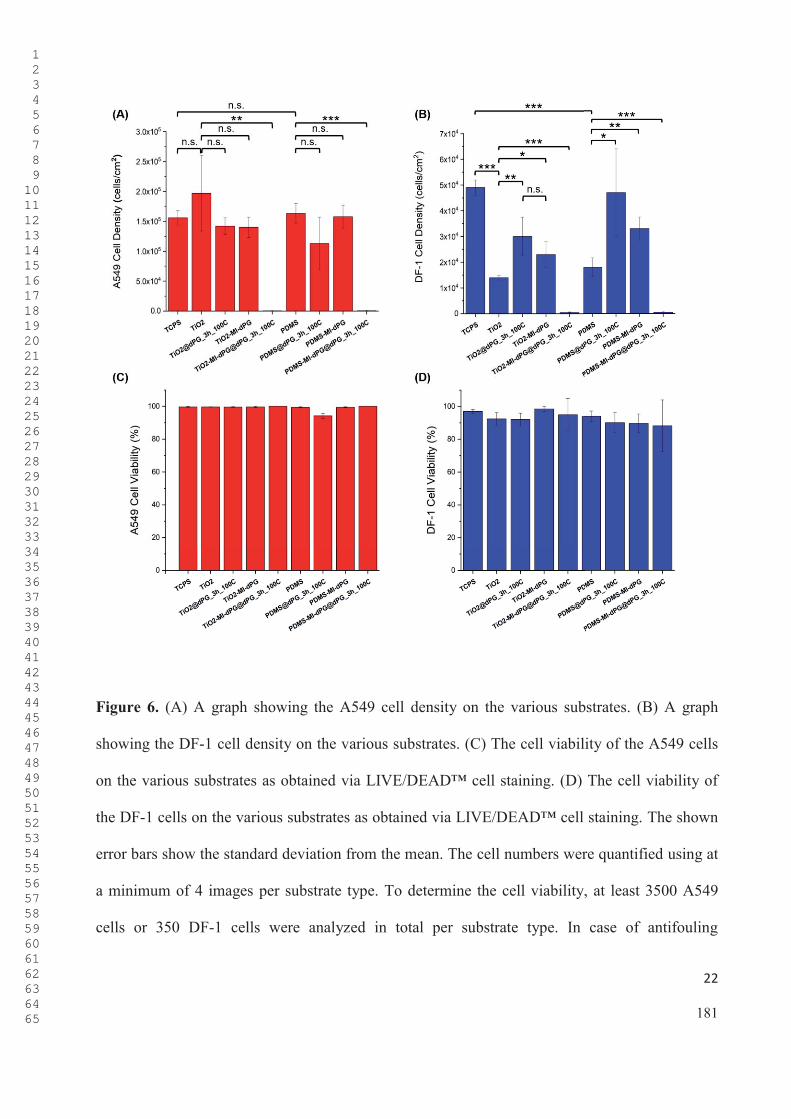
22
Figure 6. (A) A graph showing the A549 cell density on the various substrates. (B) A graph
showing the DF-1 cell density on the various substrates. (C) The cell viability of the A549 cells
on the various substrates as obtained via LIVE/DEAD™ cell staining. (D) The cell viability of
the DF-1 cells on the various substrates as obtained via LIVE/DEAD™ cell staining. The shown
error bars show the standard deviation from the mean. The cell numbers were quantified using at
a minimum of 4 images per substrate type. To determine the cell viability, at least 3500 A549
cells or 350 DF-1 cells were analyzed in total per substrate type. In case of antifouling
1 2 3 4 5 6 7 8 9 1011121314151617181920212223242526272829303132333435363738394041424344454647484950515253545556575859606162636465 181
23
TiO2–MI-dPG@dPG3 h, 100 °C and PDMS–MI-dPG@dPG3 h, 100 °C a minimum of 10 cells per cell
type was analyzed for quantification of the viability. * p = 0.05. ** p = 0.01. *** p = 0.001. The
p values were calculated utilizing a two-tailed T-test under the assumption of equal variance.
CONCLUSIONS
In the current work, a novel universal method for the grafting of dendritic polyglycerol (dPG)
from mussel-inspired adhesion layers was achieved. The successful grafting of dPG from
TiO2–MI-dPG and PDMS–MI-dPG was confirmed by means of CA measurements, XPS, and
SEM. Additionally, it was shown that the dPG grafting process occurred insufficiently in the
absence of the MI-dPG coating on both substrate types. When the proliferation and viability of
A549 and DF-1 cells on the various coatings was investigated, high numbers of viable cells were
observed on the tissue culture polystyrene control, on the bare TiO2, and on the PDMS substrate.
Introduction of the MI-dPG coating to the TiO2 and PDMS substrates did not influence the A549
cell numbers, whereas the DF-1 cell numbers slightly increased. Subsequent dPG grafting from
the MI-dPG coatings led to a dramatic decrease in the cell numbers of both cell types for both
substrate types. However, no decrease in the cell viability was observed at the surface (> 88%
viability in all cases). The reduced cell numbers were explained by the successful formation of a
surface hydration layer on the dPG-grafted coating, which prevented the adhesion and
proliferation of cells. The combined results showed that the grafting of dPG from MI-dPG-
coated substrates provides a successful strategy for the creation of cell-repelling but highly
biocompatible surfaces.
1 2 3 4 5 6 7 8 9 1011121314151617181920212223242526272829303132333435363738394041424344454647484950515253545556575859606162636465 182

24
The method developed in the current work gives exact control over the wettability of the
substrate (i.e., CA values from 60° till < 10° were easily achieved by adjusting the reaction time
and temperature) while maintaining the chemical characteristics of the surface (i.e., effectively a
dPG surface with tunable CA was developed). Resulting from the substrate-independent
adhesion character of the MI-dPG polymer,[19] the method presented in the current work could be
utilized to graft dPG from a broad spectrum of substrates, independent from the chemical or
physical characteristics of the substrate materials. Therefore, the direct grafting of antifouling
dPG as developed in earlier works,[27-28] can now be extended to a broad range of (medically
relevant) hydrophilic and hydrophobic substrates (e.g. prosthetic materials, cardiovascular
implant materials, and materials for implantable biosensors). Additionally, the dPG grafting
process was performed in bulk (i.e., solvent-free), in the absence of caustic bases, and without
activation of the substrate material prior to the grafting process, following a simple two-step
procedure (i.e., MI-dPG coating of the substrate and dPG grafting).
EXPERIMENTAL SECTION
All materials and (analytical) methods are described in Sections 1.1., 1.2., and 1.3. of the ESI.
1 2 3 4 5 6 7 8 9 1011121314151617181920212223242526272829303132333435363738394041424344454647484950515253545556575859606162636465 183

25
ASSOCIATED CONTENT
AUTHOR INFORMATION
Contact Corresponding Author:
E-Mail: [email protected] (M.W.K.), [email protected] (R.H.).
Author Contributions:
Michaël W. Kulka (main author): conceived the project and conducted all grafting experiments.
Furthermore, he performed and interpreted all CA and SEM measurements. Arushi Garg
performed a significant part of the grafting reactions under supervision of the main author during
an internship. Philip Nickl fitted and interpreted all XPS data. Furthermore, he proofread the
manuscript. Dirk Salz fabricated all titanium dioxide coated glass surfaces using special PVD
techniques. Ingo Grunwald (PI) facilitated the machinery required for the titanium dioxide
coating process and contributed to the interpretation of results that were discussed in the current
work. Jörg Radnik (PI) facilitated the machinery required for the XPS measurements, and
contributed to the discussion of the results of the current project. Rainer Haag (PI) facilitated the
required pre-knowledge, work space, analytical support, and financial support that were required
for this work.
1 2 3 4 5 6 7 8 9 1011121314151617181920212223242526272829303132333435363738394041424344454647484950515253545556575859606162636465 184
The ESI is available free of charge on the XXXXX website at DOI: XXXXX.

26
Funding Sources
This work was funded by the German Ministry of Science and Education (BMBF) via the KMU-
Innovativ program (under the project name "GlycoVAD").
ACKNOWLEDGEMENTS
First, we would like to thank the BMBF for the financial support of the "GlycoVAD" project via
the KMU-Innovativ program. Additionally, we would like to thank M. Eng. J. Stockmann
(Bundesanstalt für Materialforschung und -prüfung, Berlin, Germany) for performing the XPS
measurements. We would also like to acknowledge the assistance of the core facility
BioSupraMol (located at the Freie Universität Berlin and supported by the Deutsche
Forschungsgemeinschaft (DFG)) in the chemical characterizations methods that were performed
in this work. Finally, we would like to thank Dr. P. Winchester, and Dr. R. Randriantsilefisoa for
proofreading the manuscript, and E. Ziegler and Dr. W. Fischer for taking care of all legal
matters considering this work.
1 2 3 4 5 6 7 8 9 1011121314151617181920212223242526272829303132333435363738394041424344454647484950515253545556575859606162636465 185

27
LITERATURE
[1] a) R. M. Donlan, Clinical Infectious Diseases 2001, 33, 1387; b) D. Pavithra, M. Doble, Biomedical Materials 2008, 3, 034003; c) N. Cole, E. B. H. Hume, A. K. Vijay, P. Sankaridurg, N. Kumar, M. D. P. Willcox, Investigative Ophthalmology & Visual Science2010, 51, 390; d) Y. Ohko, Y. Utsumi, C. Niwa, T. Tatsuma, K. Kobayakawa, Y. Satoh, Y. Kubota, A. Fujishima, Journal of Biomedical Materials Research: An Official Journal of The Society for Biomaterials, The Japanese Society for Biomaterials, and The Australian Society for Biomaterials and the Korean Society for Biomaterials 2001, 58, 97; e) K. Vasilev, J. Cook, H. J. Griesser, Expert Review of Medical Devices 2009, 6, 553; f) M. D. P. Willcox, E. B. H. Hume, Y. Aliwarga, N. Kumar, N. Cole, Journal of Applied Microbiology 2008, 105, 1817; g) N. Wisniewski, M. Reichert, Colloids and Surfaces B: Biointerfaces 2000, 18, 197; h) C. Yang, G. L. Liang, K. M. Xu, P. Gao, B. Xu, Journal of Materials Science 2009, 44, 1894; i) K. T. Meilert, D. Laub, J. Kiwi, Journal of Molecular Catalysis A: Chemical 2005, 237, 101; j) J. Bozja, J. Sherrill, S. Michielsen, I. Stojiljkovic, Journal of Polymer Science Part A: Polymer Chemistry 2003, 41, 2297; k) B. Meyer, International Biodeterioration & Biodegradation 2003, 51, 249; l) X. Li, Y. Xing, Y. Jiang, Y. Ding, W. Li, International Journal of Food Science & Technology 2009, 44, 2161; m) A. CONTE, G. G. BUONOCORE, A. BEVILACQUA, M. SINIGAGLIA, M. A. D. NOBILE, Journal of Food Protection2006, 69, 866; n) E.-R. Kenawy, S. D. Worley, R. Broughton, Biomacromolecules 2007, 8, 1359; o) P. Asuri, S. S. Karajanagi, R. S. Kane, J. S. Dordick, Small 2007, 3, 50; p) D. M. Yebra, S. Kiil, K. Dam-Johansen, Progress in Organic Coatings 2004, 50, 75; q) L. D. Chambers, K. R. Stokes, F. C. Walsh, R. J. K. Wood, Surface and Coatings Technology 2006, 201, 3642; r) H.-C. Flemming, Applied Microbiology and Biotechnology 2002, 59, 629.
[2] a) R. O. Darouiche, New England Journal of Medicine 2004, 350, 1422; b) B. W. Trautner, R. O. Darouiche, Am J Infect Control
1 2 3 4 5 6 7 8 9 1011121314151617181920212223242526272829303132333435363738394041424344454647484950515253545556575859606162636465 186

28
2004, 32, 177; c) I. H. Jaffer, J. C. Fredenburgh, J. Hirsh, J. I. Weitz, Journal of Thrombosis and Haemostasis 2015, 13, S72.
[3] M. Hakim, I. Utama, B. Nugroho, A. Yusim, M. Baithal, I. Suastika, presented at Proceeding of SENTA: 17th Conference on Marine Technology 2017.
[4] I. B. Beech, J. Sunner, Current Opinion in Biotechnology 2004, 15, 181.
[5] S. Chen, L. Li, C. Zhao, J. Zheng, Polymer 2010, 51, 5283. [6] L. Q. Xu, D. Pranantyo, J. B. Liu, K.-G. Neoh, E.-T. Kang, Y. X.
Ng, S. L.-M. Teo, G. D. Fu, Rsc Advances 2014, 4, 32335. [7] P. Petrov, G. Georgiev, D. Momekova, G. Momekov, C. B.
Tsvetanov, Polymer 2010, 51, 2465. [8] J. Telegdi, T. Rigó, J. Beczner, E. Kálmán, Surface Engineering
2005, 21, 107. [9] a) P. Bertrand, A. Jonas, A. Laschewsky, R. Legras,
Macromolecular Rapid Communications 2000, 21, 319; b) C. Freij-Larsson, T. Nylander, P. Jannasch, B. Wesslén, Biomaterials1996, 17, 2199.
[10] a) C. D. Bain, E. B. Troughton, Y. T. Tao, J. Evall, G. M. Whitesides, R. G. Nuzzo, Journal of the American Chemical Society 1989, 111, 321; b) S. P. Pujari, L. Scheres, A. T. M. Marcelis, H. Zuilhof, Angewandte Chemie International Edition2014, 53, 6322.
[11] H. Lee, S. M. Dellatore, W. M. Miller, P. B. Messersmith, Science2007, 318, 426.
[12] J. H. Waite, The Journal of Experimental Biology 2017, 220, 517. [13] J. H. Waite, M. L. Tanzer, Science 1981, 212, 1038. [14] J. Saiz-Poseu, J. Mancebo-Aracil, F. Nador, F. Busqué, D. Ruiz-
Molina, Angewandte Chemie International Edition 2019, 58, 696. [15] H. Lee, N. F. Scherer, P. B. Messersmith, Proc Natl Acad Sci U S
A 2006, 103, 12999. [16] S. M. D. Haeshin Lee, William M. Miller, Phillip B. Messersmith,
Science 2007, 318, 426.
1 2 3 4 5 6 7 8 9 1011121314151617181920212223242526272829303132333435363738394041424344454647484950515253545556575859606162636465 187

29
[17] a) R. Batul, T. Tamanna, A. Khaliq, A. Yu, Biomaterials science2017, 5, 1204; b) T. G. Kim, H. Lee, Y. Jang, T. G. Park, Biomacromolecules 2009, 10, 1532.
[18] Q. Wei, F. Zhang, J. Li, B. Li, C. Zhao, Polymer Chemistry 2010,1, 1430.
[19] Q. Wei, K. Achazi, H. Liebe, A. Schulz, P.-L. M. Noeske, I. Grunwald, R. Haag, Angewandte Chemie International Edition2014, 53, 11650.
[20] a) M. W. Kulka, I. S. Donskyi, N. Wurzler, D. Salz, Ö. Özcan, W. E. S. Unger, R. Haag, ACS Applied Bio Materials 2019, 2, 5749; b) M. Li, C. Schlaich, M. W. Kulka, I. S. Donskyi, T. Schwerdtle, W. E. Unger, R. Haag, Journal of Materials Chemistry B 2019.
[21] C. Schlaich, L. Yu, L. C. Camacho, Q. Wei, R. Haag, PolymerChemistry 2016, 7, 7446.
[22] a) K. Prime, G. Whitesides, Science 1991, 252, 1164; b) J. H. Lee, J. Kopecek, J. D. Andrade, Journal of Biomedical Materials Research 1989, 23, 351.
[23] S. Han, C. Kim, D. Kwon, Polymer 1997, 38, 317. [24] A. Judge, K. McClintock, J. R. Phelps, I. MacLachlan, Molecular
Therapy 2006, 13, 328. [25] C. Siegers, M. Biesalski, R. Haag, Chemistry – A European
Journal 2004, 10, 2831.[26] a) Q. Wei, S. Krysiak, K. Achazi, T. Becherer, P.-L. M. Noeske, F.
Paulus, H. Liebe, I. Grunwald, J. Dernedde, A. Hartwig, T. Hugel, R. Haag, Colloids and Surfaces B: Biointerfaces 2014, 122, 684; b) T. B. Qiang Wei, Radu-Cristian Mutihac, Paul-Ludwig Michael Noeske, Florian Paulus, Rainer Haag, and Ingo Grunwald, Biomacromolecules 2014, 15, 3061.
[27] a) E. Moore, B. Delalat, R. Vasani, G. McPhee, H. Thissen, N. H. Voelcker, ACS Applied Materials & Interfaces 2014, 6, 15243; b) M. Khan, W. T. S. Huck, Macromolecules 2003, 36, 5088.
[28] T. Weber, M. Bechthold, T. Winkler, J. Dauselt, A. Terfort, Colloids and Surfaces B: Biointerfaces 2013, 111, 360.
[29] A. Sunder, R. Hanselmann, H. Frey, R. Mülhaupt, Macromolecules1999, 32, 4240.
1 2 3 4 5 6 7 8 9 1011121314151617181920212223242526272829303132333435363738394041424344454647484950515253545556575859606162636465 188
30
[30] P. Louette, F. Bodino, J.-J. Pireaux, Surface Science Spectra 2005,12, 38.
[31] C. Schlaich, L. Cuellar Camacho, L. Yu, K. Achazi, Q. Wei, R. Haag, ACS Applied Materials & Interfaces 2016, 8, 29117.
1 2 3 4 5 6 7 8 9 1011121314151617181920212223242526272829303132333435363738394041424344454647484950515253545556575859606162636465 189

Supporting Information for
Surface-Initiated Grafting of Dendritic Polyglycerol from Mussel-Inspired Adhesion
Layers for the Creation of Biocompatible Cell-Repelling Coatings
Michaël W. Kulka,a Chuanxiong Nie,a Philip Nickl,a,b Yannic Kerkhoff,a Arushi Garg,a Dirk
Salz,c Jörg Radnik,b Ingo Grunwald,c,d Rainer Haag*,a
a Institute for Chemistry and Biochemistry, Freie Universität Berlin, Takustraße 3, 14195 Berlin,
Germany
b BAM – Federal Institute for Material Research and Testing, Division of Surface Analysis and
Interfacial Chemistry, Unter den Eichen 44-46, 12205 Berlin, Germany
c Fraunhofer Institute for Manufacturing Technology and Advanced Materials IFAM, Wiener
Straße12, 28359 Bremen, Germany
d Hochschule Bremen – City University of Applied Sciences, Department of Industrial and
Environmental Biology, Neustadtswall 30, 28199 Bremen, Germany
190

1. EXPERIMENTAL SECTION
1.1. CHEMICALS & LAB TECHNIQUES
The chemicals were purchased from Merck (Darmstadt, Germany) and were used as received
without further purification, unless mentioned otherwise. Besides, NaOH pellets bought from
VWR International (Darmstadt, Germany). Non-protic solvents were either purchased in an
extra-dry form or were dried with the help of CaH2, prior to use. Dialysis was performed using
benzoylated cellulose tubes (D7884, width: 32 mm; molecular-weight cutoff (MWCO): 2 kDa)
purchased from Merck (Darmstadt, Germany). Deionized water was purified using a water
purification system by Millipore (Burlington, Massachusetts, USA), with a minimum resistivity
cm. All grafting reactions were performed under dry and inert conditions (argon
atmosphere), using Schlenk technique and custom-made glassware (Figure S1).
Figure S1. (A) Custom-made glassware for the incubation of the substrates with glycidol. The
glassware was fabricated in such a manner that it could withstand the high vacuum (1 x 10⁻³ bar)
191

conditions that were required for the drying process of the flask. The cooler was necessary
because glycidol tends to evaporate at elevated temperatures (> 100 °C). The glass flask
contained a glass rack at the bottom, which was used for the placement of the substrate holders.
(B) A picture of one of the custom-made Teflon substrate holders that were used to place the
(MI-dPG-coated) substrates into the reaction flask.
1.1.1. Static Water Contact Angle Measurements
Static water contact angle (CA) measurements were performed by applying a Dataphysics
Instruments GmbH (Filderstadt, Germany) OCA 20 contact-angle measure device, according to
the sessile drop method. The OCA 20 system was equipped with a six-fold zoom lens with
integrated fine focus (+/- 6 mm) and a high light-transmitting-capacity CCD-camera, with a
resolution of max 768 x 576 pixels. The used video system was a high performance imaging
processing system, with a 132 Mbytes/s data transfer rate, and a digitizing speed up to 50
images/s. Image processing was performed by applying SCA 202 software also by Dataphysics
Instruments GmbH.
1.1.2. Scanning Electron Microscopy
The surface morphology was investigated using a field emission scanning electron microscope
(FE-SEM) model SU8030 by Hitachi (Chiyoda, Japan), at an accelerating voltage (Vac) of 20 kV,
a current of 15 μA, and a working distance of 8.5 inches. The substrates were sputtered with a 5
192

nm conductive gold layer prior to the SEM measurements, using a CCU-010 sputter machine by
Safematic GmbH (Bad Ragaz, Switzerland).
1.1.3. X-Ray Photoelectron Spectroscopy
X-ray photoelectron spectroscopy (XPS) spectra were recorded on a Kratos (Manchester, UK)
-ray source. The spectra
were measured in normal emission, and a source-to-sample angle 60° was used. All spectra were
recorded utilizing the fixed analyzer transmission (FAT) mode. The binding energy scale of the
instrument was calibrated, following a technical procedure provided by Kratos Analytical Ltd
(calibration was performed according to ISO 15472). The spectra were recorded utilizing the
instrument’s slot and hybrid lens modes. An analysis area of approximately a 300 μm x 700 μm
was investigated; charge neutralization was applied. For quantification, the survey spectra were
measured with a pass energy of 80 electron volt (eV), and the spectra were quantified utilizing
the empirical sensitivity factors that were provided by KRATOS (the sensitivity factors were
corrected with the transmission function of the spectrometer).
The high-resolution XPS spectra were measured with a pass energy of 20 eV, and the
respective data were processed using UNIFIT spectrum processing software.[1] For fitting, a
Shirley background and a Gaussian/Lorentzian sum function (peak shape model GL (30)) were
used. If not denoted otherwise, the L-G mixing component was set to 0.35 for all peaks. In case
of the C1s spectra, peak fitting was performed in such a manner that all residual structures were
193

removed, and all binding energies were calibrated to the signal observed for the aliphatic C–C
bond component (observed at 248.8 eV).
1.1.4. MI-dPG Synthesis
Dendritic polyglycerol (dPG) with Mn: 12,000 and Mw: 16,000 was polymerized in a one-step
ring-opening anionic polymerization, as described in earlier work by Sunder et al.[2] The amine-
functionalized dPG (dPG–NH2) was produced by mesylation, azidation, and subsequent
Staudinger reduction of the introduced azides, according to procedures that were earlier
published by our group.[3] The dPG–NH2 (4 g, 0.38 mmol) was dissolved in MeOH (100 ml), and
10% HCl-solution was added until a neutral pH was obtained. Subsequently, an aqueous buffer
solution of 2–(N–morpholino) ethane sulfonic acid (MES) (0.1 M, pH: 4.8) was added, so that a
1:1 (V:V) ratio of MeOH to buffer was obtained. Next, 3,4–dihydroxy–hydrocinnamic acid
(DHHA) (20 g, 110 mmol, 2 equivalent respectively to 100% of the –NH2 groups), 1–ethyl–3–
(3–dimethylamino)propyl)carboiimide (21 g, 110 mmol, 2.0 equivalent respective to 100% of the
–NH2 groups) were added, and the resulting reaction mixture was stirred for 16 h at room
temperature. The reaction mixture was then purified by dialysis in MeOH. In order to increase
product stability (i.e., to prevent polymerization), 37% HCl-solution was added to the dialysis-
solution (1 drop per gram of product). The pure product was obtained upon removal of the
solvent by means of rotary evaporation. The product was stored under argon atmosphere at
-20 °C.
194
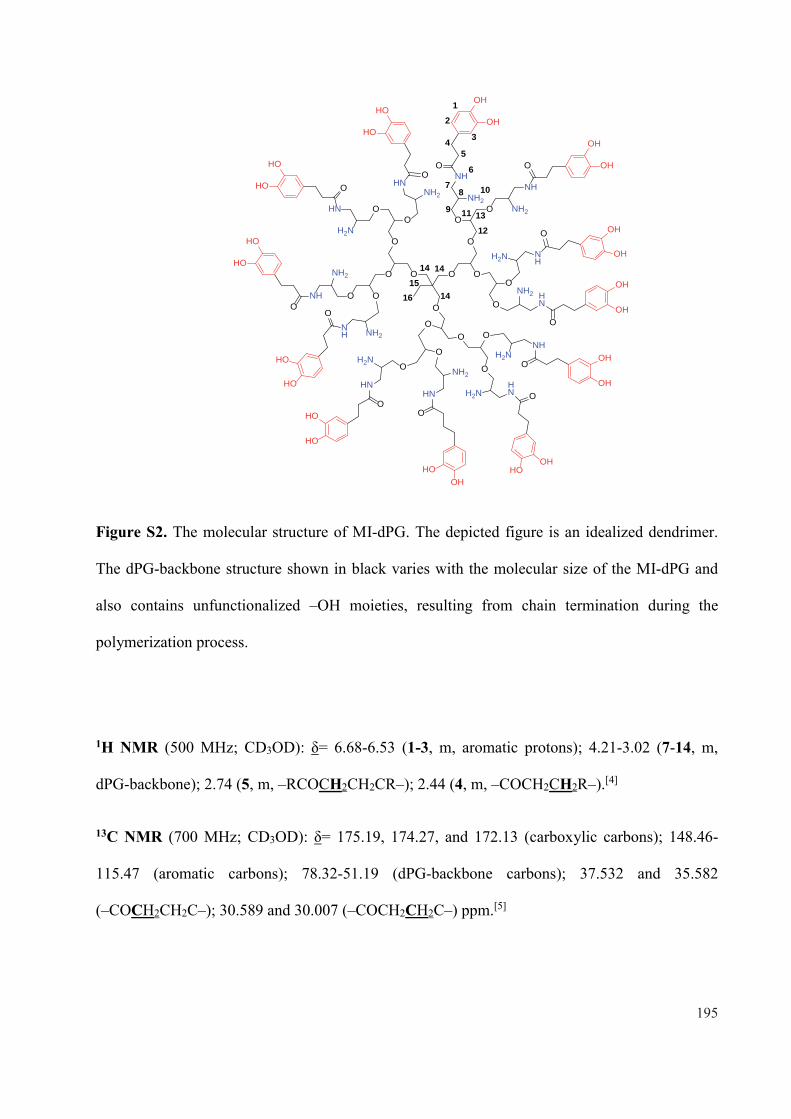
OO
O
O
O
OO
O
O
OO
OO
O
OOO
O
O
O
O
H2N
NH2
NHNH2
NH
NH2
HN
H2N
HN
NH2
NH
NH2NH
H2N
HNNH2
HN H2NHN
H2NNH
NH2 HNO
O
HO
HO
O
HO
HO
HO
HOO
HO
HO
O
HOOH
O
OH
OH
NH
O
OH
OHO
OH
OH
O
OHHO
O
OH
OH
O
OH
OH
O
HO
HO
12
345
6
78
9
10
11
1213
14
14
1415
16
Figure S2. The molecular structure of MI-dPG. The depicted figure is an idealized dendrimer.
The dPG-backbone structure shown in black varies with the molecular size of the MI-dPG and
also contains unfunctionalized –OH moieties, resulting from chain termination during the
polymerization process.
1H NMR (500 MHz; CD3OD): = 6.68-6.53 (1-3, m, aromatic protons); 4.21-3.02 (7-14, m,
dPG-backbone); 2.74 (5, m, –RCOCH2CH2CR–); 2.44 (4, m, –COCH2CH2R–).[4]
13C NMR (700 MHz; CD3OD): = 175.19, 174.27, and 172.13 (carboxylic carbons); 148.46-
115.47 (aromatic carbons); 78.32-51.19 (dPG-backbone carbons); 37.532 and 35.582
(–COCH2CH2C–); 30.589 and 30.007 (–COCH2CH2C–) ppm.[5]
195

1.2. SURFACE CHEMISTRY
1.2.1. Coating glass with TiO2 via Physical Vapor Deposition
Glass microscope slides (76 mm x 26 mm, thickness 1 mm) purchased from VWR International
(Radnor, Pennsylvania, USA) were coated with a transparent titanium dioxide (TiO2) layer (ca.
30 nm) by means of physical vapor deposition (PVD). The TiO2 coatings were prepared using
radio frequency (13.56 MHz) reactive sputtering. Oxygen 5.0 and argon 4.6 purchased from
Linde plc (Munich, Germany), and a titanium target (99.9 % purity) purchased from Sindlhauser
Materials GmbH (Kempten, Germany) were used as source materials. The sputtering chamber
(50 cm x 50 cm x 50 cm) was evacuated to a base pressure of 1 x 10⁻⁵ mbar. Subsequently, the
substrates were plasma cleaned with oxygen (60 standard cubic centimeter per minute (sccm))
and argon (60 sccm) for 5 min (sputtering power: 2380 W). Without venting the chamber, the
target was sputtered using an Ar-flux (120 sscm, sputter power: 2380 W). After the sputter
plasma showed a blue color, an additional 9 sccm of oxygen was added to the chamber. The blue
color indicated metallic titanium on the surface of the target, i.e., the absence of a TiO2-layer.
After a reactive sputtering time of 10 min, a 25 nm thick TiO2-coating was obtained on the
substrates. To get fully oxidized TiO2, the distance between target and substrate was maximized
(58 cm).
196

1.2.2. PDMS Spin Coating
Glass microscope slides (76 mm x 26 mm, thickness 1 mm) purchased from VWR International
(Radnor, Pennsylvania, USA) were spin coated with a solution of PDSM in xylol (1 wt%). The
glass slides (cut in ca. 1 x 1 cm) were spin coated at 3,000 rpm for 1 min. Spin coating was
performed using a WS-650Mz-23NPPB spin coater by Laurell Technologies corporation (North
Wales, Pennsylvania, USA).
1.2.3. MI-dPG Coating
TiO2-coated glass substrates were cleaned by ultrasonic treatment in EtOH for 10 min, prior the
coating procedure. The cleaned surfaces were then immerged in a solution of MI-dPG
(4 mg, 1.33 x 10⁻⁴ mmol) in MeOH (2 ml) to which an aqueous solution of 3–
(N–morpholino)propane sulfonic acid (MOPS) buffer (2 ml, 0.1 M, pH: 8.5) was added,
initiating the polymerization reaction of MI-dPG. The surfaces were immersed in the
polymerizing solution for 10 min (immersion depth ca 1 cm), after which they were removed
from the solution and thoroughly rinsed with EtOH. Subsequently, the substrates were dried
under a N2-flow and placed in a custom glass flask (Figure S1) at 110 °C under high vacuum
conditions (1 x 10⁻³ bar) for > 10 h. The PDMS-spin-coated substrates were functionalized with
MI-dPG according to the same procedure.
197

1.2.4. dPG Grafting
Prior to the grafting reaction, glycidol was dried overnight in a pre-dried Schlenk-flask
containing molecular sieve (type 562 C, pore size 3 Å) by Carl Roth GmbH (Karlsruhe,
Germany). Additionally, the (MI-dPG-coated) substrates were dried overnight at 110 °C under
high vacuum conditions (1 x 10⁻³ bar) using custom glassware (Figure S1). The flask was
removed from the oil bath and was cooled down to room temperature. The flask was then flushed
with argon, and subsequently glycidol was added to the flask under argon backflow. Next, the
flask was placed back in the oil bath at 80 °C, 100 °C, or 120 °C for 30 min, 1 h, 3 h, or 24 h,
allowing the grafting of dendritic polyglycerol (dPG) from the surface. After the grafting
reaction, the substrates were removed from the system, thoroughly rinsed with EtOH (3x), and
subsequently placed in a beaker glass containing in EtOH for > 10 h. Next, the substrates were
dried under N2 flow and dried at 50 °C for 1 h prior to any further measurements.
1.3. BIOLOGICAL ASSAYS
1.3.1. LIVE/DEAD Staining of A549 and DF-1 Cells
Human adenocarcinoma cells (A549 cells) and chicken fibroblast cells (DF-1 cells) were
maintained as a monolayer culture in tissue culture polystyrene (TCPS) petri dishes containing
Dulbecco’s Modified Eagle’s Medium (DMEM) supplemented with fetal bovine serum (FBS)
(10 v%), streptomycin (100 mg/ml), and penicillin (100 units/ml). The cell lines were cultured
under 5% CO2 at 37 °C, using a laboratory CO2 incubator by Heraeus Holding GmbH (Hanau,
Germany). MI-dPG coated substrates were prepared according to the procedure described in
198

Section 1.2.3. of this document. Subsequently, the samples were sterilized with EtOH (75 vol%
in Milli-Q) for 10 min and washed with cell culture medium before the seeding. The cells were
seeded at a concentration of 1 x 10⁶ cells/mL. After 24 h of culturing, the cells were stained
utilizing a commercially available LIVE/DEAD™ Viability/Cytotoxicity Kit (Order No: L3224)
by Thermo Fisher Scientific Inc. (Waltham, Massachusetts, USA) and visualized using
AxioObserver Z.1 microscope by the Carl Zeiss AG (Oberkochen, Germany). Zen blue software
(also provided by the Carl Zeiss AG) was applied for image capturing.
1.3.2. Automated LIVE/DEAD™ Quantification
Automatic image analysis was performed with the Java-based image processing program
"ImageJ" developed by the Laboratory for Optical and Computational Instrumentation of the
University of Wisconsin (Madison, Wisconsin, USA).[6] Cell recognition was achieved via
distinctive assessment of fluorescence signals from live and dead cells. First, the cells were
separated from the background utilizing the "subtract background" function of "ImageJ". In this
process, a rolling ball radius of 50 pixels was chosen. The cells were separated from the
background by thresholding the fluorescence value of the 16-bit images (threshold Live: 1510,
threshold Dead: 150). After binarization, cell clusters were segmented utilizing a "watershed
algorithm" for the separation of different objects in an image (coefficient: 0.1). Subsequently, the
particle analyzer function of ImageJ was utilized for cell quantification and morphology analysis.
To avoid counting single pixels or cell fragments, only objects above a specific size were
analyzed (i.e., only objects bigger than 10 pixels were analyzed). Finally, the results were
199
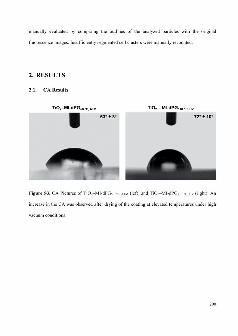
manually evaluated by comparing the outlines of the analyzed particles with the original
fluorescence images. Insufficiently segmented cell clusters were manually recounted.
2. RESULTS
2.1. CA Results
Figure S3. CA Pictures of TiO2–MI-dPG50 °C, ATM (left) and TiO2–MI-dPG110 °C, HV (right). An
increase in the CA was observed after drying of the coating at elevated temperatures under high
vacuum conditions.
200

Table S1. CA values for TiO2–MI-dPG50 °C, ATM and TiO2–MI-dPG110 °C, HV.
SA TiO2–MI-dPG50 °C, ATM Mean (μ) STDVB
I 65.8° 64.1° 64.5°
62.6° 2.9°II 59.6° 63.2° 64.6°
III 56.1° 61.4° 64.0°
TiO2–MI-dPG110 °C, HV
I 60.1° 52.1° 62.6°
71.9° 10.0°II 79.6° 77.6° 79.8°
III 79.1° 78.3° 78.2°
Note for A, S = Substrate. Note for B, STDV = Standard deviation from the mean.
201

Figure S4. The images and the average CA values obtained for TiO2@dPG and
TiO2–MI-dPG@dPG at various dPG grafting times and temperatures.
Table S2. CA values for TiO2 and TiO2–MI-dPG after dPG grafting at various times and
temperatures.
SA Bare TiO2 Mean (μ) STDVB
I 72.4° 69.0° 79.5°
71.9° 6.1°II 80.1° 73.5° 78.3°
III 67.5° 63.9° 63.0°
202

TiO2@dPG30 min, 100 °C
I 60.2° 65.2° 62.6°
62.3° 7.3°II 66.9° 64.7° 64.2°
III 42.6° 68.0° 66.2°
TiO2@dPG1 h, 100 °C
I 61.2° 58.0 ° 55.7°
57.7° 2.5°II 55.3° 56.3° 59.0°
III 53.6° 58.4° 61.4°
TiO2@dPG3 h, 100 °C
I 53.5° 54.2° 52.4°
51.4° 3.9°II 54.2° 41.2° 51.2°
III 54.2° 51.6° 50.0°
TiO2@dPG24 h, 100 °C
I 17.0° 12.2° 11.5°
15.1° 2.5°II 16.6° 15.1° 16.7°
III 11.4° 17.3° 18.2°
203

TiO2–MI-dPG
I 60.1° 52.1° 62.6°
71.9° 10.0°II 79.6° 77.6° 79.8°
III 79.1° 78.3° 78.2°
TiO2–MI-dPG@dPG30 min, 80 °C
I 63.2° 47.0° 62.2°
61.3° 5.6°II 63.7° 62.1° 58.4°
III 63.3° 67.9° 64.0°
TiO2–MI-dPG@dPG1 h, 80 °C
I 72.0° 69.1° 70.8°
64.0° 6.2°II 54.4° 55.8° 57.3°
III 66.4° 63.9° 66.3°
TiO2–MI-dPG@dPG3 h, 80 °C
I 50.7° 46.9° 49.6°
47.8° 1.9°II 47.6° 44.8° 44.8°
III 48.1° 49.1° 48.6°
204

TiO2–MI-dPG@dPG24 h, 80 °C
I 9.3° 5.9° < 10°
< 10° N.A.II 3.1° < 10° < 10°
III 4.5° 8.8° < 10°
TiO2–MI-dPG@dPG30 min, 100 °C
I 57.8° 54.8° 47.4°
50.1° 4.0°II 48.9° 46.5° 53.7°
III 48.0° 46.2° 47.4°
TiO2–MI-dPG@dPG1 h, 100 °C
I 44.2° 44.4° 42.5°
40.1° 5.6°II 39.1° 47.5° 33.3°
III 42.3° 39.1° 28.8°
TiO2–MI-dPG@dPG3 h, 100 °C
I < 10° < 10° 10.7°
< 10° N.A.II < 10° < 10° < 10°
III < 10° < 10° < 10°
205

TiO2–MI-dPG@dPG24 h, 100 °C
I 12.1° 12.5° 13.3°
12.5° 1.5°II < 10° 13.8° 11.6°
III 13.4° 14.7° 11.9°
TiO2–MI-dPG@dPG30 min, 120 °C
I 32.8° 40.3° 34.6°
35.0° 4.5°II 28.7° 26.6° 39.4°
III 36.3° 36.9° 38.9°
TiO2–MI-dPG@dPG1 h, 120 °C
I 33.5° 14.9° 27.3°
25.4° 6.5°II 31.7° 21.6° 33.6°
III 19.3° 27.4° 19.0°
TiO2–MI-dPG@dPG3 h, 120 °C
I 30.7° 20.1° 14.6°
23.1° 7.2°II 22.4° 13.7° 15.3°
III 26.9° 29.9° 34.1°
206

TiO2–MI-dPG@dPG24 h, 120 °C
I 24.2° 11.8° 13.7°
24.1° 9.2°II 37.8° 24.3° 15.9°
III 22.5° 27.5° 39.6°
Bare PDMS
I 111.5° 112.3° 110.8°
108.1° 3.8°II 102.6° 113.9° 106.4°
III 106.0° 103.7° 105.8°
Note for A, S = Substrate. Note for B, STDV = Standard deviation from the mean.
207

2.2. XPS Results
Table S3. Highly resolved C1s spectra for TiO2, TiO2–MI-dPG50 °C, ATM,
TiO2–MI-dPG110 °C, HV as determined by XPS.
Substrate Spectrum Binding energy
L-GMixing FWHM Chemical
stateRel.Area
TiO2
C 1s 284.8 0.35 1.4 C–C 0.78
286.1 0.35 1.0 C–O 0.15
288.2 0.35 1.0 C=O 0.07
TiO2 –
MI-dPG50 °C, ATM
C1s 284.8 0.35 1.2 C–C 0.40
286.3 0.35 1.1 C–O 0.54
288.1 0.35 1.1 C=O 0.06
TiO2 –
MI-dPG110 °C, HV
C1s 284.8 0.35 1.2 C–C 0.44
286.2 0.35 1.1 C–O 0.48
288.1 0.35 1.1 C=O 0.08
289.2 0.35 1.1 O–C=O 0.00
Fitting parameters and the relative areas for C1s component peaks at various binding energies in
XPS. The values reported for the C–O component include the C–N component resulting from
peak overlap.
208

Table S4. The C–O/C–C component peak area ratios for TiO2, TiO2–MI-dPG50 °C, ATM, and
TiO2–MI-dPG110 °C, HV as determined by XPS.
Substrate C–O/C–C
TiO2 0.19
TiO2–MI-dPG50 °C, ATM 1.35
TiO2 –MI-dPG110 °C, HV 1.09
The C–O/C–C component peak area ratios were calculated by dividing the relative area of the
peak fitted at ~286.5 eV (for the C–O component) by the relative area for the peak fitted at
~285.0 eV (for the C–C and C=C components). The values reported for the C–O component
include the C–N component resulting from peak overlap.
209

Table S5. Atomic C-, O-, N- and Ti-fractions of TiO2, TiO2–MI-dPG50 °C, ATM and
TiO2–MI-dPG110 °C, HV as determined by XPS.
Substrate C(at.%)A O (at.%)A N (at.%)A Ti (at.%)A
TiO2 22.3 52.3 0.6 12.9
TiO2–MI-dPG50 °C, ATM 67.4 23.3 7.3 0.6
TiO2–MI-dPG110 °C, HV 66.6 24.2 5.8 0.8
The elemental contents were extracted from the respective survey spectra (Figure S9 of the
appendix). Note for A, at.% = atomic percentage.
Table S6. Highly resolved C1s spectra for TiO2 and TiO2–MI-dPG after dPG grafting at varying
reaction times and temperatures as determined by XPS.
Substrate Spectrum Binding energy
L-GMixing FWHM Chemical
stateRel.Area
TiO2
C 1s 284.8 0.35 1.4 C–C 0.78
286.1 0.35 1.0 C–O 0.15
288.2 0.35 1.0 C=O 0.07
210

TiO2
@dPG30 min, 100 °C
C1s 284.8 0.35 1.2 C–C 0.41
286.2 0.35 1.2 C–O 0.50
288.1 0.35 1.1 C=O 0.05
289.0 0.35 1.1 O–C=O 0.04
TiO2
@dPG1 h, 100 °C
C1s 284.8 0.35 1.2 C–C 0.36
286.2 0.35 1.2 C–O 0.58
288.1 0.35 1.1 C=O 0.04
289.0 0.35 1.1 O–C=O 0.02
TiO2
@dPG3 h, 100 °C
C1s 284.8 0.35 1.1 C–C 0.31
286.0 0.35 1.3 C–O 0.60
287.8 0.35 1.1 C=O 0.03
288.8 0.35 1.1 O–C=O 0.06
TiO2
@dPG24 h, 100 °C
C1s 284.8 0.35 1.0 C–C 0.17
286.3 0.35 1.1 C–O 0.77
287.8 0.35 1.1 C=O 0.04
289.1 0.35 1.1 O–C=O 0.02
211

TiO2 –
MI-dPG
@dPG30 min, 80 °C
C1s 284.8 0.35 1.2 C–C 0.34
286.2 0.35 1.1 C–O 0.58
288.0 0.35 1.1 C=O 0.08
289.1 0.35 1.1 O–C=O 0.01
TiO2 –
MI-dPG
@dPG1 h, 80 °C
C1s 284.8 0.35 1.3 C–C 0.34
286.2 0.35 1.1 C–O 0.56
288.0 0.35 1.1 C=O 0.04
283.6 0.35 1.1 ChargeA 0.06
TiO2 –
MI-dPG
@dPG3 h, 80 °C
C1s 284.8 0.35 1.2 C–C 0.28
286.2 0.35 1.2 C–O 0.68
288.1 0.35 1.2 C=O 0.03
283.9 0.35 1.2 ChargeA 0.06
TiO2 –
MI-dPG
@dPG24 h, 80 °C
C1s 284.8 0.35 1.0 C–C 0.29
286.3 0.35 1.1 C–O 0.67
287.8 0.35 1.1 C=O 0.03
289.0 0.35 1.1 O–C=O 0.01
212

TiO2 –
MI-dPG
@dPG30 min, 100 °C
C1s 284.8 0.35 1.0 C–C 0.24
286.3 0.35 1.1 C–O 0.70
287.9 0.35 1.1 C=O 0.05
289.0 0.35 1.1 O–C=O 0.01
TiO2 –
MI-dPG
@dPG1 h, 100 °C
C1s 284.8 0.35 1.0 C–C 0.18
286.3 0.35 1.1 C–O 0.77
287.9 0.35 1.1 C=O 0.04
289.1 0.35 1.1 O–C=O 0.01
TiO2 –
MI-dPG
@dPG3 h, 100 °C
C1s 284.8 0.35 1.0 C–C 0.16
286.3 0.35 1.1 C–O 0.80
287.9 0.35 1.1 C=O 0.04
289.0 0.35 1.1 O–C=O 0.01
TiO2 –
MI-dPG
@dPG24 h, 100 °C
C1s 284.8 0.35 1.0 C–C 0.09
286.4 0.35 1.1 C–O 0.86
287.8 0.35 1.1 C=O 0.04
289.1 0.35 1.1 O–C=O 0.01
213
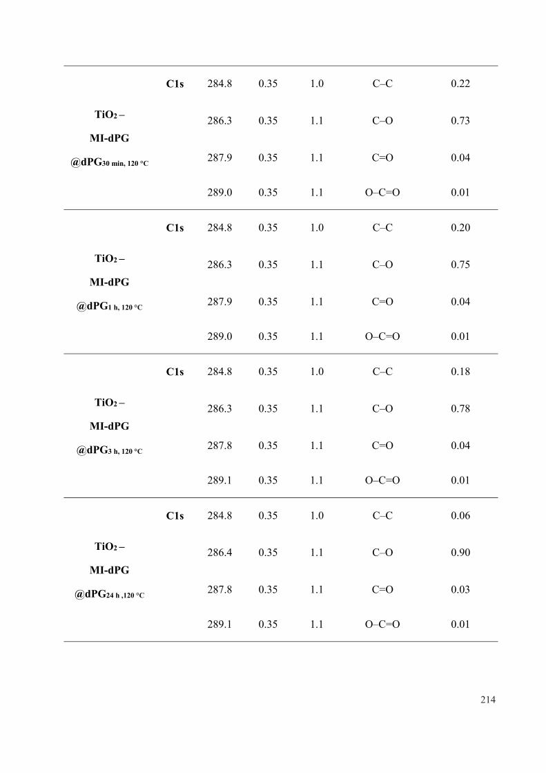
TiO2 –
MI-dPG
@dPG30 min, 120 °C
C1s 284.8 0.35 1.0 C–C 0.22
286.3 0.35 1.1 C–O 0.73
287.9 0.35 1.1 C=O 0.04
289.0 0.35 1.1 O–C=O 0.01
TiO2 –
MI-dPG
@dPG1 h, 120 °C
C1s 284.8 0.35 1.0 C–C 0.20
286.3 0.35 1.1 C–O 0.75
287.9 0.35 1.1 C=O 0.04
289.0 0.35 1.1 O–C=O 0.01
TiO2 –
MI-dPG
@dPG3 h, 120 °C
C1s 284.8 0.35 1.0 C–C 0.18
286.3 0.35 1.1 C–O 0.78
287.8 0.35 1.1 C=O 0.04
289.1 0.35 1.1 O–C=O 0.01
TiO2 –
MI-dPG
@dPG24 h ,120 °C
C1s 284.8 0.35 1.0 C–C 0.06
286.4 0.35 1.1 C–O 0.90
287.8 0.35 1.1 C=O 0.03
289.1 0.35 1.1 O–C=O 0.01
214

Fitting parameters and the relative areas for C1s component peaks at various binding energies in
XPS. The values reported for the C–O component include the C–N component resulting from
peak overlap. Note for A, during XPS-measurements the substrates might electrostatically
charge, due to the removal of electrons in proximity of the atomic nuclei. This charge is
automatically corrected via charge correction procedures, but might still lead to observable peaks
in the highly resolved C1s spectra.
Table S7. The C–O/C–C component peak area ratios for TiO2, TiO2–MI-dPG with dPG grafting
at varying reaction times and temperatures as determined by XPS
Substrate C–O/C–C
TiO2 0.19
TiO2@dPG30 min, 100 °C 1.22
TiO2@dPG1 h, 100 °C 1.61
TiO2@dPG3 h, 100 °C 1.94
TiO2@dPG24 h, 100 °C 4.53
TiO2–MI-dPG@dPG30 min, 80 °C 1.71
TiO2–MI-dPG@dPG1 h, 80 °C 1.65
TiO2–MI-dPG@dPG3 h, 80 °C 2.43
215

TiO2–MI-dPG@dPG24 h, 80 °C 2.31
TiO2–MI-dPG@dPG30 min, 100 °C 2.92
TiO2–MI-dPG@dPG1 h, 100 °C 4.28
TiO2–MI-dPG@dPG3 h, 100 °C 5.00
TiO2–MI-dPG@dPG24 h, 100 °C 9.56
TiO2–MI-dPG@dPG30 min, 120 °C 3.32
TiO2–MI-dPG@dPG1 h, 120 °C 3.75
TiO2–MI-dPG@dPG3 h, 120 °C 4.33
TiO2–MI-dPG@dPG24 h, 120 °C 15.00
The obtained ratios were calculated by dividing the relative area of the peak fitted at ~286.5 eV
(for C–O component) by the relative area for the peak fitted at ~285.0 eV (C–C and C=C
components). The values reported for the C–O component include the C–N component, resulting
from peak overlap.
216

Table S8. The atomic C-, O-, N-, and Ti-fractions for TiO2, TiO2–MI-dPG after dPG grafting at
varying reaction times and temperatures as determined by XPS.
Substrate C(at.%) O (at.%) N (at.%) Ti (at.%)
TiO2 22.3 52.3 0.6 12.9
TiO2@dPG30 min, 100 °C 30.5 51.6 0.3 16.3
TiO2@dPG1 h, 100 °C 29.3 52.6 0.2 15.6
TiO2@dPG3 h, 100 °C 36.8 49.3 0.4 12.4
TiO2@dPG24 h, 100 °C 59.8 37.7 0 1.8
TiO2–MI-dPG 66.6 24.2 5.8 0.8
TiO2 –
MI-dPG@dPG30 min, 80 °C
66.7 27.2 5.0 0.4
TiO2 –
MI-dPG@dPG1 h, 80 °C
68.2 27.3 3.6 0.2
TiO2 –
MI-dPG@dPG3 h, 80 °C
64.9 32.2 2.2 0.5
TiO2 –
MI-dPG@dPG24 h, 80 °C
70.2 29.2 0.5 0.0
217

TiO2 –
MI-dPG@dPG30 min, 100 °C
66.1 30.6 2.9 0.0
TiO2 –
MI-dPG@dPG1 h, 100 °C
64.9 33.3 1.5 0.1
TiO2 –
MI-dPG@dPG3 h, 100 °C
65.3 33.8 0.8 0.0
TiO2 –
MI-dPG@dPG24 h, 100 °C
64.0 35.8 0.0 0.0
TiO2 –
MI-dPG@dPG30 min, 120 °C
65.5 32.3 1.7 0.3
TiO2 –
MI-dPG@dPG1 h, 120 °C
66.3 32.1 1.0 0.0
TiO2 –
MI-dPG@dPG3 h, 120 °C
66.9 32.3 0.4 0.0
TiO2 –
MI-dPG@dPG24 h, 120 °C
62.7 36.9 0.2 0.0
The elemental contents were extracted from the C1s, O1s, N1s and Ti2p peaks of the respective
survey spectra (Figure S9, S10, and S11 of the appendix).
218

Figure S5. A graph showing the Ti2p and N1s elemental content (in at.%) for TiO2 and
TiO2–MI-dPG after dPG grafting at varying reaction times and temperatures as determined by
XPS. The elemental contents were extracted from the respective survey spectra (Figures S9, S10
and S11 of the appendix).
219

Table S9. Highly resolved C1s spectra for PDMS and PDMS–MI-dPG after dPG grafting at
100 °C for 3 h as determined by XPS.
Substrate Spectrum Binding energy
L-GMixing FWHM Interpretation Rel.
Area
PDMS C1s 284.8 0.35 1.1 Si–C 1.00
PDMS
@dPG3 h, 100 °C
C1s 284.8 0.35 1.0 Si–C 0.99
286.3 0.35 1.0 C–O 0.01
PDMS –
MI-dPG
C1s 284.8 0.35 1.0 Si–C & C–C 0.90
286.4 0.35 1.0 C–O 0.09
287.9 0.35 1.0 C=O 0.01
PDMS –MI-dPG
@dPG3 h, 100 °C
C1s 284.8 0.35 1.1 Si–C & C–C 0.36
286.6 0.35 1.0 C–O 0.63
288.1 0.35 1.0 C=O 0.02
Fitting parameters and the relative areas for C1s component peaks at various binding energies in
XPS. The values reported for the C–O component include the C–N component resulting from
peak overlap.
220

Table S10. The C–O/(Si–C & C–C) component peak area ratios for PDMS and PDMS–MI-dPG
after dPG grafting at 100 °C for 3 h determined from XPS.
Substrate C–O/(Si–C & C–C)
PDMS 0.00
PDMS@dPG3 h, 100 °C 0.01
PDMS–MI-dPG 0.10
PDMS–MI-dPG@dPG3 h, 100 °C 1.75
The obtained ratios were calculated by dividing the relative area of the peak fitted at ~286.5 eV
(for C–O component) by the relative area for the peak fitted at ~285.0 eV (Si–C, C–C and C=C
components). The values reported for the C–O component include C–N component resulting
from peak overlap.
221

Table S11. Atomic C, O, N and Si fractions of PDMS and PDMS–MI-dPG after dPG grafting at
100 °C for 3 h as determined by XPS.
Substrate C(at.%) O (at.%) N (at.%) Si (at.%)
PDMS 30.0 45.1 0.1 23.1
PDMS@dPG3 h, 100 °C 51.5 25.5 0.3 22.7
PDMS–MI-dPG 61.5 23.6 1.4 13.5
PDMS–MI-dPG@dPG3 h, 100 °C 60.2 32.1 0.3 7.5
The elemental contents were extracted from the C1s, O1s, N1s and Si2p peaks of the respective
survey spectra (Figure S11 of the appendix).
222

Figure S6. A graph showing the Si2p and N1s’ elemental content for PDMS,
PDMS@dPG3 h, 100 °C, PDMS–MI-dPG, and PDMS–MI-dPG@dPG3 h, 100 °C as determined by
XPS. The elemental contents were extracted from the respective survey spectra (Figure S11 of
the appendix).
223

2.3. SEM Results
Figure S7. SEM Images showing the dPG grafting process from TiO2 and TiO2–MI-dPG at
100 °C. (A) For the bare TiO2 substrate, only slight changes in the surface morphology were
observed after incubation with glycidol under elevated temperatures. (B) In contrast, for the
TiO2–MI-dPG substrate, it was clearly observed that the roughness increased as a function of the
reaction time resulting from the dPG grafting process.
224
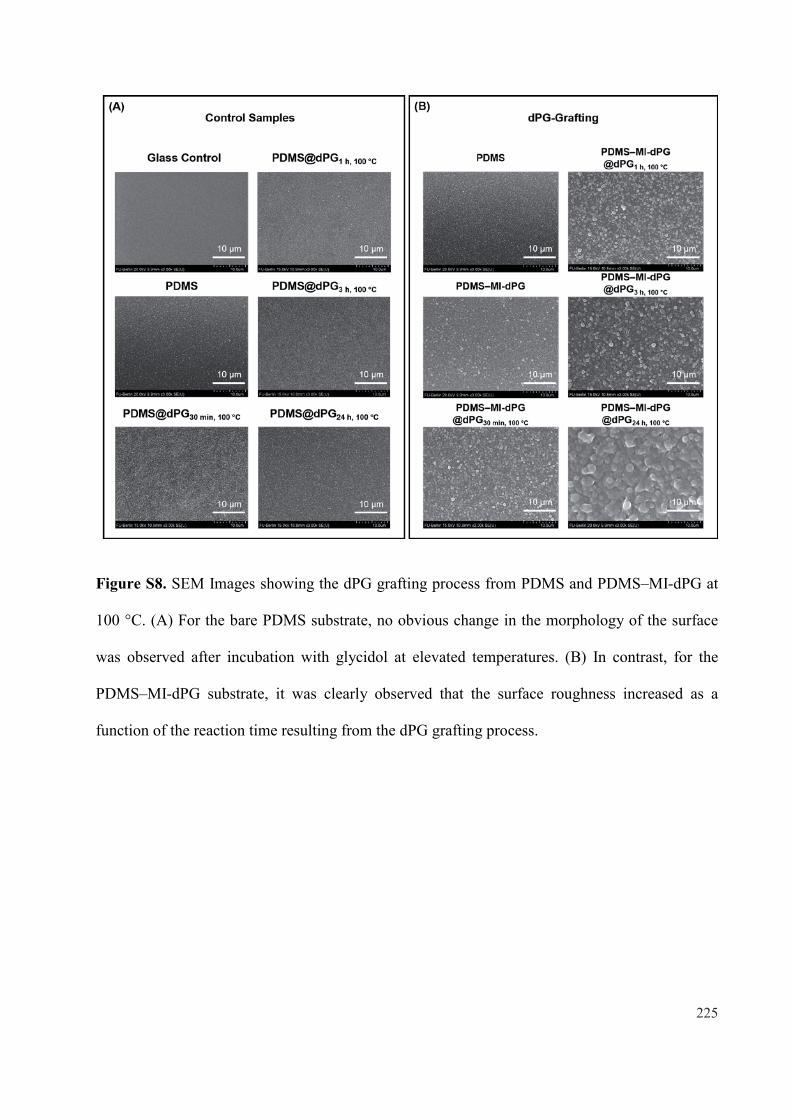
Figure S8. SEM Images showing the dPG grafting process from PDMS and PDMS–MI-dPG at
100 °C. (A) For the bare PDMS substrate, no obvious change in the morphology of the surface
was observed after incubation with glycidol at elevated temperatures. (B) In contrast, for the
PDMS–MI-dPG substrate, it was clearly observed that the surface roughness increased as a
function of the reaction time resulting from the dPG grafting process.
225

2.4. Cell Viability Results
Table S12. Cell number and viability quantification via LIVE/DEAD™ staining.
Substrate
Live Cells Dead Cells Total Cell Number Viability (%)
A549 DF-1 A549 DF-1 A549 DF-1 A549 DF-1
TCPS I 962 306 3 12 965 318 0.99 0.96
TCPS II 1044 333 7 12 1051 345 0.99 0.97
TCPS III 1129 295 0 4 1129 299 1 0.99
TCPS IV 1076 332 6 11 1082 343 0.99 0.97
TCPS V 919 - B 2 - B 921 - B 0.99 - B
TiO2 I 1031 78 2 11 1033 89 0.99 0.88
TiO2 II 956 86 5 8 961 94 0.99 0.91
TiO2 III 1098 92 5 3 2003 95 0.99 0.97
TiO2 IV 1205 75 3 5 1208 80 0.99 0.94
TiO2@dPGA I 935 207 2 11 937 218 0.99 0.95
TiO2@dPGA II 1088 110 2 13 1090 123 0.99 0.89
TiO2@dPGA III 861 172 1 23 862 195 0.99 0.88
226

TiO2@dPGA IV 855 249 9 11 864 260 0.99 0.96
TiO2–MI-dPG I 867 114 1 0 868 114 0.99 1.00
TiO2–MI-dPG II 840 179 0 6 840 185 1.00 0.97
TiO2–MI-dPG III 866 124 5 3 871 127 0.99 0.98
TiO2–MI-dPG IV 1110 183 9 1 1119 184 0.99 0.99
TiO2–MI-dPG@dPGA I 6 5 0 0 6 5 1.00 1.00
TiO2–MI-dPG@dPGA II 1 4 0 1 1 5 1.00 0.80
TiO2–MI-dPG@dPGA III 4 2 0 0 4 2 1.00 1.00
TiO2–MI-dPG@dPGA IV 3 2 0 0 3 2 1.00 1.00
PDMS I 1233 73 5 6 1238 79 0.99 0.92
PDMS II 1088 114 11 12 1099 126 0.99 0.90
PDMS III 1123 136 2 7 1125 143 0.99 0.95
PDMS IV 976 130 5 3 981 133 0.99 0.98
PDMS V 922 - B 7 - B 929 - B 0.99 - B
PDMS@dPGA I 881 407 40 33 921 440 0.95 0.93
PDMS@dPGA II 188 308 17 19 205 327 0.92 0.94
227
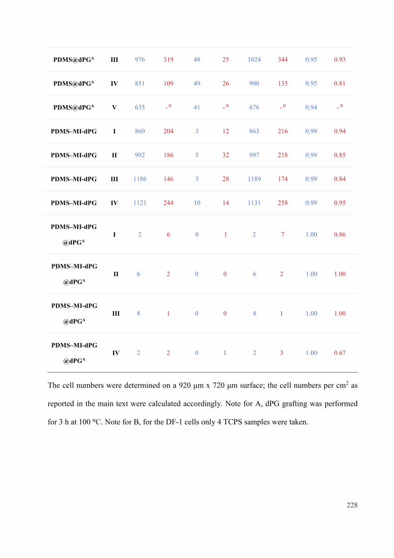
PDMS@dPGA III 976 319 48 25 1024 344 0.95 0.93
PDMS@dPGA IV 851 109 49 26 900 135 0.95 0.81
PDMS@dPGA V 635 - B 41 - B 676 - B 0.94 - B
PDMS–MI-dPG I 860 204 3 12 863 216 0.99 0.94
PDMS–MI-dPG II 992 186 5 32 997 218 0.99 0.85
PDMS–MI-dPG III 1186 146 3 28 1189 174 0.99 0.84
PDMS–MI-dPG IV 1121 244 10 14 1131 258 0.99 0.95
PDMS–MI-dPG
@dPGAI 2 6 0 1 2 7 1.00 0.86
PDMS–MI-dPG
@dPGAII 6 2 0 0 6 2 1.00 1.00
PDMS–MI-dPG
@dPGAIII 8 1 0 0 8 1 1.00 1.00
PDMS–MI-dPG
@dPGAIV 2 2 0 1 2 3 1.00 0.67
; the cell numbers per cm2 as
reported in the main text were calculated accordingly. Note for A, dPG grafting was performed
for 3 h at 100 °C. Note for B, for the DF-1 cells only 4 TCPS samples were taken.
228
3. LITERATURE
[1] A. O. Fitton, J. Hill, D. E. Jane, R. Millar, Synthesis 1987, 1987, 1140.
[2] A. Sunder, R. Hanselmann, H. Frey, R. Mülhaupt, Macromolecules 1999, 32, 4240.
[3] S. Roller, H. Zhou, R. Haag, Molecular Diversity 2005, 9, 305.
[4] H. e. al., ACS Applied Materials & Interfaces 2016, 8, 29117.
[5] Q. Wei, K. Achazi, H. Liebe, A. Schulz, P.-L. M. Noeske, I. Grunwald, R. Haag,
Angewandte Chemie International Edition 2014, 53, 11650.
[6] M. D. Abràmoff, P. J. Magalhães, S. J. Ram, Biophotonics international 2004, 11, 36.
229

4. APPENDIX
Figure S9. The XPS survey spectra of bare glass (which was used as the substrate
material for the immobilization of TiO2 and PDMS), TiO2, TiO2@dPG , 100 °C,
TiO2–MI-dPG50 °C, ATM, and TiO2–MI-dPG110 °C, HV.
230

Figure S10. The XPS survey spectra of TiO2–MI-dPG@dPG 80 °C/100 °C.
231
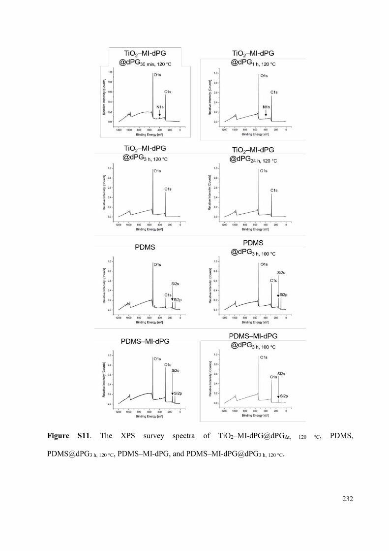
Figure S11. The XPS survey spectra of TiO2–MI-dPG@dPG 120 °C, PDMS,
PDMS@dPG3 h, 120 °C, PDMS–MI-dPG, and PDMS–MI-dPG@dPG3 h, 120 °C.
232

5. SUMMARY AND CONCLUSIONSIn this doctoral thesis novel mussel-inspired coatings for the prevention of biomaterial- and
shear-induced fouling were successfully developed. The formation of the MI-dPG coating on
TiO2 and its subsequent post-functionalization with lPG–b–OA11 or HO–PEG–NH2 substrates
were confirmed via CA, AFM, SEM, X-ray photoelectron spectroscopy (XPS), and streaming
current measurements. Furthermore, CA and XPS measurements confirmed the stability of the
lPG-functionalized system for at least one month in phosphate buffered saline and sodium
dodecyl sulfate solution at room temperature.
The bio- and hemocompatibility of the developed materials were assessed by
investigating the cytotoxicity, complement activating properties, and antifouling properties of
the novel coatings. Most importantly, the adhesion and activation of blood platelets was
investigated on the various substrates under static and flow conditions. When the proliferation
and viability of adenocarcinomic human alveolar basal epithelial cells (A549 cells) and chicken
fibroblast cells (DF-1 cells) were studied on the different coatings via LIVE/DEAD™ staining,
it was clearly observed that the introduction of lPG to MI-dPG-coated TiO2 prevented the
adhesion of both cell types. Furthermore, all lPG-functionalized samples showed high cell
viability, indicating that cell-repelling but highly biocompatible coatings were obtained.
Quantification of the C5a levels in PRP solutions that were exposed to the various coatings
showed slightly increased C5a levels in comparison to the negative control in all cases.
However, all observed C5a levels were significantly lower than those of the positive control,
indicating that the coatings did not induce any apparent complement activation. When the
protein fouling characteristics of the coatings were assessed by means of QCM-D, the strongest
reduction in unspecific protein adhesion was observed for the lPG-functionalized MI-dPG
coating (96% reduction for albumin and 99% reduction for fibrinogen in comparison to the
bare TiO2 substrate). Furthermore, SEM investigations clearly showed that the lPG-
functionalized surface inhibited the activation of platelets from PRP under static conditions.
The adhesion of platelets from whole blood under flow conditions was investigated using the
stagnation point flow model developed by Affeld et al.111-112, 274 The lowest platelet adhesion
was clearly observed for the lPG-functionalized MI-dPG coating (60% reduction in respect to
the native MI-dPG coating, 77% reduction in respect to the bare TiO2 substrate, and 86%
reduction in respect to the collagen positive control). The coating of a VAD with MI-dPG under
flow conditions was successfully performed. Visualization of the MI-dPG coating was
achieved by reacting the coating with a commercially available fluorophore under optimized
233
reaction conditions. The combined results showed that highly biocompatible, cell-, protein-,
and platelet-repelling surface coatings were obtained via the introduction of lPG–b–OA11 to
the MI-dPG coating. Furthermore, MI-dPG has proven itself as a suitable coating material for
the functionalization of VAD systems.
When MI-dPG-coated hydrophilic TiO2 and MI-dPG-coated hydrophobic PDMS were
incubated with bulk glycidol under elevated temperatures, a clear decrease in the CA as a
function of the reaction time and temperature was observed. Additionally, XPS confirmed the
increase of the C–O bond content as a result of the grafting process. Furthermore, when the
morphology of the surface was studied by means of SEM, a clear increase in the surface
roughness was observed resulting from the grafting process. The combined results showed the
successful grafting of dPG from the MI-dPG coating on hydrophilic TiO2 and hydrophobic
PDMS substrates. Furthermore, CA and XPS measurements showed that in the absence of the
MI-dPG coating, the grafting of dPG did not occur sufficiently. When the proliferation and
viability of A549 and DF-1 cells were investigated on the dPG-grafted MI-dPG coatings by
means of LIVE/DEAD™ staining, a strong reduction in the cell numbers of both cell types was
observed (> 95% in all cases) in respect to the uncoated TiO2 and PDMS substrates. However,
the observed cells showed high viability on the dPG-functionalized MI-dPG-coatings (> 88%
viability in all cases), showing that cell-repelling but highly biocompatible surfaces were
obtained.
To summarize, the hypothesis of the first paper of the thesis was confirmed: i.e., stable
substrate-independent antifouling systems were successfully created via the introduction of
lPG–b–OA11 and HO–PEG–NH2 to MI-dPG-coated TiO2. The hypothesis of the second paper
was also confirmed: i.e., the lPG-functionalized MI-dPG coating proofed itself as a highly
biocompatible antifouling coating for the effective inhibition platelet adhesion and activation
under static and flow conditions. Furthermore, the MI-dPG coating was identified as a suitable
coating material for the functionalization of VADs under flow conditions. Finally, the
hypothesis of the third paper was also confirmed: i.e., dPG was effectively grafted from MI-
dPG-coated hydrophilic TiO2 and from MI-dPG-coated hydrophobic PDMS, for the creation
of highly biocompatible but cell-repelling surfaces. Furthermore, the surface wettability and
surface roughness were precisely controlled by carefully adjusting the reaction times and
temperatures.
234

6. OUTLOOKIn the first project of this thesis, the stability of multivalently bound lPG–b–OA11 was clearly
demonstrated.180 However, the relation between the number of surface tethering groups and the
surface chain density was not investigated in the current work. Future works could utilize the
MI-dPG coating as a platform for the direct comparison of the antifouling properties of a wide
variety of hydrophilic polymers. The grafting density of these hydrophilic polymers could
potentially be tuned on the MI-dPG coating, by varying the amount of surface tethering groups
and by adjusting the polymer concentration of the secondary reagent during the post-
functionalization step. It is important to notice, that a direct comparison of the antifouling
surface properties of different hydrophilic polymers can only be made once surfaces with
identical surface chain densities are obtained.163 To the best of our knowledge, such a direct
comparison of the antifouling surface properties for multi-layer hydrophilic polymeric systems
has not been performed yet.
The second project of this thesis gave a proof-of-concept for the use of mussel-inspired
PG-based coatings for the prevention of biomaterial- and shear-induced thrombosis. However,
the efficiency of these coatings was only shown in vitro so far. Future works might focus on
the functionalization of shunts and/or metallic stents for in vivo applications. Next, a VAD
could be coated with an optimized version of the PG-based system for further in vivo testing
under high shear conditions. Future studies could also assess the use of lPG and dPG
monolayers as hydrophilic bioinert antithrombogenic surface coatings.14, 181, 195
In the third project of this thesis, MI-dPG was utilized as a platform for the grafting of
dPG from the surface. Besides glycidol, other glycidyl ether such as dodecyl glycidyl ether
(DGE) or glycidyl 2,2,3,3,4,4,5,5-octafluoropentyl ether (GOFE) could potentially be grafted
from the MI-dPG coating, for the creation of surfaces with superhydrophobic wetting
properties. Furthermore, the catechol moieties of the MI-dPG coating could be utilized for the
immobilization of antibacterial AgNPs, prior to the grafting of hydrophobic glycidyl ether
monomers. By applying this strategy, the AgNPs would be protected from aqueous media by
a grafted hydrophobic layer, potentially preventing the removal of the AgNPs in the form of
Ag+ ions (resulting from oxidation). As a result, the AgNPs could reside longer on the surface,
possibly leading to sustained antibacterial activity via the release of reactive oxygen species.
235
7. KURZZUSAMMENFASSUNGDiese Doktorarbeit beschreibt die erfolgreiche Entwicklung neuartiger, von Muscheln
inspirierter Beschichtungen zur Verhinderung von biomaterial- und scherinduziertem Fouling.
Die Bildung der MI-dPG-Beschichtung auf TiO2 und ihre anschließende Funktionalisierung
mit lPG–b–OA11- oder HO–PEG–NH2-Substraten wurde mittels Kontaktwinkelmessungen,
Rasterkraftmikroskopie (AFM), Rasterelektronenmikroskopie (REM), Röntgen-
Photoelektronen-spektroskopie (XPS) und Strömungsstrommessungen nachgewiesen. Darüber
hinaus bestätigten Kontaktwinkel- und XPS-Messungen die Stabilität des lPG-
funktionalisierten Systems für mindestens einen Monat in phosphatgepufferter Kochsalz- und
Natrium-laurylsulfatlösung bei Raumtemperatur.
Die Bio- und Hämokompatibilität der neuentwickelten Materialien wurde mittels
Untersuchung der Zytotoxizität, komplementaktivierender Eigenschaften und Antifouling-
Eigenschaften bestimmt. Weiterhin standen vor allem die Adhäsion und Aktivierung von
Blutplättchen auf den verschiedenen Substraten unter statischen und Fließbedingungen im
Fokus. Bei der Charakterisierung von Proliferation und Lebensfähigkeit von
adenokarzinomischen humanen alveolären Basalepithelzellen (A549-Zellen) und
Hühnerfibroblastenzellen (DF-1-Zellen) auf den verschiedenen Beschichtungen mittels
LIVE/DEAD™-Färbung, konnte gezeigt werden, dass die Adhäsion dieser beiden Zelltypen
durch Einführung von lPG auf MI-dPG-beschichtetem TiO2 verhindert wird. Darüber hinaus
zeigten alle lPG-funktionalisierten Proben eine hohe Zellviabilität, was darauf hinweist, dass
zellabweisende, aber hoch biokompatible Beschichtungen erhalten wurden. Die
Quantifizierung der C5a-Gehalte in PRP (thrombozytenreiches Plasma) Lösungen, die den
verschiedenen Beschichtungen ausgesetzt waren, zeigte in allen Fällen leicht erhöhte C5a-
Gehalte im Vergleich zur Negativkontrolle. Alle beobachteten C5a-Gehalte waren jedoch
signifikant niedriger als die der Positivkontrolle, was darauf hindeutet, dass die
Beschichtungen keine offensichtliche Komplementaktivierung induzierten. Bei der
Beurteilung der Proteinfouling der Beschichtungen mit Hilfe von Quarzkristall-
Mikrowaagenmessungen mit Dissipationsmonitoring (QCM-D) wurde die stärkste Reduktion
der unspezifischen Proteinadhäsion bei der lPG-funktionalisierten MI-dPG-Beschichtung
beobachtet (96% Reduktion für Albumin und 99% Reduktion für Fibrinogen im Vergleich zum
blanken TiO2-Substrat). Darüber hinaus zeigten REM-Untersuchungen eindeutig, dass die
lPG-funktionalisierte Oberfläche die Aktivierung von Thrombozyten aus
thrombozytenreichem Plasma unter statischen Bedingungen hemmt. Die Adhäsion von
236
Thrombozyten aus Vollblut unter Flussbedingungen wurde mit dem von Affeld et al.
entwickelten Stagnationspunkt-Flussmodell untersucht. Die geringste Thrombozytenadhäsion
wurde eindeutig für die lPG-funktionalisierte MI-dPG-Beschichtung beobachtet (60%
Reduktion gegenüber der nativen MI-dPG-Beschichtung, 77% Reduktion gegenüber dem
blanken TiO2-Substrat und 86% Reduktion gegenüber der Kollagenpositivkontrolle). Die
Beschichtung eines Ventrikelunterstützungssystems (VAD) mit MI-dPG unter
Fließbedingungen wurde erfolgreich durchgeführt. Die Visualisierung der MI-dPG-
Beschichtung wurde durch Reaktion der Beschichtung mit einem kommerziell erhältlichen
Fluorophor unter optimierten Reaktionsbedingungen erreicht. Die kombinierten Ergebnisse
zeigten, dass durch die Immobilisierung von lPG auf die MI-dPG-Beschichtung hoch
biokompatible, zell-, protein- und plättchenabweisende Oberflächenbeschichtungen erzielt
wurden. Darüber hinaus hat sich MI-dPG als geeignetes Beschichtungsmaterial für die
Funktionalisierung von VAD-Systemen bewährt.
Bei der Inkubation von MI-dPG-beschichtetem hydrophilem TiO2 und MI-dPG-
beschichtetem hydrophobem PDMS mit Bulkglycidol unter erhöhten Temperaturen, konnte
eine deutliche Abnahme der Kontaktwinkel in Abhängigkeit von der Reaktionszeit und
Temperatur beobachtet werden. Zusätzlich bestätigte XPS den Anstieg des C–O-
Bindungsgehalts als Folge des Grafting-Prozesses. Darüber hinaus wurde bei der
Untersuchung der Oberflächenmorphologie mittels REM eine deutliche Zunahme der
Oberflächenrauhigkeit als Folge des Graftings beobachtet. Die kombinierten Ergebnisse
zeigten das erfolgreiche Grafting von dPG der MI-dPG-Beschichtung auf hydrophile TiO2-
und hydrophobe PDMS-Substrate. Darüber hinaus zeigten Kontaktwinkel- und XPS-
Messungen, dass in Abwesenheit der MI-dPG-Beschichtung die Grafting von dPG nicht
ausreichend erfolgte. Bei der Untersuchung der Proliferation und Lebensfähigkeit von A549-
und DF-1-Zellen auf den dPG-funktionalisierten MI-dPG-Beschichtungen mittels
LIVE/DEAD™-Färbung wurde eine starke Reduktion der Zellzahlen beider Zelltypen (> 95%
in allen Fällen) im Vergleich zu den unbeschichteten TiO2- und PDMS-Substraten beobachtet.
Die untersuchten Zellen zeigten jedoch eine hohe Viabilität auf den dPG-funktionalisierten
MI-dPG-Beschichtungen (> 88% Viabilität in allen Fällen), sodass zellabweisende, aber hoch
biokompatible Oberflächen erzielt wurden.
Zusammenfassend konnte die Hypothese aus der ersten Veröffentlichung dieser Arbeit
bestätigt werden: durch die Einführung von lPG–b–OA11 und HO–PEG–NH2 zu MI-dPG-
beschichtetem TiO2 wurden erfolgreich stabile substratunabhängige Antifoulingsysteme
237

geschaffen. Auch die Hypothese des zweiten Manuskripts wurde bestätigt: die lPG-
funktionalisierte MI-dPG-Beschichtung erwies sich als hoch biokompatible Antifouling-
Beschichtung für die effektive Inhibierung der Plättchenhaftung und -aktivierung unter
statischen und Fließbedingungen. Darüber hinaus wurde die MI-dPG-Beschichtung als ein
geeignetes Beschichtungsmaterial für die Funktionalisierung von VADs unter
Fließbedingungen identifiziert. Schließlich wurde auch die Hypothese des dritten Manuskripts
bestätigt: dPG wurde effektiv aus MI-dPG-beschichtetem hydrophilem TiO2 und aus MI-dPG-
beschichtetem hydrophoben PDMS gegrafted, um stark biokompatible, aber zellabweisende
Oberflächen zu erzeugen. Darüber hinaus konnten die Oberflächenbenetzbarkeit und die
Oberflächenrauhigkeit durch sorgfältige Einstellung der Reaktionszeiten und Temperaturen
präzise gesteuert werden.
238

8. ABBREVIATION LIST
A549: adenocarcinomic human alveolar
basal epithelial cells
AC: alternating current
ADP: adenosine diphosphate
AFM: atomic force microscopy
AgNP: silver nanoparticle
CA: contact angle
CF8: fluoroundecanoyl chloride
CVD: cardiovascular disease
DF-1: chicken fibroblast cells
DGE: dodecyl glycidyl ether
DLC: diamond-like carbon
DOPA: 3,4–dihydroxyphenyl-L-alanine
dPG: dendritic polyglycerol
dPG-Cat(x): x% catechol functionalized
dendritic polyglycerol
ELISA: enzyme-linked immunosorbent
assay
GOFE: glycidyl 2,2,3,3,4,4,5,5-octa
fluoropentyl ether
GPIIb/IIIa: glycoprotein IIb/IIIa
HMWK: high molecular weight kininogen
KK: kallikrein
LBL: layer-by-layer
lPG: linear polyglycerol
MAC: membrane attack complex
mfp: mussel-foot protein
MI-dPG: mussel-inspired dPG
NO: nitric oxide
OA: oligo-amine
PDA: polydopamine
PDMS: polydimethylsiloxane
PEG: poly(ethylene glycol)
PES: polyethersulfone
PF4: platelet factor 4
PG: polyglycerol
PK: prekallikrein
PMN: polymorphonuclear
PRP: platelet rich plasma
PS: Polystyrene
PTFE: polytetrafluoroethylene
PU: polyurethane
QCM-D: quartz crystal microbalance with
dissipation monitoring
SAM: self-assembled monolayer
SEM: scanning electron microscopy
TF: tissue factor
TiN: titanium nitride
TiO2: titanium dioxide
TXA2: thromboxane A2
UV: ultraviolet
VAD: ventricular assist device
vWF: von Willebrand factor
XPS: X-ray photoelectron spectroscopy
239

9. LITERATURE1. E. Wilkins, L. Wilson, K. Wickramasinghe, P. Bhatnagar, J. Leal, R. Luengo-
Fernandez, R. Burns, M. Rayner, N. Townsend, European cardiovascular disease
statistics 2017 2017.
2. P. Shah, U.S. Tantry, K. P. Bliden, P. A. Gurbel, J. Heart Lung Transpl. 2017, 36, 1164.
3. L. D. C. Casa, D. N. Ku, Annu. Rev. Biomed. Eng. 2017, 19, 415.
4. C. Cheng, S. Sun, C. Zhao, J. Mater. Chem. B 2014, 2, 7649.
5. J. Zhu, R. E. Marchant, Biomacromolecules 2006, 7, 1036.
6. N. Hadjesfandiari, M. Weinhart, J. N. Kizhakkedathu, R. Haag, D. E. Brooks, Adv.
Healthc. Mater. 2018, 7, 1700839.
7. X. Ding, C. Yang, T. P. Lim, L. Y. Hsu, A. C. Engler, J. L. Hedrick, Y.-Y Yang,
Biomaterials 2012, 33, 6593.
8. D.-C. Sin, H.-L Kei, X. Miao, Expert Rev. of Med. Devices 2009, 6, 51.
9. C. D. Bain, E. B. Troughton, Y. T. Tao, J. Evall, G. M. Whitesides, R. G. Nuzzo, J.
Am. Chem. Soc. 1989, 111, 321.
10. A. Y. Fadeev, Y. V. Kazakevich, Langmuir 2002, 18, 2665.
11. D. Kubies, L. Machová, E. Brynda, J. Lukáš, F. Rypáček, J. Mater. Sci. Mater. Med.
2003, 14, 143.
12. C. Boura, P. Menu, E. Payan, C. Picart, J. C. Voegel, S. Muller, J. F. Stoltz,
Biomaterials 2003, 24, 3521.
13. P. Petrov, G. Georgiev, D. Momekova, G. Momekov, C. B. Tsvetanov, Polymer 2010,
51, 2465.
14. L. Yu, Y. Hou, C. Cheng, C. Schlaich, P.-L M. Noeske, Q. Wei, R. Haag, ACS Appl.
Mater. Inter. 2017, 9, 44281.
15. P. Bertrand, A. Jonas, A. Laschewsky, R. Legras, Macromol. Rapid Commun. 2000,
21, 319.
16. C. Freij-Larsson, T. Nylander, P. Jannasch, B. Wesslén, Biomaterials 1996, 17, 2199.
17. N. Uriel, J. Han, K. A. Morrison, N. Nahumi, M. Yuzefpolskaya, A. R. Garan, J.
Duong, P. C. Colombo, H. Takayama, S. Thomas, J. Heart Lung Transpl. 2014, 33, 51.
18. W.-T. Wu, F. Yang, J. Wu, N. Aubry, M. Massoudi, J. F. Antaki, Sci. Rep. 2016, 6,
38025.
19. F. Yin, H.-K. Shin, Y.-S. Kwon, Thin Solid Films 2006, 499, 1.
20. C. Qiu, S. Qi, C. Y. Tang, J. Membr. Sci. 2011, 381, 74.
240

21. H. Lee, S. M. Dellatore, W. M. Miller, P. B. Messersmith, Science 2007, 318, 426.
22. H.-C. Yang, J. Luo, Y. Lv, P. Shen, Z.-K. Xu, J. Membr. Sci. 2015, 483, 42.
23. Y. Cho, S. Y. Seo, B. J. Park, Y. K. Joung, D. K. Han, Macromol. Res. 2017, 25, 841.
24. Q. Wei, B. Li, N. Yi, B. Su, Z. Yin, F. Zhang, J. Li, C. Zhao, J. Biomed. Mater. Res. A
2011, 96A, 38.
25. R. Biran, D. Pond, Adv. Drug Deliv. Rev. 2017, 112, 12.
26. H.-Y. Mi, X. Jing, J. A. Thomsom, L.-S. Turng, J. Mater. Chem. B 2018, 6, 3475.
27. R. Luo, X. Wang, J. Deng, H. Zhang, M. F. Maitz, L. Yang, J. Wang, N. Huang, Y.
Wang, Colloids Surface. B 2016, 144, 90.
28. M. Irfan, A, Idris, Mater. Sci. Eng. C 2015, 56, 574.
29. M. Navarro, A. Michiardi, O. Castaño, J. A. Planell, J. R. Soc. Interface 2008, 5, 1137.
30. L. Xue, H. P. Greisler, J. Vasc. Surg. 2003, 37, 472.
31. I. H. Jaffer, J. C. Fredenburgh, J. Hirsh, J. I. Weitz, J. Thromb. Haemost. 2015, 13, S72.
32. M. Weber, H. Steinle, S. Golombek, L. Hann, C. Schlensak, H. P. Wendel, M. Avci-
Adali, Front. Bioeng. Biotechnol. 2018, 6, 99.
33. R. Paniccia, R. Priora, A. A. Liotta, R. Abbate, Vasc. Health Risk Manag. 2015, 11,
133.
34. B. P. Nuyttens, T. Thijs, H. Deckmyn, K. Broos, Thromb. Res. 2011, 127, S26.
35. L. Yang, L. Han, Q. Liu, Y. Xu, L. Jia, Acta Biomater. 2017, 64, 187.
36. L.-C. Xu, J. W. Bauer, C. A. Siedlecki, Colloid Surface. B 2014, 124, 49.
37. W.-B. Tsai, J. M. Grunkemeier, T. A. Horbett, J. Biomed. Mater. Res. 1999, 44, 130.
38. L. Zhang, B. Casey, D. K. Galanakis, C. Marmorat, S. Skoog, K. Vorvolakos, M.
Simon, M. H. Rafailovich, Acta Biomater. 2017, 54, 164.
39. A. J. Gale, Toxicol. Pathol. 2011, 39, 273.
40. R. D. Allen, L. R. Zacharski, S. T. Widirstky, R. Rosenstein, L. M. Zaitlin, D. R.
Burgess, J. Cell Biol. 1979, 83, 126.
41. S. N. Rodrigues, I. C. Gonçalves, M. C. L. Martins, M. A. Barbosa, B. D. Ratner,
Biomaterials 2006, 27, 5357.
42. T. Xiang, T. Lu, Y. Xie, W.-F. Zhao, S.-D. Sun, C.-S. Zhao, Acta Biomater. 2016, 40,
162.
43. I. C. Gonçalves, M. C. L. Martins, M. A. Barbosa, E. Naeemi, B. D. Ratner, J. Biomed.
Mater. Res. A 2009, 89A, 642.
44. C. J. Nonckreman, S. Fleith, P. G. Rouxhet, C. C. Dupont-Gillain, Colloid. Surface. B
2010, 77, 139.
241

45. B. Sivaraman, R. A. Latour, Biomaterials 2010, 31, 832.
46. Y. Hu, J. Jin, H. Liang, X. Ji, J. Yin, W. Jiang, Langmuir 2016, 32, 4086.
47. S. P. Grover, N. Mackman, Arterioscler. Thromb. Vasc. Biol. 2019, 39, 331.
48. H. E. Caputo, J. E. Straub, M. W. Grinstaff, Chem. Soc. Rev. 2019, 48, 2338.
49. J. Bäck, J. Sanchez, G. Elgue, K. N. Ekdahl, B. Nilsson, Biochem. Bioph. Res. Co.
2010, 391, 11.
50. L. F. Brass, Chest 2003, 124, 18S.
51. Z. Hofman, S. de Maat, C. E. Hack, C. Maas, Clin. Rev. Allerg. Immu. 2016, 51, 152.
52. R. C. Wiggins, B. N. Bouma, C. G. Cochrane, J. H. Griffin, PNAS 1977, 74, 4636.
53. L. Faxälv, T. Lindahl, http://platelets.se/biomaterial/, Accessed 28.05.20.
54. O. D. Ratnoff, J. M. Rosenblum, Am. J. Med. Sci. 1958, 25, 160.
55. J. Margolis, Aust. J. Exp. Biol. Med. Sci. 1961, 39, 249.
56. F. van der Graaf, F. Keus, R. Vlooswijk, B. N. Bouma, Blood 1982, 59, 1225.
57. D. L. Tankersley, B. M. Alving, J. Finlayson, Blood 1983, 62, 448.
58. R. C. Wiggins, C. C. Cochrane, J. Exp. Med. 1979, 150, 1122.
59. D. Kudela, S. A. Smith, A. May-Masnou, G. B. Braun, A. Pallaoro, C. K. Nguyen, T.
T. Chuong, S. Nownes, R. Allen, N. R. Parker, H. H. Rashidi, J. H. Morrissey, G. D.
Stucky, Angew. Chem. Int. Ed. 2015, 54, 4018.
60. S. A. Smith, N. J. Mutch, D. Baskar, P. Rohloff, R. Docampo, J. H. Morrissey, PNAS
2006, 103, 903.
61. P. E. J. van der Meijden, I. C. A. Munnix, J. M. Auger, J. W. P. Govers-Riemslag, J.
M. E. M. Cosemans, M. J. E. Kuijpers, H. M. Spronk, S. P. Watson, T. Renné, J. W.
M. Heemskerk, Blood 2009, 114, 881.
62. Y. Yan, L. C. Xu, E. A. Vogler, C. A. Siedlecki, Hemocompatibility of Biomaterials
for Clinical Applications 2018, 1 Ed., 3.
63. Y. Wu, Thromb. J. 2015, 13, 17.
64. J. D. Loike, B. Sodeik, L. Cao, S. Leucona, J. I. Weitz, P. A. Detmers, S. D. Wright, S.
C. Silverstein, PNAS 1991, 88, 1044.
65. S. D. Wright, J. I. Weitz, A. J. Huang, S. M. Levin, S. C. Silverstein, J. D. Loike, PNAS
1988, 85, 7734.
66. D. Morley, I. Feuerstein, Thromb. Haemost. 1989, 62, 1023.
67. T. Imamura, H. Kaneda, S. Nakamura, Lab. Investig. 2002, 82, 1287.
68. H. Todoroki, S. Nakamura, A. Higure, K. Okamoto, S. Takeda, N. Nagata, H. Itoh, K.
Ohsato, Surgery 2000, 127, 209.
242

69. T. Lisman, Cell Tissue Res. 2018, 371, 567.
70. L. Vroman, A. L. Adams, Surf. Sci. 1969, 16, 438.
71. J. Andersson, K. N. Ekdahl, R. Larsson, U. R. Nilsson, B. Nilsson, J. Immunol. 2002,
168, 5786.
72. M. Noris, G. Remuzzi, Semin. Nephrol. 2013, 33, 479.
73. H. Rus, C. Cudrici, F. Niculescu, Immunol. Res. 2005, 33, 103.
74. Y. N. V. Reddy, A. M. Siedlecki, J. M. Francis, Curr. Opin. Nephrol. Hy. 2017, 26,
123.
75. B. Nilsson, K. N. Ekdahl, T. E. Mollnes, J. D. Lambris, Mol. Immunol. 2007, 44, 82.
76. S. P. Jackson, W. S. Nesbitt, E. Westein, J. Thromb. and Haemost. 2009, 7, 17.
77. W. S. Nesbitt, E. Westein, F. J. Tovar-Lopez, E. Tolouei, A. Mitchell, J. Fu, J. Carberry,
A. Fouras, S. P. Jackson, Nat. Med. 2009, 15, 665.
78. C. C. Helms, M. Marvel, W. Zhao, M. Stahle, R. Vest, G. J. Kato, J. S. Lee, G. Christ,
M. T. Gladwin, R. R. Hantgan, D. B. Kim-Shapiro, J. Thromb. and Haemost. 2013, 11,
2148.
79. A. Gaarder, J. Jonsen, S. Laland, A. Hellem, P. A. Owren, Nature 1961, 192, 531.
80. S. Sinn, T. Scheuermann, S. Deichelbohrer, G. Ziemer, H. P. Wendel, J. Mater. Sci.
Mater. Med. 2011, 22, 1521.
81. K. Stang, S. Krajewski, B. Neumann, J. Kurz, M. Post, S. Stoppelkamp, S. Fennrich,
M. Avci-Adali, D. Armbruster, C. Schlensak, I. A. Burgener, H. P. Wendel, T. Walker,
Mater. Sci. Eng. C 2014, 42, 422.
82. M. V. Homann, D. Johansson, H. Wallen, J. Sanchez, J. Biomed. Mater. Res. B 2016,
104, 1359.
83. B. I. Cerda-Cristerna, H. Flores, A. Pozos-Guillén, E. Pérez, C. Sevrin, C. Grandfils, J.
Control. Release 2011, 153, 269.
84. H. Stoll, H. Steinle, K. Stang, S. Kunnakattu, L. Scheideler, B. Neumann, J. Kurz, I.
Degenkolbe, N. Perle, C. Schlensak, H. P. Wendel, M. Avci-Adali, Macromol. Biosci.
2017, 17, 1600252.
85. L. D. C. Casa, D. H. Deaton, D. N. Ku, J. Vasc. Surg. 2015, 61, 1068.
86. Y. Cadroy, T. Horbett, S. Hanson, J. Lab. Clin. Med. 1989, 113, 436.
87. D. M. Wootton, D. N. Ku, Annu. Rev. Biomed. Eng. 1999, 1, 299.
88. D. N. Ku, C. J. Flannery, Biorheology 2007, 44, 273.
89. D. L. Bark Jr., A. N. Para, D. N. Ku, Biotechnol. Bioeng. 2012, 109, 2642.
243

90. K. B. Neeves, A. A. Onasoga, R. R. Hansen, J. J. Lilly, D. Venckunaite, M. B. Sumner,
A. T. Irish, G. Brodsky, M. J. Manco-Johnson, J. A. Di Paola, PloS one 2013, 8, e54680.
91. A. Para, D. Bark, D., A. Lin, D. Ku, Ann. Biomed. Eng. 2011, 39, 1961.
92. M. Mehrabadi, L. D. C. Casa, C. K. Aidun, D. N. Ku, Ann. Biomed. Eng. 2016, 44,
2339.
93. A. Zydney, C. K. Colton, PCH 1988, 10, 77.
94. S. W. Schneider, S. Nuschele, A. Wixforth, C. Gorzelanny, A. Alexander-Katz, R. R.
Netz, M. F. Schneider, PNAS 2007, 104, 7899.
95. P. A. Holme, U. Ørvim, M. J. A. G. Hamers, N. O. Solum, F. R. Brosstad, R. M.
Barstad, K. S. Sakariassen, Arterioscler. Thromb. Vasc. Biol. 1997, 17, 646.
96. A. Jordan, T. David; S. Homer‐Vanniasinkam, A. Graham, P. Walker, Biorheology
2004, 41, 641.
97. P. Aarts, S. Van Den Broek, G. W. Prins, G. Kuiken, J. J. Sixma, R. M. Heethaar,
Arteriosclerosis 1988, 8, 819.
98. J. E. Sadler, Annu. Rev. Biochem. 1998, 67, 395.
99. Y. Ikeda, M. Handa, K. Kawano, T. Kamata, M. Murata, Y. Araki, H. Anbo, Y. Kawai,
K. Watanabe, I. Itagaki, J. Clin. Invest. 1991, 87, 1234.
100. Z. M. Ruggeri, J. N. Orje, R. Habermann, A. B. Federici, A. J. Reininger, Blood 2006,
108, 1903.
101. T. V. Colace, S. L. Diamond, Arterioscler. Thromb. Vasc. Biol. 2013, 33, 105.
102. C. C. Mohan, K. P. Chennazhi, D. Menon, Acta Biomater. 2013, 9, 9568.
103. C. L. Haycox, B. D. Ratner, J. Biomed. Mater. 1993, 27, 1181.
104. U. Streller, C. Sperling, J. Hübner, R. Hanke, C. Werner, J. Biomed. Mater. Res. B
2003, 66B, 379.
105. M. F. Maitz, C. Sperling, T. Wongpinyochit, M. Herklotz, C. Werner, F. P. Seib,
Nanomed.-Nanotechnol. 2017, 13, 2633.
106. W. G. McClung, D. E. Babcock, J. L. Brash, J. Biomed. Mater. Res. A 2007, 81A, 644.
107. D.-A. Wang, J. Ji, C.-Y. Gao, G.-H. Yu, L.-X. Feng, Biomaterials 2001, 22, 1549.
108. R. Van Kruchten, J. M. E. M. Cosemans, J. W. M. Heemskerk, Platelets 2012, 23, 229.
109. J. M. Lackner, W. Waldhauser, P. Hartmann, F. Bruckert, M. Weidenhaupt, R. Major,
M. Sanak, M. Wiesinger, D. Heim, J. Funct. Biomater. 2012, 3, 283.
110. E. Gutierrez, B. G. Petrich, S. J. Shattil, M. H. Ginsberg, A. Groisman, A. Kasirer-
Friede, Lab on a Chip 2008, 8, 1486.
244
111. K. Affeld, A. J. Reininger, J. Gadischke, K. Grunert, S. Schmidt, F. Thiele, Artif.
Organs 1995, 19, 597.
112. K. Affeld, S. Stefansdottir, J. Schaller, U. Kertzscher, Biomed. Tech. 2014, 59, 11.
113. L. J. Wurzinger, P. Blasberg, F. Horii, H. Schmid-Schöbein, Thromb. Res. 1986, 44,
401.
114. L. Wurzinger, P. Blasberg, M. Van de Loecht, W. Suwelack, H. Schmid-Schönbein,
Biorheology 1984, 21, 649.
115. J. Deng, X. Liu, L. Ma, C. Cheng, W. Shi, C. Nie, C. Zhao, ACS Appl. Mater. Inter.
2014, 6, 21603.
116. L. Ma, C. Cheng, C. He, C. Nie, J. Deng, S. Sun, C. Zhao, C., ACS Appl. Mater. Inter.
2015, 7, 26050.
117. L. Ma, C. Cheng, C. Nie, C. He, J. Deng, L. Wang, Y. Xia, C. Zhao, J. Mater. Chem.
B 2016, 4, 3203.
118. N. Hadjesfandiari, P. Schubert, S. Fallah Toosi, Z. Chen, B. Culibrk, S. Ramirez‐Arcos,
D. V. Devine, D. E. Brooks, Transfusion 2016, 56, 2808.
119. B. Balakrishnan, D. Kumar, Y. Yoshida, A. Jayakrishnan, Biomaterials 2005, 26, 3495.
120. K. Affeld, J. Schaller, T. Wölken, T. Krabatsch, U. Kertzscher, Biointerphases 2016,
11, 029804.
121. I. H. A. Badr, M. Gouda, R. Abdel-Sattar, H. E. M. Sayour, Carbohydr. Polym. 2014,
99, 783.
122. W. J. Sung, K. Na, Y. H. Bae, Sensors Actuat. B-Chem. 2004, 99, 393.
123. L. K. Von Segesser, Coatings for Biomedical Applications, 2012, 1 Ed., 251.
124. S. Thelin, L. Bagge, J. Hultman, J. Borowiec, L. Nilsson, J. Thorelius, Eur. J.
Cardiothorac. Surg. 1991, 5, 486.
125. X. Wang, N. Shi, Y. Chen, C. Li, X. Du, W. Jin, Y. Chen, P. R. Chang, Bio.-Med.
Mater. Eng. 2012, 22, 143.
126. M. F. Maitz, U. Freudenberg, M. V. Tsurkan, M. Fischer, T. Beyrich, C. Werner, Nat.
Commun. 2013, 4, 2168.
127. J. Li, X.-J. Huang, J. Ji, P. Lan, J. Vienken, T. Groth, Z.-K. Xu, Macromol. Biosci.
2011, 11, 1218.
128. P.-Y. Tseng, S. M. Rele, X.-L. Sun, E. L. Chaikof, Biomaterials 2006, 27, 2627.
129. M.-C. Yang, W.-C. Lin, J. Polym. Res. 2002, 9, 201.
130. F. Y. Mahlicli, S. A. Altinkaya, J. Mater. Sci. Mater. Med. 2013, 24, 533.
245
131. S. Claudia, H. Milan, B. Eduard, S. Uwe, W. Carsten, J. Biomed. Mater. Res. A 2006,
76A, 681.
132. C. Sperling, U. Konig, G. Hermel, C. Werner, M. Muller, F. Simon, K. Grundke, H. J.
Jacobasch, V. N. Vasilets, Y. Ikada, J. Mater. Sci. Mater. Med. 1997, 8, 789.
133. S. Alibeik, S. Zhu, J. W. Yau, J. I. Weitz, J. L. Brash, Acta Biomaterialia 2011, 7, 4177.
134. M. Hoffmann, B. Huppertz, R. Horres, H. Baumann, R. Keller, Materwiss. Werksttech.
2001, 32, 110.
135. S. Sarrazin, W. C. Lamanna, J. D. Esko, CSH Perspect. Biol. 2011, 3, a004952.
136. J. Lahann, D. Klee, W. Pluester, H. Hoecker, Biomaterials 2001, 22, 817.
137. Z. Yang, Q. Tu, M. F. Maitz, S. Zhou, J. Wang, N. Huang, Biomaterials 2012, 33, 7959.
138. S. C. Freitas, T. B. Cereija, A. C. Figueiredo, H. Osório, P. J. B. Pereira, M. A. Barbosa,
M. C. L. Martins, Acta Biomater. 2012, 8, 4101.
139. R. Xu, Q. Feng, Y. He, F. Yan, L. Chen, Y. Zhao, J. Biomed. Mater. Res. A 2017, 105,
178.
140. M. C. Porté-Durrieu, C. Aymes-Chodur, N. Betz, C. Baquey, J. Biomed. Mater. Res.
2000, 52, 119.
141. J. Gu, X. Yang, H. Zhu, Mater. Sci. Eng. C 2002, 20, 199.
142. C. Nie, L. Ma, Y. Xia, C. He, J. Deng, L. Wang, C. Cheng, S. Sun, C. Zhao, J. Membr.
Sci. 2015, 475, 455.
143. T. Xiang, L.-S. Zhang, R. Wang, Y. Xia, B.-H. Su, C.-S Zhao, J. Colloid Interface Sci.
2014, 432, 47.
144. L. Ma, H. Qin, C. Cheng, Y. Xia, C. He, C. Nie, L. Wang, C. Zhao, J. Mater. Chem. B
2014, 2, 363.
145. F. Ran, S. Nie, J. Li, B. Su, S. Sun, C. Zhao, Macromol. Biosci. 2012, 12, 116.
146. K. A. Woodhouse, P. Klement, V. Chen, M. B. Gorbet, F. W. Keeley, R. Stahl, J. D.
Fromstein, C. M. Bellingham, Biomaterials 2004, 25, 4543.
147. E. M. Srokowski, P. H. Blit, W. G. McClung, J. L. Brash, J. P. Santerre, K. A.
Woodhouse, J. Biomater. Sci. Polym. Ed. 2011, 22, 41.
148. S. W. Jordan, C. A. Haller, R. E. Sallach, R. P. Apkarian, S. R. Hanson, E. L. Chaikof,
Biomaterials 2007, 28, 1191.
149. V. N. Varu, N. D. Tsihlis, M. R. Kibbe, Vasc. Endovasc. Surg. 2009, 43, 121.
150. C. R. Arciola, D. Campoccia, L. Montanaro, Nat. Rev. Microbiol. 2018, 16, 397.
151. M. R. Beresford, P. W. Andrew, G. Shama, J. Appl. Microbiol. 2001, 90, 1000.
152. J. Genzer, K. Efimenko, Biofouling 2006, 22, 339.
246

153. M. Elimelech, W. A. Phillip, Science 2011, 333, 712.
154. J. Y. Lichtenberg, Y. Ling, S. Kim, Sensors 2019, 19, 2488.
155. N. Wisniewski, M. Reichert, Colloid. Surface. B 2000, 18, 197.
156. W. Zimmerli, Best Pract. Res. Cl. Rh. 2006, 20, 1045.
157. K. Prime, G. Whitesides, Science 1991, 252, 1164.
158. H. Lee, S. M. Dellatore, W. M. Miller, P. B. Messersmith, Science 2007, 318, 426.
159. Y. Gidi, S. Bayram, C. J. Ablenas, A. S. Blum, G. Cosa, ACS Appl. Mater. Inter. 2018,
10, 39505.
160. M. Huebner, M. Ben Haddada, C. Méthivier, R. Niessner, D. Knopp, S. Boujday,
Biosens. Bioelectron. 2015, 67, 334.
161. H. Lee, K. D. Lee, K. B. Pyo, S. Y. Park, H. Lee Langmuir 2010, 26, 3790.
162. S. Chen, L. Li, C. Zhao, J. Zheng, Polymer 2010, 51, 5283.
163. S. Sharma, R. W. Johnson, T. A. Desai, Biosens. Bioelectron. 2004, 20, 227.
164. X. Chen, Y. Su, F. Shen, Y. Wan, J. Membr. Sci. 2011, 384, 44.
165. L. D. Unsworth, H. Sheardown, J. L. Brash, Langmuir 2005, 21, 1036.
166. M. Penna, K. J. Ley, A. Belessiotis-Richards, S. MacLaughlin, D. A. Winkler, I.
Yarovsky, J. of Phys. Chem. C 2019, 123, 30360.
167. P. Zhang, F. Sun, S. Liu, S. Jiang, J. Control. Release 2016, 244, 184.
168. J. K. Armstrong, G. Hempel, S. Koling, L. S. Chan, T. Fisher, H. J. Meiselman, G.
Garratty, Cancer 2007, 110, 103.
169. M. Imran al-haq, B. F. L. Lai, R. Chapanian, J. N. Kizhakkedathu, Biomaterials 2012,
33, 9135.
170. A. R. Statz, R. J. Meagher, A. E. Barron, P. B. Messersmith, J. Am. Chem. Soc. 2005,
127, 7972.
171. J. Y. Park, J. S. Kim, Y. S. Nam, Carbohydr. Polym. 2013, 97, 753.
172. T. He, D. Jańczewski, S. Jana, A. Parthiban, S. Guo, X. Zhu, S. S.-C. Lee, F. J. Parra-
Velandia, S. L.-M. Teo, G. J. Vancso, J. Polym. Sci Pol. Chem. 2016, 54, 275.
173. R. Konradi, B. Pidhatika, A. Mühlebach, M. Textor, Langmuir 2008, 24, 613.
174. B. Pidhatika, J. Möller, V. Vogel, R. Konradi, Int. J. Chem. 2008, 62, 264.
175. L. Deng, M. Mrksich, G. M. Whitesides, J. Am. Chem. Soc. 1996, 118, 5136.
176. M. Sun, Q. Wu, J. Xu, F. He, A. P. Brown, Y. Ye, J. Mater. Chem. B 2016, 4, 2669.
177. X. Liu, W. Tong, Z. Wu, W. Jiang, RSC Advances 2013, 3, 4716.
178. M. Weinhart, I. Grunwald, M. Wyszogrodzka, L. Gaetjen, A. Hartwig, R. Haag, Chem.
Asian J. 2010, 5, 1992.
247

179. Q. Wei, T. Becherer, R.-C. Mutihac, P.-L. M. Noeske, F. Paulus, R. Haag, I. Grunwald,
Biomacromolecules 2014, 15, 3061.
180. M. W. Kulka, I. S. Donskyi, N. Wurzler, D. Salz, Ö. Ozcan, W. E. S. Unger, R. Haag,
ACS Appl. Bio Mater. 2019, 2, 5749.
181. L. Yu, C. Cheng, Q. Ran, C. Schlaich, P.-L. M. Noeske, W. Li, Q. Wei, R. Haag, ACS
Appl. Mater. Interfaces 2017, 9, 6624.
182. E. S. Gil, S. M. Hudson, Prog. Polym. Sci. 2004, 29, 1173.
183. D. J. Vanderah, H. La, J. Naff, V. Silin, K. A. Rubinson, JACS 2004, 126, 13639.
184. S. Herrwerth, W. Eck, S. Reinhardt, M. Grunze, JACS 2003, 125, 9359.
185. D. Leckband, S. Sheth, A. Halperin, J. Biomater. Sci. Polym. Ed. 1999, 10, 1125.
186. J.-F. Lutz, Ö Akdemir, A. Hoth, JACS 2006, 128, 13046.
187. M. Imran al-haq, B. F. L. Lai, R. Chapanian, J. N. Kizhakkedathu, Biomaterials 2012,
33, 9135.
188. M. Gervais, A.-L. Brocas, G. Cendejas, A. Deffieux, S. Carlotti, Macromol. Symp.
2011, 308, 101.
189. M. Gervais, A.-L. Brocas, G. Cendejas, A. Deffieux, S. Carlotti, Macromolecules 2010,
43, 1778.
190. A. Sunder, R. Hanselmann, H. Frey, R. Mülhaupt, Macromolecules 1999, 32, 4240.
191. M. Wyszogrodzka, R. Haag, Biomacromolecules 2009, 10, 1043.
192. C. Siegers, M. Biesalski, R. Haag, Chem. Eur. J. 2004, 10, 2831.
193. K. Höger, T. Becherer, Q. Wei, R. Haag, W. Frieß, S. Küchler, Eur. J. Pharm. Biopham.
2013, 85, 756.
194. M. Weinhart, T. Becherer, N. Schurbusch, K. Schwibbert, H. J. Kunte, R. Haag, Adv.
Eng. Mater. 2011, 13, 501.
195. Q. Wei, S. Krysiak, K. Achazi, T. Becherer, P.-L. M. Noeske, F. Paulus, H. Liebe,
I. Grunwald, J. Dernedde, A. Hartwig, T. Hugel, R. Haag, Colloid. Surface. B 2014,
122, 684.
196. G. Zhai, W. H. Yu, E. T. Kang, K. G. Neoh, C. C. Huang, D. J. Liaw, Ind. Eng. Chem.
Res. 2004, 43, 1673.
197. T. Tah, M. T. Bernards, Colloid. Surface. B 2012, 93, 195.
198. R.E. Holmlin, X. Chen, R. G. Chapman, S. Takayama, G. M. Whitesides, Langmuir
2001, 17, 2841.
199. S. Chen, J. Zheng, L. Li, S. Jiang, JACS 2005, 127, 14473.
248

200. J.-G. Piao, F. Gao, Y. Li, L. Yu, D. Liu, Z.-B. Tan, Y. Xiong, L. Yang, Y.-Z You, Nano
Res. 2018, 11, 3193.
201. Y. Chang, S. Chen, Z. Zhang, S. Jiang, S., Langmuir 2006, 22, 2222.
202. W. Yang, S. Chen, G. Cheng, H. Vaisocherová, H. Xue, W. Li, J. Zhang, S. Jiang,
Langmuir 2008, 24, 9211.
203. Y. Terayama, M. Kikuchi, M. Kobayashi, A. Takahara, Macromolecules 2011, 44, 104.
204. Z. Zhang, H. Vaisocherová, G. Cheng, W. Yang, H. Xue, S. Jiang, Biomacromolecules
2008, 9, 2686.
205. W. Feng, J. L. Brash, S. Zhu, Biomaterials 2006, 27, 847.
206. M. Sponchioni, U. C. Palmiero, N. Manfredini, D. Moscatelli, Reac. Chem. Eng. 2019,
4, 436.
207. S. Nishimoto, B. Bhushan, RSC Adv. 2013, 3, 671.
208. S. Movafaghi, V. Leszczak, W. Wang, J. A. Sorkin, L. P. Dasi, K. C. Popat, A. K. Kota,
Adv. Healthc. Mater. 2017, 6, 1600717.
209. T. Sun, H. Tan, D. Han, Q. Fu, L. Jiang, Small 2005, 1, 959.
210. Y. Ding, Y. Leng, N. Huang, P. Yang, X. Lu, X. Ge, F. Ren, K. Wang, L. Lei, X. Guo,
J. Biomed. Mater. Res. 2013, 101, 622.
211. H. Fan, P. Chen, R. Qi, J. Zhai, J. Wang, L. Chen, L. Chen, Q. Sun, Y. Song, D. Han,
L. Jiang, Small 2009, 5, 2144.
212. T. T. Pham, S. Wiedemeier, S. Maenz, G. Gastrock, U. Settmacher, K. D. Jandt, J.
Zanow, C. Lüdecke, J. Bossert, Colloid. Surface. B 2016, 145, 502.
213. P. Roach, D. Farrar, C. C. Perry, JACS 2006, 128, 3939.
214. E. S. Leibner, N. Barnthip, W. Chen, C. R. Baumrucker, J. V. Badding, M. Pishko, E.
A. Vogler, Acta Biomater. 2009, 5, 1389.
215. V. Jokinen, E. Kankuri, S. Hoshian, S. Franssila, R. H. A. Ras, Adv. Mater. 2018, 30,
e1705104
216. G. B. Hwang, K. Page, A. Patir, S. P. Nair, E. Allan, I. P. Parkin, ACS Nano 2018, 12,
6050.
217. T. Lucas, B. Stanczewski, N. Ramasamy, S. Srinivasan, G. Kammlott, P. Sawyer,
Biomater. Med. Dev. Artif. Organs 1975, 3, 215.
218. V. V. Nikolaychik, D. M. Wankowski, M. M. Samet, P. I. Lelkes, ASAIO Journal 1996,
42, M487.
219. T. Scott-Burden, C. L. Tock, J. P. Bosely, F. J. Clubb, S. M. Parnis, J. J. Schwarz, D.
A. Engler, O. H. Frazier, S. W. Casscells, Circulation 1998, 98, II339.
249

220. I. Dion, F. Rouais, L. Trut, C. Baquey, J. R. Monties, P. Havlik, Biomaterials 1993, 14,
169.
221. J. R. Montiès, I. Dion, P. Havlik, F. Rouais, J. Trinkl, C. Baquey, Artif. Organs 1997,
21, 730.
222. J. F. Antaki, G. W. Burgreen, Z. J. Wu, D. Borzelleca, M. V. Kameneva, J. A. Holmes,
P. Litwak, K. Litwak, M. Watach, B. E. Paden, T. Dragnes, N. J. Groom, B. P. Griffith,
B. P., ASAIO Journal 2000, 46, 194.
223. E. Benrashid, C. C. McCoy, L. M. Youngwirth, J. Kim, R. J. Manson, J. C. Otto, J. H.
Lawson, Methods 2016, 99, 13.
224. S. P. Pujari, L. Scheres, A. T. M. Marcelis, H. Zuilhof, Angew. Chem. Int. Ed. 2014,
53, 6322.
225. R. G. Nuzzo, D. L. Allara, JACS 1983, 105, 4481.
226. Q. Wei, R. Haag, Mater. Horiz. 2015, 2, 567.
227. M. D. Porter, T. B. Bright, D. L. Allara, C. E. D. Chidsey, JACS 1987, 109, 3559.
228. N. Saito, S. Yamashita, T. Matsuda, J. Polym. Sci. A Polym. Chem. 1997, 35, 747.
229. G. R. Xu, S.-H. Wang, H.-L. Zhao, S.-B. Wu, J.-M. Xu, L. Li, X.-Y. Liu, J. Membrane
Sci. 2015, 493, 428.
230. D. Y. Ryu, K. Shin, E. Drockenmuller, C. J. Hawker, T. P. Russell, T. P., Science 2005,
308, 236.
231. K. K. Goli, O. J. Rojas, J. Genzer, Biomacromolecules 2012, 13, 3769.
232. D. G. Barrett, T. S. Sileika, P. B. Messersmith, ChemComm 2014, 50, 7265.
233. J. H. Waite, J. Exp. Biol. 2017, 220, 517.
234. J. H. Waite, M. L. Tanzer, Science 1981, 212, 1038.
235. H. Lee, N. F. Scherer, P. B. Messersmith, PNAS 2006, 103, 12999.
236. H. Gulley-Stahl, P. A. Hogan, W. L. Schmidt, S. J. Wall, A. Buhrlage, H. A. Bullen,
Environ. Sci. Technol. 2010, 44, 4116.
237. J. Saiz-Poseu, J. Mancebo-Aracil, F. Nador, F. Busqué, D. Ruiz-Molina,. Angew.
Chem. Int. Ed. 2019, 58, 696.
238. J. Yang, V. Saggiomo, A. H. Velders, M. A. C. Stuart, M. Kamperman, PLoS One
2016, 11, e0166490.
239. Q. Wei, T. Becherer, P.-L. M. Noeske, I. Grunwald, R. Haag, Adv. Mater. 2014, 26,
2688.
240. J. H. Waite, X. Qin, Biochemistry 2001, 40, 2887.
250

241. H. Lee, Y. Lee, A. R. Statz, J. Rho, T. G. Park, P. B. Messersmith, Adv. Mater. 2008,
20, 1619.
242. M. Shin, S.-G. Park, B.-C. Oh, K. Kim, S. Jo, M. S. Lee, S. S. Oh, S.-H. Hong, E.-C.
Shin, K.-S. Kim, S.-W. Kang, H. Lee, Nat. Mater. 2016, 16, 147.
243. J.-H. Jiang, L.-P. Zhu, X.-L. Li, Y.-Y. Xu, B.-K. Zhu, J. Membrane Sci. 2010, 364,
194.
244. M. Li, L. Gao, C. Schlaich, J. Zhang, I. S. Donskyi, G. Yu, W. Li, Z. Tu, J. Rolff, T.
Schwerdtle, R. Haag, N. Ma, ACS Appl. Mater. 2017, 9, 35411.
245. J. H. Ryu, P. B. Messersmith, H. Lee, ACS Appl. Mater. 2018, 10, 7523.
246. J. Yang, M. A. C. Stuart, M. Kamperman, Chem. Soc. Rev. 2014, 43, 8271.
247. A. Stepuk, J. G. Halter, A. Schaetz, R. N. Grass, W. J. Stark, ChemComm 2012, 48,
6238.
248. B. Mizrahi, X. Khoo, H. H. Chiang, K. J. Sher, R. G. Feldman, J.-J. Lee, S. Irusta, D.
S. Kohane, Langmuir 2013, 29, 10087.
249. Q. Wei, F. Zhang, J. Li, B. Li, C. Zhao, Polym. Chem. 2010, 1, 1430.
250. X. Du, L. Li, J. Li, C. Yang, N. Frenkel, A. Welle, S. Heissler, A. Nefedov, M. Grunze,
P. A. Levkin, Adv. Mater. 2014, 26, 8029.
251. Q. Wei, K. Achazi, H. Liebe, A. Schulz, P.-L. M. Noeske, I. Grunwald, R. Haag,
Angew. Chem. Int. Ed. 2014, 53, 11650.
252. C. Schlaich, L. C. Camacho, L. Yu, K. Achazi, Q. Wei, R. Haag, ACS Appl. Mater.
2016, 8, 29117.
253. C. Schlaich, Q. Wei, R. Haag, Langmuir 2017, 33, 9508.
254. T. G. Kim, H. Lee, Y. Jang, T. G. Park, Biomacromolecules 2009, 10, 1532.
255. I. You, S. M. Kang, Y. Byun, H. Lee, Bioconjug. Chem. 2011, 22, 1264.
256. Y. Yang, P. Qi, F. Wen, X. Li, Q. Xia, M. F. Maitz, Z. Yang, R. Shen, Q. Tu, N. Huang,
ACS Appl. Mater. 2014, 6, 14608.
257. A. Gao, F. Liu, L. Xue, J. Membr. Sci 2014, 452, 390.
258. L. Li, M. Li, D. Li, P. He, H. Xia, Y. Zhang, C. Mao, J. Mater. Chem. B 2014, 2, 5952.
259. C. Cheng, S. Nie, S. Li, H. Peng, H. Yang, L. Ma, S. Sun, C. Zhao, J. Mater. Chem. B
2013, 1, 265.
260. H. Wei, L. Han, J. Ren, L. Jia, ACS Appl. Mater. 2013, 5, 12571.
261. D.-G. Yu, C.-H. Jou, W.-C. Lin, M.-C. Yang, Colloid. Surface. B 2007, 54, 222.
262. C. S. Campelo, P. Chevallier, J. M. Vaz, R. S. Vieira, D. Mantovani, Mater. Sci. Eng.
C 2017, 72, 682.
251
263. Y. Xia, C. Cheng, R. Wang, H. Qin, Y. Zhang, L. Ma, H. Tan, Z. Gu, C. Zhao, Polym.
Chem. 2014, 5, 5906.
264. M. Li, C. Schlaich, M. W. Kulka, I. S. Donskyi, T. Schwerdtle, W. E. Unger, R. Haag,
J. Mater. Chem. B 2019, 7, 3438.
265. S. Kim, T. Gim, S. M. Kang, ACS Appl. Mater. 2015, 7, 6412.
266. S. Chen, Y. Xie, T. Xiao, W. Zhao, J. Li, C. Zhao, Chem. Eng. J. 2018, 337, 122.
267. H. Thissen, A. Koegler, M. Salwiczek, C. D. Easton, Y. Qu, T. Lithgow, R. A. Evans,
NPG Asia Mater. 2015, 7, e225.
268. Z. Li, W. Wang, K. Kratz, J. Kuechler, X. Xu, J. Zou, Z. Deng, X. Sun, M. Gossen, N.
Ma, Clin. Hemorheol. Microcirc. 2016, 64, 355.
269. M. K. Chaudhury, G. M. Whitesides, Science 1992, 256, 1539.
270. Q. Wei, T. Becherer, R.-C. Mutihac, P.-L. M. Noeske, F. Paulus, R. Haag, I. Grunwald,
Biomacromolecules 2014, 15, 3061.
271. H. Qian, M. Li, Z. Li, Y. Lou, L. Huang, D. Zhang, D. Xu, C. Du, L. Lu, J. Gao, Mater.
Sci. Eng. 2017, 80, 566.
272. S. Liu, T. Cai, X. Shen, E. Huang, Z. Wang, Q. Sun, Ceram. Int. 2019, 45, 21263.
273. L. Chen, Z. Guo, Colloids Surf. 2018, 554, 253.
274. K. Affeld, J. Schaller, T. Wölken, T. Krabatsch, U. Kertzscher, Biointerphases 2016,
11, 029804.
275. M. Calderón, M. A. Quadir, S. K. Sharma, R. Haag, Adv. Mater. 2010, 22, 190.
276. R. K. Kainthan, J. Janzen, E. Levin, D. V. Devine, D. E. Brooks, Biomacromolecules
2006, 7, 703.
277. M. Khan, W. T. S. Huck, Macromolecules 2003, 36, 5088.
278. E. Moore, B. Delalat, R. Vasani, G. McPhee, H. Thissen, N. H. Voelcker, ACS Appl.
Mater. 2014, 6, 15243.
279. T. Weber, M. Bechthold, T. Winkler, J. Dauselt, A. Terfort, Colloid. Surface. B 2013,
111, 360.
280. M. W. Kulka, S. Smatty., F. Hehnen, T. Bierewirtz, K. Silberreis, C. Nie, Y. Kerkhoff,
C. Grötzinger, S. Friedrich, L. I. Dahms, J. Dernedde, I. Grunwald, M. Schirner, U.
Kertzscher, K. Affeld, R. Haag, Wiley Adv. Mater. Interfaces 2020, Accepted.
281. M. W. Kulka, C. Nie, P. Nickl, Y. Kerkhoff, A. Garg, D. Salz, J. Radnik, I. Grunwald,
R. Haag, Wiley Adv. Mater. Interfaces 2020, Submitted.
252

10. PUBLICATION LIST
I. R. R. Steendam, M. C. Brouwer, E. M. Huijs, M. W. Kulka, H. Meekes, W. J. van
Enckevort, J. Raap, F. P. Rutjes, E. Vlieg, Chem. Eur. J. 2014, 20, 13527.
DOI:10.1002/chem.201404320
II. R. R. Steendam, M. W. Kulka, H. Meekes, W. J. van Enckevort, J. Raap, E. Vlieg, F.
P. Rutjes, Eur. J. Org. Chem. 2015, 2015, 7249. DOI:10.1002/ejoc.201501191
III. M. Li, C. Schlaich, M. W. Kulka, I. S. Donskyi, T. Schwerdtle, W. E. S. Unger, R.
Haag, J. Mater. Chem. B 2019, 7, 3438. DOI: 10.1039/c9tb00534j
IV. R. Randriantsilefisoa, Y. Hou, Y. Pan, J. L. C. Camacho, M. W. Kulka, J. Zhang,
R. Haag, Adv. Funct. Mater. 2019, 30, 1905200. DOI: 10.1002/adfm.201905200
V. M. W. Kulka, I. S. Donskyi, N. Wurzler, D. Salz, Ö. Özcan, W. E. S. Unger,
R. Haag, ACS Appl. Bio Mater. 2019, 2, 5749. DOI: 10.1021/acsabm.9b00786
VI. M. W. Kulka, S. Smatty, K. Silberreis, F. Hehnen, T. Bierewirtz, Y. Kerkhoff, C. Nie,
C. Grötzinger, S. Friedrich, L. I. Dahms, J. Dernedde, I. Grunwald, U. Kertzscher, K.
Affeld, M. Schirner, R. Haag, Adv. Mater. Interfaces 2020, Accepted.
VII. M. Czuban, M. W. Kulka, L. Wang, A. Koliszak, K. Achazi, C. Schlaich, I. S. Donskyi,
M. Di Luca, J. M. Mejia Oneto, M. Royzen, R. Haag, A. Trampuz, Mater. Sci. Eng. C.
2020, Accepted.
VIII. M. W. Kulka, C. Nie, P. Nickl, Y. Kerkhoff, A. Garg, D. Salz, J. Radnik, I. Grunwald,
R. Haag Adv. Mater. Interfaces 2020, Submitted.
253

11. CURRICULUM VITAE
254