Muskrat Falls Project - CE-10 Rev. 1 (Public) Page 1 of 263
263
Muskrat Falls Project - CE-10 Rev. 1 (Public) Page 1 of 263
Transcript of Muskrat Falls Project - CE-10 Rev. 1 (Public) Page 1 of 263

Muskrat Falls Project - CE-10 Rev. 1 (Public) Page 1 of 263

Muskrat Falls Project - CE-10 Rev. 1 (Public) Page 2 of 263

Nalcor Energy - Lower Churchill ProjectDC1210 - HVdc Sensitivity Studies Summary Report
Final Report - July 2010
PRH325967.10326, Rev. 0, Page i
Table of Contents
List of Tables List of Figures Executive Summary
1. Introduction ......................................................................................................................................... 1-1
1.1 Principle Objectives and Scope of WTO DC1210....................................................................... 1-2
2. HVdc Sensitivity Studies....................................................................................................................... 2-1
2.1 Objectives of the HVdc Sensitivity Studies .................................................................................. 2-2 2.2 Power Flow Cases and Procedures for the HVdc Sensitivity Studies ............................................ 2-2 2.3 Synchronous Condenser Types for the HVdc Sensitivity Studies.................................................. 2-3 2.4 Results of the HVdc Sensitivity Studies ........................................................................................ 2-3
2.4.1 Sunnyside SVC.................................................................................................................. 2-4 2.4.2 New 230 kV Circuit: Bay d’Espoir-Western Avalon ........................................................... 2-4 2.4.3 Bay d’Espoir Three-Phase Fault .......................................................................................... 2-5 2.4.4 Impact of Inertia Relocation............................................................................................... 2-5
2.5 Conclusions of the HVdc Sensitivity Studies................................................................................ 2-6
3. PSSE Model Modification ..................................................................................................................... 3-1
3.1 Objectives of the PSSE Model Modification................................................................................. 3-1 3.2 Power Flow Test Case ................................................................................................................. 3-1 3.3 Procedure and Results................................................................................................................. 3-2
4. VSC Risk Assessment ............................................................................................................................ 4-1
4.1 Objectives of the VSC Risk Assessment ....................................................................................... 4-1 4.2 Methodology of the VSC Risk Assessment ................................................................................... 4-1 4.3 VSC Technology Review............................................................................................................. 4-2
4.3.1 Current State of the Art of VSC Technology ....................................................................... 4-2 4.3.2 Operating Experience of VSC HVdc Stations ..................................................................... 4-2 4.3.3 Comparison between the Features of VSC and LCC Technology........................................ 4-3 4.3.4 Future of VSC Technology in HVdc................................................................................... 4-5 4.3.5 Application of VSC in Multi-Terminal HVdc Systems......................................................... 4-5
4.4 Application of VSC to the LCP..................................................................................................... 4-5 4.4.1 Basic Requirements ........................................................................................................... 4-5 4.4.2 The Requirements for Synchronous Condensers for the Project ......................................... 4-7
4.5 Preliminary Simulation Study using VSC technology ................................................................... 4-9 4.5.1 Power Flow Case............................................................................................................... 4-9 4.5.2 VSC model in PSSE ........................................................................................................... 4-9 4.5.3 Contingencies ................................................................................................................. 4-10 4.5.4 Simulation Results ........................................................................................................... 4-10 4.5.5 Discussion of VSC Simulation Results.............................................................................. 4-11
4.6 Conclusions of the VSC Risk Assessment................................................................................... 4-11
5. Review of AC and DC Line Proximity Issues ........................................................................................ 5-1
Muskrat Falls Project - CE-10 Rev. 1 (Public) Page 3 of 263

Nalcor Energy - Lower Churchill ProjectDC1210 - HVdc Sensitivity Studies Summary Report
Final Report - July 2010
PRH325967.10326, Rev. 0, Page ii
5.1 Background of the Review of AC and DC Line Proximity Issues .................................................. 5-1 5.2 HVdc and AC Line Interactions ................................................................................................... 5-1 5.3 Steady State Effects ...................................................................................................................... 5-1
5.3.1 AC/DC Coupling ............................................................................................................... 5-1 5.3.2 Corona and Field Effects .................................................................................................... 5-2
5.4 Transient Events .......................................................................................................................... 5-2 5.5 Physical Considerations .............................................................................................................. 5-3 5.6 Identification of Issues and Mitigation ......................................................................................... 5-3 5.7 Technical Opinion ...................................................................................................................... 5-4
6. Bipole Block Impacts............................................................................................................................ 6-1
6.1 Objectives of Bipole Block Study ................................................................................................ 6-1 6.2 Preparation of Load Flow Base Case for Bipole Block Study ........................................................ 6-1 6.3 Descriptions of Existing and Modified Underfrequency Load Shedding (UFLS) Schemes ............. 6-2 6.4 Adequacy Assessment of the Modified UFLS Scheme.................................................................. 6-4
7. Conclusions and Recommendations ..................................................................................................... 7-1
7.1 HVdc Sensitivity Studies.............................................................................................................. 7-1 7.2 PSSE Model Modification ............................................................................................................ 7-2 7.3 VSC Risk Assessment .................................................................................................................. 7-2 7.4 AC/DC Line Proximity Issues....................................................................................................... 7-2 7.5 Bipole Block Impacts .................................................................................................................. 7-3
8. References............................................................................................................................................ 8-1 Appendices Appendix A – DC1210 HVdc Sensitivity Analysis Preliminary Final Report Appendix B – DC1210 PSSE Model Final Report Appendix C – DC1210 VSC Risk Assessment Final Report Appendix D – HVdc and ac Transmission Lines in Close Proximity Interaction Issues Final Report Appendix E – Stability Plots for DC1210 Bipole Block Impact Study
Muskrat Falls Project - CE-10 Rev. 1 (Public) Page 4 of 263

Nalcor Energy - Lower Churchill ProjectDC1210 - HVdc Sensitivity Studies Summary Report
Final Report - July 2010
PRH325967.10326, Rev. 0, Page iii
List of Tables Number Title Table 4.1 VSC Based HVdc Systems Currently in Operation or Under Construction Table 4.2 Comparison Between VSC and LCC Technology Table 6.1 Existing Underfrequency Load Shedding Scheme Table 6.2 Underfrequency Load Shedding Scheme in Base Scenario Table 6.3 Description of Different Test Cases for Underfrequency Load Shedding Table 6.4 Load Shedding Observed in Case-5 Table 6.5 Load Shedding Observed in Case-7
Muskrat Falls Project - CE-10 Rev. 1 (Public) Page 5 of 263

Nalcor Energy - Lower Churchill ProjectDC1210 - HVdc Sensitivity Studies Summary Report
Final Report - July 2010
PRH325967.10326, Rev. 0, Page iv
List of Figures Number Title Figure 4.1 VSC Converter with ac and dc Breakers
Muskrat Falls Project - CE-10 Rev. 1 (Public) Page 6 of 263

Nalcor Energy - Lower Churchill ProjectDC1210 - HVdc Sensitivity Studies Summary Report
Final Report - July 2010
PRH325967.10326, Rev. 0, Page v
Executive Summary The HVdc System Integration Study completed under WTO DC1020 confirmed the technical feasibility of a multi-terminal HVdc transmission system between Labrador, the Island of Newfoundland and New Brunswick. Further, this study identified the transmission system additions required on the Island to ensure satisfactory performance of the HVdc system for a set of predefined transmission planning criteria.
The purpose of WTO DC1210 – HVdc Sensitivity Studies was to conduct additional work identified following the completion of WTO DC1020 – HVdc System Integration Study. The principle objectives and scope of WTO DC1210 included the following:
1. HVdc Sensitivity Studies - Sensitivity studies to investigate whether system reconfiguration, relaxation of the planning criteria, special protection schemes or some combination thereof will enable the removal of the Pipers Hole synchronous condensers while facilitating acceptable system performance.
2. PSSE Model Modification - Modification of the multi-terminal PSSE model developed as part of WTO DC1020 to reflect a potential alternate cable route through Cabot Strait and overhead line in the Maritime provinces.
3. VSC Risk Assessment - A high level risk assessment of VSC technology for both a multi-terminal hybrid HVdc scheme and a Labrador to Island point-to-point HVdc scheme.
4. AC/DC Line Proximity Issues - A high level identification of potential interaction issues resulting from the location of ac and dc lines in close proximity.
5. Bipole Block Impacts - Investigation of the impact of a bipole block on the Island ac system.
HVDC Sensitivity Studies
The original DC1020 transient stability analysis found the need for a large number of synchronous condensers to be installed on the system in order to account for the worst case fault, which is a solid three-phase fault at Bay d’Espoir on one of the Bay d’Espoir-Pipers Hole 230 kV lines (TL202 or TL206). Specifically it was found that 2x300 MVAR synchronous condensers are required to be in service at all times at both the Pipers Hole and Soldiers Pond buses in order to save the system from collapse due to fast frequency decay. This translates to 3x300 MVAR synchronous condensers installed at each station in order to account for maintenance outages. In addition, it was found that 50% series compensation was required on both of the 230 kV lines between Bay d’Espoir and Pipers Hole. The Pipers Hole bus was included in the system to connect a potential new refinery load (175 MW) to the Island system.
The system additions proposed by DC1020 ensured that the Island system with the HVdc converter station at Soldiers Pond remained stable for all 230 kV bus faults without loss of load. To compare the system performance of the two alternatives (HVdc interconnection versus isolated) on a common basis, system additions in the HVdc case were identified in the HVdc case assuming that the system does not recover from the worst case fault (i.e. Bay d’Espoir 230 kV three-phase fault).
Muskrat Falls Project - CE-10 Rev. 1 (Public) Page 7 of 263

Nalcor Energy - Lower Churchill ProjectDC1210 - HVdc Sensitivity Studies Summary Report
Final Report - July 2010
PRH325967.10326, Rev. 0, Page vi
Between completion of DC1020 and this report, the certainty of the new 175 MW oil refinery became questionable. As a result, planning associated with the integration of an HVdc interconnection for the Island system has removed the new oil refinery from the base case.
The HVdc Sensitivity Study analysis is based on the assumption that the new refinery will not be going ahead, and therefore the Pipers Hole bus would not exist. It is also based on the assumption that the three-phase Bay d’Espoir fault will not be considered when determining the synchronous condenser requirements and system upgrades. This fault is not considered in this sensitivity analysis as the intent is to determine the system additions for the HVdc integration with system performance comparable to that of the existing system.
The principle objective of the HVdc sensitivity studies was to perform additional studies to investigate required system additions to ensure acceptable system performance for all contingencies except the three-phase fault at Bay d’Espoir 230 kV bus. The following points are assessed:
• The impact of splitting the 230 kV Bay d’Espoir bus such that one 230 kV circuit to Stony Brook and Sunnyside and approximately one half the Bay d’Espoir generation is connected to each 230 kV bus with the tie line between each station out of service.
• The impact of blocking recovery of the HVdc during the three-phase Bay d’Espoir fault with isolation of the Avalon Peninsula load centre.
• Application of SVC technology at Sunnyside (in lieu of synchronous condensers at Pipers Hole).
• Installation of a third 230 kV circuit between Bay d’Espoir and Western Avalon.
• Application of two different synchronous condenser designs; one, using the original synchronous condensers as per Manitoba Hydro’s Dorsey station (inertia constant 2.2); and two, using new high inertia synchronous condensers based on a vertical-shaft hydro generator design (inertia constant 7.84).
Results of the study include:
• If the intent is to design the HVdc infeed system such that its performance is similar to the existing system performance (i.e. does not survive the worst case fault), the requirements for synchronous condensers on the Island system are reduced.
• The use of high inertia synchronous condensers showed significant improvement in system performance over the synchronous condenser models with a lower inertia constant (2.2) used in the original DC1020 studies.
• The use of high inertia synchronous condensers would significantly reduce the size or number of synchronous condensers that are required to be installed at Soldiers Pond. In order to meet criteria, a single 300 MVAR high inertia synchronous condenser is sufficient, along with a 300 MVAR SVC at Sunnyside or a new 230 kV circuit between Bay d’Espoir and Western Avalon. The results are highly dependent on the type of synchronous condenser that is modeled. However, because loss of the Soldiers Pond synchronous condenser becomes the worst case contingency if only a single 300 MVAR unit is
Muskrat Falls Project - CE-10 Rev. 1 (Public) Page 8 of 263

Nalcor Energy - Lower Churchill ProjectDC1210 - HVdc Sensitivity Studies Summary Report
Final Report - July 2010
PRH325967.10326, Rev. 0, Page vii
installed, it is recommended to have 2x150 MVAR high inertia synchronous condensers in service at all times, which would translate to 3x150 MVAR installed to account for maintenance outages.
• A preliminary evaluation was performed to assess the impact of relocating a portion of the inertia from Soldiers Pond to Bay d’Espoir by changing out the rotor on Bay d’Espoir Unit 7 and by installing a high inertia 150 MVAR synchronous condenser as Bay d’Espoir Unit 8. Despite the fact that the total system inertia is very similar between the two cases, the results indicate poorer performance of the Island system when the synchronous condensers are moved away from Soldiers Pond due to poorer performance of the HVdc infeed.
Therefore from a technical system performance point of view, the best solution would be to have 2x150 MVAR high inertia synchronous condensers in service at Soldiers Pond at all times, hence installing 3x150 MVAR in order to account for maintenance outages. In addition to these 150 MVAR synchronous condensers, one of the following mitigation options is also required:
• 200 MVAR SVC at Sunnyside and 50% series compensation on the two Bay d’Espoir-Sunnyside lines; or
• 230 kV line Bay d’Espoir – Western Avalon, no series compensation on this new line or on the existing two Bay d’Espoir-Sunnyside lines.
Both of these solutions provide sufficient steady state VAR support to maintain system steady state voltages during the 800 MW monopolar 10-minute 2.0 pu overload condition.
PSSE Model Modifications
The PSSE stability model of the three-terminal HVdc link for the Lower Churchill Project developed as part of WTO DC1020 was modified to represent a shorter DC cable section and longer DC overhead line section between the tap at Taylor’s Brook and the terminal at Salisbury. Specifically, the cable section between Newfoundland and Lingan, Nova Scotia was estimated at 180 km, and the new overhead line section from Lingan, Nova Scotia to Salisbury, New Brunswick was estimated at 475 km. The overhead line sections in Newfoundland from Taylor’s Brook to the Gulf of St. Lawrence crossing to Nova Scotia remain unchanged.
In order to allow validation testing, the PSCAD model originally developed as part of WTO DC1020 was first updated and the DC controls were re-tuned. These changes were implemented inside the PSSE model. Validation testing was performed by comparing the results of the PSCAD and PSSE models for a solid and remote three-phase fault at each of the DC terminals for the 3-terminal case, and for solid faults only for the 2-terminal cases.
Validation testing results show that the PSSE model compares well with the PSCAD model results.
VSC Risk Assessment
A high level evaluation of the use of Voltage Source Converter (VSC) technology for the LCP HVdc system was undertaken. The objectives of the VSC Risk Assessment were to conduct a qualitative review of the characteristics of the VSC, along with the current status and expected future developments of VSC technology and to compare this with the technical requirements of the LCP to determine the potential suitability of VSC
Muskrat Falls Project - CE-10 Rev. 1 (Public) Page 9 of 263

Nalcor Energy - Lower Churchill ProjectDC1210 - HVdc Sensitivity Studies Summary Report
Final Report - July 2010
PRH325967.10326, Rev. 0, Page viii
technology to the project. The qualitative review was followed by preliminary investigations of the performance of a VSC converter in the Island ac system.
Factors considered when performing the risk assessment included:
• State of the art of VSC technology mainly as it applies to HVdc transmission.
• Characteristics of VSC.
• Future developments in VSC.
The review involved obtaining the most up-to-date data from the suppliers regarding the ratings and availability of these ratings for commercial use. This was followed by comparing this information with the technical requirements of the HVdc project. Finally, preliminary investigations using PSSE and a vendor supplied VSC-based HVdc model were undertaken to provide some insight into the potential performance benefits.
Key findings of the review included:
• A VSC-based system can be designed in a bipolar configuration.
• For the converters and the overhead lines, implementation of VSC at the proposed HVdc operating voltage of 450kV, however for the XLPE cables this is not possible.
• The latest VSC technology has a current rating of 1718 amperes, which at +/-450 kV, results in a power rating of 1547 MW per station, or 773 MW per pole. These figures are marginally less than the design ratings at Gull Island (1600 MW for the station and 800 MW per pole). One solution is to apply two VSC blocks in parallel per pole, however this may be an unnecessary complication. This limitation may lend itself to make the terminal at Gull Island a conventional line commutated converter.
• The station at Soldiers Pond is rated for 800 MW which is not a problem for the current state of the art of VSC. However, the issue here is the overload capability required at 2.0 pu even for 10 minutes and 1.5 pu continuously. This means that each pole will be rated for 800 MW for 10 minutes and 600 MW continuously. VSC converters do not have an overload capability, therefore the station at Soldiers Pond would have to be rated at 800 MW per pole continuously to account for the loss of a pole. With a current rating of 1718 amperes, the pole rating at Soldiers Pond shall be 773 MW which is close to the 800 MW. The converters are the main pieces of equipment affected by such an upgraded power rating. In principle, the normal and overload ratings are achievable at Soldiers Pond.
• The Salisbury station is rated at 800 MW and has very moderate overload requirements. Therefore this is a straight forward application for a VSC station.
• Power reversal in a VSC station is easier than power reversal in a conventional LCC station as there is no need for reversing switches.
• Because a VSC converter does not fail commutation during an ac fault, it is possible that the synchronous condenser requirements of the Island system due to an ac fault would be reduced if the Soldiers Pond terminal used VSC technology.
Muskrat Falls Project - CE-10 Rev. 1 (Public) Page 10 of 263

Nalcor Energy - Lower Churchill ProjectDC1210 - HVdc Sensitivity Studies Summary Report
Final Report - July 2010
PRH325967.10326, Rev. 0, Page ix
• Due to the required HVdc operating voltage, the HVdc cables will most likely have to be mass impregnated cables, the use of XPLE cables is not a likely possibility.
• An inherent weakness of a VSC HVdc link is a dc line fault. During the time it takes to clear a dc line fault, it is fed from all the ac systems connected to the dc line through the VSC diodes. As a result large fault currents will be drawn from the ac system, however the effect will be less than a normal ac fault as the converter transformer, phase reactors, dc smoothing reactors (if present) and any line impedance between the location of the fault and the VSC introduce an impedance which limits the current drawn from the ac side as well as limiting the rate of growth of the fault current. For the length of time it takes to clear the dc line fault, the ac voltage in all connected systems will be considerably reduced. Power infeed from the VSC is also significantly reduced while the fault is present as the power transfer in the faulty pole is stopped and power transfer in the healthy pole is reduced due to the drop in ac voltage. Depending on how long it takes to clear the dc line fault, the system frequency decay may or may not be as severe as seen during the worst three-phase ac fault in the line commutated converter studies.
Based on the review, it was concluded that:
• The rating at Gull Island can be better realized using a conventional LCC technology.
• The rating at Soldiers Pond can be achieved using a VSC technology.
• The rating at Salisbury can be achieved using a VSC technology.
• The HVdc cable will most likely have to be a mass impregnated cable, even with VSC technology.
Preliminary simulations were performed using PSSE and a vendor supplied VSC model to investigate the impact of a VSC HVdc terminal on the Island system. Results of preliminary transient stability simulations showed an overall improvement in system performance for all ac and dc faults that were studied with fewer synchronous condensers than required for the LCC technology.
Based on the above it was recommended that a more complete study to evaluate the use of VSC technology for the Soldiers Pond terminal be undertaken.
AC/DC Line Proximity Issues
A qualitative review of issues related to the application of HVdc and ac transmission lines within a common right-of-way was prepared. Use of the existing right-of-way would require that the HVdc line run in close proximity to the ac lines on separate structures, use a common structure, or require the direct burial of the ac lines with the HVdc line running on top on its own structure.
A number of articles are available on the subject of the interactions of HVdc and ac transmission lines located in close proximity to each other. Some papers consider the interactions between lines located within a common right-of-way but installed on separate towers while others consider hybrid configurations (HVdc and ac lines on a common tower).
Very few hybrid lines (HVdc and ac conductors on the same tower) have been built. One example is the National HVdc project in India which was an experimental project where one circuit of an existing double
Muskrat Falls Project - CE-10 Rev. 1 (Public) Page 11 of 263
Nalcor Energy - Lower Churchill ProjectDC1210 - HVdc Sensitivity Studies Summary Report
Final Report - July 2010
PRH325967.10326, Rev. 0, Page x
circuit 220 kV ac line was converted to an HVdc line. The HVdc line initially operated as a monopole with a dc voltage of 100 kV and a power transfer capability of 100 MW.
HVdc and ac lines on separate structures in close proximity within the same right-of-way is more common. Examples of this include the Hydro Quebec – New England HVdc line, the Nelson River HVdc lines in Manitoba, and the Tian-Guang HVdc line in China. In these cases the HVdc lines run in close proximity to HVac lines on separate structures for a portion of the overall HVdc line length.
When considering locating HVdc and ac lines in close proximity it is necessary to consider the effects of the ac circuit on the dc circuit and vice versa; under both steady state and transient conditions. In addition, consideration must be given to the physical implementation of such a system.
Key findings of the review included:
• When an HVdc transmission line is situated in close proximity to a parallel ac transmission line, steady-state induction effects lead to a power frequency current flowing in the HVdc line. The coupling of an ac fundamental component onto the HVdc system can have the following impacts:
Converter transformer saturation and harmonic generation;
Increased ac and dc filter component ratings;
Converter transformer loss of life due to increased heating;
Increased audible noise;
Potential impacts on HVdc control and protection;
Potential impacts on transformer protection; and
Increase in neutral point voltage.
Possible mitigation includes the application of fundamental frequency blocking filters in order to reduce the magnitude of the fundamental frequency component current flowing within the dc system and the application of modulation functions to the HVdc controls.
• The proximity between conductors energized with ac and HVdc voltages causes changes in conductor surface gradients and the electrical environment in the vicinity of the lines. Corona and both the ac and dc electric field effects may be impacted. Calculation of conductor surface gradients is more complex than for individual ac or HVdc lines.
• Transient events include both ac and dc faults and controlled changes of the HVdc operating point and can have the following impacts:
Overvoltages on the HVdc line due to ac and dc faults;
Fundamental frequency coupling from the ac line to the HVdc line can interfere with the clearing of dc line faults and result in longer clearing times;
Muskrat Falls Project - CE-10 Rev. 1 (Public) Page 12 of 263

Nalcor Energy - Lower Churchill ProjectDC1210 - HVdc Sensitivity Studies Summary Report
Final Report - July 2010
PRH325967.10326, Rev. 0, Page xi
HVdc pole to ground faults can have an appreciable impact on ac current; ac system protections may need to be reviewed in order to avoid false operation;
Operation in ground return mode has the potential to cause large zero sequence transients in ac lines due to transients in the HVdc ground return circuit such as the switch from metallic return to ground return operation. The transition of the HVdc system from normal to ground return operation can result in the incorrect operation of ac ground current detection relays; and
A fault between a conductor in the HVdc and ac line can result in a severe stress on the ac system which must be mitigated. Clearing of the fault will require the operation of the ac circuit breakers and operation of the HVdc line fault detection.
Based on the available literature and current industry experience it was concluded that:
• The use of a hybrid line with the HVdc and ac conductors on a common tower may not be suitable for the proposed line route, mainly due to the potential for a high level of interaction between the lines and the potential for HVdc to ac conductor faults. In situations where the use of common towers would be for very short distances, the risk of an HVdc to ac conductor fault may be acceptable; however in the case of the proposed line route, the distance is great enough that the risk of such a fault may be a determining factor.
• The use of HVdc and ac lines in close proximity on separate towers may be suitable if an acceptable separation can be maintained. The suitability of this option would require detailed studies in order to determine candidate line configurations and any required mitigation measures to ensure acceptable performance of the integrated HVdc and ac systems. Current industry experience can be used as a starting point for determining a potential minimum separation distance between the HVdc and ac lines. Once this is identified the suitability of the existing right-of-way can be better assessed.
• The use of a direct buried ac cable with the HVdc on towers on the same right-of-way may be suitable however studies would be required to determine the potential effects of HVdc ground faults on the buried ac cable.
Bipole Block Impacts
Bipole block impact assessment study was carried out using reduced system PSS/E load flow base case with assumptions mutually agreed with Nalcor planning staff. The objective was to investigate the impact of a bipole block on the island ac system. In the case of a permanent bipole block, underfrequency load shedding (UFLS) was expected to be required and the objective of the study exercise was to ensure that a portion of the island system remains intact and stable. In this context, the existing underfrequency load shedding scheme was reviewed and discussions with Nalcor staff were held to gain some insights for prioritizing load to shed. Accordingly, simulations were carried out with seven different UFLS settings. Based on these simulation results, it was concluded that:
• The NLH power system sustains the outage of HVdc bipole and the remaining islanded system stays stable provided the existing UFLS scheme is modified to trip about 750 MW of load with appropriate UFLS settings since the existing UFLS scheme with a provision to trip 530 MW load will not be adequate.
Muskrat Falls Project - CE-10 Rev. 1 (Public) Page 13 of 263

Nalcor Energy - Lower Churchill ProjectDC1210 - HVdc Sensitivity Studies Summary Report
Final Report - July 2010
PRH325967.10326, Rev. 0, Page xii
Most of the load shedding occurs in the St. John’s area where load is lumped in the reduced system load flow model.
• A large amount of load needs to be shed quickly at the first UFLS step at 59.5 Hz, which could be achieved in multiple ways. For instance, employing rate of change of frequency underfrequency relay with pick up time of 0.08 seconds and set at 1.0 Hz/sec. In addition, Special Protection System may also be utilized for immediate tripping of load after the outage of HVdc bipole.
• The proposed preliminary settings of the UFLS scheme(s), which are based on the reduced system model analysis, should be further reviewed and optimized with full representation of the NLH power network.
• Voltage control study should be performed in conjunction with the detailed design of the UFLS scheme to devise appropriate voltage control measures for avoiding voltage violations after the operation of UFLS scheme.
Muskrat Falls Project - CE-10 Rev. 1 (Public) Page 14 of 263

Nalcor Energy - Lower Churchill ProjectDC1210 - HVdc Sensitivity Studies Summary Report
Final Report - July 2010
PRH325967.10326, Rev. 0, Page 1-1
1. Introduction The HVdc System Integration Study completed under WTO DC1020 confirmed the technical feasibility of a multi-terminal HVdc transmission system between Labrador, the Island of Newfoundland and New Brunswick. Further, this study identified the transmission system additions required on the Island to ensure satisfactory performance of the HVdc system for a set of predefined transmission planning criteria. These system additions include:
• Thermal uprating of 230 kV transmission lines TL202 and TL206 (Bay d’Espoir to Sunnyside).
• Rebuild of 230 kV H-frame wood transmission lines TL201 (Western Avalon to Hardwoods) and TL203 (Sunnyside to Western Avalon).
• 50% series compensation of 230 kV transmission lines TL202 and TL206.
• Conversion of Holyrood Units 1 to 3 to synchronous condenser operation.
• Installation of three 300 MVAR high inertia synchronous condensers at the Soldier’s Pond Converter Station.
• Installation of three 300 MVAR high inertia synchronous condensers at the proposed Pipers Hole Terminal Station near Sunnyside.
• Replacement of a number of high voltage circuit breakers at Bay d’Espoir, Sunnyside, Western Avalon and Holyrood Terminal Stations.
The study identified that the most severe contingency would be a three-phase fault on the 230 kV bus at Bay d’Espoir. To ensure system recovery following fault clearing it was necessary to add series compensation to 230 kV transmission lines TL202 and TL206 and to install three 300 MVAR high inertia synchronous condensers (two in service at all times) to the Pipers Hole Terminal Station.
The purpose of WTO DC1210 – HVdc Sensitivity Studies was to conduct additional work identified following the completion of WTO DC1020 – HVdc System Integration Study.
In order to make results available in a timely manner, a number of preliminary reports and technical briefs have been submitted to Nalcor Energy – Lower Churchill Project (NE-LCP) during the course of the work. Each of the preliminary reports submitted (complete with results ) are included as appendices to this final report.
The purpose of this report is to summarize all the work undertaken as part of WTO DC1210 which has been detailed in the preliminary reports previously submitted and provide overall conclusions and recommendations.
Muskrat Falls Project - CE-10 Rev. 1 (Public) Page 15 of 263

Nalcor Energy - Lower Churchill ProjectDC1210 - HVdc Sensitivity Studies Summary Report
Final Report - July 2010
PRH325967.10326, Rev. 0, Page 1-2
1.1 Principle Objectives and Scope of WTO DC1210
The principle objectives and scope of WTO DC1210 included the following:
1. HVdc Sensitivity Studies - Sensitivity studies to investigate whether system reconfiguration, relaxation of the planning criteria, special protection schemes or some combination thereof will enable the removal of the Pipers Hole synchronous condensers while facilitating acceptable system performance.
2. PSSE Model Modification - Modification of the multi-terminal PSSE model developed as part of WTO DC1020 to reflect a potential alternate cable route through Cabot Strait and overhead line in the Maritime provinces.
3. VSC Risk Assessment - A high level risk assessment of VSC technology for both a multi-terminal hybrid HVdc scheme and a Labrador to Island point-to-point HVdc scheme.
4. AC/DC Line Proximity Issues - A high level identification of potential interaction issues resulting from the location of ac and dc lines in close proximity.
5. Bipole Block Impacts - Investigation of the impact of a bipole block on the Island ac system.
Muskrat Falls Project - CE-10 Rev. 1 (Public) Page 16 of 263

Nalcor Energy - Lower Churchill ProjectDC1210 - HVdc Sensitivity Studies Summary Report
Final Report - July 2010
PRH325967.10326, Rev. 0, Page 2-1
2. HVdc Sensitivity Studies The original DC1020 transient stability analysis found the need for a large number of synchronous condensers to be installed on the system in order to account for the worst case fault, which is a solid three-phase fault at Bay d’Espoir on one of the Bay d’Espoir-Pipers Hole 230 kV lines (TL202 or TL206). Specifically it was found that 2x300 MVAR synchronous condensers are required to be in service at all times at both the Pipers Hole and Soldiers Pond buses in order to save the system from collapse due to fast frequency decay. This translates to 3x300 MVAR synchronous condensers installed at each station in order to account for maintenance outages. In addition, it was found that 50% series compensation was required on both of the 230 kV lines between Bay d’Espoir and Pipers Hole. The Pipers Hole bus was included in the system to connect a potential new refinery load (175 MW) to the Island system.
The worst case three-phase fault on the existing isolated Island system is a three-phase fault on the 230 kV bus at Holyrood. At best, assuming the boilers at Holyrood thermal generating station survive the upset caused by the fault, the system would see approximately 250 MW of load shed as a result of the fault. At worst, complete loss of Holyrood plant due to the fault would result in up to 500 MW of load shed – in essence, the entire Avalon Peninsula. Dual primary protection on the 230 kV system ensures all faults are cleared in 6 cycles (maximum). As a result, faults at the 230 kV level are cleared as quickly as possible given the existing equipment to ensure angular stability is maintained. It is understood that given the fault location on the 230 kV system, there may be some loss of local load due to voltage sag and post fault recovery voltages. Beyond the issues associated with the loss of Holyrood, loss of paper machines due to voltage dip and loss of refiner motors due to angular instability can be expected. By comparison, the system additions proposed by DC1020 ensured that the Island system with the HVdc converter station at Soldiers Pond remained stable for all 230 kV bus faults without loss of load. To compare the system performance of the two alternatives (HVdc interconnection versus isolated) on a common basis, system additions in the HVdc case were identified in the HVdc case assuming that the system does not recover from the worst case fault (i.e. Bay d’Espoir 230 kV three-phase fault).
Between completion of DC1020 and this report, the certainty of the new 175 MW oil refinery became questionable. As a result, planning associated with the integration of an HVdc interconnection for the Island system has removed the new oil refinery from the base case.
The HVdc Sensitivity Study analysis is based on the assumption that the new refinery will not be going ahead, and therefore the Pipers Hole bus would not exist. It is also based on the assumption that the three-phase Bay d’Espoir fault will not be considered when determining the synchronous condenser requirements and system upgrades. This fault is not considered in this sensitivity analysis as the intent is to determine the system additions for the HVdc integration with system performance comparable to that of the existing system.
Muskrat Falls Project - CE-10 Rev. 1 (Public) Page 17 of 263
Nalcor Energy - Lower Churchill ProjectDC1210 - HVdc Sensitivity Studies Summary Report
Final Report - July 2010
PRH325967.10326, Rev. 0, Page 2-2
2.1 Objectives of the HVdc Sensitivity Studies
The principle objective of the HVdc sensitivity studies was to perform additional studies to investigate required system additions to ensure acceptable system performance for all contingencies except the three-phase fault at Bay d’Espoir 230 kV bus. The following points are assessed:
• The impact of splitting the 230 kV Bay d’Espoir bus such that one 230 kV circuit to Stony Brook and Sunnyside and approximately one half the Bay d’Espoir generation is connected to each 230 kV bus with the tie line between each station out of service.
• The impact of blocking recovery of the HVdc during the three-phase Bay d’Espoir fault with isolation of the Avalon Peninsula load centre.
• Application of SVC technology at Sunnyside (in lieu of synchronous condensers at Pipers Hole).
• Installation of a third 230 kV circuit between Bay d’Espoir and Western Avalon.
• Application of two different synchronous condenser designs; one, using the original synchronous condensers as per Manitoba Hydro’s Dorsey station (inertia constant 2.2); and two, using new high inertia synchronous condensers based on a vertical-shaft hydro generator design (inertia constant 7.84).
The study was to assess system performance assuming:
• The three-phase fault at Bay d’Espoir was not considered.
• The new refinery load and Pipers Hole station did not exist.
• No synchronous condensers would be installed at Pipers Hole as the station will not exist.
2.2 Power Flow Cases and Procedures for the HVdc Sensitivity Studies
Several of the worst faults were simulated for the scenario in which the refinery load and the Pipers Hole synchronous condensers as well as the Holyrood combustion turbines (CTs) were all removed from service. The transient stability analysis was performed on the future peak load flow case (approximately 1625 MW Island load without the refinery). The following power flow variations were tested:
• 800 MW bipolar infeed at Soldiers Pond, economic dispatch at Bay d’Espoir.
• 800 MW bipolar infeed at Soldiers Pond, maximum generation dispatch at Bay d’Espoir.
• 600 MW monopolar infeed at Soldiers Pond, maximum generation dispatch at Bay d’Espoir.
Two main system topologies were tested to determine the Soldiers Pond synchronous condenser requirements:
• Additional VAR support at Sunnyside in the form of an SVC.
• A third 230 kV circuit between Bay d’Espoir and Western Avalon.
Muskrat Falls Project - CE-10 Rev. 1 (Public) Page 18 of 263

Nalcor Energy - Lower Churchill ProjectDC1210 - HVdc Sensitivity Studies Summary Report
Final Report - July 2010
PRH325967.10326, Rev. 0, Page 2-3
The number of synchronous condensers and other system upgrades as determined from the findings of the transient stability analysis were verified for the 800 MW monopolar future peak power flow case to ensure that the steady state system VAR requirements and steady state voltages are still within criteria for the 10-minute 2.0 pu HVdc overload case.
The above analysis was performed for two types of synchronous condensers:
• 300 MVAR, inertia constant of 2.2 (Manitoba Hydro, MIL type).
• 300 MVAR, inertia constant of 7.84 ( vertical shaft hydro generator type).
2.3 Synchronous Condenser Types for the HVdc Sensitivity Studies
The original transient stability analysis was performed using the machine models for the 300 MVAR MIL synchronous condensers at Manitoba Hydro’s Dorsey station. These machines have an inertia constant of 2.2
NE-LCP discovered that makes a very high inertia synchronous condenser based on vertical shaft hydro generator design. These machines have an inertia constant of 7.84 which is more than three times that of the Manitoba Hydro machines.
Since inertia is the major system issue driving the need for the large synchronous condenser requirement, a sensitivity analysis was performed using these very high inertia machines to observe improvements in system performance.
2.4 Results of the HVdc Sensitivity Studies
It was found that the system performance of the 800 MW bipolar case was worse than the 600 MW monopolar case, and the maximum Bay d’Espoir dispatch scenario was worse than the economic Bay d’Espoir dispatch scenario. This makes sense as the issue is one of lost power, therefore the more power that is lost during the fault (i.e. from Bay d’Espoir generating station and from the HVdc infeed), the worse the impact to system frequency. The results presented in this report correspond to these worst case conditions, i.e. 800 MW bipolar infeed, maximum Bay d’Espoir dispatch.
Ignoring the three-phase fault at Bay d’Espoir, the next worst case fault is a three-phase fault at Sunnyside on one of the Sunnyside-Bay d’Espoir lines. Also, depending on the number of synchronous condensers in service at Soldiers Pond, a three-phase fault at Soldiers Pond followed by tripping of a Soldiers Pond synchronous condenser can be a determining case if only one synchronous condenser is in service prior to the fault.
A significant improvement in system performance was obtained with the high inertia synchronous condensers. The results indicate that the main issue with system performance is one of inertia. To demonstrate this point, the inertia value of the synchronous condensers was changed in the dynamics model from 7.84 to 2.0. The results with the lower inertia value indicate poorer system performance than the high inertia case and were similar to results provided by the
Muskrat Falls Project - CE-10 Rev. 1 (Public) Page 19 of 263

Nalcor Energy - Lower Churchill ProjectDC1210 - HVdc Sensitivity Studies Summary Report
Final Report - July 2010
PRH325967.10326, Rev. 0, Page 2-4
Manitoba Hydro synchronous condensers. Therefore, it can be concluded that it is in fact the large inertia of the machines that is improving system performance.
2.4.1 Sunnyside SVC
Without the installation of synchronous condensers at Pipers Hole, the Sunnyside bus requires dynamic voltage support in the form of an SVC. The rating of this SVC depends on the system configuration and the type of Soldiers Pond synchronous condenser being studied.
Using the original 2.2 inertia machines at Soldiers Pond, it was found that 2x300 MVAR are required to be in service at all times. In addition to this, a 400 MVAR SVC plus a 100 MVAR capacitor is required to meet the 0.7 pu transient undervoltage criteria at Sunnyside for a fault at Sunnyside on one of the Sunnyside-Bay d’Espoir lines for the maximum Bay d’Espoir dispatch case.
Using the high inertia machines at Soldiers Pond, it was found that only 1x300 MVAR machine was needed, along with a 200 MVAR SVC at Sunnyside. However if there is only one synchronous condenser at Soldiers Pond, a fault at Soldiers Pond that would trip this machine becomes the limiting case. Either a larger SVC is required at Sunnyside (300 MVAR), or 2x150 MVAR synchronous condensers need to be in service in order to leave at least 1x150 MVAR connected if the fault trips a synchronous condenser.
The Bay d’Espoir fault is still unstable for both synchronous condenser/SVC solutions.
The 800 MW monopolar 10-minute 2.0 pu overload case was verified to ensure sufficient steady state VAR support to maintain system steady state voltages.
2.4.2 New 230 kV Circuit: Bay d’Espoir-Western Avalon
Without the installation of synchronous condensers at Pipers Hole and without the addition of an SVC at Sunnyside, a new 230 kV circuit between Bay d’Espoir and Western Avalon was tested. The system response and the need for series compensation on this line and on the two existing 230 kV lines between Bay d’Espoir and Sunnyside depended on the system configuration and the type of Soldiers Pond synchronous condensers being studied.
Using 2x300 MVAR of the original 2.2 inertia machines at Soldiers Pond, without series compensation on the new line, the Sunnyside transient undervoltage dips to 0.66 pu following a fault at Sunnyside on one of the Sunnyside-Bay d’Espoir lines. If the new 230 kV line is built with 50% series compensation, this Sunnyside voltage dip improves to 0.73 pu.
Using the high inertia machines with only 1x300 MVAR in service at Soldiers Pond, the system is stable and meets criteria even without any series compensation on the Bay d’Espoir- Sunnyside lines or on the new Bay d’Espoir-Western Avalon line. However, the Sunnyside voltage begins to dip slightly below 0.7 pu. If the 50% series compensation is installed on the two existing Bay d’Espoir-Sunnyside lines there is an improvement in the system response. However in this case because there is only one synchronous condenser at Soldiers Pond, a fault at Soldiers Pond that
Muskrat Falls Project - CE-10 Rev. 1 (Public) Page 20 of 263

Nalcor Energy - Lower Churchill ProjectDC1210 - HVdc Sensitivity Studies Summary Report
Final Report - July 2010
PRH325967.10326, Rev. 0, Page 2-5
would trip this machine becomes the limiting case. Instead, 2x150 MVAR synchronous condensers need to be in service in order to leave at least 1x150 MVAR on-line if a fault trips the other synchronous condenser.
The Bay d’Espoir fault is still unstable for both synchronous condenser options. However, because such good performance was obtained with the high inertia synchronous condensers, the three-phase Bay d’Espoir fault was re-visited using the high inertia synchronous condensers. It was found that in order to design the system to survive a three-phase fault at Bay d’Espoir, the only option that recovered within criteria was a case with the new 230 kV circuit between Bay d’Espoir and Western Avalon. If this new circuit plus the two circuits between Bay d’Espoir and Sunnyside are 50% series compensated, AND if 2x300 MVAR high inertia synchronous condensers are in service at Soldiers Pond (which means 3x300 MVAR would be installed to account for maintenance outages), the system is able to recover from a three-phase fault at Bay d’Espoir.
The 800 MW monopolar 10-minute 2.0 pu overload case was verified to ensure sufficient steady state VAR support to maintain system steady state voltages with 1x300 MVAR synchronous condenser at Soldiers Pond.
2.4.3 Bay d’Espoir Three-Phase Fault
In an attempt to lessen the impact of a three-phase fault at Bay d’Espoir on overall system performance, the 230 kV Bay d’Espoir bus was split such that one 230 kV circuit to Stony Brook and Sunnyside and approximately one half the Bay d’Espoir generation is connected to each 230 kV bus with the tie line between each station out of service. A three-phase fault on one of the Bay d’Espoir- Sunnyside lines was applied. The system response was not substantially improved. The Sunnyside transient voltage improved slightly but the Bay d’Espoir voltage degraded slightly and no reduction in equipment requirements was observed.
Next, a special protection system was tested which blocked the recovery of the HVdc and isolated the Avalon Peninsula load centre. Based on the analysis it appears that remaining generation on the Western portion of the Island cannot control the island frequency; at 5 seconds into the simulation the frequency of the islanded system is up to near 65 Hz. Without some careful generation crosstripping and/or staged overfrequency protection, it does not appear that Island system will settle to a frequency that is within criteria.
However, if the new 230 kV circuit between Bay d’Espoir and Western Avalon is built and if this new circuit plus the two circuits between Bay d’Espoir and Sunnyside are 50% series compensated, AND if 2x300 MVAR high inertia synchronous condensers are in service at Soldiers Pond (which means 3x300 MVAR installed to account for maintenance outages), the system is able to recover from a three-phase fault at Bay d’Espoir within criteria.
2.4.4 Impact of Inertia Relocation
Having determined that the requirement for additional system inertia could be met by continuously operating 2x150 MVAR high inertia synchronous condensers at Soldiers Pond, a preliminary
Muskrat Falls Project - CE-10 Rev. 1 (Public) Page 21 of 263

Nalcor Energy - Lower Churchill ProjectDC1210 - HVdc Sensitivity Studies Summary Report
Final Report - July 2010
PRH325967.10326, Rev. 0, Page 2-6
evaluation of relocating a portion of the required inertia addition was completed. Unit 7 at Bay d'Espoir is a 172 MVA machine with a relatively low inertia due to the rotor's floating rim design.
Change out of the Unit 7 rotor would result in an increase in unit inertia. Further, basic provisions were completed for the addition of a Unit 8 at Bay d'Espoir during the construction of Unit 7. As a result, the Bay d'Espoir site offers a potential location for the required system inertia increase. To investigate the impact of relocating inertia away from Soldiers Pond, it was assumed that the Bay d'Espoir Unit 7 rotor was changed out resulting in an increase in the unit's inertia from 3.883 to 7.766 (doubled), and that a high inertia generator was installed as Bay d’Espoir Unit 8 operating at 150 MW. Given that there is no additional water available at Bay d’Espoir generating station for increased energy production, Units 1 and 2 were shutdown. In addition, Unit 2 was also tested as a synchronous condenser. The analysis assumed that only 1x150 MVAR high inertia synchronous condenser was operating at all times at Soldiers Pond.
Results of the analysis indicate somewhat worse performance with a portion of the inertia moved away from Soldiers Pond. This is likely due to the fact that the performance of the HVdc is not as good with fewer synchronous condensers nearby. It was found that in order for this system configuration to be stable for all faults, 50% series compensation is required on the two existing 230 kV Bay d’Espoir-Sunnyside lines (TL202 and TL206) as well as on the new 230 kV Bay d’Espoir- Western Avalon line. If the series compensation is removed from the Bay d’Espoir-Western Avalon line the system becomes unstable for a fault at Sunnyside on one of the Bay d’Espoir-Sunnyside lines (TL202 or TL206) and is very near a second commutation failure for a three-phase fault at Soldiers Pond on the 150 MVAR synchronous condenser.
The original Bay d’Espoir system configuration with 2x150 MVAR high inertia synchronous condensers operating at Soldiers Pond did not require series compensation on any of these three lines.
The 800 MW monopolar 10-minute 2.0 pu overload case was verified to ensure sufficient VAR support to maintain the steady state system voltages with only 1x150 MVAR synchronous condenser operating at Soldiers Pond. The Soldiers Pond synchronous condenser is producing maximum reactive power of 150 MVAR during the 10 minute 2.0 pu overload condition. It is unable to hold the voltage setpoint of 1.0284 pu as was used in all of the studies, however the voltage at Soldiers Pond is still maintained at 1.018 pu, with voltages at Sunnyside dropping to 1.005 pu and Bay d’Espoir to 1.0264 pu. All system voltages are within criteria, however, despite being slightly lower than in the normal system intact 800 MW bipolar case.
2.5 Conclusions of the HVdc Sensitivity Studies
If the intent is to design the HVdc infeed system such that its performance is similar to the existing system performance (i.e. does not survive the worst case fault), the requirements for synchronous condensers on the Island system are reduced. It must be noted that failure of the HVdc infeed system for the worst case fault is expected to result in system wide collapse as opposed to loss of
Muskrat Falls Project - CE-10 Rev. 1 (Public) Page 22 of 263

Nalcor Energy - Lower Churchill ProjectDC1210 - HVdc Sensitivity Studies Summary Report
Final Report - July 2010
PRH325967.10326, Rev. 0, Page 2-7
approximately 500 MW in the existing system. The main issue in the Island system with the HVdc infeed is lack of inertia and resulting frequency decay due to faults which cause the HVdc infeed to fail commutation; the nearer the fault location to Bay d’Espoir generating station, the more power temporarily lost and the more severe the system frequency decay.
A new synchronous condenser model with a very high inertia constant (7.84) was tested. The high inertia machine showed significant improvement in system performance over the synchronous condenser models with a lower inertia constant (2.2) used in the original DC1020 studies.
It was found that without synchronous condensers at Pipers Hole, either an SVC at Sunnyside or a new 230 kV circuit between Bay d’Espoir and Western Avalon will provide acceptable system performance for all contingencies except the three-phase fault at Bay d’Espoir. The results are highly dependent on the type of synchronous condenser that is modeled.
The high inertia synchronous condensers would significantly reduce the size or number of synchronous condenser that are required to be installed at Soldiers Pond. In order to meet criteria for a fault at Sunnyside on one of the Bay d’Espoir-Sunnyside lines, a single 300 MVAR high inertia synchronous condenser is sufficient, along with a 300 MVAR SVC at Sunnyside or a new 230 kV circuit between Bay d’Espoir and Western Avalon.
However, because loss of the Soldiers Pond synchronous condenser becomes the worst case contingency if only a single 300 MVAR unit is installed, it is recommended to have 2x150 MVAR high inertia synchronous condensers in service at all times, which would translate to 3x150 MVAR installed to account for maintenance outages. The added benefit to a synchronous condenser rating of 150 MVAR is that it would match the Holyrood synchronous condenser ratings and their spare transformer.
Therefore from a technical system performance point of view, the best solution would be to have 2x150 MVAR high inertia synchronous condensers in service at Soldiers Pond at all times, therefore installing 3x150 MVAR in order to account for maintenance outages. In addition to these 150 MVAR synchronous condensers, one of the following mitigation options is also required:
• 200 MVAR SVC at Sunnyside and 50% series compensation on the two Bay d’Espoir-Sunnyside lines; or
• 230 kV line Bay d’Espoir – Western Avalon, no series compensation on this new line or on the existing two Bay d’Espoir-Sunnyside lines.
Both of these solutions provide sufficient steady state VAR support to maintain system steady state voltages during the 800 MW monopolar 10-minute 2.0 pu overload condition. Approximately 200 MVAR is required in steady state from the Soldiers Pond synchronous condensers to maintain the 1.0284 pu voltage setpoint that was used in the studies.
Muskrat Falls Project - CE-10 Rev. 1 (Public) Page 23 of 263

Nalcor Energy - Lower Churchill ProjectDC1210 - HVdc Sensitivity Studies Summary Report
Final Report - July 2010
PRH325967.10326, Rev. 0, Page 2-8
Because such good performance was obtained with the high inertia synchronous condensers, the three-phase Bay d’Espoir fault was re-visited. It was found that in order to design the system to survive a three-phase fault at Bay d’Espoir, the only option that recovered within criteria was a case with the new 230 kV circuit between Bay d’Espoir and Western Avalon. If this new circuit plus the two circuits between Bay d’Espoir and Sunnyside are 50% series compensated, AND if 2x300 MVAR high inertia synchronous condensers are in service at Soldiers Pond (which means 3x300 MVAR installed to account for maintenance outages), the system is able to recover within criteria from a three-phase fault at Bay d’Espoir.
A preliminary evaluation was performed to look at the impact of relocating a portion of the inertia from Soldiers Pond to Bay d’Espoir by changing out the rotor on Bay d’Espoir Unit 7 and by installing a high inertia 150 MVAR synchronous condenser as Bay d’Espoir Unit 8. The analysis was performed with only 1x150 MVAR high inertia synchronous condenser operating at Soldiers Pond instead of 2x150 MVAR. Despite the fact that the total system inertia is very similar in both cases, the results indicate poorer performance of the Island system when the synchronous condensers are moved away from Soldiers Pond due to poorer performance of the HVdc infeed. This system configuration as studied would require the addition of the 230 kV circuit between Bay d’Espoir and Western Avalon with 50% series compensation, as well as 50% series compensation on the two Bay d’Espoir – Sunnyside 230 kV lines. If even the series compensation from the new Bay d’Espoir – Western Avalon line is removed the system becomes unstable for a fault at Sunnyside on one of the Bay d’Espoir lines (TL202 or TL206), and in addition the HVdc infeed is on the verge of a second commutation failure for a three-phase fault on the Soldiers Pond synchronous condenser.
Muskrat Falls Project - CE-10 Rev. 1 (Public) Page 24 of 263

Nalcor Energy - Lower Churchill ProjectDC1210 - HVdc Sensitivity Studies Summary Report
Final Report - July 2010
PRH325967.10326, Rev. 0, Page 3-1
3. PSSE Model Modification The original DC1020 transient The original WTO DC1020 transient stability analysis assumed a multi-terminal HVdc system with a 480 km cable connection between Newfoundland and New Brunswick across the Cabot Strait. A major task of the WTO was the development of a multi-terminal HVdc model for future PSSE studies. As part of WTO DC1210, NE-LCP requested that the PSSE model developed as part of DC1020 be modified to include a shorter cable between Newfoundland and Nova Scotia along with a new HVdc overhead transmission line from Nova Scotia to New Brunswick.
The PSSE stability model of the three-terminal HVdc link for the Lower Churchill Project has been modified to represent a shorter dc cable section and longer dc overhead line section between the tap at Taylor’s Brook and the terminal at Salisbury. Specifically, the cable section between Newfoundland and Lingan, Nova Scotia is estimated at 180 km, and the new overhead line section from Lingan, Nova Scotia to Salisbury, New Brunswick is estimated at 475 km. The overhead line sections in Newfoundland from Taylor’s Brook to the Gulf of St. Lawrence crossing to Nova Scotia remain unchanged.
3.1 Objectives of the PSSE Model Modification
The objectives of the PSSE Model Modification was to modify the PSSE stability model of the three-terminal HVdc link for the Lower Churchill Project to represent a shorter dc cable section and longer DC overhead line section between the tap at Taylor’s Brook and the terminal at Salisbury. Specifically, the cable section between Newfoundland and Lingan, Nova Scotia is estimated at 180 km, and the new overhead line section from Lingan, Nova Scotia to Salisbury, New Brunswick is estimated at 475 km. The overhead line sections in Newfoundland from Taylor’s Brook to the Gulf of St. Lawrence crossing to Nova Scotia remain unchanged.
The PSSE multi-terminal HVdc model was modified and validated to be capable of operating in bipolar or monopolar modes for the following HVdc configurations:
• 3-terminal: Gull Island – rectifier, Soldiers Pond – inverter, Salisbury – inverter
• 2-terminal: Soldiers Pond – rectifier, Salisbury – inverter
• 2-terminal: Salisbury – rectifier, Soldiers Pond – inverter
The validation testing for the monopolar configuration was performed using the 3-terminal HVdc configuration.
3.2 Power Flow Test Case
For the 3-terminal HVdc configuration, the PSSE model validation was performed using an equivalent test system representing power flow case BC1-DC1: rated bipolar operation with Gull Island as rectifier and Soldiers Pond and Salisbury as inverters (3-terminal).
Muskrat Falls Project - CE-10 Rev. 1 (Public) Page 25 of 263

Nalcor Energy - Lower Churchill ProjectDC1210 - HVdc Sensitivity Studies Summary Report
Final Report - July 2010
PRH325967.10326, Rev. 0, Page 3-2
The validation testing case was performed in an equivalent test system using the following system strengths:
• Gull Island – 4654 MVA <87 deg
• Soldiers Pond – 3305 MVA <74.1 deg
• Salisbury – 3949 MVA <76 deg
The above systems strengths represent a weak configuration at Gull Island, one 150 MVAR synchronous condenser in service at Soldiers Pond (Xd’’ = 0.165 pu) and one 125 MVAR synchronous condenser in service at Salisbury (Xd’’ = 0.165 pu) based on information from previously completed studies.
For the 2-terminal HVdc configurations, the PSCAD model had previously been set up using equivalent test systems, however the PSSE models that were readily available for these power flow configurations had been set up to use an equivalent source at the Salisbury terminal and the reduced version of the Newfoundland system PSSE model for the Soldiers Pond terminal. This difference in test systems results in slightly different ac voltage response for the 2-terminal test cases, however the response (especially of the HVdc quantities) very closely matches the PSCAD model and therefore still provides validation of the PSSE model.
3.3 Procedure and Results
The PSCAD model was first updated and the dc controls were re-tuned. These changes were implemented inside the PSSE model. Validation testing was performed by comparing the results of the PSCAD and PSSE models for a solid and remote three-phase fault at each of the dc terminals for the 3-terminal case, and for solid faults only for the 2-terminal cases.
Validation testing results show that the PSSE model compares well with the PSCAD model results.
Muskrat Falls Project - CE-10 Rev. 1 (Public) Page 26 of 263

Nalcor Energy - Lower Churchill ProjectDC1210 - HVdc Sensitivity Studies Summary Report
Final Report - July 2010
PRH325967.10326, Rev. 0, Page 4-1
4. VSC Risk Assessment Previous studies that have been performed on the proposed Lower Churchill Project considered the application of conventional Line Commutated Converter (LCC) technology. These studies found that the main issue in the Newfoundland Island system is lack of inertia and the resulting system frequency decay due to three-phase ac faults which cause the HVdc converter to fail commutation; the nearer the ac fault location to the Bay d’Espoir generating station, the more power that is temporarily lost during the ac fault and subsequent commutation failure and the more severe the system frequency decay. This situation resulted in the need for a large number of high inertia synchronous condensers to be installed along with the HVdc infeed in order to save the Island system from frequency decay and system-wide collapse.
Because a Voltage Source Converter (VSC) does not fail commutation during an ac fault, it is possible that if the Soldiers Pond terminal used VSC technology the synchronous condenser requirements of the Island system due to an ac fault would be reduced. In order to determine the viability of VSC a high level risk assessment of VSC technology was undertaken. The risk assessment was complemented by a number of cursory evaluations of the performance of a VSC converter in the Island ac system.
4.1 Objectives of the VSC Risk Assessment
The objectives of the VSC Risk Assessment were to conduct a qualitative review of the characteristics of the VSC, along with the current status and expected future developments of VSC technology, and to compare this with the technical requirements of the LCP to determine the potential suitability of VSC technology to the project. The qualitative review was followed by preliminary investigations of the performance of a VSC converter in the Island ac system.
4.2 Methodology of the VSC Risk Assessment
The following factors were considered when performing the risk assessment:
• Review of the state of the art of VSC technology mainly as it applies to HVdc transmission.
• Review of the characteristics of VSC.
• Review of the future developments in HVdc.
The review involved obtaining the most up to date data from the suppliers regarding the ratings and availability of these ratings for commercial use. This was followed by comparing this information with the technical requirements of the HVdc project. Finally, preliminary investigations using PSSE and a vendor supplied VSC based HVdc model were undertaken to provide some insight into the potential performance benefits.
Muskrat Falls Project - CE-10 Rev. 1 (Public) Page 27 of 263

Nalcor Energy - Lower Churchill ProjectDC1210 - HVdc Sensitivity Studies Summary Report
Final Report - July 2010
PRH325967.10326, Rev. 0, Page 4-2
4.3 VSC Technology Review
4.3.1 Current State of the Art of VSC Technology
The VSC technology for HVdc power transmission applications is advancing quickly, from the start of a very moderate rating of 3 MW in 1997 which was demonstrated in the Hellsjőn project to the present rating of 400 MW in Transbay Cable Project to be in service in 2010. Currently HVdc using VSC technology can be at a rating of 1100 MW and +/- 320 kV with an overhead line. The current projection indicates that a full bipole at +/- 640 kV dc and 2200 MW is achievable.
Commercially the VSC technology is marketed by two of the leading suppliers of HVdc under two trade names:
• HVdc Light
• HVdc Plus
In the beginning, the application of VSC in HVdc was always tied to its connection to an HVdc cable, because during a dc fault in a VSC scheme, currents from the ac side feed through the bi-directional converter valves into the dc fault and cannot be cleared until the main ac breaker is tripped, unlike conventional LCC HVdc in which the ac side does not contribute to the dc fault due to the uni-directional valves. This means that during a dc fault on a VSC, the whole converter must be tripped in order to clear the fault, therefore automatic re-starting is not an option. Since cable applications do not usually offer a restart as a fault on the cable is almost always a permanent fault, this limitation was not an issue for the VSC.
Since a VSC converter does not control fault currents for faults occurring on the dc side it was always promoted as a complete solution with cables.
Since the VSC maintains a constant dc voltage regardless of direction, reversal of power direction in a VSC HVdc system does not require the polarity reversal of the dc voltage, and so the use of a more cost effective cross-linked polyethylene (XLPE) cable in conjunction with VSC is widespread.
Recently, for the Caprivi HVdc interconnector in Namibia, VSC technology was applied to an overhead line. This project is rated at 300 MW at 350 kV and with an in-service date in 2009. There is a provision to add a second pole to this link in the future to operate as an integrated bipole. Using high-speed HVdc circuit breakers, in the event of a dc fault, the fault can be cleared quickly on the dc side leaving the converters in service for a restart.
4.3.2 Operating Experience of VSC HVdc Stations
The current major VSC based HVdc systems are listed in the table below.
Muskrat Falls Project - CE-10 Rev. 1 (Public) Page 28 of 263

Nalcor Energy - Lower Churchill ProjectDC1210 - HVdc Sensitivity Studies Summary Report
Final Report - July 2010
PRH325967.10326, Rev. 0, Page 4-3
Table 4.1 VSC Based HVdc Systems Currently in Operation or Under Construction
Scheme Rating MW
Voltage kV
VSC Converter Type
Cross Sound 330 +/- 150 3 level Murray Link 220 +/- 150 3 level Direct Link 180 +/- 80 2 level Gotland 50 +/- 60 2 level Est link 150 150 2 level Caprivi * 300 350 2 level Transbay 400 +/- 200 Multi-level
* First project with overhead line, it is to be expanded to a 600 MW bipole.
The operating statistics of HVdc systems are collected and analyzed by Cigre Working Group B4-04. However, so far none of the existing VSC based HVdc systems have reported their operating experiences. But there have not been any major reliability issues with these systems and from the discussions with one of the operating companies of a VSC HVdc link, it has been running smoothly and successfully.
4.3.3 Comparison between the Features of VSC and LCC Technology
In order to draw any conclusions regarding the application of a VSC for the multi-terminal Lower Churchill HVdc transmission project, it is important to compare the VSC and the LCC converters as presented in the table below.
Muskrat Falls Project - CE-10 Rev. 1 (Public) Page 29 of 263

Nalcor Energy - Lower Churchill ProjectDC1210 - HVdc Sensitivity Studies Summary Report
Final Report - July 2010
PRH325967.10326, Rev. 0, Page 4-4
Table 4.2 Comparison Between VSC and LCC Technology
Comparison LCC VSC
Semi-conductor device Thyristors currently 6 inch, 8.5 kV and 6000 A. No controlled turn off capability.
IGBTs with anti-parallel free-wheeling diode, with controlled turn-off capability.
DC transmission voltage with a cable
Up to 500 kV. Up to +/- 300 kV currently limited by HVdc cable if extruded XLPE cable is used.
dc transmission voltage with an overhead line
Up to +/- 800 kV. Up to +/- 640 kV.
DC power Currently in the range of 6000 MW per bipolar system.
Currently up to 1100 MW and projected to increase to 2200 MW.
Reactive power requirements Consumes up to 60% of its rating reactive power.
Does not consume any reactive power and each terminal can independently control its reactive power.
Filtering Requires large filter banks. Requires moderate size filter banks or no filters at all.
Black start Limited application. Capable of black start and feeding passive loads.
AC system short circuit level Critical in the design. Not critical at all.
Commutation failure performance
Fails commutation for ac disturbances.
Does not fail commutation.
Overload capability Available if designed for up to any required design value.
Does not have any overload capability.
Application with overhead lines
Can be applied and dc line faults can be cleared by converter control.
Can be applied but dc line faults are cleared by trip of ac breaker, or the use of a dc circuit breaker. Currently one application of overhead line. It has mostly been applied with cables.
Small taps Not economic and affects the performance.
Economic and should improve the performance.
Load rejection over voltage Large and has to be mitigated because of the large reactive power support.
Not large because of small size of filters if required.
DC line to ground faults Little effect on ac system with proper overload capacity.
During the time it takes to clear the fault from the ac side, reactive power will be drawn. However the impact is less than a regular ac fault.
Muskrat Falls Project - CE-10 Rev. 1 (Public) Page 30 of 263

Nalcor Energy - Lower Churchill ProjectDC1210 - HVdc Sensitivity Studies Summary Report
Final Report - July 2010
PRH325967.10326, Rev. 0, Page 4-5
4.3.4 Future of VSC Technology in HVdc
It is clear that VSC technology will expand over the next few years. The latest IGBT turn-off current rating of 1718 amperes will certainly increase in the future. This turn-off current rating is the major determining factor for the rating of a single converter. The dc voltage also has an impact on the rating. However, dc voltage is only a limitation for the XLPE cables and not for overhead lines or the mass impregnated cables. Currently ratings of up to 1100 MW are being quoted.
One other factor to be considered is the overload capability of the VSC which is currently non-existent.
4.3.5 Application of VSC in Multi-Terminal HVdc Systems
There are two potential applications of VSC to a multi-terminal HVdc system:
• The complete system is realized through the use of VSC. In this configuration the total power transmission capability is limited by the current rating of the VSC converters which is tied to the turn-off current rating of the IGBTs. For power reversal there is no need to reverse the voltage and therefore, unlike the LCC based system, there is no need for extra switching equipment.
• The second approach would be a hybrid configuration, where the main strong system high rating converters are realized using LCC and the weak system small tap converter using VSC. This solution achieves the high rating of the main HVdc link and a robust converter for the small tap, weak ac system. The VSC is immune to commutation failures, and hence, the overall system performance is improved.
4.4 Application of VSC to the LCP
4.4.1 Basic Requirements
Characteristics of the proposed LCP HVdc link are summarized as:
• Bipolar, three-terminal HVdc link
• Nominal voltage: +/- 450 kV (at rectifier)
• Nominal converter ratings:
Gull Island – 1600 MW
Soldiers Pond – 800 MW
Salisbury – 800 MW
• A high overload capability at Soldiers Pond (2.0 pu) in the event of a loss of a pole
Moderate overload at Salisbury (10-15%)
A combination of overhead line and cables
Muskrat Falls Project - CE-10 Rev. 1 (Public) Page 31 of 263

Nalcor Energy - Lower Churchill ProjectDC1210 - HVdc Sensitivity Studies Summary Report
Final Report - July 2010
PRH325967.10326, Rev. 0, Page 4-6
Power reversal of all terminals
A comparison between the basic requirements and the current state of the art of VSC technology would provide a good indication whether VSC technology should be considered for the project.
4.4.1.1 Bipolar Configuration
A VSC-based system can be designed in a bipolar configuration. In fact the Caprivi project is designed as a bipolar system although for the first phase only one pole is supplied. Therefore it can operate in both bipolar and monopolar.
4.4.1.2 DC voltage of 450 kV
For the converters and the overhead lines, implementation of VSC at this voltage is posible. In fact according to the suppliers a dc voltage higher than 450 kV is possible. However, for the XLPE cable this is not possible. Therefore, a mass impregnated cable would have to be used.
4.4.1.3 Station Rating at Gull Island
The latest VSC technology has a current rating of 1718 amperes, which at +/-450 kV, results in a power rating of 1547 MW per station, or 773 MW per pole. These figures are marginally less than the design ratings at Gull Island (1600 MW for the station and 800 MW per pole).
One solution is to apply two VSC blocks in parallel per pole, however this may be an unnecessary complication.
This limitation may lend itself to make the terminal at Gull Island a conventional line commutated converter.
4.4.1.4 Station Rating at Soldiers Pond
The station at Soldiers Pond is rated for 800 MW which is not a problem for the current state of the art of VSC. However, the issue here is the overload capability required at 2.0 pu even for 10 minutes and 1.5 pu continuously. This means that each pole will be rated for 800 MW for 10 minutes and 600 MW continuously.
VSC converters do not have an overload capability, therefore the station at Soldiers Pond would have to be rated at 800 MW per pole continuously to account for the loss of a pole. With a current rating of 1718 amperes, the pole rating at Soldiers Pond shall be 773 MW which is close to the 800 MW. The converters are the main pieces of equipment affected by such an upgraded power rating.
In principle the normal and overload ratings are achievable at Soldiers Pond.
4.4.1.5 Station Rating at Salisbury
The station is rated at 800 MW and has very moderate overload requirements. Therefore this is a straight forward application for a VSC station.
Muskrat Falls Project - CE-10 Rev. 1 (Public) Page 32 of 263

Nalcor Energy - Lower Churchill ProjectDC1210 - HVdc Sensitivity Studies Summary Report
Final Report - July 2010
PRH325967.10326, Rev. 0, Page 4-7
4.4.1.6 Power Reversal
Power reversal in a VSC station is easier than power reversal in a conventional LCC station as there is no need for reversing switches.
4.4.2 The Requirements for Synchronous Condensers for the Project
The transient stability analysis that has been performed on the HVdc infeed using LCC technology found that the main issue in the Island system is a lack of inertia and the resulting system frequency decay due to three-phase ac faults which cause the HVdc converter to fail commutation. The nearer the ac fault location to the Bay d’Espoir generating station, the more power that is temporarily lost during the ac fault and subsequent commutation failure and the more severe the system frequency decay. This situation resulted in the need for a large number of high inertia synchronous condensers to be installed along with the HVdc infeed in order to save the Island system from frequency decay and system-wide collapse.
4.4.2.1 AC Faults
Because a VSC converter does not fail commutation during an ac fault, it is possible that if the Soldiers Pond terminal used VSC technology the synchronous condenser requirements of the Island system due to an ac fault would be reduced. Unless the three-phase ac fault is directly on the terminals of the VSC, even at reduced terminal voltage during a three-phase fault elsewhere in the Island system (e.g. during a three-phase fault at Bay d’Espoir), the VSC will still be able to feed a reduced amount of power to the Island system during the fault. In addition, the VSC will likely be able to recover faster than the LCC infeed once the ac fault is cleared. Both of these factors suggest that the frequency decay seen during the LCC stability studies due to an ac fault may not be as severe and therefore the need for synchronous condensers may be reduced.
4.4.2.2 DC Faults
An inherent weakness of a VSC HVdc link is a dc line fault. During the time it takes to clear a dc line fault, it is fed from all the ac systems connected to the dc line through the VSC diodes. As a result large fault currents will be drawn from the ac system, however the effect will be less than a normal ac fault as the converter transformer, phase reactors, dc smoothing reactors (if present), and any line impedance between the location of the fault and the VSC introduce an impedance which limits the current drawn from the ac side as well as limiting the rate of growth of the fault current. For the length of time it takes to clear the dc line fault, the ac voltage in all connected systems will be considerably reduced. Power infeed from the VSC is also significantly reduced while the fault is present as the power transfer in the faulty pole is stopped and power transfer in the healthy pole is reduced due to the drop in ac voltage. Depending on how long it takes to clear the dc line fault, the system frequency decay may or may not be as severe as seen during the worst three-phase ac fault in the line commutated converter studies.
Currently there are two VSC designs available for the application of HVdc. In both designs in a bipolar arrangement with grounded midpoint, the anti-parallel diodes conduct to feed the dc line fault as shown in the figure below. Under these circumstances, the IGBTs are bypassed and are
Muskrat Falls Project - CE-10 Rev. 1 (Public) Page 33 of 263

Nalcor Energy - Lower Churchill ProjectDC1210 - HVdc Sensitivity Studies Summary Report
Final Report - July 2010
PRH325967.10326, Rev. 0, Page 4-8
unable to extinguish the fault current. In earlier applications in which the VSC converters were applied in conjunction with HVdc cables, the assumption was that a fault on the cable is rare and the cable does not recover from such a fault and therefore the ac circuit breaker (S) is tripped and not automatically reclosed. However, with the application of VSC to overhead line combined with the fact that dc line faults are more frequent and are considered to be able to recover from (as opposed to cable faults), a sequence of ac and dc breaker tripping and reclosing is applied to clear the dc line fault and restart the VSC HVdc overhead line. In LCC converters, a dc line fault is cleared by applying deionization attempts without the movement of any mechanical devices.
Figure 4.1 – VSC Converter with ac and dc Breakers
Based on information provided by one of the VSC suppliers, the dc line fault clearing sequence for converters connected pole-neutral operates as follows (timings are sequential, cumulative and approximate):
• dc line fault detection +10 ms (to be conservative);
• open ac and dc breakers at all stations connected to the faulted pole +50 ms after fault detection. The ac breaker clearing time of +50 ms removes the fault current source, the dc breaker clearing breaks the dc line current transient to begin the deionization time;
• dc line fault deionization time + 250 ms;
• close ac breakers with damping circuit to re-energize converters +100 ms;
• close dc breakers to re-energize dc line pole + 50 ms;
• deblock converters to restart the power flow + 30 ms;
• total time = 490 ms.
It is assumed that the VSC design of the other supplier would use a similar method to clear a dc line fault.
T
S
Muskrat Falls Project - CE-10 Rev. 1 (Public) Page 34 of 263

Nalcor Energy - Lower Churchill ProjectDC1210 - HVdc Sensitivity Studies Summary Report
Final Report - July 2010
PRH325967.10326, Rev. 0, Page 4-9
4.5 Preliminary Simulation Study using VSC technology
In order to evaluate the performance of the Island system and the need for synchronous condensers, further stability analysis with a VSC converter at Soldiers Pond would be required to analyze both ac and dc faults.
A preliminary transient stability evaluation of VSC technology was performed using PSSE in order to get an idea of how the Island system would perform if the Soldiers Pond HVdc infeed used a VSC converter instead of a line-commutated converter. Several of the expected worst-case faults were simulated with varying amounts of synchronous condensers operating at Soldiers Pond to see if it might be possible to reduce or eliminate the need for synchronous condensers on the Island system with a VSC infeed.
4.5.1 Power Flow Case
The transient stability analysis was performed on the future peak load flow case (approximately 1625 MW Island load without the refinery) with maximum generation dispatched at Bay d’Espoir. The 230 kV Bay d’Espoir-Sunnyside lines (TL202 and TL206) were modeled with 50% series compensation. No other system upgrades were modeled (e.g. SVCs or new lines) in the evaluation, with the exception of varying amounts of synchronous condensers at Soldiers Pond. All synchronous condensers at Holyrood were in service.
4.5.2 VSC model in PSSE
A vendor-supplied VSC model for PSSE was used in the transient stability analysis. For the sake of simplicity during this preliminary evaluation, the VSC HVdc link was modeled as a two-terminal link from Gull Island to Soldiers Pond rather than a three-terminal link. There should not be significant impact in making this simplification as far as the Island system performance is concerned.
The vendor-supplied VSC model is not yet programmed and tested to operate in the bipolar overhead line configuration. However, for the purposes of this preliminary evaluation, the VSC model as it is (i.e. intended to represent cable installations) was used with minor modifications to emulate the bipolar overhead line configuration that would be applicable in the Lower Churchill Project.
In order to account for the 2.0 pu 10-minute overload requirement of the Soldiers Pond terminal, each pole of the VSC link must be capable of carrying the full 800 MW for 10 minutes. As a VSC does not have an inherent overload capability, each pole must be rated for the full 800 MW in case of an outage of the other pole.
The closest VSC rating (bipolar overhead line configuration) to what would be required for the Lower Churchill Project that is currently available from one VSC vendor is +/- 640 kV 1518 MVA (1.186 kA). It is realized that this dc voltage is too high for the Lower Churchill Project, however this is the MVA rating closest to what is required and for purposes of preliminary evaluation it is not expected that it will have a significant impact on the dynamic performance of the system.
Muskrat Falls Project - CE-10 Rev. 1 (Public) Page 35 of 263

Nalcor Energy - Lower Churchill ProjectDC1210 - HVdc Sensitivity Studies Summary Report
Final Report - July 2010
PRH325967.10326, Rev. 0, Page 4-10
Of the monopolar cable configurations readily available in the vendor-supplied VSC model package, the closest is one rated for 796 MVA at +/- 320 kV dc. Therefore, the bipolar VSC link was emulated by putting two of these 796 MVA VSC models between Gull Island and Soldiers Pond for a total MVA rating of 1592 MVA.
After approximating the losses associated with the VSC link, 750 MW was injected at the Soldiers Pond bus. It must be noted however that losses will be largely impacted by dc voltage and the actual VSC converter rating that would be installed. It is assumed for this preliminary analysis that losses will not greatly impact the dynamic performance.
With each pole operating at 375 MW, or 0.5 pu, the VSC reactive power capability per pole at this operating point is approximately +374/-398 MVAR.
It should be noted that if operating closer to 1.0 pu power (i.e. when one pole is out of service), the reactive capability of the VSC is greatly reduced to approximately +60/-220 MVAR, which would affect the system performance.
4.5.3 Contingencies
The transient stability analysis of the bipolar VSC infeed was evaluated for the following fault conditions:
• 100 ms, 3Ph fault at BDE cleared by tripping one of BDE-SSD lines;
• 100 ms, 3Ph fault at SSD cleared by tripping one of BDE-SSD lines;
• 100 ms, 3Ph fault at SP cleared by tripping one of SP-WAV lines;
• 100 ms, 3Ph fault at SP cleared by tripping one of 150 MVA synchronous condensers;
• DC Pole fault.
4.5.4 Simulation Results
It was found that with the Soldiers Pond infeed modeling VSC technology, all simulations were stable and the post-fault voltages were within acceptable limits for all of the contingencies considered without any synchronous condensers operating at Soldiers Pond and without any new synchronous condensers elsewhere in the Island system (with the exception of the Holyrood machines running as synchronous condensers).
The 3-phase fault at Bay d’Espoir on one of the Bay d’Espoir (BDE) – Sunnyside lines (SSD) (TL202 or TL206) was the worst-case fault in the studies involving the line commutated converter because this fault resulted in temporary loss of the Bay d’Espoir generation, a simultaneous commutation failure at Soldiers Pond, and a subsequent temporary loss of the HVdc power infeed which resulted in a severe decay in system frequency. Using VSC technology at Soldiers Pond means that the HVdc power will still be available during this Bay d’Espoir fault because a VSC does not fail commutation and can
Muskrat Falls Project - CE-10 Rev. 1 (Public) Page 36 of 263

Nalcor Energy - Lower Churchill ProjectDC1210 - HVdc Sensitivity Studies Summary Report
Final Report - July 2010
PRH325967.10326, Rev. 0, Page 4-11
continue to inject power at reduced ac voltage. Therefore this fault is no longer as significant an issue with the VSC.
The dc pole-ground fault results in the total loss of one pole for 500 ms. Even without modeling any frequency control on the other pole (i.e. to pick up the slack of the faulted pole), the system response is stable and within criteria.
If the entire power were lost from both poles for 500 ms, the system would require 2x150 MVA synchronous condensers in order to recover from this fault. This would be in the very rare case of a pole-pole fault, assuming the VSC could even recover from such a fault.
4.5.5 Discussion of VSC Simulation Results
The voltage source converter (VSC) option for the Lower Churchill Project has shown good transient stability performance of the system for the expected worst contingencies that were studied. The 50% series compensation on the two Bay d’Espoir-Sunnyside lines (TL202 and TL206) has been included in the power flow case considered. In addition, all Holyrood machines were modeled in service. The following conclusions can be made based on the preliminary analysis.
• The bipolar VSC link (modeled as 2×796 MVA) has shown good performance for the expected worst contingencies that were considered without any new synchronous condensers installed in the Island system. The system has also recovered well from a dc pole fault. Further, the post-fault transient undervoltages were within the required transient undervoltage criteria. The VSC as rated in this evaluation (i.e. 2x796 MVA) provides an additional advantage that the system could be operated at full power continuously during a single-pole failure.
The ability of the VSC to continue to provide power to the Island during reduced ac voltage (because it does not fail commutation) allows the large system frequency decays to be avoided. In addition, the large reactive power capability of the VSC (especially when operating near 0.5 pu power) assists in system voltage recovery following faults. Both of these facts provide a significant advantage to the Island system performance compared to the line-commutated converter technology.
4.6 Conclusions of the VSC Risk Assessment
This high level evaluation of the VSC converters for the HVdc system showed the following:
• The rating at Gull Island can be better realized using a conventional LCC technology.
• The rating at Soldiers Pond can be achieved using a VSC technology.
• The rating at Salisbury can be achieved using a VSC technology.
• The HVdc cable will most likely have to be a mass impregnated cable, even with VSC technology.
Muskrat Falls Project - CE-10 Rev. 1 (Public) Page 37 of 263

Nalcor Energy - Lower Churchill ProjectDC1210 - HVdc Sensitivity Studies Summary Report
Final Report - July 2010
PRH325967.10326, Rev. 0, Page 4-12
• HVdc cable will still be a mass impregnated cable.
• Results of preliminary transient stability simulations showed an overall improvement in system performance for all ac and dc faults that were studied with fewer synchronous condensers than required for the LCC technology.
Based on the above, it is recommended that a more complete study to evaluate the use of VSC technology for the Soldiers Pond terminal be undertaken.
Muskrat Falls Project - CE-10 Rev. 1 (Public) Page 38 of 263

Nalcor Energy - Lower Churchill ProjectDC1210 - HVdc Sensitivity Studies Summary Report
Final Report - July 2010
PRH325967.10326, Rev. 0, Page 5-1
5. Review of AC and DC Line Proximity Issues 5.1 Background of the Review of AC and DC Line Proximity Issues
A qualitative review of issues related to the application of HVdc and ac transmission lines within a common right-of-way was prepared. Use of the existing right-of-way would require that the HVdc line run in close proximity to the ac lines on separate structures, use a common structure, or require the direct burial of the ac lines with the HVdc line running on top on its own structure.
A number of articles are available on the subject of the interactions of HVdc and ac transmission lines located in close proximity to each other. Some papers consider the interactions between lines located within a common right-of-way but installed on separate towers [1, 2, 3, 4], while others consider hybrid configurations (HVdc and ac lines on a common tower) [5, 6, 7].
Very few hybrid lines (HVdc and ac conductors on the same tower) have been built. One example is the National HVdc project in India which was an experimental project where one circuit of an existing double circuit 220 kV ac line was converted to an HVdc line [8]. The HVdc line initially operated as a monopole with a dc voltage of 100 kV and a power transfer capability of 100 MW.
HVdc and ac lines on separate structures in close proximity within the same right-of-way is more common. Examples of this include the Hydro Quebec – New England HVdc line, the Nelson River HVdc lines in Manitoba, and the Tian-Guang HVdc line in China. In these cases the HVdc lines run in close proximity to HVac lines on separate structures for a portion of the overall HVdc line length.
5.2 HVdc and AC Line Interactions
When considering locating HVdc and ac lines in close proximity it is necessary to consider the effects of the ac circuit on the dc circuit and vice versa; under both steady state and transient conditions. In addition, consideration must be given to the physical implementation of such a system.
In general it can be stated that as the HVdc line is located closer to the ac line and the coupled section length increases, the HVdc and ac line interactions are more pronounced.
5.3 Steady State Effects
5.3.1 AC/DC Coupling
When an HVdc transmission line is situated in close proximity to a parallel ac transmission line, steady-state induction effects lead to a power frequency current flowing in the HVdc line. The coupling of an ac fundamental component onto the HVdc system can have the following impacts:
• Converter Transformer Saturation and Harmonic Generation - A fundamental frequency current flowing on the dc side of the converter will be seen as a second harmonic and a dc component in the converter transformer ac system side winding. A dc component in the ac system side winding
Muskrat Falls Project - CE-10 Rev. 1 (Public) Page 39 of 263

Nalcor Energy - Lower Churchill ProjectDC1210 - HVdc Sensitivity Studies Summary Report
Final Report - July 2010
PRH325967.10326, Rev. 0, Page 5-2
of the converter transformer can lead to half cycle saturation which results in the generation of a broad spectrum of harmonics into both the ac and dc systems [1, 4].
• AC and DC Filter Design - The harmonics resulting from the saturation of the converter transformers pose difficulties in design of both the ac and dc filters, requiring increased filter component ratings. Additional harmonics may also lead to increased interference on telephone communication systems.
• Converter Transformer Loss of Life - Increased heating of the converter transformer must be accounted for in order to avoid loss of life.
• Increased Audible Noise - Converter transformer audible noise levels may be substantially higher than usual.
• HVdc Control and Protection – An ac component on the dc side may affect the control and protection scheme of the HVdc system including the measurement devices used.
• Transformer Protection – Transformer protection may be affected by the increased harmonics.
• Neutral Point Voltage Increase – The neutral point voltage impacts equipment insulation levels.
Possible mitigation includes the application of fundamental frequency blocking filters in order to reduce the magnitude of the fundamental frequency component current flowing within the dc system and the application of modulation functions to the HVdc controls.
5.3.2 Corona and Field Effects
The proximity between conductors energized with ac and HVdc voltages causes changes in conductor surface gradients and the electrical environment in the vicinity of the lines. Corona and both the ac and dc electric field effects may be impacted. Calculation of conductor surface gradients is more complex than for individual ac or HVdc lines. In general, when HVdc and ac lines are placed in close proximity they interact to produce levels of corona and electric field effects which depart from the simple superposition of the effects of the two lines acting separately [2].
5.4 Transient Events
Transient events include both ac and dc faults and controlled changes of the HVdc operating point. Transient events can have the following impacts:
• Overvoltages on the HVdc line due to ac and dc Faults – The voltage induced on the HVdc system as a result of a fault on the ac system can generate lightly damped fundamental frequency overvoltages, excite resonance conditions in the ac and dc systems, and cause dc currents to flow in the converter transformers. If fundamental frequency blocking filters are used in the HVdc system then faults on the converter ac system can result in a fundamental frequency oscillation in this tuned filter resulting in a significant fundamental frequency overvoltage [6]. The application of an arrestor across the blocking filter is required in order to limit the neutral point voltage.
• Delayed dc Fault Clearing – Fundamental frequency coupling from the ac line to the HVdc line interferes with the clearing of dc line faults [7]. Even though the dc current in the arc fault can be
Muskrat Falls Project - CE-10 Rev. 1 (Public) Page 40 of 263

Nalcor Energy - Lower Churchill ProjectDC1210 - HVdc Sensitivity Studies Summary Report
Final Report - July 2010
PRH325967.10326, Rev. 0, Page 5-3
brought to zero by the HVdc controls, fundamental frequency secondary arc current can delay the clearing of the fault.
• Impact of HVdc Faults on ac Lines – HVdc pole to ground faults can have an appreciable impact on ac current. AC system protections may need to be reviewed in order to avoid false operation.
• Controlled Changes in HVdc Operating Point – Controlled changes in HVdc operating point include both controlled power order changes and changes in operating mode such as normal bipolar operation to ground return. Controlled power order changes will result in a change in dc current which in turn will impact the ac current in a similar fashion to a dc line fault. Operation in ground return mode has the potential to cause large zero sequence transients in ac lines due to transients in the HVdc ground return circuit such as the switch from metallic return to ground return operation [9, 10]. The transition of the HVdc system from normal to ground return operation can result in the incorrect operation of ac ground current detection relays.
• Faults between the HVdc and ac Lines – A fault between a conductor in the HVdc and ac line can result in a severe stress on the ac system which must be mitigated. Clearing of the fault will require the operation of the ac circuit breakers and operation of the HVdc line fault detection. Most HVdc systems with overhead lines include an automatic restart in the event of dc line faults. In the event of a permanent fault between the HVdc conductor and the ac conductor, the ac conductor would remain charged up to the full dc voltage following the HVdc restart. This could pose a hazard to both personnel and equipment and suitable measures would have to be taken to avoid the potential for such a situation [6].
5.5 Physical Considerations
Physical considerations include the following:
• Aesthetics – Tower configuration for hybrid HVdc and ac line configuration will be determined partially by the required clearances between the HVdc conductors, ac conductors, the tower, and ground.
• Live Line Maintenance – Live line maintenance procedures will have to be modified to account for HVdc and ac conductors on a common tower.
• Impact of Tower Failure – The impact of a tower failure in the case of HVdc and ac lines on a common tower must be considered.
5.6 Identification of Issues and Mitigation
In order to clearly identify the issues which arise from the alternate line route for the Lower Churchill Project and determine suitable mitigation measures, a two part study is required.
The first part of the study should address the physical line parameters and configuration in order to ensure acceptable corona and field effects for the proposed transmission line route. It is estimated that such a study would take approximately three (3) months to complete.
Muskrat Falls Project - CE-10 Rev. 1 (Public) Page 41 of 263
Nalcor Energy - Lower Churchill ProjectDC1210 - HVdc Sensitivity Studies Summary Report
Final Report - July 2010
PRH325967.10326, Rev. 0, Page 5-4
The second part of the study should address the steady state and transient performance issues in order to provide sufficient information required for the design of the HVdc and its control and protection systems. It is estimated that such a study would take approximately two (2) months to complete. It should be noted that the second part of the study can only be undertaken once a likely candidate line configuration had been identified.
Additional studies would be required to ensure that existing ac system protections are adequate, or whether modifications would be required
5.7 Technical Opinion
Based on the available literature and current industry experience, the use of a hybrid line with the HVdc and ac conductors on a common tower may not be suitable for the proposed line route, mainly due to the potential for a high level of interaction between the lines and the potential for HVdc to ac conductor faults. In situations where the use of common towers would be for very short distances, the risk of an HVdc to ac conductor fault may be acceptable; however in the case of the proposed line route, the distance is great enough that the risk of such a fault may be a determining factor.
The use of HVdc and ac lines in close proximity on separate towers may be suitable if an acceptable separation can be maintained. The suitability of this option would require detailed studies in order to determine candidate line configurations and any required mitigation measures to ensure acceptable performance of the integrated HVdc and ac systems. Current industry experience can be used as a starting point for determining a potential minimum separation distance between the HVdc and ac lines. Once this is identified the suitability of the existing right-of-way can be better assessed.
The use of a direct buried ac cable with the HVdc on towers on the same right-of-way may be suitable however studies would be required to determine the potential effects of HVdc ground faults on the buried ac cable.
Muskrat Falls Project - CE-10 Rev. 1 (Public) Page 42 of 263

Nalcor Energy - Lower Churchill ProjectDC1210 - HVdc Sensitivity Studies Summary Report
Final Report - July 2010
PRH325967.10326, Rev. 0, Page 6-1
6. Bipole Block Impacts 6.1 Objectives of Bipole Block Study
The primary objective was to investigate the impact of a bipole block on the island ac system. It is recognised that a bipole block can be temporary or permanent. In the case of a temporary block, caused by such an event as a dc line pole to pole to ground fault, it is likely that both, or at least one pole will successfully restart and re-establish all or part of the HVdc in-feed. In the case of a permanent bipole block, underfrequency load shedding was expected to be required and the objective of the study was to ensure that a portion of the island system remains intact. The study focused on the impacts of a permanent bipole block and the goal was to identify a portion of the system which can remain intact to allow system restoration. In this context, the existing underfrequency load shedding (UFLS) scheme was reviewed and discussions with Nalcor staff were held to gain some insights for prioritizing load to shed.
6.2 Preparation of Load Flow Base Case for Bipole Block Study
Naclor advised Hatch to use one of the sensitivity study load flow base cases with some modifications for assessing Bipole Block impacts. Accordingly, a new load flow base case was prepared based on the following assumptions:
• A new 230 kV transmission line from Bay d’Espoir (BDE) - Western Avalon (WAV) is in service.
• There is no series compensation on the two Bay d’Espoir-Sunnyside lines (TL202, TL206), or the new BDE-WAV line.
• TL202 and TL206 are thermally upgraded. New thermal ratings are 341.8 MVA at 30 °C, 402.4 MVA at 15 °C, and 453.8 MVA at 0 °C.
• TL201 and TL203 are rebuilt. New thermal ratings are 355.8MVA at 30 °C, 411.5 MVA at 15 °C, and 459.6 MVA at 0 °C. It is assumed that other line parameters have not changed.
• Two (plus one spare) high-inertia, 150-MVAR synchronous condensers are in service at Soldiers Pond. The condensers are rated for +150/-83 MVAR with a Zsource of 0.165 pu. Power transformers for the syncs are rated for 150 MVA and have an impedance of 0.0012 + j0.0582 pu.
• Three Holyrood units are online as sync condensers.
• Voisey's Bay Nickel Smelter is in service. Load is 80 MW; connected to the system via two OLTC transformers.
• The Abitibi Paper Mill in Grand Falls is no longer in service. The 10 MW mill load connected to the 230 kV system at Stony Brook 230 kV bus #216 has been removed, while generating units remain online to provide 60 MW for the system. This assumes a new configuration at Grand Falls which adds a 18 MW plant at Bishop's Falls, a 25 MW G4 at Grand Falls, a 30 MW G9 at Grand Falls and four 5 MVA machines at Grand Falls. The net impact of loss of the paper mill is additional hydro generation injection into the NLH system. The four 5 MVA machines were
Muskrat Falls Project - CE-10 Rev. 1 (Public) Page 43 of 263

Nalcor Energy - Lower Churchill ProjectDC1210 - HVdc Sensitivity Studies Summary Report
Final Report - July 2010
PRH325967.10326, Rev. 0, Page 6-2
assumed off-line however, the other machines were considered online with a total 60 MW dispatch. The corresponding dynamic data for the Grand Falls machines were added to the dynamic data file of the reduced model.
• Grand Falls Transformer T2 has been set to Tap Position 1 as per the latest notice from NLH System Operations.
• No SVC at Sunnyside.
• 800 MW bipolar HVDC infeed.
The corresponding load flow diagram is shown in Appendix E.
6.3 Descriptions of Existing and Modified Underfrequency Load Shedding (UFLS) Schemes
Table 6.1 summarizes existing UFLS settings and corresponding load shedding levels in different load pockets/areas. Names and brief descriptions of these load pockets are also included in the table. The magnitude of loads can be correlated to the load buses in the detailed load flow base case and these loads can be tripped by implementing UFLS dynamic data as per the existing settings.
However, loads in the reduced load flow base case are lumped at a smaller set of load buses and their correlation to the existing UFLS scheme cannot be established directly, except at a few load buses that are common to both the base cases. In addition, it should be recognized that the existing UFLS scheme, as shown in Table 6-1, is designed to trip about 530 MW in all frequency step settings but this amount of load shedding will not be adequate for the loss of 800 MW infeed through HVdc bipole. Therefore a new UFLS scheme had to be devised for the purpose of this bipole block study. Accordingly, Table 6-2 below presents a modified UFLS scheme, which is loosely related to the existing UFLS scheme and it also caters to the additional amount of load shed required in the event of bipole block. The intent of this modified UFLS scheme was not to optimize the UFLS scheme at this stage but to provide a starting point for assessing the impact of bipole block on the future NLH system.
Muskrat Falls Project - CE-10 Rev. 1 (Public) Page 44 of 263

Nalcor Energy - Lower Churchill ProjectDC1210 - HVdc Sensitivity Studies Summary Report
Final Report - July 2010
PRH325967.10326, Rev. 0, Page 6-3
Table 6.1 Existing Underfrequency Load Shedding Scheme
Description of Loads DFDT at 59.5 Hz
59.0 Hz (15 sec) 58.8 58.6 58.4 58.2 58.1 58.0 Total
DOMESTIC NP - Total Load Shedding (MW)
482
NP - Glendale 0.6 Hz/sec 29* 29*
NP - Greenhill and King's Bridge
40
40
NP - Massey Drive (Walbournes) 40 40
NP - Molloy's Lane 43 43 NP - Grand Falls and
St. John's 50
50
NP - Ridge Rd, Glendale and Molloy's Lane
31+29*
31+29*
NP - Pepperrell, Pulpit Rock, Stamps Lane and Gander
90
90
NP - Massey Drive (Humber), St. John's Main, Hardwoods, Ridge Rd, Glendale, King's Bridge, Bishop's Falls
159 159
NLH - Total Load Shedding (MW) 31
NLH - St.Albans 6 6 NLH - Burgeo 6 6 NLH - Rocky Harbour 6 6 NLH - Hermitage 13 13
INDUSTRIAL Deer Lake Power Corner Brook 15 15 Total System Peak Load Shedding (MW)
29* 40 55 49 56 66 103 159 528
Muskrat Falls Project - CE-10 Rev. 1 (Public) Page 45 of 263

Nalcor Energy - Lower Churchill ProjectDC1210 - HVdc Sensitivity Studies Summary Report
Final Report - July 2010
PRH325967.10326, Rev. 0, Page 6-4
Table 6.2 Underfrequency Load Shedding Scheme in Base Scenario
Bus No. Load Shed (MW)
Frequency (Hz)
Pick-up Time (s)
Load Fraction
Frequency (Hz)
Pick-up Time (s) Fraction
335 196.44 58.8 0.1 0.2 58 0.1 0.3
334 283.00 58.4 0.1 0.18 58 0.1 0.36
349 31.86 58.2 0.1 1 0 0 0
204 41.70 58.6 0.1 1 0 0 0
603 5.00 58.4 0.1 1 0 0 0
115 89.6 58.1 0.1 1 0 0 0
111 38.2 58.2 0.1 1 0 0 0
224 6.2 59 15 1 0 0 0
225 5.00 59 15 1 0 0 0
359 13.3 59 15 1 0 0 0
371 11.00 59 15 1 0 0 0
221 21.1 58.6 0.1 0.29 58.1 0.1 0.61
223 110.4 58.8 0.1 0.6 0 0 0 6.4 Adequacy Assessment of the Modified UFLS Scheme
Seven test cases were simulated with different settings of the modified UFLS scheme for assessing adequacy of the proposed scheme(s). The objective of this analysis was to investigate effectiveness of each of the proposed UFLS schemes in maintaining stability of the NLH power system after the outage of HVdc bipole. Description of these test cases and the corresponding modifications to the UFLS schemes are noted in Table 6-3 below. The corresponding stability plots are shown in Appendix E.
The simulation results for the first four test cases show that the NLH system does not remain stable for the loss of HVdc bipole due to inadequate and slow response of the selected UFLS schemes. The results of test Case 5 show that the NLH system stays stable after the bipole block since a major portion of load is shed at 10 cycles following the loss of HVdc bipole. Table 6-4 summarizes the amount of load shed at different frequency steps, tripping times and the corresponding frequency values at which load shedding occurred. Due to heavy load shedding, voltage at OPD 66 kV bus rises above the acceptable limit and needs to be controlled by employing appropriate remedial measures; for instance, tripping the capacitors at that bus along with the tripping of load. However, the intent of this exercise was not to perform a voltage control study since the main focus was to assess the timing and the amount of load shedding required to sustain the outage of HVdc bipole.
The test Case 6 represents shedding a large amount of load at 59.2 Hz with normal pick up and tripping times involved in the typical UFLS schemes. The results show that these settings are not
Muskrat Falls Project - CE-10 Rev. 1 (Public) Page 46 of 263

Nalcor Energy - Lower Churchill ProjectDC1210 - HVdc Sensitivity Studies Summary Report
Final Report - July 2010
PRH325967.10326, Rev. 0, Page 6-5
adequate since the system did not sustain the bipole block contingency and the NLH power system collapsed. This is indicative of the need for immediate tripping of a large amount of load even at a higher frequency step. Subsequently, an UFLS relay (DLSHBL model) with rate of change of frequency feature was set for a pick up time of 0.08 seconds at 59.5Hz (df/dt = 1.0 Hz/sec) for tripping 90% of loads at buses 334 and 335, as shown in Case 7 of Table 6-5. The results show that the NLH power system remains stable with the proposed changes to the UFLS scheme. At the same time, voltage at certain buses rise above the acceptable limit after the operation of UFLS scheme. Correspondingly, appropriate voltage control measures need to devised during the detailed design of UFLS scheme with full representation of the NLH power network.
Based on the above mentioned simulation results, it was concluded that the NLH power system can sustain the outage of HVdc bipole and stays stable provided the existing UFLS scheme is modified to trip about 750 MW of load with appropriate UFLS settings. The first underfrequency load shedding step at 59.5 Hz has to be quick, which could be achieved by employing appropriate settings of rate of change of frequency relays and utilizing other special protection systems. It is recommended that the proposed preliminary settings of the UFLS scheme(s) should be further reviewed and optimized with detailed representation of the NLH power network. In addition, a voltage control study should also be carried out along with the detailed design of UFLS scheme to evaluate voltage control measures after the operation of UFLS scheme since large amounts of loads is rejected and voltage tend to rise under light load conditions.
Muskrat Falls Project - CE-10 Rev. 1 (Public) Page 47 of 263

Nalcor Energy - Lower Churchill ProjectDC1210 - HVdc Sensitivity Studies Summary Report
Final Report - July 2010
PRH325967.10326, Rev. 0, Page 6-6
Table 6.3 Description of Different Test Cases for Under-frequency Load Shedding
Case No. Description of Test Cases Remarks
01 UFLS scheme as per Table 6-2
02 UFLS at Buses 334 and 335 each changed to 50% at 58.8 Hz and 50% at 58.4 Hz
03 UFLS at Buses 334 and 335 each changed to 50% at 59.2 Hz and 50% at 58.8 Hz
04 UFLS at Buses 334 and 335 changed to 95% and 90%, respectively, at 59.2 Hz. Pick up time for UFLS at buses 224, 225, 359 and 371 changed to 0.1 sec from 15-sec.
System unstable
05
After 10 cycles, loads at buses 334 (283 MW) and 335 (196.4 MW) dropped to 19.64 MW and 19.81 MW, respectively. Pick up time for UFLS at buses 224, 225, 359 and 371 changed to 0.1 sec from 15-sec.
System stable but appropriate voltage control measures need to be implemented at selected buses
06
UFLS at Buses 334 and 335 changed to 95% and 90%, respectively, at 59.2 Hz. Pick up time at Buses 334 and 335 set at 0.08 sec. Pick up time for UFLS at buses 224, 225, 359 and 371 set at 0.1 sec from 15-sec.
System unstable
07 DLSHBL models at Buses 334 and 335 for a DFDT setting at 0.6 Hz/sec. First pick up time 0.08 sec at 59.5 Hz. Dropped 90% load at each bus
System stable but appropriate voltage control measures need to be implemented at selected buses
Muskrat Falls Project - CE-10 Rev. 1 (Public) Page 48 of 263

Nalcor Energy - Lower Churchill ProjectDC1210 - HVdc Sensitivity Studies Summary Report
Final Report - July 2010
PRH325967.10326, Rev. 0, Page 6-7
Table 6.4 Load Shedding Observed in Case-5
Bus No. Load Shed
Pick-up Time (s)
Frequency (Hz) [%] [MW]
Operating Time (s)
Frequency (Hz)
335 10-Cycle - - 176.59 10-cycle 58.40
334 10-Cycle - - 263.36 10-cycle 58.40
335 0.1 58.8 20%4 3.96 1.104 58.51
334 0.1 58.4 18%4 3.54 1.533 58.29
349 0.1 58.2 100% 31.85 1.971 58.10
204 0.1 58.6 100% 41.70 1.271 58.52
603 0.1 58.4 100% 5.00 1.608 58.26
115 0.1 58.1 100% 89.60 1.975 58.05
111 0.1 58.2 100% 38.20 1.829 58.06
224 0.1 59 100% 6.20 0.800 58.88
225 0.1 59 100% 5.00 0.800 58.88
359 0.1 59 100% 13.30 0.800 58.88
371 0.1 59 100% 11.00 0.800 58.88
221 0.1 58.6 29% 6.12 1.250 58.48
221 0.1 58.1 61% 12.87 2.104 58.09
223 0.1 58.8 60% 66.24 1.096 58.56 Notes:
1. Block HVDC and shunt capacitors 2. After 10 cycles, loads at buses 334 (283 MW) and 335 (196.4 MW) dropped to 19.64
MW and 19.81 MW, respectively 3. Total load drop/shed = 774.53 MW 4. %age of remaining load (Note 2).
Muskrat Falls Project - CE-10 Rev. 1 (Public) Page 49 of 263

Nalcor Energy - Lower Churchill ProjectDC1210 - HVdc Sensitivity Studies Summary Report
Final Report - July 2010
PRH325967.10326, Rev. 0, Page 6-8
Table 6-5 Load Shedding Observed in Case-7
Load Shed
Bus No. Pick-up Time (s)
Frequency (Hz) [%] [MW]
Operating Time (s)
Frequency (Hz)
335 0.08 59.5 90% 176.80 0.300 58.52
334 0.08 59.5 90% 254.70 0.300 58.53
349 0.1 58.2 100% 31.85 1.767 58.16
204 0.1 58.6 100% 41.70 0.933 58.48
603 0.1 58.4 100% 5.00 1.617 58.24
115 0.1 58.1 100% 89.60 1.892 57.97
111 0.1 58.2 100% 38.20 1.825 57.98
224 0.1 59 100% 6.20 0.838 58.70
225 0.1 59 100% 5.00 0.838 58.70
359 0.1 59 100% 13.30 0.838 58.70
371 0.1 59 100% 11.00 0.838 58.70
221 0.1 58.6 29% 6.12 1.167 58.50
221 0.1 58.1 61% 12.87 1.908 58.06
223 0.1 58.8 60% 66.24 0.904 58.67 Notes:
1. Block HVDC and shunt capacitors 2. DLSHBL models at buses 334 and 335 for DFDT setting at 0.6 Hz/sec. First pick up
time 0.08 sec at 59.5 Hz. 3. Total under-frequency load shedding = 758.58 MW
Muskrat Falls Project - CE-10 Rev. 1 (Public) Page 50 of 263

Nalcor Energy - Lower Churchill ProjectDC1210 - HVdc Sensitivity Studies Summary Report
Final Report - July 2010
PRH325967.10326, Rev. 0, Page 7-1
7. Conclusions and Recommendations WTO DC1210 included a number of various activities – the results of which have been presented in the individual descriptions above. The following conclusions and recommendations are made.
7.1 HVdc Sensitivity Studies
If the intent is to design the HVdc infeed system such that its performance is similar to the existing system performance (i.e. does not survive the worst case fault), the requirements for synchronous condensers on the Island system are reduced.
The use of high inertia synchronous condensers showed significant improvement in system performance over the synchronous condenser models with a lower inertia constant (2.2) used in the original DC1020 studies.
The use of high inertia synchronous condensers would significantly reduce the size or number of synchronous condensers that are required to be installed at Soldiers Pond. In order to meet criteria, a single 300 MVAR high inertia synchronous condenser is sufficient, along with a 300 MVAR SVC at Sunnyside or a new 230 kV circuit between Bay d’Espoir and Western Avalon. The results are highly dependent on the type of synchronous condenser that is modeled. However, because loss of the Soldiers Pond synchronous condenser becomes the worst case contingency if only a single 300 MVAR unit is installed, it is recommended to have 2x150 MVAR high inertia synchronous condensers in service at all times, which would translate to 3x150 MVAR installed to account for maintenance outages.
Therefore from a technical system performance point of view, the best solution would be to have 2x150 MVAR high inertia synchronous condensers in service at Soldiers Pond at all times, hence installing 3x150 MVAR in order to account for maintenance outages. In addition to these 150 MVAR synchronous condensers, one of the following mitigation options is also required:
• 200 MVAR SVC at Sunnyside and 50% series compensation on the two Bay d’Espoir-Sunnyside lines; or
• 230 kV line Bay d’Espoir – Western Avalon, no series compensation on this new line or on the existing two Bay d’Espoir-Sunnyside lines.
Both of these solutions provide sufficient steady state VAR support to maintain system steady state voltages during the 800 MW monopolar 10-minute 2.0 pu overload condition.
A preliminary evaluation was performed to assess the impact of relocating a portion of the inertia from Soldiers Pond to Bay d’Espoir by changing out the rotor on Bay d’Espoir Unit 7 and by installing a high inertia 150 MVAR synchronous condenser as Bay d’Espoir Unit 8. Despite the fact that the total system inertia is very similar between the two cases, the results indicate poorer performance of the Island system when the synchronous condensers are moved away from Soldiers Pond due to poorer performance of the HVdc infeed.
Muskrat Falls Project - CE-10 Rev. 1 (Public) Page 51 of 263

Nalcor Energy - Lower Churchill ProjectDC1210 - HVdc Sensitivity Studies Summary Report
Final Report - July 2010
PRH325967.10326, Rev. 0, Page 7-2
7.2 PSSE Model Modification
The PSSE stability model of the three-terminal HVdc link for the Lower Churchill Project was modified to represent a shorter dc cable section and longer dc overhead line section between the tap at Taylor’s Brook and the terminal at Salisbury. Specifically, the cable section between Newfoundland and Lingan, Nova Scotia was estimated at 180 km, and the new overhead line section from Lingan, Nova Scotia to Salisbury, New Brunswick was estimated at 475 km. The overhead line sections in Newfoundland from Taylor’s Brook to the Gulf of St. Lawrence crossing to Nova Scotia remain unchanged.
In order to allow validation testing, the PSCAD model originally developed as part of WTO DC1020 was first updated and the dc controls were re-tuned. These changes were implemented inside the PSSE model. Validation testing was performed by comparing the results of the PSCAD and PSSE models for a solid and remote three-phase fault at each of the dc terminals for the 3-terminal case, and for solid faults only for the 2-terminal cases.
Validation testing results show that the PSSE model compares well with the PSCAD model results.
7.3 VSC Risk Assessment
A high level evaluation of the use of VSC converters for the LCP HVdc system was undertaken. Key findings of the review included:
• The rating at Gull Island can be better realized using a conventional LCC technology.
• The rating at Soldiers Pond can be achieved using a VSC technology.
• The rating at Salisbury can be achieved using a VSC technology.
• The HVdc cable will most likely have to be a mass impregnated cable even with VSC technology.
Preliminary simulations were performed using PSSE and a vendor supplied VSC model to investigate the impact of a VSC HVdc terminal on the Island system. Results of preliminary transient stability simulations showed an overall improvement in system performance for all ac and dc faults that were studied with fewer synchronous condensers than required for the LCC technology.
Based on the above it was recommended that a more complete study to evaluate the use of VSC technology for the Soldiers Pond terminal be undertaken.
7.4 AC/DC Line Proximity Issues
A qualitative review of potential impacts resulting from locating ac and dc lines in close proximity was undertaken. Based on the available literature and current industry experience it was concluded that:
• The use of a hybrid line with the HVdc and ac conductors on a common tower may not be suitable for the proposed line route, mainly due to the potential for a high level of interaction
Muskrat Falls Project - CE-10 Rev. 1 (Public) Page 52 of 263

Nalcor Energy - Lower Churchill ProjectDC1210 - HVdc Sensitivity Studies Summary Report
Final Report - July 2010
PRH325967.10326, Rev. 0, Page 7-3
between the lines and the potential for HVdc to ac conductor faults. In situations where the use of common towers would be for very short distances, the risk of an HVdc to ac conductor fault may be acceptable; however in the case of the proposed line route, the distance is great enough that the risk of such a fault may be a determining factor.
• The use of HVdc and ac lines in close proximity on separate towers may be suitable if an acceptable separation can be maintained. The suitability of this option would require detailed studies in order to determine candidate line configurations and any required mitigation measures to ensure acceptable performance of the integrated HVdc and ac systems. Current industry experience can be used as a starting point for determining a potential minimum separation distance between the HVdc and ac lines. Once this is identified the suitability of the existing right-of-way can be better assessed.
• The use of a direct buried ac cable with the HVdc on towers on the same right-of-way may be suitable however studies would be required to determine the potential effects of HVdc ground faults on the buried ac cable.
7.5 Bipole Block Impacts
Bipole block impact assessment study was carried out using reduced system PSS/E load flow base case with assumptions mutually agreed with Nalcor planning staff. Based on the simulation results, it was concluded that:
• The NLH power system sustains the outage of HVdc bipole and the remaining islanded system stays stable provided the existing UFLS scheme is modified to trip about 750 MW of load with appropriate UFLS settings since the existing UFLS scheme with a provision to trip 530 MW load will not be adequate. Most of the load shedding occurs in the St. John’s area where load is lumped in the reduced system load flow model.
• A large amount of load needs to be shed quickly at the first UFLS step at 59.5 Hz, which could be achieved in multiple ways. For instance, employing rate of change of frequency underfrequency relay with pick up time of 0.08 seconds and set at 1.0 Hz/sec. In addition, Special Protection System may also be utilized for immediate tripping of load after the outage of HVdc bipole
• The proposed preliminary settings of the UFLS scheme(s), which are based on the reduced system model analysis, should be further reviewed and optimized with full representation of the NLH power network
• Voltage control study should be performed in conjunction with the detailed design of the UFLS scheme to devise appropriate voltage control measures for avoiding voltage violations after the operation of UFLS scheme.
Muskrat Falls Project - CE-10 Rev. 1 (Public) Page 53 of 263

Nalcor Energy - Lower Churchill ProjectDC1210 - HVdc Sensitivity Studies Summary Report
Final Report - July 2010
PRH325967.10326, Rev. 0, Page 8-1
8. References 1. E.V. Larsen, R.A. Walling, C.J. Bridenbaugh, “Parallel AC/DC Transmission Lines Steady-State
Characteristics”, IEEE Publication 0885-8977/89/0100-0667, 1989.
2. V. Chartier, S. Sarkinen, R. Stearns, A. Burns, “Investigation of Corona and Field Effects of AC/DC Hybrid Transmission Lines”, IEEE Transactions on Power Apparatus and Systems, Vol. PAS-100, No. 1 Jan. 1981.
3. B.A. Clairmont, G.B. Johnson, L.E. Zaffanella, S. Zelingher, “The Effect of HVAC – HVdc Line Seperation in a Hybrid Corridor”, IEEE Publication 0885-8977/89/0400-1338, 1989.
4. Cigre WG 14.11, “Guide for Upgrading Transmission Systems with HVdc Transmission”, Report of Cigre Study Committee SC 14, 1998.
5. D. Halamay, K. Saxby, J. Bala, R. Spacek, “Feasibility Study of High-Voltage DC & AC Multi-Circuit Hybrid Transmission Line”, IEEE Publication 0-7803-9255-8/05, 2005.
6. R. Verdolin, A. Gole, E. Kuffel, N. Diseko, B. Bisewski, “Induced Overvoltages on AC-DC Hybrid Transmission System”, IEEE Publication 0885-8977/95, 1994.
7. D. Woodford, “Secondary Arc Effects in AC/DC Hybrid Transmission”, IEEE Transactions on Power Delivery, Vol. 8, No. 2, April 1993.
8. M.I. Khan, R.C. Agrawal, “Conversion of AC Line into HVdc”, IEEE Publication 0-7803-9327-9/05, 2005.
9. T. Arro, O. Silavwe, “Coupling of Transients in HVdc lines to Adjacent HVAC Lines and its Impact on the AC Line Protection”, Thesis for the Master of Science Degree, Dept. of Energy & Environment, Chalmers University of Technology, Goteborg, Sweden, 2007.
10. N. Chopra, A. Gole, J. Chand, R. Haywood, “Zero Sequence Currents in AC Lines Caused by Transients in Adjacent DC Lines”, IEEE Transactions on Power Delivery, Vol. 3, No. 4, October 1988.
Muskrat Falls Project - CE-10 Rev. 1 (Public) Page 54 of 263

Nalcor Energy - Lower Churchill ProjectDC1210 - HVdc Sensitivity Studies Summary Report
Final Report - July 2010
PRH325967.10326, Rev. 0, Page A-1
Appendix A DC1210 HVdc Sensitivity Analysis Preliminary Final Report
Muskrat Falls Project - CE-10 Rev. 1 (Public) Page 55 of 263

Engineering Support Services for
the Lower Churchill Project Newfoundland and Labrador Hydro
DC1210 – HVdc System Sensitivity Analysis Preliminary Final
December 16, 2008
Muskrat Falls Project - CE-10 Rev. 1 (Public) Page 56 of 263

Newfoundland and Labrador Hydro - Lower Churchill Project
DC1210 - HVdc System Sensitivity AnalysisPreliminary Final - December 2008
PRH325967.10172, Rev. 0, Page i
Newfoundland and Labrador Hydro Lower Churchill Project
DC1210 - HVdc System Sensitivity Analysis
Preliminary Final
Prepared by: December 15, 2008 Rebecca Brandt, P.Eng. Date Approvals Hatch Approved by: December 15, 2008 Robert Gill, P.Eng. Date Newfoundland and Labrador Hydro [Client Name, if required] Approved by: Date
Distribution List
Muskrat Falls Project - CE-10 Rev. 1 (Public) Page 57 of 263

Newfoundland and Labrador Hydro - Lower Churchill Project
DC1210 - HVdc System Sensitivity AnalysisPreliminary Final - December 2008
PRH325967.10172, Rev. 0, Page ii
Table of Contents
List of Tables Executive Summary
1. Introduction ......................................................................................................................................... 1-1
2. Terms of Reference .............................................................................................................................. 2-1
3. Power Flow Cases and Procedure ........................................................................................................ 3-1
4. Synchronous Condenser Types............................................................................................................. 4-1
5. Results .................................................................................................................................................. 5-1
5.1 Sunnyside SVC............................................................................................................................ 5-1 5.2 New 230 kV Circuit: Bay d’Espoir-Western Avalon ..................................................................... 5-2 5.3 Bay d’Espoir Three-Phase Fault.................................................................................................... 5-4 5.4 Impact of Inertia Relocation ........................................................................................................ 5-5
6. Conclusions.......................................................................................................................................... 6-1
Appendices Appendix A 2x150 MVAR SCo at SP, 200 MVAR SVC at Sunnyside, 50% series compensation on BDE-SSD lines, 3PF SSD-BDE Appendix B 2x150 MVAR SCo at SP, new BDE-WAV line, no series compensation on any lines, 3PF SSD-BDE Appendix C 2x300 MVAR SCo at SP, new BDE-WAV line, series compensation on BDE-WAV and both BDE-SSD lines, 3PF BDE-SSD Appendix D Frequency plot for the case testing a special protection scheme to split Avalon Peninsula for a three-phase fault at Bay d’Espoir. 2x150 MVAR SCo at SP, new BDE-WAV line, 3PF BDE-SSD
Muskrat Falls Project - CE-10 Rev. 1 (Public) Page 58 of 263

Newfoundland and Labrador Hydro - Lower Churchill Project
DC1210 - HVdc System Sensitivity AnalysisPreliminary Final - December 2008
PRH325967.10172, Rev. 0, Page iii
List of Tables
Number Title
Table E.1 Possible Solutions to Eliminate Synchronous Condensers at Pipers Hole
Table 4.1 Synchronous Condenser Data
Table 5.1 2x300 MVAR 2.2 inertia synchronous condenser, 400 MVAR SVC+100 MVAR cap at Sunnyside
Table 5.2 1x300 MVAR High inertia synchronous condenser, 200 MVAR SVC at Sunnyside
Table 5.3 2x300 MVAR MIL synchronous condensers, series compensation on the new Bay d’Espoir Western Avalon 230 kV line
Table 5.4 No series compensation on any lines. 1x300 MVAR synchronous condenser
Table 5.5 No series compensation on new BDE-WAV line, 50% series compensation on BDE-SSD lines. 1x300 MVAR synchronous condenser
Table 5.6 50% series compensation on BDE-SSD lines and on new BDE-WAV line. 2x300 MVAR synchronous condensers
Table 5.7 50% series compensation on BDE-SSD lines and on new BDE-WAV line. Inertia relocation to BDE. 1x150 MVAR synchronous condensers at Soldiers Pond
Table 5.8 No series compensation on new BDE-WAV line, 50% series compensation on BDE-SSD lines. Inertia relocation to BDE. 1x150 MVAR synchronous condensers at Soldiers Pond
Table 6.1 Possible Solutions to Eliminate Synchronous Condensers at Pipers Hole
Muskrat Falls Project - CE-10 Rev. 1 (Public) Page 59 of 263

Newfoundland and Labrador Hydro - Lower Churchill Project
DC1210 - HVdc System Sensitivity AnalysisPreliminary Final - December 2008
PRH325967.10172, Rev. 0, Page iv
Executive Summary
Further analysis was performed for the Lower Churchill Project (LCP) to determine the system requirements for the HVdc infeed such that the system performance would be similar to the existing isolated system performance.
The analysis was performed under the assumption that the three-phase fault at Bay d’Espoir (BDE) on one of the Bay d’Espoir lines (TL202 or TL206) would not be used to determine the synchronous condenser requirements. The analysis was also performed on the assumption that the new refinery load at Pipers Hole would not be connected to the system.
If the intent is to design the HVdc infeed system such that its performance is similar to the existing system performance (i.e. does not survive the worst case fault), the requirements for synchronous condensers on the Island system are reduced. It must be noted that failure of the HVdc infeed system for the worst case fault is expected to result in system wide collapse as opposed to loss of approximately 500 MW in the existing isolated Island system. The main issue in the Island system with the HVdc infeed is lack of inertia and the resulting frequency decay due to faults which cause the HVdc infeed to fail commutation; the nearer the fault location to Bay d’Espoir Generating Station, the more power temporarily lost and the more severe the system frequency decay.
A new synchronous condenser model with a very high inertia constant (7.84) was tested. The high inertia machine showed significant improvement in system performance over the synchronous condenser models with a lower inertia constant (2.2) used in the original DC1020 studies.
It was found that without the synchronous condensers at Pipers Hole, either a Static Var Compensator (SVC) at Sunnyside (SSD), or a new 230 kV circuit between Bay d’Espoir and Western Avalon (WAV) will provide acceptable system performance for all contingencies except the three-phase fault at Bay d’Espoir. The results are highly dependent on the type of synchronous condenser that is modeled. Table E.1 below summarizes the possible mitigating solutions for the Island system dynamic performance.
Table E.1 Possible Solutions to Eliminate Synchronous Condensers at Pipers Hole
Synch. Cond. Type SP Synch. Cond. In-service Sunnyside SVC BDE-WAV
230 kV line 50% compensation on
BDE-SSD lines? MIL- 2.2 inertia 2x300 MVAR 400 MVAR +
100 MVAR caps - Yes
MIL – 2.2 inertia 2x300 MVAR - Yes, with 50% compensation
Yes
– 7.84 inertia 1x300 MVAR 300 MVAR - Yes
– 7.84 inertia 2x150 MVAR 200 MVAR - Yes
– 7.84 inertia 2x150 MVAR - Yes No
The high inertia synchronous condensers would significantly reduce the size or number of synchronous condensers that are required to be installed at Soldiers Pond. In order to meet criteria for a fault at Sunnyside on one of the Bay d’Espoir-Sunnyside lines, a single 300 MVAR high inertia synchronous
Muskrat Falls Project - CE-10 Rev. 1 (Public) Page 60 of 263

Newfoundland and Labrador Hydro - Lower Churchill Project
DC1210 - HVdc System Sensitivity AnalysisPreliminary Final - December 2008
PRH325967.10172, Rev. 0, Page v
condenser is sufficient, along with a 300 not 200 MVAR SVC at Sunnyside (Table E.1 row 3) or a new 230 kV circuit between Bay d’Espoir and Western Avalon. However, because loss of the 1x300 MVAR Soldiers Pond synchronous condenser becomes the worst case contingency if only a single 300 MVAR unit is installed, it is recommended to have 2x150 MVAR high inertia synchronous condensers in-service at all times, which would translate to 3x150 MVAR installed to account for maintenance outages. The added benefit to a synchronous condenser rating of 150 MVAR is that it would match the Holyrood synchronous condenser ratings and their spare transformer.
Therefore from a technical system performance point of view, the best solution would be to have 2x150 MVAR high inertia synchronous condensers in-service at Soldiers Pond at all times, therefore installing 3x150 MVAR in order to account for maintenance outages. In addition to these 150 MVAR synchronous condensers, one of the following mitigation options is also required:
1. 200 MVAR SVC at Sunnyside and 50% series compensation on the two Bay d’Espoir-Sunnyside lines, or
2. 230 kV Bay d’Espoir – Western Avalon line, no series compensation on this new line or on the existing two Bay d’Espoir-Sunnyside lines.
Both of these solutions provide sufficient steady state VAR support to maintain system steady state voltages during the 800 MW monopolar 10-minute 2.0 pu overload condition. During the 2.0 pu overload condition, approximately 200 MVAR is drawn in steady state from the Soldiers Pond synchronous condensers to maintain the 1.0284 pu Soldiers Pond voltage setpoint that was used in the studies.
Because such good performance was obtained with the high inertia synchronous condensers, the three-phase Bay d’Espoir fault was re-visited. It was found that in order to design the system to survive a three-phase fault at Bay d’Espoir, the only option that recovered within criteria was a case with the new 230 kV circuit between Bay d’Espoir and Western Avalon. If this new circuit plus the two circuits between Bay d’Espoir and Sunnyside are 50% series compensated, AND if 2x300 MVAR of the high inertia synchronous condensers are in-service at Soldiers Pond (which means 3x300 MVAR installed to account for maintenance outages), the system is able to recover from a three-phase fault at Bay d’Espoir.
A preliminary evaluation was performed to look at the impact of relocating a portion of the inertia from Soldiers Pond to Bay d’Espoir by changing out the rotor on Bay d’Espoir Unit 7 and by installing a high inertia 150 MVAR synchronous condenser as Bay d’Espoir Unit 8. The analysis was performed with only 1x150 MVAR high inertia synchronous condenser operating at Soldiers Pond instead of 2x150 MVAR. Despite the fact that the total system inertia is very similar between the two cases, the results indicate poorer performance of the Island system when the synchronous condenser is moved away from Soldiers Pond due to poorer performance of the HVdc infeed. This system configuration would require the addition of the 230 kV circuit between Bay d’Espoir and Western Avalon with 50% series compensation as well as 50% series compensation on the two Bay d’Espoir – Sunnyside 230 kV lines. If even the series compensation from the new Bay d’Espoir – Western Avalon line is removed the system becomes unstable for a fault at Sunnyside on one of the Bay d’Espoir lines (TL202 or TL206), and in addition the HVdc infeed is on the verge of a second commutation failure for a three phase fault on the Soldiers Pond synchronous condenser.
Muskrat Falls Project - CE-10 Rev. 1 (Public) Page 61 of 263

Newfoundland and Labrador Hydro - Lower Churchill Project
DC1210 - HVdc System Sensitivity AnalysisPreliminary Final - December 2008
PRH325967.10172, Rev. 0, Page 1-1
1. Introduction The original DC1020 transient stability analysis found the need for a large number of synchronous condensers to be installed on the system in order to account for the worst case fault, which is a solid three-phase fault at Bay d’Espoir on one of the Bay d’Espoir-Pipers Hole 230 kV lines (TL202 and/or TL206). Specifically it was found that 2x300 MVAR synchronous condensers are required to be in-service at all times at both the Pipers Hole and Soldiers Pond buses in order to save the system from collapse due to fast frequency decay. This translates to 3x300 MVAR synchronous condensers installed at each station in order to account for maintenance outages. In addition, it was found that 50% series compensation was required on both of the 230 kV lines between Bay d’Espoir and Pipers Hole. The Pipers Hole bus was included in the system to connect a potential new refinery load (175 MW) to the Island system.
The worst case three-phase fault on the existing isolated Island system is a three-phase fault on the 230 kV bus at Holyrood. At best, assuming the boilers at Holyrood Thermal Generating Station survive the upset caused by the fault, the system would see approximately 250 MW of load shed as a result of the fault. At worst, complete loss of Holyrood plant due to the fault would result in up to 500 MW of load shed, in essence, the entire Avalon Peninsula. Dual primary protection on the 230 kV system ensures all faults are cleared in 6 cycles maximum. As a result, faults at the 230 kV level are cleared as quickly as possible given the existing equipment to ensure angular stability is maintained. It is understood that given the fault location on the 230 kV system there may be some loss of local load due to voltage sag and post fault recovery voltages. Beyond the issues associated with the loss of Holyrood, loss of paper machines due to voltage dip and loss of refiner motors due to angular instability can be expected. By comparison, the system additions proposed by DC1020 ensured that the Island system with the HVdc converter station at Soldiers Pond remained stable for all 230 kV bus faults without loss of load. To compare the system performance of the two alternatives (HVdc interconnection versus isolated) on a common basis, system additions in the HVdc case are to be identified in the HVdc case assuming that the system does not recover from the worst case fault (i.e. Bay d’Espoir 230 kV three-phase fault).
Between completion of DC1020 and this report, the certainty of the new 175 MW oil refinery has become questionable. As a result, planning associated with the integration of an HVdc interconnection for the Island system has removed the new oil refinery from the base case.
The analysis in this report is based on the assumption that the new refinery load will not be going ahead, and therefore the Pipers Hole bus would not exist. It is also based on the assumption that the three-phase Bay d’Espoir fault will not be considered when determining the synchronous condenser requirements and system upgrades. This fault is not considered in this sensitivity analysis as the intent is to determine the system additions for the HVdc integration with system performance comparable to that of the existing system.
Muskrat Falls Project - CE-10 Rev. 1 (Public) Page 62 of 263

Newfoundland and Labrador Hydro - Lower Churchill Project
DC1210 - HVdc System Sensitivity AnalysisPreliminary Final - December 2008
PRH325967.10172, Rev. 0, Page 2-1
2. Terms of Reference The scope of this study is to determine the required system additions to ensure acceptable system performance for all contingencies except the three-phase fault at Bay d’Espoir 230 kV bus. The following points are assessed:
• The impact of splitting the 230 kV Bay d’Espoir bus such that one 230 kV circuit to Stony Brook and Sunnyside and approximately one half the Bay d’Espoir generation is connected to each 230 kV bus with the tie line between each station out-of-service.
• The impact of blocking recovery of the HVdc during the three-phase Bay d’Espoir fault with isolation of the Avalon Peninsula load centre.
• Application of SVC technology at Sunnyside (in lieu of synchronous condensers at Pipers Hole).
• Installation of a third 230 kV circuit between Bay d’Espoir and Western Avalon.
• Application of two different synchronous condenser designs; one, using the original synchronous condensers as per Manitoba Hydro’s Dorsey station (inertia constant 2.2); and two, using a new high inertia synchronous condensers based on a vertical-shaft hydro generator design (inertia constant 7.84).
The study was to assess system performance assuming:
• The three-phase fault at Bay d’Espoir was not considered.
• The new refinery load and Pipers Hole station did not exist.
• No synchronous condensers would be installed at Pipers Hole as the station will not exist.
Muskrat Falls Project - CE-10 Rev. 1 (Public) Page 63 of 263

Newfoundland and Labrador Hydro - Lower Churchill Project
DC1210 - HVdc System Sensitivity AnalysisPreliminary Final - December 2008
PRH325967.10172, Rev. 0, Page 3-1
3. Power Flow Cases and Procedure Several of the worst faults were simulated for the scenario in which the refinery load and the Pipers Hole synchronous condensers as well as the Holyrood CTs were all removed from service. The transient stability analysis was performed on the future peak load flow case (approximately 1625 MW Island load without the refinery). The following power flow variations were tested:
• 800 MW bipolar infeed at Soldiers Pond, economic dispatch at Bay d’Espoir
• 800 MW bipolar infeed at Soldiers Pond, maximum generation dispatch at Bay d’Espoir
• 600 MW monopolar infeed at Soldiers Pond, maximum generation dispatch at Bay d’Espoir
Two main system topologies were tested to determine the Soldiers Pond synchronous condenser requirements:
• Additional VAR support at Sunnyside in the form of an SVC
• A third 230 kV circuit between Bay d’Espoir and Western Avalon
The number of synchronous condensers and other system upgrades as determined from the findings of the transient stability analysis were verified for the 800 MW monopolar future peak power flow case to ensure that the steady state system VAR requirements and steady state voltages are still within criteria for the 10-minute 2 per-unit HVdc overload case.
The above analysis was performed for two types of synchronous condensers:
• 300 MVAR, inertia constant of 2.2 (Manitoba Hydro, MIL type)
• 300 MVAR, inertia constant of 7.84 ( vertical shaft hydro generator type)
Muskrat Falls Project - CE-10 Rev. 1 (Public) Page 64 of 263

Newfoundland and Labrador Hydro - Lower Churchill Project
DC1210 - HVdc System Sensitivity AnalysisPreliminary Final - December 2008
PRH325967.10172, Rev. 0, Page 4-1
4. Synchronous Condenser Types The original transient stability analysis was performed using the machine models for the 300 MVAR MIL synchronous condensers at Manitoba Hydro’s Dorsey station. These machines have an inertia constant of 2.2
NLH discovered that makes a very high inertia synchronous condenser based on vertical shaft hydro generator design. These machines have an inertia constant of 7.84 which is more than three times that of the Manitoba Hydro machines.
Table 4.1 lists the stability data for the two types of synchronous condensers.
Table 4.1 Synchronous Condenser Data
Machine Data Manitoba Hydro – MIL
MVAR +300/-165 MVAR +300/-165 MVAR
H 2.2 7.84
Xd 1.45 pu 1.24 pu
Xq 0.854 pu 0.85 pu
Xd’ 0.29 pu 0.27 pu
Xq’ n/a n/a
Xd’’ 0.17 pu 0.165 pu
Xq’’ 0.17 pu 0.177 pu
Xl 0.083 pu 0.09 pu
S(1.0) 0.123 0.04
S(1.2) 0.205 0.14
T’do 4.9 sec 11 sec
T’’do 0.093 sec 0.08 sec
T’’qo 0.272 sec 0.29 sec
Since inertia is the major system issue driving the need for the large synchronous condenser requirement, sensitivity analysis was performed to use these very high inertia machines to see how much the system performance would improve.
Muskrat Falls Project - CE-10 Rev. 1 (Public) Page 65 of 263

Newfoundland and Labrador Hydro - Lower Churchill Project
DC1210 - HVdc System Sensitivity AnalysisPreliminary Final - December 2008
PRH325967.10172, Rev. 0, Page 5-1
5. Results It was found that the system performance of the 800 MW bipolar case was worse than the 600 MW monopolar case, and the maximum Bay d’Espoir dispatch scenario was worse than the economic Bay d’Espoir dispatch scenario. This makes sense as the issue is one of lost power, so the more power that is lost during the fault, i.e. from Bay d’Espoir generating station and from the HVdc infeed, the worse the impact to system frequency. The results presented in this report correspond to these worst case conditions, i.e. 800 MW bipolar infeed, maximum Bay d’Espoir dispatch.
Ignoring the three-phase fault at Bay d’Espoir, the next worst case fault is a three-phase fault at Sunnyside on one of the Sunnyside-Bay d’Espoir lines. Also, depending on the number of synchronous condensers in service at Soldiers Pond, a three-phase fault at Soldiers Pond followed by tripping of a Soldiers Pond synchronous condenser can be a determining case if only one synchronous condenser is in-service prior to the fault.
A significant improvement in system performance was obtained with the high inertia synchronous condensers. The results indicate that the main issue with system performance is one of inertia. To demonstrate this point, the inertia value of the synchronous condensers was changed in the dynamics model from 7.84 to 2.0. The results with the lower inertia value indicate poorer system performance than the high inertia case and were similar to results provided by the Manitoba Hydro synchronous condensers. Therefore, it can be concluded that it is in fact the large inertia of the machines that is improving system performance.
5.1 Sunnyside SVC
Without the installation of synchronous condensers at Pipers Hole, the Sunnyside bus requires dynamic voltage support in the form of an SVC. The rating of this SVC depends on the system configuration and the type of Soldiers Pond synchronous condenser being studied.
Using the original 2.2 inertia machines at Soldiers Pond, it was found that 2x300 MVAR are required to be in-service at all times. In addition to this, a 400 MVAR SVC plus a 100 MVAR capacitor is required to meet the 0.7 pu transient undervoltage criteria at Sunnyside for a fault at Sunnyside on one of the Sunnyside-Bay d’Espoir lines for the maximum Bay d’Espoir dispatch case. Table 5.1 summarizes these results.
Table 5.1 2x300 MVAR 2.2 inertia synchronous condenser, 400 MVAR SVC+100 MVAR cap at Sunnyside
Minimum post fault voltage (pu) Min post fault Status Fault
Location Line tripped
BDE SSD WAV SP Gamma (Deg)
SS SS-BDE 0.73 0.70 0.73 0.87 14 Stable
SP SP-WAV >0.9 >0.9 >0.9 >0.9 23 Stable
SP SP SCo >0.9 >0.9 >0.9 >0.9 22 Stable
Muskrat Falls Project - CE-10 Rev. 1 (Public) Page 66 of 263

Newfoundland and Labrador Hydro - Lower Churchill Project
DC1210 - HVdc System Sensitivity AnalysisPreliminary Final - December 2008
PRH325967.10172, Rev. 0, Page 5-2
Using the high inertia machines at Soldiers Pond, it was found that only 1x300 MVAR machine was needed, along with a 200 MVAR SVC at Sunnyside. However if there is only one synchronous condenser at Soldiers Pond, a fault at Soldiers Pond that would trip this machine becomes the limiting case. Either a larger SVC is required at Sunnyside (300 MVAR), or 2x150 MVAR synchronous condensers need to be in service in order to leave at least 1x150 MVAR connected if the fault trips a synchronous condenser. These results are summarized below in Table 5.2, red text indicating where criteria is not met.
Table 5.2 1x300 MVAR High inertia synchronous condenser, 200 MVAR SVC at Sunnyside
Minimum post fault voltage (pu) Min post fault Status Fault Location
Line tripped BDE SSD WAV SP Gamma (Deg)
SS SS-BDE 0.801 0.694 0.726 0.816 10.4 Stable
SP SP-WAV 0.914 0.886 0.865 0.881 19.6 Stable
SP SP SCo 0.8 0.65 0.62 0.70 2nd comm. fail Stable
SP SP SCo* 0.75 0.70 0.73 0.87 17.0 Stable
*Trip one 150 MVAR synchronous condenser leaving one 150 MVAR synchronous condenser in service.
The Bay d’Espoir fault is still unstable for both synchronous condenser/SVC solutions.
The 800 MW monopolar 10-minute 2.0 pu overload case was verified to ensure sufficient steady state VAR support to maintain system steady state voltages.
5.2 New 230 kV Circuit: Bay d’Espoir-Western Avalon
Without the installation of synchronous condensers at Pipers Hole, and without the addition of an SVC at Sunnyside, a new 230 kV circuit between Bay d’Espoir and Western Avalon was tested. The system response and the need for series compensation on this line and on the two existing 230 kV lines between Bay d’Espoir and Sunnyside depended on the system configuration and the type of Soldiers Pond synchronous condensers being studied.
Using 2x300 MVAR of the original 2.2 inertia machines at Soldiers Pond, without series compensation on the new line, the Sunnyside transient undervoltage dips to 0.66 pu following a fault at Sunnyside on one of the Sunnyside-Bay d’Espoir lines. If the new 230 kV line is built with 50% series compensation, this Sunnyside voltage dip improves to 0.73 pu. These results are summarized in Table 5.3.
Muskrat Falls Project - CE-10 Rev. 1 (Public) Page 67 of 263

Newfoundland and Labrador Hydro - Lower Churchill Project
DC1210 - HVdc System Sensitivity AnalysisPreliminary Final - December 2008
PRH325967.10172, Rev. 0, Page 5-3
Table 5.3 2x300 MVAR MIL synchronous condensers, series compensation on the new Bay d’Espoir-Western Avalon 230 kV line
Minimum post fault voltage (pu) Min post fault Status Fault Location
Line tripped BDE SSD WAV SP Gamma (Deg)
SS SS-BDE 0.80 0.72 0.76 0.88 20 Stable
SP SP-WAV >0.9 >0.9 >0.9 >0.9 22 Stable
SP SP SCo >0.9 >0.9 >0.9 >0.9 22 Stable
Using the high inertia machines, with only 1x300 MVAR in service at Soldiers Pond, the system is stable and meets criteria even without any series compensation on the Bay d’Espoir-Sunnyside lines or on the new Bay d’Espoir-Western Avalon line, although the Sunnyside voltage is just starting to dip below 0.7 pu as shown in Table 5.4. If the 50% series compensation is installed on the two existing Bay d’Espoir-Sunnyside lines there is an improvement in the system response as shown in Table 5.5. However in this case because there is only one synchronous condenser at Soldiers Pond, a fault at Soldiers Pond that would trip this machine becomes the limiting case. Instead, 2x150 MVAR synchronous condensers need to be in service in order to leave at least 1x150 MVAR on-line if a fault trips the other synchronous condenser. Red text in Tables 5.4 and 5.5 indicate that criteria is not met.
Table 5.4 No series compensation on any lines. 1x300 MVAR synchronous condenser
Minimum post fault voltage (pu) Min post fault Status Fault Location
Line tripped BDE SSD WAV SP Gamma (Deg)
SS SS-BDE 0.798 0.697 0.724 0.817 15 Stable
SP SP-WAV 0.871 0.824 0.822 0.862 19.5 Stable
SP SP SCo - - - - - Unstable
SP SP SCo* 0.91 0.82 0.82 0.83 21 Stable
*Trip one 150 MVAR synchronous condenser leaving one 150 MVAR synchronous condenser in service. Table 5.5 No series compensation on new BDE-WAV line, 50% series compensation on BDE-SSD lines. 1x300 MVAR
synchronous condenser Minimum post fault voltage (pu)
Min post fault Status Fault Location
Line tripped
BDE SS WAV SP Gamma (Deg) SS SS-BDE 0.811 0.72 0.745 0.826 16.8 Stable
SP SP-WAV 0.867 0.829 0.829 0.861 19.7 Stable
SP SP Sco 0.80 0.70 0.70 0.78 2nd comm. fail Stable
SP SP SCo* 0.94 0.85 0.85 0.85 23 Stable
*Trip one 150 MVAR synchronous condenser leaving one 150 MVAR synchronous condenser in service.
The Bay d’Espoir fault is still unstable for both synchronous condenser options. However, because such good performance was obtained with the high inertia synchronous condensers, the three-phase
Muskrat Falls Project - CE-10 Rev. 1 (Public) Page 68 of 263

Newfoundland and Labrador Hydro - Lower Churchill Project
DC1210 - HVdc System Sensitivity AnalysisPreliminary Final - December 2008
PRH325967.10172, Rev. 0, Page 5-4
Bay d’Espoir fault was re-visited using the high inertia synchronous condensers. It was found that in order to design the system to survive a three-phase fault at Bay d’Espoir, the only option that recovered within criteria was a case with the new 230 kV circuit between Bay d’Espoir and Western Avalon. If this new circuit plus the two circuits between Bay d’Espoir and Sunnyside are 50% series compensated, AND if 2x300 MVAR high inertia synchronous condensers are in service at Soldiers Pond (which means 3x300 MVAR would be installed to account for maintenance outages), the system is able to recover from a three-phase fault at Bay d’Espoir. The results are summarized in Table 5.6 below.
Table 5.6 50% series compensation on BDE-SSD lines and on new BDE-WAV line. 2x300 MVAR synchronous condensers
Minimum post fault voltage (pu) Min post fault Status Fault
Location Line tripped
BDE SSD WAV SP Gamma (Deg) BDE BDE-SSD 0.76 0.70 0.75 0.87 17 Stable
The 800 MW monopolar 10-minute 2.0 pu overload case was verified to ensure sufficient steady state VAR support to maintain system steady state voltages with 1x300 MVAR synchronous condenser at Soldiers Pond.
5.3 Bay d’Espoir Three-Phase Fault
In an attempt to lessen the impact of a three-phase fault at Bay d’Espoir on overall system performance, the 230 kV Bay d’Espoir bus was split such that one 230 kV circuit to Stony Brook and Sunnyside and approximately one half the Bay d’Espoir generation is connected to each 230 kV bus with the tie line between each station out-of-service. A three-phase fault on one of the Bay d’Espoir-Sunnyside lines was applied. The system response was not substantially improved. The Sunnyside transient voltage improved slightly but the Bay d’Espoir voltage degraded slightly and no reduction in equipment requirements was observed.
Next, a special protection system was tested which blocked the recovery of the HVdc and isolated the Avalon Peninsula load centre. Based upon the analysis it appears that remaining generation on the Western portion of the Island cannot control the island frequency; at 5 seconds into the simulation the frequency of the islanded system is up to near 65 Hz. Without some careful generation crosstripping and/or staged overfrequency protection it does not look like this island will settle to a frequency that is within criteria.
However as noted earlier in section 5.2, if the new 230 kV circuit between Bay d’Espoir and Western Avalon is built and if this new circuit plus the two circuits between Bay d’Espoir and Sunnyside are 50% series compensated, AND if 2x300 MVAR high inertia synchronous condensers are in service at Soldiers Pond (which means 3x300 MVAR installed to account for maintenance outages), the system is able to recover from a three-phase fault at Bay d’Espoir within criteria.
Muskrat Falls Project - CE-10 Rev. 1 (Public) Page 69 of 263
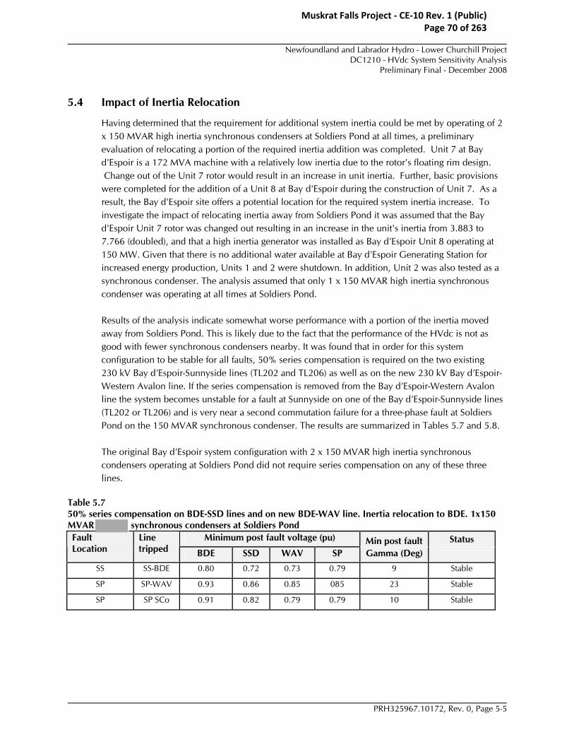
Newfoundland and Labrador Hydro - Lower Churchill Project
DC1210 - HVdc System Sensitivity AnalysisPreliminary Final - December 2008
PRH325967.10172, Rev. 0, Page 5-5
5.4 Impact of Inertia Relocation
Having determined that the requirement for additional system inertia could be met by operating of 2 x 150 MVAR high inertia synchronous condensers at Soldiers Pond at all times, a preliminary evaluation of relocating a portion of the required inertia addition was completed. Unit 7 at Bay d'Espoir is a 172 MVA machine with a relatively low inertia due to the rotor's floating rim design. Change out of the Unit 7 rotor would result in an increase in unit inertia. Further, basic provisions were completed for the addition of a Unit 8 at Bay d'Espoir during the construction of Unit 7. As a result, the Bay d'Espoir site offers a potential location for the required system inertia increase. To investigate the impact of relocating inertia away from Soldiers Pond it was assumed that the Bay d'Espoir Unit 7 rotor was changed out resulting in an increase in the unit's inertia from 3.883 to 7.766 (doubled), and that a high inertia generator was installed as Bay d’Espoir Unit 8 operating at 150 MW. Given that there is no additional water available at Bay d’Espoir Generating Station for increased energy production, Units 1 and 2 were shutdown. In addition, Unit 2 was also tested as a synchronous condenser. The analysis assumed that only 1 x 150 MVAR high inertia synchronous condenser was operating at all times at Soldiers Pond.
Results of the analysis indicate somewhat worse performance with a portion of the inertia moved away from Soldiers Pond. This is likely due to the fact that the performance of the HVdc is not as good with fewer synchronous condensers nearby. It was found that in order for this system configuration to be stable for all faults, 50% series compensation is required on the two existing 230 kV Bay d’Espoir-Sunnyside lines (TL202 and TL206) as well as on the new 230 kV Bay d’Espoir-Western Avalon line. If the series compensation is removed from the Bay d’Espoir-Western Avalon line the system becomes unstable for a fault at Sunnyside on one of the Bay d’Espoir-Sunnyside lines (TL202 or TL206) and is very near a second commutation failure for a three-phase fault at Soldiers Pond on the 150 MVAR synchronous condenser. The results are summarized in Tables 5.7 and 5.8.
The original Bay d’Espoir system configuration with 2 x 150 MVAR high inertia synchronous condensers operating at Soldiers Pond did not require series compensation on any of these three lines.
Table 5.7 50% series compensation on BDE-SSD lines and on new BDE-WAV line. Inertia relocation to BDE. 1x150 MVAR synchronous condensers at Soldiers Pond
Minimum post fault voltage (pu) Min post fault Status Fault Location
Line tripped BDE SSD WAV SP Gamma (Deg)
SS SS-BDE 0.80 0.72 0.73 0.79 9 Stable
SP SP-WAV 0.93 0.86 0.85 085 23 Stable
SP SP SCo 0.91 0.82 0.79 0.79 10 Stable
Muskrat Falls Project - CE-10 Rev. 1 (Public) Page 70 of 263

Newfoundland and Labrador Hydro - Lower Churchill Project
DC1210 - HVdc System Sensitivity AnalysisPreliminary Final - December 2008
PRH325967.10172, Rev. 0, Page 5-6
Table 5.8 No series compensation on new BDE-WAV line, 50% series compensation on BDE-SSD lines. Inertia relocation to BDE. 1x150 MVAR synchronous condensers at Soldiers Pond
Minimum post fault voltage (pu) Min post fault Status Fault Location
Line tripped BDE SSD WAV SP Gamma (Deg)
SS SS-BDE - - - - - Unstable
SP SP-WAV 0.93 0.86 0.85 0.85 23 Stable
SP SP SCo 0.90 0.80 0.78 0.78 7.5* Stable
*On the verge of a second commutation failure.
The 800 MW monopolar 10-minute 2.0 pu overload case was verified to ensure sufficient VAR support to maintain the steady state system voltages with only 1x150 MVAR synchronous condenser operating at Soldiers Pond. The Soldiers Pond synchronous condenser is producing maximum reactive power of 150 MVAR during the 10 minute 2.0 pu overload condition. It is unable to hold the voltage setpoint of 1.0284 pu as was used in all of the studies, however the voltage at Soldiers Pond is still maintained at 1.018 pu, with voltages at Sunnyside dropping to 1.005 pu and Bay d’Espoir to 1.0264 pu. All system voltages are within criteria, however, despite being slightly lower than in the normal system intact 800 MW bipolar case.
Muskrat Falls Project - CE-10 Rev. 1 (Public) Page 71 of 263

Newfoundland and Labrador Hydro - Lower Churchill Project
DC1210 - HVdc System Sensitivity AnalysisPreliminary Final - December 2008
PRH325967.10172, Rev. 0, Page 6-1
6. Conclusions If the intent is to design the HVdc infeed system such that its performance is similar to the existing system performance (i.e. does not survive the worst case fault), the requirements for synchronous condensers on the Island system are reduced. It must be noted that failure of the HVdc infeed system for the worst case fault is expected to result in system wide collapse as opposed to loss of approximately 500 MW in the existing system. The main issue in the Island system with the HVdc infeed is lack of inertia and resulting frequency decay due to faults which cause the HVdc infeed to fail commutation; the nearer the fault location to Bay d’Espoir generating station, the more power temporarily lost and the more severe the system frequency decay.
A new synchronous condenser model with a very high inertia constant (7.84) was tested. The high inertia machine showed significant improvement in system performance over the synchronous condenser models with a lower inertia constant (2.2) used in the original DC1020 studies.
It was found that without synchronous condensers at Pipers Hole, either an SVC at Sunnyside, or a new 230 kV circuit between Bay d’Espoir and Western Avalon will provide acceptable system performance for all contingencies except the three-phase fault at Bay d’Espoir. The results are highly dependent on the type of synchronous condenser that is modeled. Table 6.1 below summarizes the possible mitigating solutions for the Island system dynamic performance, ignoring the Bay d’Espoir three-phase fault.
Table 6.1 Possible Solutions to Eliminate Synchronous Condensers at Pipers Hole
Synch. Cond. Type SP Synch. Cond. In-service Sunnyside SVC BDE-WAV
230 kV line 50% compensation on
BDE-SSD lines? MIL- 2.2 inertia 2x300 MVAR 400 MVAR +
100 MVAR caps - Yes
MIL – 2.2 inertia 2x300 MVAR - Yes, with 50% compensation
Yes
– 7.84 inertia 1x300 MVAR 300 MVAR - Yes
– 7.84 inertia 2x150 MVAR 200 MVAR - Yes
– 7.84 inertia 2x150 MVAR - Yes No
The high inertia synchronous condensers would significantly reduce the size or number of synchronous condenser that are required to be installed at Soldiers Pond. In order to meet criteria for a fault at Sunnyside on one of the Bay d’Espoir-Sunnyside lines, a single 300 MVAR high inertia synchronous condenser is sufficient, along with a 300 (not 200 MVAR as indicated in Table 6.1 row three) MVAR SVC at Sunnyside or a new 230 kV circuit between Bay d’Espoir and Western Avalon. However, because loss of the Soldiers Pond synchronous condenser becomes the worst case contingency if only a single 300 MVAR unit is installed, it is recommended to have 2x150 MVAR high inertia synchronous condensers in-service at all times, which would translate to 3x150 MVAR installed to account for maintenance outages. The added benefit to a synchronous condenser rating of 150 MVAR is that it would match the Holyrood synchronous condenser ratings and their spare transformer.
Muskrat Falls Project - CE-10 Rev. 1 (Public) Page 72 of 263

Newfoundland and Labrador Hydro - Lower Churchill Project
DC1210 - HVdc System Sensitivity AnalysisPreliminary Final - December 2008
PRH325967.10172, Rev. 0, Page 6-2
Therefore from a technical system performance point of view, the best solution would be to have 2x150 MVAR high inertia synchronous condensers in-service at Soldiers Pond at all times, therefore installing 3x150 MVAR in order to account for maintenance outages. In addition to these 150 MVAR synchronous condensers, one of the following mitigation options is also required:
1. 200 MVAR SVC at Sunnyside and 50% series compensation on the two Bay d’Espoir-Sunnyside lines, or
2. 230 kV line Bay d’Espoir – Western Avalon, no series compensation on this new line or on the existing two Bay d’Espoir-Sunnyside lines
Both of these solutions provide sufficient steady state VAR support to maintain system steady state voltages during the 800 MW monopolar 10-minute 2.0 pu overload condition. Approximately 200 MVAR is required in steady state from the Soldiers Pond synchronous condensers to maintain the 1.0284 pu voltage setpoint that was used in the studies.
Because such good performance was obtained with the high inertia synchronous condensers, the three-phase Bay d’Espoir fault was re-visited. It was found that in order to design the system to survive a three-phase fault at Bay d’Espoir, the only option that recovered within criteria was a case with the new 230 kV circuit between Bay d’Espoir and Western Avalon. If this new circuit plus the two circuits between Bay d’Espoir and Sunnyside are 50% series compensated, AND if 2x300 MVAR high inertia synchronous condensers are in service at Soldiers Pond (which means 3x300 MVAR installed to account for maintenance outages), the system is able to recover within criteria from a three-phase fault at Bay d’Espoir.
A preliminary evaluation was performed to look at the impact of relocating a portion of the inertia from Soldiers Pond to Bay d’Espoir by changing out the rotor on Bay d’Espoir Unit 7 and by installing a high inertia 150 MVAR synchronous condenser as Bay d’Espoir Unit 8. The analysis was performed with only 1 x 150 MVAR high inertia synchronous condenser operating at Soldiers Pond instead of 2 x 150 MVAR. Despite the fact that the total system inertia is very similar between the two cases, the results indicate poorer performance of the Island system when the synchronous condensers are moved away from Soldiers Pond due to poorer performance of the HVdc infeed. This system configuration as studied would require the addition of the 230 kV circuit between Bay d’Espoir and Western Avalon with 50% series compensation as well as 50% series compensation on the two Bay d’Espoir – Sunnyside 230 kV lines. If even the series compensation from the new Bay d’Espoir – Western Avalon line is removed the system becomes unstable for a fault at Sunnyside on one of the Bay d’Espoir lines (TL202 or TL206), and in addition the HVdc infeed is on the verge of a second commutation failure for a three phase fault on the Soldiers Pond synchronous condenser.
Muskrat Falls Project - CE-10 Rev. 1 (Public) Page 73 of 263

Newfoundland and Labrador Hydro - Lower Churchill Project
DC1210 - HVdc System Sensitivity AnalysisPreliminary Final - December 2008
PRH325967.10172, Rev. 0, Page A-1
Appendix A 2x150 MVAR SCo at SP, 200 MVAR SVC at
Sunnyside, 50% series compensation on BDE-SSD lines, 3PF SSD-BDE
Muskrat Falls Project - CE-10 Rev. 1 (Public) Page 74 of 263

APPENDIX ALower Churchill ProjectSensitivity Analysis - Transient Stability
TransGrid Solutions Inc.
Page 13PF Sunnyside, clear Sunnyside-Bay d'Espoir 100 ms.Max Bay d'Espoir generation dispatch. Future peak load, no refinery, 50% series compensation on Bay d'Espoir-Sunnyside lines.
2x150 Synchronous Condensers @ Soldiers Pond, 200 MVAR SVC at Sunnyside.
PSS/E v30
time(sec) 0.00 0.50 1.00 1.50 2.00 2.50 3.00 3.50 4.00 4.50 5.00
0.00 0.20 0.40 0.60 0.80 1.00 1.20
puVac - 230 kV Bay d'Espoir
0.00
0.20 0.40
0.60
0.80 1.00
1.20
pu
Vac - 230 kV Sunnyside
0.00 0.20 0.40 0.60 0.80 1.00 1.20
pu
Vac - 230 kV Western Avalon
0.00
0.20 0.40
0.60
0.80 1.00
pu
Vac - 230 kV Soldiers Pond
0 10 20 30 40 50 60 70 80 90
100
deg
HVDC Gamma firing angle
0 20 40 60 80
100 120 140 160 180 200
MW
Power - Bay d'Espoir - Sunnyside line
-0.0100 -0.0080 -0.0060 -0.0040 -0.0020 0.0000 0.0020 0.0040 0.0060 0.0080 0.0100
pu
Frequency at Bay d'Espoir
Muskrat Falls Project - CE-10 Rev. 1 (Public) Page 75 of 263

Newfoundland and Labrador Hydro - Lower Churchill Project
DC1210 - HVdc System Sensitivity AnalysisPreliminary Final - December 2008
PRH325967.10172, Rev. 0, Page B-1
Appendix B 2x150 MVAR SCo at SP, new BDE-WAV line, no
series compensation on any lines, 3PF SSD-BDE
Muskrat Falls Project - CE-10 Rev. 1 (Public) Page 76 of 263

APPENDIX BLower Churchill ProjectSensitivity Analysis - Transient Stability
TransGrid Solutions Inc.
Page 13PF Sunnyside, clear Sunnyside-Bay d'Espoir 100 ms.Max Bay d'Espoir generation dispatch. Future peak load, no refinery, NO series compensation.
2x150 Synchronous Condensers @ Soldiers Pond, New 230 kV line from Bay d'Espoir-Western Avalon.
PSS/E v30
time(sec) 0.00 0.50 1.00 1.50 2.00 2.50 3.00 3.50 4.00 4.50 5.00
0.00 0.20 0.40 0.60 0.80 1.00 1.20
puVac - 230 kV Bay d'Espoir
0.00
0.20 0.40
0.60
0.80 1.00
1.20
pu
Vac - 230 kV Sunnyside
0.00 0.20 0.40 0.60 0.80 1.00 1.20
pu
Vac - 230 kV Western Avalon
0.00
0.20 0.40
0.60
0.80 1.00
pu
Vac - 230 kV Soldiers Pond
0 10 20 30 40 50 60 70 80 90
100
deg
HVDC Gamma firing angle
0 20 40 60 80
100 120 140 160 180 200
MW
Power - Bay d'Espoir - Sunnyside line
-0.0100 -0.0080 -0.0060 -0.0040 -0.0020 0.0000 0.0020 0.0040 0.0060 0.0080 0.0100
pu
Frequency at Bay d'Espoir
Muskrat Falls Project - CE-10 Rev. 1 (Public) Page 77 of 263

Newfoundland and Labrador Hydro - Lower Churchill Project
DC1210 - HVdc System Sensitivity AnalysisPreliminary Final - December 2008
PRH325967.10172, Rev. 0, Page C-1
Appendix C 2x300 MVAR SCo at SP, new BDE-WAV line, series compensation on BDE-WAV and both BDE-SSD lines, 3PF
BDE-SSD
Muskrat Falls Project - CE-10 Rev. 1 (Public) Page 78 of 263

APPENDIX CLower Churchill ProjectSensitivity Analysis - Transient Stability
TransGrid Solutions Inc.
Page 13PF Bay d'Espoir, clear Sunnyside-Bay d'Espoir 100 ms.Max Bay d'Espoir generation dispatch. Future peak load, no refinery, 50% series compensation on Bay d'Espoir-Sunnyside lines.
2x300 Synchronous Condensers @ Soldiers Pond, new 230 kV line Bay d'Espoir-Western Avalon, 50% series compensation.
PSS/E v30
time(sec) 0.00 0.50 1.00 1.50 2.00 2.50 3.00 3.50 4.00 4.50 5.00
0.00 0.20 0.40 0.60 0.80 1.00 1.20
puVac - 230 kV Bay d'Espoir
0.00
0.20 0.40
0.60
0.80 1.00
1.20
pu
Vac - 230 kV Sunnyside
0.00 0.20 0.40 0.60 0.80 1.00 1.20
pu
Vac - 230 kV Western Avalon
0.00
0.20 0.40
0.60
0.80 1.00
pu
Vac - 230 kV Soldiers Pond
0 10 20 30 40 50 60 70 80 90
100
deg
HVDC Gamma firing angle
0 20 40 60 80
100 120 140 160 180 200
MW
Power - Bay d'Espoir - Sunnyside line
-0.0100 -0.0080 -0.0060 -0.0040 -0.0020 0.0000 0.0020 0.0040 0.0060 0.0080 0.0100
pu
Frequency at Bay d'Espoir
Muskrat Falls Project - CE-10 Rev. 1 (Public) Page 79 of 263

Newfoundland and Labrador Hydro - Lower Churchill Project
DC1210 - HVdc System Sensitivity AnalysisPreliminary Final - December 2008
PRH325967.10172, Rev. 0, Page D-1
Appendix D Frequency plot for the case testing a special protection
scheme to split Avalon Peninsula for a three-phase fault at Bay d’Espoir. 2x150 MVAR SCo at SP, new
BDE-WAV line, 3PF BDE-SSD
Muskrat Falls Project - CE-10 Rev. 1 (Public) Page 80 of 263

APPENDIX DLower Churchill ProjectSensitivity Analysis - Transient Stability
TransGrid Solutions Inc.
Page 13PF Bay d'Espoir, clear Sunnyside-Bay d'Espoir 100 ms, Isolate Avalon peninsula.Max Bay d'Espoir generation dispatch. Future peak load, no refinery, NO series compensation.
2x150 Synchronous Condensers @ Soldiers Pond, new 230 kV line Bay d'Espoir-Western Avalon.
PSS/E v30
time(sec) 0.00 0.50 1.00 1.50 2.00 2.50 3.00 3.50 4.00 4.50 5.00
-0.050
-0.040
-0.030
-0.020
-0.010
0.000
0.010
0.020
0.030
0.040
0.050 pu
FREQ 2490
0.000
0.010
0.020
0.030
0.040
0.050
0.060
0.070
0.080
0.090
0.100
pu
Frequency at Bay d'Espoir
Muskrat Falls Project - CE-10 Rev. 1 (Public) Page 81 of 263

Nalcor Energy - Lower Churchill ProjectDC1210 - HVdc Sensitivity Studies Summary Report
Final Report - July 2010
PRH325967.10326, Rev. 0, Page B-1
Appendix B DC1210 PSSE Model Final Report
Muskrat Falls Project - CE-10 Rev. 1 (Public) Page 82 of 263

Engineering Support Services for
the Lower Churchill Project Newfoundland and Labrador Hydro
DC1210 – PSSE Model Final Report
May 21, 2009
Muskrat Falls Project - CE-10 Rev. 1 (Public) Page 83 of 263

Nalcor Energy - Lower Churchill Project
DC1210 - PSSE ModelFinal Report - May 21, 2009
PRH325967.10226, Rev. 0, Page i
Nalcor Energy Lower Churchill Project
DC1210 - PSSE Model
Final Report
Prepared by: May 20, 2009 Rebecca Brandt, P.Eng. Date Approvals Hatch Approved by: May 20, 2009 Pete Kuffel, P.Eng. Date Nalcor Energy Approved by: Date
Distribution List
Muskrat Falls Project - CE-10 Rev. 1 (Public) Page 84 of 263

Nalcor Energy - Lower Churchill Project
DC1210 - PSSE ModelFinal Report - May 21, 2009
PRH325967.10226, Rev. 0, Page i
Table of Contents
1. Introduction ......................................................................................................................................... 1-1
2. Summary .............................................................................................................................................. 2-1
3. Power Flow Test Case .......................................................................................................................... 3-1
4. Procedure and Results.......................................................................................................................... 4-1
5. User Instructions.................................................................................................................................. 5-1 Appendices Appendix A – Validation Testing Results
Muskrat Falls Project - CE-10 Rev. 1 (Public) Page 85 of 263

Nalcor Energy - Lower Churchill Project
DC1210 - PSSE ModelFinal Report - May 21, 2009
PRH325967.10226, Rev. 0, Page 1-1
1. Introduction The original WTO DC1020 transient stability analysis assumed a multi-terminal HVdc system with a 480 km cable connection between Newfoundland and New Brunswick across the Cabot Strait. A major task of the WTO was the development of a multi-terminal HVdc model for future PSSE studies. As part of WTO DC1210 Nalcor Energy – Lower Churchill Project requested that the PSSE model developed as part of DC1020 be modified to include a shorter cable between Newfoundland and Nova Scotia along with a new HVdc overhead transmission line from Nova Scotia to New Brunswick.
This report summarizes the work done to implement the requested modifications and presents the results of the validation testing performed.
Muskrat Falls Project - CE-10 Rev. 1 (Public) Page 86 of 263

Nalcor Energy - Lower Churchill Project
DC1210 - PSSE ModelFinal Report - May 21, 2009
PRH325967.10226, Rev. 0, Page 2-1
2. Summary The PSSE stability model of the three-terminal HVdc link for the Lower Churchill Project has been modified to represent a shorter DC cable section and longer DC overhead line section between the tap at Taylor’s Brook and the terminal at Salisbury. Specifically, the cable section between Newfoundland and Lingan, Nova Scotia is estimated at 180 km, and the new overhead line section from Lingan, Nova Scotia to Salisbury, New Brunswick is estimated at 475 km. The overhead line sections in Newfoundland from Taylor’s Brook to the Gulf of St. Lawrence crossing to Nova Scotia remain unchanged.
The PSSE multi-terminal HVdc model has been modified and validated to be capable of operating in bipolar or monopolar modes for the following HVdc configurations:
1. 3-terminal: Gull Island – rectifier, Soldiers Pond – inverter, Salisbury – inverter
2. 2-terminal: Soldiers Pond – rectifier, Salisbury – inverter
3. 2-terminal: Salisbury – rectifier, Soldiers Pond - inverter
The validation testing for the monopolar configuration was performed using the 3-terminal HVdc configuration.
Muskrat Falls Project - CE-10 Rev. 1 (Public) Page 87 of 263

Nalcor Energy - Lower Churchill Project
DC1210 - PSSE ModelFinal Report - May 21, 2009
PRH325967.10226, Rev. 0, Page 3-1
3. Power Flow Test Case For the 3-terminal HVdc configuration, the PSSE model validation was performed using an equivalent test system representing power flow case BC1-DC1: rated bipolar operation with Gull Island as rectifier and Soldiers Pond and Salisbury as inverters (3-terminal).
The validation testing case was performed in an equivalent test system using the following system strengths:
• Gull Island – 4654 MVA <87 deg
• Soldiers Pond – 3305 MVA <74.1 deg
• Salisbury – 3949 MVA <76 deg
The above systems strengths represent a weak configuration at Gull Island, one 150 MVAR synchronous condenser in-service at Soldiers Pond (Xd’’ = 0.165 pu) and one 125 MVAR synchronous condenser in-service at Salisbury (Xd’’ = 0.165 pu) based on information from previously completed studies.
For the 2-terminal HVdc configurations, the PSCAD model had previously been set up using equivalent test systems, however the PSSE models that were readily available for these power flow configurations had been set up to use an equivalent source at the Salisbury terminal and the reduced version of the Newfoundland system PSSE model for the Soldiers Pond terminal. This difference in test systems results in slightly different AC voltage response for the 2-terminal test cases, however the response (especially of the HVdc quantities) very closely matches the PSCAD model and therefore still provides validation of the PSSE model.
Muskrat Falls Project - CE-10 Rev. 1 (Public) Page 88 of 263

Nalcor Energy - Lower Churchill Project
DC1210 - PSSE ModelFinal Report - May 21, 2009
PRH325967.10226, Rev. 0, Page 4-1
4. Procedure and Results The PSCAD model was first updated and the DC controls were re-tuned. These changes were implemented inside the PSSE model. Validation testing was performed by comparing the results of the PSCAD and PSSE models for a solid and remote three-phase fault at each of the DC terminals for the 3-terminal case, and for solid faults only for the 2-terminal cases.
Validation testing results are provided in the Appendix. The PSSE model compares well with the PSCAD model results.
Muskrat Falls Project - CE-10 Rev. 1 (Public) Page 89 of 263

Nalcor Energy - Lower Churchill Project
DC1210 - PSSE ModelFinal Report - May 21, 2009
PRH325967.10226, Rev. 0, Page 5-1
5. User Instructions The user need not change any input parameters to the PSSE dynamics model, other than to ensure CON(J+5) DC_CONFIG is set to the appropriate value:
‘1’ - 3-terminal: Gull Island – rectifier, Soldiers Pond – inverter, Salisbury – inverter
‘2’ - 2-terminal: Soldiers Pond – rectifier, Salisbury – inverter
‘3’ - 2-terminal: Salisbury – rectifier, Soldiers Pond - inverter
Other than CON(J+5) the original documentation for the PSSE model still applies in terms of model use instructions (Chapter 7 of DC1020 report: Multi-Terminal HVdc Link PSSE Stability Model). All dynamics model changes were internal within the PSSE model code. The updated compiled model is provided (CLCPDC-short_cable-full_version.OBJ).
The user should change the DC resistance value in the PSSE loadflow model of the DC line section from the DC tap (dc bus 2) to the NB DC terminal (dc bus 4) to be 9.451 ohms instead of 8.433 ohms (a read change raw data file is provided as an example for the 3-terminal configuration – LCP-short_cable.raw). The IPLAN program used to calculate the steady state DC operating points for the multi-terminal DC loadflow model also uses this DC resistance value and it had to be changed internally. An updated IPLAN (LCP-short_cable.ipl, LCP-short_cable.irf) is also provided.
Muskrat Falls Project - CE-10 Rev. 1 (Public) Page 90 of 263

Nalcor Energy - Lower Churchill Project
DC1210 - PSSE ModelFinal Report - May 21, 2009
PRH325967.10226, Rev. 0
Appendix A Validation Testing Results
Muskrat Falls Project - CE-10 Rev. 1 (Public) Page 91 of 263

TransGrid SolutionsLower Churchill ProjectMulti-Terminal HVDC LinkPSSE Transient Stability Model Validation - Shorter Cable Distance
Three-Phase Solid Fault (0%) - Gull Island 230 kV BusGull Island 1600 MW Rectifier, Soldiers Pond 800 MW Inverter, Salisbury 800 MW Inverter
System Equivalent Model - Minimum Short Circuit Levels
PSSE v30.3PSCAD v4.2.1
Gull Island - Rectifier
Time(s... 0.00 0.25 0.50 0.75 1.00 1.25 1.50 1.75 2.00
0.00
0.20
0.40
0.60
0.80
1.00
1.20
1.40 pu
PSCAD AC Voltage Gull Island 230 kV PSSE AC Voltage Gull Island 230 kV
0.0 0.2k0.4k0.6k0.8k1.0k1.2k1.4k1.6k1.8k2.0k
MW
PSCAD DC Power PSSE DC Power
0.0 0.1k0.2k0.3k0.4k0.5k0.6k0.7k0.8k0.9k1.0k
PSCAD Q HVDC Converter
MVA
R
PSSE Q HVDC Converter
0.00
0.25
0.50
0.75
1.00
1.25
1.50
1.75
2.00
pu
PSCAD DC Voltage PSSE DC Voltage
0.00
0.25
0.50
0.75
1.00
1.25
1.50
1.75
2.00
pu
PSCAD DC Current PSSE DC Current
Muskrat Falls Project - CE-10 Rev. 1 (Public) Page 92 of 263

TransGrid SolutionsLower Churchill ProjectMulti-Terminal HVDC LinkPSSE Transient Stability Model Validation - Shorter Cable Distance
Three-Phase Solid Fault (0%) - Gull Island 230 kV BusGull Island 1600 MW Rectifier, Soldiers Pond 800 MW Inverter, Salisbury 800 MW Inverter
System Equivalent Model - Minimum Short Circuit Levels
PSSE v30.3PSCAD v4.2.1
Soldiers Pond - Inverter
Time(s... 0.00 0.25 0.50 0.75 1.00 1.25 1.50 1.75 2.00
0.00
0.20
0.40
0.60
0.80
1.00
1.20
1.40 pu
PSCAD AC Voltage Soldiers Pond 230 kV PSSE AC Voltage Soldiers Pond 230 kV
0.0 0.1k0.2k0.3k0.4k0.5k0.6k0.7k0.8k0.9k1.0k
MW
PSCAD DC Power PSSE DC Poewr
0 50
100 150 200 250 300 350 400 450 500
MVA
R
PSCAD Q HVDC Converter PSSE Q HVDC Converter
0.00
0.25
0.50
0.75
1.00
1.25
1.50
1.75
2.00
pu
PSCAD DC Voltage PSSE DC Voltage
0.0
1.0
2.0
3.0
4.0
5.0
6.0
7.0
8.0
pu
PSCAD DC Current PSSE DC Current
Muskrat Falls Project - CE-10 Rev. 1 (Public) Page 93 of 263

TransGrid SolutionsLower Churchill ProjectMulti-Terminal HVDC LinkPSSE Transient Stability Model Validation - Shorter Cable Distance
Three-Phase Solid Fault (0%) - Gull Island 230 kV BusGull Island 1600 MW Rectifier, Soldiers Pond 800 MW Inverter, Salisbury 800 MW Inverter
System Equivalent Model - Minimum Short Circuit Levels
PSSE v30.3PSCAD v4.2.1
Salisbury - Inverter
Time(s... 0.00 0.25 0.50 0.75 1.00 1.25 1.50 1.75 2.00
0.00
0.20
0.40
0.60
0.80
1.00
1.20
1.40 pu
PSCAD AC Voltage Salisbury 345 kV PSSE AC Voltage Salisbury 345 kV
0.0 0.1k0.2k0.3k0.4k0.5k0.6k0.7k0.8k0.9k1.0k
MW
PSCAD DC Power PSSE DC Power
0 50
100 150 200 250 300 350 400 450 500
MVA
R
PSCAD Q HVDC Converter PSSE Q HVDC Converter
0.00
0.25
0.50
0.75
1.00
1.25
1.50
1.75
2.00
pu
PSCAD DC Voltage PSSE DC Voltage
0.0
1.0
2.0
3.0
4.0
5.0
6.0
7.0
8.0
pu
PSCAD DC Current PSSE DC Current
Muskrat Falls Project - CE-10 Rev. 1 (Public) Page 94 of 263
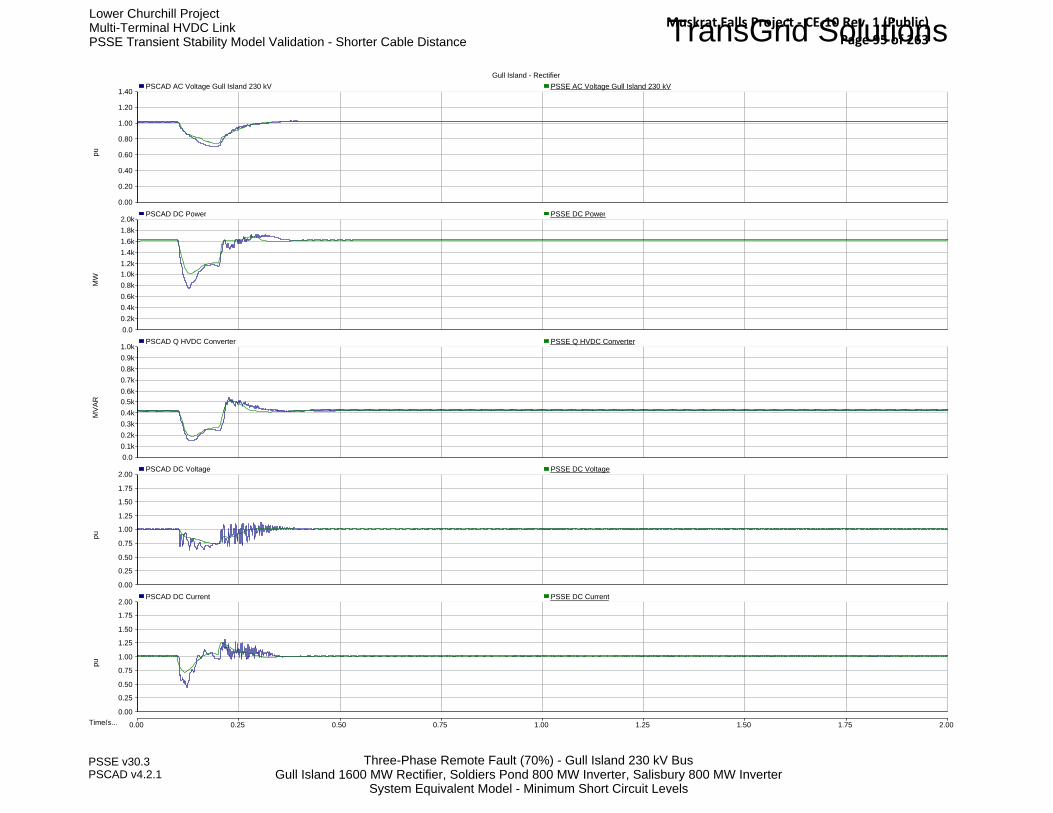
TransGrid SolutionsLower Churchill ProjectMulti-Terminal HVDC LinkPSSE Transient Stability Model Validation - Shorter Cable Distance
Three-Phase Remote Fault (70%) - Gull Island 230 kV BusGull Island 1600 MW Rectifier, Soldiers Pond 800 MW Inverter, Salisbury 800 MW Inverter
System Equivalent Model - Minimum Short Circuit Levels
PSSE v30.3PSCAD v4.2.1
Gull Island - Rectifier
Time(s... 0.00 0.25 0.50 0.75 1.00 1.25 1.50 1.75 2.00
0.00
0.20
0.40
0.60
0.80
1.00
1.20
1.40 pu
PSCAD AC Voltage Gull Island 230 kV PSSE AC Voltage Gull Island 230 kV
0.0 0.2k0.4k0.6k0.8k1.0k1.2k1.4k1.6k1.8k2.0k
MW
PSCAD DC Power PSSE DC Power
0.0 0.1k0.2k0.3k0.4k0.5k0.6k0.7k0.8k0.9k1.0k
PSCAD Q HVDC Converter
MVA
R
PSSE Q HVDC Converter
0.00
0.25
0.50
0.75
1.00
1.25
1.50
1.75
2.00
pu
PSCAD DC Voltage PSSE DC Voltage
0.00
0.25
0.50
0.75
1.00
1.25
1.50
1.75
2.00
pu
PSCAD DC Current PSSE DC Current
Muskrat Falls Project - CE-10 Rev. 1 (Public) Page 95 of 263

TransGrid SolutionsLower Churchill ProjectMulti-Terminal HVDC LinkPSSE Transient Stability Model Validation - Shorter Cable Distance
Three-Phase Remote Fault (70%) - Gull Island 230 kV BusGull Island 1600 MW Rectifier, Soldiers Pond 800 MW Inverter, Salisbury 800 MW Inverter
System Equivalent Model - Minimum Short Circuit Levels
PSSE v30.3PSCAD v4.2.1
Soldiers Pond - Inverter
Time(s... 0.00 0.25 0.50 0.75 1.00 1.25 1.50 1.75 2.00
0.00
0.20
0.40
0.60
0.80
1.00
1.20
1.40 pu
PSCAD AC Voltage Soldiers Pond 230 kV PSSE AC Voltage Soldiers Pond 230 kV
0.0 0.1k0.2k0.3k0.4k0.5k0.6k0.7k0.8k0.9k1.0k
MW
PSCAD DC Power PSSE DC Poewr
0 50
100 150 200 250 300 350 400 450 500
MVA
R
PSCAD Q HVDC Converter PSSE Q HVDC Converter
0.00
0.25
0.50
0.75
1.00
1.25
1.50
1.75
2.00
pu
PSCAD DC Voltage PSSE DC Voltage
0.0
1.0
2.0
3.0
4.0
5.0
6.0
7.0
8.0
pu
PSCAD DC Current PSSE DC Current
Muskrat Falls Project - CE-10 Rev. 1 (Public) Page 96 of 263

TransGrid SolutionsLower Churchill ProjectMulti-Terminal HVDC LinkPSSE Transient Stability Model Validation - Shorter Cable Distance
Three-Phase Remote Fault (70%) - Gull Island 230 kV BusGull Island 1600 MW Rectifier, Soldiers Pond 800 MW Inverter, Salisbury 800 MW Inverter
System Equivalent Model - Minimum Short Circuit Levels
PSSE v30.3PSCAD v4.2.1
Salisbury - Inverter
Time(s... 0.00 0.25 0.50 0.75 1.00 1.25 1.50 1.75 2.00
0.00
0.20
0.40
0.60
0.80
1.00
1.20
1.40 pu
PSCAD AC Voltage Salisbury 345 kV PSSE AC Voltage Salisbury 345 kV
0.0 0.1k0.2k0.3k0.4k0.5k0.6k0.7k0.8k0.9k1.0k
MW
PSCAD DC Power PSSE DC Power
0 50
100 150 200 250 300 350 400 450 500
MVA
R
PSCAD Q HVDC Converter PSSE Q HVDC Converter
0.00
0.25
0.50
0.75
1.00
1.25
1.50
1.75
2.00
pu
PSCAD DC Voltage PSSE DC Voltage
0.0
1.0
2.0
3.0
4.0
5.0
6.0
7.0
8.0
pu
PSCAD DC Current PSSE DC Current
Muskrat Falls Project - CE-10 Rev. 1 (Public) Page 97 of 263

TransGrid SolutionsLower Churchill ProjectMulti-Terminal HVDC LinkPSSE Transient Stability Model Validation - Shorter Cable Distance
Three-Phase Solid Fault (0%) - Soldiers Pond 230 kV BusGull Island 1600 MW Rectifier, Soldiers Pond 800 MW Inverter, Salisbury 800 MW Inverter
System Equivalent Model - Minimum Short Circuit Levels
PSSE v30.3PSCAD v4.2.1
Gull Island - Rectifier
Time(s... 0.00 0.25 0.50 0.75 1.00 1.25 1.50 1.75 2.00
0.00
0.20
0.40
0.60
0.80
1.00
1.20
1.40 pu
PSCAD AC Voltage Gull Island 230 kV PSSE AC Voltage Gull Island 230 kV
0.0 0.2k0.4k0.6k0.8k1.0k1.2k1.4k1.6k1.8k2.0k
MW
PSCAD DC Power PSSE DC Power
0.0 0.1k0.2k0.3k0.4k0.5k0.6k0.7k0.8k0.9k1.0k
PSCAD Q HVDC Converter
MVA
R
PSSE Q HVDC Converter
0.00
0.25
0.50
0.75
1.00
1.25
1.50
1.75
2.00
pu
PSCAD DC Voltage PSSE DC Voltage
0.00
0.25
0.50
0.75
1.00
1.25
1.50
1.75
2.00
pu
PSCAD DC Current PSSE DC Current
Muskrat Falls Project - CE-10 Rev. 1 (Public) Page 98 of 263

TransGrid SolutionsLower Churchill ProjectMulti-Terminal HVDC LinkPSSE Transient Stability Model Validation - Shorter Cable Distance
Three-Phase Solid Fault (0%) - Soldiers Pond 230 kV BusGull Island 1600 MW Rectifier, Soldiers Pond 800 MW Inverter, Salisbury 800 MW Inverter
System Equivalent Model - Minimum Short Circuit Levels
PSSE v30.3PSCAD v4.2.1
Soldiers Pond - Inverter
Time(s... 0.00 0.25 0.50 0.75 1.00 1.25 1.50 1.75 2.00
0.00
0.20
0.40
0.60
0.80
1.00
1.20
1.40 pu
PSCAD AC Voltage Soldiers Pond 230 kV PSSE AC Voltage Soldiers Pond 230 kV
0.0 0.1k0.2k0.3k0.4k0.5k0.6k0.7k0.8k0.9k1.0k
MW
PSCAD DC Power PSSE DC Poewr
0 50
100 150 200 250 300 350 400 450 500
MVA
R
PSCAD Q HVDC Converter PSSE Q HVDC Converter
0.00
0.25
0.50
0.75
1.00
1.25
1.50
1.75
2.00
pu
PSCAD DC Voltage PSSE DC Voltage
0.0
1.0
2.0
3.0
4.0
5.0
6.0
7.0
8.0
pu
PSCAD DC Current PSSE DC Current
Muskrat Falls Project - CE-10 Rev. 1 (Public) Page 99 of 263

TransGrid SolutionsLower Churchill ProjectMulti-Terminal HVDC LinkPSSE Transient Stability Model Validation - Shorter Cable Distance
Three-Phase Solid Fault (0%) - Soldiers Pond 230 kV BusGull Island 1600 MW Rectifier, Soldiers Pond 800 MW Inverter, Salisbury 800 MW Inverter
System Equivalent Model - Minimum Short Circuit Levels
PSSE v30.3PSCAD v4.2.1
Salisbury - Inverter
Time(s... 0.00 0.25 0.50 0.75 1.00 1.25 1.50 1.75 2.00
0.00
0.20
0.40
0.60
0.80
1.00
1.20
1.40 pu
PSCAD AC Voltage Salisbury 345 kV PSSE AC Voltage Salisbury 345 kV
0.0 0.1k0.2k0.3k0.4k0.5k0.6k0.7k0.8k0.9k1.0k
MW
PSCAD DC Power PSSE DC Power
0 50
100 150 200 250 300 350 400 450 500
MVA
R
PSCAD Q HVDC Converter PSSE Q HVDC Converter
0.00
0.25
0.50
0.75
1.00
1.25
1.50
1.75
2.00
pu
PSCAD DC Voltage PSSE DC Voltage
0.0
1.0
2.0
3.0
4.0
5.0
6.0
7.0
8.0
pu
PSCAD DC Current PSSE DC Current
Muskrat Falls Project - CE-10 Rev. 1 (Public) Page 100 of 263

TransGrid SolutionsLower Churchill ProjectMulti-Terminal HVDC LinkPSSE Transient Stability Model Validation - Shorter Cable Distance
Three-Phase Remote Fault (70%) - Soldiers Pond 230 kV BusGull Island 1600 MW Rectifier, Soldiers Pond 800 MW Inverter, Salisbury 800 MW Inverter
System Equivalent Model - Minimum Short Circuit Levels
PSSE v30.3PSCAD v4.2.1
Gull Island - Rectifier
Time(s... 0.00 0.25 0.50 0.75 1.00 1.25 1.50 1.75 2.00
0.00
0.20
0.40
0.60
0.80
1.00
1.20
1.40 pu
PSCAD AC Voltage Gull Island 230 kV PSSE AC Voltage Gull Island 230 kV
0.0 0.2k0.4k0.6k0.8k1.0k1.2k1.4k1.6k1.8k2.0k
MW
PSCAD DC Power PSSE DC Power
0.0 0.1k0.2k0.3k0.4k0.5k0.6k0.7k0.8k0.9k1.0k
PSCAD Q HVDC Converter
MVA
R
PSSE Q HVDC Converter
0.00
0.25
0.50
0.75
1.00
1.25
1.50
1.75
2.00
pu
PSCAD DC Voltage PSSE DC Voltage
0.00
0.25
0.50
0.75
1.00
1.25
1.50
1.75
2.00
pu
PSCAD DC Current PSSE DC Current
Muskrat Falls Project - CE-10 Rev. 1 (Public) Page 101 of 263

TransGrid SolutionsLower Churchill ProjectMulti-Terminal HVDC LinkPSSE Transient Stability Model Validation - Shorter Cable Distance
Three-Phase Remote Fault (70%) - Soldiers Pond 230 kV BusGull Island 1600 MW Rectifier, Soldiers Pond 800 MW Inverter, Salisbury 800 MW Inverter
System Equivalent Model - Minimum Short Circuit Levels
PSSE v30.3PSCAD v4.2.1
Soldiers Pond - Inverter
Time(s... 0.00 0.25 0.50 0.75 1.00 1.25 1.50 1.75 2.00
0.00
0.20
0.40
0.60
0.80
1.00
1.20
1.40 pu
PSCAD AC Voltage Soldiers Pond 230 kV PSSE AC Voltage Soldiers Pond 230 kV
0.0 0.1k0.2k0.3k0.4k0.5k0.6k0.7k0.8k0.9k1.0k
MW
PSCAD DC Power PSSE DC Poewr
0 50
100 150 200 250 300 350 400 450 500
MVA
R
PSCAD Q HVDC Converter PSSE Q HVDC Converter
0.00
0.25
0.50
0.75
1.00
1.25
1.50
1.75
2.00
pu
PSCAD DC Voltage PSSE DC Voltage
0.0
1.0
2.0
3.0
4.0
5.0
6.0
7.0
8.0
pu
PSCAD DC Current PSSE DC Current
Muskrat Falls Project - CE-10 Rev. 1 (Public) Page 102 of 263

TransGrid SolutionsLower Churchill ProjectMulti-Terminal HVDC LinkPSSE Transient Stability Model Validation - Shorter Cable Distance
Three-Phase Remote Fault (70%) - Soldiers Pond 230 kV BusGull Island 1600 MW Rectifier, Soldiers Pond 800 MW Inverter, Salisbury 800 MW Inverter
System Equivalent Model - Minimum Short Circuit Levels
PSSE v30.3PSCAD v4.2.1
Salisbury - Inverter
Time(s... 0.00 0.25 0.50 0.75 1.00 1.25 1.50 1.75 2.00
0.00
0.20
0.40
0.60
0.80
1.00
1.20
1.40 pu
PSCAD AC Voltage Salisbury 345 kV PSSE AC Voltage Salisbury 345 kV
0.0 0.1k0.2k0.3k0.4k0.5k0.6k0.7k0.8k0.9k1.0k
MW
PSCAD DC Power PSSE DC Power
0 50
100 150 200 250 300 350 400 450 500
MVA
R
PSCAD Q HVDC Converter PSSE Q HVDC Converter
0.00
0.25
0.50
0.75
1.00
1.25
1.50
1.75
2.00
pu
PSCAD DC Voltage PSSE DC Voltage
0.0
1.0
2.0
3.0
4.0
5.0
6.0
7.0
8.0
pu
PSCAD DC Current PSSE DC Current
Muskrat Falls Project - CE-10 Rev. 1 (Public) Page 103 of 263

TransGrid SolutionsLower Churchill ProjectMulti-Terminal HVDC LinkPSSE Transient Stability Model Validation - Shorter Cable Distance
Three-Phase Solid Fault (0%) - Salisbury 345 kV BusGull Island 1600 MW Rectifier, Soldiers Pond 800 MW Inverter, Salisbury 800 MW Inverter
System Equivalent Model - Minimum Short Circuit Levels
PSSE v30.3PSCAD v4.2.1
Gull Island - Rectifier
Time(s... 0.00 0.25 0.50 0.75 1.00 1.25 1.50 1.75 2.00
0.00
0.20
0.40
0.60
0.80
1.00
1.20
1.40 pu
PSCAD AC Voltage Gull Island 230 kV PSSE AC Voltage Gull Island 230 kV
0.0 0.2k0.4k0.6k0.8k1.0k1.2k1.4k1.6k1.8k2.0k
MW
PSCAD DC Power PSSE DC Power
0.0 0.1k0.2k0.3k0.4k0.5k0.6k0.7k0.8k0.9k1.0k
PSCAD Q HVDC Converter
MVA
R
PSSE Q HVDC Converter
0.00
0.25
0.50
0.75
1.00
1.25
1.50
1.75
2.00
pu
PSCAD DC Voltage PSSE DC Voltage
0.00
0.25
0.50
0.75
1.00
1.25
1.50
1.75
2.00
pu
PSCAD DC Current PSSE DC Current
Muskrat Falls Project - CE-10 Rev. 1 (Public) Page 104 of 263

TransGrid SolutionsLower Churchill ProjectMulti-Terminal HVDC LinkPSSE Transient Stability Model Validation - Shorter Cable Distance
Three-Phase Solid Fault (0%) - Salisbury 345 kV BusGull Island 1600 MW Rectifier, Soldiers Pond 800 MW Inverter, Salisbury 800 MW Inverter
System Equivalent Model - Minimum Short Circuit Levels
PSSE v30.3PSCAD v4.2.1
Soldiers Pond - Inverter
Time(s... 0.00 0.25 0.50 0.75 1.00 1.25 1.50 1.75 2.00
0.00
0.20
0.40
0.60
0.80
1.00
1.20
1.40 pu
PSCAD AC Voltage Soldiers Pond 230 kV PSSE AC Voltage Soldiers Pond 230 kV
0.0 0.1k0.2k0.3k0.4k0.5k0.6k0.7k0.8k0.9k1.0k
MW
PSCAD DC Power PSSE DC Poewr
0 50
100 150 200 250 300 350 400 450 500
MVA
R
PSCAD Q HVDC Converter PSSE Q HVDC Converter
0.00
0.25
0.50
0.75
1.00
1.25
1.50
1.75
2.00
pu
PSCAD DC Voltage PSSE DC Voltage
0.0
1.0
2.0
3.0
4.0
5.0
6.0
7.0
8.0
pu
PSCAD DC Current PSSE DC Current
Muskrat Falls Project - CE-10 Rev. 1 (Public) Page 105 of 263

TransGrid SolutionsLower Churchill ProjectMulti-Terminal HVDC LinkPSSE Transient Stability Model Validation - Shorter Cable Distance
Three-Phase Solid Fault (0%) - Salisbury 345 kV BusGull Island 1600 MW Rectifier, Soldiers Pond 800 MW Inverter, Salisbury 800 MW Inverter
System Equivalent Model - Minimum Short Circuit Levels
PSSE v30.3PSCAD v4.2.1
Salisbury - Inverter
Time(s... 0.00 0.25 0.50 0.75 1.00 1.25 1.50 1.75 2.00
0.00
0.20
0.40
0.60
0.80
1.00
1.20
1.40 pu
PSCAD AC Voltage Salisbury 345 kV PSSE AC Voltage Salisbury 345 kV
0.0 0.1k0.2k0.3k0.4k0.5k0.6k0.7k0.8k0.9k1.0k
MW
PSCAD DC Power PSSE DC Power
0 50
100 150 200 250 300 350 400 450 500
MVA
R
PSCAD Q HVDC Converter PSSE Q HVDC Converter
0.00
0.25
0.50
0.75
1.00
1.25
1.50
1.75
2.00
pu
PSCAD DC Voltage PSSE DC Voltage
0.0
1.0
2.0
3.0
4.0
5.0
6.0
7.0
8.0
pu
PSCAD DC Current PSSE DC Current
Muskrat Falls Project - CE-10 Rev. 1 (Public) Page 106 of 263

TransGrid SolutionsLower Churchill ProjectMulti-Terminal HVDC LinkPSSE Transient Stability Model Validation - Shorter Cable Distance
Three-Phase Remote Fault (70%) - Salisbury 345 kV BusGull Island 1600 MW Rectifier, Soldiers Pond 800 MW Inverter, Salisbury 800 MW Inverter
System Equivalent Model - Minimum Short Circuit Levels
PSSE v30.3PSCAD v4.2.1
Gull Island - Rectifier
Time(s... 0.00 0.25 0.50 0.75 1.00 1.25 1.50 1.75 2.00
0.00
0.20
0.40
0.60
0.80
1.00
1.20
1.40 pu
PSCAD AC Voltage Gull Island 230 kV PSSE AC Voltage Gull Island 230 kV
0.0 0.2k0.4k0.6k0.8k1.0k1.2k1.4k1.6k1.8k2.0k
MW
PSCAD DC Power PSSE DC Power
0.0 0.1k0.2k0.3k0.4k0.5k0.6k0.7k0.8k0.9k1.0k
PSCAD Q HVDC Converter
MVA
R
PSSE Q HVDC Converter
0.00
0.25
0.50
0.75
1.00
1.25
1.50
1.75
2.00
pu
PSCAD DC Voltage PSSE DC Voltage
0.00
0.25
0.50
0.75
1.00
1.25
1.50
1.75
2.00
pu
PSCAD DC Current PSSE DC Current
Muskrat Falls Project - CE-10 Rev. 1 (Public) Page 107 of 263

TransGrid SolutionsLower Churchill ProjectMulti-Terminal HVDC LinkPSSE Transient Stability Model Validation - Shorter Cable Distance
Three-Phase Remote Fault (70%) - Salisbury 345 kV BusGull Island 1600 MW Rectifier, Soldiers Pond 800 MW Inverter, Salisbury 800 MW Inverter
System Equivalent Model - Minimum Short Circuit Levels
PSSE v30.3PSCAD v4.2.1
Soldiers Pond - Inverter
Time(s... 0.00 0.25 0.50 0.75 1.00 1.25 1.50 1.75 2.00
0.00
0.20
0.40
0.60
0.80
1.00
1.20
1.40 pu
PSCAD AC Voltage Soldiers Pond 230 kV PSSE AC Voltage Soldiers Pond 230 kV
0.0 0.1k0.2k0.3k0.4k0.5k0.6k0.7k0.8k0.9k1.0k
MW
PSCAD DC Power PSSE DC Poewr
0 50
100 150 200 250 300 350 400 450 500
MVA
R
PSCAD Q HVDC Converter PSSE Q HVDC Converter
0.00
0.25
0.50
0.75
1.00
1.25
1.50
1.75
2.00
pu
PSCAD DC Voltage PSSE DC Voltage
0.0
1.0
2.0
3.0
4.0
5.0
6.0
7.0
8.0
pu
PSCAD DC Current PSSE DC Current
Muskrat Falls Project - CE-10 Rev. 1 (Public) Page 108 of 263

TransGrid SolutionsLower Churchill ProjectMulti-Terminal HVDC LinkPSSE Transient Stability Model Validation - Shorter Cable Distance
Three-Phase Remote Fault (70%) - Salisbury 345 kV BusGull Island 1600 MW Rectifier, Soldiers Pond 800 MW Inverter, Salisbury 800 MW Inverter
System Equivalent Model - Minimum Short Circuit Levels
PSSE v30.3PSCAD v4.2.1
Salisbury - Inverter
Time(s... 0.00 0.25 0.50 0.75 1.00 1.25 1.50 1.75 2.00
0.00
0.20
0.40
0.60
0.80
1.00
1.20
1.40 pu
PSCAD AC Voltage Salisbury 345 kV PSSE AC Voltage Salisbury 345 kV
0.0 0.1k0.2k0.3k0.4k0.5k0.6k0.7k0.8k0.9k1.0k
MW
PSCAD DC Power PSSE DC Power
0 50
100 150 200 250 300 350 400 450 500
MVA
R
PSCAD Q HVDC Converter PSSE Q HVDC Converter
0.00
0.25
0.50
0.75
1.00
1.25
1.50
1.75
2.00
pu
PSCAD DC Voltage PSSE DC Voltage
0.0
1.0
2.0
3.0
4.0
5.0
6.0
7.0
8.0
pu
PSCAD DC Current PSSE DC Current
Muskrat Falls Project - CE-10 Rev. 1 (Public) Page 109 of 263

TransGrid SolutionsLower Churchill ProjectMulti-Terminal HVDC LinkPSSE Transient Stability Model Validation - Shorter Cable Distance
Three-Phase Solid Fault (0%) - Gull Island 230 kV BusMonopolar: Gull Island 1046 MW Rectifier, Soldiers Pond 572 MW Inverter, Salisbury 400 MW Inverter
System Equivalent Model - Minimum Short Circuit Levels
PSSE v30.3PSCAD v4.2.1
Gull Island - Rectifier
Time(s... 0.00 0.25 0.50 0.75 1.00 1.25 1.50 1.75 2.00
0.00
0.20
0.40
0.60
0.80
1.00
1.20
1.40 pu
PSCAD AC Voltage Gull Island 230 kV PSSE AC Voltage Gull Island 230 kV
0.0 0.2k0.4k0.6k0.8k1.0k1.2k1.4k1.6k1.8k2.0k
MW
PSCAD DC Power PSSE DC Power
0.0 0.1k0.2k0.3k0.4k0.5k0.6k0.7k0.8k0.9k1.0k
PSCAD Q HVDC Converter
MVA
R
PSSE Q HVDC Converter
0.00
0.25
0.50
0.75
1.00
1.25
1.50
1.75
2.00
pu
PSCAD DC Voltage PSSE DC Voltage
0.00
0.25
0.50
0.75
1.00
1.25
1.50
1.75
2.00
pu
PSCAD DC Current PSSE DC Current
Muskrat Falls Project - CE-10 Rev. 1 (Public) Page 110 of 263

TransGrid SolutionsLower Churchill ProjectMulti-Terminal HVDC LinkPSSE Transient Stability Model Validation - Shorter Cable Distance
Three-Phase Solid Fault (0%) - Gull Island 230 kV BusMonopolar: Gull Island 1046 MW Rectifier, Soldiers Pond 572 MW Inverter, Salisbury 400 MW Inverter
System Equivalent Model - Minimum Short Circuit Levels
PSSE v30.3PSCAD v4.2.1
Soldiers Pond - Inverter
Time(s... 0.00 0.25 0.50 0.75 1.00 1.25 1.50 1.75 2.00
0.00
0.20
0.40
0.60
0.80
1.00
1.20
1.40 pu
PSCAD AC Voltage Soldiers Pond 230 kV PSSE AC Voltage Soldiers Pond 230 kV
0.0 0.1k0.2k0.3k0.4k0.5k0.6k0.7k0.8k0.9k1.0k
MW
PSCAD DC Power PSSE DC Poewr
0 50
100 150 200 250 300 350 400 450 500
MVA
R
PSCAD Q HVDC Converter PSSE Q HVDC Converter
0.00
0.25
0.50
0.75
1.00
1.25
1.50
1.75
2.00
pu
PSCAD DC Voltage PSSE DC Voltage
0.0
1.0
2.0
3.0
4.0
5.0
6.0
7.0
8.0
pu
PSCAD DC Current PSSE DC Current
Muskrat Falls Project - CE-10 Rev. 1 (Public) Page 111 of 263

TransGrid SolutionsLower Churchill ProjectMulti-Terminal HVDC LinkPSSE Transient Stability Model Validation - Shorter Cable Distance
Three-Phase Solid Fault (0%) - Gull Island 230 kV BusMonopolar: Gull Island 1046 MW Rectifier, Soldiers Pond 572 MW Inverter, Salisbury 400 MW Inverter
System Equivalent Model - Minimum Short Circuit Levels
PSSE v30.3PSCAD v4.2.1
Salisbury - Inverter
Time(s... 0.00 0.25 0.50 0.75 1.00 1.25 1.50 1.75 2.00
0.00
0.20
0.40
0.60
0.80
1.00
1.20
1.40 pu
PSCAD AC Voltage Salisbury 345 kV PSSE AC Voltage Salisbury 345 kV
0.0 0.1k0.2k0.3k0.4k0.5k0.6k0.7k0.8k0.9k1.0k
MW
PSCAD DC Power PSSE DC Power
0 50
100 150 200 250 300 350 400 450 500
MVA
R
PSCAD Q HVDC Converter PSSE Q HVDC Converter
0.00
0.25
0.50
0.75
1.00
1.25
1.50
1.75
2.00
pu
PSCAD DC Voltage PSSE DC Voltage
0.0
1.0
2.0
3.0
4.0
5.0
6.0
7.0
8.0
pu
PSCAD DC Current PSSE DC Current
Muskrat Falls Project - CE-10 Rev. 1 (Public) Page 112 of 263
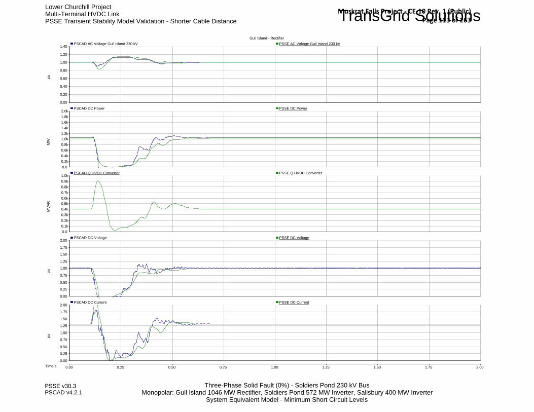
TransGrid SolutionsLower Churchill ProjectMulti-Terminal HVDC LinkPSSE Transient Stability Model Validation - Shorter Cable Distance
Three-Phase Solid Fault (0%) - Soldiers Pond 230 kV BusMonopolar: Gull Island 1046 MW Rectifier, Soldiers Pond 572 MW Inverter, Salisbury 400 MW Inverter
System Equivalent Model - Minimum Short Circuit Levels
PSSE v30.3PSCAD v4.2.1
Gull Island - Rectifier
Time(s... 0.00 0.25 0.50 0.75 1.00 1.25 1.50 1.75 2.00
0.00
0.20
0.40
0.60
0.80
1.00
1.20
1.40 pu
PSCAD AC Voltage Gull Island 230 kV PSSE AC Voltage Gull Island 230 kV
0.0 0.2k0.4k0.6k0.8k1.0k1.2k1.4k1.6k1.8k2.0k
MW
PSCAD DC Power PSSE DC Power
0.0 0.1k0.2k0.3k0.4k0.5k0.6k0.7k0.8k0.9k1.0k
PSCAD Q HVDC Converter
MVA
R
PSSE Q HVDC Converter
0.00
0.25
0.50
0.75
1.00
1.25
1.50
1.75
2.00
pu
PSCAD DC Voltage PSSE DC Voltage
0.00
0.25
0.50
0.75
1.00
1.25
1.50
1.75
2.00
pu
PSCAD DC Current PSSE DC Current
Muskrat Falls Project - CE-10 Rev. 1 (Public) Page 113 of 263

TransGrid SolutionsLower Churchill ProjectMulti-Terminal HVDC LinkPSSE Transient Stability Model Validation - Shorter Cable Distance
Three-Phase Solid Fault (0%) - Soldiers Pond 230 kV BusMonopolar: Gull Island 1046 MW Rectifier, Soldiers Pond 572 MW Inverter, Salisbury 400 MW Inverter
System Equivalent Model - Minimum Short Circuit Levels
PSSE v30.3PSCAD v4.2.1
Soldiers Pond - Inverter
Time(s... 0.00 0.25 0.50 0.75 1.00 1.25 1.50 1.75 2.00
0.00
0.20
0.40
0.60
0.80
1.00
1.20
1.40 pu
PSCAD AC Voltage Soldiers Pond 230 kV PSSE AC Voltage Soldiers Pond 230 kV
0.0 0.1k0.2k0.3k0.4k0.5k0.6k0.7k0.8k0.9k1.0k
MW
PSCAD DC Power PSSE DC Poewr
0 50
100 150 200 250 300 350 400 450 500
MVA
R
PSCAD Q HVDC Converter PSSE Q HVDC Converter
0.00
0.25
0.50
0.75
1.00
1.25
1.50
1.75
2.00
pu
PSCAD DC Voltage PSSE DC Voltage
0.0
1.0
2.0
3.0
4.0
5.0
6.0
7.0
8.0
pu
PSCAD DC Current PSSE DC Current
Muskrat Falls Project - CE-10 Rev. 1 (Public) Page 114 of 263

TransGrid SolutionsLower Churchill ProjectMulti-Terminal HVDC LinkPSSE Transient Stability Model Validation - Shorter Cable Distance
Three-Phase Solid Fault (0%) - Soldiers Pond 230 kV BusMonopolar: Gull Island 1046 MW Rectifier, Soldiers Pond 572 MW Inverter, Salisbury 400 MW Inverter
System Equivalent Model - Minimum Short Circuit Levels
PSSE v30.3PSCAD v4.2.1
Salisbury - Inverter
Time(s... 0.00 0.25 0.50 0.75 1.00 1.25 1.50 1.75 2.00
0.00
0.20
0.40
0.60
0.80
1.00
1.20
1.40 pu
PSCAD AC Voltage Salisbury 345 kV PSSE AC Voltage Salisbury 345 kV
0.0 0.1k0.2k0.3k0.4k0.5k0.6k0.7k0.8k0.9k1.0k
MW
PSCAD DC Power PSSE DC Power
0 50
100 150 200 250 300 350 400 450 500
MVA
R
PSCAD Q HVDC Converter PSSE Q HVDC Converter
0.00
0.25
0.50
0.75
1.00
1.25
1.50
1.75
2.00
pu
PSCAD DC Voltage PSSE DC Voltage
0.0
1.0
2.0
3.0
4.0
5.0
6.0
7.0
8.0
pu
PSCAD DC Current PSSE DC Current
Muskrat Falls Project - CE-10 Rev. 1 (Public) Page 115 of 263

TransGrid SolutionsLower Churchill ProjectMulti-Terminal HVDC LinkPSSE Transient Stability Model Validation - Shorter Cable Distance
Three-Phase Solid Fault (0%) - Salisbury 345 kV BusMonopolar: Gull Island 1046 MW Rectifier, Soldiers Pond 572 MW Inverter, Salisbury 400 MW Inverter
System Equivalent Model - Minimum Short Circuit Levels
PSSE v30.3PSCAD v4.2.1
Gull Island - Rectifier
Time(s... 0.00 0.25 0.50 0.75 1.00 1.25 1.50 1.75 2.00
0.00
0.20
0.40
0.60
0.80
1.00
1.20
1.40 pu
PSCAD AC Voltage Gull Island 230 kV PSSE AC Voltage Gull Island 230 kV
0.0 0.2k0.4k0.6k0.8k1.0k1.2k1.4k1.6k1.8k2.0k
MW
PSCAD DC Power PSSE DC Power
0.0 0.1k0.2k0.3k0.4k0.5k0.6k0.7k0.8k0.9k1.0k
MVA
R
PSSE Q HVDC Converter
0.00
0.25
0.50
0.75
1.00
1.25
1.50
1.75
2.00
pu
PSCAD DC Voltage PSSE DC Voltage
0.00
0.25
0.50
0.75
1.00
1.25
1.50
1.75
2.00
pu
PSCAD DC Current PSSE DC Current
Muskrat Falls Project - CE-10 Rev. 1 (Public) Page 116 of 263

TransGrid SolutionsLower Churchill ProjectMulti-Terminal HVDC LinkPSSE Transient Stability Model Validation - Shorter Cable Distance
Three-Phase Solid Fault (0%) - Salisbury 345 kV BusMonopolar: Gull Island 1046 MW Rectifier, Soldiers Pond 572 MW Inverter, Salisbury 400 MW Inverter
System Equivalent Model - Minimum Short Circuit Levels
PSSE v30.3PSCAD v4.2.1
Soldiers Pond - Inverter
Time(s... 0.00 0.25 0.50 0.75 1.00 1.25 1.50 1.75 2.00
0.00
0.20
0.40
0.60
0.80
1.00
1.20
1.40 pu
PSCAD AC Voltage Soldiers Pond 230 kV PSSE AC Voltage Soldiers Pond 230 kV
0.0 0.1k0.2k0.3k0.4k0.5k0.6k0.7k0.8k0.9k1.0k
MW
PSCAD DC Power PSSE DC Poewr
0 50
100 150 200 250 300 350 400 450 500
MVA
R
PSCAD Q HVDC Converter PSSE Q HVDC Converter
0.00
0.25
0.50
0.75
1.00
1.25
1.50
1.75
2.00
pu
PSCAD DC Voltage PSSE DC Voltage
0.0
1.0
2.0
3.0
4.0
5.0
6.0
7.0
8.0
pu
PSCAD DC Current PSSE DC Current
Muskrat Falls Project - CE-10 Rev. 1 (Public) Page 117 of 263
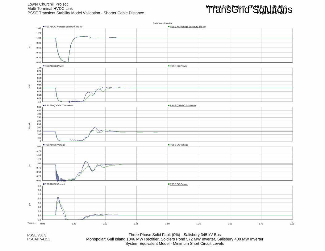
TransGrid SolutionsLower Churchill ProjectMulti-Terminal HVDC LinkPSSE Transient Stability Model Validation - Shorter Cable Distance
Three-Phase Solid Fault (0%) - Salisbury 345 kV BusMonopolar: Gull Island 1046 MW Rectifier, Soldiers Pond 572 MW Inverter, Salisbury 400 MW Inverter
System Equivalent Model - Minimum Short Circuit Levels
PSSE v30.3PSCAD v4.2.1
Salisbury - Inverter
Time(s... 0.00 0.25 0.50 0.75 1.00 1.25 1.50 1.75 2.00
0.00
0.20
0.40
0.60
0.80
1.00
1.20
1.40 pu
PSCAD AC Voltage Salisbury 345 kV PSSE AC Voltage Salisbury 345 kV
0.0 0.1k0.2k0.3k0.4k0.5k0.6k0.7k0.8k0.9k1.0k
MW
PSCAD DC Power PSSE DC Power
0 50
100 150 200 250 300 350 400 450 500
MVA
R
PSCAD Q HVDC Converter PSSE Q HVDC Converter
0.00
0.25
0.50
0.75
1.00
1.25
1.50
1.75
2.00
pu
PSCAD DC Voltage PSSE DC Voltage
0.0
1.0
2.0
3.0
4.0
5.0
6.0
7.0
8.0
pu
PSCAD DC Current PSSE DC Current
Muskrat Falls Project - CE-10 Rev. 1 (Public) Page 118 of 263

TransGrid SolutionsLower Churchill ProjectMulti-Terminal HVDC LinkPSSE Transient Stability Model Validation - Shorter Cable Distance
Three-Phase Solid Fault (0%) - Soldiers Pond 230 kV BusTwo-Terminal: Gull Island OFF, Soldiers Pond 175 MW Rectifier, Salisbury 175 MW Inverter
System Equivalent Model PSCAD - Reduced System Model PSSE
PSSE v30.3PSCAD v4.2.1
Soldiers Pond - Rectifier
Time(s... 0.00 0.25 0.50 0.75 1.00 1.25 1.50 1.75 2.00
0.00
0.20
0.40
0.60
0.80
1.00
1.20
1.40 pu
PSCAD AC Voltage Soldiers Pond 230 kV PSSE AC Voltage Soldiers Pond 230 kV
0.0 0.1k0.2k0.3k0.4k0.5k0.6k0.7k0.8k0.9k1.0k
MW
PSCAD DC Power PSSE DC Poewr
0 50
100 150 200 250 300 350 400 450 500
MVA
R
PSCAD Q HVDC Converter PSSE Q HVDC Converter
0.00
0.25
0.50
0.75
1.00
1.25
1.50
1.75
2.00
pu
PSCAD DC Voltage PSSE DC Voltage
0.0
1.0
2.0
3.0
4.0
5.0
6.0
7.0
8.0
pu
PSCAD DC Current PSSE DC Current
Muskrat Falls Project - CE-10 Rev. 1 (Public) Page 119 of 263

TransGrid SolutionsLower Churchill ProjectMulti-Terminal HVDC LinkPSSE Transient Stability Model Validation - Shorter Cable Distance
Three-Phase Solid Fault (0%) - Soldiers Pond 230 kV BusTwo-Terminal: Gull Island OFF, Soldiers Pond 175 MW Rectifier, Salisbury 175 MW Inverter
System Equivalent Model PSCAD - Reduced System Model PSSE
PSSE v30.3PSCAD v4.2.1
Salisbury - Inverter
Time(s... 0.00 0.25 0.50 0.75 1.00 1.25 1.50 1.75 2.00
0.00
0.20
0.40
0.60
0.80
1.00
1.20
1.40 pu
PSCAD AC Voltage Salisbury 345 kV PSSE AC Voltage Salisbury 345 kV
0.0 0.1k0.2k0.3k0.4k0.5k0.6k0.7k0.8k0.9k1.0k
MW
PSCAD DC Power PSSE DC Power
0 50
100 150 200 250 300 350 400 450 500
MVA
R
PSCAD Q HVDC Converter PSSE Q HVDC Converter
0.00
0.25
0.50
0.75
1.00
1.25
1.50
1.75
2.00
pu
PSCAD DC Voltage PSSE DC Voltage
0.0
1.0
2.0
3.0
4.0
5.0
6.0
7.0
8.0
pu
PSCAD DC Current PSSE DC Current
Muskrat Falls Project - CE-10 Rev. 1 (Public) Page 120 of 263

TransGrid SolutionsLower Churchill ProjectMulti-Terminal HVDC LinkPSSE Transient Stability Model Validation - Shorter Cable Distance
Three-Phase Solid Fault (0%) - Salisbury 345 kV BusTwo-Terminal: Gull Island OFF, Soldiers Pond 175 MW Rectifier, Salisbury 175 MW Inverter
System Equivalent Model PSCAD - Reduced System Model PSSE
PSSE v30.3PSCAD v4.2.1
Soldiers Pond - Rectifier
Time(s... 0.00 0.25 0.50 0.75 1.00 1.25 1.50 1.75 2.00
0.00
0.20
0.40
0.60
0.80
1.00
1.20
1.40 pu
PSCAD AC Voltage Soldiers Pond 230 kV PSSE AC Voltage Soldiers Pond 230 kV
0.0 0.1k0.2k0.3k0.4k0.5k0.6k0.7k0.8k0.9k1.0k
MW
PSCAD DC Power PSSE DC Poewr
0 50
100 150 200 250 300 350 400 450 500
MVA
R
PSCAD Q HVDC Converter PSSE Q HVDC Converter
0.00
0.25
0.50
0.75
1.00
1.25
1.50
1.75
2.00
pu
PSCAD DC Voltage PSSE DC Voltage
0.0
1.0
2.0
3.0
4.0
5.0
6.0
7.0
8.0
pu
PSCAD DC Current PSSE DC Current
Muskrat Falls Project - CE-10 Rev. 1 (Public) Page 121 of 263

TransGrid SolutionsLower Churchill ProjectMulti-Terminal HVDC LinkPSSE Transient Stability Model Validation - Shorter Cable Distance
Three-Phase Solid Fault (0%) - Salisbury 345 kV BusTwo-Terminal: Gull Island OFF, Soldiers Pond 175 MW Rectifier, Salisbury 175 MW Inverter
System Equivalent Model PSCAD - Reduced System Model PSSE
PSSE v30.3PSCAD v4.2.1
Salisbury - Inverter
Time(s... 0.00 0.25 0.50 0.75 1.00 1.25 1.50 1.75 2.00
0.00
0.20
0.40
0.60
0.80
1.00
1.20
1.40 pu
PSCAD AC Voltage Salisbury 345 kV PSSE AC Voltage Salisbury 345 kV
0.0 0.1k0.2k0.3k0.4k0.5k0.6k0.7k0.8k0.9k1.0k
MW
PSCAD DC Power PSSE DC Power
0 50
100 150 200 250 300 350 400 450 500
MVA
R
PSCAD Q HVDC Converter PSSE Q HVDC Converter
0.00
0.25
0.50
0.75
1.00
1.25
1.50
1.75
2.00
pu
PSCAD DC Voltage PSSE DC Voltage
0.0
1.0
2.0
3.0
4.0
5.0
6.0
7.0
8.0
pu
PSCAD DC Current PSSE DC Current
Muskrat Falls Project - CE-10 Rev. 1 (Public) Page 122 of 263

TransGrid SolutionsLower Churchill ProjectMulti-Terminal HVDC LinkPSSE Transient Stability Model Validation - Shorter Cable Distance
Three-Phase Solid Fault (0%) - Soldiers Pond 230 kV BusTwo-Terminal: Gull Island OFF, Soldiers Pond 800 MW Inverter, Salisbury 800 MW Rectifier
System Equivalent Model PSCAD - Reduced System Model PSSE
PSSE v30.3PSCAD v4.2.1
Soldiers Pond - Inverter
Time(s... 0.00 0.25 0.50 0.75 1.00 1.25 1.50 1.75 2.00
0.00
0.20
0.40
0.60
0.80
1.00
1.20
1.40 pu
PSCAD AC Voltage Soldiers Pond 230 kV PSSE AC Voltage Soldiers Pond 230 kV
0.0 0.1k0.2k0.3k0.4k0.5k0.6k0.7k0.8k0.9k1.0k
MW
PSCAD DC Power PSSE DC Poewr
0 50
100 150 200 250 300 350 400 450 500
MVA
R
PSCAD Q HVDC Converter PSSE Q HVDC Converter
0.00
0.25
0.50
0.75
1.00
1.25
1.50
1.75
2.00
pu
PSCAD DC Voltage PSSE DC Voltage
0.0
1.0
2.0
3.0
4.0
5.0
6.0
7.0
8.0
pu
PSCAD DC Current PSSE DC Current
Muskrat Falls Project - CE-10 Rev. 1 (Public) Page 123 of 263

TransGrid SolutionsLower Churchill ProjectMulti-Terminal HVDC LinkPSSE Transient Stability Model Validation - Shorter Cable Distance
Three-Phase Solid Fault (0%) - Soldiers Pond 230 kV BusTwo-Terminal: Gull Island OFF, Soldiers Pond 800 MW Inverter, Salisbury 800 MW Rectifier
System Equivalent Model PSCAD - Reduced System Model PSSE
PSSE v30.3PSCAD v4.2.1
Salisbury - Rectifier
Time(s... 0.00 0.25 0.50 0.75 1.00 1.25 1.50 1.75 2.00
0.00
0.20
0.40
0.60
0.80
1.00
1.20
1.40 pu
PSCAD AC Voltage Salisbury 345 kV PSSE AC Voltage Salisbury 345 kV
0.0 0.1k0.2k0.3k0.4k0.5k0.6k0.7k0.8k0.9k1.0k
MW
PSCAD DC Power PSSE DC Power
0.0 0.1k0.2k0.3k0.4k0.5k0.6k0.7k0.8k0.9k1.0k
MVA
R
PSCAD Q HVDC Converter PSSE Q HVDC Converter
0.00
0.25
0.50
0.75
1.00
1.25
1.50
1.75
2.00
pu
PSCAD DC Voltage PSSE DC Voltage
0.0
1.0
2.0
3.0
4.0
5.0
6.0
7.0
8.0
pu
PSCAD DC Current PSSE DC Current
Muskrat Falls Project - CE-10 Rev. 1 (Public) Page 124 of 263

TransGrid SolutionsLower Churchill ProjectMulti-Terminal HVDC LinkPSSE Transient Stability Model Validation - Shorter Cable Distance
Three-Phase Solid Fault (0%) - Salisbury 345 kV BusTwo-Terminal: Gull Island OFF, Soldiers Pond 800 MW Inverter, Salisbury 800 MW Rectifier
System Equivalent Model PSCAD - Reduced System Model PSSE
PSSE v30.3PSCAD v4.2.1
Soldiers Pond - Inverter
Time(s... 0.00 0.25 0.50 0.75 1.00 1.25 1.50 1.75 2.00
0.00
0.20
0.40
0.60
0.80
1.00
1.20
1.40 pu
PSCAD AC Voltage Soldiers Pond 230 kV PSSE AC Voltage Soldiers Pond 230 kV
0.0 0.1k0.2k0.3k0.4k0.5k0.6k0.7k0.8k0.9k1.0k
MW
PSCAD DC Power PSSE DC Poewr
0 50
100 150 200 250 300 350 400 450 500
MVA
R
PSCAD Q HVDC Converter PSSE Q HVDC Converter
0.00
0.25
0.50
0.75
1.00
1.25
1.50
1.75
2.00
pu
PSCAD DC Voltage PSSE DC Voltage
0.0
1.0
2.0
3.0
4.0
5.0
6.0
7.0
8.0
pu
PSCAD DC Current PSSE DC Current
Muskrat Falls Project - CE-10 Rev. 1 (Public) Page 125 of 263
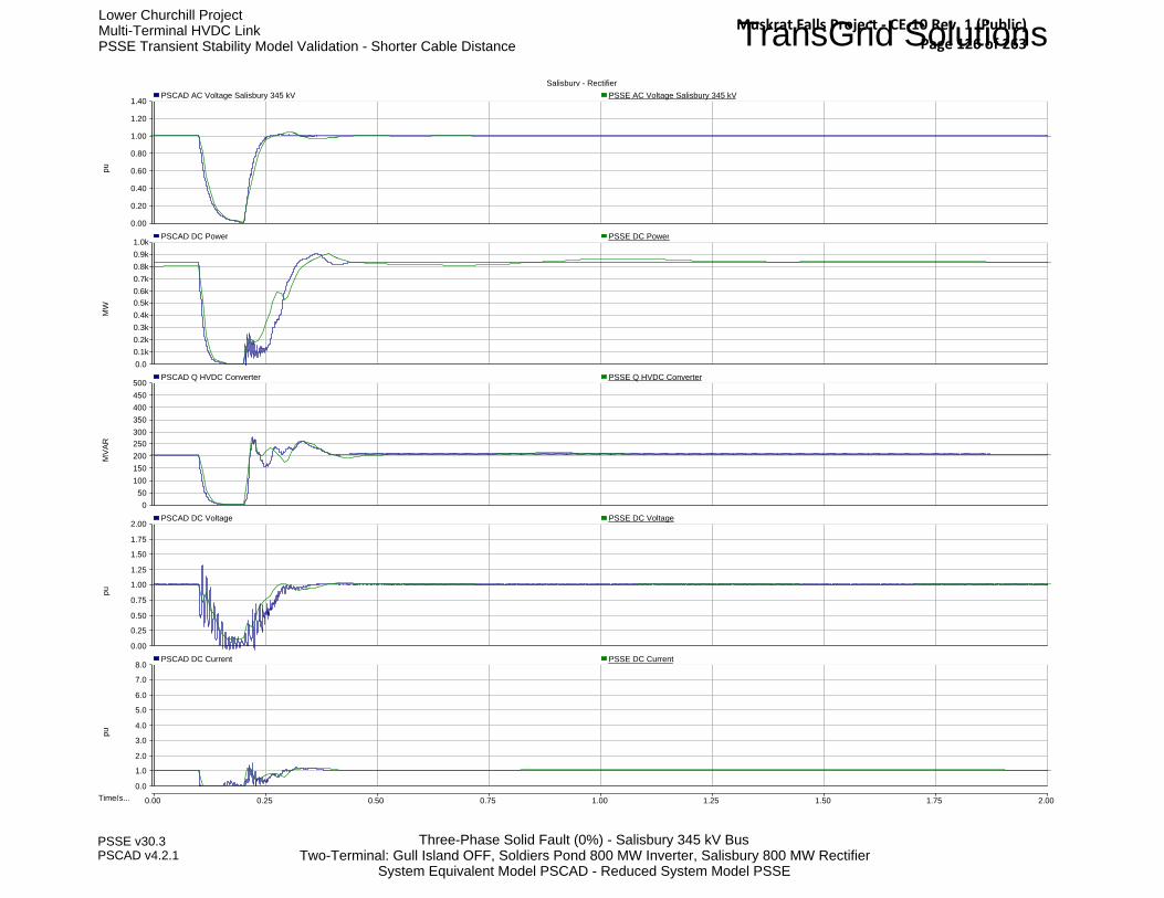
TransGrid SolutionsLower Churchill ProjectMulti-Terminal HVDC LinkPSSE Transient Stability Model Validation - Shorter Cable Distance
Three-Phase Solid Fault (0%) - Salisbury 345 kV BusTwo-Terminal: Gull Island OFF, Soldiers Pond 800 MW Inverter, Salisbury 800 MW Rectifier
System Equivalent Model PSCAD - Reduced System Model PSSE
PSSE v30.3PSCAD v4.2.1
Salisbury - Rectifier
Time(s... 0.00 0.25 0.50 0.75 1.00 1.25 1.50 1.75 2.00
0.00
0.20
0.40
0.60
0.80
1.00
1.20
1.40 pu
PSCAD AC Voltage Salisbury 345 kV PSSE AC Voltage Salisbury 345 kV
0.0 0.1k0.2k0.3k0.4k0.5k0.6k0.7k0.8k0.9k1.0k
MW
PSCAD DC Power PSSE DC Power
0 50
100 150 200 250 300 350 400 450 500
MVA
R
PSCAD Q HVDC Converter PSSE Q HVDC Converter
0.00
0.25
0.50
0.75
1.00
1.25
1.50
1.75
2.00
pu
PSCAD DC Voltage PSSE DC Voltage
0.0
1.0
2.0
3.0
4.0
5.0
6.0
7.0
8.0
pu
PSCAD DC Current PSSE DC Current
Muskrat Falls Project - CE-10 Rev. 1 (Public) Page 126 of 263

Nalcor Energy - Lower Churchill ProjectDC1210 - HVdc Sensitivity Studies Summary Report
Final Report - July 2010
PRH325967.10326, Rev. 0, Page C-1
Appendix C DC1210 VSC Risk Assessment Final Report
Muskrat Falls Project - CE-10 Rev. 1 (Public) Page 127 of 263

Muskrat Falls Project - CE-10 Rev. 1 (Public) Page 128 of 263

Newfoundland and Labrador Hydro - Lower Churchill ProjectDC1210 - VSC Risk Assessment
Final Report - January 2009
PRH325967.10172, Rev. 0, Page i
Table of Contents
List of Tables List of Figures Executive Summary
1. Introduction ......................................................................................................................................... 1-1
1.1 The Current State-of-the-Art of the VSC Technology .................................................................... 1-1 1.2 Operating Experience of VSC HVdc Stations ............................................................................... 1-2 1.3 Characteristics of VSC Converters ............................................................................................... 1-2
1.3.1 Two-Level Converter ......................................................................................................... 1-2 1.3.2 Three-Level Converter ....................................................................................................... 1-2 1.3.3 Multi-Module Converter .................................................................................................... 1-3
1.4 Comparison Between the Features of the VSC and the LCC......................................................... 1-4 1.5 Semiconductor Devices for VSC Applications ............................................................................. 1-6 1.6 Future of VSC Technology in HVdc............................................................................................. 1-6
2. Application of VSC in Multi-Terminal HVdc Systems........................................................................... 2-1
2.1 Multi-terminal configurations ...................................................................................................... 2-1
3. Description of the Lower Churchill HVdc Link .................................................................................... 3-1
4. Application of VSC in the Lower Churchill Project .............................................................................. 4-1
4.1 Basic Requirements..................................................................................................................... 4-1 4.2 Comparison with the Basic Requirements ................................................................................... 4-1
4.2.1 Bipolar Configuration ........................................................................................................ 4-1 4.2.2 DC Voltage of 450 kV ....................................................................................................... 4-1 4.2.3 The Station Rating at Gull Island........................................................................................ 4-1 4.2.4 The Station Rating at Soldiers Pond ................................................................................... 4-2 4.2.5 The Station Rating at Salisbury........................................................................................... 4-2 4.2.6 Power Reversal.................................................................................................................. 4-2 4.2.7 The Requirements for Synchronous Condensers for the Project ......................................... 4-2
4.3 Preliminary Simulation Study using VSC technology ................................................................... 4-4 4.3.1 Power Flow Case............................................................................................................... 4-4 4.3.2 VSC model in PSSE ........................................................................................................... 4-4 4.3.3 Contingencies ................................................................................................................... 4-5 4.3.4 Simulation Results ............................................................................................................. 4-6 4.3.5 Conclusions and Recommendations .................................................................................. 4-7
5. Conclusions.......................................................................................................................................... 5-1
6. Recommendations................................................................................................................................ 6-1
Muskrat Falls Project - CE-10 Rev. 1 (Public) Page 129 of 263
Newfoundland and Labrador Hydro - Lower Churchill ProjectDC1210 - VSC Risk Assessment
Final Report - January 2009
PRH325967.10172, Rev. 0, Page ii
List of Tables Number Title Table 1.1 VSC Based HVdc Systems Currently in Operation or Under Construction Table 1.2 Comparison between LCC based and VSC based HVdc Systems Table 4.1 Contingencies Table 4.2 Minimum Transient Undervoltages and System Stability Following Fault Clearing
Muskrat Falls Project - CE-10 Rev. 1 (Public) Page 130 of 263

Newfoundland and Labrador Hydro - Lower Churchill ProjectDC1210 - VSC Risk Assessment
Final Report - January 2009
PRH325967.10172, Rev. 0, Page iii
List of Figures Number Title Figure 1.1 Two-Level Converter Figure 1.2 Multi-Module Converter Figure 2.1 A Three-Terminal HVdc Configuration Figure 2.2 A VSC Based Multi-Terminal HVdc System Figure 2.3 Hybrid Multi-Terminal Configuration Figure 3.1 Lower Churchill HVdc System Terminal Locations Figure 4.1 VSC Converter with ac and dc Breakers
Muskrat Falls Project - CE-10 Rev. 1 (Public) Page 131 of 263

Newfoundland and Labrador Hydro - Lower Churchill ProjectDC1210 - VSC Risk Assessment
Final Report - January 2009
PRH325967.10172, Rev. 0, Page iv
Executive Summary
The purpose of this technical note is to present a high level evaluation of the application of a Voltage Source Converter (VSC) for the Lower Churchill HVdc transmission project.
In order to perform such an evaluation it is important to:
• Examine the status of the art of the VSC technology mainly as it applies to HVdc transmission.
• Examine the characteristics of the VSC.
• Examine the future developments in HVdc.
The evaluation involved obtaining the most up to date data from the suppliers regarding the ratings and availability of these ratings for commercial use. This was followed by comparing this information with the technical requirements of the HVdc project.
This high level evaluation concluded the following:
• The rating at Gull Island can be better realized using a conventional line commutated converter (LCC).
• The rating at Soldiers Pond can be achieved using a VSC converter.
• The rating at Salisbury can be achieved using a VSC converter.
• The HVdc cable will still require a mass impregnated cable.
• Results of preliminary transient stability simulations showed an overall improvement in system performance for all ac and dc faults that were studied with fewer synchronous condensers than required for the LCC technology.
The following recommendations are made:
• The application of VSC technology for the Lower Churchill Project should be considered; however, a performance study should be performed.
• Based on promising results seen from preliminary transient stability simulations, it is recommended to perform a more complete performance evaluation of VSC technology for the Soldiers Pond terminal.
Muskrat Falls Project - CE-10 Rev. 1 (Public) Page 132 of 263

Newfoundland and Labrador Hydro - Lower Churchill ProjectDC1210 - VSC Risk Assessment
Final Report - January 2009
PRH325967.10172, Rev. 0, Page 1-1
1. Introduction The purpose of this technical note is to present a high level evaluation of the application of a Voltage Source Converter (VSC) for the Lower Churchill HVdc transmission project. In order to perform such an evaluation it is important to:
• Examine the state-of-the-art of the VSC technology mainly as it applies to HVdc transmission.
• Examine the characteristics of the VSC.
• Examine the future developments in HVdc.
1.1 The Current State-of-the-Art of the VSC Technology
The VSC technology for HVdc power transmission applications is advancing quickly, from the start of a very moderate rating of 3 MW in 1997 which was demonstrated in the Hellsjőn project to the present rating of 400 MW in Transbay Cable Project to be in service in 2010. Currently HVdc using VSC technology can be at a rating of 1100 MW and +/- 320 kV with an overhead line. The current projection indicates that a full bipole at +/- 640 kV dc and 2200 MW is achievable.
Commercially the VSC technology is marketed by two of the leading suppliers of HVdc under two trade names:
• HVdc Light.
• HVdc Plus.
In the beginning, the application of VSC in HVdc was always tied to its connection to a HVdc cable, because in a VSC converter, during a dc fault, currents from the ac side feed through the bi-directional converter valves into the dc fault and cannot be cleared until the main ac breaker is tripped, unlike conventional LCC HVdc in which the ac side does not contribute to the dc fault due to the uni-directional valves. This means that during a dc fault on a VSC, the whole converter must be tripped in order to clear the fault, which means that automatic re-starting is not an option. Since cable applications do not usually offer a restart, as a fault on the cable is almost always a permanent fault, this limitation was not an issue for the VSC.
The idea here is that because a VSC does not control fault currents for faults occurring on the dc side it was always promoted as a complete solution with cables.
Since the VSC maintains a constant dc voltage, regardless of direction, reversal of power direction in a VSC HVdc system does not require the polarity reversal of the dc voltage, and so the use of a cheaper, cost effective Cross Linked Polyethylene (XLPE) cable in conjunction with VSC is wide spread.
Muskrat Falls Project - CE-10 Rev. 1 (Public) Page 133 of 263

Newfoundland and Labrador Hydro - Lower Churchill ProjectDC1210 - VSC Risk Assessment
Final Report - January 2009
PRH325967.10172, Rev. 0, Page 1-2
Recently, for the Caprivi HVdc interconnector in Namibia, the VSC technology was applied to an overhead line. This project is rated at 300 MW at 350 kV and will go in to service in 2009. There is a provision to add a second pole to this link in the future to operate as an integrated bipole. By using high-speed HVdc circuit breakers, in the event of a dc fault, the fault can be cleared quickly allowing the converters to restart in about 500 ms.
1.2 Operating Experience of VSC HVdc Stations
The current major VSC based HVdc systems are listed in Table 1.1.
Table 1.1 VSC Based HVdc Systems Currently in Operation or Under Construction
Scheme Rating MW
Voltage kV
VSC converter type **
Cross Sound 330 +/- 150 3 level converter
Murray Link 220 +/- 150 3 level converter
Direct Link 180 +/- 80 2 level converter
Gotland 50 +/- 60 2 level converter
Est link 150 150 2 level converter
Caprivi * 300 350 2 level converter
Transbay 400 +/- 200 Multi level * First project with overhead line, it is to be expanded to a 600 MW bipole.
** The type of converters is described in Section 2.2.
The operating statistics of HVdc systems are collected and analyzed by Cigre Working Group B4-04. However, so far none of the existing VSC based HVdc systems have reported their operating experiences. But there have not been any major reliability issues with these systems and from the discussions we have had with one of the operating companies of a VSC HVdc link, it has been running smoothly and successfully.
1.3 Characteristics of VSC Converters
It is important to define the types of VSCs that have been used in HVdc applications so far.
1.3.1 Two-Level Converter
A two-level converter is a converter in which the voltage of the ac terminals is switched between two discrete dc voltage levels.
1.3.2 Three-Level Converter
A three-level converter is a converter in which the voltage of the ac terminals is switched between three discrete dc voltage levels.
Muskrat Falls Project - CE-10 Rev. 1 (Public) Page 134 of 263

Newfoundland and Labrador Hydro - Lower Churchill ProjectDC1210 - VSC Risk Assessment
Final Report - January 2009
PRH325967.10172, Rev. 0, Page 1-3
1.3.3 Multi-Module Converter
A multi-module converter is a converter in which the voltage of the ac terminals is switched between more than three discrete dc voltage levels using many converter modules.
Currently from the two suppliers that are offering VSC technology for HVdc, one offers the two and three-level converters with pulse width modulation control, and the other offers the multi-module converter as shown in Figures 1.1 and 1.2.
Figure 1.1 Two-Level Converter
Ud/
Ud/
Muskrat Falls Project - CE-10 Rev. 1 (Public) Page 135 of 263

Newfoundland and Labrador Hydro - Lower Churchill ProjectDC1210 - VSC Risk Assessment
Final Report - January 2009
PRH325967.10172, Rev. 0, Page 1-4
Figure 1.2 Multi-Module Converter
1.4 Comparison Between the Features of the VSC and the LCC
In order to draw any conclusions regarding the application of a VSC for the multi-terminal Lower Churchill HVdc transmission project, it is important to compare the VSC and the LCC converters as presented in Table 1.2.
=
SM1
SM3
SM2
SMn
=
IGBT1
IGBT2
SM
=
=
Muskrat Falls Project - CE-10 Rev. 1 (Public) Page 136 of 263

Newfoundland and Labrador Hydro - Lower Churchill ProjectDC1210 - VSC Risk Assessment
Final Report - January 2009
PRH325967.10172, Rev. 0, Page 1-5
Table 1.2 Comparison between LCC based and VSC based HVdc Systems
Comparison LCC VSC
Semi-Conductor Device Thyristors currently 6 inch, 8.5 kV and 6000 Amps. No controlled turn- off capability
IGBTs with anti-parallel free wheeling diode, with controlled turn-off capability.
dc transmission voltage with a cable
Up to 500 kV Up to +/- 300 kV currently limited by HVdc cable if extruded XLPE cable is used.
dc transmission voltage with an overhead line
Up to +/- 800 kV Up to +/- 640 kV
dc power Currently in the range of 6000 MW per bipolar system
Currently up to 1100 MW and projected to increase to 2200 MW
Reactive power requirements Consumes up to 60% of its rating reactive power
Does not consume any reactive power and each terminal can independently control its reactive power.
Filtering Requires large filter banks Requires moderate size filter banks or no filters at all.
Black start Limited application Capable of black start and feeding passive loads
ac system short circuit level Critical in the design Not critical at all
Commutation failure performance Fails commutation for ac disturbances Does not fail commutation
Over load capability Available if designed for up to any required design value
Does not have any overload capability
Application with overhead lines Can be applied and dc line faults can be cleared by converter control
Can be applied but dc line faults are cleared by trip of ac breaker, or the use of a dc circuit breaker. Currently one application of overhead line. It has mostly been applied with cables.
Small taps Not economic and affects the performance
Economic and should improve the performance
Load rejection over voltage Large and has to be mitigated because of the large reactive power support
Not large because of small size of filters if required.
dc line to ground faults Little effect on ac system with proper overload capacity
During the time it takes to clear the fault from the ac side, reactive power will be drawn. However the impact is less than a regular ac fault.
Muskrat Falls Project - CE-10 Rev. 1 (Public) Page 137 of 263

Newfoundland and Labrador Hydro - Lower Churchill ProjectDC1210 - VSC Risk Assessment
Final Report - January 2009
PRH325967.10172, Rev. 0, Page 1-6
1.5 Semiconductor Devices for VSC Applications
Currently the semi-conductor device of choice is the Insulated Gate Bipolar Transistor (IGBT). The following section discusses the state of the art of the IGBT.
The N-channel IGBT is an N-channel MOSFET constructed on a p-type substrate thus forming a cascade connection of a vertical bipolar junction transistor with a surface MOSFET. Therefore the operation of an IGBT is similar to a power MOSFET. With the combination of a MOS gate and the continuous improvement of conduction losses, IGBTs are gaining a wider acceptance in the power transmission area. IGBTs now have a balance between the switching speeds, conduction losses and robustness.
IGBTs for the VSC applications can be press-pack or wire bonded. In the press-pack IGBT there are no solder or wire bond joints. The press-pack has the advantage of being in similar physical shape as other semi conductor devices such as thyristors and GTO thyristors. The electromechanical performance of the pressure contact IGBT is equal to the performance of other conventional devices such as thyristors.
The press-pack IGBT allows converter designs that are very similar in the mechanical structure as the present day HVdc technology. It also allows double sided cooling.
Currently both the press-pack and the wire bonded IGBTs are being applied in the high voltage and high power VSC technology.
1.6 Future of VSC Technology in HVdc
It is clear that the VSC technology will expand over the next few years. The current rating of the IGBT turn-off current of 1718 amperes will certainly increase in the future. This turn-off current rating is the major determining factor for the rating of a single converter. Obviously the dc voltage also has an impact on the rating. However, dc voltage is only a limitation for the XLPE cables and not for overhead lines or the mass impregnated cables. Currently, ratings of up to 1100 MW are being quoted.
One other factor to be considered is the overload capability of the VSC which is currently non-existent.
Muskrat Falls Project - CE-10 Rev. 1 (Public) Page 138 of 263
Newfoundland and Labrador Hydro - Lower Churchill ProjectDC1210 - VSC Risk Assessment
Final Report - January 2009
PRH325967.10172, Rev. 0, Page 2-1
2. Application of VSC in Multi-Terminal HVdc Systems Multi-terminal HVdc systems have been realized in a number of HVdc schemes that are in operation. Although it has not been a widely used application in HVdc, there has not been any unusual technical reason against applying them.
The questions being asked are related to the reliability of a multi-terminal HVdc system, i.e. how reliable is a multi-terminal HVdc system?
In principle, multi-terminal HVdc using line commutated converters (LCC) is reliable and the reliability is dependent upon:
• Reliable control and protection.
• Reliable communication system between the terminals.
Most components in the HVdc stations within a multi-terminal system are not unique and should not be a factor in determining the reliability of the scheme.
Two existing HVdc schemes have been designed as multi-terminal from the start:
• Sacoi HVdc system (Sardinia to main land Italy with a parallel tap in Corsica).
• Hydro Quebec HVdc system to New England.
Two systems operate in a multi-terminal configuration in an emergency mode:
• Nelson River bipoles 1 and 2 parallel operation.
• Itaipu bipoles 1 and 2 parallel operation.
One unique case is the Pacific Inter-Tie where currently one end of the transmission is a single converter per pole and the other end consists of two terminals in parallel.
2.1 Multi-terminal configurations
Figure 2.1 shows a typical application of parallel taps in a three terminal configuration.
Muskrat Falls Project - CE-10 Rev. 1 (Public) Page 139 of 263

Newfoundland and Labrador Hydro - Lower Churchill ProjectDC1210 - VSC Risk Assessment
Final Report - January 2009
PRH325967.10172, Rev. 0, Page 2-2
Figure 2.1 A Three-Terminal HVdc Configuration
In this case one rectifier station is connected to two inverter stations; however, any of the three stations can be connected to the multi-terminal HVdc system as a rectifier or an inverter using the appropriate reversing switches.
The performance of the complete HVdc system is certainly a function of the performance of the individual terminals.
Theoretically any number of terminals or taps can exist; however, the complexity of the control and protection systems as well as the amount of signal exchange required between terminals via the communication system will grow as the number of terminals increase. Currently three terminals are in commercial operation and four terminals are being seriously considered for two HVdc systems.
The performance of the multi-terminal system is dependent on the performance of each of the terminals. Therefore if all of the stations are comparable in rating, size, and strength of the ac system to which the stations are connected, there should not be any performance concerns. The problem arises when one of the parallel terminals operating as an inverter is relatively small in rating, and this inverter will typically be feeding a weak ac system. Dealing with this small tap is not easy and certainly affects the performance of the complete HVdc system. For example, if a parallel tap is rated for 10-20 percent of the total power, such a tap upon failing commutation due to an ac disturbance in its ac system will lead to the tap taking the full dc link current, affecting its recovery as well as the recovery of the complete system, unless some protective action is taken by the large terminals which again affects the power delivery of the complete system.
Such performance issues made many shy away from such multi-terminal configurations with a small tap. In fact the typical solution is to build the HVdc link for its main intended purpose and to feed the small load by other alternatives.
The question then becomes what a VSC can do in a multi-terminal HVdc system. There are two approaches:
Muskrat Falls Project - CE-10 Rev. 1 (Public) Page 140 of 263

Newfoundland and Labrador Hydro - Lower Churchill ProjectDC1210 - VSC Risk Assessment
Final Report - January 2009
PRH325967.10172, Rev. 0, Page 2-3
• The complete system is realized through the use of VSC as shown in Figure 2-2. However, in this configuration the total power transmission capability is limited by the current rating of the VSC converters which is tied to the turn-off current rating of the IGBTs. For power reversal, there is no need to reverse the voltage and therefore, unlike the LCC based system, there is no need for extra switching equipment.
• The second approach would be a hybrid configuration in which the main strong system high rating converters are realized using LCC and the weak system small tap converter using VSC as shown in Figure 2-3. This certainly is a workable solution. It achieves the high rating of the main HVdc link and a robust converter for the small tap, weak ac system. The VSC is immune to commutation failures, and hence, the overall system performance is improved.
Figure 2.2 A VSC Based Multi-Terminal HVdc System
Muskrat Falls Project - CE-10 Rev. 1 (Public) Page 141 of 263

Newfoundland and Labrador Hydro - Lower Churchill ProjectDC1210 - VSC Risk Assessment
Final Report - January 2009
PRH325967.10172, Rev. 0, Page 2-4
Figure 2.3 Hybrid Multi-Terminal Configuration
Muskrat Falls Project - CE-10 Rev. 1 (Public) Page 142 of 263

Newfoundland and Labrador Hydro - Lower Churchill ProjectDC1210 - VSC Risk Assessment
Final Report - January 2009
PRH325967.10172, Rev. 0, Page 3-1
3. Description of the Lower Churchill HVdc Link Newfoundland and Labrador Hydro (Hydro) is planning to install a three-terminal HVdc system linking Labrador, Newfoundland, and New Brunswick. The proposed HVdc system will be bipolar, with each converter station having the ability to run as either rectifier or inverter. It will involve cable and overhead lines, with about 40 km of cable between Labrador and Newfoundland and about 480 km between Newfoundland and New Brunswick. The proposed HVdc system is conceptually shown in Figure 3-1 below.
The Labrador (Gull Island) converters will be nominally rated at 1600 MW; whereas, the Newfoundland (Soldiers Pond) and New Brunswick (Salisbury) stations will each be rated at 800 MW. The converters at Soldiers Pond require an overload capability of 2.0 pu for 10 minutes and 1.5 pu continuously. This would allow for the startup of generation to avoid load shedding in the event of the loss of one pole of the HVdc system. The converters at Salisbury do not require any special overload capability and will have an overload rating which is typical of HVdc systems (10-15%). Gull Island converters should have enough overload capacity to accommodate the overload requirements at Soldiers Pond.
Characteristics of the HVdc link are summarized as:
• Bipolar, three-terminal HVdc link.
• Nominal voltage: +/- 450 kV (at rectifier).
• Nominal converter ratings:
Gull Island – 1600 MW.
Soldiers Pond – 800 MW.
Salisbury – 800 MW.
Muskrat Falls Project - CE-10 Rev. 1 (Public) Page 143 of 263

Newfoundland and Labrador Hydro - Lower Churchill ProjectDC1210 - VSC Risk Assessment
Final Report - January 2009
PRH325967.10172, Rev. 0, Page 3-2
Salisbury(NB)
407 km OH
300 k
m OH
480 k
m Cab
le
100 k
m
OH
Soldiers Pond(NFL)
450 kV DC
450 k
V DC
Taylors Brook
Gull Island
407
kmO
H40
.7 k
mC
able
275
kmO
H
450
kV D
C
Figure 3.1 Lower Churchill HVdc System Terminal Locations
Muskrat Falls Project - CE-10 Rev. 1 (Public) Page 144 of 263

Newfoundland and Labrador Hydro - Lower Churchill ProjectDC1210 - VSC Risk Assessment
Final Report - January 2009
PRH325967.10172, Rev. 0, Page 4-1
4. Application of VSC in the Lower Churchill Project 4.1 Basic Requirements
Basic requirements include:
• Bipolar configuration.
• dc voltage of +/- 450 kV.
• A combination of overhead line and cables.
• A 1600 MW converter station at Gull Island.
• A high overload capability at Soldiers Pond (2 pu) in the event of a loss of a pole.
• Moderate overload at Salisbury (10-15%).
• Power reversal of all terminals.
A comparison between the basic requirements and the current state-of-the-art of the VSC technology would provide a good indication as to whether the VSC technology should be considered for the project.
As mentioned in Section 2.1, a VSC based multi-terminal HVdc link can be:
• A hybrid of LCC and VSC.
• A complete VSC HVdc system.
4.2 Comparison with the Basic Requirements
4.2.1 Bipolar Configuration
A VSC based system can be designed in a bipolar configuration. In fact the Caprivi project is designed as a bipolar system although for the first phase only one pole is supplied. So obviously it can operate in both bipolar and monopolar.
4.2.2 DC Voltage of 450 kV
For the converters and the overhead lines, there are no show stoppers at this voltage. In fact according to the suppliers, a dc voltage higher than 450 kV is possible. However, for the XLPE cable this is not possible. Therefore, a Mass Impregnated cable would have to be used.
4.2.3 The Station Rating at Gull Island
The Gull Island rating is 1600 MW, and if we consider that the present current rating is in the range of 1718 amperes, then at +/- 450 kV we can obtain a power rating of 1547 MW for the station or 773 MW per pole. These figures are a little short of the 1600 MW rating and short of the pole rating of 800 MW plus the short time overload for the loss of a pole.
Muskrat Falls Project - CE-10 Rev. 1 (Public) Page 145 of 263

Newfoundland and Labrador Hydro - Lower Churchill ProjectDC1210 - VSC Risk Assessment
Final Report - January 2009
PRH325967.10172, Rev. 0, Page 4-2
One solution is to apply two VSC blocks in parallel per pole; however, this may be an unnecessary complication.
This may lend itself to make the terminal at Gull Island a conventional line commutated converter.
4.2.4 The Station Rating at Soldiers Pond
The station at Soldiers Pond is rated for 800 MW which is not a problem for the current state of the art of VSC. However, the issue here is the overload capability required at 2 pu even for 10 minutes and 1.5 pu continuously. This means that each pole will be rated for 800 MW for 10 minutes and 600 MW continuously.
VSC converters do not have an overload capability; therefore, the station at Soldiers Pond would have to be rated at 800 MW per pole continuously to account for the loss of a pole. With a current rating of 1718 amperes, the pole rating at Soldiers Pond will be 773 MW which is close to the 800 MW. The converters are the main pieces of equipment affected by such an upgraded power rating.
In principle, the rating and overload are achievable at Soldiers Pond.
4.2.5 The Station Rating at Salisbury
The station is rated at 800 MW and has very moderate overload requirements. Therefore this is a straight-forward application for a VSC station.
4.2.6 Power Reversal
Power reversal in a VSC station is easier than power reversal in a conventional LCC station as there is no need for reversing switches.
4.2.7 The Requirements for Synchronous Condensers for the Project
The transient stability analysis that has been performed on the HVdc infeed using LCC technology found that the main issue in the Newfoundland Island system is lack of inertia and the resulting system frequency decay due to three-phase ac faults which cause the HVdc converter to fail commutation; the nearer the ac fault location to the Bay d’Espoir generating station, the more power that is temporarily lost during the ac fault and subsequent commutation failure and the more severe the system frequency decay. This situation resulted in the need for a large number of high inertia synchronous condensers to be installed along with the HVdc infeed in order to save the Island system from frequency decay and system-wide collapse.
4.2.7.1 AC Faults
Because a VSC converter does not fail commutation during an ac fault, it is possible that if the Soldiers Pond terminal used VSC technology the synchronous condenser requirements of the Island system due to an ac fault would be reduced. Unless the three-phase ac fault is directly on the terminals of the VSC, even at reduced terminal voltage during a three-phase fault elsewhere in the Island system, for example during a three-phase fault at Bay d’Espoir, the VSC will still be able to feed a reduced amount of power to the Island system during the fault. In addition, the VSC will likely
Muskrat Falls Project - CE-10 Rev. 1 (Public) Page 146 of 263

Newfoundland and Labrador Hydro - Lower Churchill ProjectDC1210 - VSC Risk Assessment
Final Report - January 2009
PRH325967.10172, Rev. 0, Page 4-3
be able to recover faster than the LCC infeed once the ac fault is cleared. Both of these factors suggest that the frequency decay seen during the LCC stability studies due to an ac fault may not be as severe and therefore the need for synchronous condensers may be reduced.
4.2.7.2 DC Faults
An inherent weakness of a VSC HVdc link is a dc line fault. During the time it takes to clear a dc line fault, it is fed from all the ac systems connected to the dc line through the VSC diodes. As a result large fault currents will be drawn from the ac system, however the effect will be less than a normal ac fault as the converter transformer, phase reactors, dc smoothing reactors (if present) and any line impedance between the location of the fault and the VSC introduce an impedance which limits the current drawn from the ac side as well as limiting the rate of growth of the fault current. However, for the length of time it takes to clear the dc line fault, the ac voltage in all connected systems will be considerably reduced. Power infeed from the VSC is also significantly reduced while the fault is present as the power transfer in the faulty pole is stopped and power transfer in the healthy pole is reduced due to the drop in ac voltage, Depending on how long it takes to clear the dc line fault, the system frequency decay may or may not be as severe as seen during the worst three-phase ac fault in the line-commutated converter studies.
Currently there are two VSC designs available for the application of HVdc. In both designs in a bipolar arrangement with grounded midpoint the anti-parallel diodes conduct to feed the dc line fault as shown in Figure 4-1. Under these circumstances the IGBTs are by-passed and are unable to extinguish the fault current. In earlier applications in which the VSC converters were applied in conjunction with HVdc cables, the assumption is that a fault on the cable is rare and the cable does not recover from such a fault and therefore the ac circuit breaker (S) is tripped and not automatically reclosed. However, with the application of VSC to overhead line, combined with the fact that dc line faults are more frequent and are considered to be able to recover from (as opposed to cable faults), a sequence of ac and dc breaker tripping and reclosing is applied to clear the dc line fault and restart the VSC HVdc overhead line. In LCC converters, a dc line fault is cleared by applying de-ionization attempts without the movement of any mechanical devices.
Figure 4.1 VSC converter with ac and dc breakers
T
S
Muskrat Falls Project - CE-10 Rev. 1 (Public) Page 147 of 263

Newfoundland and Labrador Hydro - Lower Churchill ProjectDC1210 - VSC Risk Assessment
Final Report - January 2009
PRH325967.10172, Rev. 0, Page 4-4
Based on information provided by one of the VSC suppliers, the DC line fault clearing sequence for converters connected pole-neutral operates as follows (timings are sequential and cumulative, but approximate):
• dc line fault detection +10 ms (to be conservative)
• open ac and dc breakers at all stations connected to the faulted pole +50 ms after fault detection. The ac breaker clearing time of +50 ms removes the fault current source, the dc breaker clearing breaks the dc line current transient to begin the deionization time
• dc line fault deionization time + 250 ms
• close ac breakers with damping circuit to re-energize converters +100 ms
• close dc breakers to re-energize dc line pole + 50 ms
• deblock converters to restart the power flow + 30 ms
• total time = 490 ms
It is assumed that the VSC design of the other supplier would use a similar method to clear a DC line fault.
4.3 Preliminary Simulation Study using VSC technology
In order to evaluate the performance of the Island system and the need for synchronous condensers, further stability analysis with a VSC converter at Soldiers Pond would be required to analyze both ac and dc faults.
A preliminary transient stability evaluation of VSC technology was performed using PSSE in order to get an idea of how the Island system would perform if the Soldiers Pond HVdc infeed used a VSC converter instead of a line-commutated converter. Several of the expected worst-case faults were simulated with varying amounts of synchronous condensers operating at Soldiers Pond to see if it might be possible to reduce or eliminate the need for synchronous condensers on the Island system with a VSC infeed.
4.3.1 Power Flow Case
The transient stability analysis was performed on the future peak load flow case (approximately 1625 MW Island load without the refinery) with maximum generation dispatched at Bay d’Espoir. The 230kV Bay d’Espoir-Sunnyside lines (TL202 and TL206) were modeled with 50% series compensation. No other system upgrades were modeled (e.g. SVCs or new lines) in the evaluation, with the exception of varying amounts of synchronous condensers at Soldiers Pond. All synchronous condensers at Holyrood were in-service.
4.3.2 VSC model in PSSE
A vendor-supplied VSC model for PSSE was used in the transient stability analysis. For the sake of simplicity during this preliminary evaluation, the VSC HVDC link was modeled as a two-terminal
Muskrat Falls Project - CE-10 Rev. 1 (Public) Page 148 of 263

Newfoundland and Labrador Hydro - Lower Churchill ProjectDC1210 - VSC Risk Assessment
Final Report - January 2009
PRH325967.10172, Rev. 0, Page 4-5
link from Gull Island to Soldiers Pond rather than a three-terminal link. There should not be significant impact in making this simplification as far as the Island system performance is concerned.
The vendor-supplied VSC model is not yet programmed and tested to operate in the bipolar overhead line configuration. However, for the purposes of this preliminary evaluation, the VSC model as it is (i.e. intended to represent cable installations) was used with minor modifications to emulate the bipolar overhead line configuration that would be applicable in the Lower Churchill Project.
In order to account for the 2.0 pu 10-minute overload requirement of the Soldiers Pond terminal, each pole of the VSC link must be capable of carrying the full 800 MW for 10 minutes. As a VSC does not have an inherent overload capability, each pole must be rated for the full 800 MW in case of an outage of the other pole.
The closest VSC rating (bipolar overhead line configuration) to what would be required for the Lower Churchill Project that is currently available from one VSC vendor is +/- 640 kV 1518 MVA (1.186 kA). It is realized that this dc voltage is too high for the Lower Churchill Project, however this is the MVA rating closest to what is required and for purposes of preliminary evaluation it is not expected that it will have a significant impact on the dynamic performance of the system.
Of the monopolar cable configurations readily available in the vendor-supplied VSC model package, the closest is one rated for 796 MVA at +/- 320 kV dc. Therefore, the bipolar VSC link was emulated by putting two of these 796 MVA VSC models between Gull Island and Soldiers Pond for a total MVA rating of 1592 MVA.
After approximating the losses associated with the VSC link, 750 MW was injected at the Soldiers Pond bus. Please note however that losses will be largely impacted by dc voltage and the actual VSC converter rating that would be installed. It is assumed for this preliminary analysis that losses will not greatly impact the dynamic performance.
With each pole operating at 375 MW, or 0.5 pu, the VSC reactive power capability per pole at this operating point is approximately +374/-398 MVAR.
It should be noted that if operating closer to 1.0 pu power (i.e. when one pole is out of service), the reactive capability of the VSC is greatly reduced to approximately +60/-220 MVAR, which would affect the system performance.
4.3.3 Contingencies
The transient stability analysis of the bipolar VSC infeed was evaluated for the fault conditions described in Table 4.1 below.
Muskrat Falls Project - CE-10 Rev. 1 (Public) Page 149 of 263

Newfoundland and Labrador Hydro - Lower Churchill ProjectDC1210 - VSC Risk Assessment
Final Report - January 2009
PRH325967.10172, Rev. 0, Page 4-6
Table 4.1 Contingencies
Fault Description BDE-SSD 100ms, 3Ph fault at BDE cleared by tripping one of BDE-SSD lines SSD-BDE 100ms, 3Ph fault at SSD cleared by tripping one of BDE-SSD lines SP-WAV 100ms, 3Ph fault at SP cleared by tripping one of SP-WAV lines SP_Sync 100ms, 3Ph fault at SP cleared by tripping one of 150MVA synchronous condensers
DC Pole fault To emulate a VSC DC pole fault, a 60ms fault is applied on the ac filter bus of one of the VSC poles (i.e. on the VSC side of one of the converter transformers) through an impedance equal to the ac phase reactors. To emulate the restart of the DC pole, the faulted VSC pole is kept blocked (i.e. zero power) for 500ms from fault inception and then released.
4.3.4 Simulation Results
It was found that with the Soldiers Pond infeed modeling VSC technology, all simulations were stable and the post-fault voltages were within acceptable limits for all of the contingencies described in Table 4.1 without any synchronous condensers operating at Soldiers Pond and without any new synchronous condensers elsewhere in the Island system (with the exception of the Holyrood machines running as synchronous condensers).
The minimum transient undervoltages for the contingencies described in Table 4.1 are summarized in Table 4.2.
Table 4.2 Minimum Transient Undervoltages and System Stability Following Fault Clearing
Minimum Transient Undervoltage (pu) Fault Location BDE SSD WAV SP
System Status
BDE-SSD 0.749 0.773 0.824 0.913 stable SSD-BDE 0.875 0.857 0.878 0.935 stable SP-WAV 0.898 0.847 0.839 0.885 stable
DC pole fault 0.954 0.883 0.881 0.919 stable The 3-phase fault at Bay d’Espoir on one of the Bay d’Espoir (BDE) – Sunnyside lines (SSD) (TL202 or TL206) was the worst-case fault in the studies involving the line-commutated converter because this fault resulted in temporary loss of the Bay d’Espoir generation and a simultaneous commutation failure at Soldiers Pond and subsequent temporary loss of the HVDC power infeed which resulted in a severe decay in system frequency. Using VSC converters at Soldiers Pond means that the HVDC power will still be available during this Bay d’Espoir fault because a VSC does not fail commutation and can continue to inject power at reduced AC voltage. Therefore this fault is no longer as significant an issue with the VSC.
The DC pole-ground fault results in the total loss of one pole for 500 ms. Even without modeling any frequency control on the other pole, i.e. to pick up the slack of the faulted pole, the system response is stable and within criteria.
If the entire power were lost from both poles for 500 ms, the system would require 2x150 MVA synchronous condensers in order to recover from this fault. This would be in the very rare case of a pole-pole fault, assuming the VSC could even recover from such a fault.
Muskrat Falls Project - CE-10 Rev. 1 (Public) Page 150 of 263

Newfoundland and Labrador Hydro - Lower Churchill ProjectDC1210 - VSC Risk Assessment
Final Report - January 2009
PRH325967.10172, Rev. 0, Page 4-7
4.3.5 Conclusions and Recommendations
The voltage source converter (VSC) option for the Lower Churchill Project has shown good transient stability performance of the system for the expected worst contingencies that were studied. The 50% series compensation on the two Bay d’Espoir-Sunnyside lines (TL202 and TL206) has been included in the power flow case considered. In addition, all Holyrood machines were modeled in-service. The following conclusions can be made based on the preliminary analysis.
• The bipolar VSC link (modeled as 2×796 MVA) has shown good performance for the expected worst contingencies that were considered without any new synchronous condensers installed in the Island system. The system has also recovered well from a DC pole fault. Further, the post-fault transient undervoltages were within the required transient undervoltage criteria. The VSC as rated in this evaluation (i.e. 2x796 MVA) provides an additional advantage that the system could be operated at full power continuously during a single pole failure.
The ability of the VSC to continue to provide power to the Island during reduced AC voltage (because it does not fail commutation) allows the large system frequency decays to be avoided. In addition, the large reactive power capability of the VSC (especially when operating near 0.5 pu power) assists in system voltage recovery following faults. Both of these facts provide a significant advantage to the Island system performance compared to the line-commutated converter technology.
Based on the promising results seen from these preliminary transient stability simulations, it is recommended to perform a more complete evaluation of VSC technology for the Soldiers Pond terminal.
Muskrat Falls Project - CE-10 Rev. 1 (Public) Page 151 of 263

Newfoundland and Labrador Hydro - Lower Churchill ProjectDC1210 - VSC Risk Assessment
Final Report - January 2009
PRH325967.10172, Rev. 0, Page 5-1
5. Conclusions This high level evaluation of the VSC converters for the HVdc system showed the following:
• The rating at Gull Island can be better realized using a conventional LCC converter.
• The rating at Soldiers Pond can be achieved using a VSC converter.
• The rating at Salisbury can be achieved using a VSC converter.
• The HVdc cable will still be a mass impregnated cable.
• Results of preliminary transient stability simulations showed an overall improvement in system performance for all ac and dc faults that were studied with fewer synchronous condensers than required for the LCC technology.
Muskrat Falls Project - CE-10 Rev. 1 (Public) Page 152 of 263

Newfoundland and Labrador Hydro - Lower Churchill ProjectDC1210 - VSC Risk Assessment
Final Report - January 2009
PRH325967.10172, Rev. 0, Page 6-1
6. Recommendations The application of VSC technology for the Lower Churchill Project should be considered; however, a more in-depth performance study should be undertaken.
Based on promising results seen from preliminary transient stability simulations, it is recommended to perform a more complete performance evaluation of VSC technology for the Soldiers Pond terminal.
Muskrat Falls Project - CE-10 Rev. 1 (Public) Page 153 of 263

Nalcor Energy - Lower Churchill ProjectDC1210 - HVdc Sensitivity Studies Summary Report
Final Report - July 2010
PRH325967.10326, Rev. 0, Page D-1
Appendix D HVdc and ac Transmission Lines in Close Proximity
Interaction Issues Final Report
Muskrat Falls Project - CE-10 Rev. 1 (Public) Page 154 of 263

Nalcor Energy - Lower Churchill Project
DC1210 - HVdc and ac Transmission Lines in Close Proximity Interaction Issues
Final Report - April 2009
PRH325967.10214, Rev. 0, Page i
Nalcor Energy Lower Churchill Project
DC1210 - HVdc and ac Transmission Lines in Close Proximity Interaction Issues
Final Report
Prepared by: April 1, 2009 Pete Kuffel, P.Eng. Date Approvals Hatch Approved by: April 1, 2009 Robert Woolgar, P.Eng. Date Nalcor Energy [Client Name, if required] Approved by: Date
Muskrat Falls Project - CE-10 Rev. 1 (Public) Page 155 of 263

Nalcor Energy - Lower Churchill Project
DC1210 - HVdc and ac Transmission Lines in Close Proximity Interaction Issues
Final Report - April 2009
PRH325967.10214, Rev. 0, Page i
Table of Contents
1. Introduction ......................................................................................................................................... 1-1
2. HVdc and AC Line Interactions............................................................................................................ 2-1
2.1 Steady State Effects ...................................................................................................................... 2-1 2.1.1 AC/DC Coupling ............................................................................................................... 2-1 2.1.2 Corona and Field Effects .................................................................................................... 2-2
2.2 Transient Events .......................................................................................................................... 2-2 2.3 Physical Considerations .............................................................................................................. 2-3
3. Identification of Issues and Mitigation ................................................................................................. 3-1
4. Technical Opinion................................................................................................................................ 4-1
Muskrat Falls Project - CE-10 Rev. 1 (Public) Page 156 of 263

Nalcor Energy - Lower Churchill Project
DC1210 - HVdc and ac Transmission Lines in Close Proximity Interaction Issues
Final Report - April 2009
PRH325967.10214, Rev. 0, Page 1-1
1. Introduction This white paper presents a high level qualitative review of issues related to the application of HVdc and ac transmission lines in close proximity. The paper was prepared in response to a request received by Hatch from Nalcor Energy related to the Lower Churchill Project. In particular, an alternate route for the HVdc transmission line is being considered which would have the HVdc transmission line located within an existing right of way on the Island of Newfoundland currently occupied by existing 138kV and 66kV ac lines. Use of the existing right of way would require that the HVdc line run in close proximity to the ac lines on separate structures, use a common structure, or require the direct burial of the ac lines with the HVdc line running on top on its own structure.
A number of articles are available on the subject of the interactions of HVdc and ac transmission lines located in close proximity to each other. Most papers consider the interactions between lines located within a common right of way but installed on separate towers [1, 2, 3, 4], while others consider hybrid configurations (HVdc and ac lines on a common tower) [5, 6, 7].
Very few hybrid lines (HVdc and ac conductors on the same tower) have been built. One example is the National HVdc project in India which was an experimental project where one circuit of an existing double circuit 220kV ac line was converted to an HVdc line [8]. The HVdc line initially operated as a monopole with a dc voltage of 100kV and a power transfer capability of 100MW.
HVdc and ac lines on separate structures in close proximity within the same right of way is more common. Examples of this include the Hydro Quebec – New England HVdc line, the Nelson River HVdc lines in Manitoba, and the Tian-Guang HVdc line in China. In these cases the HVdc lines run in close proximity to HVac lines on separate structures for a portion of the overall HVdc line length.
The purpose of this paper is to identify potential issues related to the application of HVdc and ac transmission lines in close proximity.
Muskrat Falls Project - CE-10 Rev. 1 (Public) Page 157 of 263

Nalcor Energy - Lower Churchill Project
DC1210 - HVdc and ac Transmission Lines in Close Proximity Interaction Issues
Final Report - April 2009
PRH325967.10214, Rev. 0, Page 2-1
2. HVdc and AC Line Interactions When considering locating HVdc and ac lines in close proximity it is necessary to consider the effects of the ac circuit on the dc circuit and vice versa; under both steady state and transient conditions. In addition, consideration must be given to the physical implementation of such a system.
In general it can be stated that as the HVdc line is located closer to the ac line and the coupled section length increases, the HVdc and ac line interactions are more pronounced.
2.1 Steady State Effects
2.1.1 AC/DC Coupling
When an HVdc transmission line is situated in close proximity to a parallel ac transmission line, steady-state induction effects lead to a power frequency current flowing in the HVdc line. The coupling of an ac fundamental component onto the HVdc system can have the following impacts:
• Converter Transformer Saturation and Harmonic Generation - A fundamental frequency current flowing on the dc side of the converter will be seen as a second harmonic and a dc component in the converter transformer ac system side winding. A dc component in the ac system side winding of the converter transformer can lead to half cycle saturation which results in the generation of a broad spectrum of harmonics into both the ac and dc systems [1, 4].
• AC and DC Filter Design - The harmonics resulting from the saturation of the converter transformers pose difficulties in design of both the ac and dc filters, requiring increased filter component ratings. Additional harmonics may also lead to increased interference on telephone communication systems.
• Converter Transformer Loss of Life - Increased heating of the converter transformer must be accounted for in order to avoid loss of life.
• Increased Audible Noise - Converter transformer audible noise levels may be substantially higher than usual.
• HVdc Control and Protection – An ac component on the dc side may adversely affect the control and protection scheme of the HVdc system including the measurement devices used.
• Transformer Protection – Transformer protection may be adversely affected by the increased harmonics.
• Neutral Point Voltage Increase – The neutral point voltage impacts equipment insulation levels.
Possible mitigation includes the application of fundamental frequency blocking filters in order to reduce the magnitude of the fundamental frequency component current flowing within the dc system and the application of modulation functions to the HVdc controls.
Muskrat Falls Project - CE-10 Rev. 1 (Public) Page 158 of 263

Nalcor Energy - Lower Churchill Project
DC1210 - HVdc and ac Transmission Lines in Close Proximity Interaction Issues
Final Report - April 2009
PRH325967.10214, Rev. 0, Page 2-2
2.1.2 Corona and Field Effects
The proximity between conductors energized with ac and HVdc voltages causes changes in conductor surface gradients and the electrical environment in the vicinity of the lines. Corona, and both the ac and dc electric field effects may be affected. Calculation of conductor surface gradients is more complex than for individual ac or HVdc lines. In general, when HVdc and ac lines are placed in close proximity they interact to produce levels of corona and electric field effects which depart from the simple superposition of the effects of the two lines acting separately [2].
2.2 Transient Events
Transient events include both ac and dc faults and controlled changes of the HVdc operating point. Transient events can have the following impacts:
• Overvoltages on the HVdc line due to ac and dc Faults – The voltage induced on the HVdc system as a result of a fault on the ac system can generate lightly damped fundamental frequency overvoltages, excite resonance conditions in the ac and dc systems, and cause dc currents to flow in the converter transformers. If fundamental frequency blocking filters are used in the HVdc system then faults on the converter ac system can result in a fundamental frequency oscillation in this tuned filter resulting in a significant fundamental frequency overvoltage [6]. The application of an arrestor across the blocking filter is required in order to limit the neutral point voltage.
• Delayed dc Fault Clearing – Fundamental frequency coupling from the ac line to the HVdc line interferes with the clearing of dc line faults [7]. Even though the dc current in the fault arc can be brought to zero by the HVdc controls, fundamental frequency secondary arc current can delay the clearing of the fault.
• Impact of HVdc Faults on ac Lines – HVdc pole to ground faults can have an appreciable impact on ac current. ac system protections may need to be reviewed in order to avoid false operation.
• Controlled Changes in HVdc Operating Point – Controlled changes in HVdc operating point include both controlled power order changes and changes in operating mode such as normal bipolar operation to ground return. Controlled power order changes will result in a change in dc current which in turn will impact the ac current in a similar fashion to a dc line fault. Operation in ground return mode has the potential to cause large zero sequence transients in ac lines due to transients in the HVdc earth return circuit such as the switch from metallic return to ground return operation [9, 10]. The transition of the HVdc system from normal to ground return operation can result in the incorrect operation of ac ground current detection relays.
• Faults between the HVdc and ac Lines – A fault between a conductor in the HVdc and ac line can result in a severe stress on the ac system which must be mitigated. Clearing of the fault will require the operation of the ac circuit breakers and operation of the HVdc line fault detection. Most HVdc systems with overhead lines include an automatic restart in the event of dc line faults. In the event of a permanent fault between the HVdc conductor and the ac conductor, the ac conductor would remain charged up to the full dc voltage following the HVdc restart. This
Muskrat Falls Project - CE-10 Rev. 1 (Public) Page 159 of 263

Nalcor Energy - Lower Churchill Project
DC1210 - HVdc and ac Transmission Lines in Close Proximity Interaction Issues
Final Report - April 2009
PRH325967.10214, Rev. 0, Page 2-3
could pose a hazard to both personnel and equipment and suitable measures would have to be taken to avoid the potential for such a situation [6].
2.3 Physical Considerations
Physical considerations include the following:
• Aesthetics – Tower configuration for hybrid HVdc and ac line configuration will be determined partially by the required clearances between the HVdc conductors, ac conductors, the tower, and ground.
• Live Line Maintenance – Live line maintenance procedures will have to be modified to account for HVdc and ac conductors on a common tower.
• Impact of Tower Failure – The impact of a tower failure in the case of HVdc and ac lines on a common tower must be considered.
Muskrat Falls Project - CE-10 Rev. 1 (Public) Page 160 of 263

Nalcor Energy - Lower Churchill Project
DC1210 - HVdc and ac Transmission Lines in Close Proximity Interaction Issues
Final Report - April 2009
PRH325967.10214, Rev. 0, Page 3-1
3. Identification of Issues and Mitigation In order to clearly identify the issues which arise from the alternate line route for the Lower Churchill Project and determine suitable mitigation measures, a two part study is required.
The first part of the study should address the physical line parameters and configuration in order to ensure acceptable corona and field effects for the proposed transmission line route. It is estimated that such a study would take approximately three (3) months to complete.
The second part of the study should address the steady state and transient performance issues in order to provide sufficient information required for the design of the HVdc and its control and protection systems. It is estimated that such a study would take approximately two (2) months to complete. It should be noted that the second part of the study can only be undertaken once a likely candidate line configuration had been identified.
Additional studies would be required to ensure that existing ac system protections are adequate, or whether modifications would be required.
Muskrat Falls Project - CE-10 Rev. 1 (Public) Page 161 of 263

Nalcor Energy - Lower Churchill Project
DC1210 - HVdc and ac Transmission Lines in Close Proximity Interaction Issues
Final Report - April 2009
PRH325967.10214, Rev. 0, Page 4-1
4. Technical Opinion Based on the available literature and current industry experience the use of a hybrid line with the HVdc and ac conductors on a common tower may not be suitable for the proposed line route; mainly due to the potential for a high level of interaction between the lines and the potential for HVdc to ac conductor faults. In situations where the use of common towers would be for very short distances, the risk of an HVdc to ac conductor fault may be acceptable, however in the case of the proposed line route the distance is great enough that the risk of such a fault may be a determining factor.
The use of HVdc and ac lines in close proximity on separate towers may be suitable if an acceptable separation can be maintained. The suitability of this option would require detailed studies in order to determine potential candidate line configurations and any required mitigation measures to ensure acceptable performance of the integrated HVdc and ac systems. Current industry experience can be used as a starting point for determining a potential minimum separation distance between the HVdc and ac lines. Once this is identified the suitability of the existing right of way can be better assessed.
The use of a direct buried ac cable with the HVdc on towers on the same right of way may be suitable however studies would be required to determine the potential effects of HVdc ground faults on the buried ac cable.
Muskrat Falls Project - CE-10 Rev. 1 (Public) Page 162 of 263
Nalcor Energy - Lower Churchill Project
DC1210 - HVdc and ac Transmission Lines in Close Proximity Interaction Issues
Final Report - April 2009
PRH325967.10214, Rev. 0
References
1. E.V. Larsen, R.A. Walling, C.J. Bridenbaugh, “Parallel AC/DC Transmission Lines Steady-State Characteristics”, IEEE Publication 0885-8977/89/0100-0667, 1989.
2. V. Chartier, S. Sarkinen, R. Stearns, A. Burns, “Investigation of Corona and Field Effects of AC/DC Hybrid Transmission Lines”, IEEE Transactions on Power Apparatus and Systems, Vol. PAS-100, No. 1 Jan. 1981.
3. B.A. Clairmont, G.B. Johnson, L.E. Zaffanella, S. Zelingher, “The Effect of HVAC – HVdc Line Seperation in a Hybrid Corridor”, IEEE Publication 0885-8977/89/0400-1338, 1989.
4. Cigre WG 14.11, “Guide for Upgrading Transmission Systems with HVdc Transmission”, Report of Cigre Study Committee SC 14, 1998.
5. D. Halamay, K. Saxby, J. Bala, R. Spacek, “Feasibility Study of High-Voltage DC & AC Multi-Circuit Hybrid Transmission Line”, IEEE Publication 0-7803-9255-8/05, 2005.
6. R. Verdolin, A. Gole, E. Kuffel, N. Diseko, B. Bisewski, “Induced Overvoltages on AC-DC Hybrid Transmission System”, IEEE Publication 0885-8977/95, 1994.
7. D. Woodford, “Secondary Arc Effects in AC/DC Hybrid Transmission”, IEEE Transactions on Power Delivery, Vol. 8, No. 2, April 1993.
8. M.I. Khan, R.C. Agrawal, “Conversion of AC Line into HVdc”, IEEE Publication 0-7803-9327-9/05, 2005.
9. T. Arro, O. Silavwe, “Coupling of Transients in HVdc lines to Adjacent HVAC Lines and its Impact on the AC Line Protection”, Thesis for the Master of Science Degree, Dept. of Energy & Environment, Chalmers University of Technology, Goteborg, Sweden, 2007.
10. N. Chopra, A. Gole, J. Chand, R. Haywood, “Zero Sequence Currents in AC Lines Caused by Transients in Adjacent DC Lines”, IEEE Transactions on Power Delivery, Vol. 3, No. 4, October 1988.
Muskrat Falls Project - CE-10 Rev. 1 (Public) Page 163 of 263

Nalcor Energy - Lower Churchill ProjectDC1210 - HVdc Sensitivity Studies Summary Report
Final Report - July 2010
PRH325967.10326, Rev. 0, Page E-1
Appendix E Stability Plots for DC1210 Bipole Block Impact Study
Muskrat Falls Project - CE-10 Rev. 1 (Public) Page 164 of 263

24
.2R
76
6.0
24.2
R
0.0
5.4R
67.0
0.0
SW
0.3
-0.1
1.8
-2.9
1.4
8.4
16.4
-0.3
9.4
5.3
22.8
16.1
2.1
8.2
1.7
8.5
-1.9
34.2
2.4
-34.1
-1.3
0.6
7.3
4.1
38.2
-10.3
0.2
17.5
110.4
2.7
9.8
-2.9
-4.5
3.1
4.6
-18.7
-0.2
30.5
145.6
-14.7
-97.8
-14.7
-97.7
-17.2
-76.6
-6.9
78.2
7.8
21.1
1.032
1.030
1.006 1.006
1.010
1.025
1.005
1.000
1.018
1.018
1.028
1.013
1.015
1.015
-20.2
3.0
5.5
-1.0
-4.8
-1.4
-9.3
3.9
3.4
-5.3
8.3
-3.6
40.6
66.2
58.2
11.1
43.0
7.5
-62.9
5.6
1.0
1
1
1 2 4 6 7
1
1.016
127.5
283.0
250 213
1.035 1.030
212
74.4
4.9
1.005
L1
1.033
1.032
TL225
35.0
-5.7
1.000
1.034136
103
111DEER LAKE
1.023
1.035
152
2.4
-34.1
ABITIBI - GFL
22.0
6.7
G9 G4
20.0
-0.1
3334
400 402
0.0
0.0
0.0
0.0
25
401
1.3
29
1.009
BISHOPSFALLS
18.0
216
-0.7
-2.3
12.1
TL231
1.039
23.0
-2.3
291
TL263
1.000
0.0
0.0
209
1.010
41.7
9.5
204
1.025
41.9
9.9
205
-56.5
-8.9
208
-67.7
1.036261
217
19.6
13.5
-51.9
SW
1.010238
1.003334
ABITIBI - SVL
T1
DEER LAKEPOWER
T1T3T2
STAR LAKE = 17.4 MW
CORNER BROOK COGEN =0.0 MW
SYSTEM OVERVIEW
GENERATION:
319
154
1.016
236
1.000
1.028
1.017
TL236
311
336
1.074
1
OXEN POND
56.3
116.7
-36.5
39.6
TL242
-36.1
39.1
TL217
TL218
187.2
47.6
TL242
TL218
1
1.023
HOL
TL217
60.9
168.2
-66.5
-1.6
HOWLEYTL245
TL243
-69.3
-3.0
1.033
1.008
TL224
INDIAN RIVER
TL223
SPRINGDALE
TL222
SOUTH BROOK
138
TL247
137
G7&8
24
1.000 1.000
0.988
TL235
-59.2
-5.1
0.9
TL225
MASSEY DRIVE
TL248
TL238
206
260
STEPHENVILLE
G1
TL209
TL211
1.029
-78.5
-2.0
TL233
STONY BROOK
TL280
TL232
TL205
151
1.046
9.8
6.6
STAR LAKE
BUCHANS
1.037
215
1.049
1.043
405
TL234
-3.6
-95.3
221
-117.1
5.5
5.6
-117.5
99.5
1.3
1.036
TL204
HINDS LAKE
TL228
NLRC = 0.0 MW
AUR RESOURCES = 9.5 MWKRUGER = 15.2 MW
ACCC - SVL = 0.0 MW
LOADS:
DC INFEED = 766.0 MW
VBN = 80.0 MW
99.6
1.016
17.1
77.7 338
337
234
1.000
SALISBURY, NB
COL
SPF
0.943
0.0284
80.0
38.8
1.015
1.00080.4
44.1
TL208
231230
VOISEY'S BAY NICKEL
229
PARADISE RIVER
TL203
13.1
TL207
CBCTL237
428
NORTH ATLANTIC REFINING
BRB
1.048
-49.3
-31.3
-48.9
-29.6
1.008
WESTERN AVALON
1.4
TL202
PIPER'S HOLE
2490
G5&6
196.4
44.8
SW
SOLDIER'S POND
TL201
EXPLOITS RIVER = 60.0 MW
NARL = 28.9 MW
ACCC - GFL = 0.0 MW
45.3
198.5
TL201
HYDRO RURAL = 0.0 MWNEWFOUNDLAND POWER = 979.3 MW
SYSTEM GENERATION =1517.7 MW
1
TL206
TL206
1
99
1
99
32.4
87500
-7.7
135
-45.5
1
1
1
2
105
1.000
1
1 1
0.997
1
0.986
1
0.988
1 1
1
1
-52.8
335
1.000
1
2
T1 T2
1.000
1 2 1
973
0.986
36.5
1.000
1.040
220
5.5
R
135.0
22071.040
1.040
2.1
R
60.8
2201
UPPER SALMON BAY D ESPOIR G1
1.000
237
HARDWOODS
-12.9
3
0.958
SC1 SC2 SC3
24.2
R
0.0
1
1.000
1
1.000
HOLYROOD
HRD CT2
G1
G3
445218
1.015
35.0
-5.7
CAT ARM
1
18.4
4.2
1
20.4
89.6
1151.006
T3 T2
-24.2
1.5
110.4
1.003106
110
L2 30.5
2.9
1
L16
108
1.4
-19.1
-14.9
2.5
1.006
1.013
114 10.7
2.5
23.5
3.3
0.7
18.8
5.0
-6.5
8701.052
0.990
871
1.0301.018203 603
T3T1
-16.6
6.8
15.0
45.7
5100.990
7.8
2.6
484
489
471455
349
39L
1.030406
1.020290
GRANITE CANAL
DUCK POND
0.996153
TL264
1.1
0.8
1.030
116
1
223
SUNNYSIDE
17.2
2.8
21.4
1.3
2221.009
228
2271.008
TL202
218321822181
1.010 1.0211.010
14.5
97.7
14.5
97.8
77.1
11.3
912 916 918
BLK
64L73.0
36.1
TOTAL INDUSTRIAL = 133.6 MW
WIND GENERATION = 0.0 MW
NLH GENERATION =674.4 MW
RATTLE BROOK = 0.0 MW
1
1
0.0
54.7R
0.0
110.9R
1.030436
1.030
434
-40.5
38.9
1
0.0
21.4
R
31.9
10.5
1.000
463
3 5 1
-6.6
R
73.0
1
1
-0.7
R
23.0
-4.9
R
17.4
1
13.2
R1.020109
1
18.0
6.2R
1
2.1
R
61.4
2.1
R
61.4
2.1
R
61.4
2.1
R
61.4 457
1
1
0.0
2308
SYSTEM INTEGRATION STUDY - REDUCED MODELBC1 - CT'S AT PH - NET WIND - DEC 18/07
WED, APR 28 2010 11:35
TL219 TO SPD
TL212 TO MKS
1.000
1.000
2222
2221
GULL ISLAND
0.958
2
Diagram created using'E:\Afzal\2010Works\Bipole block study\PSSE_303\Load_Flow\Bipole_Block.sav''E:\Afzal\2010Works\Bipole block study\PSSE_303\Load_Flow\Island Bulk - 2009-12-16.sld'
1
0.943
79.1
Muskrat Falls Project - CE-10 Rev. 1 (Public) Page 165 of 263

CHNL# 1: [ANGL21 [ACG 1P2P 6.90] [1]]
500.00
-1000.
CHNL# 2: [ANGL21 [ACG 1P2P 6.90] [2]]
500.00
-1000.
CHNL# 3: [ANGL23 [ACG 3P4P 6.90] [1]]
500.00
-1000.
CHNL# 4: [ANGL23 [ACG 3P4P 6.90] [2]]
500.00
-1000.
CHNL# 5: [ANGL24 [ACG G7G8 6.90] [1]]
500.00
-1000.
SYSTEM INTEGRATION STUDY - REDUCED MODEL
(01) DROP GENERATOR
WED, JUL 21 2010 11:29TIME (SECONDS)
SIEMENS POWER
TECHNOLOGIES
INTERNATIONAL
R
0.01.5000
3.00004.5000
6.00007.5000
9.000010.500
12.00013.500
15.000
FILE: Case_01.out
ROTOR ANGLES
CHNL# 6: [ANGL24 [ACG G7G8 6.90] [2]]
500.00
-1000.
CHNL# 7: [ANGL25 [ACG G5G6 6.90] [1]]
500.00
-1000.
CHNL# 8: [ANGL25 [ACG G5G6 6.90] [2]]
500.00
-1000.
CHNL# 9: [ANGL29 [ACGBG1-9 6.90] [1]]
500.00
-1000.
CHNL# 10: [ANGL33 [ACG G4 6.90] [1]]
500.00
-1000.
SYSTEM INTEGRATION STUDY - REDUCED MODEL
(01) DROP GENERATOR
WED, JUL 21 2010 11:29TIME (SECONDS)
SIEMENS POWER
TECHNOLOGIES
INTERNATIONAL
R
0.01.5000
3.00004.5000
6.00007.5000
9.000010.500
12.00013.500
15.000
FILE: Case_01.out
ROTOR ANGLES
CHNL# 11: [ANGL34 [ACG G9 13.80] [1]]
500.00
-1000.
CHNL# 12: [ANGL105 [CBF CBPP 6.60] [1]]
500.00
-1000.
CHNL# 13: [ANGL109 [DLP G1-7 6.00] [1]]
500.00
-1000.
CHNL# 14: [ANGL137 [CAT G1 13.80] [1]]
500.00
-1000.
CHNL# 15: [ANGL138 [CAT G2 13.80] [1]]
500.00
-1000.
SYSTEM INTEGRATION STUDY - REDUCED MODEL
(01) DROP GENERATOR
WED, JUL 21 2010 11:29TIME (SECONDS)
SIEMENS POWER
TECHNOLOGIES
INTERNATIONAL
R
0.01.5000
3.00004.5000
6.00007.5000
9.000010.500
12.00013.500
15.000
FILE: Case_01.out
ROTOR ANGLES
CHNL# 16: [ANGL209 [SVL G1 13.80] [1]]
500.00
-1000.
CHNL# 17: [ANGL220 [BDP G2-6 13.80] [2]]
500.00
-1000.
CHNL# 18: [ANGL220 [BDP G2-6 13.80] [3]]
500.00
-1000.
CHNL# 19: [ANGL220 [BDP G2-6 13.80] [4]]
500.00
-1000.
CHNL# 20: [ANGL220 [BDP G2-6 13.80] [5]]
500.00
-1000.
SYSTEM INTEGRATION STUDY - REDUCED MODEL
(01) DROP GENERATOR
WED, JUL 21 2010 11:29TIME (SECONDS)
SIEMENS POWER
TECHNOLOGIES
INTERNATIONAL
R
0.01.5000
3.00004.5000
6.00007.5000
9.000010.500
12.00013.500
15.000
FILE: Case_01.out
ROTOR ANGLES
Muskrat Falls Project - CE-10 Rev. 1 (Public) Page 166 of 263

CHNL# 21: [ANGL220 [BDP G2-6 13.80] [6]]
500.00
-1000.
CHNL# 23: [ANGL237 [HWD G1 13.80] [1]]
500.00
-1000.
CHNL# 24: [ANGL250 [HLK G1 13.80] [1]]
500.00
-1000.
SYSTEM INTEGRATION STUDY - REDUCED MODEL
(01) DROP GENERATOR
WED, JUL 21 2010 11:29TIME (SECONDS)
SIEMENS POWER
TECHNOLOGIES
INTERNATIONAL
R
0.01.5000
3.00004.5000
6.00007.5000
9.000010.500
12.00013.500
15.000
FILE: Case_01.out
ROTOR ANGLES
CHNL# 25: [ANGL284 [PRV G1 4.20] [1]]
500.00
-1000.
CHNL# 26: [ANGL290 [GCL G1 13.80] [1]]
500.00
-1000.
CHNL# 27: [ANGL352 [SCV GEN 2.40] [1]]
500.00
-1000.
CHNL# 28: [ANGL352 [SCV GEN 2.40] [2]]
500.00
-1000.
SYSTEM INTEGRATION STUDY - REDUCED MODEL
(01) DROP GENERATOR
WED, JUL 21 2010 11:29TIME (SECONDS)
SIEMENS POWER
TECHNOLOGIES
INTERNATIONAL
R
0.01.5000
3.00004.5000
6.00007.5000
9.000010.500
12.00013.500
15.000
FILE: Case_01.out
ROTOR ANGLES
CHNL# 29: [ANGL406 [USL G1 13.80] [1]]
500.00
-1000.
CHNL# 30: [ANGL434 [HRP G1&G 16.00] [1]]
500.00
-1000.
CHNL# 31: [ANGL436 [HRP G3 16.00] [1]]
500.00
-1000.
SYSTEM INTEGRATION STUDY - REDUCED MODEL
(01) DROP GENERATOR
WED, JUL 21 2010 11:29TIME (SECONDS)
SIEMENS POWER
TECHNOLOGIES
INTERNATIONAL
R
0.01.5000
3.00004.5000
6.00007.5000
9.000010.500
12.00013.500
15.000
FILE: Case_01.out
ROTOR ANGLES
CHNL# 33: [ANGL454 [TOP GEN 2.40] [1]]
500.00
-1000.
CHNL# 34: [ANGL457 [GOU NP 66.00] [1]]
500.00
-1000.
CHNL# 35: [ANGL464 [PBK G1 6.90] [1]]
500.00
-1000.
CHNL# 36: [ANGL465 [MOB NP G 6.90] [1]]
500.00
-1000.
CHNL# 37: [ANGL468 [TCV GEN 6.90] [1]]
500.00
-1000.
SYSTEM INTEGRATION STUDY - REDUCED MODEL
(01) DROP GENERATOR
WED, JUL 21 2010 11:29TIME (SECONDS)
SIEMENS POWER
TECHNOLOGIES
INTERNATIONAL
R
0.01.5000
3.00004.5000
6.00007.5000
9.000010.500
12.00013.500
15.000
FILE: Case_01.out
ROTOR ANGLES
Muskrat Falls Project - CE-10 Rev. 1 (Public) Page 167 of 263

CHNL# 38: [ANGL468 [TCV GEN 6.90] [2]]
500.00
-1000.
CHNL# 39: [ANGL468 [TCV GEN 6.90] [3]]
500.00
-1000.
CHNL# 40: [ANGL473 [ROP G1 6.90] [1]]
500.00
-1000.
CHNL# 41: [ANGL478 [PHR GEN 2.30] [1]]
500.00
-1000.
CHNL# 42: [ANGL478 [PHR GEN 2.30] [2]]
500.00
-1000.
CHNL# 43: [ANGL478 [PHR GEN 2.30] [3]]
500.00
-1000.
SYSTEM INTEGRATION STUDY - REDUCED MODEL
(01) DROP GENERATOR
WED, JUL 21 2010 11:29TIME (SECONDS)
SIEMENS POWER
TECHNOLOGIES
INTERNATIONAL
R
0.01.5000
3.00004.5000
6.00007.5000
9.000010.500
12.00013.500
15.000
FILE: Case_01.out
ROTOR ANGLES
CHNL# 44: [ANGL483 [MRP G1 2.40] [1]]
500.00
-1000.
CHNL# 45: [ANGL486 [HCP G1 6.90] [1]]
500.00
-1000.
CHNL# 46: [ANGL488 [CAB G1 6.90] [1]]
500.00
-1000.
CHNL# 47: [ANGL871 [SLK G1 13.80] [1]]
500.00
-1000.
SYSTEM INTEGRATION STUDY - REDUCED MODEL
(01) DROP GENERATOR
WED, JUL 21 2010 11:29TIME (SECONDS)
SIEMENS POWER
TECHNOLOGIES
INTERNATIONAL
R
0.01.5000
3.00004.5000
6.00007.5000
9.000010.500
12.00013.500
15.000
FILE: Case_01.out
ROTOR ANGLES
CHNL# 56: [ANGL2201 [BDP G1 13.80][1]]
500.00
-1000.
CHNL# 57: [ANGL2207 [BDP G7 13.80][7]]
500.00
-1000.
CHNL# 58: [ANGL2221 [PHL SC1 13.80][1]]
500.00
-1000.
CHNL# 59: [ANGL2222 [PHL SC2 13.80][1]]
500.00
-1000.
SYSTEM INTEGRATION STUDY - REDUCED MODEL
(01) DROP GENERATOR
WED, JUL 21 2010 11:29TIME (SECONDS)
SIEMENS POWER
TECHNOLOGIES
INTERNATIONAL
R
0.01.5000
3.00004.5000
6.00007.5000
9.000010.500
12.00013.500
15.000
FILE: Case_01.out
ROTOR ANGLES
CHNL# 62: [ANGL2494 [SOL SC1 13.80][1]]
500.00
-1000.
CHNL# 63: [ANGL2495 [SOL SC2 13.80][2]]
500.00
-1000.
CHNL# 64: [ANGL2496 [SOL SC3 13.80][3]]
500.00
-1000.
SYSTEM INTEGRATION STUDY - REDUCED MODEL
(01) DROP GENERATOR
WED, JUL 21 2010 11:29TIME (SECONDS)
SIEMENS POWER
TECHNOLOGIES
INTERNATIONAL
R
0.01.5000
3.00004.5000
6.00007.5000
9.000010.500
12.00013.500
15.000
FILE: Case_01.out
ROTOR ANGLES
Muskrat Falls Project - CE-10 Rev. 1 (Public) Page 168 of 263

CHNL# 397: [SPD21 [ACG 1P2P 6.90] [1]]
0.05000
-0.0500
CHNL# 398: [SPD21 [ACG 1P2P 6.90] [2]]
0.05000
-0.0500
CHNL# 399: [SPD23 [ACG 3P4P 6.90] [1]]
0.05000
-0.0500
CHNL# 400: [SPD23 [ACG 3P4P 6.90] [2]]
0.05000
-0.0500
CHNL# 401: [SPD24 [ACG G7G8 6.90] [1]]
0.05000
-0.0500
CHNL# 402: [SPD24 [ACG G7G8 6.90] [2]]
0.05000
-0.0500
SYSTEM INTEGRATION STUDY - REDUCED MODEL
(01) DROP GENERATOR
WED, JUL 21 2010 11:29TIME (SECONDS)
SIEMENS POWER
TECHNOLOGIES
INTERNATIONAL
R
0.01.5000
3.00004.5000
6.00007.5000
9.000010.500
12.00013.500
15.000
FILE: Case_01.out
MACHINE SPEED
CHNL# 403: [SPD25 [ACG G5G6 6.90] [1]]
0.05000
-0.0500
CHNL# 404: [SPD25 [ACG G5G6 6.90] [2]]
0.05000
-0.0500
CHNL# 405: [SPD29 [ACGBG1-9 6.90] [1]]
0.05000
-0.0500
CHNL# 406: [SPD33 [ACG G4 6.90] [1]]
0.05000
-0.0500
CHNL# 407: [SPD34 [ACG G9 13.80] [1]]
0.05000
-0.0500
CHNL# 408: [SPD105 [CBF CBPP 6.60] [1]]
0.05000
-0.0500
SYSTEM INTEGRATION STUDY - REDUCED MODEL
(01) DROP GENERATOR
WED, JUL 21 2010 11:29TIME (SECONDS)
SIEMENS POWER
TECHNOLOGIES
INTERNATIONAL
R
0.01.5000
3.00004.5000
6.00007.5000
9.000010.500
12.00013.500
15.000
FILE: Case_01.out
MACHINE SPEED
CHNL# 409: [SPD109 [DLP G1-7 6.00] [1]]
0.05000
-0.0500
CHNL# 410: [SPD137 [CAT G1 13.80] [1]]
0.05000
-0.0500
CHNL# 411: [SPD138 [CAT G2 13.80] [1]]
0.05000
-0.0500
CHNL# 412: [SPD209 [SVL G1 13.80] [1]]
0.05000
-0.0500
CHNL# 413: [SPD220 [BDP G2-6 13.80] [2]]
0.05000
-0.0500
CHNL# 414: [SPD220 [BDP G2-6 13.80] [3]]
0.05000
-0.0500
SYSTEM INTEGRATION STUDY - REDUCED MODEL
(01) DROP GENERATOR
WED, JUL 21 2010 11:29TIME (SECONDS)
SIEMENS POWER
TECHNOLOGIES
INTERNATIONAL
R
0.01.5000
3.00004.5000
6.00007.5000
9.000010.500
12.00013.500
15.000
FILE: Case_01.out
MACHINE SPEED
CHNL# 415: [SPD220 [BDP G2-6 13.80] [4]]
0.05000
-0.0500
CHNL# 416: [SPD220 [BDP G2-6 13.80] [5]]
0.05000
-0.0500
CHNL# 417: [SPD220 [BDP G2-6 13.80] [6]]
0.05000
-0.0500
CHNL# 419: [SPD237 [HWD G1 13.80] [1]]
0.05000
-0.0500
CHNL# 420: [SPD250 [HLK G1 13.80] [1]]
0.05000
-0.0500
SYSTEM INTEGRATION STUDY - REDUCED MODEL
(01) DROP GENERATOR
WED, JUL 21 2010 11:29TIME (SECONDS)
SIEMENS POWER
TECHNOLOGIES
INTERNATIONAL
R
0.01.5000
3.00004.5000
6.00007.5000
9.000010.500
12.00013.500
15.000
FILE: Case_01.out
MACHINE SPEED
Muskrat Falls Project - CE-10 Rev. 1 (Public) Page 169 of 263

CHNL# 421: [SPD284 [PRV G1 4.20] [1]]
0.05000
-0.0500
CHNL# 422: [SPD290 [GCL G1 13.80] [1]]
0.05000
-0.0500
CHNL# 423: [SPD352 [SCV GEN 2.40] [1]]
0.05000
-0.0500
CHNL# 424: [SPD352 [SCV GEN 2.40] [2]]
0.05000
-0.0500
CHNL# 425: [SPD406 [USL G1 13.80] [1]]
0.05000
-0.0500
CHNL# 426: [SPD434 [HRP G1&G 16.00] [1]]
0.05000
-0.0500
SYSTEM INTEGRATION STUDY - REDUCED MODEL
(01) DROP GENERATOR
WED, JUL 21 2010 11:29TIME (SECONDS)
SIEMENS POWER
TECHNOLOGIES
INTERNATIONAL
R
0.01.5000
3.00004.5000
6.00007.5000
9.000010.500
12.00013.500
15.000
FILE: Case_01.out
MACHINE SPEED
CHNL# 427: [SPD436 [HRP G3 16.00] [1]]
0.05000
-0.0500
CHNL# 429: [SPD454 [TOP GEN 2.40] [1]]
0.05000
-0.0500
CHNL# 430: [SPD457 [GOU NP 66.00] [1]]
0.05000
-0.0500
CHNL# 431: [SPD464 [PBK G1 6.90] [1]]
0.05000
-0.0500
CHNL# 432: [SPD465 [MOB NP G 6.90] [1]]
0.05000
-0.0500
SYSTEM INTEGRATION STUDY - REDUCED MODEL
(01) DROP GENERATOR
WED, JUL 21 2010 11:29TIME (SECONDS)
SIEMENS POWER
TECHNOLOGIES
INTERNATIONAL
R
0.01.5000
3.00004.5000
6.00007.5000
9.000010.500
12.00013.500
15.000
FILE: Case_01.out
MACHINE SPEED
CHNL# 433: [SPD468 [TCV GEN 6.90] [1]]
0.05000
-0.0500
CHNL# 434: [SPD468 [TCV GEN 6.90] [2]]
0.05000
-0.0500
CHNL# 435: [SPD468 [TCV GEN 6.90] [3]]
0.05000
-0.0500
CHNL# 436: [SPD473 [ROP G1 6.90] [1]]
0.05000
-0.0500
CHNL# 437: [SPD478 [PHR GEN 2.30] [1]]
0.05000
-0.0500
CHNL# 438: [SPD478 [PHR GEN 2.30] [2]]
0.05000
-0.0500
SYSTEM INTEGRATION STUDY - REDUCED MODEL
(01) DROP GENERATOR
WED, JUL 21 2010 11:29TIME (SECONDS)
SIEMENS POWER
TECHNOLOGIES
INTERNATIONAL
R
0.01.5000
3.00004.5000
6.00007.5000
9.000010.500
12.00013.500
15.000
FILE: Case_01.out
MACHINE SPEED
CHNL# 439: [SPD478 [PHR GEN 2.30] [3]]
0.05000
-0.0500
CHNL# 440: [SPD483 [MRP G1 2.40] [1]]
0.05000
-0.0500
CHNL# 441: [SPD486 [HCP G1 6.90] [1]]
0.05000
-0.0500
CHNL# 442: [SPD488 [CAB G1 6.90] [1]]
0.05000
-0.0500
CHNL# 443: [SPD871 [SLK G1 13.80] [1]]
0.05000
-0.0500
SYSTEM INTEGRATION STUDY - REDUCED MODEL
(01) DROP GENERATOR
WED, JUL 21 2010 11:29TIME (SECONDS)
SIEMENS POWER
TECHNOLOGIES
INTERNATIONAL
R
0.01.5000
3.00004.5000
6.00007.5000
9.000010.500
12.00013.500
15.000
FILE: Case_01.out
MACHINE SPEED
Muskrat Falls Project - CE-10 Rev. 1 (Public) Page 170 of 263

CHNL# 444: [SPD2101 [CHF A1 15.00] [1]]
0.05000
-0.0500
CHNL# 445: [SPD2102 [CHF A2-A 15.00] [2]]
0.05000
-0.0500
CHNL# 446: [SPD2115 [MUSK G1- 15.00] [1]]
0.05000
-0.0500
CHNL# 447: [SPD2121 [GUL G1 15.00] [1]]
0.05000
-0.0500
CHNL# 448: [SPD2122 [GUL G2 15.00] [2]]
0.05000
-0.0500
CHNL# 449: [SPD2137 [HVY G1 13.80] [1]]
0.05000
-0.0500
SYSTEM INTEGRATION STUDY - REDUCED MODEL
(01) DROP GENERATOR
WED, JUL 21 2010 11:29TIME (SECONDS)
SIEMENS POWER
TECHNOLOGIES
INTERNATIONAL
R
0.01.5000
3.00004.5000
6.00007.5000
9.000010.500
12.00013.500
15.000
FILE: Case_01.out
LABRADOR MACHINE SPEED
CHNL# 458: [SPD2494 [SOL SC1 13.80][1]]
0.05000
-0.0500
CHNL# 459: [SPD2495 [SOL SC2 13.80][2]]
0.05000
-0.0500
CHNL# 460: [SPD2496 [SOL SC3 13.80][3]]
0.05000
-0.0500
SYSTEM INTEGRATION STUDY - REDUCED MODEL
(01) DROP GENERATOR
WED, JUL 21 2010 11:29TIME (SECONDS)
SIEMENS POWER
TECHNOLOGIES
INTERNATIONAL
R
0.01.5000
3.00004.5000
6.00007.5000
9.000010.500
12.00013.500
15.000
FILE: Case_01.out
MACHINE SPEED
Muskrat Falls Project - CE-10 Rev. 1 (Public) Page 171 of 263

CHNL# 628: 60.0*(1+[FREQ153 [DPD L64 66]])
62.000
58.000
CHNL# 629: 60.0*(1+[FREQ204 [SVL B2 66]])
62.000
58.000
CHNL# 630: 60.0*(1+[FREQ308 [BLK NPT3 66]])
62.000
58.000
CHNL# 631: 60.0*(1+[FREQ309 [BRB T2T3 66]])
62.000
58.000
CHNL# 632: 60.0*(1+[FREQ319 [DLK NP 66]])
62.000
58.000
CHNL# 633: 60.0*(1+[FREQ334 [OPD B2B5 66]])
62.000
58.000
SYSTEM INTEGRATION STUDY - REDUCED MODEL
(01) DROP GENERATOR
WED, JUL 21 2010 11:29TIME (SECONDS)
SIEMENS POWER
TECHNOLOGIES
INTERNATIONAL
R
0.01.5000
3.00004.5000
6.00007.5000
9.000010.500
12.00013.500
15.000
FILE: Case_01.out
BUS FREQUENCY
CHNL# 634: 60.0*(1+[FREQ335 [HWD B7B8 66]])
62.000
58.000
CHNL# 635: 60.0*(1+[FREQ336 [WAV B2 66]])
62.000
58.000
CHNL# 636: 60.0*(1+[FREQ337 [HRD B6B7 66]])
62.000
58.000
CHNL# 637: 60.0*(1+[FREQ345 [ULT TAP 66]])
62.000
58.000
CHNL# 638: 60.0*(1+[FREQ346 [ULT NP 66]])
62.000
58.000
CHNL# 639: 60.0*(1+[FREQ347 [SCV NP 66]])
62.000
58.000
SYSTEM INTEGRATION STUDY - REDUCED MODEL
(01) DROP GENERATOR
WED, JUL 21 2010 11:29TIME (SECONDS)
SIEMENS POWER
TECHNOLOGIES
INTERNATIONAL
R
0.01.5000
3.00004.5000
6.00007.5000
9.000010.500
12.00013.500
15.000
FILE: Case_01.out
BUS FREQUENCY
CHNL# 640: 60.0*(1+[FREQ348 [KEL NP 66]])
62.000
58.000
CHNL# 641: 60.0*(1+[FREQ349 [CHA NP 66]])
62.000
58.000
CHNL# 642: 60.0*(1+[FREQ455 [GDL NP 66]])
62.000
58.000
CHNL# 643: 60.0*(1+[FREQ457 [GOU NP 66]])
62.000
58.000
CHNL# 646: 60.0*(1+[FREQ467 [TCV NP 66]])
62.000
58.000
CHNL# 652: 60.0*(1+[FREQ482 [MRP NP 66]])
62.000
58.000
SYSTEM INTEGRATION STUDY - REDUCED MODEL
(01) DROP GENERATOR
WED, JUL 21 2010 11:29TIME (SECONDS)
SIEMENS POWER
TECHNOLOGIES
INTERNATIONAL
R
0.01.5000
3.00004.5000
6.00007.5000
9.000010.500
12.00013.500
15.000
FILE: Case_01.out
BUS FREQUENCY
CHNL# 658: 60.0*(1+[FREQ550 [MOB NP 66]])
62.000
58.000
CHNL# 659: 60.0*(1+[FREQ558 [ROP NP 66]])
62.000
58.000
CHNL# 664: 60.0*(1+[FREQ973 [GOU MID1 66]])
62.000
58.000
CHNL# 665: 60.0*(1+[FREQ982 [CHA MID1 66]])
62.000
58.000
CHNL# 666: 60.0*(1+[FREQ111 [DLK B1 138]])
62.000
58.000
CHNL# 667: 60.0*(1+[FREQ112 [IRV B1 138]])
62.000
58.000
SYSTEM INTEGRATION STUDY - REDUCED MODEL
(01) DROP GENERATOR
WED, JUL 21 2010 11:29TIME (SECONDS)
SIEMENS POWER
TECHNOLOGIES
INTERNATIONAL
R
0.01.5000
3.00004.5000
6.00007.5000
9.000010.500
12.00013.500
15.000
FILE: Case_01.out
BUS FREQUENCY
Muskrat Falls Project - CE-10 Rev. 1 (Public) Page 172 of 263

CHNL# 668: 60.0*(1+[FREQ113 [SPL B1 138]])
62.000
58.000
CHNL# 669: 60.0*(1+[FREQ203 [BBK B2 138]])
62.000
58.000
CHNL# 670: 60.0*(1+[FREQ212 [HLY B1 138]])
62.000
58.000
CHNL# 671: 60.0*(1+[FREQ213 [HLK L43 138]])
62.000
58.000
CHNL# 672: 60.0*(1+[FREQ217 [STB B3 138]])
62.000
58.000
CHNL# 673: 60.0*(1+[FREQ219 [SOK L22 138]])
62.000
58.000
SYSTEM INTEGRATION STUDY - REDUCED MODEL
(01) DROP GENERATOR
WED, JUL 21 2010 11:29TIME (SECONDS)
SIEMENS POWER
TECHNOLOGIES
INTERNATIONAL
R
0.01.5000
3.00004.5000
6.00007.5000
9.000010.500
12.00013.500
15.000
FILE: Case_01.out
BUS FREQUENCY
CHNL# 674: 60.0*(1+[FREQ223 [SSD B2B3 138]])
62.000
58.000
CHNL# 675: 60.0*(1+[FREQ224 [BLA L12 138]])
62.000
58.000
CHNL# 676: 60.0*(1+[FREQ225 [LLK NP 138]])
62.000
58.000
CHNL# 677: 60.0*(1+[FREQ232 [MKS L12 138]])
62.000
58.000
CHNL# 678: 60.0*(1+[FREQ310 [BLK NP 138]])
62.000
58.000
CHNL# 679: 60.0*(1+[FREQ311 [WAV B4 138]])
62.000
58.000
SYSTEM INTEGRATION STUDY - REDUCED MODEL
(01) DROP GENERATOR
WED, JUL 21 2010 11:29TIME (SECONDS)
SIEMENS POWER
TECHNOLOGIES
INTERNATIONAL
R
0.01.5000
3.00004.5000
6.00007.5000
9.000010.500
12.00013.500
15.000
FILE: Case_01.out
BUS FREQUENCY
CHNL# 680: 60.0*(1+[FREQ338 [HRD B8 138]])
62.000
58.000
CHNL# 681: 60.0*(1+[FREQ340 [HOL NP 138]])
62.000
58.000
CHNL# 682: 60.0*(1+[FREQ353 [SPF NP 138]])
62.000
58.000
CHNL# 683: 60.0*(1+[FREQ354 [COL NP 138]])
62.000
58.000
CHNL# 684: 60.0*(1+[FREQ357 [BRB NP 138]])
62.000
58.000
CHNL# 685: 60.0*(1+[FREQ359 [MSY NP 138]])
62.000
58.000
SYSTEM INTEGRATION STUDY - REDUCED MODEL
(01) DROP GENERATOR
WED, JUL 21 2010 11:29TIME (SECONDS)
SIEMENS POWER
TECHNOLOGIES
INTERNATIONAL
R
0.01.5000
3.00004.5000
6.00007.5000
9.000010.500
12.00013.500
15.000
FILE: Case_01.out
BUS FREQUENCY
CHNL# 686: 60.0*(1+[FREQ371 [SPO NP 138]])
62.000
58.000
CHNL# 687: 60.0*(1+[FREQ603 [BBK B3 138]])
62.000
58.000
CHNL# 692: 60.0*(1+[FREQ205 [BBK B1 230]])
62.000
58.000
CHNL# 693: 60.0*(1+[FREQ206 [SVL B1 230]])
62.000
58.000
CHNL# 694: 60.0*(1+[FREQ208 [MDR B1B5 230]])
62.000
58.000
SYSTEM INTEGRATION STUDY - REDUCED MODEL
(01) DROP GENERATOR
WED, JUL 21 2010 11:29TIME (SECONDS)
SIEMENS POWER
TECHNOLOGIES
INTERNATIONAL
R
0.01.5000
3.00004.5000
6.00007.5000
9.000010.500
12.00013.500
15.000
FILE: Case_01.out
BUS FREQUENCY
Muskrat Falls Project - CE-10 Rev. 1 (Public) Page 173 of 263

CHNL# 696: 60.0*(1+[FREQ215 [BUC B1 230]])
62.000
58.000
CHNL# 697: 60.0*(1+[FREQ216 [STB B1B2 230]])
62.000
58.000
CHNL# 701: 60.0*(1+[FREQ227 [CBC B1B2 230]])
62.000
58.000
CHNL# 702: 60.0*(1+[FREQ229 [WAV B1B3 230]])
62.000
58.000
CHNL# 703: 60.0*(1+[FREQ230 [LHR B1 230]])
62.000
58.000
CHNL# 704: 60.0*(1+[FREQ234 [HRD TS 230]])
62.000
58.000
SYSTEM INTEGRATION STUDY - REDUCED MODEL
(01) DROP GENERATOR
WED, JUL 21 2010 11:29TIME (SECONDS)
SIEMENS POWER
TECHNOLOGIES
INTERNATIONAL
R
0.01.5000
3.00004.5000
6.00007.5000
9.000010.500
12.00013.500
15.000
FILE: Case_01.out
BUS FREQUENCY
CHNL# 705: 60.0*(1+[FREQ236 [HWD B1B2 230]])
62.000
58.000
CHNL# 706: 60.0*(1+[FREQ238 [OPD B1 230]])
62.000
58.000
CHNL# 708: 60.0*(1+[FREQ261 [ACG GFL 230]])
62.000
58.000
CHNL# 709: 60.0*(1+[FREQ291 [GCL L63 230]])
62.000
58.000
CHNL# 710: 60.0*(1+[FREQ405 [USL L34 230]])
62.000
58.000
CHNL# 711: 60.0*(1+[FREQ912 [TL202X 230]])
62.000
58.000
SYSTEM INTEGRATION STUDY - REDUCED MODEL
(01) DROP GENERATOR
WED, JUL 21 2010 11:29TIME (SECONDS)
SIEMENS POWER
TECHNOLOGIES
INTERNATIONAL
R
0.01.5000
3.00004.5000
6.00007.5000
9.000010.500
12.00013.500
15.000
FILE: Case_01.out
BUS FREQUENCY
CHNL# 712: 60.0*(1+[FREQ916 [TL206X 230]])
62.000
58.000
CHNL# 713: 60.0*(1+[FREQ918 [TLNEWX 230]])
62.000
58.000
CHNL# 714: 60.0*(1+[FREQ2181 [TL202Y 230]])
62.000
58.000
CHNL# 715: 60.0*(1+[FREQ2182 [TL206Y 230]])
62.000
58.000
CHNL# 716: 60.0*(1+[FREQ2183 [TLNEWY 230]])
62.000
58.000
CHNL# 726: 60.0*(1+[FREQ2490 [SOL B1 230]])
62.000
58.000
SYSTEM INTEGRATION STUDY - REDUCED MODEL
(01) DROP GENERATOR
WED, JUL 21 2010 11:29TIME (SECONDS)
SIEMENS POWER
TECHNOLOGIES
INTERNATIONAL
R
0.01.5000
3.00004.5000
6.00007.5000
9.000010.500
12.00013.500
15.000
FILE: Case_01.out
BUS FREQUENCY
CHNL# 717: 60.0*(1+[FREQ2301 [CHF A1 B 230]])
62.000
58.000
CHNL# 718: 60.0*(1+[FREQ2302 [CHF A2 & 230]])
62.000
58.000
CHNL# 719: 60.0*(1+[FREQ2307 [WABUSH T 230]])
62.000
58.000
CHNL# 720: 60.0*(1+[FREQ2308 [GUL 230 230]])
62.000
58.000
CHNL# 724: 60.0*(1+[FREQ2341 [GUL T1 230]])
62.000
58.000
CHNL# 725: 60.0*(1+[FREQ2342 [GUL T2 230]])
62.000
58.000
SYSTEM INTEGRATION STUDY - REDUCED MODEL
(01) DROP GENERATOR
WED, JUL 21 2010 11:29TIME (SECONDS)
SIEMENS POWER
TECHNOLOGIES
INTERNATIONAL
R
0.01.5000
3.00004.5000
6.00007.5000
9.000010.500
12.00013.500
15.000
FILE: Case_01.out
LABRADOR BUS FREQUENCY
Muskrat Falls Project - CE-10 Rev. 1 (Public) Page 174 of 263

CHNL# 470: [VOLT115 [MDR B2B3 66]]
1.2000
0.0
CHNL# 471: [VOLT151 [BUC B2 66]]
1.2000
0.0
CHNL# 472: [VOLT152 [MDR B4 66]]
1.2000
0.0
CHNL# 473: [VOLT153 [DPD L64 66]]
1.2000
0.0
CHNL# 474: [VOLT204 [SVL B2 66]]
1.2000
0.0
CHNL# 475: [VOLT308 [BLK NPT3 66]]
1.2000
0.0
SYSTEM INTEGRATION STUDY - REDUCED MODEL
(01) DROP GENERATOR
WED, JUL 21 2010 11:29TIME (SECONDS)
SIEMENS POWER
TECHNOLOGIES
INTERNATIONAL
R
0.01.5000
3.00004.5000
6.00007.5000
9.000010.500
12.00013.500
15.000
FILE: Case_01.out
VOLTAGE
CHNL# 476: [VOLT309 [BRB T2T3 66]]
1.2000
0.0
CHNL# 477: [VOLT319 [DLK NP 66]]
1.2000
0.0
CHNL# 478: [VOLT334 [OPD B2B5 66]]
1.2000
0.0
CHNL# 479: [VOLT335 [HWD B7B8 66]]
1.2000
0.0
CHNL# 480: [VOLT336 [WAV B2 66]]
1.2000
0.0
CHNL# 481: [VOLT337 [HRD B6B7 66]]
1.2000
0.0
SYSTEM INTEGRATION STUDY - REDUCED MODEL
(01) DROP GENERATOR
WED, JUL 21 2010 11:29TIME (SECONDS)
SIEMENS POWER
TECHNOLOGIES
INTERNATIONAL
R
0.01.5000
3.00004.5000
6.00007.5000
9.000010.500
12.00013.500
15.000
FILE: Case_01.out
VOLTAGE
CHNL# 482: [VOLT345 [ULT TAP 66]]
1.2000
0.0
CHNL# 483: [VOLT346 [ULT NP 66]]
1.2000
0.0
CHNL# 484: [VOLT347 [SCV NP 66]]
1.2000
0.0
CHNL# 485: [VOLT348 [KEL NP 66]]
1.2000
0.0
CHNL# 486: [VOLT349 [CHA NP 66]]
1.2000
0.0
CHNL# 487: [VOLT455 [GDL NP 66]]
1.2000
0.0
SYSTEM INTEGRATION STUDY - REDUCED MODEL
(01) DROP GENERATOR
WED, JUL 21 2010 11:29TIME (SECONDS)
SIEMENS POWER
TECHNOLOGIES
INTERNATIONAL
R
0.01.5000
3.00004.5000
6.00007.5000
9.000010.500
12.00013.500
15.000
FILE: Case_01.out
VOLTAGE
CHNL# 488: [VOLT457 [GOU NP 66]]
1.2000
0.0
CHNL# 489: [VOLT463 [KEN NP 66]]
1.2000
0.0
CHNL# 490: [VOLT466 [KBR NP 66]]
1.2000
0.0
CHNL# 491: [VOLT467 [TCV NP 66]]
1.2000
0.0
CHNL# 492: [VOLT469 [MUN NP 66]]
1.2000
0.0
CHNL# 493: [VOLT471 [MOL NP 66]]
1.2000
0.0
SYSTEM INTEGRATION STUDY - REDUCED MODEL
(01) DROP GENERATOR
WED, JUL 21 2010 11:29TIME (SECONDS)
SIEMENS POWER
TECHNOLOGIES
INTERNATIONAL
R
0.01.5000
3.00004.5000
6.00007.5000
9.000010.500
12.00013.500
15.000
FILE: Case_01.out
VOLTAGE
Muskrat Falls Project - CE-10 Rev. 1 (Public) Page 175 of 263

CHNL# 494: [VOLT474 [PEP NP 66]]
1.2000
0.0
CHNL# 495: [VOLT479 [PUL NP 66]]
1.2000
0.0
CHNL# 496: [VOLT481 [RRD NP 66]]
1.2000
0.0
CHNL# 497: [VOLT482 [MRP NP 66]]
1.2000
0.0
CHNL# 498: [VOLT484 [SJM NP 66]]
1.2000
0.0
CHNL# 499: [VOLT485 [HCP NP 66]]
1.2000
0.0
SYSTEM INTEGRATION STUDY - REDUCED MODEL
(01) DROP GENERATOR
WED, JUL 21 2010 11:29TIME (SECONDS)
SIEMENS POWER
TECHNOLOGIES
INTERNATIONAL
R
0.01.5000
3.00004.5000
6.00007.5000
9.000010.500
12.00013.500
15.000
FILE: Case_01.out
VOLTAGE
CHNL# 500: [VOLT489 [SLA NP 66]]
1.2000
0.0
CHNL# 501: [VOLT492 [VIR NP 66]]
1.2000
0.0
CHNL# 502: [VOLT510 [BIG NP 66]]
1.2000
0.0
CHNL# 503: [VOLT550 [MOB NP 66]]
1.2000
0.0
CHNL# 504: [VOLT558 [ROP NP 66]]
1.2000
0.0
CHNL# 505: [VOLT576 [CAB NP 66]]
1.2000
0.0
SYSTEM INTEGRATION STUDY - REDUCED MODEL
(01) DROP GENERATOR
WED, JUL 21 2010 11:29TIME (SECONDS)
SIEMENS POWER
TECHNOLOGIES
INTERNATIONAL
R
0.01.5000
3.00004.5000
6.00007.5000
9.000010.500
12.00013.500
15.000
FILE: Case_01.out
VOLTAGE
CHNL# 506: [VOLT579 [FER NP 66]]
1.2000
0.0
CHNL# 507: [VOLT870 [SLK L80 66]]
1.2000
0.0
CHNL# 508: [VOLT920 [MOB MID3 66]]
1.2000
0.0
CHNL# 509: [VOLT973 [GOU MID1 66]]
1.2000
0.0
CHNL# 510: [VOLT982 [CHA MID1 66]]
1.2000
0.0
CHNL# 511: [VOLT111 [DLK B1 138]]
1.2000
0.0
SYSTEM INTEGRATION STUDY - REDUCED MODEL
(01) DROP GENERATOR
WED, JUL 21 2010 11:29TIME (SECONDS)
SIEMENS POWER
TECHNOLOGIES
INTERNATIONAL
R
0.01.5000
3.00004.5000
6.00007.5000
9.000010.500
12.00013.500
15.000
FILE: Case_01.out
VOLTAGE
CHNL# 512: [VOLT112 [IRV B1 138]]
1.2000
0.0
CHNL# 513: [VOLT113 [SPL B1 138]]
1.2000
0.0
CHNL# 514: [VOLT203 [BBK B2 138]]
1.2000
0.0
CHNL# 515: [VOLT212 [HLY B1 138]]
1.2000
0.0
CHNL# 516: [VOLT213 [HLK L43 138]]
1.2000
0.0
CHNL# 517: [VOLT217 [STB B3 138]]
1.2000
0.0
SYSTEM INTEGRATION STUDY - REDUCED MODEL
(01) DROP GENERATOR
WED, JUL 21 2010 11:29TIME (SECONDS)
SIEMENS POWER
TECHNOLOGIES
INTERNATIONAL
R
0.01.5000
3.00004.5000
6.00007.5000
9.000010.500
12.00013.500
15.000
FILE: Case_01.out
VOLTAGE
Muskrat Falls Project - CE-10 Rev. 1 (Public) Page 176 of 263

CHNL# 518: [VOLT219 [SOK L22 138]]
1.2000
0.0
CHNL# 519: [VOLT223 [SSD B2B3 138]]
1.2000
0.0
CHNL# 520: [VOLT224 [BLA L12 138]]
1.2000
0.0
CHNL# 521: [VOLT225 [LLK NP 138]]
1.2000
0.0
CHNL# 522: [VOLT232 [MKS L12 138]]
1.2000
0.0
CHNL# 523: [VOLT310 [BLK NP 138]]
1.2000
0.0
SYSTEM INTEGRATION STUDY - REDUCED MODEL
(01) DROP GENERATOR
WED, JUL 21 2010 11:29TIME (SECONDS)
SIEMENS POWER
TECHNOLOGIES
INTERNATIONAL
R
0.01.5000
3.00004.5000
6.00007.5000
9.000010.500
12.00013.500
15.000
FILE: Case_01.out
VOLTAGE
CHNL# 524: [VOLT311 [WAV B4 138]]
1.2000
0.0
CHNL# 525: [VOLT338 [HRD B8 138]]
1.2000
0.0
CHNL# 526: [VOLT340 [HOL NP 138]]
1.2000
0.0
CHNL# 527: [VOLT353 [SPF NP 138]]
1.2000
0.0
CHNL# 528: [VOLT354 [COL NP 138]]
1.2000
0.0
CHNL# 529: [VOLT357 [BRB NP 138]]
1.2000
0.0
SYSTEM INTEGRATION STUDY - REDUCED MODEL
(01) DROP GENERATOR
WED, JUL 21 2010 11:29TIME (SECONDS)
SIEMENS POWER
TECHNOLOGIES
INTERNATIONAL
R
0.01.5000
3.00004.5000
6.00007.5000
9.000010.500
12.00013.500
15.000
FILE: Case_01.out
VOLTAGE
CHNL# 530: [VOLT359 [MSY NP 138]]
1.2000
0.0
CHNL# 531: [VOLT371 [SPO NP 138]]
1.2000
0.0
CHNL# 532: [VOLT603 [BBK B3 138]]
1.2000
0.0
SYSTEM INTEGRATION STUDY - REDUCED MODEL
(01) DROP GENERATOR
WED, JUL 21 2010 11:29TIME (SECONDS)
SIEMENS POWER
TECHNOLOGIES
INTERNATIONAL
R
0.01.5000
3.00004.5000
6.00007.5000
9.000010.500
12.00013.500
15.000
FILE: Case_01.out
VOLTAGE
CHNL# 536: [VOLT136 [CAT L47 230]]
1.2000
0.0
CHNL# 537: [VOLT205 [BBK B1 230]]
1.2000
0.0
CHNL# 538: [VOLT206 [SVL B1 230]]
1.2000
0.0
CHNL# 539: [VOLT208 [MDR B1B5 230]]
1.2000
0.0
CHNL# 540: [VOLT211 [NLREFINE 230]]
1.2000
0.0
SYSTEM INTEGRATION STUDY - REDUCED MODEL
(01) DROP GENERATOR
WED, JUL 21 2010 11:29TIME (SECONDS)
SIEMENS POWER
TECHNOLOGIES
INTERNATIONAL
R
0.01.5000
3.00004.5000
6.00007.5000
9.000010.500
12.00013.500
15.000
FILE: Case_01.out
VOLTAGE
Muskrat Falls Project - CE-10 Rev. 1 (Public) Page 177 of 263

CHNL# 543: [VOLT218 [PIPERS_H 230]]
1.2000
0.0
CHNL# 544: [VOLT221 [BDE TS 230]]
1.2000
0.0
CHNL# 545: [VOLT222 [SSD B1 230]]
1.2000
0.0
CHNL# 546: [VOLT227 [CBC B1B2 230]]
1.2000
0.0
CHNL# 547: [VOLT229 [WAV B1B3 230]]
1.2000
0.0
SYSTEM INTEGRATION STUDY - REDUCED MODEL
(01) DROP GENERATOR
WED, JUL 21 2010 11:29TIME (SECONDS)
SIEMENS POWER
TECHNOLOGIES
INTERNATIONAL
R
0.01.5000
3.00004.5000
6.00007.5000
9.000010.500
12.00013.500
15.000
FILE: Case_01.out
VOLTAGE
CHNL# 548: [VOLT230 [LHR B1 230]]
1.2000
0.0
CHNL# 549: [VOLT234 [HRD TS 230]]
1.2000
0.0
CHNL# 550: [VOLT236 [HWD B1B2 230]]
1.2000
0.0
CHNL# 551: [VOLT238 [OPD B1 230]]
1.2000
0.0
CHNL# 552: [VOLT260 [ACS SVL 230]]
1.2000
0.0
SYSTEM INTEGRATION STUDY - REDUCED MODEL
(01) DROP GENERATOR
WED, JUL 21 2010 11:29TIME (SECONDS)
SIEMENS POWER
TECHNOLOGIES
INTERNATIONAL
R
0.01.5000
3.00004.5000
6.00007.5000
9.000010.500
12.00013.500
15.000
FILE: Case_01.out
VOLTAGE
CHNL# 553: [VOLT261 [ACG GFL 230]]
1.2000
0.0
CHNL# 554: [VOLT291 [GCL L63 230]]
1.2000
0.0
CHNL# 555: [VOLT405 [USL L34 230]]
1.2000
0.0
CHNL# 556: [VOLT912 [TL202X 230]]
1.2000
0.0
CHNL# 557: [VOLT916 [TL206X 230]]
1.2000
0.0
SYSTEM INTEGRATION STUDY - REDUCED MODEL
(01) DROP GENERATOR
WED, JUL 21 2010 11:29TIME (SECONDS)
SIEMENS POWER
TECHNOLOGIES
INTERNATIONAL
R
0.01.5000
3.00004.5000
6.00007.5000
9.000010.500
12.00013.500
15.000
FILE: Case_01.out
VOLTAGE
CHNL# 558: [VOLT918 [TLNEWX 230]]
1.2000
0.0
CHNL# 559: [VOLT2181 [TL202Y 230]]
1.2000
0.0
CHNL# 560: [VOLT2182 [TL206Y 230]]
1.2000
0.0
CHNL# 561: [VOLT2183 [TLNEWY 230]]
1.2000
0.0
SYSTEM INTEGRATION STUDY - REDUCED MODEL
(01) DROP GENERATOR
WED, JUL 21 2010 11:29TIME (SECONDS)
SIEMENS POWER
TECHNOLOGIES
INTERNATIONAL
R
0.01.5000
3.00004.5000
6.00007.5000
9.000010.500
12.00013.500
15.000
FILE: Case_01.out
VOLTAGE
Muskrat Falls Project - CE-10 Rev. 1 (Public) Page 178 of 263

CHNL# 61: [ANGL2490 [SOL B1 230.00][1]]
500.00
-500.0
CHNL# 457: [SPD2490 [SOL B1 230.00][1]]
0.50000
-0.5000
SYSTEM INTEGRATION STUDY - REDUCED MODEL
(01) DROP GENERATOR
WED, MAR 03 2010 8:20TIME (SECONDS)
SIEMENS POWER
TECHNOLOGIES
INTERNATIONAL
R
0.01.5000
3.00004.5000
6.00007.5000
9.000010.500
12.00013.500
15.000
FILE: Case_01.out
MACHINE BUS 2490
CHNL# 127: 100*[POWR2490 [SOL B1 230.00][1]]
50.000
-50.00
CHNL# 193: 100*[VARS2490 [SOL B1 230.00][1]]
50.000
-50.00
SYSTEM INTEGRATION STUDY - REDUCED MODEL
(01) DROP GENERATOR
WED, MAR 03 2010 8:20TIME (SECONDS)
SIEMENS POWER
TECHNOLOGIES
INTERNATIONAL
R
0.01.5000
3.00004.5000
6.00007.5000
9.000010.500
12.00013.500
15.000
FILE: Case_01.out
MACHINE BUS 2490
CHNL# 773: 100*[SOLP_P1_MW]
100.00
-400.0
CHNL# 775: 100*[SOLP_P2_MW]
100.00
-400.0
SYSTEM INTEGRATION STUDY - REDUCED MODEL
(01) DROP GENERATOR
WED, MAR 03 2010 8:20TIME (SECONDS)
SIEMENS POWER
TECHNOLOGIES
INTERNATIONAL
R
0.01.5000
3.00004.5000
6.00007.5000
9.000010.500
12.00013.500
15.000
FILE: Case_01.out
HVDC, MW
CHNL# 774: 100*[SOLP_P2_MVAR]
400.00
-100.0
CHNL# 776: 100*[SOLP_P2_MVAR]
400.00
-100.0
SYSTEM INTEGRATION STUDY - REDUCED MODEL
(01) DROP GENERATOR
WED, MAR 03 2010 8:20TIME (SECONDS)
SIEMENS POWER
TECHNOLOGIES
INTERNATIONAL
R
0.01.5000
3.00004.5000
6.00007.5000
9.000010.500
12.00013.500
15.000
FILE: Case_01.out
HVDC, MVAR
Muskrat Falls Project - CE-10 Rev. 1 (Public) Page 179 of 263

CHNL# 1: [ANGL21 [ACG 1P2P 6.90] [1]]
500.00
-1000.
CHNL# 2: [ANGL21 [ACG 1P2P 6.90] [2]]
500.00
-1000.
CHNL# 3: [ANGL23 [ACG 3P4P 6.90] [1]]
500.00
-1000.
CHNL# 4: [ANGL23 [ACG 3P4P 6.90] [2]]
500.00
-1000.
CHNL# 5: [ANGL24 [ACG G7G8 6.90] [1]]
500.00
-1000.
SYSTEM INTEGRATION STUDY - REDUCED MODEL
(02) DROP GENERATOR
WED, JUL 21 2010 11:30TIME (SECONDS)
SIEMENS POWER
TECHNOLOGIES
INTERNATIONAL
R
0.01.5000
3.00004.5000
6.00007.5000
9.000010.500
12.00013.500
15.000
FILE: Case_02.out
ROTOR ANGLES
CHNL# 6: [ANGL24 [ACG G7G8 6.90] [2]]
500.00
-1000.
CHNL# 7: [ANGL25 [ACG G5G6 6.90] [1]]
500.00
-1000.
CHNL# 8: [ANGL25 [ACG G5G6 6.90] [2]]
500.00
-1000.
CHNL# 9: [ANGL29 [ACGBG1-9 6.90] [1]]
500.00
-1000.
CHNL# 10: [ANGL33 [ACG G4 6.90] [1]]
500.00
-1000.
SYSTEM INTEGRATION STUDY - REDUCED MODEL
(02) DROP GENERATOR
WED, JUL 21 2010 11:30TIME (SECONDS)
SIEMENS POWER
TECHNOLOGIES
INTERNATIONAL
R
0.01.5000
3.00004.5000
6.00007.5000
9.000010.500
12.00013.500
15.000
FILE: Case_02.out
ROTOR ANGLES
CHNL# 11: [ANGL34 [ACG G9 13.80] [1]]
500.00
-1000.
CHNL# 12: [ANGL105 [CBF CBPP 6.60] [1]]
500.00
-1000.
CHNL# 13: [ANGL109 [DLP G1-7 6.00] [1]]
500.00
-1000.
CHNL# 14: [ANGL137 [CAT G1 13.80] [1]]
500.00
-1000.
CHNL# 15: [ANGL138 [CAT G2 13.80] [1]]
500.00
-1000.
SYSTEM INTEGRATION STUDY - REDUCED MODEL
(02) DROP GENERATOR
WED, JUL 21 2010 11:30TIME (SECONDS)
SIEMENS POWER
TECHNOLOGIES
INTERNATIONAL
R
0.01.5000
3.00004.5000
6.00007.5000
9.000010.500
12.00013.500
15.000
FILE: Case_02.out
ROTOR ANGLES
CHNL# 16: [ANGL209 [SVL G1 13.80] [1]]
500.00
-1000.
CHNL# 17: [ANGL220 [BDP G2-6 13.80] [2]]
500.00
-1000.
CHNL# 18: [ANGL220 [BDP G2-6 13.80] [3]]
500.00
-1000.
CHNL# 19: [ANGL220 [BDP G2-6 13.80] [4]]
500.00
-1000.
CHNL# 20: [ANGL220 [BDP G2-6 13.80] [5]]
500.00
-1000.
SYSTEM INTEGRATION STUDY - REDUCED MODEL
(02) DROP GENERATOR
WED, JUL 21 2010 11:30TIME (SECONDS)
SIEMENS POWER
TECHNOLOGIES
INTERNATIONAL
R
0.01.5000
3.00004.5000
6.00007.5000
9.000010.500
12.00013.500
15.000
FILE: Case_02.out
ROTOR ANGLES
Muskrat Falls Project - CE-10 Rev. 1 (Public) Page 180 of 263

CHNL# 21: [ANGL220 [BDP G2-6 13.80] [6]]
500.00
-1000.
CHNL# 23: [ANGL237 [HWD G1 13.80] [1]]
500.00
-1000.
CHNL# 24: [ANGL250 [HLK G1 13.80] [1]]
500.00
-1000.
SYSTEM INTEGRATION STUDY - REDUCED MODEL
(02) DROP GENERATOR
WED, JUL 21 2010 11:30TIME (SECONDS)
SIEMENS POWER
TECHNOLOGIES
INTERNATIONAL
R
0.01.5000
3.00004.5000
6.00007.5000
9.000010.500
12.00013.500
15.000
FILE: Case_02.out
ROTOR ANGLES
CHNL# 25: [ANGL284 [PRV G1 4.20] [1]]
500.00
-1000.
CHNL# 26: [ANGL290 [GCL G1 13.80] [1]]
500.00
-1000.
CHNL# 27: [ANGL352 [SCV GEN 2.40] [1]]
500.00
-1000.
CHNL# 28: [ANGL352 [SCV GEN 2.40] [2]]
500.00
-1000.
SYSTEM INTEGRATION STUDY - REDUCED MODEL
(02) DROP GENERATOR
WED, JUL 21 2010 11:30TIME (SECONDS)
SIEMENS POWER
TECHNOLOGIES
INTERNATIONAL
R
0.01.5000
3.00004.5000
6.00007.5000
9.000010.500
12.00013.500
15.000
FILE: Case_02.out
ROTOR ANGLES
CHNL# 29: [ANGL406 [USL G1 13.80] [1]]
500.00
-1000.
CHNL# 30: [ANGL434 [HRP G1&G 16.00] [1]]
500.00
-1000.
CHNL# 31: [ANGL436 [HRP G3 16.00] [1]]
500.00
-1000.
SYSTEM INTEGRATION STUDY - REDUCED MODEL
(02) DROP GENERATOR
WED, JUL 21 2010 11:30TIME (SECONDS)
SIEMENS POWER
TECHNOLOGIES
INTERNATIONAL
R
0.01.5000
3.00004.5000
6.00007.5000
9.000010.500
12.00013.500
15.000
FILE: Case_02.out
ROTOR ANGLES
CHNL# 33: [ANGL454 [TOP GEN 2.40] [1]]
500.00
-1000.
CHNL# 34: [ANGL457 [GOU NP 66.00] [1]]
500.00
-1000.
CHNL# 35: [ANGL464 [PBK G1 6.90] [1]]
500.00
-1000.
CHNL# 36: [ANGL465 [MOB NP G 6.90] [1]]
500.00
-1000.
CHNL# 37: [ANGL468 [TCV GEN 6.90] [1]]
500.00
-1000.
SYSTEM INTEGRATION STUDY - REDUCED MODEL
(02) DROP GENERATOR
WED, JUL 21 2010 11:30TIME (SECONDS)
SIEMENS POWER
TECHNOLOGIES
INTERNATIONAL
R
0.01.5000
3.00004.5000
6.00007.5000
9.000010.500
12.00013.500
15.000
FILE: Case_02.out
ROTOR ANGLES
Muskrat Falls Project - CE-10 Rev. 1 (Public) Page 181 of 263
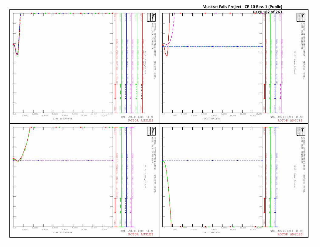
CHNL# 38: [ANGL468 [TCV GEN 6.90] [2]]
500.00
-1000.
CHNL# 39: [ANGL468 [TCV GEN 6.90] [3]]
500.00
-1000.
CHNL# 40: [ANGL473 [ROP G1 6.90] [1]]
500.00
-1000.
CHNL# 41: [ANGL478 [PHR GEN 2.30] [1]]
500.00
-1000.
CHNL# 42: [ANGL478 [PHR GEN 2.30] [2]]
500.00
-1000.
CHNL# 43: [ANGL478 [PHR GEN 2.30] [3]]
500.00
-1000.
SYSTEM INTEGRATION STUDY - REDUCED MODEL
(02) DROP GENERATOR
WED, JUL 21 2010 11:30TIME (SECONDS)
SIEMENS POWER
TECHNOLOGIES
INTERNATIONAL
R
0.01.5000
3.00004.5000
6.00007.5000
9.000010.500
12.00013.500
15.000
FILE: Case_02.out
ROTOR ANGLES
CHNL# 44: [ANGL483 [MRP G1 2.40] [1]]
500.00
-1000.
CHNL# 45: [ANGL486 [HCP G1 6.90] [1]]
500.00
-1000.
CHNL# 46: [ANGL488 [CAB G1 6.90] [1]]
500.00
-1000.
CHNL# 47: [ANGL871 [SLK G1 13.80] [1]]
500.00
-1000.
SYSTEM INTEGRATION STUDY - REDUCED MODEL
(02) DROP GENERATOR
WED, JUL 21 2010 11:30TIME (SECONDS)
SIEMENS POWER
TECHNOLOGIES
INTERNATIONAL
R
0.01.5000
3.00004.5000
6.00007.5000
9.000010.500
12.00013.500
15.000
FILE: Case_02.out
ROTOR ANGLES
CHNL# 56: [ANGL2201 [BDP G1 13.80][1]]
500.00
-1000.
CHNL# 57: [ANGL2207 [BDP G7 13.80][7]]
500.00
-1000.
CHNL# 58: [ANGL2221 [PHL SC1 13.80][1]]
500.00
-1000.
CHNL# 59: [ANGL2222 [PHL SC2 13.80][1]]
500.00
-1000.
SYSTEM INTEGRATION STUDY - REDUCED MODEL
(02) DROP GENERATOR
WED, JUL 21 2010 11:30TIME (SECONDS)
SIEMENS POWER
TECHNOLOGIES
INTERNATIONAL
R
0.01.5000
3.00004.5000
6.00007.5000
9.000010.500
12.00013.500
15.000
FILE: Case_02.out
ROTOR ANGLES
CHNL# 62: [ANGL2494 [SOL SC1 13.80][1]]
500.00
-1000.
CHNL# 63: [ANGL2495 [SOL SC2 13.80][2]]
500.00
-1000.
CHNL# 64: [ANGL2496 [SOL SC3 13.80][3]]
500.00
-1000.
SYSTEM INTEGRATION STUDY - REDUCED MODEL
(02) DROP GENERATOR
WED, JUL 21 2010 11:30TIME (SECONDS)
SIEMENS POWER
TECHNOLOGIES
INTERNATIONAL
R
0.01.5000
3.00004.5000
6.00007.5000
9.000010.500
12.00013.500
15.000
FILE: Case_02.out
ROTOR ANGLES
Muskrat Falls Project - CE-10 Rev. 1 (Public) Page 182 of 263

CHNL# 397: [SPD21 [ACG 1P2P 6.90] [1]]
0.05000
-0.0500
CHNL# 398: [SPD21 [ACG 1P2P 6.90] [2]]
0.05000
-0.0500
CHNL# 399: [SPD23 [ACG 3P4P 6.90] [1]]
0.05000
-0.0500
CHNL# 400: [SPD23 [ACG 3P4P 6.90] [2]]
0.05000
-0.0500
CHNL# 401: [SPD24 [ACG G7G8 6.90] [1]]
0.05000
-0.0500
CHNL# 402: [SPD24 [ACG G7G8 6.90] [2]]
0.05000
-0.0500
SYSTEM INTEGRATION STUDY - REDUCED MODEL
(02) DROP GENERATOR
WED, JUL 21 2010 11:30TIME (SECONDS)
SIEMENS POWER
TECHNOLOGIES
INTERNATIONAL
R
0.01.5000
3.00004.5000
6.00007.5000
9.000010.500
12.00013.500
15.000
FILE: Case_02.out
MACHINE SPEED
CHNL# 403: [SPD25 [ACG G5G6 6.90] [1]]
0.05000
-0.0500
CHNL# 404: [SPD25 [ACG G5G6 6.90] [2]]
0.05000
-0.0500
CHNL# 405: [SPD29 [ACGBG1-9 6.90] [1]]
0.05000
-0.0500
CHNL# 406: [SPD33 [ACG G4 6.90] [1]]
0.05000
-0.0500
CHNL# 407: [SPD34 [ACG G9 13.80] [1]]
0.05000
-0.0500
CHNL# 408: [SPD105 [CBF CBPP 6.60] [1]]
0.05000
-0.0500
SYSTEM INTEGRATION STUDY - REDUCED MODEL
(02) DROP GENERATOR
WED, JUL 21 2010 11:30TIME (SECONDS)
SIEMENS POWER
TECHNOLOGIES
INTERNATIONAL
R
0.01.5000
3.00004.5000
6.00007.5000
9.000010.500
12.00013.500
15.000
FILE: Case_02.out
MACHINE SPEED
CHNL# 409: [SPD109 [DLP G1-7 6.00] [1]]
0.05000
-0.0500
CHNL# 410: [SPD137 [CAT G1 13.80] [1]]
0.05000
-0.0500
CHNL# 411: [SPD138 [CAT G2 13.80] [1]]
0.05000
-0.0500
CHNL# 412: [SPD209 [SVL G1 13.80] [1]]
0.05000
-0.0500
CHNL# 413: [SPD220 [BDP G2-6 13.80] [2]]
0.05000
-0.0500
CHNL# 414: [SPD220 [BDP G2-6 13.80] [3]]
0.05000
-0.0500
SYSTEM INTEGRATION STUDY - REDUCED MODEL
(02) DROP GENERATOR
WED, JUL 21 2010 11:30TIME (SECONDS)
SIEMENS POWER
TECHNOLOGIES
INTERNATIONAL
R
0.01.5000
3.00004.5000
6.00007.5000
9.000010.500
12.00013.500
15.000
FILE: Case_02.out
MACHINE SPEED
CHNL# 415: [SPD220 [BDP G2-6 13.80] [4]]
0.05000
-0.0500
CHNL# 416: [SPD220 [BDP G2-6 13.80] [5]]
0.05000
-0.0500
CHNL# 417: [SPD220 [BDP G2-6 13.80] [6]]
0.05000
-0.0500
CHNL# 419: [SPD237 [HWD G1 13.80] [1]]
0.05000
-0.0500
CHNL# 420: [SPD250 [HLK G1 13.80] [1]]
0.05000
-0.0500
SYSTEM INTEGRATION STUDY - REDUCED MODEL
(02) DROP GENERATOR
WED, JUL 21 2010 11:30TIME (SECONDS)
SIEMENS POWER
TECHNOLOGIES
INTERNATIONAL
R
0.01.5000
3.00004.5000
6.00007.5000
9.000010.500
12.00013.500
15.000
FILE: Case_02.out
MACHINE SPEED
Muskrat Falls Project - CE-10 Rev. 1 (Public) Page 183 of 263

CHNL# 421: [SPD284 [PRV G1 4.20] [1]]
0.05000
-0.0500
CHNL# 422: [SPD290 [GCL G1 13.80] [1]]
0.05000
-0.0500
CHNL# 423: [SPD352 [SCV GEN 2.40] [1]]
0.05000
-0.0500
CHNL# 424: [SPD352 [SCV GEN 2.40] [2]]
0.05000
-0.0500
CHNL# 425: [SPD406 [USL G1 13.80] [1]]
0.05000
-0.0500
CHNL# 426: [SPD434 [HRP G1&G 16.00] [1]]
0.05000
-0.0500
SYSTEM INTEGRATION STUDY - REDUCED MODEL
(02) DROP GENERATOR
WED, JUL 21 2010 11:30TIME (SECONDS)
SIEMENS POWER
TECHNOLOGIES
INTERNATIONAL
R
0.01.5000
3.00004.5000
6.00007.5000
9.000010.500
12.00013.500
15.000
FILE: Case_02.out
MACHINE SPEED
CHNL# 427: [SPD436 [HRP G3 16.00] [1]]
0.05000
-0.0500
CHNL# 429: [SPD454 [TOP GEN 2.40] [1]]
0.05000
-0.0500
CHNL# 430: [SPD457 [GOU NP 66.00] [1]]
0.05000
-0.0500
CHNL# 431: [SPD464 [PBK G1 6.90] [1]]
0.05000
-0.0500
CHNL# 432: [SPD465 [MOB NP G 6.90] [1]]
0.05000
-0.0500
SYSTEM INTEGRATION STUDY - REDUCED MODEL
(02) DROP GENERATOR
WED, JUL 21 2010 11:30TIME (SECONDS)
SIEMENS POWER
TECHNOLOGIES
INTERNATIONAL
R
0.01.5000
3.00004.5000
6.00007.5000
9.000010.500
12.00013.500
15.000
FILE: Case_02.out
MACHINE SPEED
CHNL# 433: [SPD468 [TCV GEN 6.90] [1]]
0.05000
-0.0500
CHNL# 434: [SPD468 [TCV GEN 6.90] [2]]
0.05000
-0.0500
CHNL# 435: [SPD468 [TCV GEN 6.90] [3]]
0.05000
-0.0500
CHNL# 436: [SPD473 [ROP G1 6.90] [1]]
0.05000
-0.0500
CHNL# 437: [SPD478 [PHR GEN 2.30] [1]]
0.05000
-0.0500
CHNL# 438: [SPD478 [PHR GEN 2.30] [2]]
0.05000
-0.0500
SYSTEM INTEGRATION STUDY - REDUCED MODEL
(02) DROP GENERATOR
WED, JUL 21 2010 11:30TIME (SECONDS)
SIEMENS POWER
TECHNOLOGIES
INTERNATIONAL
R
0.01.5000
3.00004.5000
6.00007.5000
9.000010.500
12.00013.500
15.000
FILE: Case_02.out
MACHINE SPEED
CHNL# 439: [SPD478 [PHR GEN 2.30] [3]]
0.05000
-0.0500
CHNL# 440: [SPD483 [MRP G1 2.40] [1]]
0.05000
-0.0500
CHNL# 441: [SPD486 [HCP G1 6.90] [1]]
0.05000
-0.0500
CHNL# 442: [SPD488 [CAB G1 6.90] [1]]
0.05000
-0.0500
CHNL# 443: [SPD871 [SLK G1 13.80] [1]]
0.05000
-0.0500
SYSTEM INTEGRATION STUDY - REDUCED MODEL
(02) DROP GENERATOR
WED, JUL 21 2010 11:30TIME (SECONDS)
SIEMENS POWER
TECHNOLOGIES
INTERNATIONAL
R
0.01.5000
3.00004.5000
6.00007.5000
9.000010.500
12.00013.500
15.000
FILE: Case_02.out
MACHINE SPEED
Muskrat Falls Project - CE-10 Rev. 1 (Public) Page 184 of 263

CHNL# 444: [SPD2101 [CHF A1 15.00] [1]]
0.05000
-0.0500
CHNL# 445: [SPD2102 [CHF A2-A 15.00] [2]]
0.05000
-0.0500
CHNL# 446: [SPD2115 [MUSK G1- 15.00] [1]]
0.05000
-0.0500
CHNL# 447: [SPD2121 [GUL G1 15.00] [1]]
0.05000
-0.0500
CHNL# 448: [SPD2122 [GUL G2 15.00] [2]]
0.05000
-0.0500
CHNL# 449: [SPD2137 [HVY G1 13.80] [1]]
0.05000
-0.0500
SYSTEM INTEGRATION STUDY - REDUCED MODEL
(02) DROP GENERATOR
WED, JUL 21 2010 11:30TIME (SECONDS)
SIEMENS POWER
TECHNOLOGIES
INTERNATIONAL
R
0.01.5000
3.00004.5000
6.00007.5000
9.000010.500
12.00013.500
15.000
FILE: Case_02.out
LABRADOR MACHINE SPEED
CHNL# 458: [SPD2494 [SOL SC1 13.80][1]]
0.05000
-0.0500
CHNL# 459: [SPD2495 [SOL SC2 13.80][2]]
0.05000
-0.0500
CHNL# 460: [SPD2496 [SOL SC3 13.80][3]]
0.05000
-0.0500
SYSTEM INTEGRATION STUDY - REDUCED MODEL
(02) DROP GENERATOR
WED, JUL 21 2010 11:30TIME (SECONDS)
SIEMENS POWER
TECHNOLOGIES
INTERNATIONAL
R
0.01.5000
3.00004.5000
6.00007.5000
9.000010.500
12.00013.500
15.000
FILE: Case_02.out
MACHINE SPEED
Muskrat Falls Project - CE-10 Rev. 1 (Public) Page 185 of 263

CHNL# 628: 60.0*(1+[FREQ153 [DPD L64 66]])
62.000
58.000
CHNL# 629: 60.0*(1+[FREQ204 [SVL B2 66]])
62.000
58.000
CHNL# 630: 60.0*(1+[FREQ308 [BLK NPT3 66]])
62.000
58.000
CHNL# 631: 60.0*(1+[FREQ309 [BRB T2T3 66]])
62.000
58.000
CHNL# 632: 60.0*(1+[FREQ319 [DLK NP 66]])
62.000
58.000
CHNL# 633: 60.0*(1+[FREQ334 [OPD B2B5 66]])
62.000
58.000
SYSTEM INTEGRATION STUDY - REDUCED MODEL
(02) DROP GENERATOR
WED, JUL 21 2010 11:30TIME (SECONDS)
SIEMENS POWER
TECHNOLOGIES
INTERNATIONAL
R
0.01.5000
3.00004.5000
6.00007.5000
9.000010.500
12.00013.500
15.000
FILE: Case_02.out
BUS FREQUENCY
CHNL# 634: 60.0*(1+[FREQ335 [HWD B7B8 66]])
62.000
58.000
CHNL# 635: 60.0*(1+[FREQ336 [WAV B2 66]])
62.000
58.000
CHNL# 636: 60.0*(1+[FREQ337 [HRD B6B7 66]])
62.000
58.000
CHNL# 637: 60.0*(1+[FREQ345 [ULT TAP 66]])
62.000
58.000
CHNL# 638: 60.0*(1+[FREQ346 [ULT NP 66]])
62.000
58.000
CHNL# 639: 60.0*(1+[FREQ347 [SCV NP 66]])
62.000
58.000
SYSTEM INTEGRATION STUDY - REDUCED MODEL
(02) DROP GENERATOR
WED, JUL 21 2010 11:30TIME (SECONDS)
SIEMENS POWER
TECHNOLOGIES
INTERNATIONAL
R
0.01.5000
3.00004.5000
6.00007.5000
9.000010.500
12.00013.500
15.000
FILE: Case_02.out
BUS FREQUENCY
CHNL# 640: 60.0*(1+[FREQ348 [KEL NP 66]])
62.000
58.000
CHNL# 641: 60.0*(1+[FREQ349 [CHA NP 66]])
62.000
58.000
CHNL# 642: 60.0*(1+[FREQ455 [GDL NP 66]])
62.000
58.000
CHNL# 643: 60.0*(1+[FREQ457 [GOU NP 66]])
62.000
58.000
CHNL# 646: 60.0*(1+[FREQ467 [TCV NP 66]])
62.000
58.000
CHNL# 652: 60.0*(1+[FREQ482 [MRP NP 66]])
62.000
58.000
SYSTEM INTEGRATION STUDY - REDUCED MODEL
(02) DROP GENERATOR
WED, JUL 21 2010 11:30TIME (SECONDS)
SIEMENS POWER
TECHNOLOGIES
INTERNATIONAL
R
0.01.5000
3.00004.5000
6.00007.5000
9.000010.500
12.00013.500
15.000
FILE: Case_02.out
BUS FREQUENCY
CHNL# 658: 60.0*(1+[FREQ550 [MOB NP 66]])
62.000
58.000
CHNL# 659: 60.0*(1+[FREQ558 [ROP NP 66]])
62.000
58.000
CHNL# 664: 60.0*(1+[FREQ973 [GOU MID1 66]])
62.000
58.000
CHNL# 665: 60.0*(1+[FREQ982 [CHA MID1 66]])
62.000
58.000
CHNL# 666: 60.0*(1+[FREQ111 [DLK B1 138]])
62.000
58.000
CHNL# 667: 60.0*(1+[FREQ112 [IRV B1 138]])
62.000
58.000
SYSTEM INTEGRATION STUDY - REDUCED MODEL
(02) DROP GENERATOR
WED, JUL 21 2010 11:30TIME (SECONDS)
SIEMENS POWER
TECHNOLOGIES
INTERNATIONAL
R
0.01.5000
3.00004.5000
6.00007.5000
9.000010.500
12.00013.500
15.000
FILE: Case_02.out
BUS FREQUENCY
Muskrat Falls Project - CE-10 Rev. 1 (Public) Page 186 of 263

CHNL# 668: 60.0*(1+[FREQ113 [SPL B1 138]])
62.000
58.000
CHNL# 669: 60.0*(1+[FREQ203 [BBK B2 138]])
62.000
58.000
CHNL# 670: 60.0*(1+[FREQ212 [HLY B1 138]])
62.000
58.000
CHNL# 671: 60.0*(1+[FREQ213 [HLK L43 138]])
62.000
58.000
CHNL# 672: 60.0*(1+[FREQ217 [STB B3 138]])
62.000
58.000
CHNL# 673: 60.0*(1+[FREQ219 [SOK L22 138]])
62.000
58.000
SYSTEM INTEGRATION STUDY - REDUCED MODEL
(02) DROP GENERATOR
WED, JUL 21 2010 11:30TIME (SECONDS)
SIEMENS POWER
TECHNOLOGIES
INTERNATIONAL
R
0.01.5000
3.00004.5000
6.00007.5000
9.000010.500
12.00013.500
15.000
FILE: Case_02.out
BUS FREQUENCY
CHNL# 674: 60.0*(1+[FREQ223 [SSD B2B3 138]])
62.000
58.000
CHNL# 675: 60.0*(1+[FREQ224 [BLA L12 138]])
62.000
58.000
CHNL# 676: 60.0*(1+[FREQ225 [LLK NP 138]])
62.000
58.000
CHNL# 677: 60.0*(1+[FREQ232 [MKS L12 138]])
62.000
58.000
CHNL# 678: 60.0*(1+[FREQ310 [BLK NP 138]])
62.000
58.000
CHNL# 679: 60.0*(1+[FREQ311 [WAV B4 138]])
62.000
58.000
SYSTEM INTEGRATION STUDY - REDUCED MODEL
(02) DROP GENERATOR
WED, JUL 21 2010 11:30TIME (SECONDS)
SIEMENS POWER
TECHNOLOGIES
INTERNATIONAL
R
0.01.5000
3.00004.5000
6.00007.5000
9.000010.500
12.00013.500
15.000
FILE: Case_02.out
BUS FREQUENCY
CHNL# 680: 60.0*(1+[FREQ338 [HRD B8 138]])
62.000
58.000
CHNL# 681: 60.0*(1+[FREQ340 [HOL NP 138]])
62.000
58.000
CHNL# 682: 60.0*(1+[FREQ353 [SPF NP 138]])
62.000
58.000
CHNL# 683: 60.0*(1+[FREQ354 [COL NP 138]])
62.000
58.000
CHNL# 684: 60.0*(1+[FREQ357 [BRB NP 138]])
62.000
58.000
CHNL# 685: 60.0*(1+[FREQ359 [MSY NP 138]])
62.000
58.000
SYSTEM INTEGRATION STUDY - REDUCED MODEL
(02) DROP GENERATOR
WED, JUL 21 2010 11:30TIME (SECONDS)
SIEMENS POWER
TECHNOLOGIES
INTERNATIONAL
R
0.01.5000
3.00004.5000
6.00007.5000
9.000010.500
12.00013.500
15.000
FILE: Case_02.out
BUS FREQUENCY
CHNL# 686: 60.0*(1+[FREQ371 [SPO NP 138]])
62.000
58.000
CHNL# 687: 60.0*(1+[FREQ603 [BBK B3 138]])
62.000
58.000
CHNL# 692: 60.0*(1+[FREQ205 [BBK B1 230]])
62.000
58.000
CHNL# 693: 60.0*(1+[FREQ206 [SVL B1 230]])
62.000
58.000
CHNL# 694: 60.0*(1+[FREQ208 [MDR B1B5 230]])
62.000
58.000
SYSTEM INTEGRATION STUDY - REDUCED MODEL
(02) DROP GENERATOR
WED, JUL 21 2010 11:30TIME (SECONDS)
SIEMENS POWER
TECHNOLOGIES
INTERNATIONAL
R
0.01.5000
3.00004.5000
6.00007.5000
9.000010.500
12.00013.500
15.000
FILE: Case_02.out
BUS FREQUENCY
Muskrat Falls Project - CE-10 Rev. 1 (Public) Page 187 of 263

CHNL# 696: 60.0*(1+[FREQ215 [BUC B1 230]])
62.000
58.000
CHNL# 697: 60.0*(1+[FREQ216 [STB B1B2 230]])
62.000
58.000
CHNL# 701: 60.0*(1+[FREQ227 [CBC B1B2 230]])
62.000
58.000
CHNL# 702: 60.0*(1+[FREQ229 [WAV B1B3 230]])
62.000
58.000
CHNL# 703: 60.0*(1+[FREQ230 [LHR B1 230]])
62.000
58.000
CHNL# 704: 60.0*(1+[FREQ234 [HRD TS 230]])
62.000
58.000
SYSTEM INTEGRATION STUDY - REDUCED MODEL
(02) DROP GENERATOR
WED, JUL 21 2010 11:30TIME (SECONDS)
SIEMENS POWER
TECHNOLOGIES
INTERNATIONAL
R
0.01.5000
3.00004.5000
6.00007.5000
9.000010.500
12.00013.500
15.000
FILE: Case_02.out
BUS FREQUENCY
CHNL# 705: 60.0*(1+[FREQ236 [HWD B1B2 230]])
62.000
58.000
CHNL# 706: 60.0*(1+[FREQ238 [OPD B1 230]])
62.000
58.000
CHNL# 708: 60.0*(1+[FREQ261 [ACG GFL 230]])
62.000
58.000
CHNL# 709: 60.0*(1+[FREQ291 [GCL L63 230]])
62.000
58.000
CHNL# 710: 60.0*(1+[FREQ405 [USL L34 230]])
62.000
58.000
CHNL# 711: 60.0*(1+[FREQ912 [TL202X 230]])
62.000
58.000
SYSTEM INTEGRATION STUDY - REDUCED MODEL
(02) DROP GENERATOR
WED, JUL 21 2010 11:30TIME (SECONDS)
SIEMENS POWER
TECHNOLOGIES
INTERNATIONAL
R
0.01.5000
3.00004.5000
6.00007.5000
9.000010.500
12.00013.500
15.000
FILE: Case_02.out
BUS FREQUENCY
CHNL# 712: 60.0*(1+[FREQ916 [TL206X 230]])
62.000
58.000
CHNL# 713: 60.0*(1+[FREQ918 [TLNEWX 230]])
62.000
58.000
CHNL# 714: 60.0*(1+[FREQ2181 [TL202Y 230]])
62.000
58.000
CHNL# 715: 60.0*(1+[FREQ2182 [TL206Y 230]])
62.000
58.000
CHNL# 716: 60.0*(1+[FREQ2183 [TLNEWY 230]])
62.000
58.000
CHNL# 726: 60.0*(1+[FREQ2490 [SOL B1 230]])
62.000
58.000
SYSTEM INTEGRATION STUDY - REDUCED MODEL
(02) DROP GENERATOR
WED, JUL 21 2010 11:30TIME (SECONDS)
SIEMENS POWER
TECHNOLOGIES
INTERNATIONAL
R
0.01.5000
3.00004.5000
6.00007.5000
9.000010.500
12.00013.500
15.000
FILE: Case_02.out
BUS FREQUENCY
CHNL# 717: 60.0*(1+[FREQ2301 [CHF A1 B 230]])
62.000
58.000
CHNL# 718: 60.0*(1+[FREQ2302 [CHF A2 & 230]])
62.000
58.000
CHNL# 719: 60.0*(1+[FREQ2307 [WABUSH T 230]])
62.000
58.000
CHNL# 720: 60.0*(1+[FREQ2308 [GUL 230 230]])
62.000
58.000
CHNL# 724: 60.0*(1+[FREQ2341 [GUL T1 230]])
62.000
58.000
CHNL# 725: 60.0*(1+[FREQ2342 [GUL T2 230]])
62.000
58.000
SYSTEM INTEGRATION STUDY - REDUCED MODEL
(02) DROP GENERATOR
WED, JUL 21 2010 11:30TIME (SECONDS)
SIEMENS POWER
TECHNOLOGIES
INTERNATIONAL
R
0.01.5000
3.00004.5000
6.00007.5000
9.000010.500
12.00013.500
15.000
FILE: Case_02.out
LABRADOR BUS FREQUENCY
Muskrat Falls Project - CE-10 Rev. 1 (Public) Page 188 of 263

CHNL# 470: [VOLT115 [MDR B2B3 66]]
1.2000
0.0
CHNL# 471: [VOLT151 [BUC B2 66]]
1.2000
0.0
CHNL# 472: [VOLT152 [MDR B4 66]]
1.2000
0.0
CHNL# 473: [VOLT153 [DPD L64 66]]
1.2000
0.0
CHNL# 474: [VOLT204 [SVL B2 66]]
1.2000
0.0
CHNL# 475: [VOLT308 [BLK NPT3 66]]
1.2000
0.0
SYSTEM INTEGRATION STUDY - REDUCED MODEL
(02) DROP GENERATOR
WED, JUL 21 2010 11:30TIME (SECONDS)
SIEMENS POWER
TECHNOLOGIES
INTERNATIONAL
R
0.01.5000
3.00004.5000
6.00007.5000
9.000010.500
12.00013.500
15.000
FILE: Case_02.out
VOLTAGE
CHNL# 476: [VOLT309 [BRB T2T3 66]]
1.2000
0.0
CHNL# 477: [VOLT319 [DLK NP 66]]
1.2000
0.0
CHNL# 478: [VOLT334 [OPD B2B5 66]]
1.2000
0.0
CHNL# 479: [VOLT335 [HWD B7B8 66]]
1.2000
0.0
CHNL# 480: [VOLT336 [WAV B2 66]]
1.2000
0.0
CHNL# 481: [VOLT337 [HRD B6B7 66]]
1.2000
0.0
SYSTEM INTEGRATION STUDY - REDUCED MODEL
(02) DROP GENERATOR
WED, JUL 21 2010 11:30TIME (SECONDS)
SIEMENS POWER
TECHNOLOGIES
INTERNATIONAL
R
0.01.5000
3.00004.5000
6.00007.5000
9.000010.500
12.00013.500
15.000
FILE: Case_02.out
VOLTAGE
CHNL# 482: [VOLT345 [ULT TAP 66]]
1.2000
0.0
CHNL# 483: [VOLT346 [ULT NP 66]]
1.2000
0.0
CHNL# 484: [VOLT347 [SCV NP 66]]
1.2000
0.0
CHNL# 485: [VOLT348 [KEL NP 66]]
1.2000
0.0
CHNL# 486: [VOLT349 [CHA NP 66]]
1.2000
0.0
CHNL# 487: [VOLT455 [GDL NP 66]]
1.2000
0.0
SYSTEM INTEGRATION STUDY - REDUCED MODEL
(02) DROP GENERATOR
WED, JUL 21 2010 11:30TIME (SECONDS)
SIEMENS POWER
TECHNOLOGIES
INTERNATIONAL
R
0.01.5000
3.00004.5000
6.00007.5000
9.000010.500
12.00013.500
15.000
FILE: Case_02.out
VOLTAGE
CHNL# 488: [VOLT457 [GOU NP 66]]
1.2000
0.0
CHNL# 489: [VOLT463 [KEN NP 66]]
1.2000
0.0
CHNL# 490: [VOLT466 [KBR NP 66]]
1.2000
0.0
CHNL# 491: [VOLT467 [TCV NP 66]]
1.2000
0.0
CHNL# 492: [VOLT469 [MUN NP 66]]
1.2000
0.0
CHNL# 493: [VOLT471 [MOL NP 66]]
1.2000
0.0
SYSTEM INTEGRATION STUDY - REDUCED MODEL
(02) DROP GENERATOR
WED, JUL 21 2010 11:30TIME (SECONDS)
SIEMENS POWER
TECHNOLOGIES
INTERNATIONAL
R
0.01.5000
3.00004.5000
6.00007.5000
9.000010.500
12.00013.500
15.000
FILE: Case_02.out
VOLTAGE
Muskrat Falls Project - CE-10 Rev. 1 (Public) Page 189 of 263

CHNL# 494: [VOLT474 [PEP NP 66]]
1.2000
0.0
CHNL# 495: [VOLT479 [PUL NP 66]]
1.2000
0.0
CHNL# 496: [VOLT481 [RRD NP 66]]
1.2000
0.0
CHNL# 497: [VOLT482 [MRP NP 66]]
1.2000
0.0
CHNL# 498: [VOLT484 [SJM NP 66]]
1.2000
0.0
CHNL# 499: [VOLT485 [HCP NP 66]]
1.2000
0.0
SYSTEM INTEGRATION STUDY - REDUCED MODEL
(02) DROP GENERATOR
WED, JUL 21 2010 11:30TIME (SECONDS)
SIEMENS POWER
TECHNOLOGIES
INTERNATIONAL
R
0.01.5000
3.00004.5000
6.00007.5000
9.000010.500
12.00013.500
15.000
FILE: Case_02.out
VOLTAGE
CHNL# 500: [VOLT489 [SLA NP 66]]
1.2000
0.0
CHNL# 501: [VOLT492 [VIR NP 66]]
1.2000
0.0
CHNL# 502: [VOLT510 [BIG NP 66]]
1.2000
0.0
CHNL# 503: [VOLT550 [MOB NP 66]]
1.2000
0.0
CHNL# 504: [VOLT558 [ROP NP 66]]
1.2000
0.0
CHNL# 505: [VOLT576 [CAB NP 66]]
1.2000
0.0
SYSTEM INTEGRATION STUDY - REDUCED MODEL
(02) DROP GENERATOR
WED, JUL 21 2010 11:30TIME (SECONDS)
SIEMENS POWER
TECHNOLOGIES
INTERNATIONAL
R
0.01.5000
3.00004.5000
6.00007.5000
9.000010.500
12.00013.500
15.000
FILE: Case_02.out
VOLTAGE
CHNL# 506: [VOLT579 [FER NP 66]]
1.2000
0.0
CHNL# 507: [VOLT870 [SLK L80 66]]
1.2000
0.0
CHNL# 508: [VOLT920 [MOB MID3 66]]
1.2000
0.0
CHNL# 509: [VOLT973 [GOU MID1 66]]
1.2000
0.0
CHNL# 510: [VOLT982 [CHA MID1 66]]
1.2000
0.0
CHNL# 511: [VOLT111 [DLK B1 138]]
1.2000
0.0
SYSTEM INTEGRATION STUDY - REDUCED MODEL
(02) DROP GENERATOR
WED, JUL 21 2010 11:30TIME (SECONDS)
SIEMENS POWER
TECHNOLOGIES
INTERNATIONAL
R
0.01.5000
3.00004.5000
6.00007.5000
9.000010.500
12.00013.500
15.000
FILE: Case_02.out
VOLTAGE
CHNL# 512: [VOLT112 [IRV B1 138]]
1.2000
0.0
CHNL# 513: [VOLT113 [SPL B1 138]]
1.2000
0.0
CHNL# 514: [VOLT203 [BBK B2 138]]
1.2000
0.0
CHNL# 515: [VOLT212 [HLY B1 138]]
1.2000
0.0
CHNL# 516: [VOLT213 [HLK L43 138]]
1.2000
0.0
CHNL# 517: [VOLT217 [STB B3 138]]
1.2000
0.0
SYSTEM INTEGRATION STUDY - REDUCED MODEL
(02) DROP GENERATOR
WED, JUL 21 2010 11:30TIME (SECONDS)
SIEMENS POWER
TECHNOLOGIES
INTERNATIONAL
R
0.01.5000
3.00004.5000
6.00007.5000
9.000010.500
12.00013.500
15.000
FILE: Case_02.out
VOLTAGE
Muskrat Falls Project - CE-10 Rev. 1 (Public) Page 190 of 263

CHNL# 518: [VOLT219 [SOK L22 138]]
1.2000
0.0
CHNL# 519: [VOLT223 [SSD B2B3 138]]
1.2000
0.0
CHNL# 520: [VOLT224 [BLA L12 138]]
1.2000
0.0
CHNL# 521: [VOLT225 [LLK NP 138]]
1.2000
0.0
CHNL# 522: [VOLT232 [MKS L12 138]]
1.2000
0.0
CHNL# 523: [VOLT310 [BLK NP 138]]
1.2000
0.0
SYSTEM INTEGRATION STUDY - REDUCED MODEL
(02) DROP GENERATOR
WED, JUL 21 2010 11:30TIME (SECONDS)
SIEMENS POWER
TECHNOLOGIES
INTERNATIONAL
R
0.01.5000
3.00004.5000
6.00007.5000
9.000010.500
12.00013.500
15.000
FILE: Case_02.out
VOLTAGE
CHNL# 524: [VOLT311 [WAV B4 138]]
1.2000
0.0
CHNL# 525: [VOLT338 [HRD B8 138]]
1.2000
0.0
CHNL# 526: [VOLT340 [HOL NP 138]]
1.2000
0.0
CHNL# 527: [VOLT353 [SPF NP 138]]
1.2000
0.0
CHNL# 528: [VOLT354 [COL NP 138]]
1.2000
0.0
CHNL# 529: [VOLT357 [BRB NP 138]]
1.2000
0.0
SYSTEM INTEGRATION STUDY - REDUCED MODEL
(02) DROP GENERATOR
WED, JUL 21 2010 11:30TIME (SECONDS)
SIEMENS POWER
TECHNOLOGIES
INTERNATIONAL
R
0.01.5000
3.00004.5000
6.00007.5000
9.000010.500
12.00013.500
15.000
FILE: Case_02.out
VOLTAGE
CHNL# 530: [VOLT359 [MSY NP 138]]
1.2000
0.0
CHNL# 531: [VOLT371 [SPO NP 138]]
1.2000
0.0
CHNL# 532: [VOLT603 [BBK B3 138]]
1.2000
0.0
SYSTEM INTEGRATION STUDY - REDUCED MODEL
(02) DROP GENERATOR
WED, JUL 21 2010 11:30TIME (SECONDS)
SIEMENS POWER
TECHNOLOGIES
INTERNATIONAL
R
0.01.5000
3.00004.5000
6.00007.5000
9.000010.500
12.00013.500
15.000
FILE: Case_02.out
VOLTAGE
CHNL# 536: [VOLT136 [CAT L47 230]]
1.2000
0.0
CHNL# 537: [VOLT205 [BBK B1 230]]
1.2000
0.0
CHNL# 538: [VOLT206 [SVL B1 230]]
1.2000
0.0
CHNL# 539: [VOLT208 [MDR B1B5 230]]
1.2000
0.0
CHNL# 540: [VOLT211 [NLREFINE 230]]
1.2000
0.0
SYSTEM INTEGRATION STUDY - REDUCED MODEL
(02) DROP GENERATOR
WED, JUL 21 2010 11:30TIME (SECONDS)
SIEMENS POWER
TECHNOLOGIES
INTERNATIONAL
R
0.01.5000
3.00004.5000
6.00007.5000
9.000010.500
12.00013.500
15.000
FILE: Case_02.out
VOLTAGE
Muskrat Falls Project - CE-10 Rev. 1 (Public) Page 191 of 263

CHNL# 543: [VOLT218 [PIPERS_H 230]]
1.2000
0.0
CHNL# 544: [VOLT221 [BDE TS 230]]
1.2000
0.0
CHNL# 545: [VOLT222 [SSD B1 230]]
1.2000
0.0
CHNL# 546: [VOLT227 [CBC B1B2 230]]
1.2000
0.0
CHNL# 547: [VOLT229 [WAV B1B3 230]]
1.2000
0.0
SYSTEM INTEGRATION STUDY - REDUCED MODEL
(02) DROP GENERATOR
WED, JUL 21 2010 11:30TIME (SECONDS)
SIEMENS POWER
TECHNOLOGIES
INTERNATIONAL
R
0.01.5000
3.00004.5000
6.00007.5000
9.000010.500
12.00013.500
15.000
FILE: Case_02.out
VOLTAGE
CHNL# 548: [VOLT230 [LHR B1 230]]
1.2000
0.0
CHNL# 549: [VOLT234 [HRD TS 230]]
1.2000
0.0
CHNL# 550: [VOLT236 [HWD B1B2 230]]
1.2000
0.0
CHNL# 551: [VOLT238 [OPD B1 230]]
1.2000
0.0
CHNL# 552: [VOLT260 [ACS SVL 230]]
1.2000
0.0
SYSTEM INTEGRATION STUDY - REDUCED MODEL
(02) DROP GENERATOR
WED, JUL 21 2010 11:30TIME (SECONDS)
SIEMENS POWER
TECHNOLOGIES
INTERNATIONAL
R
0.01.5000
3.00004.5000
6.00007.5000
9.000010.500
12.00013.500
15.000
FILE: Case_02.out
VOLTAGE
CHNL# 553: [VOLT261 [ACG GFL 230]]
1.2000
0.0
CHNL# 554: [VOLT291 [GCL L63 230]]
1.2000
0.0
CHNL# 555: [VOLT405 [USL L34 230]]
1.2000
0.0
CHNL# 556: [VOLT912 [TL202X 230]]
1.2000
0.0
CHNL# 557: [VOLT916 [TL206X 230]]
1.2000
0.0
SYSTEM INTEGRATION STUDY - REDUCED MODEL
(02) DROP GENERATOR
WED, JUL 21 2010 11:30TIME (SECONDS)
SIEMENS POWER
TECHNOLOGIES
INTERNATIONAL
R
0.01.5000
3.00004.5000
6.00007.5000
9.000010.500
12.00013.500
15.000
FILE: Case_02.out
VOLTAGE
CHNL# 558: [VOLT918 [TLNEWX 230]]
1.2000
0.0
CHNL# 559: [VOLT2181 [TL202Y 230]]
1.2000
0.0
CHNL# 560: [VOLT2182 [TL206Y 230]]
1.2000
0.0
CHNL# 561: [VOLT2183 [TLNEWY 230]]
1.2000
0.0
SYSTEM INTEGRATION STUDY - REDUCED MODEL
(02) DROP GENERATOR
WED, JUL 21 2010 11:30TIME (SECONDS)
SIEMENS POWER
TECHNOLOGIES
INTERNATIONAL
R
0.01.5000
3.00004.5000
6.00007.5000
9.000010.500
12.00013.500
15.000
FILE: Case_02.out
VOLTAGE
Muskrat Falls Project - CE-10 Rev. 1 (Public) Page 192 of 263

CHNL# 61: [ANGL2490 [SOL B1 230.00][1]]
500.00
-500.0
CHNL# 457: [SPD2490 [SOL B1 230.00][1]]
0.50000
-0.5000
SYSTEM INTEGRATION STUDY - REDUCED MODEL
(02) DROP GENERATOR
WED, MAR 03 2010 8:40TIME (SECONDS)
SIEMENS POWER
TECHNOLOGIES
INTERNATIONAL
R
0.01.5000
3.00004.5000
6.00007.5000
9.000010.500
12.00013.500
15.000
FILE: Case_02.out
MACHINE BUS 2490
CHNL# 127: 100*[POWR2490 [SOL B1 230.00][1]]
50.000
-50.00
CHNL# 193: 100*[VARS2490 [SOL B1 230.00][1]]
50.000
-50.00
SYSTEM INTEGRATION STUDY - REDUCED MODEL
(02) DROP GENERATOR
WED, MAR 03 2010 8:40TIME (SECONDS)
SIEMENS POWER
TECHNOLOGIES
INTERNATIONAL
R
0.01.5000
3.00004.5000
6.00007.5000
9.000010.500
12.00013.500
15.000
FILE: Case_02.out
MACHINE BUS 2490
CHNL# 773: 100*[SOLP_P1_MW]
100.00
-400.0
CHNL# 775: 100*[SOLP_P2_MW]
100.00
-400.0
SYSTEM INTEGRATION STUDY - REDUCED MODEL
(02) DROP GENERATOR
WED, MAR 03 2010 8:40TIME (SECONDS)
SIEMENS POWER
TECHNOLOGIES
INTERNATIONAL
R
0.01.5000
3.00004.5000
6.00007.5000
9.000010.500
12.00013.500
15.000
FILE: Case_02.out
HVDC, MW
CHNL# 774: 100*[SOLP_P2_MVAR]
400.00
-100.0
CHNL# 776: 100*[SOLP_P2_MVAR]
400.00
-100.0
SYSTEM INTEGRATION STUDY - REDUCED MODEL
(02) DROP GENERATOR
WED, MAR 03 2010 8:40TIME (SECONDS)
SIEMENS POWER
TECHNOLOGIES
INTERNATIONAL
R
0.01.5000
3.00004.5000
6.00007.5000
9.000010.500
12.00013.500
15.000
FILE: Case_02.out
HVDC, MVAR
Muskrat Falls Project - CE-10 Rev. 1 (Public) Page 193 of 263

CHNL# 1: [ANGL21 [ACG 1P2P 6.90] [1]]
500.00
-1000.
CHNL# 2: [ANGL21 [ACG 1P2P 6.90] [2]]
500.00
-1000.
CHNL# 3: [ANGL23 [ACG 3P4P 6.90] [1]]
500.00
-1000.
CHNL# 4: [ANGL23 [ACG 3P4P 6.90] [2]]
500.00
-1000.
CHNL# 5: [ANGL24 [ACG G7G8 6.90] [1]]
500.00
-1000.
SYSTEM INTEGRATION STUDY - REDUCED MODEL
(03) DROP GENERATOR
WED, JUL 21 2010 11:30TIME (SECONDS)
SIEMENS POWER
TECHNOLOGIES
INTERNATIONAL
R
0.01.5000
3.00004.5000
6.00007.5000
9.000010.500
12.00013.500
15.000
FILE: Case_03.out
ROTOR ANGLES
CHNL# 6: [ANGL24 [ACG G7G8 6.90] [2]]
500.00
-1000.
CHNL# 7: [ANGL25 [ACG G5G6 6.90] [1]]
500.00
-1000.
CHNL# 8: [ANGL25 [ACG G5G6 6.90] [2]]
500.00
-1000.
CHNL# 9: [ANGL29 [ACGBG1-9 6.90] [1]]
500.00
-1000.
CHNL# 10: [ANGL33 [ACG G4 6.90] [1]]
500.00
-1000.
SYSTEM INTEGRATION STUDY - REDUCED MODEL
(03) DROP GENERATOR
WED, JUL 21 2010 11:30TIME (SECONDS)
SIEMENS POWER
TECHNOLOGIES
INTERNATIONAL
R
0.01.5000
3.00004.5000
6.00007.5000
9.000010.500
12.00013.500
15.000
FILE: Case_03.out
ROTOR ANGLES
CHNL# 11: [ANGL34 [ACG G9 13.80] [1]]
500.00
-1000.
CHNL# 12: [ANGL105 [CBF CBPP 6.60] [1]]
500.00
-1000.
CHNL# 13: [ANGL109 [DLP G1-7 6.00] [1]]
500.00
-1000.
CHNL# 14: [ANGL137 [CAT G1 13.80] [1]]
500.00
-1000.
CHNL# 15: [ANGL138 [CAT G2 13.80] [1]]
500.00
-1000.
SYSTEM INTEGRATION STUDY - REDUCED MODEL
(03) DROP GENERATOR
WED, JUL 21 2010 11:30TIME (SECONDS)
SIEMENS POWER
TECHNOLOGIES
INTERNATIONAL
R
0.01.5000
3.00004.5000
6.00007.5000
9.000010.500
12.00013.500
15.000
FILE: Case_03.out
ROTOR ANGLES
CHNL# 16: [ANGL209 [SVL G1 13.80] [1]]
500.00
-1000.
CHNL# 17: [ANGL220 [BDP G2-6 13.80] [2]]
500.00
-1000.
CHNL# 18: [ANGL220 [BDP G2-6 13.80] [3]]
500.00
-1000.
CHNL# 19: [ANGL220 [BDP G2-6 13.80] [4]]
500.00
-1000.
CHNL# 20: [ANGL220 [BDP G2-6 13.80] [5]]
500.00
-1000.
SYSTEM INTEGRATION STUDY - REDUCED MODEL
(03) DROP GENERATOR
WED, JUL 21 2010 11:30TIME (SECONDS)
SIEMENS POWER
TECHNOLOGIES
INTERNATIONAL
R
0.01.5000
3.00004.5000
6.00007.5000
9.000010.500
12.00013.500
15.000
FILE: Case_03.out
ROTOR ANGLES
Muskrat Falls Project - CE-10 Rev. 1 (Public) Page 194 of 263

CHNL# 21: [ANGL220 [BDP G2-6 13.80] [6]]
500.00
-1000.
CHNL# 23: [ANGL237 [HWD G1 13.80] [1]]
500.00
-1000.
CHNL# 24: [ANGL250 [HLK G1 13.80] [1]]
500.00
-1000.
SYSTEM INTEGRATION STUDY - REDUCED MODEL
(03) DROP GENERATOR
WED, JUL 21 2010 11:30TIME (SECONDS)
SIEMENS POWER
TECHNOLOGIES
INTERNATIONAL
R
0.01.5000
3.00004.5000
6.00007.5000
9.000010.500
12.00013.500
15.000
FILE: Case_03.out
ROTOR ANGLES
CHNL# 25: [ANGL284 [PRV G1 4.20] [1]]
500.00
-1000.
CHNL# 26: [ANGL290 [GCL G1 13.80] [1]]
500.00
-1000.
CHNL# 27: [ANGL352 [SCV GEN 2.40] [1]]
500.00
-1000.
CHNL# 28: [ANGL352 [SCV GEN 2.40] [2]]
500.00
-1000.
SYSTEM INTEGRATION STUDY - REDUCED MODEL
(03) DROP GENERATOR
WED, JUL 21 2010 11:30TIME (SECONDS)
SIEMENS POWER
TECHNOLOGIES
INTERNATIONAL
R
0.01.5000
3.00004.5000
6.00007.5000
9.000010.500
12.00013.500
15.000
FILE: Case_03.out
ROTOR ANGLES
CHNL# 29: [ANGL406 [USL G1 13.80] [1]]
500.00
-1000.
CHNL# 30: [ANGL434 [HRP G1&G 16.00] [1]]
500.00
-1000.
CHNL# 31: [ANGL436 [HRP G3 16.00] [1]]
500.00
-1000.
SYSTEM INTEGRATION STUDY - REDUCED MODEL
(03) DROP GENERATOR
WED, JUL 21 2010 11:30TIME (SECONDS)
SIEMENS POWER
TECHNOLOGIES
INTERNATIONAL
R
0.01.5000
3.00004.5000
6.00007.5000
9.000010.500
12.00013.500
15.000
FILE: Case_03.out
ROTOR ANGLES
CHNL# 33: [ANGL454 [TOP GEN 2.40] [1]]
500.00
-1000.
CHNL# 34: [ANGL457 [GOU NP 66.00] [1]]
500.00
-1000.
CHNL# 35: [ANGL464 [PBK G1 6.90] [1]]
500.00
-1000.
CHNL# 36: [ANGL465 [MOB NP G 6.90] [1]]
500.00
-1000.
CHNL# 37: [ANGL468 [TCV GEN 6.90] [1]]
500.00
-1000.
SYSTEM INTEGRATION STUDY - REDUCED MODEL
(03) DROP GENERATOR
WED, JUL 21 2010 11:30TIME (SECONDS)
SIEMENS POWER
TECHNOLOGIES
INTERNATIONAL
R
0.01.5000
3.00004.5000
6.00007.5000
9.000010.500
12.00013.500
15.000
FILE: Case_03.out
ROTOR ANGLES
Muskrat Falls Project - CE-10 Rev. 1 (Public) Page 195 of 263

CHNL# 38: [ANGL468 [TCV GEN 6.90] [2]]
500.00
-1000.
CHNL# 39: [ANGL468 [TCV GEN 6.90] [3]]
500.00
-1000.
CHNL# 40: [ANGL473 [ROP G1 6.90] [1]]
500.00
-1000.
CHNL# 41: [ANGL478 [PHR GEN 2.30] [1]]
500.00
-1000.
CHNL# 42: [ANGL478 [PHR GEN 2.30] [2]]
500.00
-1000.
CHNL# 43: [ANGL478 [PHR GEN 2.30] [3]]
500.00
-1000.
SYSTEM INTEGRATION STUDY - REDUCED MODEL
(03) DROP GENERATOR
WED, JUL 21 2010 11:30TIME (SECONDS)
SIEMENS POWER
TECHNOLOGIES
INTERNATIONAL
R
0.01.5000
3.00004.5000
6.00007.5000
9.000010.500
12.00013.500
15.000
FILE: Case_03.out
ROTOR ANGLES
CHNL# 44: [ANGL483 [MRP G1 2.40] [1]]
500.00
-1000.
CHNL# 45: [ANGL486 [HCP G1 6.90] [1]]
500.00
-1000.
CHNL# 46: [ANGL488 [CAB G1 6.90] [1]]
500.00
-1000.
CHNL# 47: [ANGL871 [SLK G1 13.80] [1]]
500.00
-1000.
SYSTEM INTEGRATION STUDY - REDUCED MODEL
(03) DROP GENERATOR
WED, JUL 21 2010 11:30TIME (SECONDS)
SIEMENS POWER
TECHNOLOGIES
INTERNATIONAL
R
0.01.5000
3.00004.5000
6.00007.5000
9.000010.500
12.00013.500
15.000
FILE: Case_03.out
ROTOR ANGLES
CHNL# 56: [ANGL2201 [BDP G1 13.80][1]]
500.00
-1000.
CHNL# 57: [ANGL2207 [BDP G7 13.80][7]]
500.00
-1000.
CHNL# 58: [ANGL2221 [PHL SC1 13.80][1]]
500.00
-1000.
CHNL# 59: [ANGL2222 [PHL SC2 13.80][1]]
500.00
-1000.
SYSTEM INTEGRATION STUDY - REDUCED MODEL
(03) DROP GENERATOR
WED, JUL 21 2010 11:30TIME (SECONDS)
SIEMENS POWER
TECHNOLOGIES
INTERNATIONAL
R
0.01.5000
3.00004.5000
6.00007.5000
9.000010.500
12.00013.500
15.000
FILE: Case_03.out
ROTOR ANGLES
CHNL# 62: [ANGL2494 [SOL SC1 13.80][1]]
500.00
-1000.
CHNL# 63: [ANGL2495 [SOL SC2 13.80][2]]
500.00
-1000.
CHNL# 64: [ANGL2496 [SOL SC3 13.80][3]]
500.00
-1000.
SYSTEM INTEGRATION STUDY - REDUCED MODEL
(03) DROP GENERATOR
WED, JUL 21 2010 11:30TIME (SECONDS)
SIEMENS POWER
TECHNOLOGIES
INTERNATIONAL
R
0.01.5000
3.00004.5000
6.00007.5000
9.000010.500
12.00013.500
15.000
FILE: Case_03.out
ROTOR ANGLES
Muskrat Falls Project - CE-10 Rev. 1 (Public) Page 196 of 263

CHNL# 397: [SPD21 [ACG 1P2P 6.90] [1]]
0.05000
-0.0500
CHNL# 398: [SPD21 [ACG 1P2P 6.90] [2]]
0.05000
-0.0500
CHNL# 399: [SPD23 [ACG 3P4P 6.90] [1]]
0.05000
-0.0500
CHNL# 400: [SPD23 [ACG 3P4P 6.90] [2]]
0.05000
-0.0500
CHNL# 401: [SPD24 [ACG G7G8 6.90] [1]]
0.05000
-0.0500
CHNL# 402: [SPD24 [ACG G7G8 6.90] [2]]
0.05000
-0.0500
SYSTEM INTEGRATION STUDY - REDUCED MODEL
(03) DROP GENERATOR
WED, JUL 21 2010 11:30TIME (SECONDS)
SIEMENS POWER
TECHNOLOGIES
INTERNATIONAL
R
0.01.5000
3.00004.5000
6.00007.5000
9.000010.500
12.00013.500
15.000
FILE: Case_03.out
MACHINE SPEED
CHNL# 403: [SPD25 [ACG G5G6 6.90] [1]]
0.05000
-0.0500
CHNL# 404: [SPD25 [ACG G5G6 6.90] [2]]
0.05000
-0.0500
CHNL# 405: [SPD29 [ACGBG1-9 6.90] [1]]
0.05000
-0.0500
CHNL# 406: [SPD33 [ACG G4 6.90] [1]]
0.05000
-0.0500
CHNL# 407: [SPD34 [ACG G9 13.80] [1]]
0.05000
-0.0500
CHNL# 408: [SPD105 [CBF CBPP 6.60] [1]]
0.05000
-0.0500
SYSTEM INTEGRATION STUDY - REDUCED MODEL
(03) DROP GENERATOR
WED, JUL 21 2010 11:30TIME (SECONDS)
SIEMENS POWER
TECHNOLOGIES
INTERNATIONAL
R
0.01.5000
3.00004.5000
6.00007.5000
9.000010.500
12.00013.500
15.000
FILE: Case_03.out
MACHINE SPEED
CHNL# 409: [SPD109 [DLP G1-7 6.00] [1]]
0.05000
-0.0500
CHNL# 410: [SPD137 [CAT G1 13.80] [1]]
0.05000
-0.0500
CHNL# 411: [SPD138 [CAT G2 13.80] [1]]
0.05000
-0.0500
CHNL# 412: [SPD209 [SVL G1 13.80] [1]]
0.05000
-0.0500
CHNL# 413: [SPD220 [BDP G2-6 13.80] [2]]
0.05000
-0.0500
CHNL# 414: [SPD220 [BDP G2-6 13.80] [3]]
0.05000
-0.0500
SYSTEM INTEGRATION STUDY - REDUCED MODEL
(03) DROP GENERATOR
WED, JUL 21 2010 11:30TIME (SECONDS)
SIEMENS POWER
TECHNOLOGIES
INTERNATIONAL
R
0.01.5000
3.00004.5000
6.00007.5000
9.000010.500
12.00013.500
15.000
FILE: Case_03.out
MACHINE SPEED
CHNL# 415: [SPD220 [BDP G2-6 13.80] [4]]
0.05000
-0.0500
CHNL# 416: [SPD220 [BDP G2-6 13.80] [5]]
0.05000
-0.0500
CHNL# 417: [SPD220 [BDP G2-6 13.80] [6]]
0.05000
-0.0500
CHNL# 419: [SPD237 [HWD G1 13.80] [1]]
0.05000
-0.0500
CHNL# 420: [SPD250 [HLK G1 13.80] [1]]
0.05000
-0.0500
SYSTEM INTEGRATION STUDY - REDUCED MODEL
(03) DROP GENERATOR
WED, JUL 21 2010 11:30TIME (SECONDS)
SIEMENS POWER
TECHNOLOGIES
INTERNATIONAL
R
0.01.5000
3.00004.5000
6.00007.5000
9.000010.500
12.00013.500
15.000
FILE: Case_03.out
MACHINE SPEED
Muskrat Falls Project - CE-10 Rev. 1 (Public) Page 197 of 263

CHNL# 421: [SPD284 [PRV G1 4.20] [1]]
0.05000
-0.0500
CHNL# 422: [SPD290 [GCL G1 13.80] [1]]
0.05000
-0.0500
CHNL# 423: [SPD352 [SCV GEN 2.40] [1]]
0.05000
-0.0500
CHNL# 424: [SPD352 [SCV GEN 2.40] [2]]
0.05000
-0.0500
CHNL# 425: [SPD406 [USL G1 13.80] [1]]
0.05000
-0.0500
CHNL# 426: [SPD434 [HRP G1&G 16.00] [1]]
0.05000
-0.0500
SYSTEM INTEGRATION STUDY - REDUCED MODEL
(03) DROP GENERATOR
WED, JUL 21 2010 11:30TIME (SECONDS)
SIEMENS POWER
TECHNOLOGIES
INTERNATIONAL
R
0.01.5000
3.00004.5000
6.00007.5000
9.000010.500
12.00013.500
15.000
FILE: Case_03.out
MACHINE SPEED
CHNL# 427: [SPD436 [HRP G3 16.00] [1]]
0.05000
-0.0500
CHNL# 429: [SPD454 [TOP GEN 2.40] [1]]
0.05000
-0.0500
CHNL# 430: [SPD457 [GOU NP 66.00] [1]]
0.05000
-0.0500
CHNL# 431: [SPD464 [PBK G1 6.90] [1]]
0.05000
-0.0500
CHNL# 432: [SPD465 [MOB NP G 6.90] [1]]
0.05000
-0.0500
SYSTEM INTEGRATION STUDY - REDUCED MODEL
(03) DROP GENERATOR
WED, JUL 21 2010 11:30TIME (SECONDS)
SIEMENS POWER
TECHNOLOGIES
INTERNATIONAL
R
0.01.5000
3.00004.5000
6.00007.5000
9.000010.500
12.00013.500
15.000
FILE: Case_03.out
MACHINE SPEED
CHNL# 433: [SPD468 [TCV GEN 6.90] [1]]
0.05000
-0.0500
CHNL# 434: [SPD468 [TCV GEN 6.90] [2]]
0.05000
-0.0500
CHNL# 435: [SPD468 [TCV GEN 6.90] [3]]
0.05000
-0.0500
CHNL# 436: [SPD473 [ROP G1 6.90] [1]]
0.05000
-0.0500
CHNL# 437: [SPD478 [PHR GEN 2.30] [1]]
0.05000
-0.0500
CHNL# 438: [SPD478 [PHR GEN 2.30] [2]]
0.05000
-0.0500
SYSTEM INTEGRATION STUDY - REDUCED MODEL
(03) DROP GENERATOR
WED, JUL 21 2010 11:30TIME (SECONDS)
SIEMENS POWER
TECHNOLOGIES
INTERNATIONAL
R
0.01.5000
3.00004.5000
6.00007.5000
9.000010.500
12.00013.500
15.000
FILE: Case_03.out
MACHINE SPEED
CHNL# 439: [SPD478 [PHR GEN 2.30] [3]]
0.05000
-0.0500
CHNL# 440: [SPD483 [MRP G1 2.40] [1]]
0.05000
-0.0500
CHNL# 441: [SPD486 [HCP G1 6.90] [1]]
0.05000
-0.0500
CHNL# 442: [SPD488 [CAB G1 6.90] [1]]
0.05000
-0.0500
CHNL# 443: [SPD871 [SLK G1 13.80] [1]]
0.05000
-0.0500
SYSTEM INTEGRATION STUDY - REDUCED MODEL
(03) DROP GENERATOR
WED, JUL 21 2010 11:30TIME (SECONDS)
SIEMENS POWER
TECHNOLOGIES
INTERNATIONAL
R
0.01.5000
3.00004.5000
6.00007.5000
9.000010.500
12.00013.500
15.000
FILE: Case_03.out
MACHINE SPEED
Muskrat Falls Project - CE-10 Rev. 1 (Public) Page 198 of 263

CHNL# 444: [SPD2101 [CHF A1 15.00] [1]]
0.05000
-0.0500
CHNL# 445: [SPD2102 [CHF A2-A 15.00] [2]]
0.05000
-0.0500
CHNL# 446: [SPD2115 [MUSK G1- 15.00] [1]]
0.05000
-0.0500
CHNL# 447: [SPD2121 [GUL G1 15.00] [1]]
0.05000
-0.0500
CHNL# 448: [SPD2122 [GUL G2 15.00] [2]]
0.05000
-0.0500
CHNL# 449: [SPD2137 [HVY G1 13.80] [1]]
0.05000
-0.0500
SYSTEM INTEGRATION STUDY - REDUCED MODEL
(03) DROP GENERATOR
WED, JUL 21 2010 11:30TIME (SECONDS)
SIEMENS POWER
TECHNOLOGIES
INTERNATIONAL
R
0.01.5000
3.00004.5000
6.00007.5000
9.000010.500
12.00013.500
15.000
FILE: Case_03.out
LABRADOR MACHINE SPEED
CHNL# 458: [SPD2494 [SOL SC1 13.80][1]]
0.05000
-0.0500
CHNL# 459: [SPD2495 [SOL SC2 13.80][2]]
0.05000
-0.0500
CHNL# 460: [SPD2496 [SOL SC3 13.80][3]]
0.05000
-0.0500
SYSTEM INTEGRATION STUDY - REDUCED MODEL
(03) DROP GENERATOR
WED, JUL 21 2010 11:30TIME (SECONDS)
SIEMENS POWER
TECHNOLOGIES
INTERNATIONAL
R
0.01.5000
3.00004.5000
6.00007.5000
9.000010.500
12.00013.500
15.000
FILE: Case_03.out
MACHINE SPEED
Muskrat Falls Project - CE-10 Rev. 1 (Public) Page 199 of 263

CHNL# 628: 60.0*(1+[FREQ153 [DPD L64 66]])
62.000
58.000
CHNL# 629: 60.0*(1+[FREQ204 [SVL B2 66]])
62.000
58.000
CHNL# 630: 60.0*(1+[FREQ308 [BLK NPT3 66]])
62.000
58.000
CHNL# 631: 60.0*(1+[FREQ309 [BRB T2T3 66]])
62.000
58.000
CHNL# 632: 60.0*(1+[FREQ319 [DLK NP 66]])
62.000
58.000
CHNL# 633: 60.0*(1+[FREQ334 [OPD B2B5 66]])
62.000
58.000
SYSTEM INTEGRATION STUDY - REDUCED MODEL
(03) DROP GENERATOR
WED, JUL 21 2010 11:30TIME (SECONDS)
SIEMENS POWER
TECHNOLOGIES
INTERNATIONAL
R
0.01.5000
3.00004.5000
6.00007.5000
9.000010.500
12.00013.500
15.000
FILE: Case_03.out
BUS FREQUENCY
CHNL# 634: 60.0*(1+[FREQ335 [HWD B7B8 66]])
62.000
58.000
CHNL# 635: 60.0*(1+[FREQ336 [WAV B2 66]])
62.000
58.000
CHNL# 636: 60.0*(1+[FREQ337 [HRD B6B7 66]])
62.000
58.000
CHNL# 637: 60.0*(1+[FREQ345 [ULT TAP 66]])
62.000
58.000
CHNL# 638: 60.0*(1+[FREQ346 [ULT NP 66]])
62.000
58.000
CHNL# 639: 60.0*(1+[FREQ347 [SCV NP 66]])
62.000
58.000
SYSTEM INTEGRATION STUDY - REDUCED MODEL
(03) DROP GENERATOR
WED, JUL 21 2010 11:30TIME (SECONDS)
SIEMENS POWER
TECHNOLOGIES
INTERNATIONAL
R
0.01.5000
3.00004.5000
6.00007.5000
9.000010.500
12.00013.500
15.000
FILE: Case_03.out
BUS FREQUENCY
CHNL# 640: 60.0*(1+[FREQ348 [KEL NP 66]])
62.000
58.000
CHNL# 641: 60.0*(1+[FREQ349 [CHA NP 66]])
62.000
58.000
CHNL# 642: 60.0*(1+[FREQ455 [GDL NP 66]])
62.000
58.000
CHNL# 643: 60.0*(1+[FREQ457 [GOU NP 66]])
62.000
58.000
CHNL# 646: 60.0*(1+[FREQ467 [TCV NP 66]])
62.000
58.000
CHNL# 652: 60.0*(1+[FREQ482 [MRP NP 66]])
62.000
58.000
SYSTEM INTEGRATION STUDY - REDUCED MODEL
(03) DROP GENERATOR
WED, JUL 21 2010 11:30TIME (SECONDS)
SIEMENS POWER
TECHNOLOGIES
INTERNATIONAL
R
0.01.5000
3.00004.5000
6.00007.5000
9.000010.500
12.00013.500
15.000
FILE: Case_03.out
BUS FREQUENCY
CHNL# 658: 60.0*(1+[FREQ550 [MOB NP 66]])
62.000
58.000
CHNL# 659: 60.0*(1+[FREQ558 [ROP NP 66]])
62.000
58.000
CHNL# 664: 60.0*(1+[FREQ973 [GOU MID1 66]])
62.000
58.000
CHNL# 665: 60.0*(1+[FREQ982 [CHA MID1 66]])
62.000
58.000
CHNL# 666: 60.0*(1+[FREQ111 [DLK B1 138]])
62.000
58.000
CHNL# 667: 60.0*(1+[FREQ112 [IRV B1 138]])
62.000
58.000
SYSTEM INTEGRATION STUDY - REDUCED MODEL
(03) DROP GENERATOR
WED, JUL 21 2010 11:30TIME (SECONDS)
SIEMENS POWER
TECHNOLOGIES
INTERNATIONAL
R
0.01.5000
3.00004.5000
6.00007.5000
9.000010.500
12.00013.500
15.000
FILE: Case_03.out
BUS FREQUENCY
Muskrat Falls Project - CE-10 Rev. 1 (Public) Page 200 of 263

CHNL# 668: 60.0*(1+[FREQ113 [SPL B1 138]])
62.000
58.000
CHNL# 669: 60.0*(1+[FREQ203 [BBK B2 138]])
62.000
58.000
CHNL# 670: 60.0*(1+[FREQ212 [HLY B1 138]])
62.000
58.000
CHNL# 671: 60.0*(1+[FREQ213 [HLK L43 138]])
62.000
58.000
CHNL# 672: 60.0*(1+[FREQ217 [STB B3 138]])
62.000
58.000
CHNL# 673: 60.0*(1+[FREQ219 [SOK L22 138]])
62.000
58.000
SYSTEM INTEGRATION STUDY - REDUCED MODEL
(03) DROP GENERATOR
WED, JUL 21 2010 11:30TIME (SECONDS)
SIEMENS POWER
TECHNOLOGIES
INTERNATIONAL
R
0.01.5000
3.00004.5000
6.00007.5000
9.000010.500
12.00013.500
15.000
FILE: Case_03.out
BUS FREQUENCY
CHNL# 674: 60.0*(1+[FREQ223 [SSD B2B3 138]])
62.000
58.000
CHNL# 675: 60.0*(1+[FREQ224 [BLA L12 138]])
62.000
58.000
CHNL# 676: 60.0*(1+[FREQ225 [LLK NP 138]])
62.000
58.000
CHNL# 677: 60.0*(1+[FREQ232 [MKS L12 138]])
62.000
58.000
CHNL# 678: 60.0*(1+[FREQ310 [BLK NP 138]])
62.000
58.000
CHNL# 679: 60.0*(1+[FREQ311 [WAV B4 138]])
62.000
58.000
SYSTEM INTEGRATION STUDY - REDUCED MODEL
(03) DROP GENERATOR
WED, JUL 21 2010 11:30TIME (SECONDS)
SIEMENS POWER
TECHNOLOGIES
INTERNATIONAL
R
0.01.5000
3.00004.5000
6.00007.5000
9.000010.500
12.00013.500
15.000
FILE: Case_03.out
BUS FREQUENCY
CHNL# 680: 60.0*(1+[FREQ338 [HRD B8 138]])
62.000
58.000
CHNL# 681: 60.0*(1+[FREQ340 [HOL NP 138]])
62.000
58.000
CHNL# 682: 60.0*(1+[FREQ353 [SPF NP 138]])
62.000
58.000
CHNL# 683: 60.0*(1+[FREQ354 [COL NP 138]])
62.000
58.000
CHNL# 684: 60.0*(1+[FREQ357 [BRB NP 138]])
62.000
58.000
CHNL# 685: 60.0*(1+[FREQ359 [MSY NP 138]])
62.000
58.000
SYSTEM INTEGRATION STUDY - REDUCED MODEL
(03) DROP GENERATOR
WED, JUL 21 2010 11:30TIME (SECONDS)
SIEMENS POWER
TECHNOLOGIES
INTERNATIONAL
R
0.01.5000
3.00004.5000
6.00007.5000
9.000010.500
12.00013.500
15.000
FILE: Case_03.out
BUS FREQUENCY
CHNL# 686: 60.0*(1+[FREQ371 [SPO NP 138]])
62.000
58.000
CHNL# 687: 60.0*(1+[FREQ603 [BBK B3 138]])
62.000
58.000
CHNL# 692: 60.0*(1+[FREQ205 [BBK B1 230]])
62.000
58.000
CHNL# 693: 60.0*(1+[FREQ206 [SVL B1 230]])
62.000
58.000
CHNL# 694: 60.0*(1+[FREQ208 [MDR B1B5 230]])
62.000
58.000
SYSTEM INTEGRATION STUDY - REDUCED MODEL
(03) DROP GENERATOR
WED, JUL 21 2010 11:30TIME (SECONDS)
SIEMENS POWER
TECHNOLOGIES
INTERNATIONAL
R
0.01.5000
3.00004.5000
6.00007.5000
9.000010.500
12.00013.500
15.000
FILE: Case_03.out
BUS FREQUENCY
Muskrat Falls Project - CE-10 Rev. 1 (Public) Page 201 of 263

CHNL# 696: 60.0*(1+[FREQ215 [BUC B1 230]])
62.000
58.000
CHNL# 697: 60.0*(1+[FREQ216 [STB B1B2 230]])
62.000
58.000
CHNL# 701: 60.0*(1+[FREQ227 [CBC B1B2 230]])
62.000
58.000
CHNL# 702: 60.0*(1+[FREQ229 [WAV B1B3 230]])
62.000
58.000
CHNL# 703: 60.0*(1+[FREQ230 [LHR B1 230]])
62.000
58.000
CHNL# 704: 60.0*(1+[FREQ234 [HRD TS 230]])
62.000
58.000
SYSTEM INTEGRATION STUDY - REDUCED MODEL
(03) DROP GENERATOR
WED, JUL 21 2010 11:30TIME (SECONDS)
SIEMENS POWER
TECHNOLOGIES
INTERNATIONAL
R
0.01.5000
3.00004.5000
6.00007.5000
9.000010.500
12.00013.500
15.000
FILE: Case_03.out
BUS FREQUENCY
CHNL# 705: 60.0*(1+[FREQ236 [HWD B1B2 230]])
62.000
58.000
CHNL# 706: 60.0*(1+[FREQ238 [OPD B1 230]])
62.000
58.000
CHNL# 708: 60.0*(1+[FREQ261 [ACG GFL 230]])
62.000
58.000
CHNL# 709: 60.0*(1+[FREQ291 [GCL L63 230]])
62.000
58.000
CHNL# 710: 60.0*(1+[FREQ405 [USL L34 230]])
62.000
58.000
CHNL# 711: 60.0*(1+[FREQ912 [TL202X 230]])
62.000
58.000
SYSTEM INTEGRATION STUDY - REDUCED MODEL
(03) DROP GENERATOR
WED, JUL 21 2010 11:30TIME (SECONDS)
SIEMENS POWER
TECHNOLOGIES
INTERNATIONAL
R
0.01.5000
3.00004.5000
6.00007.5000
9.000010.500
12.00013.500
15.000
FILE: Case_03.out
BUS FREQUENCY
CHNL# 712: 60.0*(1+[FREQ916 [TL206X 230]])
62.000
58.000
CHNL# 713: 60.0*(1+[FREQ918 [TLNEWX 230]])
62.000
58.000
CHNL# 714: 60.0*(1+[FREQ2181 [TL202Y 230]])
62.000
58.000
CHNL# 715: 60.0*(1+[FREQ2182 [TL206Y 230]])
62.000
58.000
CHNL# 716: 60.0*(1+[FREQ2183 [TLNEWY 230]])
62.000
58.000
CHNL# 726: 60.0*(1+[FREQ2490 [SOL B1 230]])
62.000
58.000
SYSTEM INTEGRATION STUDY - REDUCED MODEL
(03) DROP GENERATOR
WED, JUL 21 2010 11:30TIME (SECONDS)
SIEMENS POWER
TECHNOLOGIES
INTERNATIONAL
R
0.01.5000
3.00004.5000
6.00007.5000
9.000010.500
12.00013.500
15.000
FILE: Case_03.out
BUS FREQUENCY
CHNL# 717: 60.0*(1+[FREQ2301 [CHF A1 B 230]])
62.000
58.000
CHNL# 718: 60.0*(1+[FREQ2302 [CHF A2 & 230]])
62.000
58.000
CHNL# 719: 60.0*(1+[FREQ2307 [WABUSH T 230]])
62.000
58.000
CHNL# 720: 60.0*(1+[FREQ2308 [GUL 230 230]])
62.000
58.000
CHNL# 724: 60.0*(1+[FREQ2341 [GUL T1 230]])
62.000
58.000
CHNL# 725: 60.0*(1+[FREQ2342 [GUL T2 230]])
62.000
58.000
SYSTEM INTEGRATION STUDY - REDUCED MODEL
(03) DROP GENERATOR
WED, JUL 21 2010 11:30TIME (SECONDS)
SIEMENS POWER
TECHNOLOGIES
INTERNATIONAL
R
0.01.5000
3.00004.5000
6.00007.5000
9.000010.500
12.00013.500
15.000
FILE: Case_03.out
LABRADOR BUS FREQUENCY
Muskrat Falls Project - CE-10 Rev. 1 (Public) Page 202 of 263

CHNL# 470: [VOLT115 [MDR B2B3 66]]
1.2000
0.0
CHNL# 471: [VOLT151 [BUC B2 66]]
1.2000
0.0
CHNL# 472: [VOLT152 [MDR B4 66]]
1.2000
0.0
CHNL# 473: [VOLT153 [DPD L64 66]]
1.2000
0.0
CHNL# 474: [VOLT204 [SVL B2 66]]
1.2000
0.0
CHNL# 475: [VOLT308 [BLK NPT3 66]]
1.2000
0.0
SYSTEM INTEGRATION STUDY - REDUCED MODEL
(03) DROP GENERATOR
WED, JUL 21 2010 11:30TIME (SECONDS)
SIEMENS POWER
TECHNOLOGIES
INTERNATIONAL
R
0.01.5000
3.00004.5000
6.00007.5000
9.000010.500
12.00013.500
15.000
FILE: Case_03.out
VOLTAGE
CHNL# 476: [VOLT309 [BRB T2T3 66]]
1.2000
0.0
CHNL# 477: [VOLT319 [DLK NP 66]]
1.2000
0.0
CHNL# 478: [VOLT334 [OPD B2B5 66]]
1.2000
0.0
CHNL# 479: [VOLT335 [HWD B7B8 66]]
1.2000
0.0
CHNL# 480: [VOLT336 [WAV B2 66]]
1.2000
0.0
CHNL# 481: [VOLT337 [HRD B6B7 66]]
1.2000
0.0
SYSTEM INTEGRATION STUDY - REDUCED MODEL
(03) DROP GENERATOR
WED, JUL 21 2010 11:30TIME (SECONDS)
SIEMENS POWER
TECHNOLOGIES
INTERNATIONAL
R
0.01.5000
3.00004.5000
6.00007.5000
9.000010.500
12.00013.500
15.000
FILE: Case_03.out
VOLTAGE
CHNL# 482: [VOLT345 [ULT TAP 66]]
1.2000
0.0
CHNL# 483: [VOLT346 [ULT NP 66]]
1.2000
0.0
CHNL# 484: [VOLT347 [SCV NP 66]]
1.2000
0.0
CHNL# 485: [VOLT348 [KEL NP 66]]
1.2000
0.0
CHNL# 486: [VOLT349 [CHA NP 66]]
1.2000
0.0
CHNL# 487: [VOLT455 [GDL NP 66]]
1.2000
0.0
SYSTEM INTEGRATION STUDY - REDUCED MODEL
(03) DROP GENERATOR
WED, JUL 21 2010 11:30TIME (SECONDS)
SIEMENS POWER
TECHNOLOGIES
INTERNATIONAL
R
0.01.5000
3.00004.5000
6.00007.5000
9.000010.500
12.00013.500
15.000
FILE: Case_03.out
VOLTAGE
CHNL# 488: [VOLT457 [GOU NP 66]]
1.2000
0.0
CHNL# 489: [VOLT463 [KEN NP 66]]
1.2000
0.0
CHNL# 490: [VOLT466 [KBR NP 66]]
1.2000
0.0
CHNL# 491: [VOLT467 [TCV NP 66]]
1.2000
0.0
CHNL# 492: [VOLT469 [MUN NP 66]]
1.2000
0.0
CHNL# 493: [VOLT471 [MOL NP 66]]
1.2000
0.0
SYSTEM INTEGRATION STUDY - REDUCED MODEL
(03) DROP GENERATOR
WED, JUL 21 2010 11:30TIME (SECONDS)
SIEMENS POWER
TECHNOLOGIES
INTERNATIONAL
R
0.01.5000
3.00004.5000
6.00007.5000
9.000010.500
12.00013.500
15.000
FILE: Case_03.out
VOLTAGE
Muskrat Falls Project - CE-10 Rev. 1 (Public) Page 203 of 263

CHNL# 494: [VOLT474 [PEP NP 66]]
1.2000
0.0
CHNL# 495: [VOLT479 [PUL NP 66]]
1.2000
0.0
CHNL# 496: [VOLT481 [RRD NP 66]]
1.2000
0.0
CHNL# 497: [VOLT482 [MRP NP 66]]
1.2000
0.0
CHNL# 498: [VOLT484 [SJM NP 66]]
1.2000
0.0
CHNL# 499: [VOLT485 [HCP NP 66]]
1.2000
0.0
SYSTEM INTEGRATION STUDY - REDUCED MODEL
(03) DROP GENERATOR
WED, JUL 21 2010 11:30TIME (SECONDS)
SIEMENS POWER
TECHNOLOGIES
INTERNATIONAL
R
0.01.5000
3.00004.5000
6.00007.5000
9.000010.500
12.00013.500
15.000
FILE: Case_03.out
VOLTAGE
CHNL# 500: [VOLT489 [SLA NP 66]]
1.2000
0.0
CHNL# 501: [VOLT492 [VIR NP 66]]
1.2000
0.0
CHNL# 502: [VOLT510 [BIG NP 66]]
1.2000
0.0
CHNL# 503: [VOLT550 [MOB NP 66]]
1.2000
0.0
CHNL# 504: [VOLT558 [ROP NP 66]]
1.2000
0.0
CHNL# 505: [VOLT576 [CAB NP 66]]
1.2000
0.0
SYSTEM INTEGRATION STUDY - REDUCED MODEL
(03) DROP GENERATOR
WED, JUL 21 2010 11:30TIME (SECONDS)
SIEMENS POWER
TECHNOLOGIES
INTERNATIONAL
R
0.01.5000
3.00004.5000
6.00007.5000
9.000010.500
12.00013.500
15.000
FILE: Case_03.out
VOLTAGE
CHNL# 506: [VOLT579 [FER NP 66]]
1.2000
0.0
CHNL# 507: [VOLT870 [SLK L80 66]]
1.2000
0.0
CHNL# 508: [VOLT920 [MOB MID3 66]]
1.2000
0.0
CHNL# 509: [VOLT973 [GOU MID1 66]]
1.2000
0.0
CHNL# 510: [VOLT982 [CHA MID1 66]]
1.2000
0.0
CHNL# 511: [VOLT111 [DLK B1 138]]
1.2000
0.0
SYSTEM INTEGRATION STUDY - REDUCED MODEL
(03) DROP GENERATOR
WED, JUL 21 2010 11:30TIME (SECONDS)
SIEMENS POWER
TECHNOLOGIES
INTERNATIONAL
R
0.01.5000
3.00004.5000
6.00007.5000
9.000010.500
12.00013.500
15.000
FILE: Case_03.out
VOLTAGE
CHNL# 512: [VOLT112 [IRV B1 138]]
1.2000
0.0
CHNL# 513: [VOLT113 [SPL B1 138]]
1.2000
0.0
CHNL# 514: [VOLT203 [BBK B2 138]]
1.2000
0.0
CHNL# 515: [VOLT212 [HLY B1 138]]
1.2000
0.0
CHNL# 516: [VOLT213 [HLK L43 138]]
1.2000
0.0
CHNL# 517: [VOLT217 [STB B3 138]]
1.2000
0.0
SYSTEM INTEGRATION STUDY - REDUCED MODEL
(03) DROP GENERATOR
WED, JUL 21 2010 11:30TIME (SECONDS)
SIEMENS POWER
TECHNOLOGIES
INTERNATIONAL
R
0.01.5000
3.00004.5000
6.00007.5000
9.000010.500
12.00013.500
15.000
FILE: Case_03.out
VOLTAGE
Muskrat Falls Project - CE-10 Rev. 1 (Public) Page 204 of 263

CHNL# 518: [VOLT219 [SOK L22 138]]
1.2000
0.0
CHNL# 519: [VOLT223 [SSD B2B3 138]]
1.2000
0.0
CHNL# 520: [VOLT224 [BLA L12 138]]
1.2000
0.0
CHNL# 521: [VOLT225 [LLK NP 138]]
1.2000
0.0
CHNL# 522: [VOLT232 [MKS L12 138]]
1.2000
0.0
CHNL# 523: [VOLT310 [BLK NP 138]]
1.2000
0.0
SYSTEM INTEGRATION STUDY - REDUCED MODEL
(03) DROP GENERATOR
WED, JUL 21 2010 11:30TIME (SECONDS)
SIEMENS POWER
TECHNOLOGIES
INTERNATIONAL
R
0.01.5000
3.00004.5000
6.00007.5000
9.000010.500
12.00013.500
15.000
FILE: Case_03.out
VOLTAGE
CHNL# 524: [VOLT311 [WAV B4 138]]
1.2000
0.0
CHNL# 525: [VOLT338 [HRD B8 138]]
1.2000
0.0
CHNL# 526: [VOLT340 [HOL NP 138]]
1.2000
0.0
CHNL# 527: [VOLT353 [SPF NP 138]]
1.2000
0.0
CHNL# 528: [VOLT354 [COL NP 138]]
1.2000
0.0
CHNL# 529: [VOLT357 [BRB NP 138]]
1.2000
0.0
SYSTEM INTEGRATION STUDY - REDUCED MODEL
(03) DROP GENERATOR
WED, JUL 21 2010 11:30TIME (SECONDS)
SIEMENS POWER
TECHNOLOGIES
INTERNATIONAL
R
0.01.5000
3.00004.5000
6.00007.5000
9.000010.500
12.00013.500
15.000
FILE: Case_03.out
VOLTAGE
CHNL# 530: [VOLT359 [MSY NP 138]]
1.2000
0.0
CHNL# 531: [VOLT371 [SPO NP 138]]
1.2000
0.0
CHNL# 532: [VOLT603 [BBK B3 138]]
1.2000
0.0
SYSTEM INTEGRATION STUDY - REDUCED MODEL
(03) DROP GENERATOR
WED, JUL 21 2010 11:30TIME (SECONDS)
SIEMENS POWER
TECHNOLOGIES
INTERNATIONAL
R
0.01.5000
3.00004.5000
6.00007.5000
9.000010.500
12.00013.500
15.000
FILE: Case_03.out
VOLTAGE
CHNL# 536: [VOLT136 [CAT L47 230]]
1.2000
0.0
CHNL# 537: [VOLT205 [BBK B1 230]]
1.2000
0.0
CHNL# 538: [VOLT206 [SVL B1 230]]
1.2000
0.0
CHNL# 539: [VOLT208 [MDR B1B5 230]]
1.2000
0.0
CHNL# 540: [VOLT211 [NLREFINE 230]]
1.2000
0.0
SYSTEM INTEGRATION STUDY - REDUCED MODEL
(03) DROP GENERATOR
WED, JUL 21 2010 11:30TIME (SECONDS)
SIEMENS POWER
TECHNOLOGIES
INTERNATIONAL
R
0.01.5000
3.00004.5000
6.00007.5000
9.000010.500
12.00013.500
15.000
FILE: Case_03.out
VOLTAGE
Muskrat Falls Project - CE-10 Rev. 1 (Public) Page 205 of 263

CHNL# 543: [VOLT218 [PIPERS_H 230]]
1.2000
0.0
CHNL# 544: [VOLT221 [BDE TS 230]]
1.2000
0.0
CHNL# 545: [VOLT222 [SSD B1 230]]
1.2000
0.0
CHNL# 546: [VOLT227 [CBC B1B2 230]]
1.2000
0.0
CHNL# 547: [VOLT229 [WAV B1B3 230]]
1.2000
0.0
SYSTEM INTEGRATION STUDY - REDUCED MODEL
(03) DROP GENERATOR
WED, JUL 21 2010 11:30TIME (SECONDS)
SIEMENS POWER
TECHNOLOGIES
INTERNATIONAL
R
0.01.5000
3.00004.5000
6.00007.5000
9.000010.500
12.00013.500
15.000
FILE: Case_03.out
VOLTAGE
CHNL# 548: [VOLT230 [LHR B1 230]]
1.2000
0.0
CHNL# 549: [VOLT234 [HRD TS 230]]
1.2000
0.0
CHNL# 550: [VOLT236 [HWD B1B2 230]]
1.2000
0.0
CHNL# 551: [VOLT238 [OPD B1 230]]
1.2000
0.0
CHNL# 552: [VOLT260 [ACS SVL 230]]
1.2000
0.0
SYSTEM INTEGRATION STUDY - REDUCED MODEL
(03) DROP GENERATOR
WED, JUL 21 2010 11:30TIME (SECONDS)
SIEMENS POWER
TECHNOLOGIES
INTERNATIONAL
R
0.01.5000
3.00004.5000
6.00007.5000
9.000010.500
12.00013.500
15.000
FILE: Case_03.out
VOLTAGE
CHNL# 553: [VOLT261 [ACG GFL 230]]
1.2000
0.0
CHNL# 554: [VOLT291 [GCL L63 230]]
1.2000
0.0
CHNL# 555: [VOLT405 [USL L34 230]]
1.2000
0.0
CHNL# 556: [VOLT912 [TL202X 230]]
1.2000
0.0
CHNL# 557: [VOLT916 [TL206X 230]]
1.2000
0.0
SYSTEM INTEGRATION STUDY - REDUCED MODEL
(03) DROP GENERATOR
WED, JUL 21 2010 11:30TIME (SECONDS)
SIEMENS POWER
TECHNOLOGIES
INTERNATIONAL
R
0.01.5000
3.00004.5000
6.00007.5000
9.000010.500
12.00013.500
15.000
FILE: Case_03.out
VOLTAGE
CHNL# 558: [VOLT918 [TLNEWX 230]]
1.2000
0.0
CHNL# 559: [VOLT2181 [TL202Y 230]]
1.2000
0.0
CHNL# 560: [VOLT2182 [TL206Y 230]]
1.2000
0.0
CHNL# 561: [VOLT2183 [TLNEWY 230]]
1.2000
0.0
SYSTEM INTEGRATION STUDY - REDUCED MODEL
(03) DROP GENERATOR
WED, JUL 21 2010 11:30TIME (SECONDS)
SIEMENS POWER
TECHNOLOGIES
INTERNATIONAL
R
0.01.5000
3.00004.5000
6.00007.5000
9.000010.500
12.00013.500
15.000
FILE: Case_03.out
VOLTAGE
Muskrat Falls Project - CE-10 Rev. 1 (Public) Page 206 of 263
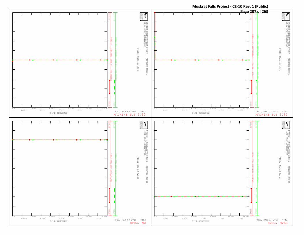
CHNL# 61: [ANGL2490 [SOL B1 230.00][1]]
500.00
-500.0
CHNL# 457: [SPD2490 [SOL B1 230.00][1]]
0.50000
-0.5000
SYSTEM INTEGRATION STUDY - REDUCED MODEL
(03) DROP GENERATOR
WED, MAR 03 2010 8:52TIME (SECONDS)
SIEMENS POWER
TECHNOLOGIES
INTERNATIONAL
R
0.01.5000
3.00004.5000
6.00007.5000
9.000010.500
12.00013.500
15.000
FILE: Case_03.out
MACHINE BUS 2490
CHNL# 127: 100*[POWR2490 [SOL B1 230.00][1]]
50.000
-50.00
CHNL# 193: 100*[VARS2490 [SOL B1 230.00][1]]
50.000
-50.00
SYSTEM INTEGRATION STUDY - REDUCED MODEL
(03) DROP GENERATOR
WED, MAR 03 2010 8:52TIME (SECONDS)
SIEMENS POWER
TECHNOLOGIES
INTERNATIONAL
R
0.01.5000
3.00004.5000
6.00007.5000
9.000010.500
12.00013.500
15.000
FILE: Case_03.out
MACHINE BUS 2490
CHNL# 773: 100*[SOLP_P1_MW]
100.00
-400.0
CHNL# 775: 100*[SOLP_P2_MW]
100.00
-400.0
SYSTEM INTEGRATION STUDY - REDUCED MODEL
(03) DROP GENERATOR
WED, MAR 03 2010 8:52TIME (SECONDS)
SIEMENS POWER
TECHNOLOGIES
INTERNATIONAL
R
0.01.5000
3.00004.5000
6.00007.5000
9.000010.500
12.00013.500
15.000
FILE: Case_03.out
HVDC, MW
CHNL# 774: 100*[SOLP_P2_MVAR]
400.00
-100.0
CHNL# 776: 100*[SOLP_P2_MVAR]
400.00
-100.0
SYSTEM INTEGRATION STUDY - REDUCED MODEL
(03) DROP GENERATOR
WED, MAR 03 2010 8:52TIME (SECONDS)
SIEMENS POWER
TECHNOLOGIES
INTERNATIONAL
R
0.01.5000
3.00004.5000
6.00007.5000
9.000010.500
12.00013.500
15.000
FILE: Case_03.out
HVDC, MVAR
Muskrat Falls Project - CE-10 Rev. 1 (Public) Page 207 of 263
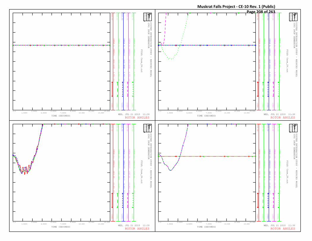
CHNL# 1: [ANGL21 [ACG 1P2P 6.90] [1]]
500.00
-1000.
CHNL# 2: [ANGL21 [ACG 1P2P 6.90] [2]]
500.00
-1000.
CHNL# 3: [ANGL23 [ACG 3P4P 6.90] [1]]
500.00
-1000.
CHNL# 4: [ANGL23 [ACG 3P4P 6.90] [2]]
500.00
-1000.
CHNL# 5: [ANGL24 [ACG G7G8 6.90] [1]]
500.00
-1000.
SYSTEM INTEGRATION STUDY - REDUCED MODEL
(04) DROP GENERATOR
WED, JUL 21 2010 11:30TIME (SECONDS)
SIEMENS POWER
TECHNOLOGIES
INTERNATIONAL
R
0.01.5000
3.00004.5000
6.00007.5000
9.000010.500
12.00013.500
15.000
FILE: Case_04.out
ROTOR ANGLES
CHNL# 6: [ANGL24 [ACG G7G8 6.90] [2]]
500.00
-1000.
CHNL# 7: [ANGL25 [ACG G5G6 6.90] [1]]
500.00
-1000.
CHNL# 8: [ANGL25 [ACG G5G6 6.90] [2]]
500.00
-1000.
CHNL# 9: [ANGL29 [ACGBG1-9 6.90] [1]]
500.00
-1000.
CHNL# 10: [ANGL33 [ACG G4 6.90] [1]]
500.00
-1000.
SYSTEM INTEGRATION STUDY - REDUCED MODEL
(04) DROP GENERATOR
WED, JUL 21 2010 11:30TIME (SECONDS)
SIEMENS POWER
TECHNOLOGIES
INTERNATIONAL
R
0.01.5000
3.00004.5000
6.00007.5000
9.000010.500
12.00013.500
15.000
FILE: Case_04.out
ROTOR ANGLES
CHNL# 11: [ANGL34 [ACG G9 13.80] [1]]
500.00
-1000.
CHNL# 12: [ANGL105 [CBF CBPP 6.60] [1]]
500.00
-1000.
CHNL# 13: [ANGL109 [DLP G1-7 6.00] [1]]
500.00
-1000.
CHNL# 14: [ANGL137 [CAT G1 13.80] [1]]
500.00
-1000.
CHNL# 15: [ANGL138 [CAT G2 13.80] [1]]
500.00
-1000.
SYSTEM INTEGRATION STUDY - REDUCED MODEL
(04) DROP GENERATOR
WED, JUL 21 2010 11:30TIME (SECONDS)
SIEMENS POWER
TECHNOLOGIES
INTERNATIONAL
R
0.01.5000
3.00004.5000
6.00007.5000
9.000010.500
12.00013.500
15.000
FILE: Case_04.out
ROTOR ANGLES
CHNL# 16: [ANGL209 [SVL G1 13.80] [1]]
500.00
-1000.
CHNL# 17: [ANGL220 [BDP G2-6 13.80] [2]]
500.00
-1000.
CHNL# 18: [ANGL220 [BDP G2-6 13.80] [3]]
500.00
-1000.
CHNL# 19: [ANGL220 [BDP G2-6 13.80] [4]]
500.00
-1000.
CHNL# 20: [ANGL220 [BDP G2-6 13.80] [5]]
500.00
-1000.
SYSTEM INTEGRATION STUDY - REDUCED MODEL
(04) DROP GENERATOR
WED, JUL 21 2010 11:30TIME (SECONDS)
SIEMENS POWER
TECHNOLOGIES
INTERNATIONAL
R
0.01.5000
3.00004.5000
6.00007.5000
9.000010.500
12.00013.500
15.000
FILE: Case_04.out
ROTOR ANGLES
Muskrat Falls Project - CE-10 Rev. 1 (Public) Page 208 of 263

CHNL# 21: [ANGL220 [BDP G2-6 13.80] [6]]
500.00
-1000.
CHNL# 23: [ANGL237 [HWD G1 13.80] [1]]
500.00
-1000.
CHNL# 24: [ANGL250 [HLK G1 13.80] [1]]
500.00
-1000.
SYSTEM INTEGRATION STUDY - REDUCED MODEL
(04) DROP GENERATOR
WED, JUL 21 2010 11:30TIME (SECONDS)
SIEMENS POWER
TECHNOLOGIES
INTERNATIONAL
R
0.01.5000
3.00004.5000
6.00007.5000
9.000010.500
12.00013.500
15.000
FILE: Case_04.out
ROTOR ANGLES
CHNL# 25: [ANGL284 [PRV G1 4.20] [1]]
500.00
-1000.
CHNL# 26: [ANGL290 [GCL G1 13.80] [1]]
500.00
-1000.
CHNL# 27: [ANGL352 [SCV GEN 2.40] [1]]
500.00
-1000.
CHNL# 28: [ANGL352 [SCV GEN 2.40] [2]]
500.00
-1000.
SYSTEM INTEGRATION STUDY - REDUCED MODEL
(04) DROP GENERATOR
WED, JUL 21 2010 11:30TIME (SECONDS)
SIEMENS POWER
TECHNOLOGIES
INTERNATIONAL
R
0.01.5000
3.00004.5000
6.00007.5000
9.000010.500
12.00013.500
15.000
FILE: Case_04.out
ROTOR ANGLES
CHNL# 29: [ANGL406 [USL G1 13.80] [1]]
500.00
-1000.
CHNL# 30: [ANGL434 [HRP G1&G 16.00] [1]]
500.00
-1000.
CHNL# 31: [ANGL436 [HRP G3 16.00] [1]]
500.00
-1000.
SYSTEM INTEGRATION STUDY - REDUCED MODEL
(04) DROP GENERATOR
WED, JUL 21 2010 11:30TIME (SECONDS)
SIEMENS POWER
TECHNOLOGIES
INTERNATIONAL
R
0.01.5000
3.00004.5000
6.00007.5000
9.000010.500
12.00013.500
15.000
FILE: Case_04.out
ROTOR ANGLES
CHNL# 33: [ANGL454 [TOP GEN 2.40] [1]]
500.00
-1000.
CHNL# 34: [ANGL457 [GOU NP 66.00] [1]]
500.00
-1000.
CHNL# 35: [ANGL464 [PBK G1 6.90] [1]]
500.00
-1000.
CHNL# 36: [ANGL465 [MOB NP G 6.90] [1]]
500.00
-1000.
CHNL# 37: [ANGL468 [TCV GEN 6.90] [1]]
500.00
-1000.
SYSTEM INTEGRATION STUDY - REDUCED MODEL
(04) DROP GENERATOR
WED, JUL 21 2010 11:30TIME (SECONDS)
SIEMENS POWER
TECHNOLOGIES
INTERNATIONAL
R
0.01.5000
3.00004.5000
6.00007.5000
9.000010.500
12.00013.500
15.000
FILE: Case_04.out
ROTOR ANGLES
Muskrat Falls Project - CE-10 Rev. 1 (Public) Page 209 of 263

CHNL# 38: [ANGL468 [TCV GEN 6.90] [2]]
500.00
-1000.
CHNL# 39: [ANGL468 [TCV GEN 6.90] [3]]
500.00
-1000.
CHNL# 40: [ANGL473 [ROP G1 6.90] [1]]
500.00
-1000.
CHNL# 41: [ANGL478 [PHR GEN 2.30] [1]]
500.00
-1000.
CHNL# 42: [ANGL478 [PHR GEN 2.30] [2]]
500.00
-1000.
CHNL# 43: [ANGL478 [PHR GEN 2.30] [3]]
500.00
-1000.
SYSTEM INTEGRATION STUDY - REDUCED MODEL
(04) DROP GENERATOR
WED, JUL 21 2010 11:30TIME (SECONDS)
SIEMENS POWER
TECHNOLOGIES
INTERNATIONAL
R
0.01.5000
3.00004.5000
6.00007.5000
9.000010.500
12.00013.500
15.000
FILE: Case_04.out
ROTOR ANGLES
CHNL# 44: [ANGL483 [MRP G1 2.40] [1]]
500.00
-1000.
CHNL# 45: [ANGL486 [HCP G1 6.90] [1]]
500.00
-1000.
CHNL# 46: [ANGL488 [CAB G1 6.90] [1]]
500.00
-1000.
CHNL# 47: [ANGL871 [SLK G1 13.80] [1]]
500.00
-1000.
SYSTEM INTEGRATION STUDY - REDUCED MODEL
(04) DROP GENERATOR
WED, JUL 21 2010 11:30TIME (SECONDS)
SIEMENS POWER
TECHNOLOGIES
INTERNATIONAL
R
0.01.5000
3.00004.5000
6.00007.5000
9.000010.500
12.00013.500
15.000
FILE: Case_04.out
ROTOR ANGLES
CHNL# 56: [ANGL2201 [BDP G1 13.80][1]]
500.00
-1000.
CHNL# 57: [ANGL2207 [BDP G7 13.80][7]]
500.00
-1000.
CHNL# 58: [ANGL2221 [PHL SC1 13.80][1]]
500.00
-1000.
CHNL# 59: [ANGL2222 [PHL SC2 13.80][1]]
500.00
-1000.
SYSTEM INTEGRATION STUDY - REDUCED MODEL
(04) DROP GENERATOR
WED, JUL 21 2010 11:30TIME (SECONDS)
SIEMENS POWER
TECHNOLOGIES
INTERNATIONAL
R
0.01.5000
3.00004.5000
6.00007.5000
9.000010.500
12.00013.500
15.000
FILE: Case_04.out
ROTOR ANGLES
CHNL# 62: [ANGL2494 [SOL SC1 13.80][1]]
500.00
-1000.
CHNL# 63: [ANGL2495 [SOL SC2 13.80][2]]
500.00
-1000.
CHNL# 64: [ANGL2496 [SOL SC3 13.80][3]]
500.00
-1000.
SYSTEM INTEGRATION STUDY - REDUCED MODEL
(04) DROP GENERATOR
WED, JUL 21 2010 11:30TIME (SECONDS)
SIEMENS POWER
TECHNOLOGIES
INTERNATIONAL
R
0.01.5000
3.00004.5000
6.00007.5000
9.000010.500
12.00013.500
15.000
FILE: Case_04.out
ROTOR ANGLES
Muskrat Falls Project - CE-10 Rev. 1 (Public) Page 210 of 263

CHNL# 397: [SPD21 [ACG 1P2P 6.90] [1]]
0.05000
-0.0500
CHNL# 398: [SPD21 [ACG 1P2P 6.90] [2]]
0.05000
-0.0500
CHNL# 399: [SPD23 [ACG 3P4P 6.90] [1]]
0.05000
-0.0500
CHNL# 400: [SPD23 [ACG 3P4P 6.90] [2]]
0.05000
-0.0500
CHNL# 401: [SPD24 [ACG G7G8 6.90] [1]]
0.05000
-0.0500
CHNL# 402: [SPD24 [ACG G7G8 6.90] [2]]
0.05000
-0.0500
SYSTEM INTEGRATION STUDY - REDUCED MODEL
(04) DROP GENERATOR
WED, JUL 21 2010 11:30TIME (SECONDS)
SIEMENS POWER
TECHNOLOGIES
INTERNATIONAL
R
0.01.5000
3.00004.5000
6.00007.5000
9.000010.500
12.00013.500
15.000
FILE: Case_04.out
MACHINE SPEED
CHNL# 403: [SPD25 [ACG G5G6 6.90] [1]]
0.05000
-0.0500
CHNL# 404: [SPD25 [ACG G5G6 6.90] [2]]
0.05000
-0.0500
CHNL# 405: [SPD29 [ACGBG1-9 6.90] [1]]
0.05000
-0.0500
CHNL# 406: [SPD33 [ACG G4 6.90] [1]]
0.05000
-0.0500
CHNL# 407: [SPD34 [ACG G9 13.80] [1]]
0.05000
-0.0500
CHNL# 408: [SPD105 [CBF CBPP 6.60] [1]]
0.05000
-0.0500
SYSTEM INTEGRATION STUDY - REDUCED MODEL
(04) DROP GENERATOR
WED, JUL 21 2010 11:30TIME (SECONDS)
SIEMENS POWER
TECHNOLOGIES
INTERNATIONAL
R
0.01.5000
3.00004.5000
6.00007.5000
9.000010.500
12.00013.500
15.000
FILE: Case_04.out
MACHINE SPEED
CHNL# 409: [SPD109 [DLP G1-7 6.00] [1]]
0.05000
-0.0500
CHNL# 410: [SPD137 [CAT G1 13.80] [1]]
0.05000
-0.0500
CHNL# 411: [SPD138 [CAT G2 13.80] [1]]
0.05000
-0.0500
CHNL# 412: [SPD209 [SVL G1 13.80] [1]]
0.05000
-0.0500
CHNL# 413: [SPD220 [BDP G2-6 13.80] [2]]
0.05000
-0.0500
CHNL# 414: [SPD220 [BDP G2-6 13.80] [3]]
0.05000
-0.0500
SYSTEM INTEGRATION STUDY - REDUCED MODEL
(04) DROP GENERATOR
WED, JUL 21 2010 11:30TIME (SECONDS)
SIEMENS POWER
TECHNOLOGIES
INTERNATIONAL
R
0.01.5000
3.00004.5000
6.00007.5000
9.000010.500
12.00013.500
15.000
FILE: Case_04.out
MACHINE SPEED
CHNL# 415: [SPD220 [BDP G2-6 13.80] [4]]
0.05000
-0.0500
CHNL# 416: [SPD220 [BDP G2-6 13.80] [5]]
0.05000
-0.0500
CHNL# 417: [SPD220 [BDP G2-6 13.80] [6]]
0.05000
-0.0500
CHNL# 419: [SPD237 [HWD G1 13.80] [1]]
0.05000
-0.0500
CHNL# 420: [SPD250 [HLK G1 13.80] [1]]
0.05000
-0.0500
SYSTEM INTEGRATION STUDY - REDUCED MODEL
(04) DROP GENERATOR
WED, JUL 21 2010 11:30TIME (SECONDS)
SIEMENS POWER
TECHNOLOGIES
INTERNATIONAL
R
0.01.5000
3.00004.5000
6.00007.5000
9.000010.500
12.00013.500
15.000
FILE: Case_04.out
MACHINE SPEED
Muskrat Falls Project - CE-10 Rev. 1 (Public) Page 211 of 263

CHNL# 421: [SPD284 [PRV G1 4.20] [1]]
0.05000
-0.0500
CHNL# 422: [SPD290 [GCL G1 13.80] [1]]
0.05000
-0.0500
CHNL# 423: [SPD352 [SCV GEN 2.40] [1]]
0.05000
-0.0500
CHNL# 424: [SPD352 [SCV GEN 2.40] [2]]
0.05000
-0.0500
CHNL# 425: [SPD406 [USL G1 13.80] [1]]
0.05000
-0.0500
CHNL# 426: [SPD434 [HRP G1&G 16.00] [1]]
0.05000
-0.0500
SYSTEM INTEGRATION STUDY - REDUCED MODEL
(04) DROP GENERATOR
WED, JUL 21 2010 11:30TIME (SECONDS)
SIEMENS POWER
TECHNOLOGIES
INTERNATIONAL
R
0.01.5000
3.00004.5000
6.00007.5000
9.000010.500
12.00013.500
15.000
FILE: Case_04.out
MACHINE SPEED
CHNL# 427: [SPD436 [HRP G3 16.00] [1]]
0.05000
-0.0500
CHNL# 429: [SPD454 [TOP GEN 2.40] [1]]
0.05000
-0.0500
CHNL# 430: [SPD457 [GOU NP 66.00] [1]]
0.05000
-0.0500
CHNL# 431: [SPD464 [PBK G1 6.90] [1]]
0.05000
-0.0500
CHNL# 432: [SPD465 [MOB NP G 6.90] [1]]
0.05000
-0.0500
SYSTEM INTEGRATION STUDY - REDUCED MODEL
(04) DROP GENERATOR
WED, JUL 21 2010 11:30TIME (SECONDS)
SIEMENS POWER
TECHNOLOGIES
INTERNATIONAL
R
0.01.5000
3.00004.5000
6.00007.5000
9.000010.500
12.00013.500
15.000
FILE: Case_04.out
MACHINE SPEED
CHNL# 433: [SPD468 [TCV GEN 6.90] [1]]
0.05000
-0.0500
CHNL# 434: [SPD468 [TCV GEN 6.90] [2]]
0.05000
-0.0500
CHNL# 435: [SPD468 [TCV GEN 6.90] [3]]
0.05000
-0.0500
CHNL# 436: [SPD473 [ROP G1 6.90] [1]]
0.05000
-0.0500
CHNL# 437: [SPD478 [PHR GEN 2.30] [1]]
0.05000
-0.0500
CHNL# 438: [SPD478 [PHR GEN 2.30] [2]]
0.05000
-0.0500
SYSTEM INTEGRATION STUDY - REDUCED MODEL
(04) DROP GENERATOR
WED, JUL 21 2010 11:30TIME (SECONDS)
SIEMENS POWER
TECHNOLOGIES
INTERNATIONAL
R
0.01.5000
3.00004.5000
6.00007.5000
9.000010.500
12.00013.500
15.000
FILE: Case_04.out
MACHINE SPEED
CHNL# 439: [SPD478 [PHR GEN 2.30] [3]]
0.05000
-0.0500
CHNL# 440: [SPD483 [MRP G1 2.40] [1]]
0.05000
-0.0500
CHNL# 441: [SPD486 [HCP G1 6.90] [1]]
0.05000
-0.0500
CHNL# 442: [SPD488 [CAB G1 6.90] [1]]
0.05000
-0.0500
CHNL# 443: [SPD871 [SLK G1 13.80] [1]]
0.05000
-0.0500
SYSTEM INTEGRATION STUDY - REDUCED MODEL
(04) DROP GENERATOR
WED, JUL 21 2010 11:30TIME (SECONDS)
SIEMENS POWER
TECHNOLOGIES
INTERNATIONAL
R
0.01.5000
3.00004.5000
6.00007.5000
9.000010.500
12.00013.500
15.000
FILE: Case_04.out
MACHINE SPEED
Muskrat Falls Project - CE-10 Rev. 1 (Public) Page 212 of 263
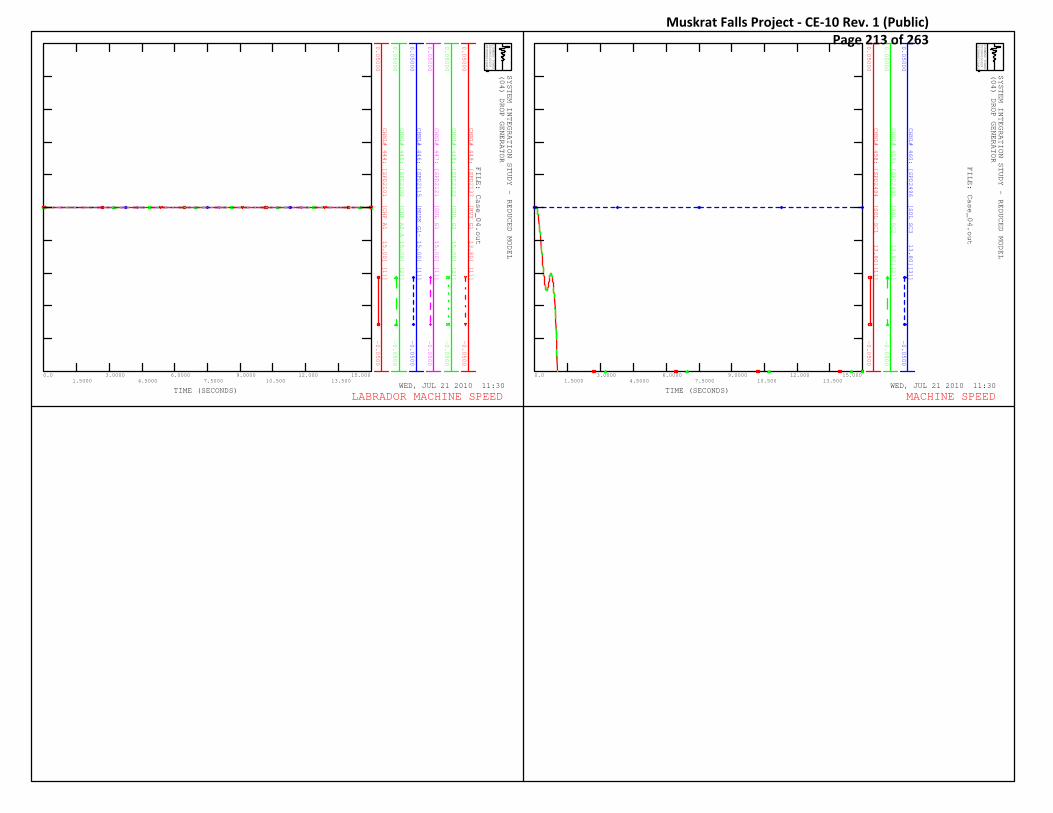
CHNL# 444: [SPD2101 [CHF A1 15.00] [1]]
0.05000
-0.0500
CHNL# 445: [SPD2102 [CHF A2-A 15.00] [2]]
0.05000
-0.0500
CHNL# 446: [SPD2115 [MUSK G1- 15.00] [1]]
0.05000
-0.0500
CHNL# 447: [SPD2121 [GUL G1 15.00] [1]]
0.05000
-0.0500
CHNL# 448: [SPD2122 [GUL G2 15.00] [2]]
0.05000
-0.0500
CHNL# 449: [SPD2137 [HVY G1 13.80] [1]]
0.05000
-0.0500
SYSTEM INTEGRATION STUDY - REDUCED MODEL
(04) DROP GENERATOR
WED, JUL 21 2010 11:30TIME (SECONDS)
SIEMENS POWER
TECHNOLOGIES
INTERNATIONAL
R
0.01.5000
3.00004.5000
6.00007.5000
9.000010.500
12.00013.500
15.000
FILE: Case_04.out
LABRADOR MACHINE SPEED
CHNL# 458: [SPD2494 [SOL SC1 13.80][1]]
0.05000
-0.0500
CHNL# 459: [SPD2495 [SOL SC2 13.80][2]]
0.05000
-0.0500
CHNL# 460: [SPD2496 [SOL SC3 13.80][3]]
0.05000
-0.0500
SYSTEM INTEGRATION STUDY - REDUCED MODEL
(04) DROP GENERATOR
WED, JUL 21 2010 11:30TIME (SECONDS)
SIEMENS POWER
TECHNOLOGIES
INTERNATIONAL
R
0.01.5000
3.00004.5000
6.00007.5000
9.000010.500
12.00013.500
15.000
FILE: Case_04.out
MACHINE SPEED
Muskrat Falls Project - CE-10 Rev. 1 (Public) Page 213 of 263

CHNL# 628: 60.0*(1+[FREQ153 [DPD L64 66]])
62.000
58.000
CHNL# 629: 60.0*(1+[FREQ204 [SVL B2 66]])
62.000
58.000
CHNL# 630: 60.0*(1+[FREQ308 [BLK NPT3 66]])
62.000
58.000
CHNL# 631: 60.0*(1+[FREQ309 [BRB T2T3 66]])
62.000
58.000
CHNL# 632: 60.0*(1+[FREQ319 [DLK NP 66]])
62.000
58.000
CHNL# 633: 60.0*(1+[FREQ334 [OPD B2B5 66]])
62.000
58.000
SYSTEM INTEGRATION STUDY - REDUCED MODEL
(04) DROP GENERATOR
WED, JUL 21 2010 11:30TIME (SECONDS)
SIEMENS POWER
TECHNOLOGIES
INTERNATIONAL
R
0.01.5000
3.00004.5000
6.00007.5000
9.000010.500
12.00013.500
15.000
FILE: Case_04.out
BUS FREQUENCY
CHNL# 634: 60.0*(1+[FREQ335 [HWD B7B8 66]])
62.000
58.000
CHNL# 635: 60.0*(1+[FREQ336 [WAV B2 66]])
62.000
58.000
CHNL# 636: 60.0*(1+[FREQ337 [HRD B6B7 66]])
62.000
58.000
CHNL# 637: 60.0*(1+[FREQ345 [ULT TAP 66]])
62.000
58.000
CHNL# 638: 60.0*(1+[FREQ346 [ULT NP 66]])
62.000
58.000
CHNL# 639: 60.0*(1+[FREQ347 [SCV NP 66]])
62.000
58.000
SYSTEM INTEGRATION STUDY - REDUCED MODEL
(04) DROP GENERATOR
WED, JUL 21 2010 11:30TIME (SECONDS)
SIEMENS POWER
TECHNOLOGIES
INTERNATIONAL
R
0.01.5000
3.00004.5000
6.00007.5000
9.000010.500
12.00013.500
15.000
FILE: Case_04.out
BUS FREQUENCY
CHNL# 640: 60.0*(1+[FREQ348 [KEL NP 66]])
62.000
58.000
CHNL# 641: 60.0*(1+[FREQ349 [CHA NP 66]])
62.000
58.000
CHNL# 642: 60.0*(1+[FREQ455 [GDL NP 66]])
62.000
58.000
CHNL# 643: 60.0*(1+[FREQ457 [GOU NP 66]])
62.000
58.000
CHNL# 646: 60.0*(1+[FREQ467 [TCV NP 66]])
62.000
58.000
CHNL# 652: 60.0*(1+[FREQ482 [MRP NP 66]])
62.000
58.000
SYSTEM INTEGRATION STUDY - REDUCED MODEL
(04) DROP GENERATOR
WED, JUL 21 2010 11:30TIME (SECONDS)
SIEMENS POWER
TECHNOLOGIES
INTERNATIONAL
R
0.01.5000
3.00004.5000
6.00007.5000
9.000010.500
12.00013.500
15.000
FILE: Case_04.out
BUS FREQUENCY
CHNL# 658: 60.0*(1+[FREQ550 [MOB NP 66]])
62.000
58.000
CHNL# 659: 60.0*(1+[FREQ558 [ROP NP 66]])
62.000
58.000
CHNL# 664: 60.0*(1+[FREQ973 [GOU MID1 66]])
62.000
58.000
CHNL# 665: 60.0*(1+[FREQ982 [CHA MID1 66]])
62.000
58.000
CHNL# 666: 60.0*(1+[FREQ111 [DLK B1 138]])
62.000
58.000
CHNL# 667: 60.0*(1+[FREQ112 [IRV B1 138]])
62.000
58.000
SYSTEM INTEGRATION STUDY - REDUCED MODEL
(04) DROP GENERATOR
WED, JUL 21 2010 11:30TIME (SECONDS)
SIEMENS POWER
TECHNOLOGIES
INTERNATIONAL
R
0.01.5000
3.00004.5000
6.00007.5000
9.000010.500
12.00013.500
15.000
FILE: Case_04.out
BUS FREQUENCY
Muskrat Falls Project - CE-10 Rev. 1 (Public) Page 214 of 263

CHNL# 668: 60.0*(1+[FREQ113 [SPL B1 138]])
62.000
58.000
CHNL# 669: 60.0*(1+[FREQ203 [BBK B2 138]])
62.000
58.000
CHNL# 670: 60.0*(1+[FREQ212 [HLY B1 138]])
62.000
58.000
CHNL# 671: 60.0*(1+[FREQ213 [HLK L43 138]])
62.000
58.000
CHNL# 672: 60.0*(1+[FREQ217 [STB B3 138]])
62.000
58.000
CHNL# 673: 60.0*(1+[FREQ219 [SOK L22 138]])
62.000
58.000
SYSTEM INTEGRATION STUDY - REDUCED MODEL
(04) DROP GENERATOR
WED, JUL 21 2010 11:30TIME (SECONDS)
SIEMENS POWER
TECHNOLOGIES
INTERNATIONAL
R
0.01.5000
3.00004.5000
6.00007.5000
9.000010.500
12.00013.500
15.000
FILE: Case_04.out
BUS FREQUENCY
CHNL# 674: 60.0*(1+[FREQ223 [SSD B2B3 138]])
62.000
58.000
CHNL# 675: 60.0*(1+[FREQ224 [BLA L12 138]])
62.000
58.000
CHNL# 676: 60.0*(1+[FREQ225 [LLK NP 138]])
62.000
58.000
CHNL# 677: 60.0*(1+[FREQ232 [MKS L12 138]])
62.000
58.000
CHNL# 678: 60.0*(1+[FREQ310 [BLK NP 138]])
62.000
58.000
CHNL# 679: 60.0*(1+[FREQ311 [WAV B4 138]])
62.000
58.000
SYSTEM INTEGRATION STUDY - REDUCED MODEL
(04) DROP GENERATOR
WED, JUL 21 2010 11:30TIME (SECONDS)
SIEMENS POWER
TECHNOLOGIES
INTERNATIONAL
R
0.01.5000
3.00004.5000
6.00007.5000
9.000010.500
12.00013.500
15.000
FILE: Case_04.out
BUS FREQUENCY
CHNL# 680: 60.0*(1+[FREQ338 [HRD B8 138]])
62.000
58.000
CHNL# 681: 60.0*(1+[FREQ340 [HOL NP 138]])
62.000
58.000
CHNL# 682: 60.0*(1+[FREQ353 [SPF NP 138]])
62.000
58.000
CHNL# 683: 60.0*(1+[FREQ354 [COL NP 138]])
62.000
58.000
CHNL# 684: 60.0*(1+[FREQ357 [BRB NP 138]])
62.000
58.000
CHNL# 685: 60.0*(1+[FREQ359 [MSY NP 138]])
62.000
58.000
SYSTEM INTEGRATION STUDY - REDUCED MODEL
(04) DROP GENERATOR
WED, JUL 21 2010 11:30TIME (SECONDS)
SIEMENS POWER
TECHNOLOGIES
INTERNATIONAL
R
0.01.5000
3.00004.5000
6.00007.5000
9.000010.500
12.00013.500
15.000
FILE: Case_04.out
BUS FREQUENCY
CHNL# 686: 60.0*(1+[FREQ371 [SPO NP 138]])
62.000
58.000
CHNL# 687: 60.0*(1+[FREQ603 [BBK B3 138]])
62.000
58.000
CHNL# 692: 60.0*(1+[FREQ205 [BBK B1 230]])
62.000
58.000
CHNL# 693: 60.0*(1+[FREQ206 [SVL B1 230]])
62.000
58.000
CHNL# 694: 60.0*(1+[FREQ208 [MDR B1B5 230]])
62.000
58.000
SYSTEM INTEGRATION STUDY - REDUCED MODEL
(04) DROP GENERATOR
WED, JUL 21 2010 11:30TIME (SECONDS)
SIEMENS POWER
TECHNOLOGIES
INTERNATIONAL
R
0.01.5000
3.00004.5000
6.00007.5000
9.000010.500
12.00013.500
15.000
FILE: Case_04.out
BUS FREQUENCY
Muskrat Falls Project - CE-10 Rev. 1 (Public) Page 215 of 263

CHNL# 696: 60.0*(1+[FREQ215 [BUC B1 230]])
62.000
58.000
CHNL# 697: 60.0*(1+[FREQ216 [STB B1B2 230]])
62.000
58.000
CHNL# 701: 60.0*(1+[FREQ227 [CBC B1B2 230]])
62.000
58.000
CHNL# 702: 60.0*(1+[FREQ229 [WAV B1B3 230]])
62.000
58.000
CHNL# 703: 60.0*(1+[FREQ230 [LHR B1 230]])
62.000
58.000
CHNL# 704: 60.0*(1+[FREQ234 [HRD TS 230]])
62.000
58.000
SYSTEM INTEGRATION STUDY - REDUCED MODEL
(04) DROP GENERATOR
WED, JUL 21 2010 11:30TIME (SECONDS)
SIEMENS POWER
TECHNOLOGIES
INTERNATIONAL
R
0.01.5000
3.00004.5000
6.00007.5000
9.000010.500
12.00013.500
15.000
FILE: Case_04.out
BUS FREQUENCY
CHNL# 705: 60.0*(1+[FREQ236 [HWD B1B2 230]])
62.000
58.000
CHNL# 706: 60.0*(1+[FREQ238 [OPD B1 230]])
62.000
58.000
CHNL# 708: 60.0*(1+[FREQ261 [ACG GFL 230]])
62.000
58.000
CHNL# 709: 60.0*(1+[FREQ291 [GCL L63 230]])
62.000
58.000
CHNL# 710: 60.0*(1+[FREQ405 [USL L34 230]])
62.000
58.000
CHNL# 711: 60.0*(1+[FREQ912 [TL202X 230]])
62.000
58.000
SYSTEM INTEGRATION STUDY - REDUCED MODEL
(04) DROP GENERATOR
WED, JUL 21 2010 11:30TIME (SECONDS)
SIEMENS POWER
TECHNOLOGIES
INTERNATIONAL
R
0.01.5000
3.00004.5000
6.00007.5000
9.000010.500
12.00013.500
15.000
FILE: Case_04.out
BUS FREQUENCY
CHNL# 712: 60.0*(1+[FREQ916 [TL206X 230]])
62.000
58.000
CHNL# 713: 60.0*(1+[FREQ918 [TLNEWX 230]])
62.000
58.000
CHNL# 714: 60.0*(1+[FREQ2181 [TL202Y 230]])
62.000
58.000
CHNL# 715: 60.0*(1+[FREQ2182 [TL206Y 230]])
62.000
58.000
CHNL# 716: 60.0*(1+[FREQ2183 [TLNEWY 230]])
62.000
58.000
CHNL# 726: 60.0*(1+[FREQ2490 [SOL B1 230]])
62.000
58.000
SYSTEM INTEGRATION STUDY - REDUCED MODEL
(04) DROP GENERATOR
WED, JUL 21 2010 11:30TIME (SECONDS)
SIEMENS POWER
TECHNOLOGIES
INTERNATIONAL
R
0.01.5000
3.00004.5000
6.00007.5000
9.000010.500
12.00013.500
15.000
FILE: Case_04.out
BUS FREQUENCY
CHNL# 717: 60.0*(1+[FREQ2301 [CHF A1 B 230]])
62.000
58.000
CHNL# 718: 60.0*(1+[FREQ2302 [CHF A2 & 230]])
62.000
58.000
CHNL# 719: 60.0*(1+[FREQ2307 [WABUSH T 230]])
62.000
58.000
CHNL# 720: 60.0*(1+[FREQ2308 [GUL 230 230]])
62.000
58.000
CHNL# 724: 60.0*(1+[FREQ2341 [GUL T1 230]])
62.000
58.000
CHNL# 725: 60.0*(1+[FREQ2342 [GUL T2 230]])
62.000
58.000
SYSTEM INTEGRATION STUDY - REDUCED MODEL
(04) DROP GENERATOR
WED, JUL 21 2010 11:30TIME (SECONDS)
SIEMENS POWER
TECHNOLOGIES
INTERNATIONAL
R
0.01.5000
3.00004.5000
6.00007.5000
9.000010.500
12.00013.500
15.000
FILE: Case_04.out
LABRADOR BUS FREQUENCY
Muskrat Falls Project - CE-10 Rev. 1 (Public) Page 216 of 263

CHNL# 470: [VOLT115 [MDR B2B3 66]]
1.2000
0.0
CHNL# 471: [VOLT151 [BUC B2 66]]
1.2000
0.0
CHNL# 472: [VOLT152 [MDR B4 66]]
1.2000
0.0
CHNL# 473: [VOLT153 [DPD L64 66]]
1.2000
0.0
CHNL# 474: [VOLT204 [SVL B2 66]]
1.2000
0.0
CHNL# 475: [VOLT308 [BLK NPT3 66]]
1.2000
0.0
SYSTEM INTEGRATION STUDY - REDUCED MODEL
(04) DROP GENERATOR
WED, JUL 21 2010 11:30TIME (SECONDS)
SIEMENS POWER
TECHNOLOGIES
INTERNATIONAL
R
0.01.5000
3.00004.5000
6.00007.5000
9.000010.500
12.00013.500
15.000
FILE: Case_04.out
VOLTAGE
CHNL# 476: [VOLT309 [BRB T2T3 66]]
1.2000
0.0
CHNL# 477: [VOLT319 [DLK NP 66]]
1.2000
0.0
CHNL# 478: [VOLT334 [OPD B2B5 66]]
1.2000
0.0
CHNL# 479: [VOLT335 [HWD B7B8 66]]
1.2000
0.0
CHNL# 480: [VOLT336 [WAV B2 66]]
1.2000
0.0
CHNL# 481: [VOLT337 [HRD B6B7 66]]
1.2000
0.0
SYSTEM INTEGRATION STUDY - REDUCED MODEL
(04) DROP GENERATOR
WED, JUL 21 2010 11:30TIME (SECONDS)
SIEMENS POWER
TECHNOLOGIES
INTERNATIONAL
R
0.01.5000
3.00004.5000
6.00007.5000
9.000010.500
12.00013.500
15.000
FILE: Case_04.out
VOLTAGE
CHNL# 482: [VOLT345 [ULT TAP 66]]
1.2000
0.0
CHNL# 483: [VOLT346 [ULT NP 66]]
1.2000
0.0
CHNL# 484: [VOLT347 [SCV NP 66]]
1.2000
0.0
CHNL# 485: [VOLT348 [KEL NP 66]]
1.2000
0.0
CHNL# 486: [VOLT349 [CHA NP 66]]
1.2000
0.0
CHNL# 487: [VOLT455 [GDL NP 66]]
1.2000
0.0
SYSTEM INTEGRATION STUDY - REDUCED MODEL
(04) DROP GENERATOR
WED, JUL 21 2010 11:30TIME (SECONDS)
SIEMENS POWER
TECHNOLOGIES
INTERNATIONAL
R
0.01.5000
3.00004.5000
6.00007.5000
9.000010.500
12.00013.500
15.000
FILE: Case_04.out
VOLTAGE
CHNL# 488: [VOLT457 [GOU NP 66]]
1.2000
0.0
CHNL# 489: [VOLT463 [KEN NP 66]]
1.2000
0.0
CHNL# 490: [VOLT466 [KBR NP 66]]
1.2000
0.0
CHNL# 491: [VOLT467 [TCV NP 66]]
1.2000
0.0
CHNL# 492: [VOLT469 [MUN NP 66]]
1.2000
0.0
CHNL# 493: [VOLT471 [MOL NP 66]]
1.2000
0.0
SYSTEM INTEGRATION STUDY - REDUCED MODEL
(04) DROP GENERATOR
WED, JUL 21 2010 11:30TIME (SECONDS)
SIEMENS POWER
TECHNOLOGIES
INTERNATIONAL
R
0.01.5000
3.00004.5000
6.00007.5000
9.000010.500
12.00013.500
15.000
FILE: Case_04.out
VOLTAGE
Muskrat Falls Project - CE-10 Rev. 1 (Public) Page 217 of 263

CHNL# 494: [VOLT474 [PEP NP 66]]
1.2000
0.0
CHNL# 495: [VOLT479 [PUL NP 66]]
1.2000
0.0
CHNL# 496: [VOLT481 [RRD NP 66]]
1.2000
0.0
CHNL# 497: [VOLT482 [MRP NP 66]]
1.2000
0.0
CHNL# 498: [VOLT484 [SJM NP 66]]
1.2000
0.0
CHNL# 499: [VOLT485 [HCP NP 66]]
1.2000
0.0
SYSTEM INTEGRATION STUDY - REDUCED MODEL
(04) DROP GENERATOR
WED, JUL 21 2010 11:30TIME (SECONDS)
SIEMENS POWER
TECHNOLOGIES
INTERNATIONAL
R
0.01.5000
3.00004.5000
6.00007.5000
9.000010.500
12.00013.500
15.000
FILE: Case_04.out
VOLTAGE
CHNL# 500: [VOLT489 [SLA NP 66]]
1.2000
0.0
CHNL# 501: [VOLT492 [VIR NP 66]]
1.2000
0.0
CHNL# 502: [VOLT510 [BIG NP 66]]
1.2000
0.0
CHNL# 503: [VOLT550 [MOB NP 66]]
1.2000
0.0
CHNL# 504: [VOLT558 [ROP NP 66]]
1.2000
0.0
CHNL# 505: [VOLT576 [CAB NP 66]]
1.2000
0.0
SYSTEM INTEGRATION STUDY - REDUCED MODEL
(04) DROP GENERATOR
WED, JUL 21 2010 11:30TIME (SECONDS)
SIEMENS POWER
TECHNOLOGIES
INTERNATIONAL
R
0.01.5000
3.00004.5000
6.00007.5000
9.000010.500
12.00013.500
15.000
FILE: Case_04.out
VOLTAGE
CHNL# 506: [VOLT579 [FER NP 66]]
1.2000
0.0
CHNL# 507: [VOLT870 [SLK L80 66]]
1.2000
0.0
CHNL# 508: [VOLT920 [MOB MID3 66]]
1.2000
0.0
CHNL# 509: [VOLT973 [GOU MID1 66]]
1.2000
0.0
CHNL# 510: [VOLT982 [CHA MID1 66]]
1.2000
0.0
CHNL# 511: [VOLT111 [DLK B1 138]]
1.2000
0.0
SYSTEM INTEGRATION STUDY - REDUCED MODEL
(04) DROP GENERATOR
WED, JUL 21 2010 11:30TIME (SECONDS)
SIEMENS POWER
TECHNOLOGIES
INTERNATIONAL
R
0.01.5000
3.00004.5000
6.00007.5000
9.000010.500
12.00013.500
15.000
FILE: Case_04.out
VOLTAGE
CHNL# 512: [VOLT112 [IRV B1 138]]
1.2000
0.0
CHNL# 513: [VOLT113 [SPL B1 138]]
1.2000
0.0
CHNL# 514: [VOLT203 [BBK B2 138]]
1.2000
0.0
CHNL# 515: [VOLT212 [HLY B1 138]]
1.2000
0.0
CHNL# 516: [VOLT213 [HLK L43 138]]
1.2000
0.0
CHNL# 517: [VOLT217 [STB B3 138]]
1.2000
0.0
SYSTEM INTEGRATION STUDY - REDUCED MODEL
(04) DROP GENERATOR
WED, JUL 21 2010 11:30TIME (SECONDS)
SIEMENS POWER
TECHNOLOGIES
INTERNATIONAL
R
0.01.5000
3.00004.5000
6.00007.5000
9.000010.500
12.00013.500
15.000
FILE: Case_04.out
VOLTAGE
Muskrat Falls Project - CE-10 Rev. 1 (Public) Page 218 of 263

CHNL# 518: [VOLT219 [SOK L22 138]]
1.2000
0.0
CHNL# 519: [VOLT223 [SSD B2B3 138]]
1.2000
0.0
CHNL# 520: [VOLT224 [BLA L12 138]]
1.2000
0.0
CHNL# 521: [VOLT225 [LLK NP 138]]
1.2000
0.0
CHNL# 522: [VOLT232 [MKS L12 138]]
1.2000
0.0
CHNL# 523: [VOLT310 [BLK NP 138]]
1.2000
0.0
SYSTEM INTEGRATION STUDY - REDUCED MODEL
(04) DROP GENERATOR
WED, JUL 21 2010 11:30TIME (SECONDS)
SIEMENS POWER
TECHNOLOGIES
INTERNATIONAL
R
0.01.5000
3.00004.5000
6.00007.5000
9.000010.500
12.00013.500
15.000
FILE: Case_04.out
VOLTAGE
CHNL# 524: [VOLT311 [WAV B4 138]]
1.2000
0.0
CHNL# 525: [VOLT338 [HRD B8 138]]
1.2000
0.0
CHNL# 526: [VOLT340 [HOL NP 138]]
1.2000
0.0
CHNL# 527: [VOLT353 [SPF NP 138]]
1.2000
0.0
CHNL# 528: [VOLT354 [COL NP 138]]
1.2000
0.0
CHNL# 529: [VOLT357 [BRB NP 138]]
1.2000
0.0
SYSTEM INTEGRATION STUDY - REDUCED MODEL
(04) DROP GENERATOR
WED, JUL 21 2010 11:30TIME (SECONDS)
SIEMENS POWER
TECHNOLOGIES
INTERNATIONAL
R
0.01.5000
3.00004.5000
6.00007.5000
9.000010.500
12.00013.500
15.000
FILE: Case_04.out
VOLTAGE
CHNL# 530: [VOLT359 [MSY NP 138]]
1.2000
0.0
CHNL# 531: [VOLT371 [SPO NP 138]]
1.2000
0.0
CHNL# 532: [VOLT603 [BBK B3 138]]
1.2000
0.0
SYSTEM INTEGRATION STUDY - REDUCED MODEL
(04) DROP GENERATOR
WED, JUL 21 2010 11:30TIME (SECONDS)
SIEMENS POWER
TECHNOLOGIES
INTERNATIONAL
R
0.01.5000
3.00004.5000
6.00007.5000
9.000010.500
12.00013.500
15.000
FILE: Case_04.out
VOLTAGE
CHNL# 536: [VOLT136 [CAT L47 230]]
1.2000
0.0
CHNL# 537: [VOLT205 [BBK B1 230]]
1.2000
0.0
CHNL# 538: [VOLT206 [SVL B1 230]]
1.2000
0.0
CHNL# 539: [VOLT208 [MDR B1B5 230]]
1.2000
0.0
CHNL# 540: [VOLT211 [NLREFINE 230]]
1.2000
0.0
SYSTEM INTEGRATION STUDY - REDUCED MODEL
(04) DROP GENERATOR
WED, JUL 21 2010 11:30TIME (SECONDS)
SIEMENS POWER
TECHNOLOGIES
INTERNATIONAL
R
0.01.5000
3.00004.5000
6.00007.5000
9.000010.500
12.00013.500
15.000
FILE: Case_04.out
VOLTAGE
Muskrat Falls Project - CE-10 Rev. 1 (Public) Page 219 of 263
CHNL# 543: [VOLT218 [PIPERS_H 230]]
1.2000
0.0
CHNL# 544: [VOLT221 [BDE TS 230]]
1.2000
0.0
CHNL# 545: [VOLT222 [SSD B1 230]]
1.2000
0.0
CHNL# 546: [VOLT227 [CBC B1B2 230]]
1.2000
0.0
CHNL# 547: [VOLT229 [WAV B1B3 230]]
1.2000
0.0
SYSTEM INTEGRATION STUDY - REDUCED MODEL
(04) DROP GENERATOR
WED, JUL 21 2010 11:30TIME (SECONDS)
SIEMENS POWER
TECHNOLOGIES
INTERNATIONAL
R
0.01.5000
3.00004.5000
6.00007.5000
9.000010.500
12.00013.500
15.000
FILE: Case_04.out
VOLTAGE
CHNL# 548: [VOLT230 [LHR B1 230]]
1.2000
0.0
CHNL# 549: [VOLT234 [HRD TS 230]]
1.2000
0.0
CHNL# 550: [VOLT236 [HWD B1B2 230]]
1.2000
0.0
CHNL# 551: [VOLT238 [OPD B1 230]]
1.2000
0.0
CHNL# 552: [VOLT260 [ACS SVL 230]]
1.2000
0.0
SYSTEM INTEGRATION STUDY - REDUCED MODEL
(04) DROP GENERATOR
WED, JUL 21 2010 11:30TIME (SECONDS)
SIEMENS POWER
TECHNOLOGIES
INTERNATIONAL
R
0.01.5000
3.00004.5000
6.00007.5000
9.000010.500
12.00013.500
15.000
FILE: Case_04.out
VOLTAGE
CHNL# 553: [VOLT261 [ACG GFL 230]]
1.2000
0.0
CHNL# 554: [VOLT291 [GCL L63 230]]
1.2000
0.0
CHNL# 555: [VOLT405 [USL L34 230]]
1.2000
0.0
CHNL# 556: [VOLT912 [TL202X 230]]
1.2000
0.0
CHNL# 557: [VOLT916 [TL206X 230]]
1.2000
0.0
SYSTEM INTEGRATION STUDY - REDUCED MODEL
(04) DROP GENERATOR
WED, JUL 21 2010 11:30TIME (SECONDS)
SIEMENS POWER
TECHNOLOGIES
INTERNATIONAL
R
0.01.5000
3.00004.5000
6.00007.5000
9.000010.500
12.00013.500
15.000
FILE: Case_04.out
VOLTAGE
CHNL# 558: [VOLT918 [TLNEWX 230]]
1.2000
0.0
CHNL# 559: [VOLT2181 [TL202Y 230]]
1.2000
0.0
CHNL# 560: [VOLT2182 [TL206Y 230]]
1.2000
0.0
CHNL# 561: [VOLT2183 [TLNEWY 230]]
1.2000
0.0
SYSTEM INTEGRATION STUDY - REDUCED MODEL
(04) DROP GENERATOR
WED, JUL 21 2010 11:30TIME (SECONDS)
SIEMENS POWER
TECHNOLOGIES
INTERNATIONAL
R
0.01.5000
3.00004.5000
6.00007.5000
9.000010.500
12.00013.500
15.000
FILE: Case_04.out
VOLTAGE
Muskrat Falls Project - CE-10 Rev. 1 (Public) Page 220 of 263

CHNL# 61: [ANGL2490 [SOL B1 230.00][1]]
500.00
-500.0
CHNL# 457: [SPD2490 [SOL B1 230.00][1]]
0.50000
-0.5000
SYSTEM INTEGRATION STUDY - REDUCED MODEL
(04) DROP GENERATOR
WED, MAR 03 2010 8:56TIME (SECONDS)
SIEMENS POWER
TECHNOLOGIES
INTERNATIONAL
R
0.01.5000
3.00004.5000
6.00007.5000
9.000010.500
12.00013.500
15.000
FILE: Case_04.out
MACHINE BUS 2490
CHNL# 127: 100*[POWR2490 [SOL B1 230.00][1]]
50.000
-50.00
CHNL# 193: 100*[VARS2490 [SOL B1 230.00][1]]
50.000
-50.00
SYSTEM INTEGRATION STUDY - REDUCED MODEL
(04) DROP GENERATOR
WED, MAR 03 2010 8:56TIME (SECONDS)
SIEMENS POWER
TECHNOLOGIES
INTERNATIONAL
R
0.01.5000
3.00004.5000
6.00007.5000
9.000010.500
12.00013.500
15.000
FILE: Case_04.out
MACHINE BUS 2490
CHNL# 773: 100*[SOLP_P1_MW]
100.00
-400.0
CHNL# 775: 100*[SOLP_P2_MW]
100.00
-400.0
SYSTEM INTEGRATION STUDY - REDUCED MODEL
(04) DROP GENERATOR
WED, MAR 03 2010 8:56TIME (SECONDS)
SIEMENS POWER
TECHNOLOGIES
INTERNATIONAL
R
0.01.5000
3.00004.5000
6.00007.5000
9.000010.500
12.00013.500
15.000
FILE: Case_04.out
HVDC, MW
CHNL# 774: 100*[SOLP_P2_MVAR]
400.00
-100.0
CHNL# 776: 100*[SOLP_P2_MVAR]
400.00
-100.0
SYSTEM INTEGRATION STUDY - REDUCED MODEL
(04) DROP GENERATOR
WED, MAR 03 2010 8:56TIME (SECONDS)
SIEMENS POWER
TECHNOLOGIES
INTERNATIONAL
R
0.01.5000
3.00004.5000
6.00007.5000
9.000010.500
12.00013.500
15.000
FILE: Case_04.out
HVDC, MVAR
Muskrat Falls Project - CE-10 Rev. 1 (Public) Page 221 of 263

CHNL# 1: [ANGL21 [ACG 1P2P 6.90] [1]]
500.00
-1000.
CHNL# 2: [ANGL21 [ACG 1P2P 6.90] [2]]
500.00
-1000.
CHNL# 3: [ANGL23 [ACG 3P4P 6.90] [1]]
500.00
-1000.
CHNL# 4: [ANGL23 [ACG 3P4P 6.90] [2]]
500.00
-1000.
CHNL# 5: [ANGL24 [ACG G7G8 6.90] [1]]
500.00
-1000.
SYSTEM INTEGRATION STUDY - REDUCED MODEL
(05) DROP GENERATOR
WED, JUL 21 2010 11:30TIME (SECONDS)
SIEMENS POWER
TECHNOLOGIES
INTERNATIONAL
R
0.01.5000
3.00004.5000
6.00007.5000
9.000010.500
12.00013.500
15.000
FILE: Case_05.out
ROTOR ANGLES
CHNL# 6: [ANGL24 [ACG G7G8 6.90] [2]]
500.00
-1000.
CHNL# 7: [ANGL25 [ACG G5G6 6.90] [1]]
500.00
-1000.
CHNL# 8: [ANGL25 [ACG G5G6 6.90] [2]]
500.00
-1000.
CHNL# 9: [ANGL29 [ACGBG1-9 6.90] [1]]
500.00
-1000.
CHNL# 10: [ANGL33 [ACG G4 6.90] [1]]
500.00
-1000.
SYSTEM INTEGRATION STUDY - REDUCED MODEL
(05) DROP GENERATOR
WED, JUL 21 2010 11:30TIME (SECONDS)
SIEMENS POWER
TECHNOLOGIES
INTERNATIONAL
R
0.01.5000
3.00004.5000
6.00007.5000
9.000010.500
12.00013.500
15.000
FILE: Case_05.out
ROTOR ANGLES
CHNL# 11: [ANGL34 [ACG G9 13.80] [1]]
500.00
-1000.
CHNL# 12: [ANGL105 [CBF CBPP 6.60] [1]]
500.00
-1000.
CHNL# 13: [ANGL109 [DLP G1-7 6.00] [1]]
500.00
-1000.
CHNL# 14: [ANGL137 [CAT G1 13.80] [1]]
500.00
-1000.
CHNL# 15: [ANGL138 [CAT G2 13.80] [1]]
500.00
-1000.
SYSTEM INTEGRATION STUDY - REDUCED MODEL
(05) DROP GENERATOR
WED, JUL 21 2010 11:30TIME (SECONDS)
SIEMENS POWER
TECHNOLOGIES
INTERNATIONAL
R
0.01.5000
3.00004.5000
6.00007.5000
9.000010.500
12.00013.500
15.000
FILE: Case_05.out
ROTOR ANGLES
CHNL# 16: [ANGL209 [SVL G1 13.80] [1]]
500.00
-1000.
CHNL# 17: [ANGL220 [BDP G2-6 13.80] [2]]
500.00
-1000.
CHNL# 18: [ANGL220 [BDP G2-6 13.80] [3]]
500.00
-1000.
CHNL# 19: [ANGL220 [BDP G2-6 13.80] [4]]
500.00
-1000.
CHNL# 20: [ANGL220 [BDP G2-6 13.80] [5]]
500.00
-1000.
SYSTEM INTEGRATION STUDY - REDUCED MODEL
(05) DROP GENERATOR
WED, JUL 21 2010 11:30TIME (SECONDS)
SIEMENS POWER
TECHNOLOGIES
INTERNATIONAL
R
0.01.5000
3.00004.5000
6.00007.5000
9.000010.500
12.00013.500
15.000
FILE: Case_05.out
ROTOR ANGLES
Muskrat Falls Project - CE-10 Rev. 1 (Public) Page 222 of 263
CHNL# 21: [ANGL220 [BDP G2-6 13.80] [6]]
500.00
-1000.
CHNL# 23: [ANGL237 [HWD G1 13.80] [1]]
500.00
-1000.
CHNL# 24: [ANGL250 [HLK G1 13.80] [1]]
500.00
-1000.
SYSTEM INTEGRATION STUDY - REDUCED MODEL
(05) DROP GENERATOR
WED, JUL 21 2010 11:30TIME (SECONDS)
SIEMENS POWER
TECHNOLOGIES
INTERNATIONAL
R
0.01.5000
3.00004.5000
6.00007.5000
9.000010.500
12.00013.500
15.000
FILE: Case_05.out
ROTOR ANGLES
CHNL# 25: [ANGL284 [PRV G1 4.20] [1]]
500.00
-1000.
CHNL# 26: [ANGL290 [GCL G1 13.80] [1]]
500.00
-1000.
CHNL# 27: [ANGL352 [SCV GEN 2.40] [1]]
500.00
-1000.
CHNL# 28: [ANGL352 [SCV GEN 2.40] [2]]
500.00
-1000.
SYSTEM INTEGRATION STUDY - REDUCED MODEL
(05) DROP GENERATOR
WED, JUL 21 2010 11:30TIME (SECONDS)
SIEMENS POWER
TECHNOLOGIES
INTERNATIONAL
R
0.01.5000
3.00004.5000
6.00007.5000
9.000010.500
12.00013.500
15.000
FILE: Case_05.out
ROTOR ANGLES
CHNL# 29: [ANGL406 [USL G1 13.80] [1]]
500.00
-1000.
CHNL# 30: [ANGL434 [HRP G1&G 16.00] [1]]
500.00
-1000.
CHNL# 31: [ANGL436 [HRP G3 16.00] [1]]
500.00
-1000.
SYSTEM INTEGRATION STUDY - REDUCED MODEL
(05) DROP GENERATOR
WED, JUL 21 2010 11:30TIME (SECONDS)
SIEMENS POWER
TECHNOLOGIES
INTERNATIONAL
R
0.01.5000
3.00004.5000
6.00007.5000
9.000010.500
12.00013.500
15.000
FILE: Case_05.out
ROTOR ANGLES
CHNL# 33: [ANGL454 [TOP GEN 2.40] [1]]
500.00
-1000.
CHNL# 34: [ANGL457 [GOU NP 66.00] [1]]
500.00
-1000.
CHNL# 35: [ANGL464 [PBK G1 6.90] [1]]
500.00
-1000.
CHNL# 36: [ANGL465 [MOB NP G 6.90] [1]]
500.00
-1000.
CHNL# 37: [ANGL468 [TCV GEN 6.90] [1]]
500.00
-1000.
SYSTEM INTEGRATION STUDY - REDUCED MODEL
(05) DROP GENERATOR
WED, JUL 21 2010 11:30TIME (SECONDS)
SIEMENS POWER
TECHNOLOGIES
INTERNATIONAL
R
0.01.5000
3.00004.5000
6.00007.5000
9.000010.500
12.00013.500
15.000
FILE: Case_05.out
ROTOR ANGLES
Muskrat Falls Project - CE-10 Rev. 1 (Public) Page 223 of 263

CHNL# 38: [ANGL468 [TCV GEN 6.90] [2]]
500.00
-1000.
CHNL# 39: [ANGL468 [TCV GEN 6.90] [3]]
500.00
-1000.
CHNL# 40: [ANGL473 [ROP G1 6.90] [1]]
500.00
-1000.
CHNL# 41: [ANGL478 [PHR GEN 2.30] [1]]
500.00
-1000.
CHNL# 42: [ANGL478 [PHR GEN 2.30] [2]]
500.00
-1000.
CHNL# 43: [ANGL478 [PHR GEN 2.30] [3]]
500.00
-1000.
SYSTEM INTEGRATION STUDY - REDUCED MODEL
(05) DROP GENERATOR
WED, JUL 21 2010 11:30TIME (SECONDS)
SIEMENS POWER
TECHNOLOGIES
INTERNATIONAL
R
0.01.5000
3.00004.5000
6.00007.5000
9.000010.500
12.00013.500
15.000
FILE: Case_05.out
ROTOR ANGLES
CHNL# 44: [ANGL483 [MRP G1 2.40] [1]]
500.00
-1000.
CHNL# 45: [ANGL486 [HCP G1 6.90] [1]]
500.00
-1000.
CHNL# 46: [ANGL488 [CAB G1 6.90] [1]]
500.00
-1000.
CHNL# 47: [ANGL871 [SLK G1 13.80] [1]]
500.00
-1000.
SYSTEM INTEGRATION STUDY - REDUCED MODEL
(05) DROP GENERATOR
WED, JUL 21 2010 11:30TIME (SECONDS)
SIEMENS POWER
TECHNOLOGIES
INTERNATIONAL
R
0.01.5000
3.00004.5000
6.00007.5000
9.000010.500
12.00013.500
15.000
FILE: Case_05.out
ROTOR ANGLES
CHNL# 56: [ANGL2201 [BDP G1 13.80][1]]
500.00
-1000.
CHNL# 57: [ANGL2207 [BDP G7 13.80][7]]
500.00
-1000.
CHNL# 58: [ANGL2221 [PHL SC1 13.80][1]]
500.00
-1000.
CHNL# 59: [ANGL2222 [PHL SC2 13.80][1]]
500.00
-1000.
SYSTEM INTEGRATION STUDY - REDUCED MODEL
(05) DROP GENERATOR
WED, JUL 21 2010 11:30TIME (SECONDS)
SIEMENS POWER
TECHNOLOGIES
INTERNATIONAL
R
0.01.5000
3.00004.5000
6.00007.5000
9.000010.500
12.00013.500
15.000
FILE: Case_05.out
ROTOR ANGLES
CHNL# 62: [ANGL2494 [SOL SC1 13.80][1]]
500.00
-1000.
CHNL# 63: [ANGL2495 [SOL SC2 13.80][2]]
500.00
-1000.
CHNL# 64: [ANGL2496 [SOL SC3 13.80][3]]
500.00
-1000.
SYSTEM INTEGRATION STUDY - REDUCED MODEL
(05) DROP GENERATOR
WED, JUL 21 2010 11:30TIME (SECONDS)
SIEMENS POWER
TECHNOLOGIES
INTERNATIONAL
R
0.01.5000
3.00004.5000
6.00007.5000
9.000010.500
12.00013.500
15.000
FILE: Case_05.out
ROTOR ANGLES
Muskrat Falls Project - CE-10 Rev. 1 (Public) Page 224 of 263

CHNL# 397: [SPD21 [ACG 1P2P 6.90] [1]]
0.05000
-0.0500
CHNL# 398: [SPD21 [ACG 1P2P 6.90] [2]]
0.05000
-0.0500
CHNL# 399: [SPD23 [ACG 3P4P 6.90] [1]]
0.05000
-0.0500
CHNL# 400: [SPD23 [ACG 3P4P 6.90] [2]]
0.05000
-0.0500
CHNL# 401: [SPD24 [ACG G7G8 6.90] [1]]
0.05000
-0.0500
CHNL# 402: [SPD24 [ACG G7G8 6.90] [2]]
0.05000
-0.0500
SYSTEM INTEGRATION STUDY - REDUCED MODEL
(05) DROP GENERATOR
WED, JUL 21 2010 11:31TIME (SECONDS)
SIEMENS POWER
TECHNOLOGIES
INTERNATIONAL
R
0.01.5000
3.00004.5000
6.00007.5000
9.000010.500
12.00013.500
15.000
FILE: Case_05.out
MACHINE SPEED
CHNL# 403: [SPD25 [ACG G5G6 6.90] [1]]
0.05000
-0.0500
CHNL# 404: [SPD25 [ACG G5G6 6.90] [2]]
0.05000
-0.0500
CHNL# 405: [SPD29 [ACGBG1-9 6.90] [1]]
0.05000
-0.0500
CHNL# 406: [SPD33 [ACG G4 6.90] [1]]
0.05000
-0.0500
CHNL# 407: [SPD34 [ACG G9 13.80] [1]]
0.05000
-0.0500
CHNL# 408: [SPD105 [CBF CBPP 6.60] [1]]
0.05000
-0.0500
SYSTEM INTEGRATION STUDY - REDUCED MODEL
(05) DROP GENERATOR
WED, JUL 21 2010 11:31TIME (SECONDS)
SIEMENS POWER
TECHNOLOGIES
INTERNATIONAL
R
0.01.5000
3.00004.5000
6.00007.5000
9.000010.500
12.00013.500
15.000
FILE: Case_05.out
MACHINE SPEED
CHNL# 409: [SPD109 [DLP G1-7 6.00] [1]]
0.05000
-0.0500
CHNL# 410: [SPD137 [CAT G1 13.80] [1]]
0.05000
-0.0500
CHNL# 411: [SPD138 [CAT G2 13.80] [1]]
0.05000
-0.0500
CHNL# 412: [SPD209 [SVL G1 13.80] [1]]
0.05000
-0.0500
CHNL# 413: [SPD220 [BDP G2-6 13.80] [2]]
0.05000
-0.0500
CHNL# 414: [SPD220 [BDP G2-6 13.80] [3]]
0.05000
-0.0500
SYSTEM INTEGRATION STUDY - REDUCED MODEL
(05) DROP GENERATOR
WED, JUL 21 2010 11:31TIME (SECONDS)
SIEMENS POWER
TECHNOLOGIES
INTERNATIONAL
R
0.01.5000
3.00004.5000
6.00007.5000
9.000010.500
12.00013.500
15.000
FILE: Case_05.out
MACHINE SPEED
CHNL# 415: [SPD220 [BDP G2-6 13.80] [4]]
0.05000
-0.0500
CHNL# 416: [SPD220 [BDP G2-6 13.80] [5]]
0.05000
-0.0500
CHNL# 417: [SPD220 [BDP G2-6 13.80] [6]]
0.05000
-0.0500
CHNL# 419: [SPD237 [HWD G1 13.80] [1]]
0.05000
-0.0500
CHNL# 420: [SPD250 [HLK G1 13.80] [1]]
0.05000
-0.0500
SYSTEM INTEGRATION STUDY - REDUCED MODEL
(05) DROP GENERATOR
WED, JUL 21 2010 11:31TIME (SECONDS)
SIEMENS POWER
TECHNOLOGIES
INTERNATIONAL
R
0.01.5000
3.00004.5000
6.00007.5000
9.000010.500
12.00013.500
15.000
FILE: Case_05.out
MACHINE SPEED
Muskrat Falls Project - CE-10 Rev. 1 (Public) Page 225 of 263

CHNL# 421: [SPD284 [PRV G1 4.20] [1]]
0.05000
-0.0500
CHNL# 422: [SPD290 [GCL G1 13.80] [1]]
0.05000
-0.0500
CHNL# 423: [SPD352 [SCV GEN 2.40] [1]]
0.05000
-0.0500
CHNL# 424: [SPD352 [SCV GEN 2.40] [2]]
0.05000
-0.0500
CHNL# 425: [SPD406 [USL G1 13.80] [1]]
0.05000
-0.0500
CHNL# 426: [SPD434 [HRP G1&G 16.00] [1]]
0.05000
-0.0500
SYSTEM INTEGRATION STUDY - REDUCED MODEL
(05) DROP GENERATOR
WED, JUL 21 2010 11:31TIME (SECONDS)
SIEMENS POWER
TECHNOLOGIES
INTERNATIONAL
R
0.01.5000
3.00004.5000
6.00007.5000
9.000010.500
12.00013.500
15.000
FILE: Case_05.out
MACHINE SPEED
CHNL# 427: [SPD436 [HRP G3 16.00] [1]]
0.05000
-0.0500
CHNL# 429: [SPD454 [TOP GEN 2.40] [1]]
0.05000
-0.0500
CHNL# 430: [SPD457 [GOU NP 66.00] [1]]
0.05000
-0.0500
CHNL# 431: [SPD464 [PBK G1 6.90] [1]]
0.05000
-0.0500
CHNL# 432: [SPD465 [MOB NP G 6.90] [1]]
0.05000
-0.0500
SYSTEM INTEGRATION STUDY - REDUCED MODEL
(05) DROP GENERATOR
WED, JUL 21 2010 11:31TIME (SECONDS)
SIEMENS POWER
TECHNOLOGIES
INTERNATIONAL
R
0.01.5000
3.00004.5000
6.00007.5000
9.000010.500
12.00013.500
15.000
FILE: Case_05.out
MACHINE SPEED
CHNL# 433: [SPD468 [TCV GEN 6.90] [1]]
0.05000
-0.0500
CHNL# 434: [SPD468 [TCV GEN 6.90] [2]]
0.05000
-0.0500
CHNL# 435: [SPD468 [TCV GEN 6.90] [3]]
0.05000
-0.0500
CHNL# 436: [SPD473 [ROP G1 6.90] [1]]
0.05000
-0.0500
CHNL# 437: [SPD478 [PHR GEN 2.30] [1]]
0.05000
-0.0500
CHNL# 438: [SPD478 [PHR GEN 2.30] [2]]
0.05000
-0.0500
SYSTEM INTEGRATION STUDY - REDUCED MODEL
(05) DROP GENERATOR
WED, JUL 21 2010 11:31TIME (SECONDS)
SIEMENS POWER
TECHNOLOGIES
INTERNATIONAL
R
0.01.5000
3.00004.5000
6.00007.5000
9.000010.500
12.00013.500
15.000
FILE: Case_05.out
MACHINE SPEED
CHNL# 439: [SPD478 [PHR GEN 2.30] [3]]
0.05000
-0.0500
CHNL# 440: [SPD483 [MRP G1 2.40] [1]]
0.05000
-0.0500
CHNL# 441: [SPD486 [HCP G1 6.90] [1]]
0.05000
-0.0500
CHNL# 442: [SPD488 [CAB G1 6.90] [1]]
0.05000
-0.0500
CHNL# 443: [SPD871 [SLK G1 13.80] [1]]
0.05000
-0.0500
SYSTEM INTEGRATION STUDY - REDUCED MODEL
(05) DROP GENERATOR
WED, JUL 21 2010 11:31TIME (SECONDS)
SIEMENS POWER
TECHNOLOGIES
INTERNATIONAL
R
0.01.5000
3.00004.5000
6.00007.5000
9.000010.500
12.00013.500
15.000
FILE: Case_05.out
MACHINE SPEED
Muskrat Falls Project - CE-10 Rev. 1 (Public) Page 226 of 263

CHNL# 444: [SPD2101 [CHF A1 15.00] [1]]
0.05000
-0.0500
CHNL# 445: [SPD2102 [CHF A2-A 15.00] [2]]
0.05000
-0.0500
CHNL# 446: [SPD2115 [MUSK G1- 15.00] [1]]
0.05000
-0.0500
CHNL# 447: [SPD2121 [GUL G1 15.00] [1]]
0.05000
-0.0500
CHNL# 448: [SPD2122 [GUL G2 15.00] [2]]
0.05000
-0.0500
CHNL# 449: [SPD2137 [HVY G1 13.80] [1]]
0.05000
-0.0500
SYSTEM INTEGRATION STUDY - REDUCED MODEL
(05) DROP GENERATOR
WED, JUL 21 2010 11:31TIME (SECONDS)
SIEMENS POWER
TECHNOLOGIES
INTERNATIONAL
R
0.01.5000
3.00004.5000
6.00007.5000
9.000010.500
12.00013.500
15.000
FILE: Case_05.out
LABRADOR MACHINE SPEED
CHNL# 458: [SPD2494 [SOL SC1 13.80][1]]
0.05000
-0.0500
CHNL# 459: [SPD2495 [SOL SC2 13.80][2]]
0.05000
-0.0500
CHNL# 460: [SPD2496 [SOL SC3 13.80][3]]
0.05000
-0.0500
SYSTEM INTEGRATION STUDY - REDUCED MODEL
(05) DROP GENERATOR
WED, JUL 21 2010 11:31TIME (SECONDS)
SIEMENS POWER
TECHNOLOGIES
INTERNATIONAL
R
0.01.5000
3.00004.5000
6.00007.5000
9.000010.500
12.00013.500
15.000
FILE: Case_05.out
MACHINE SPEED
Muskrat Falls Project - CE-10 Rev. 1 (Public) Page 227 of 263

CHNL# 628: 60.0*(1+[FREQ153 [DPD L64 66]])
62.000
58.000
CHNL# 629: 60.0*(1+[FREQ204 [SVL B2 66]])
62.000
58.000
CHNL# 630: 60.0*(1+[FREQ308 [BLK NPT3 66]])
62.000
58.000
CHNL# 631: 60.0*(1+[FREQ309 [BRB T2T3 66]])
62.000
58.000
CHNL# 632: 60.0*(1+[FREQ319 [DLK NP 66]])
62.000
58.000
CHNL# 633: 60.0*(1+[FREQ334 [OPD B2B5 66]])
62.000
58.000
SYSTEM INTEGRATION STUDY - REDUCED MODEL
(05) DROP GENERATOR
WED, JUL 21 2010 11:30TIME (SECONDS)
SIEMENS POWER
TECHNOLOGIES
INTERNATIONAL
R
0.01.5000
3.00004.5000
6.00007.5000
9.000010.500
12.00013.500
15.000
FILE: Case_05.out
BUS FREQUENCY
CHNL# 634: 60.0*(1+[FREQ335 [HWD B7B8 66]])
62.000
58.000
CHNL# 635: 60.0*(1+[FREQ336 [WAV B2 66]])
62.000
58.000
CHNL# 636: 60.0*(1+[FREQ337 [HRD B6B7 66]])
62.000
58.000
CHNL# 637: 60.0*(1+[FREQ345 [ULT TAP 66]])
62.000
58.000
CHNL# 638: 60.0*(1+[FREQ346 [ULT NP 66]])
62.000
58.000
CHNL# 639: 60.0*(1+[FREQ347 [SCV NP 66]])
62.000
58.000
SYSTEM INTEGRATION STUDY - REDUCED MODEL
(05) DROP GENERATOR
WED, JUL 21 2010 11:30TIME (SECONDS)
SIEMENS POWER
TECHNOLOGIES
INTERNATIONAL
R
0.01.5000
3.00004.5000
6.00007.5000
9.000010.500
12.00013.500
15.000
FILE: Case_05.out
BUS FREQUENCY
CHNL# 640: 60.0*(1+[FREQ348 [KEL NP 66]])
62.000
58.000
CHNL# 641: 60.0*(1+[FREQ349 [CHA NP 66]])
62.000
58.000
CHNL# 642: 60.0*(1+[FREQ455 [GDL NP 66]])
62.000
58.000
CHNL# 643: 60.0*(1+[FREQ457 [GOU NP 66]])
62.000
58.000
CHNL# 646: 60.0*(1+[FREQ467 [TCV NP 66]])
62.000
58.000
CHNL# 652: 60.0*(1+[FREQ482 [MRP NP 66]])
62.000
58.000
SYSTEM INTEGRATION STUDY - REDUCED MODEL
(05) DROP GENERATOR
WED, JUL 21 2010 11:30TIME (SECONDS)
SIEMENS POWER
TECHNOLOGIES
INTERNATIONAL
R
0.01.5000
3.00004.5000
6.00007.5000
9.000010.500
12.00013.500
15.000
FILE: Case_05.out
BUS FREQUENCY
CHNL# 658: 60.0*(1+[FREQ550 [MOB NP 66]])
62.000
58.000
CHNL# 659: 60.0*(1+[FREQ558 [ROP NP 66]])
62.000
58.000
CHNL# 664: 60.0*(1+[FREQ973 [GOU MID1 66]])
62.000
58.000
CHNL# 665: 60.0*(1+[FREQ982 [CHA MID1 66]])
62.000
58.000
CHNL# 666: 60.0*(1+[FREQ111 [DLK B1 138]])
62.000
58.000
CHNL# 667: 60.0*(1+[FREQ112 [IRV B1 138]])
62.000
58.000
SYSTEM INTEGRATION STUDY - REDUCED MODEL
(05) DROP GENERATOR
WED, JUL 21 2010 11:30TIME (SECONDS)
SIEMENS POWER
TECHNOLOGIES
INTERNATIONAL
R
0.01.5000
3.00004.5000
6.00007.5000
9.000010.500
12.00013.500
15.000
FILE: Case_05.out
BUS FREQUENCY
Muskrat Falls Project - CE-10 Rev. 1 (Public) Page 228 of 263

CHNL# 668: 60.0*(1+[FREQ113 [SPL B1 138]])
62.000
58.000
CHNL# 669: 60.0*(1+[FREQ203 [BBK B2 138]])
62.000
58.000
CHNL# 670: 60.0*(1+[FREQ212 [HLY B1 138]])
62.000
58.000
CHNL# 671: 60.0*(1+[FREQ213 [HLK L43 138]])
62.000
58.000
CHNL# 672: 60.0*(1+[FREQ217 [STB B3 138]])
62.000
58.000
CHNL# 673: 60.0*(1+[FREQ219 [SOK L22 138]])
62.000
58.000
SYSTEM INTEGRATION STUDY - REDUCED MODEL
(05) DROP GENERATOR
WED, JUL 21 2010 11:30TIME (SECONDS)
SIEMENS POWER
TECHNOLOGIES
INTERNATIONAL
R
0.01.5000
3.00004.5000
6.00007.5000
9.000010.500
12.00013.500
15.000
FILE: Case_05.out
BUS FREQUENCY
CHNL# 674: 60.0*(1+[FREQ223 [SSD B2B3 138]])
62.000
58.000
CHNL# 675: 60.0*(1+[FREQ224 [BLA L12 138]])
62.000
58.000
CHNL# 676: 60.0*(1+[FREQ225 [LLK NP 138]])
62.000
58.000
CHNL# 677: 60.0*(1+[FREQ232 [MKS L12 138]])
62.000
58.000
CHNL# 678: 60.0*(1+[FREQ310 [BLK NP 138]])
62.000
58.000
CHNL# 679: 60.0*(1+[FREQ311 [WAV B4 138]])
62.000
58.000
SYSTEM INTEGRATION STUDY - REDUCED MODEL
(05) DROP GENERATOR
WED, JUL 21 2010 11:30TIME (SECONDS)
SIEMENS POWER
TECHNOLOGIES
INTERNATIONAL
R
0.01.5000
3.00004.5000
6.00007.5000
9.000010.500
12.00013.500
15.000
FILE: Case_05.out
BUS FREQUENCY
CHNL# 680: 60.0*(1+[FREQ338 [HRD B8 138]])
62.000
58.000
CHNL# 681: 60.0*(1+[FREQ340 [HOL NP 138]])
62.000
58.000
CHNL# 682: 60.0*(1+[FREQ353 [SPF NP 138]])
62.000
58.000
CHNL# 683: 60.0*(1+[FREQ354 [COL NP 138]])
62.000
58.000
CHNL# 684: 60.0*(1+[FREQ357 [BRB NP 138]])
62.000
58.000
CHNL# 685: 60.0*(1+[FREQ359 [MSY NP 138]])
62.000
58.000
SYSTEM INTEGRATION STUDY - REDUCED MODEL
(05) DROP GENERATOR
WED, JUL 21 2010 11:30TIME (SECONDS)
SIEMENS POWER
TECHNOLOGIES
INTERNATIONAL
R
0.01.5000
3.00004.5000
6.00007.5000
9.000010.500
12.00013.500
15.000
FILE: Case_05.out
BUS FREQUENCY
CHNL# 686: 60.0*(1+[FREQ371 [SPO NP 138]])
62.000
58.000
CHNL# 687: 60.0*(1+[FREQ603 [BBK B3 138]])
62.000
58.000
CHNL# 692: 60.0*(1+[FREQ205 [BBK B1 230]])
62.000
58.000
CHNL# 693: 60.0*(1+[FREQ206 [SVL B1 230]])
62.000
58.000
CHNL# 694: 60.0*(1+[FREQ208 [MDR B1B5 230]])
62.000
58.000
SYSTEM INTEGRATION STUDY - REDUCED MODEL
(05) DROP GENERATOR
WED, JUL 21 2010 11:30TIME (SECONDS)
SIEMENS POWER
TECHNOLOGIES
INTERNATIONAL
R
0.01.5000
3.00004.5000
6.00007.5000
9.000010.500
12.00013.500
15.000
FILE: Case_05.out
BUS FREQUENCY
Muskrat Falls Project - CE-10 Rev. 1 (Public) Page 229 of 263

CHNL# 696: 60.0*(1+[FREQ215 [BUC B1 230]])
62.000
58.000
CHNL# 697: 60.0*(1+[FREQ216 [STB B1B2 230]])
62.000
58.000
CHNL# 701: 60.0*(1+[FREQ227 [CBC B1B2 230]])
62.000
58.000
CHNL# 702: 60.0*(1+[FREQ229 [WAV B1B3 230]])
62.000
58.000
CHNL# 703: 60.0*(1+[FREQ230 [LHR B1 230]])
62.000
58.000
CHNL# 704: 60.0*(1+[FREQ234 [HRD TS 230]])
62.000
58.000
SYSTEM INTEGRATION STUDY - REDUCED MODEL
(05) DROP GENERATOR
WED, JUL 21 2010 11:30TIME (SECONDS)
SIEMENS POWER
TECHNOLOGIES
INTERNATIONAL
R
0.01.5000
3.00004.5000
6.00007.5000
9.000010.500
12.00013.500
15.000
FILE: Case_05.out
BUS FREQUENCY
CHNL# 705: 60.0*(1+[FREQ236 [HWD B1B2 230]])
62.000
58.000
CHNL# 706: 60.0*(1+[FREQ238 [OPD B1 230]])
62.000
58.000
CHNL# 708: 60.0*(1+[FREQ261 [ACG GFL 230]])
62.000
58.000
CHNL# 709: 60.0*(1+[FREQ291 [GCL L63 230]])
62.000
58.000
CHNL# 710: 60.0*(1+[FREQ405 [USL L34 230]])
62.000
58.000
CHNL# 711: 60.0*(1+[FREQ912 [TL202X 230]])
62.000
58.000
SYSTEM INTEGRATION STUDY - REDUCED MODEL
(05) DROP GENERATOR
WED, JUL 21 2010 11:30TIME (SECONDS)
SIEMENS POWER
TECHNOLOGIES
INTERNATIONAL
R
0.01.5000
3.00004.5000
6.00007.5000
9.000010.500
12.00013.500
15.000
FILE: Case_05.out
BUS FREQUENCY
CHNL# 712: 60.0*(1+[FREQ916 [TL206X 230]])
62.000
58.000
CHNL# 713: 60.0*(1+[FREQ918 [TLNEWX 230]])
62.000
58.000
CHNL# 714: 60.0*(1+[FREQ2181 [TL202Y 230]])
62.000
58.000
CHNL# 715: 60.0*(1+[FREQ2182 [TL206Y 230]])
62.000
58.000
CHNL# 716: 60.0*(1+[FREQ2183 [TLNEWY 230]])
62.000
58.000
CHNL# 726: 60.0*(1+[FREQ2490 [SOL B1 230]])
62.000
58.000
SYSTEM INTEGRATION STUDY - REDUCED MODEL
(05) DROP GENERATOR
WED, JUL 21 2010 11:31TIME (SECONDS)
SIEMENS POWER
TECHNOLOGIES
INTERNATIONAL
R
0.01.5000
3.00004.5000
6.00007.5000
9.000010.500
12.00013.500
15.000
FILE: Case_05.out
BUS FREQUENCY
CHNL# 717: 60.0*(1+[FREQ2301 [CHF A1 B 230]])
62.000
58.000
CHNL# 718: 60.0*(1+[FREQ2302 [CHF A2 & 230]])
62.000
58.000
CHNL# 719: 60.0*(1+[FREQ2307 [WABUSH T 230]])
62.000
58.000
CHNL# 720: 60.0*(1+[FREQ2308 [GUL 230 230]])
62.000
58.000
CHNL# 724: 60.0*(1+[FREQ2341 [GUL T1 230]])
62.000
58.000
CHNL# 725: 60.0*(1+[FREQ2342 [GUL T2 230]])
62.000
58.000
SYSTEM INTEGRATION STUDY - REDUCED MODEL
(05) DROP GENERATOR
WED, JUL 21 2010 11:31TIME (SECONDS)
SIEMENS POWER
TECHNOLOGIES
INTERNATIONAL
R
0.01.5000
3.00004.5000
6.00007.5000
9.000010.500
12.00013.500
15.000
FILE: Case_05.out
LABRADOR BUS FREQUENCY
Muskrat Falls Project - CE-10 Rev. 1 (Public) Page 230 of 263

CHNL# 470: [VOLT115 [MDR B2B3 66]]
1.2000
0.0
CHNL# 471: [VOLT151 [BUC B2 66]]
1.2000
0.0
CHNL# 472: [VOLT152 [MDR B4 66]]
1.2000
0.0
CHNL# 473: [VOLT153 [DPD L64 66]]
1.2000
0.0
CHNL# 474: [VOLT204 [SVL B2 66]]
1.2000
0.0
CHNL# 475: [VOLT308 [BLK NPT3 66]]
1.2000
0.0
SYSTEM INTEGRATION STUDY - REDUCED MODEL
(05) DROP GENERATOR
WED, JUL 21 2010 11:31TIME (SECONDS)
SIEMENS POWER
TECHNOLOGIES
INTERNATIONAL
R
0.01.5000
3.00004.5000
6.00007.5000
9.000010.500
12.00013.500
15.000
FILE: Case_05.out
VOLTAGE
CHNL# 476: [VOLT309 [BRB T2T3 66]]
1.2000
0.0
CHNL# 477: [VOLT319 [DLK NP 66]]
1.2000
0.0
CHNL# 478: [VOLT334 [OPD B2B5 66]]
1.2000
0.0
CHNL# 479: [VOLT335 [HWD B7B8 66]]
1.2000
0.0
CHNL# 480: [VOLT336 [WAV B2 66]]
1.2000
0.0
CHNL# 481: [VOLT337 [HRD B6B7 66]]
1.2000
0.0
SYSTEM INTEGRATION STUDY - REDUCED MODEL
(05) DROP GENERATOR
WED, JUL 21 2010 11:31TIME (SECONDS)
SIEMENS POWER
TECHNOLOGIES
INTERNATIONAL
R
0.01.5000
3.00004.5000
6.00007.5000
9.000010.500
12.00013.500
15.000
FILE: Case_05.out
VOLTAGE
CHNL# 482: [VOLT345 [ULT TAP 66]]
1.2000
0.0
CHNL# 483: [VOLT346 [ULT NP 66]]
1.2000
0.0
CHNL# 484: [VOLT347 [SCV NP 66]]
1.2000
0.0
CHNL# 485: [VOLT348 [KEL NP 66]]
1.2000
0.0
CHNL# 486: [VOLT349 [CHA NP 66]]
1.2000
0.0
CHNL# 487: [VOLT455 [GDL NP 66]]
1.2000
0.0
SYSTEM INTEGRATION STUDY - REDUCED MODEL
(05) DROP GENERATOR
WED, JUL 21 2010 11:31TIME (SECONDS)
SIEMENS POWER
TECHNOLOGIES
INTERNATIONAL
R
0.01.5000
3.00004.5000
6.00007.5000
9.000010.500
12.00013.500
15.000
FILE: Case_05.out
VOLTAGE
CHNL# 488: [VOLT457 [GOU NP 66]]
1.2000
0.0
CHNL# 489: [VOLT463 [KEN NP 66]]
1.2000
0.0
CHNL# 490: [VOLT466 [KBR NP 66]]
1.2000
0.0
CHNL# 491: [VOLT467 [TCV NP 66]]
1.2000
0.0
CHNL# 492: [VOLT469 [MUN NP 66]]
1.2000
0.0
CHNL# 493: [VOLT471 [MOL NP 66]]
1.2000
0.0
SYSTEM INTEGRATION STUDY - REDUCED MODEL
(05) DROP GENERATOR
WED, JUL 21 2010 11:31TIME (SECONDS)
SIEMENS POWER
TECHNOLOGIES
INTERNATIONAL
R
0.01.5000
3.00004.5000
6.00007.5000
9.000010.500
12.00013.500
15.000
FILE: Case_05.out
VOLTAGE
Muskrat Falls Project - CE-10 Rev. 1 (Public) Page 231 of 263

CHNL# 494: [VOLT474 [PEP NP 66]]
1.2000
0.0
CHNL# 495: [VOLT479 [PUL NP 66]]
1.2000
0.0
CHNL# 496: [VOLT481 [RRD NP 66]]
1.2000
0.0
CHNL# 497: [VOLT482 [MRP NP 66]]
1.2000
0.0
CHNL# 498: [VOLT484 [SJM NP 66]]
1.2000
0.0
CHNL# 499: [VOLT485 [HCP NP 66]]
1.2000
0.0
SYSTEM INTEGRATION STUDY - REDUCED MODEL
(05) DROP GENERATOR
WED, JUL 21 2010 11:31TIME (SECONDS)
SIEMENS POWER
TECHNOLOGIES
INTERNATIONAL
R
0.01.5000
3.00004.5000
6.00007.5000
9.000010.500
12.00013.500
15.000
FILE: Case_05.out
VOLTAGE
CHNL# 500: [VOLT489 [SLA NP 66]]
1.2000
0.0
CHNL# 501: [VOLT492 [VIR NP 66]]
1.2000
0.0
CHNL# 502: [VOLT510 [BIG NP 66]]
1.2000
0.0
CHNL# 503: [VOLT550 [MOB NP 66]]
1.2000
0.0
CHNL# 504: [VOLT558 [ROP NP 66]]
1.2000
0.0
CHNL# 505: [VOLT576 [CAB NP 66]]
1.2000
0.0
SYSTEM INTEGRATION STUDY - REDUCED MODEL
(05) DROP GENERATOR
WED, JUL 21 2010 11:31TIME (SECONDS)
SIEMENS POWER
TECHNOLOGIES
INTERNATIONAL
R
0.01.5000
3.00004.5000
6.00007.5000
9.000010.500
12.00013.500
15.000
FILE: Case_05.out
VOLTAGE
CHNL# 506: [VOLT579 [FER NP 66]]
1.2000
0.0
CHNL# 507: [VOLT870 [SLK L80 66]]
1.2000
0.0
CHNL# 508: [VOLT920 [MOB MID3 66]]
1.2000
0.0
CHNL# 509: [VOLT973 [GOU MID1 66]]
1.2000
0.0
CHNL# 510: [VOLT982 [CHA MID1 66]]
1.2000
0.0
CHNL# 511: [VOLT111 [DLK B1 138]]
1.2000
0.0
SYSTEM INTEGRATION STUDY - REDUCED MODEL
(05) DROP GENERATOR
WED, JUL 21 2010 11:31TIME (SECONDS)
SIEMENS POWER
TECHNOLOGIES
INTERNATIONAL
R
0.01.5000
3.00004.5000
6.00007.5000
9.000010.500
12.00013.500
15.000
FILE: Case_05.out
VOLTAGE
CHNL# 512: [VOLT112 [IRV B1 138]]
1.2000
0.0
CHNL# 513: [VOLT113 [SPL B1 138]]
1.2000
0.0
CHNL# 514: [VOLT203 [BBK B2 138]]
1.2000
0.0
CHNL# 515: [VOLT212 [HLY B1 138]]
1.2000
0.0
CHNL# 516: [VOLT213 [HLK L43 138]]
1.2000
0.0
CHNL# 517: [VOLT217 [STB B3 138]]
1.2000
0.0
SYSTEM INTEGRATION STUDY - REDUCED MODEL
(05) DROP GENERATOR
WED, JUL 21 2010 11:31TIME (SECONDS)
SIEMENS POWER
TECHNOLOGIES
INTERNATIONAL
R
0.01.5000
3.00004.5000
6.00007.5000
9.000010.500
12.00013.500
15.000
FILE: Case_05.out
VOLTAGE
Muskrat Falls Project - CE-10 Rev. 1 (Public) Page 232 of 263

CHNL# 518: [VOLT219 [SOK L22 138]]
1.2000
0.0
CHNL# 519: [VOLT223 [SSD B2B3 138]]
1.2000
0.0
CHNL# 520: [VOLT224 [BLA L12 138]]
1.2000
0.0
CHNL# 521: [VOLT225 [LLK NP 138]]
1.2000
0.0
CHNL# 522: [VOLT232 [MKS L12 138]]
1.2000
0.0
CHNL# 523: [VOLT310 [BLK NP 138]]
1.2000
0.0
SYSTEM INTEGRATION STUDY - REDUCED MODEL
(05) DROP GENERATOR
WED, JUL 21 2010 11:31TIME (SECONDS)
SIEMENS POWER
TECHNOLOGIES
INTERNATIONAL
R
0.01.5000
3.00004.5000
6.00007.5000
9.000010.500
12.00013.500
15.000
FILE: Case_05.out
VOLTAGE
CHNL# 524: [VOLT311 [WAV B4 138]]
1.2000
0.0
CHNL# 525: [VOLT338 [HRD B8 138]]
1.2000
0.0
CHNL# 526: [VOLT340 [HOL NP 138]]
1.2000
0.0
CHNL# 527: [VOLT353 [SPF NP 138]]
1.2000
0.0
CHNL# 528: [VOLT354 [COL NP 138]]
1.2000
0.0
CHNL# 529: [VOLT357 [BRB NP 138]]
1.2000
0.0
SYSTEM INTEGRATION STUDY - REDUCED MODEL
(05) DROP GENERATOR
WED, JUL 21 2010 11:31TIME (SECONDS)
SIEMENS POWER
TECHNOLOGIES
INTERNATIONAL
R
0.01.5000
3.00004.5000
6.00007.5000
9.000010.500
12.00013.500
15.000
FILE: Case_05.out
VOLTAGE
CHNL# 530: [VOLT359 [MSY NP 138]]
1.2000
0.0
CHNL# 531: [VOLT371 [SPO NP 138]]
1.2000
0.0
CHNL# 532: [VOLT603 [BBK B3 138]]
1.2000
0.0
SYSTEM INTEGRATION STUDY - REDUCED MODEL
(05) DROP GENERATOR
WED, JUL 21 2010 11:31TIME (SECONDS)
SIEMENS POWER
TECHNOLOGIES
INTERNATIONAL
R
0.01.5000
3.00004.5000
6.00007.5000
9.000010.500
12.00013.500
15.000
FILE: Case_05.out
VOLTAGE
CHNL# 536: [VOLT136 [CAT L47 230]]
1.2000
0.0
CHNL# 537: [VOLT205 [BBK B1 230]]
1.2000
0.0
CHNL# 538: [VOLT206 [SVL B1 230]]
1.2000
0.0
CHNL# 539: [VOLT208 [MDR B1B5 230]]
1.2000
0.0
CHNL# 540: [VOLT211 [NLREFINE 230]]
1.2000
0.0
SYSTEM INTEGRATION STUDY - REDUCED MODEL
(05) DROP GENERATOR
WED, JUL 21 2010 11:31TIME (SECONDS)
SIEMENS POWER
TECHNOLOGIES
INTERNATIONAL
R
0.01.5000
3.00004.5000
6.00007.5000
9.000010.500
12.00013.500
15.000
FILE: Case_05.out
VOLTAGE
Muskrat Falls Project - CE-10 Rev. 1 (Public) Page 233 of 263

CHNL# 543: [VOLT218 [PIPERS_H 230]]
1.2000
0.0
CHNL# 544: [VOLT221 [BDE TS 230]]
1.2000
0.0
CHNL# 545: [VOLT222 [SSD B1 230]]
1.2000
0.0
CHNL# 546: [VOLT227 [CBC B1B2 230]]
1.2000
0.0
CHNL# 547: [VOLT229 [WAV B1B3 230]]
1.2000
0.0
SYSTEM INTEGRATION STUDY - REDUCED MODEL
(05) DROP GENERATOR
WED, JUL 21 2010 11:31TIME (SECONDS)
SIEMENS POWER
TECHNOLOGIES
INTERNATIONAL
R
0.01.5000
3.00004.5000
6.00007.5000
9.000010.500
12.00013.500
15.000
FILE: Case_05.out
VOLTAGE
CHNL# 548: [VOLT230 [LHR B1 230]]
1.2000
0.0
CHNL# 549: [VOLT234 [HRD TS 230]]
1.2000
0.0
CHNL# 550: [VOLT236 [HWD B1B2 230]]
1.2000
0.0
CHNL# 551: [VOLT238 [OPD B1 230]]
1.2000
0.0
CHNL# 552: [VOLT260 [ACS SVL 230]]
1.2000
0.0
SYSTEM INTEGRATION STUDY - REDUCED MODEL
(05) DROP GENERATOR
WED, JUL 21 2010 11:31TIME (SECONDS)
SIEMENS POWER
TECHNOLOGIES
INTERNATIONAL
R
0.01.5000
3.00004.5000
6.00007.5000
9.000010.500
12.00013.500
15.000
FILE: Case_05.out
VOLTAGE
CHNL# 553: [VOLT261 [ACG GFL 230]]
1.2000
0.0
CHNL# 554: [VOLT291 [GCL L63 230]]
1.2000
0.0
CHNL# 555: [VOLT405 [USL L34 230]]
1.2000
0.0
CHNL# 556: [VOLT912 [TL202X 230]]
1.2000
0.0
CHNL# 557: [VOLT916 [TL206X 230]]
1.2000
0.0
SYSTEM INTEGRATION STUDY - REDUCED MODEL
(05) DROP GENERATOR
WED, JUL 21 2010 11:31TIME (SECONDS)
SIEMENS POWER
TECHNOLOGIES
INTERNATIONAL
R
0.01.5000
3.00004.5000
6.00007.5000
9.000010.500
12.00013.500
15.000
FILE: Case_05.out
VOLTAGE
CHNL# 558: [VOLT918 [TLNEWX 230]]
1.2000
0.0
CHNL# 559: [VOLT2181 [TL202Y 230]]
1.2000
0.0
CHNL# 560: [VOLT2182 [TL206Y 230]]
1.2000
0.0
CHNL# 561: [VOLT2183 [TLNEWY 230]]
1.2000
0.0
SYSTEM INTEGRATION STUDY - REDUCED MODEL
(05) DROP GENERATOR
WED, JUL 21 2010 11:31TIME (SECONDS)
SIEMENS POWER
TECHNOLOGIES
INTERNATIONAL
R
0.01.5000
3.00004.5000
6.00007.5000
9.000010.500
12.00013.500
15.000
FILE: Case_05.out
VOLTAGE
Muskrat Falls Project - CE-10 Rev. 1 (Public) Page 234 of 263

CHNL# 61: [ANGL2490 [SOL B1 230.00][1]]
500.00
-500.0
CHNL# 457: [SPD2490 [SOL B1 230.00][1]]
0.50000
-0.5000
SYSTEM INTEGRATION STUDY - REDUCED MODEL
(05) DROP GENERATOR
WED, MAR 03 2010 9:01TIME (SECONDS)
SIEMENS POWER
TECHNOLOGIES
INTERNATIONAL
R
0.01.5000
3.00004.5000
6.00007.5000
9.000010.500
12.00013.500
15.000
FILE: Case_05.out
MACHINE BUS 2490
CHNL# 127: 100*[POWR2490 [SOL B1 230.00][1]]
50.000
-50.00
CHNL# 193: 100*[VARS2490 [SOL B1 230.00][1]]
50.000
-50.00
SYSTEM INTEGRATION STUDY - REDUCED MODEL
(05) DROP GENERATOR
WED, MAR 03 2010 9:01TIME (SECONDS)
SIEMENS POWER
TECHNOLOGIES
INTERNATIONAL
R
0.01.5000
3.00004.5000
6.00007.5000
9.000010.500
12.00013.500
15.000
FILE: Case_05.out
MACHINE BUS 2490
CHNL# 773: 100*[SOLP_P1_MW]
100.00
-400.0
CHNL# 775: 100*[SOLP_P2_MW]
100.00
-400.0
SYSTEM INTEGRATION STUDY - REDUCED MODEL
(05) DROP GENERATOR
WED, MAR 03 2010 9:01TIME (SECONDS)
SIEMENS POWER
TECHNOLOGIES
INTERNATIONAL
R
0.01.5000
3.00004.5000
6.00007.5000
9.000010.500
12.00013.500
15.000
FILE: Case_05.out
HVDC, MW
CHNL# 774: 100*[SOLP_P2_MVAR]
400.00
-100.0
CHNL# 776: 100*[SOLP_P2_MVAR]
400.00
-100.0
SYSTEM INTEGRATION STUDY - REDUCED MODEL
(05) DROP GENERATOR
WED, MAR 03 2010 9:01TIME (SECONDS)
SIEMENS POWER
TECHNOLOGIES
INTERNATIONAL
R
0.01.5000
3.00004.5000
6.00007.5000
9.000010.500
12.00013.500
15.000
FILE: Case_05.out
HVDC, MVAR
Muskrat Falls Project - CE-10 Rev. 1 (Public) Page 235 of 263

CHNL# 1: [ANGL21 [ACG 1P2P 6.90] [1]]
500.00
-1000.
CHNL# 2: [ANGL21 [ACG 1P2P 6.90] [2]]
500.00
-1000.
CHNL# 3: [ANGL23 [ACG 3P4P 6.90] [1]]
500.00
-1000.
CHNL# 4: [ANGL23 [ACG 3P4P 6.90] [2]]
500.00
-1000.
CHNL# 5: [ANGL24 [ACG G7G8 6.90] [1]]
500.00
-1000.
SYSTEM INTEGRATION STUDY - REDUCED MODEL
(06) DROP GENERATOR
WED, JUL 21 2010 11:31TIME (SECONDS)
SIEMENS POWER
TECHNOLOGIES
INTERNATIONAL
R
0.01.5000
3.00004.5000
6.00007.5000
9.000010.500
12.00013.500
15.000
FILE: Case_06.out
ROTOR ANGLES
CHNL# 6: [ANGL24 [ACG G7G8 6.90] [2]]
500.00
-1000.
CHNL# 7: [ANGL25 [ACG G5G6 6.90] [1]]
500.00
-1000.
CHNL# 8: [ANGL25 [ACG G5G6 6.90] [2]]
500.00
-1000.
CHNL# 9: [ANGL29 [ACGBG1-9 6.90] [1]]
500.00
-1000.
CHNL# 10: [ANGL33 [ACG G4 6.90] [1]]
500.00
-1000.
SYSTEM INTEGRATION STUDY - REDUCED MODEL
(06) DROP GENERATOR
WED, JUL 21 2010 11:31TIME (SECONDS)
SIEMENS POWER
TECHNOLOGIES
INTERNATIONAL
R
0.01.5000
3.00004.5000
6.00007.5000
9.000010.500
12.00013.500
15.000
FILE: Case_06.out
ROTOR ANGLES
CHNL# 11: [ANGL34 [ACG G9 13.80] [1]]
500.00
-1000.
CHNL# 12: [ANGL105 [CBF CBPP 6.60] [1]]
500.00
-1000.
CHNL# 13: [ANGL109 [DLP G1-7 6.00] [1]]
500.00
-1000.
CHNL# 14: [ANGL137 [CAT G1 13.80] [1]]
500.00
-1000.
CHNL# 15: [ANGL138 [CAT G2 13.80] [1]]
500.00
-1000.
SYSTEM INTEGRATION STUDY - REDUCED MODEL
(06) DROP GENERATOR
WED, JUL 21 2010 11:31TIME (SECONDS)
SIEMENS POWER
TECHNOLOGIES
INTERNATIONAL
R
0.01.5000
3.00004.5000
6.00007.5000
9.000010.500
12.00013.500
15.000
FILE: Case_06.out
ROTOR ANGLES
CHNL# 16: [ANGL209 [SVL G1 13.80] [1]]
500.00
-1000.
CHNL# 17: [ANGL220 [BDP G2-6 13.80] [2]]
500.00
-1000.
CHNL# 18: [ANGL220 [BDP G2-6 13.80] [3]]
500.00
-1000.
CHNL# 19: [ANGL220 [BDP G2-6 13.80] [4]]
500.00
-1000.
CHNL# 20: [ANGL220 [BDP G2-6 13.80] [5]]
500.00
-1000.
SYSTEM INTEGRATION STUDY - REDUCED MODEL
(06) DROP GENERATOR
WED, JUL 21 2010 11:31TIME (SECONDS)
SIEMENS POWER
TECHNOLOGIES
INTERNATIONAL
R
0.01.5000
3.00004.5000
6.00007.5000
9.000010.500
12.00013.500
15.000
FILE: Case_06.out
ROTOR ANGLES
Muskrat Falls Project - CE-10 Rev. 1 (Public) Page 236 of 263

CHNL# 21: [ANGL220 [BDP G2-6 13.80] [6]]
500.00
-1000.
CHNL# 23: [ANGL237 [HWD G1 13.80] [1]]
500.00
-1000.
CHNL# 24: [ANGL250 [HLK G1 13.80] [1]]
500.00
-1000.
SYSTEM INTEGRATION STUDY - REDUCED MODEL
(06) DROP GENERATOR
WED, JUL 21 2010 11:31TIME (SECONDS)
SIEMENS POWER
TECHNOLOGIES
INTERNATIONAL
R
0.01.5000
3.00004.5000
6.00007.5000
9.000010.500
12.00013.500
15.000
FILE: Case_06.out
ROTOR ANGLES
CHNL# 25: [ANGL284 [PRV G1 4.20] [1]]
500.00
-1000.
CHNL# 26: [ANGL290 [GCL G1 13.80] [1]]
500.00
-1000.
CHNL# 27: [ANGL352 [SCV GEN 2.40] [1]]
500.00
-1000.
CHNL# 28: [ANGL352 [SCV GEN 2.40] [2]]
500.00
-1000.
SYSTEM INTEGRATION STUDY - REDUCED MODEL
(06) DROP GENERATOR
WED, JUL 21 2010 11:31TIME (SECONDS)
SIEMENS POWER
TECHNOLOGIES
INTERNATIONAL
R
0.01.5000
3.00004.5000
6.00007.5000
9.000010.500
12.00013.500
15.000
FILE: Case_06.out
ROTOR ANGLES
CHNL# 29: [ANGL406 [USL G1 13.80] [1]]
500.00
-1000.
CHNL# 30: [ANGL434 [HRP G1&G 16.00] [1]]
500.00
-1000.
CHNL# 31: [ANGL436 [HRP G3 16.00] [1]]
500.00
-1000.
SYSTEM INTEGRATION STUDY - REDUCED MODEL
(06) DROP GENERATOR
WED, JUL 21 2010 11:31TIME (SECONDS)
SIEMENS POWER
TECHNOLOGIES
INTERNATIONAL
R
0.01.5000
3.00004.5000
6.00007.5000
9.000010.500
12.00013.500
15.000
FILE: Case_06.out
ROTOR ANGLES
CHNL# 33: [ANGL454 [TOP GEN 2.40] [1]]
500.00
-1000.
CHNL# 34: [ANGL457 [GOU NP 66.00] [1]]
500.00
-1000.
CHNL# 35: [ANGL464 [PBK G1 6.90] [1]]
500.00
-1000.
CHNL# 36: [ANGL465 [MOB NP G 6.90] [1]]
500.00
-1000.
CHNL# 37: [ANGL468 [TCV GEN 6.90] [1]]
500.00
-1000.
SYSTEM INTEGRATION STUDY - REDUCED MODEL
(06) DROP GENERATOR
WED, JUL 21 2010 11:31TIME (SECONDS)
SIEMENS POWER
TECHNOLOGIES
INTERNATIONAL
R
0.01.5000
3.00004.5000
6.00007.5000
9.000010.500
12.00013.500
15.000
FILE: Case_06.out
ROTOR ANGLES
Muskrat Falls Project - CE-10 Rev. 1 (Public) Page 237 of 263
CHNL# 38: [ANGL468 [TCV GEN 6.90] [2]]
500.00
-1000.
CHNL# 39: [ANGL468 [TCV GEN 6.90] [3]]
500.00
-1000.
CHNL# 40: [ANGL473 [ROP G1 6.90] [1]]
500.00
-1000.
CHNL# 41: [ANGL478 [PHR GEN 2.30] [1]]
500.00
-1000.
CHNL# 42: [ANGL478 [PHR GEN 2.30] [2]]
500.00
-1000.
CHNL# 43: [ANGL478 [PHR GEN 2.30] [3]]
500.00
-1000.
SYSTEM INTEGRATION STUDY - REDUCED MODEL
(06) DROP GENERATOR
WED, JUL 21 2010 11:31TIME (SECONDS)
SIEMENS POWER
TECHNOLOGIES
INTERNATIONAL
R
0.01.5000
3.00004.5000
6.00007.5000
9.000010.500
12.00013.500
15.000
FILE: Case_06.out
ROTOR ANGLES
CHNL# 44: [ANGL483 [MRP G1 2.40] [1]]
500.00
-1000.
CHNL# 45: [ANGL486 [HCP G1 6.90] [1]]
500.00
-1000.
CHNL# 46: [ANGL488 [CAB G1 6.90] [1]]
500.00
-1000.
CHNL# 47: [ANGL871 [SLK G1 13.80] [1]]
500.00
-1000.
SYSTEM INTEGRATION STUDY - REDUCED MODEL
(06) DROP GENERATOR
WED, JUL 21 2010 11:31TIME (SECONDS)
SIEMENS POWER
TECHNOLOGIES
INTERNATIONAL
R
0.01.5000
3.00004.5000
6.00007.5000
9.000010.500
12.00013.500
15.000
FILE: Case_06.out
ROTOR ANGLES
CHNL# 56: [ANGL2201 [BDP G1 13.80][1]]
500.00
-1000.
CHNL# 57: [ANGL2207 [BDP G7 13.80][7]]
500.00
-1000.
CHNL# 58: [ANGL2221 [PHL SC1 13.80][1]]
500.00
-1000.
CHNL# 59: [ANGL2222 [PHL SC2 13.80][1]]
500.00
-1000.
SYSTEM INTEGRATION STUDY - REDUCED MODEL
(06) DROP GENERATOR
WED, JUL 21 2010 11:31TIME (SECONDS)
SIEMENS POWER
TECHNOLOGIES
INTERNATIONAL
R
0.01.5000
3.00004.5000
6.00007.5000
9.000010.500
12.00013.500
15.000
FILE: Case_06.out
ROTOR ANGLES
CHNL# 62: [ANGL2494 [SOL SC1 13.80][1]]
500.00
-1000.
CHNL# 63: [ANGL2495 [SOL SC2 13.80][2]]
500.00
-1000.
CHNL# 64: [ANGL2496 [SOL SC3 13.80][3]]
500.00
-1000.
SYSTEM INTEGRATION STUDY - REDUCED MODEL
(06) DROP GENERATOR
WED, JUL 21 2010 11:31TIME (SECONDS)
SIEMENS POWER
TECHNOLOGIES
INTERNATIONAL
R
0.01.5000
3.00004.5000
6.00007.5000
9.000010.500
12.00013.500
15.000
FILE: Case_06.out
ROTOR ANGLES
Muskrat Falls Project - CE-10 Rev. 1 (Public) Page 238 of 263

CHNL# 397: [SPD21 [ACG 1P2P 6.90] [1]]
0.05000
-0.0500
CHNL# 398: [SPD21 [ACG 1P2P 6.90] [2]]
0.05000
-0.0500
CHNL# 399: [SPD23 [ACG 3P4P 6.90] [1]]
0.05000
-0.0500
CHNL# 400: [SPD23 [ACG 3P4P 6.90] [2]]
0.05000
-0.0500
CHNL# 401: [SPD24 [ACG G7G8 6.90] [1]]
0.05000
-0.0500
CHNL# 402: [SPD24 [ACG G7G8 6.90] [2]]
0.05000
-0.0500
SYSTEM INTEGRATION STUDY - REDUCED MODEL
(06) DROP GENERATOR
WED, JUL 21 2010 11:31TIME (SECONDS)
SIEMENS POWER
TECHNOLOGIES
INTERNATIONAL
R
0.01.5000
3.00004.5000
6.00007.5000
9.000010.500
12.00013.500
15.000
FILE: Case_06.out
MACHINE SPEED
CHNL# 403: [SPD25 [ACG G5G6 6.90] [1]]
0.05000
-0.0500
CHNL# 404: [SPD25 [ACG G5G6 6.90] [2]]
0.05000
-0.0500
CHNL# 405: [SPD29 [ACGBG1-9 6.90] [1]]
0.05000
-0.0500
CHNL# 406: [SPD33 [ACG G4 6.90] [1]]
0.05000
-0.0500
CHNL# 407: [SPD34 [ACG G9 13.80] [1]]
0.05000
-0.0500
CHNL# 408: [SPD105 [CBF CBPP 6.60] [1]]
0.05000
-0.0500
SYSTEM INTEGRATION STUDY - REDUCED MODEL
(06) DROP GENERATOR
WED, JUL 21 2010 11:31TIME (SECONDS)
SIEMENS POWER
TECHNOLOGIES
INTERNATIONAL
R
0.01.5000
3.00004.5000
6.00007.5000
9.000010.500
12.00013.500
15.000
FILE: Case_06.out
MACHINE SPEED
CHNL# 409: [SPD109 [DLP G1-7 6.00] [1]]
0.05000
-0.0500
CHNL# 410: [SPD137 [CAT G1 13.80] [1]]
0.05000
-0.0500
CHNL# 411: [SPD138 [CAT G2 13.80] [1]]
0.05000
-0.0500
CHNL# 412: [SPD209 [SVL G1 13.80] [1]]
0.05000
-0.0500
CHNL# 413: [SPD220 [BDP G2-6 13.80] [2]]
0.05000
-0.0500
CHNL# 414: [SPD220 [BDP G2-6 13.80] [3]]
0.05000
-0.0500
SYSTEM INTEGRATION STUDY - REDUCED MODEL
(06) DROP GENERATOR
WED, JUL 21 2010 11:31TIME (SECONDS)
SIEMENS POWER
TECHNOLOGIES
INTERNATIONAL
R
0.01.5000
3.00004.5000
6.00007.5000
9.000010.500
12.00013.500
15.000
FILE: Case_06.out
MACHINE SPEED
CHNL# 415: [SPD220 [BDP G2-6 13.80] [4]]
0.05000
-0.0500
CHNL# 416: [SPD220 [BDP G2-6 13.80] [5]]
0.05000
-0.0500
CHNL# 417: [SPD220 [BDP G2-6 13.80] [6]]
0.05000
-0.0500
CHNL# 419: [SPD237 [HWD G1 13.80] [1]]
0.05000
-0.0500
CHNL# 420: [SPD250 [HLK G1 13.80] [1]]
0.05000
-0.0500
SYSTEM INTEGRATION STUDY - REDUCED MODEL
(06) DROP GENERATOR
WED, JUL 21 2010 11:31TIME (SECONDS)
SIEMENS POWER
TECHNOLOGIES
INTERNATIONAL
R
0.01.5000
3.00004.5000
6.00007.5000
9.000010.500
12.00013.500
15.000
FILE: Case_06.out
MACHINE SPEED
Muskrat Falls Project - CE-10 Rev. 1 (Public) Page 239 of 263

CHNL# 421: [SPD284 [PRV G1 4.20] [1]]
0.05000
-0.0500
CHNL# 422: [SPD290 [GCL G1 13.80] [1]]
0.05000
-0.0500
CHNL# 423: [SPD352 [SCV GEN 2.40] [1]]
0.05000
-0.0500
CHNL# 424: [SPD352 [SCV GEN 2.40] [2]]
0.05000
-0.0500
CHNL# 425: [SPD406 [USL G1 13.80] [1]]
0.05000
-0.0500
CHNL# 426: [SPD434 [HRP G1&G 16.00] [1]]
0.05000
-0.0500
SYSTEM INTEGRATION STUDY - REDUCED MODEL
(06) DROP GENERATOR
WED, JUL 21 2010 11:31TIME (SECONDS)
SIEMENS POWER
TECHNOLOGIES
INTERNATIONAL
R
0.01.5000
3.00004.5000
6.00007.5000
9.000010.500
12.00013.500
15.000
FILE: Case_06.out
MACHINE SPEED
CHNL# 427: [SPD436 [HRP G3 16.00] [1]]
0.05000
-0.0500
CHNL# 429: [SPD454 [TOP GEN 2.40] [1]]
0.05000
-0.0500
CHNL# 430: [SPD457 [GOU NP 66.00] [1]]
0.05000
-0.0500
CHNL# 431: [SPD464 [PBK G1 6.90] [1]]
0.05000
-0.0500
CHNL# 432: [SPD465 [MOB NP G 6.90] [1]]
0.05000
-0.0500
SYSTEM INTEGRATION STUDY - REDUCED MODEL
(06) DROP GENERATOR
WED, JUL 21 2010 11:31TIME (SECONDS)
SIEMENS POWER
TECHNOLOGIES
INTERNATIONAL
R
0.01.5000
3.00004.5000
6.00007.5000
9.000010.500
12.00013.500
15.000
FILE: Case_06.out
MACHINE SPEED
CHNL# 433: [SPD468 [TCV GEN 6.90] [1]]
0.05000
-0.0500
CHNL# 434: [SPD468 [TCV GEN 6.90] [2]]
0.05000
-0.0500
CHNL# 435: [SPD468 [TCV GEN 6.90] [3]]
0.05000
-0.0500
CHNL# 436: [SPD473 [ROP G1 6.90] [1]]
0.05000
-0.0500
CHNL# 437: [SPD478 [PHR GEN 2.30] [1]]
0.05000
-0.0500
CHNL# 438: [SPD478 [PHR GEN 2.30] [2]]
0.05000
-0.0500
SYSTEM INTEGRATION STUDY - REDUCED MODEL
(06) DROP GENERATOR
WED, JUL 21 2010 11:31TIME (SECONDS)
SIEMENS POWER
TECHNOLOGIES
INTERNATIONAL
R
0.01.5000
3.00004.5000
6.00007.5000
9.000010.500
12.00013.500
15.000
FILE: Case_06.out
MACHINE SPEED
CHNL# 439: [SPD478 [PHR GEN 2.30] [3]]
0.05000
-0.0500
CHNL# 440: [SPD483 [MRP G1 2.40] [1]]
0.05000
-0.0500
CHNL# 441: [SPD486 [HCP G1 6.90] [1]]
0.05000
-0.0500
CHNL# 442: [SPD488 [CAB G1 6.90] [1]]
0.05000
-0.0500
CHNL# 443: [SPD871 [SLK G1 13.80] [1]]
0.05000
-0.0500
SYSTEM INTEGRATION STUDY - REDUCED MODEL
(06) DROP GENERATOR
WED, JUL 21 2010 11:31TIME (SECONDS)
SIEMENS POWER
TECHNOLOGIES
INTERNATIONAL
R
0.01.5000
3.00004.5000
6.00007.5000
9.000010.500
12.00013.500
15.000
FILE: Case_06.out
MACHINE SPEED
Muskrat Falls Project - CE-10 Rev. 1 (Public) Page 240 of 263

CHNL# 444: [SPD2101 [CHF A1 15.00] [1]]
0.05000
-0.0500
CHNL# 445: [SPD2102 [CHF A2-A 15.00] [2]]
0.05000
-0.0500
CHNL# 446: [SPD2115 [MUSK G1- 15.00] [1]]
0.05000
-0.0500
CHNL# 447: [SPD2121 [GUL G1 15.00] [1]]
0.05000
-0.0500
CHNL# 448: [SPD2122 [GUL G2 15.00] [2]]
0.05000
-0.0500
CHNL# 449: [SPD2137 [HVY G1 13.80] [1]]
0.05000
-0.0500
SYSTEM INTEGRATION STUDY - REDUCED MODEL
(06) DROP GENERATOR
WED, JUL 21 2010 11:31TIME (SECONDS)
SIEMENS POWER
TECHNOLOGIES
INTERNATIONAL
R
0.01.5000
3.00004.5000
6.00007.5000
9.000010.500
12.00013.500
15.000
FILE: Case_06.out
LABRADOR MACHINE SPEED
CHNL# 458: [SPD2494 [SOL SC1 13.80][1]]
0.05000
-0.0500
CHNL# 459: [SPD2495 [SOL SC2 13.80][2]]
0.05000
-0.0500
CHNL# 460: [SPD2496 [SOL SC3 13.80][3]]
0.05000
-0.0500
SYSTEM INTEGRATION STUDY - REDUCED MODEL
(06) DROP GENERATOR
WED, JUL 21 2010 11:31TIME (SECONDS)
SIEMENS POWER
TECHNOLOGIES
INTERNATIONAL
R
0.01.5000
3.00004.5000
6.00007.5000
9.000010.500
12.00013.500
15.000
FILE: Case_06.out
MACHINE SPEED
Muskrat Falls Project - CE-10 Rev. 1 (Public) Page 241 of 263

CHNL# 628: 60.0*(1+[FREQ153 [DPD L64 66]])
62.000
58.000
CHNL# 629: 60.0*(1+[FREQ204 [SVL B2 66]])
62.000
58.000
CHNL# 630: 60.0*(1+[FREQ308 [BLK NPT3 66]])
62.000
58.000
CHNL# 631: 60.0*(1+[FREQ309 [BRB T2T3 66]])
62.000
58.000
CHNL# 632: 60.0*(1+[FREQ319 [DLK NP 66]])
62.000
58.000
CHNL# 633: 60.0*(1+[FREQ334 [OPD B2B5 66]])
62.000
58.000
SYSTEM INTEGRATION STUDY - REDUCED MODEL
(06) DROP GENERATOR
WED, JUL 21 2010 11:31TIME (SECONDS)
SIEMENS POWER
TECHNOLOGIES
INTERNATIONAL
R
0.01.5000
3.00004.5000
6.00007.5000
9.000010.500
12.00013.500
15.000
FILE: Case_06.out
BUS FREQUENCY
CHNL# 634: 60.0*(1+[FREQ335 [HWD B7B8 66]])
62.000
58.000
CHNL# 635: 60.0*(1+[FREQ336 [WAV B2 66]])
62.000
58.000
CHNL# 636: 60.0*(1+[FREQ337 [HRD B6B7 66]])
62.000
58.000
CHNL# 637: 60.0*(1+[FREQ345 [ULT TAP 66]])
62.000
58.000
CHNL# 638: 60.0*(1+[FREQ346 [ULT NP 66]])
62.000
58.000
CHNL# 639: 60.0*(1+[FREQ347 [SCV NP 66]])
62.000
58.000
SYSTEM INTEGRATION STUDY - REDUCED MODEL
(06) DROP GENERATOR
WED, JUL 21 2010 11:31TIME (SECONDS)
SIEMENS POWER
TECHNOLOGIES
INTERNATIONAL
R
0.01.5000
3.00004.5000
6.00007.5000
9.000010.500
12.00013.500
15.000
FILE: Case_06.out
BUS FREQUENCY
CHNL# 640: 60.0*(1+[FREQ348 [KEL NP 66]])
62.000
58.000
CHNL# 641: 60.0*(1+[FREQ349 [CHA NP 66]])
62.000
58.000
CHNL# 642: 60.0*(1+[FREQ455 [GDL NP 66]])
62.000
58.000
CHNL# 643: 60.0*(1+[FREQ457 [GOU NP 66]])
62.000
58.000
CHNL# 646: 60.0*(1+[FREQ467 [TCV NP 66]])
62.000
58.000
CHNL# 652: 60.0*(1+[FREQ482 [MRP NP 66]])
62.000
58.000
SYSTEM INTEGRATION STUDY - REDUCED MODEL
(06) DROP GENERATOR
WED, JUL 21 2010 11:31TIME (SECONDS)
SIEMENS POWER
TECHNOLOGIES
INTERNATIONAL
R
0.01.5000
3.00004.5000
6.00007.5000
9.000010.500
12.00013.500
15.000
FILE: Case_06.out
BUS FREQUENCY
CHNL# 658: 60.0*(1+[FREQ550 [MOB NP 66]])
62.000
58.000
CHNL# 659: 60.0*(1+[FREQ558 [ROP NP 66]])
62.000
58.000
CHNL# 664: 60.0*(1+[FREQ973 [GOU MID1 66]])
62.000
58.000
CHNL# 665: 60.0*(1+[FREQ982 [CHA MID1 66]])
62.000
58.000
CHNL# 666: 60.0*(1+[FREQ111 [DLK B1 138]])
62.000
58.000
CHNL# 667: 60.0*(1+[FREQ112 [IRV B1 138]])
62.000
58.000
SYSTEM INTEGRATION STUDY - REDUCED MODEL
(06) DROP GENERATOR
WED, JUL 21 2010 11:31TIME (SECONDS)
SIEMENS POWER
TECHNOLOGIES
INTERNATIONAL
R
0.01.5000
3.00004.5000
6.00007.5000
9.000010.500
12.00013.500
15.000
FILE: Case_06.out
BUS FREQUENCY
Muskrat Falls Project - CE-10 Rev. 1 (Public) Page 242 of 263

CHNL# 668: 60.0*(1+[FREQ113 [SPL B1 138]])
62.000
58.000
CHNL# 669: 60.0*(1+[FREQ203 [BBK B2 138]])
62.000
58.000
CHNL# 670: 60.0*(1+[FREQ212 [HLY B1 138]])
62.000
58.000
CHNL# 671: 60.0*(1+[FREQ213 [HLK L43 138]])
62.000
58.000
CHNL# 672: 60.0*(1+[FREQ217 [STB B3 138]])
62.000
58.000
CHNL# 673: 60.0*(1+[FREQ219 [SOK L22 138]])
62.000
58.000
SYSTEM INTEGRATION STUDY - REDUCED MODEL
(06) DROP GENERATOR
WED, JUL 21 2010 11:31TIME (SECONDS)
SIEMENS POWER
TECHNOLOGIES
INTERNATIONAL
R
0.01.5000
3.00004.5000
6.00007.5000
9.000010.500
12.00013.500
15.000
FILE: Case_06.out
BUS FREQUENCY
CHNL# 674: 60.0*(1+[FREQ223 [SSD B2B3 138]])
62.000
58.000
CHNL# 675: 60.0*(1+[FREQ224 [BLA L12 138]])
62.000
58.000
CHNL# 676: 60.0*(1+[FREQ225 [LLK NP 138]])
62.000
58.000
CHNL# 677: 60.0*(1+[FREQ232 [MKS L12 138]])
62.000
58.000
CHNL# 678: 60.0*(1+[FREQ310 [BLK NP 138]])
62.000
58.000
CHNL# 679: 60.0*(1+[FREQ311 [WAV B4 138]])
62.000
58.000
SYSTEM INTEGRATION STUDY - REDUCED MODEL
(06) DROP GENERATOR
WED, JUL 21 2010 11:31TIME (SECONDS)
SIEMENS POWER
TECHNOLOGIES
INTERNATIONAL
R
0.01.5000
3.00004.5000
6.00007.5000
9.000010.500
12.00013.500
15.000
FILE: Case_06.out
BUS FREQUENCY
CHNL# 680: 60.0*(1+[FREQ338 [HRD B8 138]])
62.000
58.000
CHNL# 681: 60.0*(1+[FREQ340 [HOL NP 138]])
62.000
58.000
CHNL# 682: 60.0*(1+[FREQ353 [SPF NP 138]])
62.000
58.000
CHNL# 683: 60.0*(1+[FREQ354 [COL NP 138]])
62.000
58.000
CHNL# 684: 60.0*(1+[FREQ357 [BRB NP 138]])
62.000
58.000
CHNL# 685: 60.0*(1+[FREQ359 [MSY NP 138]])
62.000
58.000
SYSTEM INTEGRATION STUDY - REDUCED MODEL
(06) DROP GENERATOR
WED, JUL 21 2010 11:31TIME (SECONDS)
SIEMENS POWER
TECHNOLOGIES
INTERNATIONAL
R
0.01.5000
3.00004.5000
6.00007.5000
9.000010.500
12.00013.500
15.000
FILE: Case_06.out
BUS FREQUENCY
CHNL# 686: 60.0*(1+[FREQ371 [SPO NP 138]])
62.000
58.000
CHNL# 687: 60.0*(1+[FREQ603 [BBK B3 138]])
62.000
58.000
CHNL# 692: 60.0*(1+[FREQ205 [BBK B1 230]])
62.000
58.000
CHNL# 693: 60.0*(1+[FREQ206 [SVL B1 230]])
62.000
58.000
CHNL# 694: 60.0*(1+[FREQ208 [MDR B1B5 230]])
62.000
58.000
SYSTEM INTEGRATION STUDY - REDUCED MODEL
(06) DROP GENERATOR
WED, JUL 21 2010 11:31TIME (SECONDS)
SIEMENS POWER
TECHNOLOGIES
INTERNATIONAL
R
0.01.5000
3.00004.5000
6.00007.5000
9.000010.500
12.00013.500
15.000
FILE: Case_06.out
BUS FREQUENCY
Muskrat Falls Project - CE-10 Rev. 1 (Public) Page 243 of 263

CHNL# 696: 60.0*(1+[FREQ215 [BUC B1 230]])
62.000
58.000
CHNL# 697: 60.0*(1+[FREQ216 [STB B1B2 230]])
62.000
58.000
CHNL# 701: 60.0*(1+[FREQ227 [CBC B1B2 230]])
62.000
58.000
CHNL# 702: 60.0*(1+[FREQ229 [WAV B1B3 230]])
62.000
58.000
CHNL# 703: 60.0*(1+[FREQ230 [LHR B1 230]])
62.000
58.000
CHNL# 704: 60.0*(1+[FREQ234 [HRD TS 230]])
62.000
58.000
SYSTEM INTEGRATION STUDY - REDUCED MODEL
(06) DROP GENERATOR
WED, JUL 21 2010 11:31TIME (SECONDS)
SIEMENS POWER
TECHNOLOGIES
INTERNATIONAL
R
0.01.5000
3.00004.5000
6.00007.5000
9.000010.500
12.00013.500
15.000
FILE: Case_06.out
BUS FREQUENCY
CHNL# 705: 60.0*(1+[FREQ236 [HWD B1B2 230]])
62.000
58.000
CHNL# 706: 60.0*(1+[FREQ238 [OPD B1 230]])
62.000
58.000
CHNL# 708: 60.0*(1+[FREQ261 [ACG GFL 230]])
62.000
58.000
CHNL# 709: 60.0*(1+[FREQ291 [GCL L63 230]])
62.000
58.000
CHNL# 710: 60.0*(1+[FREQ405 [USL L34 230]])
62.000
58.000
CHNL# 711: 60.0*(1+[FREQ912 [TL202X 230]])
62.000
58.000
SYSTEM INTEGRATION STUDY - REDUCED MODEL
(06) DROP GENERATOR
WED, JUL 21 2010 11:31TIME (SECONDS)
SIEMENS POWER
TECHNOLOGIES
INTERNATIONAL
R
0.01.5000
3.00004.5000
6.00007.5000
9.000010.500
12.00013.500
15.000
FILE: Case_06.out
BUS FREQUENCY
CHNL# 712: 60.0*(1+[FREQ916 [TL206X 230]])
62.000
58.000
CHNL# 713: 60.0*(1+[FREQ918 [TLNEWX 230]])
62.000
58.000
CHNL# 714: 60.0*(1+[FREQ2181 [TL202Y 230]])
62.000
58.000
CHNL# 715: 60.0*(1+[FREQ2182 [TL206Y 230]])
62.000
58.000
CHNL# 716: 60.0*(1+[FREQ2183 [TLNEWY 230]])
62.000
58.000
CHNL# 726: 60.0*(1+[FREQ2490 [SOL B1 230]])
62.000
58.000
SYSTEM INTEGRATION STUDY - REDUCED MODEL
(06) DROP GENERATOR
WED, JUL 21 2010 11:31TIME (SECONDS)
SIEMENS POWER
TECHNOLOGIES
INTERNATIONAL
R
0.01.5000
3.00004.5000
6.00007.5000
9.000010.500
12.00013.500
15.000
FILE: Case_06.out
BUS FREQUENCY
CHNL# 717: 60.0*(1+[FREQ2301 [CHF A1 B 230]])
62.000
58.000
CHNL# 718: 60.0*(1+[FREQ2302 [CHF A2 & 230]])
62.000
58.000
CHNL# 719: 60.0*(1+[FREQ2307 [WABUSH T 230]])
62.000
58.000
CHNL# 720: 60.0*(1+[FREQ2308 [GUL 230 230]])
62.000
58.000
CHNL# 724: 60.0*(1+[FREQ2341 [GUL T1 230]])
62.000
58.000
CHNL# 725: 60.0*(1+[FREQ2342 [GUL T2 230]])
62.000
58.000
SYSTEM INTEGRATION STUDY - REDUCED MODEL
(06) DROP GENERATOR
WED, JUL 21 2010 11:31TIME (SECONDS)
SIEMENS POWER
TECHNOLOGIES
INTERNATIONAL
R
0.01.5000
3.00004.5000
6.00007.5000
9.000010.500
12.00013.500
15.000
FILE: Case_06.out
LABRADOR BUS FREQUENCY
Muskrat Falls Project - CE-10 Rev. 1 (Public) Page 244 of 263

CHNL# 470: [VOLT115 [MDR B2B3 66]]
1.2000
0.0
CHNL# 471: [VOLT151 [BUC B2 66]]
1.2000
0.0
CHNL# 472: [VOLT152 [MDR B4 66]]
1.2000
0.0
CHNL# 473: [VOLT153 [DPD L64 66]]
1.2000
0.0
CHNL# 474: [VOLT204 [SVL B2 66]]
1.2000
0.0
CHNL# 475: [VOLT308 [BLK NPT3 66]]
1.2000
0.0
SYSTEM INTEGRATION STUDY - REDUCED MODEL
(06) DROP GENERATOR
WED, JUL 21 2010 11:31TIME (SECONDS)
SIEMENS POWER
TECHNOLOGIES
INTERNATIONAL
R
0.01.5000
3.00004.5000
6.00007.5000
9.000010.500
12.00013.500
15.000
FILE: Case_06.out
VOLTAGE
CHNL# 476: [VOLT309 [BRB T2T3 66]]
1.2000
0.0
CHNL# 477: [VOLT319 [DLK NP 66]]
1.2000
0.0
CHNL# 478: [VOLT334 [OPD B2B5 66]]
1.2000
0.0
CHNL# 479: [VOLT335 [HWD B7B8 66]]
1.2000
0.0
CHNL# 480: [VOLT336 [WAV B2 66]]
1.2000
0.0
CHNL# 481: [VOLT337 [HRD B6B7 66]]
1.2000
0.0
SYSTEM INTEGRATION STUDY - REDUCED MODEL
(06) DROP GENERATOR
WED, JUL 21 2010 11:31TIME (SECONDS)
SIEMENS POWER
TECHNOLOGIES
INTERNATIONAL
R
0.01.5000
3.00004.5000
6.00007.5000
9.000010.500
12.00013.500
15.000
FILE: Case_06.out
VOLTAGE
CHNL# 482: [VOLT345 [ULT TAP 66]]
1.2000
0.0
CHNL# 483: [VOLT346 [ULT NP 66]]
1.2000
0.0
CHNL# 484: [VOLT347 [SCV NP 66]]
1.2000
0.0
CHNL# 485: [VOLT348 [KEL NP 66]]
1.2000
0.0
CHNL# 486: [VOLT349 [CHA NP 66]]
1.2000
0.0
CHNL# 487: [VOLT455 [GDL NP 66]]
1.2000
0.0
SYSTEM INTEGRATION STUDY - REDUCED MODEL
(06) DROP GENERATOR
WED, JUL 21 2010 11:31TIME (SECONDS)
SIEMENS POWER
TECHNOLOGIES
INTERNATIONAL
R
0.01.5000
3.00004.5000
6.00007.5000
9.000010.500
12.00013.500
15.000
FILE: Case_06.out
VOLTAGE
CHNL# 488: [VOLT457 [GOU NP 66]]
1.2000
0.0
CHNL# 489: [VOLT463 [KEN NP 66]]
1.2000
0.0
CHNL# 490: [VOLT466 [KBR NP 66]]
1.2000
0.0
CHNL# 491: [VOLT467 [TCV NP 66]]
1.2000
0.0
CHNL# 492: [VOLT469 [MUN NP 66]]
1.2000
0.0
CHNL# 493: [VOLT471 [MOL NP 66]]
1.2000
0.0
SYSTEM INTEGRATION STUDY - REDUCED MODEL
(06) DROP GENERATOR
WED, JUL 21 2010 11:31TIME (SECONDS)
SIEMENS POWER
TECHNOLOGIES
INTERNATIONAL
R
0.01.5000
3.00004.5000
6.00007.5000
9.000010.500
12.00013.500
15.000
FILE: Case_06.out
VOLTAGE
Muskrat Falls Project - CE-10 Rev. 1 (Public) Page 245 of 263

CHNL# 494: [VOLT474 [PEP NP 66]]
1.2000
0.0
CHNL# 495: [VOLT479 [PUL NP 66]]
1.2000
0.0
CHNL# 496: [VOLT481 [RRD NP 66]]
1.2000
0.0
CHNL# 497: [VOLT482 [MRP NP 66]]
1.2000
0.0
CHNL# 498: [VOLT484 [SJM NP 66]]
1.2000
0.0
CHNL# 499: [VOLT485 [HCP NP 66]]
1.2000
0.0
SYSTEM INTEGRATION STUDY - REDUCED MODEL
(06) DROP GENERATOR
WED, JUL 21 2010 11:31TIME (SECONDS)
SIEMENS POWER
TECHNOLOGIES
INTERNATIONAL
R
0.01.5000
3.00004.5000
6.00007.5000
9.000010.500
12.00013.500
15.000
FILE: Case_06.out
VOLTAGE
CHNL# 500: [VOLT489 [SLA NP 66]]
1.2000
0.0
CHNL# 501: [VOLT492 [VIR NP 66]]
1.2000
0.0
CHNL# 502: [VOLT510 [BIG NP 66]]
1.2000
0.0
CHNL# 503: [VOLT550 [MOB NP 66]]
1.2000
0.0
CHNL# 504: [VOLT558 [ROP NP 66]]
1.2000
0.0
CHNL# 505: [VOLT576 [CAB NP 66]]
1.2000
0.0
SYSTEM INTEGRATION STUDY - REDUCED MODEL
(06) DROP GENERATOR
WED, JUL 21 2010 11:31TIME (SECONDS)
SIEMENS POWER
TECHNOLOGIES
INTERNATIONAL
R
0.01.5000
3.00004.5000
6.00007.5000
9.000010.500
12.00013.500
15.000
FILE: Case_06.out
VOLTAGE
CHNL# 506: [VOLT579 [FER NP 66]]
1.2000
0.0
CHNL# 507: [VOLT870 [SLK L80 66]]
1.2000
0.0
CHNL# 508: [VOLT920 [MOB MID3 66]]
1.2000
0.0
CHNL# 509: [VOLT973 [GOU MID1 66]]
1.2000
0.0
CHNL# 510: [VOLT982 [CHA MID1 66]]
1.2000
0.0
CHNL# 511: [VOLT111 [DLK B1 138]]
1.2000
0.0
SYSTEM INTEGRATION STUDY - REDUCED MODEL
(06) DROP GENERATOR
WED, JUL 21 2010 11:31TIME (SECONDS)
SIEMENS POWER
TECHNOLOGIES
INTERNATIONAL
R
0.01.5000
3.00004.5000
6.00007.5000
9.000010.500
12.00013.500
15.000
FILE: Case_06.out
VOLTAGE
CHNL# 512: [VOLT112 [IRV B1 138]]
1.2000
0.0
CHNL# 513: [VOLT113 [SPL B1 138]]
1.2000
0.0
CHNL# 514: [VOLT203 [BBK B2 138]]
1.2000
0.0
CHNL# 515: [VOLT212 [HLY B1 138]]
1.2000
0.0
CHNL# 516: [VOLT213 [HLK L43 138]]
1.2000
0.0
CHNL# 517: [VOLT217 [STB B3 138]]
1.2000
0.0
SYSTEM INTEGRATION STUDY - REDUCED MODEL
(06) DROP GENERATOR
WED, JUL 21 2010 11:31TIME (SECONDS)
SIEMENS POWER
TECHNOLOGIES
INTERNATIONAL
R
0.01.5000
3.00004.5000
6.00007.5000
9.000010.500
12.00013.500
15.000
FILE: Case_06.out
VOLTAGE
Muskrat Falls Project - CE-10 Rev. 1 (Public) Page 246 of 263

CHNL# 518: [VOLT219 [SOK L22 138]]
1.2000
0.0
CHNL# 519: [VOLT223 [SSD B2B3 138]]
1.2000
0.0
CHNL# 520: [VOLT224 [BLA L12 138]]
1.2000
0.0
CHNL# 521: [VOLT225 [LLK NP 138]]
1.2000
0.0
CHNL# 522: [VOLT232 [MKS L12 138]]
1.2000
0.0
CHNL# 523: [VOLT310 [BLK NP 138]]
1.2000
0.0
SYSTEM INTEGRATION STUDY - REDUCED MODEL
(06) DROP GENERATOR
WED, JUL 21 2010 11:31TIME (SECONDS)
SIEMENS POWER
TECHNOLOGIES
INTERNATIONAL
R
0.01.5000
3.00004.5000
6.00007.5000
9.000010.500
12.00013.500
15.000
FILE: Case_06.out
VOLTAGE
CHNL# 524: [VOLT311 [WAV B4 138]]
1.2000
0.0
CHNL# 525: [VOLT338 [HRD B8 138]]
1.2000
0.0
CHNL# 526: [VOLT340 [HOL NP 138]]
1.2000
0.0
CHNL# 527: [VOLT353 [SPF NP 138]]
1.2000
0.0
CHNL# 528: [VOLT354 [COL NP 138]]
1.2000
0.0
CHNL# 529: [VOLT357 [BRB NP 138]]
1.2000
0.0
SYSTEM INTEGRATION STUDY - REDUCED MODEL
(06) DROP GENERATOR
WED, JUL 21 2010 11:31TIME (SECONDS)
SIEMENS POWER
TECHNOLOGIES
INTERNATIONAL
R
0.01.5000
3.00004.5000
6.00007.5000
9.000010.500
12.00013.500
15.000
FILE: Case_06.out
VOLTAGE
CHNL# 530: [VOLT359 [MSY NP 138]]
1.2000
0.0
CHNL# 531: [VOLT371 [SPO NP 138]]
1.2000
0.0
CHNL# 532: [VOLT603 [BBK B3 138]]
1.2000
0.0
SYSTEM INTEGRATION STUDY - REDUCED MODEL
(06) DROP GENERATOR
WED, JUL 21 2010 11:31TIME (SECONDS)
SIEMENS POWER
TECHNOLOGIES
INTERNATIONAL
R
0.01.5000
3.00004.5000
6.00007.5000
9.000010.500
12.00013.500
15.000
FILE: Case_06.out
VOLTAGE
CHNL# 536: [VOLT136 [CAT L47 230]]
1.2000
0.0
CHNL# 537: [VOLT205 [BBK B1 230]]
1.2000
0.0
CHNL# 538: [VOLT206 [SVL B1 230]]
1.2000
0.0
CHNL# 539: [VOLT208 [MDR B1B5 230]]
1.2000
0.0
CHNL# 540: [VOLT211 [NLREFINE 230]]
1.2000
0.0
SYSTEM INTEGRATION STUDY - REDUCED MODEL
(06) DROP GENERATOR
WED, JUL 21 2010 11:31TIME (SECONDS)
SIEMENS POWER
TECHNOLOGIES
INTERNATIONAL
R
0.01.5000
3.00004.5000
6.00007.5000
9.000010.500
12.00013.500
15.000
FILE: Case_06.out
VOLTAGE
Muskrat Falls Project - CE-10 Rev. 1 (Public) Page 247 of 263

CHNL# 543: [VOLT218 [PIPERS_H 230]]
1.2000
0.0
CHNL# 544: [VOLT221 [BDE TS 230]]
1.2000
0.0
CHNL# 545: [VOLT222 [SSD B1 230]]
1.2000
0.0
CHNL# 546: [VOLT227 [CBC B1B2 230]]
1.2000
0.0
CHNL# 547: [VOLT229 [WAV B1B3 230]]
1.2000
0.0
SYSTEM INTEGRATION STUDY - REDUCED MODEL
(06) DROP GENERATOR
WED, JUL 21 2010 11:31TIME (SECONDS)
SIEMENS POWER
TECHNOLOGIES
INTERNATIONAL
R
0.01.5000
3.00004.5000
6.00007.5000
9.000010.500
12.00013.500
15.000
FILE: Case_06.out
VOLTAGE
CHNL# 548: [VOLT230 [LHR B1 230]]
1.2000
0.0
CHNL# 549: [VOLT234 [HRD TS 230]]
1.2000
0.0
CHNL# 550: [VOLT236 [HWD B1B2 230]]
1.2000
0.0
CHNL# 551: [VOLT238 [OPD B1 230]]
1.2000
0.0
CHNL# 552: [VOLT260 [ACS SVL 230]]
1.2000
0.0
SYSTEM INTEGRATION STUDY - REDUCED MODEL
(06) DROP GENERATOR
WED, JUL 21 2010 11:31TIME (SECONDS)
SIEMENS POWER
TECHNOLOGIES
INTERNATIONAL
R
0.01.5000
3.00004.5000
6.00007.5000
9.000010.500
12.00013.500
15.000
FILE: Case_06.out
VOLTAGE
CHNL# 553: [VOLT261 [ACG GFL 230]]
1.2000
0.0
CHNL# 554: [VOLT291 [GCL L63 230]]
1.2000
0.0
CHNL# 555: [VOLT405 [USL L34 230]]
1.2000
0.0
CHNL# 556: [VOLT912 [TL202X 230]]
1.2000
0.0
CHNL# 557: [VOLT916 [TL206X 230]]
1.2000
0.0
SYSTEM INTEGRATION STUDY - REDUCED MODEL
(06) DROP GENERATOR
WED, JUL 21 2010 11:31TIME (SECONDS)
SIEMENS POWER
TECHNOLOGIES
INTERNATIONAL
R
0.01.5000
3.00004.5000
6.00007.5000
9.000010.500
12.00013.500
15.000
FILE: Case_06.out
VOLTAGE
CHNL# 558: [VOLT918 [TLNEWX 230]]
1.2000
0.0
CHNL# 559: [VOLT2181 [TL202Y 230]]
1.2000
0.0
CHNL# 560: [VOLT2182 [TL206Y 230]]
1.2000
0.0
CHNL# 561: [VOLT2183 [TLNEWY 230]]
1.2000
0.0
SYSTEM INTEGRATION STUDY - REDUCED MODEL
(06) DROP GENERATOR
WED, JUL 21 2010 11:31TIME (SECONDS)
SIEMENS POWER
TECHNOLOGIES
INTERNATIONAL
R
0.01.5000
3.00004.5000
6.00007.5000
9.000010.500
12.00013.500
15.000
FILE: Case_06.out
VOLTAGE
Muskrat Falls Project - CE-10 Rev. 1 (Public) Page 248 of 263

CHNL# 61: [ANGL2490 [SOL B1 230.00][1]]
500.00
-500.0
CHNL# 457: [SPD2490 [SOL B1 230.00][1]]
0.50000
-0.5000
SYSTEM INTEGRATION STUDY - REDUCED MODEL
(06) DROP GENERATOR
THU, MAR 04 2010 18:06TIME (SECONDS)
SIEMENS POWER
TECHNOLOGIES
INTERNATIONAL
R
0.01.5000
3.00004.5000
6.00007.5000
9.000010.500
12.00013.500
15.000
FILE: Case_06.out
MACHINE BUS 2490
CHNL# 127: 100*[POWR2490 [SOL B1 230.00][1]]
50.000
-50.00
CHNL# 193: 100*[VARS2490 [SOL B1 230.00][1]]
50.000
-50.00
SYSTEM INTEGRATION STUDY - REDUCED MODEL
(06) DROP GENERATOR
THU, MAR 04 2010 18:06TIME (SECONDS)
SIEMENS POWER
TECHNOLOGIES
INTERNATIONAL
R
0.01.5000
3.00004.5000
6.00007.5000
9.000010.500
12.00013.500
15.000
FILE: Case_06.out
MACHINE BUS 2490
CHNL# 773: 100*[SOLP_P1_MW]
100.00
-400.0
CHNL# 775: 100*[SOLP_P2_MW]
100.00
-400.0
SYSTEM INTEGRATION STUDY - REDUCED MODEL
(06) DROP GENERATOR
THU, MAR 04 2010 18:06TIME (SECONDS)
SIEMENS POWER
TECHNOLOGIES
INTERNATIONAL
R
0.01.5000
3.00004.5000
6.00007.5000
9.000010.500
12.00013.500
15.000
FILE: Case_06.out
HVDC, MW
CHNL# 774: 100*[SOLP_P2_MVAR]
400.00
-100.0
CHNL# 776: 100*[SOLP_P2_MVAR]
400.00
-100.0
SYSTEM INTEGRATION STUDY - REDUCED MODEL
(06) DROP GENERATOR
THU, MAR 04 2010 18:06TIME (SECONDS)
SIEMENS POWER
TECHNOLOGIES
INTERNATIONAL
R
0.01.5000
3.00004.5000
6.00007.5000
9.000010.500
12.00013.500
15.000
FILE: Case_06.out
HVDC, MVAR
Muskrat Falls Project - CE-10 Rev. 1 (Public) Page 249 of 263

CHNL# 1: [ANGL21 [ACG 1P2P 6.90] [1]]
500.00
-1000.
CHNL# 2: [ANGL21 [ACG 1P2P 6.90] [2]]
500.00
-1000.
CHNL# 3: [ANGL23 [ACG 3P4P 6.90] [1]]
500.00
-1000.
CHNL# 4: [ANGL23 [ACG 3P4P 6.90] [2]]
500.00
-1000.
CHNL# 5: [ANGL24 [ACG G7G8 6.90] [1]]
500.00
-1000.
SYSTEM INTEGRATION STUDY - REDUCED MODEL
(07) DROP GENERATOR
WED, JUL 21 2010 11:31TIME (SECONDS)
SIEMENS POWER
TECHNOLOGIES
INTERNATIONAL
R
0.01.5000
3.00004.5000
6.00007.5000
9.000010.500
12.00013.500
15.000
FILE: Case_07.out
ROTOR ANGLES
CHNL# 6: [ANGL24 [ACG G7G8 6.90] [2]]
500.00
-1000.
CHNL# 7: [ANGL25 [ACG G5G6 6.90] [1]]
500.00
-1000.
CHNL# 8: [ANGL25 [ACG G5G6 6.90] [2]]
500.00
-1000.
CHNL# 9: [ANGL29 [ACGBG1-9 6.90] [1]]
500.00
-1000.
CHNL# 10: [ANGL33 [ACG G4 6.90] [1]]
500.00
-1000.
SYSTEM INTEGRATION STUDY - REDUCED MODEL
(07) DROP GENERATOR
WED, JUL 21 2010 11:31TIME (SECONDS)
SIEMENS POWER
TECHNOLOGIES
INTERNATIONAL
R
0.01.5000
3.00004.5000
6.00007.5000
9.000010.500
12.00013.500
15.000
FILE: Case_07.out
ROTOR ANGLES
CHNL# 11: [ANGL34 [ACG G9 13.80] [1]]
500.00
-1000.
CHNL# 12: [ANGL105 [CBF CBPP 6.60] [1]]
500.00
-1000.
CHNL# 13: [ANGL109 [DLP G1-7 6.00] [1]]
500.00
-1000.
CHNL# 14: [ANGL137 [CAT G1 13.80] [1]]
500.00
-1000.
CHNL# 15: [ANGL138 [CAT G2 13.80] [1]]
500.00
-1000.
SYSTEM INTEGRATION STUDY - REDUCED MODEL
(07) DROP GENERATOR
WED, JUL 21 2010 11:31TIME (SECONDS)
SIEMENS POWER
TECHNOLOGIES
INTERNATIONAL
R
0.01.5000
3.00004.5000
6.00007.5000
9.000010.500
12.00013.500
15.000
FILE: Case_07.out
ROTOR ANGLES
CHNL# 16: [ANGL209 [SVL G1 13.80] [1]]
500.00
-1000.
CHNL# 17: [ANGL220 [BDP G2-6 13.80] [2]]
500.00
-1000.
CHNL# 18: [ANGL220 [BDP G2-6 13.80] [3]]
500.00
-1000.
CHNL# 19: [ANGL220 [BDP G2-6 13.80] [4]]
500.00
-1000.
CHNL# 20: [ANGL220 [BDP G2-6 13.80] [5]]
500.00
-1000.
SYSTEM INTEGRATION STUDY - REDUCED MODEL
(07) DROP GENERATOR
WED, JUL 21 2010 11:31TIME (SECONDS)
SIEMENS POWER
TECHNOLOGIES
INTERNATIONAL
R
0.01.5000
3.00004.5000
6.00007.5000
9.000010.500
12.00013.500
15.000
FILE: Case_07.out
ROTOR ANGLES
Muskrat Falls Project - CE-10 Rev. 1 (Public) Page 250 of 263
CHNL# 21: [ANGL220 [BDP G2-6 13.80] [6]]
500.00
-1000.
CHNL# 23: [ANGL237 [HWD G1 13.80] [1]]
500.00
-1000.
CHNL# 24: [ANGL250 [HLK G1 13.80] [1]]
500.00
-1000.
SYSTEM INTEGRATION STUDY - REDUCED MODEL
(07) DROP GENERATOR
WED, JUL 21 2010 11:31TIME (SECONDS)
SIEMENS POWER
TECHNOLOGIES
INTERNATIONAL
R
0.01.5000
3.00004.5000
6.00007.5000
9.000010.500
12.00013.500
15.000
FILE: Case_07.out
ROTOR ANGLES
CHNL# 25: [ANGL284 [PRV G1 4.20] [1]]
500.00
-1000.
CHNL# 26: [ANGL290 [GCL G1 13.80] [1]]
500.00
-1000.
CHNL# 27: [ANGL352 [SCV GEN 2.40] [1]]
500.00
-1000.
CHNL# 28: [ANGL352 [SCV GEN 2.40] [2]]
500.00
-1000.
SYSTEM INTEGRATION STUDY - REDUCED MODEL
(07) DROP GENERATOR
WED, JUL 21 2010 11:31TIME (SECONDS)
SIEMENS POWER
TECHNOLOGIES
INTERNATIONAL
R
0.01.5000
3.00004.5000
6.00007.5000
9.000010.500
12.00013.500
15.000
FILE: Case_07.out
ROTOR ANGLES
CHNL# 29: [ANGL406 [USL G1 13.80] [1]]
500.00
-1000.
CHNL# 30: [ANGL434 [HRP G1&G 16.00] [1]]
500.00
-1000.
CHNL# 31: [ANGL436 [HRP G3 16.00] [1]]
500.00
-1000.
SYSTEM INTEGRATION STUDY - REDUCED MODEL
(07) DROP GENERATOR
WED, JUL 21 2010 11:31TIME (SECONDS)
SIEMENS POWER
TECHNOLOGIES
INTERNATIONAL
R
0.01.5000
3.00004.5000
6.00007.5000
9.000010.500
12.00013.500
15.000
FILE: Case_07.out
ROTOR ANGLES
CHNL# 33: [ANGL454 [TOP GEN 2.40] [1]]
500.00
-1000.
CHNL# 34: [ANGL457 [GOU NP 66.00] [1]]
500.00
-1000.
CHNL# 35: [ANGL464 [PBK G1 6.90] [1]]
500.00
-1000.
CHNL# 36: [ANGL465 [MOB NP G 6.90] [1]]
500.00
-1000.
CHNL# 37: [ANGL468 [TCV GEN 6.90] [1]]
500.00
-1000.
SYSTEM INTEGRATION STUDY - REDUCED MODEL
(07) DROP GENERATOR
WED, JUL 21 2010 11:31TIME (SECONDS)
SIEMENS POWER
TECHNOLOGIES
INTERNATIONAL
R
0.01.5000
3.00004.5000
6.00007.5000
9.000010.500
12.00013.500
15.000
FILE: Case_07.out
ROTOR ANGLES
Muskrat Falls Project - CE-10 Rev. 1 (Public) Page 251 of 263

CHNL# 38: [ANGL468 [TCV GEN 6.90] [2]]
500.00
-1000.
CHNL# 39: [ANGL468 [TCV GEN 6.90] [3]]
500.00
-1000.
CHNL# 40: [ANGL473 [ROP G1 6.90] [1]]
500.00
-1000.
CHNL# 41: [ANGL478 [PHR GEN 2.30] [1]]
500.00
-1000.
CHNL# 42: [ANGL478 [PHR GEN 2.30] [2]]
500.00
-1000.
CHNL# 43: [ANGL478 [PHR GEN 2.30] [3]]
500.00
-1000.
SYSTEM INTEGRATION STUDY - REDUCED MODEL
(07) DROP GENERATOR
WED, JUL 21 2010 11:31TIME (SECONDS)
SIEMENS POWER
TECHNOLOGIES
INTERNATIONAL
R
0.01.5000
3.00004.5000
6.00007.5000
9.000010.500
12.00013.500
15.000
FILE: Case_07.out
ROTOR ANGLES
CHNL# 44: [ANGL483 [MRP G1 2.40] [1]]
500.00
-1000.
CHNL# 45: [ANGL486 [HCP G1 6.90] [1]]
500.00
-1000.
CHNL# 46: [ANGL488 [CAB G1 6.90] [1]]
500.00
-1000.
CHNL# 47: [ANGL871 [SLK G1 13.80] [1]]
500.00
-1000.
SYSTEM INTEGRATION STUDY - REDUCED MODEL
(07) DROP GENERATOR
WED, JUL 21 2010 11:31TIME (SECONDS)
SIEMENS POWER
TECHNOLOGIES
INTERNATIONAL
R
0.01.5000
3.00004.5000
6.00007.5000
9.000010.500
12.00013.500
15.000
FILE: Case_07.out
ROTOR ANGLES
CHNL# 56: [ANGL2201 [BDP G1 13.80][1]]
500.00
-1000.
CHNL# 57: [ANGL2207 [BDP G7 13.80][7]]
500.00
-1000.
CHNL# 58: [ANGL2221 [PHL SC1 13.80][1]]
500.00
-1000.
CHNL# 59: [ANGL2222 [PHL SC2 13.80][1]]
500.00
-1000.
SYSTEM INTEGRATION STUDY - REDUCED MODEL
(07) DROP GENERATOR
WED, JUL 21 2010 11:31TIME (SECONDS)
SIEMENS POWER
TECHNOLOGIES
INTERNATIONAL
R
0.01.5000
3.00004.5000
6.00007.5000
9.000010.500
12.00013.500
15.000
FILE: Case_07.out
ROTOR ANGLES
CHNL# 62: [ANGL2494 [SOL SC1 13.80][1]]
500.00
-1000.
CHNL# 63: [ANGL2495 [SOL SC2 13.80][2]]
500.00
-1000.
CHNL# 64: [ANGL2496 [SOL SC3 13.80][3]]
500.00
-1000.
SYSTEM INTEGRATION STUDY - REDUCED MODEL
(07) DROP GENERATOR
WED, JUL 21 2010 11:31TIME (SECONDS)
SIEMENS POWER
TECHNOLOGIES
INTERNATIONAL
R
0.01.5000
3.00004.5000
6.00007.5000
9.000010.500
12.00013.500
15.000
FILE: Case_07.out
ROTOR ANGLES
Muskrat Falls Project - CE-10 Rev. 1 (Public) Page 252 of 263

CHNL# 397: [SPD21 [ACG 1P2P 6.90] [1]]
0.05000
-0.0500
CHNL# 398: [SPD21 [ACG 1P2P 6.90] [2]]
0.05000
-0.0500
CHNL# 399: [SPD23 [ACG 3P4P 6.90] [1]]
0.05000
-0.0500
CHNL# 400: [SPD23 [ACG 3P4P 6.90] [2]]
0.05000
-0.0500
CHNL# 401: [SPD24 [ACG G7G8 6.90] [1]]
0.05000
-0.0500
CHNL# 402: [SPD24 [ACG G7G8 6.90] [2]]
0.05000
-0.0500
SYSTEM INTEGRATION STUDY - REDUCED MODEL
(07) DROP GENERATOR
WED, JUL 21 2010 11:31TIME (SECONDS)
SIEMENS POWER
TECHNOLOGIES
INTERNATIONAL
R
0.01.5000
3.00004.5000
6.00007.5000
9.000010.500
12.00013.500
15.000
FILE: Case_07.out
MACHINE SPEED
CHNL# 403: [SPD25 [ACG G5G6 6.90] [1]]
0.05000
-0.0500
CHNL# 404: [SPD25 [ACG G5G6 6.90] [2]]
0.05000
-0.0500
CHNL# 405: [SPD29 [ACGBG1-9 6.90] [1]]
0.05000
-0.0500
CHNL# 406: [SPD33 [ACG G4 6.90] [1]]
0.05000
-0.0500
CHNL# 407: [SPD34 [ACG G9 13.80] [1]]
0.05000
-0.0500
CHNL# 408: [SPD105 [CBF CBPP 6.60] [1]]
0.05000
-0.0500
SYSTEM INTEGRATION STUDY - REDUCED MODEL
(07) DROP GENERATOR
WED, JUL 21 2010 11:31TIME (SECONDS)
SIEMENS POWER
TECHNOLOGIES
INTERNATIONAL
R
0.01.5000
3.00004.5000
6.00007.5000
9.000010.500
12.00013.500
15.000
FILE: Case_07.out
MACHINE SPEED
CHNL# 409: [SPD109 [DLP G1-7 6.00] [1]]
0.05000
-0.0500
CHNL# 410: [SPD137 [CAT G1 13.80] [1]]
0.05000
-0.0500
CHNL# 411: [SPD138 [CAT G2 13.80] [1]]
0.05000
-0.0500
CHNL# 412: [SPD209 [SVL G1 13.80] [1]]
0.05000
-0.0500
CHNL# 413: [SPD220 [BDP G2-6 13.80] [2]]
0.05000
-0.0500
CHNL# 414: [SPD220 [BDP G2-6 13.80] [3]]
0.05000
-0.0500
SYSTEM INTEGRATION STUDY - REDUCED MODEL
(07) DROP GENERATOR
WED, JUL 21 2010 11:31TIME (SECONDS)
SIEMENS POWER
TECHNOLOGIES
INTERNATIONAL
R
0.01.5000
3.00004.5000
6.00007.5000
9.000010.500
12.00013.500
15.000
FILE: Case_07.out
MACHINE SPEED
CHNL# 415: [SPD220 [BDP G2-6 13.80] [4]]
0.05000
-0.0500
CHNL# 416: [SPD220 [BDP G2-6 13.80] [5]]
0.05000
-0.0500
CHNL# 417: [SPD220 [BDP G2-6 13.80] [6]]
0.05000
-0.0500
CHNL# 419: [SPD237 [HWD G1 13.80] [1]]
0.05000
-0.0500
CHNL# 420: [SPD250 [HLK G1 13.80] [1]]
0.05000
-0.0500
SYSTEM INTEGRATION STUDY - REDUCED MODEL
(07) DROP GENERATOR
WED, JUL 21 2010 11:31TIME (SECONDS)
SIEMENS POWER
TECHNOLOGIES
INTERNATIONAL
R
0.01.5000
3.00004.5000
6.00007.5000
9.000010.500
12.00013.500
15.000
FILE: Case_07.out
MACHINE SPEED
Muskrat Falls Project - CE-10 Rev. 1 (Public) Page 253 of 263
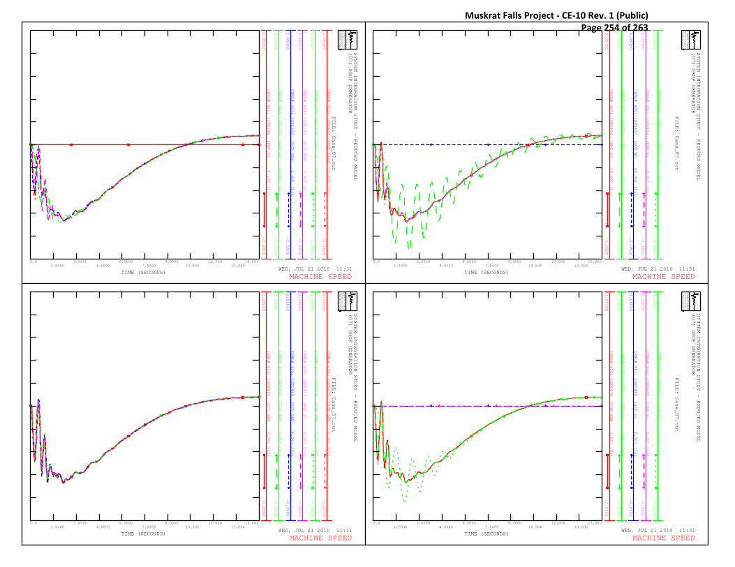
CHNL# 421: [SPD284 [PRV G1 4.20] [1]]
0.05000
-0.0500
CHNL# 422: [SPD290 [GCL G1 13.80] [1]]
0.05000
-0.0500
CHNL# 423: [SPD352 [SCV GEN 2.40] [1]]
0.05000
-0.0500
CHNL# 424: [SPD352 [SCV GEN 2.40] [2]]
0.05000
-0.0500
CHNL# 425: [SPD406 [USL G1 13.80] [1]]
0.05000
-0.0500
CHNL# 426: [SPD434 [HRP G1&G 16.00] [1]]
0.05000
-0.0500
SYSTEM INTEGRATION STUDY - REDUCED MODEL
(07) DROP GENERATOR
WED, JUL 21 2010 11:31TIME (SECONDS)
SIEMENS POWER
TECHNOLOGIES
INTERNATIONAL
R
0.01.5000
3.00004.5000
6.00007.5000
9.000010.500
12.00013.500
15.000
FILE: Case_07.out
MACHINE SPEED
CHNL# 427: [SPD436 [HRP G3 16.00] [1]]
0.05000
-0.0500
CHNL# 429: [SPD454 [TOP GEN 2.40] [1]]
0.05000
-0.0500
CHNL# 430: [SPD457 [GOU NP 66.00] [1]]
0.05000
-0.0500
CHNL# 431: [SPD464 [PBK G1 6.90] [1]]
0.05000
-0.0500
CHNL# 432: [SPD465 [MOB NP G 6.90] [1]]
0.05000
-0.0500
SYSTEM INTEGRATION STUDY - REDUCED MODEL
(07) DROP GENERATOR
WED, JUL 21 2010 11:31TIME (SECONDS)
SIEMENS POWER
TECHNOLOGIES
INTERNATIONAL
R
0.01.5000
3.00004.5000
6.00007.5000
9.000010.500
12.00013.500
15.000
FILE: Case_07.out
MACHINE SPEED
CHNL# 433: [SPD468 [TCV GEN 6.90] [1]]
0.05000
-0.0500
CHNL# 434: [SPD468 [TCV GEN 6.90] [2]]
0.05000
-0.0500
CHNL# 435: [SPD468 [TCV GEN 6.90] [3]]
0.05000
-0.0500
CHNL# 436: [SPD473 [ROP G1 6.90] [1]]
0.05000
-0.0500
CHNL# 437: [SPD478 [PHR GEN 2.30] [1]]
0.05000
-0.0500
CHNL# 438: [SPD478 [PHR GEN 2.30] [2]]
0.05000
-0.0500
SYSTEM INTEGRATION STUDY - REDUCED MODEL
(07) DROP GENERATOR
WED, JUL 21 2010 11:31TIME (SECONDS)
SIEMENS POWER
TECHNOLOGIES
INTERNATIONAL
R
0.01.5000
3.00004.5000
6.00007.5000
9.000010.500
12.00013.500
15.000
FILE: Case_07.out
MACHINE SPEED
CHNL# 439: [SPD478 [PHR GEN 2.30] [3]]
0.05000
-0.0500
CHNL# 440: [SPD483 [MRP G1 2.40] [1]]
0.05000
-0.0500
CHNL# 441: [SPD486 [HCP G1 6.90] [1]]
0.05000
-0.0500
CHNL# 442: [SPD488 [CAB G1 6.90] [1]]
0.05000
-0.0500
CHNL# 443: [SPD871 [SLK G1 13.80] [1]]
0.05000
-0.0500
SYSTEM INTEGRATION STUDY - REDUCED MODEL
(07) DROP GENERATOR
WED, JUL 21 2010 11:31TIME (SECONDS)
SIEMENS POWER
TECHNOLOGIES
INTERNATIONAL
R
0.01.5000
3.00004.5000
6.00007.5000
9.000010.500
12.00013.500
15.000
FILE: Case_07.out
MACHINE SPEED
Muskrat Falls Project - CE-10 Rev. 1 (Public) Page 254 of 263
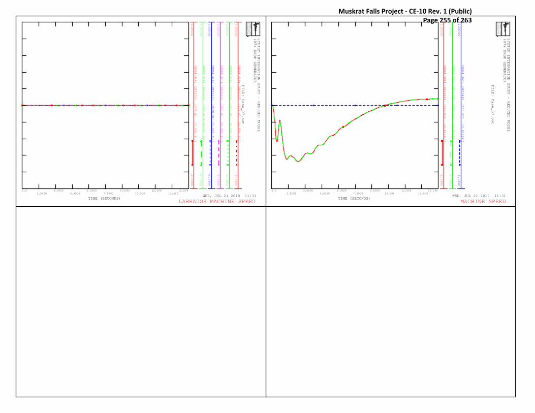
CHNL# 444: [SPD2101 [CHF A1 15.00] [1]]
0.05000
-0.0500
CHNL# 445: [SPD2102 [CHF A2-A 15.00] [2]]
0.05000
-0.0500
CHNL# 446: [SPD2115 [MUSK G1- 15.00] [1]]
0.05000
-0.0500
CHNL# 447: [SPD2121 [GUL G1 15.00] [1]]
0.05000
-0.0500
CHNL# 448: [SPD2122 [GUL G2 15.00] [2]]
0.05000
-0.0500
CHNL# 449: [SPD2137 [HVY G1 13.80] [1]]
0.05000
-0.0500
SYSTEM INTEGRATION STUDY - REDUCED MODEL
(07) DROP GENERATOR
WED, JUL 21 2010 11:31TIME (SECONDS)
SIEMENS POWER
TECHNOLOGIES
INTERNATIONAL
R
0.01.5000
3.00004.5000
6.00007.5000
9.000010.500
12.00013.500
15.000
FILE: Case_07.out
LABRADOR MACHINE SPEED
CHNL# 458: [SPD2494 [SOL SC1 13.80][1]]
0.05000
-0.0500
CHNL# 459: [SPD2495 [SOL SC2 13.80][2]]
0.05000
-0.0500
CHNL# 460: [SPD2496 [SOL SC3 13.80][3]]
0.05000
-0.0500
SYSTEM INTEGRATION STUDY - REDUCED MODEL
(07) DROP GENERATOR
WED, JUL 21 2010 11:31TIME (SECONDS)
SIEMENS POWER
TECHNOLOGIES
INTERNATIONAL
R
0.01.5000
3.00004.5000
6.00007.5000
9.000010.500
12.00013.500
15.000
FILE: Case_07.out
MACHINE SPEED
Muskrat Falls Project - CE-10 Rev. 1 (Public) Page 255 of 263

CHNL# 628: 60.0*(1+[FREQ153 [DPD L64 66]])
62.000
58.000
CHNL# 629: 60.0*(1+[FREQ204 [SVL B2 66]])
62.000
58.000
CHNL# 630: 60.0*(1+[FREQ308 [BLK NPT3 66]])
62.000
58.000
CHNL# 631: 60.0*(1+[FREQ309 [BRB T2T3 66]])
62.000
58.000
CHNL# 632: 60.0*(1+[FREQ319 [DLK NP 66]])
62.000
58.000
CHNL# 633: 60.0*(1+[FREQ334 [OPD B2B5 66]])
62.000
58.000
SYSTEM INTEGRATION STUDY - REDUCED MODEL
(07) DROP GENERATOR
WED, JUL 21 2010 11:31TIME (SECONDS)
SIEMENS POWER
TECHNOLOGIES
INTERNATIONAL
R
0.01.5000
3.00004.5000
6.00007.5000
9.000010.500
12.00013.500
15.000
FILE: Case_07.out
BUS FREQUENCY
CHNL# 634: 60.0*(1+[FREQ335 [HWD B7B8 66]])
62.000
58.000
CHNL# 635: 60.0*(1+[FREQ336 [WAV B2 66]])
62.000
58.000
CHNL# 636: 60.0*(1+[FREQ337 [HRD B6B7 66]])
62.000
58.000
CHNL# 637: 60.0*(1+[FREQ345 [ULT TAP 66]])
62.000
58.000
CHNL# 638: 60.0*(1+[FREQ346 [ULT NP 66]])
62.000
58.000
CHNL# 639: 60.0*(1+[FREQ347 [SCV NP 66]])
62.000
58.000
SYSTEM INTEGRATION STUDY - REDUCED MODEL
(07) DROP GENERATOR
WED, JUL 21 2010 11:31TIME (SECONDS)
SIEMENS POWER
TECHNOLOGIES
INTERNATIONAL
R
0.01.5000
3.00004.5000
6.00007.5000
9.000010.500
12.00013.500
15.000
FILE: Case_07.out
BUS FREQUENCY
CHNL# 640: 60.0*(1+[FREQ348 [KEL NP 66]])
62.000
58.000
CHNL# 641: 60.0*(1+[FREQ349 [CHA NP 66]])
62.000
58.000
CHNL# 642: 60.0*(1+[FREQ455 [GDL NP 66]])
62.000
58.000
CHNL# 643: 60.0*(1+[FREQ457 [GOU NP 66]])
62.000
58.000
CHNL# 646: 60.0*(1+[FREQ467 [TCV NP 66]])
62.000
58.000
CHNL# 652: 60.0*(1+[FREQ482 [MRP NP 66]])
62.000
58.000
SYSTEM INTEGRATION STUDY - REDUCED MODEL
(07) DROP GENERATOR
WED, JUL 21 2010 11:31TIME (SECONDS)
SIEMENS POWER
TECHNOLOGIES
INTERNATIONAL
R
0.01.5000
3.00004.5000
6.00007.5000
9.000010.500
12.00013.500
15.000
FILE: Case_07.out
BUS FREQUENCY
CHNL# 658: 60.0*(1+[FREQ550 [MOB NP 66]])
62.000
58.000
CHNL# 659: 60.0*(1+[FREQ558 [ROP NP 66]])
62.000
58.000
CHNL# 664: 60.0*(1+[FREQ973 [GOU MID1 66]])
62.000
58.000
CHNL# 665: 60.0*(1+[FREQ982 [CHA MID1 66]])
62.000
58.000
CHNL# 666: 60.0*(1+[FREQ111 [DLK B1 138]])
62.000
58.000
CHNL# 667: 60.0*(1+[FREQ112 [IRV B1 138]])
62.000
58.000
SYSTEM INTEGRATION STUDY - REDUCED MODEL
(07) DROP GENERATOR
WED, JUL 21 2010 11:31TIME (SECONDS)
SIEMENS POWER
TECHNOLOGIES
INTERNATIONAL
R
0.01.5000
3.00004.5000
6.00007.5000
9.000010.500
12.00013.500
15.000
FILE: Case_07.out
BUS FREQUENCY
Muskrat Falls Project - CE-10 Rev. 1 (Public) Page 256 of 263

CHNL# 668: 60.0*(1+[FREQ113 [SPL B1 138]])
62.000
58.000
CHNL# 669: 60.0*(1+[FREQ203 [BBK B2 138]])
62.000
58.000
CHNL# 670: 60.0*(1+[FREQ212 [HLY B1 138]])
62.000
58.000
CHNL# 671: 60.0*(1+[FREQ213 [HLK L43 138]])
62.000
58.000
CHNL# 672: 60.0*(1+[FREQ217 [STB B3 138]])
62.000
58.000
CHNL# 673: 60.0*(1+[FREQ219 [SOK L22 138]])
62.000
58.000
SYSTEM INTEGRATION STUDY - REDUCED MODEL
(07) DROP GENERATOR
WED, JUL 21 2010 11:31TIME (SECONDS)
SIEMENS POWER
TECHNOLOGIES
INTERNATIONAL
R
0.01.5000
3.00004.5000
6.00007.5000
9.000010.500
12.00013.500
15.000
FILE: Case_07.out
BUS FREQUENCY
CHNL# 674: 60.0*(1+[FREQ223 [SSD B2B3 138]])
62.000
58.000
CHNL# 675: 60.0*(1+[FREQ224 [BLA L12 138]])
62.000
58.000
CHNL# 676: 60.0*(1+[FREQ225 [LLK NP 138]])
62.000
58.000
CHNL# 677: 60.0*(1+[FREQ232 [MKS L12 138]])
62.000
58.000
CHNL# 678: 60.0*(1+[FREQ310 [BLK NP 138]])
62.000
58.000
CHNL# 679: 60.0*(1+[FREQ311 [WAV B4 138]])
62.000
58.000
SYSTEM INTEGRATION STUDY - REDUCED MODEL
(07) DROP GENERATOR
WED, JUL 21 2010 11:31TIME (SECONDS)
SIEMENS POWER
TECHNOLOGIES
INTERNATIONAL
R
0.01.5000
3.00004.5000
6.00007.5000
9.000010.500
12.00013.500
15.000
FILE: Case_07.out
BUS FREQUENCY
CHNL# 680: 60.0*(1+[FREQ338 [HRD B8 138]])
62.000
58.000
CHNL# 681: 60.0*(1+[FREQ340 [HOL NP 138]])
62.000
58.000
CHNL# 682: 60.0*(1+[FREQ353 [SPF NP 138]])
62.000
58.000
CHNL# 683: 60.0*(1+[FREQ354 [COL NP 138]])
62.000
58.000
CHNL# 684: 60.0*(1+[FREQ357 [BRB NP 138]])
62.000
58.000
CHNL# 685: 60.0*(1+[FREQ359 [MSY NP 138]])
62.000
58.000
SYSTEM INTEGRATION STUDY - REDUCED MODEL
(07) DROP GENERATOR
WED, JUL 21 2010 11:31TIME (SECONDS)
SIEMENS POWER
TECHNOLOGIES
INTERNATIONAL
R
0.01.5000
3.00004.5000
6.00007.5000
9.000010.500
12.00013.500
15.000
FILE: Case_07.out
BUS FREQUENCY
CHNL# 686: 60.0*(1+[FREQ371 [SPO NP 138]])
62.000
58.000
CHNL# 687: 60.0*(1+[FREQ603 [BBK B3 138]])
62.000
58.000
CHNL# 692: 60.0*(1+[FREQ205 [BBK B1 230]])
62.000
58.000
CHNL# 693: 60.0*(1+[FREQ206 [SVL B1 230]])
62.000
58.000
CHNL# 694: 60.0*(1+[FREQ208 [MDR B1B5 230]])
62.000
58.000
SYSTEM INTEGRATION STUDY - REDUCED MODEL
(07) DROP GENERATOR
WED, JUL 21 2010 11:31TIME (SECONDS)
SIEMENS POWER
TECHNOLOGIES
INTERNATIONAL
R
0.01.5000
3.00004.5000
6.00007.5000
9.000010.500
12.00013.500
15.000
FILE: Case_07.out
BUS FREQUENCY
Muskrat Falls Project - CE-10 Rev. 1 (Public) Page 257 of 263

CHNL# 696: 60.0*(1+[FREQ215 [BUC B1 230]])
62.000
58.000
CHNL# 697: 60.0*(1+[FREQ216 [STB B1B2 230]])
62.000
58.000
CHNL# 701: 60.0*(1+[FREQ227 [CBC B1B2 230]])
62.000
58.000
CHNL# 702: 60.0*(1+[FREQ229 [WAV B1B3 230]])
62.000
58.000
CHNL# 703: 60.0*(1+[FREQ230 [LHR B1 230]])
62.000
58.000
CHNL# 704: 60.0*(1+[FREQ234 [HRD TS 230]])
62.000
58.000
SYSTEM INTEGRATION STUDY - REDUCED MODEL
(07) DROP GENERATOR
WED, JUL 21 2010 11:31TIME (SECONDS)
SIEMENS POWER
TECHNOLOGIES
INTERNATIONAL
R
0.01.5000
3.00004.5000
6.00007.5000
9.000010.500
12.00013.500
15.000
FILE: Case_07.out
BUS FREQUENCY
CHNL# 705: 60.0*(1+[FREQ236 [HWD B1B2 230]])
62.000
58.000
CHNL# 706: 60.0*(1+[FREQ238 [OPD B1 230]])
62.000
58.000
CHNL# 708: 60.0*(1+[FREQ261 [ACG GFL 230]])
62.000
58.000
CHNL# 709: 60.0*(1+[FREQ291 [GCL L63 230]])
62.000
58.000
CHNL# 710: 60.0*(1+[FREQ405 [USL L34 230]])
62.000
58.000
CHNL# 711: 60.0*(1+[FREQ912 [TL202X 230]])
62.000
58.000
SYSTEM INTEGRATION STUDY - REDUCED MODEL
(07) DROP GENERATOR
WED, JUL 21 2010 11:31TIME (SECONDS)
SIEMENS POWER
TECHNOLOGIES
INTERNATIONAL
R
0.01.5000
3.00004.5000
6.00007.5000
9.000010.500
12.00013.500
15.000
FILE: Case_07.out
BUS FREQUENCY
CHNL# 712: 60.0*(1+[FREQ916 [TL206X 230]])
62.000
58.000
CHNL# 713: 60.0*(1+[FREQ918 [TLNEWX 230]])
62.000
58.000
CHNL# 714: 60.0*(1+[FREQ2181 [TL202Y 230]])
62.000
58.000
CHNL# 715: 60.0*(1+[FREQ2182 [TL206Y 230]])
62.000
58.000
CHNL# 716: 60.0*(1+[FREQ2183 [TLNEWY 230]])
62.000
58.000
CHNL# 726: 60.0*(1+[FREQ2490 [SOL B1 230]])
62.000
58.000
SYSTEM INTEGRATION STUDY - REDUCED MODEL
(07) DROP GENERATOR
WED, JUL 21 2010 11:31TIME (SECONDS)
SIEMENS POWER
TECHNOLOGIES
INTERNATIONAL
R
0.01.5000
3.00004.5000
6.00007.5000
9.000010.500
12.00013.500
15.000
FILE: Case_07.out
BUS FREQUENCY
CHNL# 717: 60.0*(1+[FREQ2301 [CHF A1 B 230]])
62.000
58.000
CHNL# 718: 60.0*(1+[FREQ2302 [CHF A2 & 230]])
62.000
58.000
CHNL# 719: 60.0*(1+[FREQ2307 [WABUSH T 230]])
62.000
58.000
CHNL# 720: 60.0*(1+[FREQ2308 [GUL 230 230]])
62.000
58.000
CHNL# 724: 60.0*(1+[FREQ2341 [GUL T1 230]])
62.000
58.000
CHNL# 725: 60.0*(1+[FREQ2342 [GUL T2 230]])
62.000
58.000
SYSTEM INTEGRATION STUDY - REDUCED MODEL
(07) DROP GENERATOR
WED, JUL 21 2010 11:31TIME (SECONDS)
SIEMENS POWER
TECHNOLOGIES
INTERNATIONAL
R
0.01.5000
3.00004.5000
6.00007.5000
9.000010.500
12.00013.500
15.000
FILE: Case_07.out
LABRADOR BUS FREQUENCY
Muskrat Falls Project - CE-10 Rev. 1 (Public) Page 258 of 263

CHNL# 470: [VOLT115 [MDR B2B3 66]]
1.2000
0.0
CHNL# 471: [VOLT151 [BUC B2 66]]
1.2000
0.0
CHNL# 472: [VOLT152 [MDR B4 66]]
1.2000
0.0
CHNL# 473: [VOLT153 [DPD L64 66]]
1.2000
0.0
CHNL# 474: [VOLT204 [SVL B2 66]]
1.2000
0.0
CHNL# 475: [VOLT308 [BLK NPT3 66]]
1.2000
0.0
SYSTEM INTEGRATION STUDY - REDUCED MODEL
(07) DROP GENERATOR
WED, JUL 21 2010 11:31TIME (SECONDS)
SIEMENS POWER
TECHNOLOGIES
INTERNATIONAL
R
0.01.5000
3.00004.5000
6.00007.5000
9.000010.500
12.00013.500
15.000
FILE: Case_07.out
VOLTAGE
CHNL# 476: [VOLT309 [BRB T2T3 66]]
1.2000
0.0
CHNL# 477: [VOLT319 [DLK NP 66]]
1.2000
0.0
CHNL# 478: [VOLT334 [OPD B2B5 66]]
1.2000
0.0
CHNL# 479: [VOLT335 [HWD B7B8 66]]
1.2000
0.0
CHNL# 480: [VOLT336 [WAV B2 66]]
1.2000
0.0
CHNL# 481: [VOLT337 [HRD B6B7 66]]
1.2000
0.0
SYSTEM INTEGRATION STUDY - REDUCED MODEL
(07) DROP GENERATOR
WED, JUL 21 2010 11:31TIME (SECONDS)
SIEMENS POWER
TECHNOLOGIES
INTERNATIONAL
R
0.01.5000
3.00004.5000
6.00007.5000
9.000010.500
12.00013.500
15.000
FILE: Case_07.out
VOLTAGE
CHNL# 482: [VOLT345 [ULT TAP 66]]
1.2000
0.0
CHNL# 483: [VOLT346 [ULT NP 66]]
1.2000
0.0
CHNL# 484: [VOLT347 [SCV NP 66]]
1.2000
0.0
CHNL# 485: [VOLT348 [KEL NP 66]]
1.2000
0.0
CHNL# 486: [VOLT349 [CHA NP 66]]
1.2000
0.0
CHNL# 487: [VOLT455 [GDL NP 66]]
1.2000
0.0
SYSTEM INTEGRATION STUDY - REDUCED MODEL
(07) DROP GENERATOR
WED, JUL 21 2010 11:31TIME (SECONDS)
SIEMENS POWER
TECHNOLOGIES
INTERNATIONAL
R
0.01.5000
3.00004.5000
6.00007.5000
9.000010.500
12.00013.500
15.000
FILE: Case_07.out
VOLTAGE
CHNL# 488: [VOLT457 [GOU NP 66]]
1.2000
0.0
CHNL# 489: [VOLT463 [KEN NP 66]]
1.2000
0.0
CHNL# 490: [VOLT466 [KBR NP 66]]
1.2000
0.0
CHNL# 491: [VOLT467 [TCV NP 66]]
1.2000
0.0
CHNL# 492: [VOLT469 [MUN NP 66]]
1.2000
0.0
CHNL# 493: [VOLT471 [MOL NP 66]]
1.2000
0.0
SYSTEM INTEGRATION STUDY - REDUCED MODEL
(07) DROP GENERATOR
WED, JUL 21 2010 11:31TIME (SECONDS)
SIEMENS POWER
TECHNOLOGIES
INTERNATIONAL
R
0.01.5000
3.00004.5000
6.00007.5000
9.000010.500
12.00013.500
15.000
FILE: Case_07.out
VOLTAGE
Muskrat Falls Project - CE-10 Rev. 1 (Public) Page 259 of 263

CHNL# 494: [VOLT474 [PEP NP 66]]
1.2000
0.0
CHNL# 495: [VOLT479 [PUL NP 66]]
1.2000
0.0
CHNL# 496: [VOLT481 [RRD NP 66]]
1.2000
0.0
CHNL# 497: [VOLT482 [MRP NP 66]]
1.2000
0.0
CHNL# 498: [VOLT484 [SJM NP 66]]
1.2000
0.0
CHNL# 499: [VOLT485 [HCP NP 66]]
1.2000
0.0
SYSTEM INTEGRATION STUDY - REDUCED MODEL
(07) DROP GENERATOR
WED, JUL 21 2010 11:31TIME (SECONDS)
SIEMENS POWER
TECHNOLOGIES
INTERNATIONAL
R
0.01.5000
3.00004.5000
6.00007.5000
9.000010.500
12.00013.500
15.000
FILE: Case_07.out
VOLTAGE
CHNL# 500: [VOLT489 [SLA NP 66]]
1.2000
0.0
CHNL# 501: [VOLT492 [VIR NP 66]]
1.2000
0.0
CHNL# 502: [VOLT510 [BIG NP 66]]
1.2000
0.0
CHNL# 503: [VOLT550 [MOB NP 66]]
1.2000
0.0
CHNL# 504: [VOLT558 [ROP NP 66]]
1.2000
0.0
CHNL# 505: [VOLT576 [CAB NP 66]]
1.2000
0.0
SYSTEM INTEGRATION STUDY - REDUCED MODEL
(07) DROP GENERATOR
WED, JUL 21 2010 11:31TIME (SECONDS)
SIEMENS POWER
TECHNOLOGIES
INTERNATIONAL
R
0.01.5000
3.00004.5000
6.00007.5000
9.000010.500
12.00013.500
15.000
FILE: Case_07.out
VOLTAGE
CHNL# 506: [VOLT579 [FER NP 66]]
1.2000
0.0
CHNL# 507: [VOLT870 [SLK L80 66]]
1.2000
0.0
CHNL# 508: [VOLT920 [MOB MID3 66]]
1.2000
0.0
CHNL# 509: [VOLT973 [GOU MID1 66]]
1.2000
0.0
CHNL# 510: [VOLT982 [CHA MID1 66]]
1.2000
0.0
CHNL# 511: [VOLT111 [DLK B1 138]]
1.2000
0.0
SYSTEM INTEGRATION STUDY - REDUCED MODEL
(07) DROP GENERATOR
WED, JUL 21 2010 11:31TIME (SECONDS)
SIEMENS POWER
TECHNOLOGIES
INTERNATIONAL
R
0.01.5000
3.00004.5000
6.00007.5000
9.000010.500
12.00013.500
15.000
FILE: Case_07.out
VOLTAGE
CHNL# 512: [VOLT112 [IRV B1 138]]
1.2000
0.0
CHNL# 513: [VOLT113 [SPL B1 138]]
1.2000
0.0
CHNL# 514: [VOLT203 [BBK B2 138]]
1.2000
0.0
CHNL# 515: [VOLT212 [HLY B1 138]]
1.2000
0.0
CHNL# 516: [VOLT213 [HLK L43 138]]
1.2000
0.0
CHNL# 517: [VOLT217 [STB B3 138]]
1.2000
0.0
SYSTEM INTEGRATION STUDY - REDUCED MODEL
(07) DROP GENERATOR
WED, JUL 21 2010 11:31TIME (SECONDS)
SIEMENS POWER
TECHNOLOGIES
INTERNATIONAL
R
0.01.5000
3.00004.5000
6.00007.5000
9.000010.500
12.00013.500
15.000
FILE: Case_07.out
VOLTAGE
Muskrat Falls Project - CE-10 Rev. 1 (Public) Page 260 of 263

CHNL# 518: [VOLT219 [SOK L22 138]]
1.2000
0.0
CHNL# 519: [VOLT223 [SSD B2B3 138]]
1.2000
0.0
CHNL# 520: [VOLT224 [BLA L12 138]]
1.2000
0.0
CHNL# 521: [VOLT225 [LLK NP 138]]
1.2000
0.0
CHNL# 522: [VOLT232 [MKS L12 138]]
1.2000
0.0
CHNL# 523: [VOLT310 [BLK NP 138]]
1.2000
0.0
SYSTEM INTEGRATION STUDY - REDUCED MODEL
(07) DROP GENERATOR
WED, JUL 21 2010 11:31TIME (SECONDS)
SIEMENS POWER
TECHNOLOGIES
INTERNATIONAL
R
0.01.5000
3.00004.5000
6.00007.5000
9.000010.500
12.00013.500
15.000
FILE: Case_07.out
VOLTAGE
CHNL# 524: [VOLT311 [WAV B4 138]]
1.2000
0.0
CHNL# 525: [VOLT338 [HRD B8 138]]
1.2000
0.0
CHNL# 526: [VOLT340 [HOL NP 138]]
1.2000
0.0
CHNL# 527: [VOLT353 [SPF NP 138]]
1.2000
0.0
CHNL# 528: [VOLT354 [COL NP 138]]
1.2000
0.0
CHNL# 529: [VOLT357 [BRB NP 138]]
1.2000
0.0
SYSTEM INTEGRATION STUDY - REDUCED MODEL
(07) DROP GENERATOR
WED, JUL 21 2010 11:31TIME (SECONDS)
SIEMENS POWER
TECHNOLOGIES
INTERNATIONAL
R
0.01.5000
3.00004.5000
6.00007.5000
9.000010.500
12.00013.500
15.000
FILE: Case_07.out
VOLTAGE
CHNL# 530: [VOLT359 [MSY NP 138]]
1.2000
0.0
CHNL# 531: [VOLT371 [SPO NP 138]]
1.2000
0.0
CHNL# 532: [VOLT603 [BBK B3 138]]
1.2000
0.0
SYSTEM INTEGRATION STUDY - REDUCED MODEL
(07) DROP GENERATOR
WED, JUL 21 2010 11:31TIME (SECONDS)
SIEMENS POWER
TECHNOLOGIES
INTERNATIONAL
R
0.01.5000
3.00004.5000
6.00007.5000
9.000010.500
12.00013.500
15.000
FILE: Case_07.out
VOLTAGE
CHNL# 536: [VOLT136 [CAT L47 230]]
1.2000
0.0
CHNL# 537: [VOLT205 [BBK B1 230]]
1.2000
0.0
CHNL# 538: [VOLT206 [SVL B1 230]]
1.2000
0.0
CHNL# 539: [VOLT208 [MDR B1B5 230]]
1.2000
0.0
CHNL# 540: [VOLT211 [NLREFINE 230]]
1.2000
0.0
SYSTEM INTEGRATION STUDY - REDUCED MODEL
(07) DROP GENERATOR
WED, JUL 21 2010 11:31TIME (SECONDS)
SIEMENS POWER
TECHNOLOGIES
INTERNATIONAL
R
0.01.5000
3.00004.5000
6.00007.5000
9.000010.500
12.00013.500
15.000
FILE: Case_07.out
VOLTAGE
Muskrat Falls Project - CE-10 Rev. 1 (Public) Page 261 of 263

CHNL# 543: [VOLT218 [PIPERS_H 230]]
1.2000
0.0
CHNL# 544: [VOLT221 [BDE TS 230]]
1.2000
0.0
CHNL# 545: [VOLT222 [SSD B1 230]]
1.2000
0.0
CHNL# 546: [VOLT227 [CBC B1B2 230]]
1.2000
0.0
CHNL# 547: [VOLT229 [WAV B1B3 230]]
1.2000
0.0
SYSTEM INTEGRATION STUDY - REDUCED MODEL
(07) DROP GENERATOR
WED, JUL 21 2010 11:31TIME (SECONDS)
SIEMENS POWER
TECHNOLOGIES
INTERNATIONAL
R
0.01.5000
3.00004.5000
6.00007.5000
9.000010.500
12.00013.500
15.000
FILE: Case_07.out
VOLTAGE
CHNL# 548: [VOLT230 [LHR B1 230]]
1.2000
0.0
CHNL# 549: [VOLT234 [HRD TS 230]]
1.2000
0.0
CHNL# 550: [VOLT236 [HWD B1B2 230]]
1.2000
0.0
CHNL# 551: [VOLT238 [OPD B1 230]]
1.2000
0.0
CHNL# 552: [VOLT260 [ACS SVL 230]]
1.2000
0.0
SYSTEM INTEGRATION STUDY - REDUCED MODEL
(07) DROP GENERATOR
WED, JUL 21 2010 11:31TIME (SECONDS)
SIEMENS POWER
TECHNOLOGIES
INTERNATIONAL
R
0.01.5000
3.00004.5000
6.00007.5000
9.000010.500
12.00013.500
15.000
FILE: Case_07.out
VOLTAGE
CHNL# 553: [VOLT261 [ACG GFL 230]]
1.2000
0.0
CHNL# 554: [VOLT291 [GCL L63 230]]
1.2000
0.0
CHNL# 555: [VOLT405 [USL L34 230]]
1.2000
0.0
CHNL# 556: [VOLT912 [TL202X 230]]
1.2000
0.0
CHNL# 557: [VOLT916 [TL206X 230]]
1.2000
0.0
SYSTEM INTEGRATION STUDY - REDUCED MODEL
(07) DROP GENERATOR
WED, JUL 21 2010 11:31TIME (SECONDS)
SIEMENS POWER
TECHNOLOGIES
INTERNATIONAL
R
0.01.5000
3.00004.5000
6.00007.5000
9.000010.500
12.00013.500
15.000
FILE: Case_07.out
VOLTAGE
CHNL# 558: [VOLT918 [TLNEWX 230]]
1.2000
0.0
CHNL# 559: [VOLT2181 [TL202Y 230]]
1.2000
0.0
CHNL# 560: [VOLT2182 [TL206Y 230]]
1.2000
0.0
CHNL# 561: [VOLT2183 [TLNEWY 230]]
1.2000
0.0
SYSTEM INTEGRATION STUDY - REDUCED MODEL
(07) DROP GENERATOR
WED, JUL 21 2010 11:31TIME (SECONDS)
SIEMENS POWER
TECHNOLOGIES
INTERNATIONAL
R
0.01.5000
3.00004.5000
6.00007.5000
9.000010.500
12.00013.500
15.000
FILE: Case_07.out
VOLTAGE
Muskrat Falls Project - CE-10 Rev. 1 (Public) Page 262 of 263

CHNL# 61: [ANGL2490 [SOL B1 230.00][1]]
500.00
-500.0
CHNL# 457: [SPD2490 [SOL B1 230.00][1]]
0.50000
-0.5000
SYSTEM INTEGRATION STUDY - REDUCED MODEL
(07) DROP GENERATOR
THU, MAR 04 2010 18:14TIME (SECONDS)
SIEMENS POWER
TECHNOLOGIES
INTERNATIONAL
R
0.01.5000
3.00004.5000
6.00007.5000
9.000010.500
12.00013.500
15.000
FILE: Case_07.out
MACHINE BUS 2490
CHNL# 127: 100*[POWR2490 [SOL B1 230.00][1]]
50.000
-50.00
CHNL# 193: 100*[VARS2490 [SOL B1 230.00][1]]
50.000
-50.00
SYSTEM INTEGRATION STUDY - REDUCED MODEL
(07) DROP GENERATOR
THU, MAR 04 2010 18:14TIME (SECONDS)
SIEMENS POWER
TECHNOLOGIES
INTERNATIONAL
R
0.01.5000
3.00004.5000
6.00007.5000
9.000010.500
12.00013.500
15.000
FILE: Case_07.out
MACHINE BUS 2490
CHNL# 773: 100*[SOLP_P1_MW]
100.00
-400.0
CHNL# 775: 100*[SOLP_P2_MW]
100.00
-400.0
SYSTEM INTEGRATION STUDY - REDUCED MODEL
(07) DROP GENERATOR
THU, MAR 04 2010 18:14TIME (SECONDS)
SIEMENS POWER
TECHNOLOGIES
INTERNATIONAL
R
0.01.5000
3.00004.5000
6.00007.5000
9.000010.500
12.00013.500
15.000
FILE: Case_07.out
HVDC, MW
CHNL# 774: 100*[SOLP_P2_MVAR]
400.00
-100.0
CHNL# 776: 100*[SOLP_P2_MVAR]
400.00
-100.0
SYSTEM INTEGRATION STUDY - REDUCED MODEL
(07) DROP GENERATOR
THU, MAR 04 2010 18:14TIME (SECONDS)
SIEMENS POWER
TECHNOLOGIES
INTERNATIONAL
R
0.01.5000
3.00004.5000
6.00007.5000
9.000010.500
12.00013.500
15.000
FILE: Case_07.out
HVDC, MVAR
Muskrat Falls Project - CE-10 Rev. 1 (Public) Page 263 of 263