Disembodied and Collaborative Musical Interaction in the ...

PianoTable
Musical Interaction on a tabletop display10th Semester Project - Spring 2007
Study group IMM1072BFrédéric Boulet
Intelligent Multimedia specializationAalborg University

Aalborg University
DEPARTMENT OF ELECTRONIC SYSTEMS
INTELLIGENT MULTIMEDIA 10TH SEMESTER
Title:PianoTable
Project Period:February 2007 toJune 2007
Project Group:1072B
Group Member:Frédéric Boulet
Supervisor:Zheng-Hua Tan
Number of Copies:3
Report Pages:61
Synopsis:
The main purpose of this study is to explore theinteraction between a musical application and atabletop display. This is achieved by exploring areas such as Human Computer Interaction (HCI), Computer Graphics and Image Processing.This project details the interaction paradigm of playing piano using the pressure of fingers on a rear-projected surface. This was achieved by developing a graphical piano keyboard, an audio synthesize, and a fingertip recognition software.Usability testing showed that the quality of the fingertip spotting is not accurate enough to perform piano-like music. Latency between a pressure and the music is also an issue.However, the interaction paradigm with the tabletop display please users, so that they would be interested by other application taking advantage of this system.Nevertheless, this study identified areas for improvements that could enhance the system.
3


Preface
This project has been conducted at the Intelligent Multimedia specialization at the Department of Electronic Systems of Aalborg University. It has been composed on the 10th semester in the Spring 2007, running from February to June 2007. This report is dedicated to the supervisor of the group, the examiners, and fellow students who might be interested in the issues presented in this project.
I would like to thank Zheng-Hua Tan for his assistance, support and advice on various key points along the semester.
Parts of this project are also used in the DemeTouch [1] project, which is a different declination of this interaction paradigm. These projects also share the part about light source positioning, camera testing and the image processing techniques. The separation of the two thesis projects has been made in agreement with the E-study board.
The intended audience is not expected to have any prior knowledge about Human Computer Interaction or Computer Assisted Music, but general software development and music knowledge can still be advisable.
Throughout the report, references to literature are presented with numberings e.g. Midi [2]; the bibliography is located at the end of the report.
Outline of the report:
The report is divided into five chapters: Introduction, Analysis, Design, Implementation, Usability evaluation and Conclusion.
Frédéric Boulet
5


Contents
Chapter 1: Introduction 111.1: Context.............................................................................................................. 13
1.1.1 General Introduction on tabletop display............................................ 131.1.2 Touch Screen.......................................................................................13
1.2: Project Definition & Focus................................................................................151.2.1 Definition............................................................................................ 151.2.2 Focus................................................................................................... 15
Chapter 2: Analysis 172.1: Tabletop display system.................................................................................... 19
2.1.1 Projection methods..............................................................................192.1.2 Usages................................................................................................. 202.1.3 Existing tabletop display system......................................................... 20
2.2: Human Computer Interfaces..............................................................................232.3: Video input........................................................................................................ 252.4: Audio output......................................................................................................29
2.4.1 PureData.............................................................................................. 292.4.2 Introduction to MIDI...........................................................................29
2.5: Basics of Piano.................................................................................................. 31
Chapter 3: Design 333.1: The Graphical User Interface............................................................................ 35
3.1.1 The Java Graphic API......................................................................... 353.1.2 The Graphical Piano............................................................................36
3.2: Sound Architecture............................................................................................393.2.1 The Midi package................................................................................39
3.3: Finger spotting and video processing................................................................ 413.3.1 The Java Media Framework................................................................413.3.2 Design of the Video Processing component....................................... 413.3.3 Image processing.................................................................................423.3.4 API...................................................................................................... 463.3.5 Video processing GUI.........................................................................47
3.4: The PianoTable..................................................................................................493.4.1 Calibration of each Piano key............................................................. 493.4.2 Main software loop..............................................................................503.4.3 Stability issues.....................................................................................50
3.5: Implementation..................................................................................................51
Chapter 4: Usability evaluation and Conclusion 534.1: User Feedback................................................................................................... 55
4.1.1 Playing a music tune........................................................................... 55
7


4.1.2 Playing intervals and triads................................................................. 554.1.3 Calibration procedure..........................................................................564.1.4 Users comments.................................................................................. 56
4.2: Conclusion.........................................................................................................57
Bibliography 59
Figures Index 61
9


CHAPTER 1: INTRODUCTION
There is nowadays a trend towards innovative user interfaces. The fiction movie Minority Report showcased off a computer interface where the user can use fingers to interact with his desktop and manage work tasks.
The website YouTube features a lot of popular computer science videos among the “most viewed videos”, most of them being screen capture of innovative and visually impressive user interfaces.
This trend shows that new approaches to user interaction can be well received a good welcome from the public.
There has always been a lot of experimentation around tangible user interfaces, beyond the invention or the mouse and the Graphical User Interface by the Xerox PARC lab.
The touchscreen interface is widespread, and is built into a lot of consumer devices. However, most of these devices only have one sensitive point of contact. Multiple simultaneous contacts result in an unpredictable behavior.
Multitouch interfaces appeared in the 80's but few of them got out of laboratories. A recent attempt from a research team in New York demonstrated a lot of applications that could benefit from multitouch interfaces [3]. Even if the principle is not new, these “proofs of concept” show how this kind of interface could change the way people interact with computers.
11

1.1: Context
This chapter will discuss the various elements which lead to the definition of the project.
1.1.1 General Introduction on tabletop display
A tabletop display can be quickly described as interactive table which embeds a screen and one or several input modalities (voice, computer vision, but also mouse or keyboard), used to perform desktop tasks in a more interactive manner (augmented workbenches...), or any task that can benefit from this setup compared to a standard desktop computer such as collaborative work.
Reactable
Considering music, the Reactable[4] demonstrated an impressive solution to interact with a user to play music. This system uses fingers and fiducial, i.e. distinguishable objects to play music. The authors state that it is a new breed of instrument, and that it is easy to learn.
It has recently been used by a mainstream artist, the Icelandic Bjork who used the Reactable as a key component of her worldwide tour[5].
1.1.2 Touch Screen
Invented in 1971, touchscreens are now very popular. Their field of use is broad , and they appeared on a wide product range such as cash machine or PDAs, sometimes in combination with a stylus.
The growing popularity of mobile devices drives the acceptance of this kind of technology, since it creates a good user experience.
13
Fig. 1.1.1: Artist Björk uses Reactable at Coachella festival

Chapter 1: Introduction
Touchscreens are popular in industry and in other situations, such as museum displays or room automation, where keyboards and mice do not allow a satisfactory, intuitive, rapid, or accurate interaction by the user with the displays' content.
At the beginning, these devices were not widely spread, but a consumer trend pushes integrators and manufacturers since it is a highly desirable interface component. It is now often considered as a fundamental part of a product's design.
A lot of research nowadays has been conducted on Frustrated Total Internal Reflection, which consists in emitting infrared light from the side of a glass surface. When the surface is pressed, the light gets out the glass and can then be detected by IR sensitive hardware.
This system provides excellent multitouch capabilities and is considered as the state-of-art of multitouch interface, along with its specifically designed applications.
14
Fig. 1.1.2: FTIR glass side view [3]

1.2: Project Definition & Focus
1.2.1 Definition
This project consists in leveraging a tabletop display by developing a virtual piano. The user will use his fingertips to interact with the system, and play piano.
1.2.2 Focus
As described later, the system uses a camera, hence there will be a special care towards the fingertips detection engine.
Real pianos allow several keys to be pressed at the same time to play chords, hence the prototype will be sensible to multiple points of contact.
The software architecture will be extensible so that the prototype might be later improved into a kind of “piano learning application”, by adding visual components.
The emphasis will be put on simplicity of use. It will also be the occasion to test if such an application is fitted to play a classical instrument on such a setup.
15


CHAPTER 2: ANALYSIS
This chapter will describe the basis upon which this project is built, and the modifications applied on an existing system to leverage its input modality, by adding components to enable fingertip interaction.
17


2.1: Tabletop display system
Tabletop display systems are a special type of systems, containing hardware and software as well as some form of table, that are designed to render computer images on a rear-projected surface. Different tabletop display systems differ primarily in their usage and projection methods that are about to be discussed. An existing tabletop display system, present at Aalborg University, will also be described, as it will be the key point of this project.
2.1.1 Projection methods
The display of images on the table drawing surface can be done by projecting the image from above or below, or by embedding some type of computer screen in the table surface itself. Figures below illustrate how a tabletop display system with top or bottom projection can be implemented.
Top Projection enables user positioning all around the table, and potentially making room for additional users. However, as the image is projected from above, users may occlude parts of the image by casting shadows from hands, heads or torsos. This may be particularly annoying when a user uses an input device such as a stylus or his finger on the table, with his hand occluding the part of the screen he wishes to interact with (Fig. 3.1.1, right schematic).
With bottom projection, users cannot occlude the projection or parts of the image. The projector must in most cases be placed to the side of the screen (Fig. 3.1.1, left schematic), potentially limiting the availability of the screen from on side and thus decreasing the number of users.
19
Fig. 2.1.1: Tabletop, side view, bottom and top projection

Chapter 2: Analysis
An embedded screen solves both problems since users do not occlude any projection light, and the screen may be accessible from all angles. However, such screens are not cheap, and may be more fragile if no precaution is taken. Furthermore, one of the starting point of the project being the Reactable, it is intended to expand it with the possibility of using tangibles. Detecting and tracking objects laying on the screen surface is a feature that no such screen offers today.
2.1.2 Usages
The tabletop concept is likely to be used for several kind of applications, corresponding to slightly different setups [6].
Digital desks:
Single user, sort of advanced desktop. Incorporates much of the features expected from a regular desk in a given environment.
Workbenches:
Combines a tabletop display with headmounted devices to create a virtual environment that users may interact with. Used where a virtual manipulation of an object is preferable.
Drafting tables:
Single user, advanced drafter table, built to fit their needs. More creative job function.
Collaboration tables:
To be used by a group in cooperation. These tables provide input methods for several users, and are used for designing, planning and other group related tasks.
The content of this project seems to be more a mix of several of these setups.
2.1.3 Existing tabletop display system
The in-house tabletop display system, which will be used in this project, was originally designed and constructed at Aalborg university by Soren Larsen in 2005 [7], and subsequently used in [8]. The tabletop display system was redesigned during summer 2006. It uses rear-projection from the bottom (fig up) and consists of a computer, a wide angle XGA projector(Hitachi CP-X275), a mirror, a wooden tabletop and a wooden frame. A screen image from the computer is projected and then reflected by the mirror onto the bottom of the glass plate, where it illuminates a specifically crafted rear-projection material covering the plate. The image is now visible from above the table.
20

2.1:Tabletop display system
The tabletop display system is accessible from three out of four sides; the back side of the table, housing the projector, may be used as a regular table, but then the display is somehow unavailable for interactive purposes.
The table could be shorter but there is a requirement of the projector to be placed at a minimum distance from the surface.
21
Fig. 2.1.3: Tabletop, front view
Fig. 2.1.2: Tabletop, Dimensions


2.2: Human Computer Interfaces
Human Computer Interaction is described to investigate the objectives this study must achieve in order to provide a good user experience.
Today many interactive products exist and many of them require a user interface (UI) that makes comfortable and intuitive for the user to interact with them. Unfortunately, not all products have a good UI and the reason for this may be, among other things, that the developers put more efforts in the system engineering than on the usability. Most of the time, developers rely on "common sense" to build the UI, even if it is a paradoxically relative notion. ISO 9241 part 11 defines usability in the following way:
“The extent to which a product can be used by specified users to achieve specified goals with effectiveness, efficiency and satisfaction in a specified context of use.” [9]
Usability is a way of measuring how good the user experience is, regarding the three mentioned points.
The UI design has to focus on the primary objectives of the system. It can be efficiency, but the UI can also focus on an effective learning on how to use the system. These objectives are called "usability goals and user experience goals" [10].
The usability goals are concerned with meeting specific usability criteria, such as efficiency, effectiveness, safety (diminishing the risk of an undesired manipulation) and learnability.
The UI of this project will focus more on effectiveness, since the task of playing piano is simple and does not require any learning process.
The user experience goals are more about how using the application feels like, for example how a gaming application is actually fun to use.
Concerning these objectives, this study aims to make the user experience esthetically pleasing and enjoyable, by being intuitive and entertaining.
A user test will be performed to see if these objectives are reached.
23


2.3: Video input
The Computer Vision component of the Reactable is called ReactiVision. It is publicly available under the free GPL license. Efficient and robust, it is used to detect the fiducials on the tabletop surface. However, the public version of this engine does not detect and tracks fingertips, though that feature is available in the Reactable setup.
For that reason, this project also focuses on the design of a specific vision engine.
In [11], the input devices are defined as the physical tools used to implement various interaction techniques. It is important to consider what techniques to use in order to achieve natural, efficient and appropriate user interaction.
Previous projects used ultrasonic pens as the input device to interact with the software on the previously mentioned tabletop [12].
This project tries to adopt a more natural approach to that fundamental point, by letting the user interact with his fingertips.
It appears that the table's material has an unexpected optic property. From beneath, it is impossible to see through. However, it appears that the material is almost transparent for an object lying less than 1 cm or so of the surface. Hence, the cover of a book is readable, symbols are also distinctly visible with a satisfying contrast. Most of all, the direct contact of a finger is also clearly distinguishable (Fig. 2.3.1 and Fig. 3.3.1).
From that observation, a camera is placed under the projector, at a position and a distance that balance
25
Fig. 2.3.1: View from under the table

Chapter 2: Analysis
both field of view and image quality, a good placement being a requirement. Placing the camera right under the projector yields acceptable results.
One of the issues is that the operating projector will generate an unwanted noise, since the camera will also receive the reflection of the projected image, which leads to a less accurate finger spotting process. Fortunately, the projector emits light only in the visible spectrum, while the camera CMOS sensor is sensible to IR (InfraRed) light once the IR filter (a thin tinted layer between the sensor and the camera objective) of the camera is removed. To achieve this separation, a visible light blocker (two layers of photographic film) is added to the camera.
However, it appears that the ambient IR illumination is not sufficient to provide enough contrast for any kind of computer processing. It is necessary to use an artificial source of IR light. Different solutions
26
Fig. 2.3.2: Tabletop setup. View from under the table
Fig. 2.3.3: Tabletop setup, visible red light glow
2.3:Video input
were considered; one of them involved the use of hundreds of low power IR emitting diodes. The solution that was chosen is the use of on-the-shelf IR lamps.
Hence, two high power IR light bulbs were added to the setup, one at each side of the table. Unfortunately, they also strongly emit in the visible red spectrum (Fig. 2.3.3), but this illumination can be filtered out using a green tinted layer of transparent plastic. IR light goes through most of these layers.
The detection of fingertips on the camera image operates in the camera coordinates system, whereas the computer graphic card operates in its own coordinate system. It is then difficult to find a simple relation between the two coordinates systems due to the tabletop parameters such as distance from projector to surface, mirror and camera placement. It is therefore important to calibrate the system before the first use.
Different techniques can be considered for calibration, which will be detailed and discussed in the design part since the calibration strategy can differ for different applications.
The quality of the image and the transfer latency depends on the hardware and its interface. IEEE1394 (FireWire) is usually faster than USB 2 and is then capable of reaching a lower latency.
The quality of the CMOS sensor in the IR spectrum is also fundamental. Two cameras have been tested with this setup:
• Phillips ToUcam Pro II (USB 2)
• Unibrain Fire-i (IEEE1394)
The latter gives a sharper image, and is better because it also features a better lens. It is also a bit more expensive, and is sometimes not compatible with the Java Media Framework which is the standard way of acquiring video in Java.
As a whole, the Reactable project proved that this solution was a satisfying solution for tabletop interaction, and many ideas for this setup are inspired from the ReactiVision project.
27


2.4: Audio output
Computer generated music is a topic that has been extensively researched. A lot of popular programs are available freely to build artificial sounds, hence without using “real” audio samples.
2.4.1 PureData
The Reactable uses the PureData software to generate sounds. PureData uses “patches” [13], i.e. a set of components to generate, transform, filter, add or remove noise from audio samples or synthetic sounds. Patches can be very complicated, but even a patch with a limited number of components can yield interesting audio results. PureData provides an API (Application Programming Interface) to allow others applications to communicate with it.
However, the PianoTable only aims to play a single instrument, hence this project will use MIDI as the sound interface.
2.4.2 Introduction to MIDI
Midi (Musical Instrument Interface) [2] is a norm created in the 1982 to provide musicians and sound professionals with a unified standard to have their devices communicating with each others. It is a protocol of command and control allowing the share of information between electronic musical instruments, while one or several of these being computers. It even allows devices to be dedicated to the control of other devices. For example, a master MIDI table could control dozens of different parameters on different devices.
On hardware devices, a MIDI communication port is a 5-pin DIN input. However, most Operating Systems can execute software emulating MIDI, hence removing the need for a hardware device, and allowing a software replacement such as a software synthesizer, or a graphical control front end. Of course, both approaches are compatible, it is then possible to use both the software MIDI of the computer while communicating through the MIDI port, provided it has a MIDI card.
Since Windows 3.0, the Microsoft OS offers MIDI facilities without installing any other software. It even includes a software synthesizer based on wave tables to provide a quick access to sound generation and an API to use it with other softwares.
29


2.5: Basics of Piano
The piano is a percussion instrument. The mechanism of a piano is actually a series of hammers that hit strings. Each individual note has one or several strings that are tuned to that tone. It has actually hundreds of strings producing its tones.
There is typically two or three peddles at the bottom of a piano.
The right peddle always has the same function. It is called the dampener and when pressed the note is sustained until let. The middle and left peddles function differently depending on the piano.
Typically, pianos have around 88 keys, this number can rise to more than a hundred on Grand Pianos.
An interval describes the space between two notes, and a chord refers to three or more notes with a skip between each one. Those that have three notes are called triads. If another note is added it is then a seventh chord because the interval from the base up to the top note is seven. All the other chords that are referred to by a number are reflecting the intervals from the bottom to the top.
31

CHAPTER 3: DESIGN
The main focus of the application is to provide a similar piano experience to the user. The interface will remain as simple as possible. Since the physical feedback of hammering strings can not be reproduced, some sort of graphical feedback is considered.
First, this chapter will describe the features that this application must contain, and will then describe the technical facilities to achieve them.
33


3.1: The Graphical User Interface
3.1.1 The Java Graphic API
The Java Runtime Environment provides a lot of component to rapidly build user interfaces. The packages AWT and later Swing bring the developer mainstream tools such as “drop down list”, “buttons”, “radio buttons.”
However, it is also possible to design application specific components by extending a set of classes, and overloading a set of functions.
The key issue is to obtain from the system a drawing area, in order to have access to the pixels of the screen. To put it in a nutshell, this is done very easily in Java by first extending a Component object such as Panel, and then overload its method paint(Graphics g).
The JFrame object is a window that can hold graphic components in order to print them on screen. The graphic thread will call the paint(Graphics g) method of all child Components each time the screen needs an update. The object Graphics behave like a canvas and provides facilities to draw, detailed in the Java API[14].
The java.awt package contains a large set of basic shapes such as Circle, Rectangle, Triangle or Ellipse. Each of these shapes may implement a method draw(Graphics g) to handle the pixel coloration using Graphics drawing primitives such as fillRect() or drawRect(). This method will write in the Graphics bitmap in order to get the desired picture on screen.
Code synopsis to draw a Rectangle on screen.
import java.awt.*;import javax.swing.*;public class JCanvas extends JPanel { public void paint(Graphics g) { Color c = g.getColor(); g.setColor(Color.RED); g.fillRect(10,10,80,80); g.setColor(Color.BLUE); g.fillOval(150,50,80,80); g.setColor(c); }}public class Demo{ public static void main(String[] args) { JCanvas jc = new JCanvas(); jc.setBackground(Color.WHITE); jc.setPreferredSize(new Dimension(400,200)); GUIHelper.showOnFrame(jc,"test"); //GUIHelper put the Panel into a Frame }}
35

Chapter 3: Design
Java uses the pixel as the mesure unit. The origin, coordinates 0,0 corresponds to the top left corner of the panel (contrary to what is usual on a schematic). The x coordinate increases towards right of the origin, while y increases towards bottom of the origin.
All pixels values are integers, hence it is not possible to use floats to represent a value.
This application will use simple shapes and simple graphic primitives since it is only made of colored rectangles.
3.1.2 The Graphical Piano
The design of the prototype is simple and straightforward. Unfortunately, more time could not be spent on graphics.
The number and size of the keys are limited by a few factors, such as the camera resolution (for spotting precision), and table size and resolution (for number and differentiation).
36
Fig. 3.1.1: The Java2D coordinate system
Fig. 3.1.2: The Piano Keyboard
Fig. 3.1.3: The projected Piano Keyboard

3.1:The Graphical User Interface
The keys turn red when they are pressed, and turn back white when released.
Changing keys color requires an update of the drawing area. Too frequent updates results in screen flickering, which is annoying, and no forced screen update results in hectic screen colors.
Part of the graphic framework designed for this prototype was then developed to the purpose of refreshing only the changing key surface, hence removing the flickering effect while keeping a reactive update by calling the PianoKey::draw(Graphics g) method.
Another part of the design includes the menu, which allows the users to load a different set of keyboards (different number of keys or tone), and to load calibration information to accelerate the application startup. This feature has not yet been implemented.
Indeed, calibration is also part of the user experience even if this situation should occur as rarely as possible, should the tabletop be moved mainly.
Each key needs calibration, and if no calibration information are neither available nor loaded, the user is asked to follow several steps to provide the system with them (Fig. 3.1.7).
The screen is updated during the procedure. The green key is being processed, and the yellow keys
37
Fig. 3.1.4: Visual feedback for key pressure
Fig. 3.1.6: Calibration procedure Pop-Up
Fig. 3.1.5: Projected visual feedback

Chapter 3: Design
have been successfully calibrated. Details will be provided later on.
38
Fig. 3.1.7: Calibration procedure visual feedback
3.2: Sound Architecture
3.2.1 The Midi package
The Sun Runtime Environment for Java provides the developer access to the host system sound architecture thought the Java Sound API. It provides low-level support for audio operations such as playback, recording and mixing.
Furthermore, the javax.sound.midi packages provide a set of classes and methods to interact with the computer Midi interface[15].
The three main classes are ShortMessage, Receiver and Synthesizer.
A ShortMessage defines a MIDI message that takes up to two data bytes. These bytes are needed depending on the kind of message the application has to send. In this application, messages are only NOTE_ON or NOTE_OFF. These messages take two parameters: the note and the velocity. Standard velocity in the MIDI standard is 70 so this value is not subject to change. However the note depends on the pressed key.
The Receiver class is the interface where messages are sent to.
The Synthesizer class is a representation of the system embedded synthesizer. It provides a Receiver with a method getReceiver() and is the main interface with the Operating System. It is then possible to use the setMessage(ShortMessage m) method to play the sound. A Synthesizer can contain several Channels, each of them being able to play music independently. This application only uses one.
However, since most applications only want to play notes, the Java API provides simple static classes to simplify the work.
public class SingleNoteChannel {
private MidiChannel channel;
public SingleNoteChannel() { try { Synthesizer synth = MidiSystem.getSynthesizer(); synth.open(); channel = synth.getChannels()[0]; } catch (MidiUnavailableException e) { e.printStackTrace(); } }
public void playNote(int note) { channel.noteOn(note, 70); try { Thread.sleep(1000);
39

Chapter 3: Design
} catch (InterruptedException e) { e.printStackTrace(); } channel.noteOff(note, 70); }
public static void main(String[] args) { new SingleNoteChannel().playNote(60); } }
The method setMessage() is asynchronous, meaning that the program execution is not blocked after its call, hence several notes can be played at the same time.
40

3.3: Finger spotting and video processing
3.3.1 The Java Media Framework
The Java Media Framework API (JMF) enables audio, video and other time-based media to be added to applications and applets built on Java technology. This optional package, which can capture, playback, stream, and transcode multiple media formats, extends the Java 2 Platform, Standard Edition (J2SE) for multimedia developers by providing a powerful toolkit to develop scalable, cross-platform technology. [16]
This package allows Java to interact with peripherals such as cameras or microphones. In this PianoTable, it gives access to connected webcams.
At first use, JMF starts a procedure which will list the available video devices. When changes occur in the system's configuration, it is necessary to manually restart the procedure. Under Windows, JMF only has to check the devices available through the Video For Windows API, which means that if a device manufacturer conforms to the VFW API when writing its drivers, then the camera will work with JMF without any other modifications.
Using this API requires some basic understanding of video acquisition, but the steps to acquire video are quite straightforward.
First, the application has to choose among the capture devices available through the CaptureDeviceManager.getDeviceList() method. Each device implements the CaptureDeviceInfo interface, to give details about the capabilities of the device.
Each device has a list of formats (method CaptureDeviceInfo.getFormats();), a Format being an aggregate of various parameters such as Dimension, RGB or YUV color model or even framerate. Once the video Format is set, the application can use the MediaLocator of the device to access the captured data. An example of media locator could be this URI: vfw://0 meaning 'first device listed by the Video For Windows API'.
3.3.2 Design of the Video Processing component
The camera beneath the table continuously captures the surface, while the software component of this prototype detects the player's fingertips using a specifically designed algorithm.
The system is capable of detecting any number of fingertips in contact with the screen with good reliability. An API is available to build applications using this system.
41

Chapter 3: Design
The tabletop setup allows the detection of objects in direct contact with the table's surface. An IR sensitive camera is constantly filming the rear of the Plexiglas surface, providing software with a constant stream of greyscale pictures (pixels value from 0 to 255) from 15 to 60 frames per second. When in contact with the table's surface, the fingers produces specific pattern, basically bright spots, which a sufficiently specific shape to be expected detectable using basic image processing techniques.
3.3.3 Image processing
This prototype considers the video stream only as a succession of still pictures, meaning that no time based heuristics are extracted from the video.
The acquired image contains a lot of unwanted noise. On Fig. 3.3.1 one can see that many elements disturb the image quality. The mirror does not reflect 100% of the light, nor does the Plexiglas layer. Furthermore, the light bulbs create speculars. These artifacts have to be removed for the processing to take place.
42
Fig. 3.3.1: Below the tabletop, Acquired Image
Hand
Specular
Table
Projector
Mirror reflection
Plexiglas reflection

3.3:Finger spotting and video processing
3.3.3.1 subtraction
It is a simple technique comparing the current image with a reference image. With a still camera, the resulting image is expected to be perfectly black (apart from digital noise) where nothing changed, while added or removed objects are immediately separated from the rest. In order to remove digital noise and small light variations, when the difference between the reference image pixel and the corresponding current image pixel is under a certain threshold (around 5), the pixel is put to black.
43
Fig. 3.3.2: After subtraction of a reference image

Chapter 3: Design
3.3.3.2 Binarization:
The processing technique takes two parameters as thresholds, and one greyscale picture in input. Pixels between the two thresholds are put to white, the others are put to black.
3.3.3.3 Spot size filtering
This processing allows the detection of contiguous zones on a binarized image (it also works on greyscale images pictures). Two parameters allow the user to filter out spots that are either too big or too small, hence removing noise (3-4 pixels large zones) and speculars (2000 pixels or more). Tuning is necessary to get the good level of spot size filtering along with the threshold of binarization. A usual finger size is expected around 300 pixels, but is unfortunately different for each finger, and sensitive to pressure.
44
Fig. 3.3.3: Binarization
Fig. 3.3.4: Spot size filtering

3.3:Finger spotting and video processing
3.3.3.4 Normalization
Experimentation showed that no binarization thresholds can give stable results on the whole surface. Indeed, the illumination is not constant on the whole table: Fingertips will be brighter near the speculars, while being darker on the opposite edges of the tabletop.
Observation showed that contrast was sufficient for a human to spot the finger, because the finger is always the brightest dot in a small zone. By maximizing the contrast, the normalization algorithm ensure that a finger spot will always be set at a maximum brightness.
This algorithm divides the input image into several zones (2x2 to 320x200, usually 16x16), and maximize each pixel value without distortion in the zone. Basically, on each zone, the algorithm looks for the brighter pixel, find the factor to bring it to perfect white, and multiply every other pixel in the zone by the same factor. It results in a much brighter image, especially in dark zones. The global amount of energy of the image is greatly increased, especially in dark zones, thus increasing white noise and potentially creating artifacts the size of a finger spot. For that issue, a parameter is available to limit the factor to a certain value. Indeed, even in dark areas, the pixel value of a finger's spot is over 20, hence by limiting the gain to 20, one can improve the stability of the processing.
3.3.3.5 Dilatation
This processing allows to make dark pixels larger by putting the pixels around them to black, hence dramatically decreasing the amount of white pixels to process. However, it is often redundant with the spot size filtering.
There is still a need to adjust various parameter and processing order to get the most of an input image. For now, Subtraction-Normalization-Binarization-Size filtering seems to give good results, with a low processing time. The main problems are the IR exposition (different light source setups possible) and the
45
Fig. 3.3.5: Normalization

Chapter 3: Design
source image, which is not perfectly "clean", because it contains a lot environment reflection, along with IR light source speculars (very bright zones). As a result, a few zones on the table will be unusable ("dead"), hence it is expected to reduce them the most possible using the best possible combination of implemented image processing techniques and parameters.
The performance of the processing is also fundamental. The total processing time has to be less than the time it take to acquire an image (up to 120Hz). Hence, quality of the implementation has a major influence on the Human Computer Interaction.
The set up these parameters, an simple API has been designed.
3.3.4 API
Each image processing component can be tuned using these parameters, at any time of the execution:
• Upper and lower threshold for binarization.
• Maximum gain for normalization.
• Minimum digital variation for subtraction.
• Maximum and minimum size of Spots for the size filtering.
The result of this processing is a list of Objects of class Spot, each Spot containing the list of Point it is composed of. The application which needs this list of Spots can call the following methods:
GetFirstSpot(): returns the first Spot of the list. Useful for calibration, where only one Spot is expected. It simplifies the interface. Furthermore, it waits for at least one Spot before returning.
GetSpots(): returns the complete list of Spots. Needed for multitouch interaction. The list can be empty.
It is important to note that the fingertips detection does not happen in the same thread than the graphic and audio thread, so that the image processing does not influence the audio nor the graphics. However, it is important that the methods wait until an entire image has been processed before returning a list of Spots.
This methods are declared with the Java keyword synchronized, which means that they cannot be interrupted. However, these methods wait until a full image has been processed in order to return consistent information at any time.
46
3.3:Finger spotting and video processing
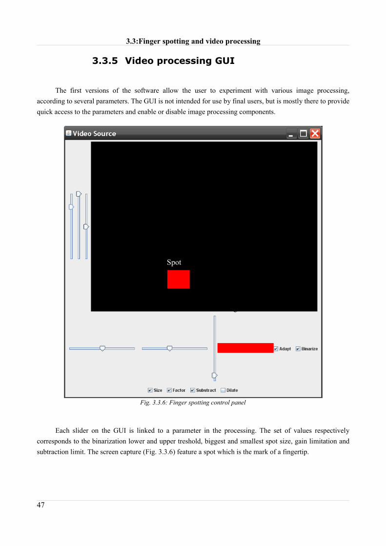
3.3.5 Video processing GUI
The first versions of the software allow the user to experiment with various image processing, according to several parameters. The GUI is not intended for use by final users, but is mostly there to provide quick access to the parameters and enable or disable image processing components.
Each slider on the GUI is linked to a parameter in the processing. The set of values respectively corresponds to the binarization lower and upper treshold, biggest and smallest spot size, gain limitation and subtraction limit. The screen capture (Fig. 3.3.6) feature a spot which is the mark of a fingertip.
47
Fig. 3.3.6: Finger spotting control panel
Spot
Processing values


3.4: The PianoTable
The three previously mentioned components (image processing, graphics and audio) are associated within the PianoTable. After the video initialization, the main program loop starts checking for fingers and playing music accordingly.
3.4.1 Calibration of each Piano key
As explained earlier, it is necessary to calibrate the system so the system knows where the keys are located in the camera coordinates system. Is is not possible to find a linear transformation to go from the computer graphic coordinate system to the camera coordinate system since both depends on the environment.
To make up for that problem, each key has to be calibrated. The class PianoKey contains both the visual representation and the calibration information.
When instantiated, the key will first appear on the screen. The user will then be asked to press on the four corner of the key. These four points form a polygon in the camera coordinate system. Since every subsequent fingertip position will be detected in the camera coordinate system, it is now possible to check whether the fingertip is inside or outside ([17]) the key polygon and then update the state of the key.
49
Fig. 3.4.1: Eventual key shape from the camera Point of view

Chapter 3: Design
3.4.2 Main software loop
If a fingertip is detected inside a PianoKey (isDown==true), the software enters a switch:
switch(state){ case UP: if(true==isdown) state=KeyState.PRESSED; else state=KeyState.UP; break; case PRESSED: if(true==isdown) state=KeyState.DOWN; else state=KeyState.UP; break; case DOWN: if(true==isdown) state=KeyState.DOWN; else state=KeyState.RELEASED; break; case RELEASED: if(true==isdown) state=KeyState.DOWN; else state=KeyState.UP; break; default: break; }
Once all the key are updated and if a key changed its state, the software update the graphics of UP and DOWN keys, start a note for PRESSED keys, stop the note for RELEASED keys.
3.4.3 Stability issues
It occurs that the Spot of a fingertip flickers after image processing (it can be around the size threshold). To make up for this kind of problem, it could be easy to add a number of intermediate state for the key that prevent too short switch from UP to DOWN.
50
Fig. 3.4.2: PianoKey State Diagram

3.5: Implementation
The PianoTable requires a combination of software components:
• Java Development Kit 6.0
• Java Media Framework 1.1.3 Performance pack
Both can be downloaded from the Sun Microsystems website.
The development of this software was done using the Integrated Development Environment Netbeans 5.5. However, it is not a requirement to build the project. To build the project without Netbeans, one can use Ant (target= build then run).
Graphs made using GNU Dia. Image editing with Irfanview.
As a whole, even is all these components are freely available under Linux and other OS, the prototype runs on Windows XP Professional
51


CHAPTER 4: USABILITY EVALUATION AND
CONCLUSION
53


4.1: User Feedback
Building a product is an iterative process [10]. Testing and having feedback from a group of users is very important to detect usability problems and areas of improvement [18]. This kind of testing sometimes involves low-fidelity prototypes (“paper test”) for complicated user interfaces.
Planning a usability test requires considering what type and number of test persons should do the test, and creating a scenario of a realistic interaction situation, which is a list of tasks that the test person is likely to do in an usual confrontation with the final product [18]. During the test, the users are asked to think aloud, while test observers watch and take notes, trying not to interfere with them. Video recording of the performance can be used as a tool for the evaluation of the usability test.
In this study, the usability test has been conducted on a hi-fidelity prototype which was an operating 24 keys virtual piano, and several parameters have been analyzed, both from observations and user feedback. 5 users were asked to perform three tasks:
• Play whichever music tune that they were familiar with, using one finger.
• Try to play intervals, triads and various chords on several positions of the keyboard.
• Cooperate during the calibration processing.
Given the simplicity of the User Interface, only the following information has been told to the users apart of the current test objective:
“This is a touch sensitive surface. You can play piano by applying pressure with your fingertip on any key, and play music accordingly on three octaves.”
4.1.1 Playing a music tune
Most testers played around 10 notes long tunes and then pressed various keys.
Observation showed that the users enjoyed using this input modality. However, they dislike the fact that sometimes it is possible to activate a key by hovering it. After a short time they adopt a hand gesture that minimize accidental key pressure, by keeping the fingers very vertical so they can avoid the problem. They also notice that keys behave differently given their position on the tabletop.
4.1.2 Playing intervals and triads
An interval or a chord is a pressure of two or more keys with a skip between each one.
55

Chapter 4: Usability evaluation and Conclusion
This test is performed to see the users reaction towards multitouch and their reaction when problems occurs. Unfortunately, the test reveals that the system is very likely to detect false positives when chords are played due to the palm of the hand getting closer to the surface. Furthermore, the space between three keys was quite large, 14 cm, so that pressing more than 2 keys required a bit of agility. Users complained about that point, saying that the multitouch is a nice feature but that it is difficult to use without problems.
4.1.3 Calibration procedure
This test is meant to see if the simple calibration procedure could cause problems. They had to press the four corner of the key whenever the operator asked them to.
No major usability problems were detected. The users understood this requirement but say that this procedure takes too long.
4.1.4 Users comments
At the end of the test, the users are asked to give comments and suggestions on the audio quality, global enjoyment of the system, multitouch and major problems they faced. The feedback gathered this way was very consistent, meaning that most comments agreed on the major drawbacks and advantages of the system.
Concerning audio, two people mentioned the latency between a key pressure and the actual piano note. This prevented them from playing faster since they had to wait a bit of time to hear the sound before continuing.
They found the prototype was fun to use, even if four of them mentioned that the problems around the use of multiple keys really needs to be addressed. However, three testers also mentioned their enthusiasm towards the multitouch capabilities of the system.
They also mentioned that they would enjoy a faster calibration procedure even if they were aware that it is a procedure that need to be run once.
56

4.2: Conclusion
This study described a simple, relatively inexpensive and easily scalable technique for enabling multitouch input on a rear-projected tabletop surface. The fingertip recognition engine is an accurate input device fitted for a lot of applications, even if, as is, it is not good enough for playing the piano. The problem of sound latency can be fixed by simply executing the program on a more reactive operating system such as Mac OS X, and the areas of improvement do not discard a more advanced and reliable version of the PianoTable.
However, from this prototype, is is already possible to envision the development of more challenging applications such games or even programs to ease the teaching of piano by combining the multimedia capabilities of the computer to the simplicity of a touch driven interface.
There are plenty of applications that could take advantage of such interfaces. Other projects use multitouch interfaces to build chess boards, drawing applications, and even a virtual DJ timetable. Public enthusiasm seems to follow. When talking about PianoTable, several people made unsolicited references to the “Minority Report” movie, which seems to prove that this is the kind of Human Computer Interaction that users expects from the future.
The recently released Surface from Microsoft, featuring a fully-integrated multitouch system seems to show that the multitouch interface and applications are a very hot topic. It seems that it is only the beginning.
57


BIBLIOGRAPHY
1: Alexandre Fleury, demeTouch: a New Approach to Human Music Interaction, 2007
2: MIDI Manufacturers Association, Complete MIDI 1.0 Detailed Specification,
http://www.midi.org
3: Jeff Han, Multi Touch User Interface Using Frustrated Total Internal Reflection,
http://cs.nyu.edu/~jhan/ftirsense/
4: Kaltenbrunner, Jordà, Geiger, Alonso, The Reactable: A Collaborative Musical Instrument,
2006
5: Music Technology Group, Icelandic singer Björk incorporates the reactable as a key
instrument of her Volta world tour, 2007
6: Scott, S.D., Grant, K.D. and Mandryk, R.L., System Guidelines for co-located,
collaborative work on tabletop display, 2003
7: Larsen, S., Puka Finder, 2005
8: Jensen, Kofod, Righi, 3d interaction on a tabletop display, 2006
9: ISO, 9241-11: Guidance on usability, 1998
10: Preece, Rogers, Sharp, Interaction Design, 2002
11: Bowman, Kruijff, Joseph, LaViola, Pourpyrev, An introduction to 3-d user interface
design, 2001
12: Kenneth Holm Andersen, Thais Holland Mogensen, Lars Peter Thomsen, Impact of
ownership types on objects in a tabletop display system for collaborative work, 2006
13: Miller Puckett, Real Time Audio Synthesis with PureData, http://puredata.info/
59

Bibliography
14: Sun Microsystems, The Java Runtime Environment API,
http://java.sun.com/javase/6/docs/api/
15: Sun Microsystems, Producing MIDI sounds,
http://java.sun.com/developer/JDCTechTips/2003/tt0805.html
16: Sun Microsystems, Inc., Java Media Framework API, http://java.sun.com/products/java-
media/jmf/
17: Sun Microsystems, Insideness detection technique,
http://java.sun.com/j2se/1.5.0/docs/api/java/awt/geom/PathIterator.html#WIND_EVEN_ODD
18: Rubin, Handbook of Usability Testing, 1994
60

FIGURES INDEX
Fig. 1.1.1: Artist Björk uses Reactable at Coachella festival............................................................ 13Fig. 1.1.2: FTIR glass side view [3]...................................................................................................14Fig. 2.1.1: Tabletop, side view, bottom and top projection................................................................19Fig. 2.1.2: Tabletop, Dimensions....................................................................................................... 21Fig. 2.1.3: Tabletop, front view..........................................................................................................21Fig. 2.3.1: View from under the table................................................................................................ 25Fig. 2.3.2: Tabletop setup. View from under the table.......................................................................26Fig. 2.3.3: Tabletop setup, visible red light glow...............................................................................26Fig. 3.1.1: The Java2D coordinate system.........................................................................................36Fig. 3.1.2: The Piano Keyboard.........................................................................................................36Fig. 3.1.3: The projected Piano Keyboard.........................................................................................36Fig. 3.1.4: Visual feedback for key pressure...................................................................................... 37Fig. 3.1.5: Projected visual feedback................................................................................................. 37Fig. 3.1.6: Calibration procedure Pop-Up........................................................................................ 37Fig. 3.1.7: Calibration procedure visual feedback............................................................................ 38Fig. 3.3.1: Below the tabletop, Acquired Image.................................................................................42Fig. 3.3.2: After subtraction of a reference image............................................................................. 43Fig. 3.3.3: Binarization...................................................................................................................... 43Fig. 3.3.4: Spot size filtering.............................................................................................................. 44Fig. 3.3.5: Normalization................................................................................................................... 44Fig. 3.3.6: Finger spotting control panel........................................................................................... 47Fig. 3.4.1: Eventual key shape from the camera Point of view..........................................................49Fig. 3.4.2: PianoKey State Diagram.................................................................................................. 50
61