Murdoch University Engineering Thesis Appendix XI
31
Murdoch University Engineering Thesis 554 | Page WinCC SCADA System via Profibus & OPC by Hao Xu Appendix XI TP 177B 6” Wincc flexible Configuration Instructions Author: Hao Xu Page: p554 - p584 Last modified: 10/11/2013 This is part of the Engineering Thesis “WinCC SCADA System via Profibus & OPC” by Hao Xu.
Transcript of Murdoch University Engineering Thesis Appendix XI
Murdoch University Engineering Thesis
554 | P a g e WinCC SCADA System via Profibus & OPC by Hao Xu
Appendix XI
TP 177B 6” Wincc flexible
Configuration Instructions
Author: Hao Xu
Page: p554 - p584
Last modified: 10/11/2013
This is part of the Engineering Thesis “WinCC SCADA System via Profibus & OPC” by Hao Xu.

Murdoch University Engineering Thesis
555 | P a g e WinCC SCADA System via Profibus & OPC by Hao Xu
Preface This configuration instruction provides a comprehensive description about the functions and configurations of
TP 177B 6” HMI touch panel in WinCC flexible environment. The contents are summarized as follows:
TP 177B 6” communication configuration
TP 177B 6” function description
TIA Portal communication configuration
Prerequisite Background knowledge of PLC operations
Background knowledge of basic electric circuit
Background knowledge of Profibus communication
Completion of Appendix IX “TP 177B 6” System Configuration Instructions”
Resources TP 177B 6” HMI touch panel
CP5611 Profibus interface PCI card
WinCC flexible configuration software
Profibus cable
Profibus DP connector
MPI adaptor
Murdoch University Engineering Thesis
556 | P a g e WinCC SCADA System via Profibus & OPC by Hao Xu
WinCC flexible Communication Configuration (Refer to WinCC flexible section in the thesis report for an overview of the functions and some background
information)
First of all, make sure TP 177B 6” is powered by 24V DC, then connect PLC and TP 177B 6” with Profibus
connectors and also make sure the Profibus signal is terminated properly on each end of the network. Finally,
set the DIP switches at the back of TP 177B 6” to PLC and HMI communication. (Refer to Appendix IX TP 177B 6”
System Configuration Instruction for DIP switch settings)
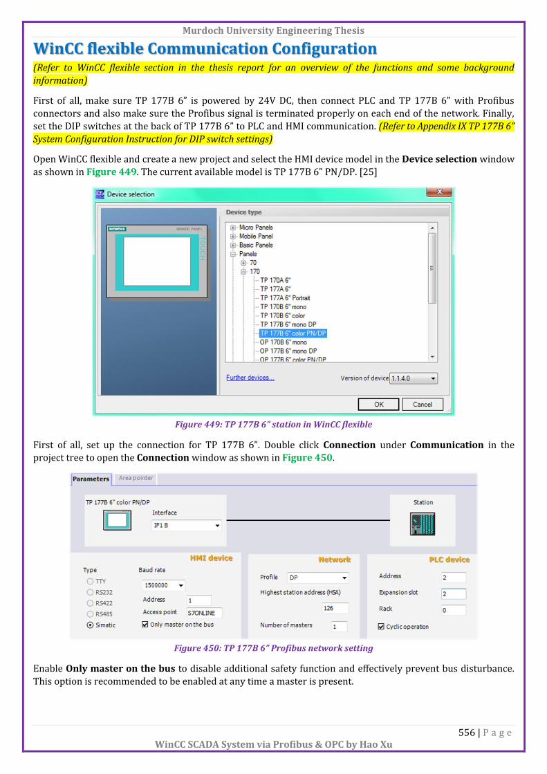
Open WinCC flexible and create a new project and select the HMI device model in the Device selection window
as shown in Figure 449. The current available model is TP 177B 6” PN/DP. [25]
Figure 449: TP 177B 6” station in WinCC flexible
First of all, set up the connection for TP 177B 6”. Double click Connection under Communication in the
project tree to open the Connection window as shown in Figure 450.
Figure 450: TP 177B 6” Profibus network setting
Enable Only master on the bus to disable additional safety function and effectively prevent bus disturbance.
This option is recommended to be enabled at any time a master is present.

Murdoch University Engineering Thesis
557 | P a g e WinCC SCADA System via Profibus & OPC by Hao Xu
Restart TP 177B 6” and on the startup screen, choose Control Panel from the Loader and enter S7-Transfer
Settings as shown in Figure 451.
Figure 451: Loader menu on TP 177B 6” [57]
Select Profibus from the list and click Properties to open up a parameter window (Figure 452). Now set the
parameter the same as the configuration in TIA Portal (Figure 453).
Figure 452: S7-Transfer Settings in the control panel on TP 177B 6” [57]
Figure 453: Profibus network parameter setting in S7-Transfer Settings on TP 177B 6" [57]

Murdoch University Engineering Thesis
558 | P a g e WinCC SCADA System via Profibus & OPC by Hao Xu
On the top left corner of the control panel, File Close to close the control panel and click Transfer from
the loader. A window will appear with the message “Connecting to host” (Figure 454), leave this window open
because it is waiting for WinCC flexible to trigger the transfer signal.
Figure 454: Waiting for download screen on TP 177B 6" [57]
In WinCC flexible, from the toolbar, click Select transfer settings and start transfer to the device to execute
a download command. Select MPI/DP for Mode and enter TP 177B 6” Profibus address then click Transfer
(Figure 455). [63] [75]
Figure 455: Download window in WinCC flexible

Murdoch University Engineering Thesis
559 | P a g e WinCC SCADA System via Profibus & OPC by Hao Xu
Create Screen To create a new screen, double click Add Screen under HMI Screens section in the project tree. To set home
screen, go to Device Settings and select the screen name from the Start screen field as shown in Figure 456.
[64]
Figure 456: Add screen window in WinCC flexible
Bind HMI Tag to PLC variables In order to make the PLC to interact with TP 177B 6”, HMI tags need to bind to PLC variables. Therefore, by
changing the values in HMI tags will also affect the corresponding PLC tags.
Double click Tags under Communication in the project tree to open Tags window and then double click the
blank row to add a new tag. Enter the desired data type and address of the PLC variable as well as the
acquisition cycle as shown in Figure 457. [74]
Figure 457: Link PLC address to HMI tag in WinCC flexible
Murdoch University Engineering Thesis
560 | P a g e WinCC SCADA System via Profibus & OPC by Hao Xu
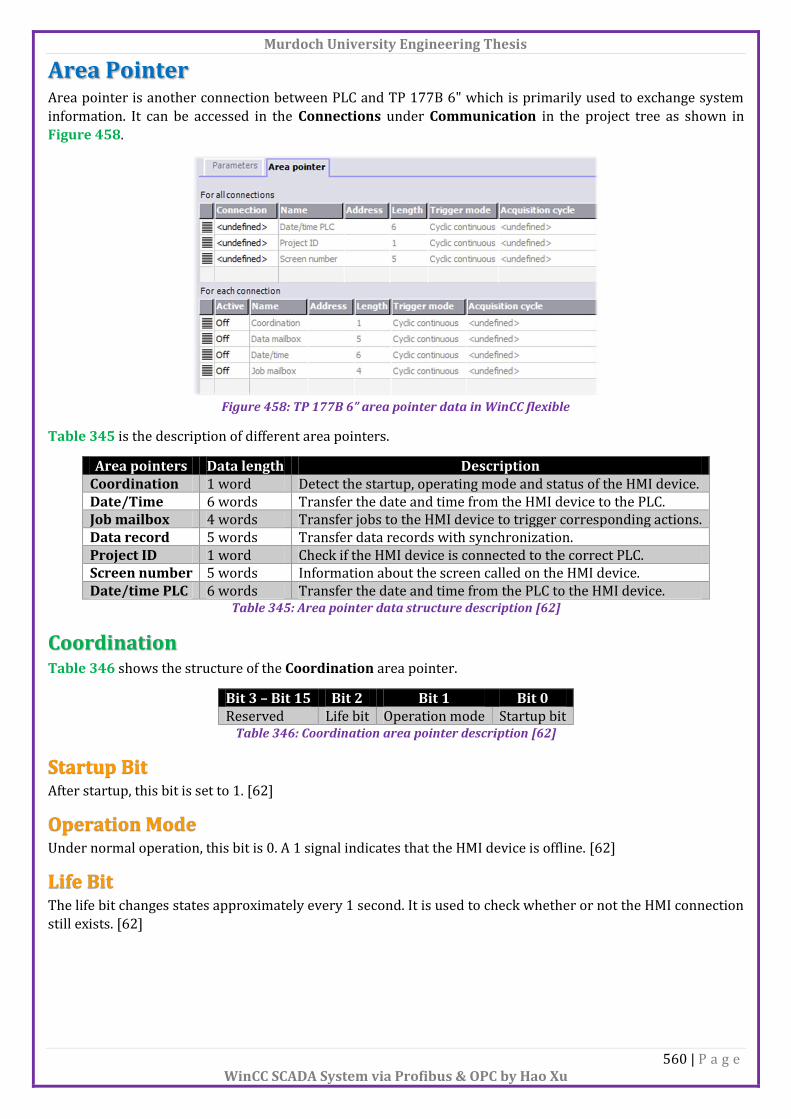
Area Pointer Area pointer is another connection between PLC and TP 177B 6" which is primarily used to exchange system
information. It can be accessed in the Connections under Communication in the project tree as shown in
Figure 458.
Figure 458: TP 177B 6” area pointer data in WinCC flexible
Table 345 is the description of different area pointers.
Area pointers Data length Description Coordination 1 word Detect the startup, operating mode and status of the HMI device. Date/Time 6 words Transfer the date and time from the HMI device to the PLC. Job mailbox 4 words Transfer jobs to the HMI device to trigger corresponding actions. Data record 5 words Transfer data records with synchronization. Project ID 1 word Check if the HMI device is connected to the correct PLC. Screen number 5 words Information about the screen called on the HMI device. Date/time PLC 6 words Transfer the date and time from the PLC to the HMI device.
Table 345: Area pointer data structure description [62]
Coordination Table 346 shows the structure of the Coordination area pointer.
Bit 3 – Bit 15 Bit 2 Bit 1 Bit 0 Reserved Life bit Operation mode Startup bit
Table 346: Coordination area pointer description [62]
Startup Bit After startup, this bit is set to 1. [62]
Operation Mode Under normal operation, this bit is 0. A 1 signal indicates that the HMI device is offline. [62]
Life Bit The life bit changes states approximately every 1 second. It is used to check whether or not the HMI connection
still exists. [62]

Murdoch University Engineering Thesis
561 | P a g e WinCC SCADA System via Profibus & OPC by Hao Xu
Date/Time Table 347 shows the structure of the Data/time area pointer.
Date/time pointers Most significant byte Least significant byte Word 1 Reserved Hour (00 – 23) Word 2 Minute (00 – 59) Second (00 – 59) Word 3 Reserved Reserved Word 4 Reserved Weekday (01 – 07) Word 5 Day (01 - 31) Month (01 – 12) Word 6 Year (80 – 99/00 – 29) Reserved
Table 347: Date/time area pointer description [62]
Job Mailbox Table 348 shows the structure of the Job mailbox area pointer. The first word contains the job number and
the rest words contain parameter depending on the job number (Table 349).
Job mailbox pointer Most significant byte Least significant byte Word 1 0 Job number (See Table 349) Word 2 Parameter 1 Word 3 Parameter 2 Word 4 Parameter 3
Table 348: Job mailbox area pointer description [62]
Job number Parameter 1 Parameter 2 Parameter 3 14 Set time LSB: hours MSB: Minutes
LSB: Seconds N/A
15 Set date LSB: Weekday MSB: Day LSB: Month
MSB: Year
23 User logon Group number N/A N/A 24 User logoff N/A N/A N/A 40 Transfer date/time to PLC N/A N/A N/A 46 Update tags Update ID N/A N/A 49 Clear process alarm buffer N/A N/A N/A 50 Clear alarm buffer N/A N/A N/A 51 Screen selection Screen number N/A Field number 69 Read data record from PLC Recipe number Data record number 0: Do not overwrite
1: Overwrite 70 Write data record to PLC Recipe number Data record number N/A
Table 349: Job number data structure [62]

Murdoch University Engineering Thesis
562 | P a g e WinCC SCADA System via Profibus & OPC by Hao Xu
Data Record Table 350 shows the structure of the Data record area pointer.
Data record pointer Description 1st word Current recipe number. 2nd word Current data record number. 3rd word Reserved. 4th word Status (See Table 351). 5th word Reserved. Table 350: Data record area pointer data structure [62]
Status Description 00 Transfer permitted, data record free. 02 Transfer is busy. 04 Transfer has no error. 0C Transfer has error.
Table 351: Status description of data record area pointer [62]
Project ID To assign a project ID to TP 177B 6”, in the project tree, under Device Settings, double click Device settings,
Runtime settings Project ID (Figure 459)
Figure 459: Project ID setting in WinCC flexible
Screen Number Table 352 shows the structure of the Screen number area pointer.
Screen number pointer Description 1st word Current screen type. 2nd word Current screen number. 3rd word Reserved. 4th word Current field number. 5th word Reserved.
Table 352: Screen number area pointer data structure [62]
Murdoch University Engineering Thesis
563 | P a g e WinCC SCADA System via Profibus & OPC by Hao Xu
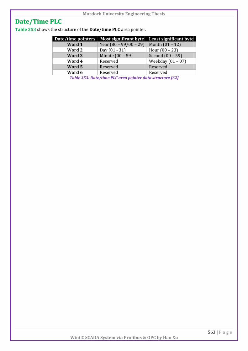
Date/Time PLC Table 353 shows the structure of the Date/time PLC area pointer.
Date/time pointers Most significant byte Least significant byte Word 1 Year (80 – 99/00 – 29) Month (01 – 12) Word 2 Day (01 - 31) Hour (00 – 23) Word 3 Minute (00 – 59) Second (00 – 59) Word 4 Reserved Weekday (01 – 07) Word 5 Reserved Reserved Word 6 Reserved Reserved
Table 353: Date/time PLC area pointer data structure [62]

Murdoch University Engineering Thesis
564 | P a g e WinCC SCADA System via Profibus & OPC by Hao Xu
Cycles Acquisition cycle: Determine the time interval which the HMI device will read the process value from a
variable in the PLC.
The available acquisition cycle times are shown in Figure 460.
Figure 460: Available acquisition cycles of TP 177B 6"
Logging cycle: Determine the time interval which the data will be saved in the log database. The logging cycle
time is always an integer multiple of the acquisition cycle.
Update cycle: Determine the time which the HMI screen will be refreshed.
Linear Scaling To apply a linear scaling between the values in the PLC and TP 177B 6”, Properties Linear scaling. Tick the
Linear scaling tick box and define the scaling details as shown in Figure 461. [74]
Figure 461: Linear scaling between PLC and HMI tags
Connection Types There are basically 2 HMI tag connection types available which are internal connection and customized
connection.
Internal connection: The tags are stored in the memory of TP 177B 6" and can only be read and write
from this HMI device.
Customized connection: Tags are the images of the defined variables in the PLC and user can read and
write to those variables from both TP 177B 6” and the PLC.

Murdoch University Engineering Thesis
565 | P a g e WinCC SCADA System via Profibus & OPC by Hao Xu
Objects
Simple Objects Table 354 summaries the function of simple objects.
Object names Description Line Create a straight line with customized colours and styles. Polyline Create a polyline with customized colours and styles. Polygon Create a polygon with customized colours and styles. Ellipse Create an ellipse with customized colours and styles. Circle Create a circle with customized colours and styles. Rectangle Create a rectangle with customized colours and styles. Text field Create a static text with customized fonts, colours and styles.
Table 354: Simple objects description in WinCC flexible [68] [69]
I/O Field The I/O field is able to read/write value to a tag with pre-defined limits (Figure 462).
Figure 462: I/O field simple object general parameters in WinCC flexible
Type
Input: Allow HMI device to write value.
Output: Allow HMI device to read value.
Input/output: Allow HMI device to read/write value.
Date/Time Field This field is mainly used to display system time (Figure 463).
Figure 463: Date/time field simple object general parameters in WinCC flexible

Murdoch University Engineering Thesis
566 | P a g e WinCC SCADA System via Profibus & OPC by Hao Xu
Graphic I/O Field The Graphic I/O field is able to display a graphic from a graphics list according to the tag value.
In Graphic I/O field, create a HMI tag and bind it to a PLC variable, then select it as the external tag as shown in
Figure 464.
Figure 464: Graphic I/O field simple object general parameters in WinCC flexible
Double click Graphics Lists under Text and Graphics Lists in the project tree to open the Graphics Lists
window (Figure 465) and then double click on the blank row to create a list.
After created the list, allocate graphics according to different value ranges in the List entries below (Figure
465).
Figure 465: Graphics list of graphic I/O field in WinCC flexible
Finally, in the Properties of Graphic I/O field, select the list just created from the Graphics lists. Now
different graphics will be displayed depending on the value of the PLC tag.

Murdoch University Engineering Thesis
567 | P a g e WinCC SCADA System via Profibus & OPC by Hao Xu
Symbolic I/O Field The Symbolic I/O field allows user to output text list entries and user can also choose a text from a text list to
change the content of the field.
Create an Operation Selection Field In a screen view, drag a Symbolic I/O field into the screen and create a HMI tag and bind it to a PLC variable,
then select it as the external tag as shown in Figure 466.
Figure 466: Symbolic I/O field general parameters for an operation selection field in WinCC flexible
Double click Text Lists under Text and Graphics Lists in the project tree to open the Text Lists window, then
double click on the blank row to create a list.
After creating the list, create some value ranges in the List entries below as shown in Figure 467.
Figure 467: Text list setting for operation selection field in WinCC flexible
Finally, in the Properties of Symbolic I/O field, select the list just created from the Text list. Now those values
will be sent to a PLC variable for monitor or control purpose.

Murdoch University Engineering Thesis
568 | P a g e WinCC SCADA System via Profibus & OPC by Hao Xu
Create a Screen Selection Field In a screen view, drag a Symbolic I/O field into the screen then create a HMI tag and select it as the external
tag as shown in Figure 468.
Figure 468: Symbolic I/O field general parameters for a screen selection field in WinCC flexible
In the Events menu, add an ActivateScreenByNumber function to the Change event. Assign the created tag
name to the Screen number and leave 0 for the Object number as shown in Figure 469.
Figure 469: ActivateScreenByNumber function with Change event
Double click Text Lists under Text and Graphics Lists in the project tree to open the Text Lists window and
then double click on the blank row to create a list. After creating the list, create some value ranges in the List
entries below as well (Figure 470).
Figure 470: Text list for screen selection field in WinCC flexible
Finally, in the Properties of Symbolic I/O field, select the list just created from the Text lists. Now user can
navigate between different screens via the Symbolic I/O field.
Murdoch University Engineering Thesis
569 | P a g e WinCC SCADA System via Profibus & OPC by Hao Xu
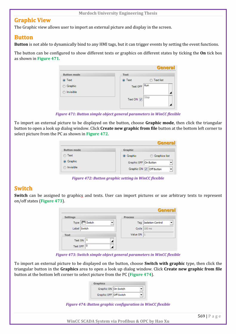
Graphic View The Graphic view allows user to import an external picture and display in the screen.
Button Button is not able to dynamically bind to any HMI tags, but it can trigger events by setting the event functions.
The button can be configured to show different texts or graphics on different states by ticking the On tick box
as shown in Figure 471.
Figure 471: Button simple object general parameters in WinCC flexible
To import an external picture to be displayed on the button, choose Graphic mode, then click the triangular
button to open a look up dialog window. Click Create new graphic from file button at the bottom left corner to
select picture from the PC as shown in Figure 472.
Figure 472: Button graphic setting in WinCC flexible
Switch Switch can be assigned to graphics and texts. User can import pictures or use arbitrary texts to represent
on/off states (Figure 473).
Figure 473: Switch simple object general parameters in WinCC flexible
To import an external picture to be displayed on the button, choose Switch with graphic type, then click the
triangular button in the Graphics area to open a look up dialog window. Click Create new graphic from file
button at the bottom left corner to select picture from the PC (Figure 474).
Figure 474: Button graphic configuration in WinCC flexible

Murdoch University Engineering Thesis
570 | P a g e WinCC SCADA System via Profibus & OPC by Hao Xu
Bar The Bar represents value with a bar graph which allows the user to visualize the process.
The maximum and minimum values of the bar can be bound to 2 HMI tags as shown in Figure 475. If no tags
are bound, they will be using the static values. The actual process value is sent to a HMI tag for monitoring
purpose.
Figure 475: Bar simple object general parameters in WinCC flexible

Murdoch University Engineering Thesis
571 | P a g e WinCC SCADA System via Profibus & OPC by Hao Xu
Enhanced Objects
Slider The Slider is used to control the numeric process value.
The maximum and minimum values of the slider can be bound to 2 HMI tags as shown in Figure 476. If no tags
are bound, they will be using the static values. The actual process value is sent to a HMI tag for control purpose.
Figure 476: Slider enhanced object general parameter in WinCC flexible
Status/Force The Status/Force provides direct read and write access to specific variables in the PLC. To read and write
values on TP 177B 6”, read button and write button on the HMI screen need to be activated respectively as
shown in Figure 477.
Figure 477: Status/Force enhanced object general parameter in WinCC flexible
Connection: Choose the connection with PLC.
Type: Choose the variable types.
DB number: Choose certain DB if accessing DB.
Offset: Choose the address.
Bit: Choose the bit of the offset.
Data type: Choose the data type such as Boolean, Integer, Real, etc.
Format: Choose the data representation such as Hex, Dec and Bin.
Status value: Field displays the current value of the variable.
Control value: Field to enter values to overwrite.
User View User view provides the capability to manage users on the HMI device and allows user to log in for a certain
period. User can make changes to the element values depending on privileges. Only one operator can log in
each time and the second operator will force the previous operator to log off. The administrator login has the
capability to view all the present operators. Enabling Automatic logoff will automatically log off users after the
pre-defined logoff time if no actions were performed.
Murdoch University Engineering Thesis
572 | P a g e WinCC SCADA System via Profibus & OPC by Hao Xu
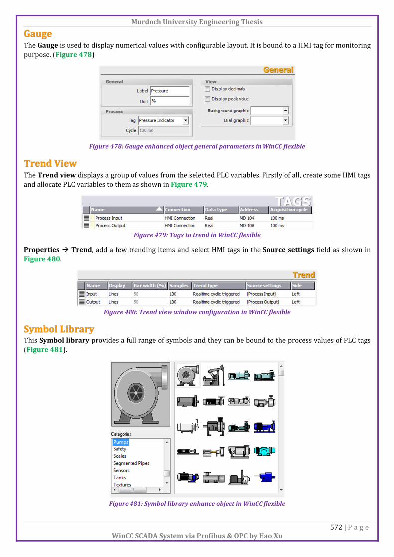
Gauge The Gauge is used to display numerical values with configurable layout. It is bound to a HMI tag for monitoring
purpose. (Figure 478)
Figure 478: Gauge enhanced object general parameters in WinCC flexible
Trend View The Trend view displays a group of values from the selected PLC variables. Firstly of all, create some HMI tags
and allocate PLC variables to them as shown in Figure 479.
Figure 479: Tags to trend in WinCC flexible
Properties Trend, add a few trending items and select HMI tags in the Source settings field as shown in
Figure 480.
Figure 480: Trend view window configuration in WinCC flexible
Symbol Library This Symbol library provides a full range of symbols and they can be bound to the process values of PLC tags
(Figure 481).
Figure 481: Symbol library enhance object in WinCC flexible

Murdoch University Engineering Thesis
573 | P a g e WinCC SCADA System via Profibus & OPC by Hao Xu
Alarm View The Alarm view allows user to view and acknowledge alarms from the process.
There are 3 types of alarms which are discrete alarm, analog alarm and system alarm.
Discrete alarm: The alarm is triggered by the state of a word bit.
Analog alarm: The alarm is triggered by the threshold value of an integer.
System alarm: The alarm is triggered by the internal error in either HMI or PLC during Runtime. [76]
The warnings alarm class cannot be acknowledged and will disappear once the warning condition leaves.
Whereas the errors alarm class will remain in the alarm list until the following conditions are met:
Error condition disappears
Error has been acknowledged
Multiple of errors alarms from a same group only need to be acknowledged once.
When an alarm is triggered, a alarm indicator will be displayed on the scrren. The alarm indicator flashes to
indicate that there is at least one unacknowledged alarm. If the alarm indicator is static, it means that all the
errors alarms are acknowledged, but there is at least one warnings alarm still exists.
Firstly, create HMI tags associated to PLC variables for alarm processing, the data type must be word as shown
in Figure 482.
Figure 482: Alarm word for discrete and analog alarms in WinCC flexible
In the project tree, under Alarm Management, double click Discrete Alarms to open the Discrete Alarms
window. Create a few alarms with different Numbers and both warnings and errors alarm classes are
accepted. [73]
In the Trigger tag field, choose the HMI tag just created and allocate a different Trigger address for each
alarm as shown in Figure 483. Notice that the actual Trigger address of the alarm starts from the 2nd byte of the PLC word. Table 355 illustrates this convention.
Figure 483: Discrete alarm configuration window in WinCC flexible
PLC address HMI triggered address PLC address HMI triggered address M100.0 M101.0 M101.0 M100.0 M100.1 M101.1 M101.1 M100.1 M100.2 M101.2 M101.2 M100.2 M100.3 M101.3 M101.3 M100.3 M100.4 M101.4 M101.4 M100.4 M100.5 M101.5 M101.5 M100.5 M100.6 M101.6 M101.6 M100.6 M100.7 M101.7 M101.7 M100.7
Table 355: Cross reference of PLC and HMI alarm trigger address

Murdoch University Engineering Thesis
574 | P a g e WinCC SCADA System via Profibus & OPC by Hao Xu
In the project tree, under Alarm Management, double click Analog Alarms to open the Analog Alarms
window. Create a few alarms with different Numbers, both warnings and errors alarm classes are accepted.
[73]
In the Trigger tag field, choose the HMI tag just created and select the Trigger mode with an associated
numeric limit as shown in Figure 484.
Figure 484: Analog alarm configuration window in WinCC flexible
In Alarm view, set up the alarm class and the components need to display from Properties General
Display (Figure 485).
Figure 485: Alarm view display settings in WinCC flexible
To set up the tool buttons come with the alarm window, Properties Properties Display (Figure 486).
Figure 486: Alarm view button configuration in WinCC flexible
Infotext: Display the extra information for a particular alarm. The entry of the text can be accessed for
individual alarm from Properties Properties Infotext.
ACK: Acknowledge errors alarm type only.
Edit: Navigate to the screen which contains the tag that trigger the alarm by setting the functions for
Edit event. [66]
Buttonlbar style: With the current HMI device model, the button is the only style.

Murdoch University Engineering Thesis
575 | P a g e WinCC SCADA System via Profibus & OPC by Hao Xu
Properties Properties Columns, set up the visible columns displayed on the alarm window and also the
column properties (Figure 487).
Figure 487: Alarm view visible column configuration in WinCC flexible
Sm@rtClient View The Sm@rtClient view enables user to operate a remote operator station. [65] [78]
Recipe View The Recipe view is used to view and manage data records. [64]

Murdoch University Engineering Thesis
576 | P a g e WinCC SCADA System via Profibus & OPC by Hao Xu
Animations The animation can be applied to most of the objects to achieve a dynamic view on the HMI device. The available
animations are shown in Figure 488.
Figure 488: Animation configuration window in WinCC flexible
Visibility Animation Create a boolean HMI tag in the HMI tag table and bind it to a PLC variable. Then enable Visibility in the
Animations of the object. Select Bit for the Type and Visible for Object state (Figure 489). Now once the
memory bit is on, the object is visible. [28]
Figure 489: Visible animation configuration in WinCC flexible

Murdoch University Engineering Thesis
577 | P a g e WinCC SCADA System via Profibus & OPC by Hao Xu
Events Events are used as triggers to activate certain functions. Depending on the elements, an element can have one
or more events.
Activate: When a button has been activated.
Deactivate: When a button has been deactivated.
OnFinishInput: When a value has been successfully entered.
Click: Single tab with release on the object.
Double-click: Double tabs with release on the object.
Press: When a press is triggered or rising edge.
Release: When a release action is completed or failing edge.
Change: When a value is changed.
Switch ON: When a switch has been switched on.
Switch OFF: When a switch has been switched off.
Loaded: When a screen is loaded.
Cleared: When leaving a screen.
Acknowledge: When acknowledge an alarm.
Edit: When press the loop-in alarm button. [77]
Murdoch University Engineering Thesis
578 | P a g e WinCC SCADA System via Profibus & OPC by Hao Xu
Functions Functions provide various tasks which can be applied to events which greatly increase the functionality of
elements.
Alarms ClearAlarmBuffer: Delete alarms from the buffer on the HMI device.
ClearAlarmBufferProTool: Same as ClearAlarmBufer, but uses the old ProTool numbering.
SetAlarmReportMode: Switch the automatic reporting of alarms on the printer on or off.
ShowAlarmWindow: Show or hide the alarm window on the HMI device.
ShowSystemAlarm: Displays the value of the delivered parameter as a system alarm on the HMI
device.
Calculation Script DecreaseTag: Subtract the given value from the tag values.
IncreaseTag: Add the given value to the value of the tags.
InverseLinearScaling: Assign a value to tag X, which is calculated from the value of the given tag Y
using the linear function X = (Y-b)/a.
LinearScaling: Assign a value to tag Y, which is calculated from the value of the given tag X using the
linear function Y=(a*X)+b.
SetTag: Assign a new value to the given tag.
Edit Bits InvertBit: Invert the value of the given tag of the Boolean type.
InvertBitInTag: Invert a bit in the given tag.
ResetBit: Set the value of a Boolean tag to 0.
ResetBitInTag: Set a bit in the specified tag to 0.
SetBit: Set the value of a Boolean tag to 1.
SetBitInTag: Set a bit in the given tag to 1.
ShiftAndMask: Convert the input bit pattern of the source tag into an output bit pattern of the target
tag.
Keyboard ShowOperatorNotes: Display the configured tooltip of the selected object.
Keyboard Operation for Screen Objects AlarmViewAcknowledgeAlarm: Acknowledge the alarms selected in the given alarm view.
AlarmViewEditAlarm: Trigger the event “Edit” for all alarms selected in the given alarm view.
AlarmViewShowOperatorNotes: Display the configured tooltip of the alarm selected in the given
alarm view.
RecipeViewBack: Return to the previous selection list in the given recipe view.
RecipeViewClearDataRecord: Delete the data record which is currently displayed in the recipe view.
RecipeViewGetDataRecordFromPLC: Transfer the data record that is currently loaded in the PLC to
the HMI device and display it in the recipe view.
RecipeViewMenu: Open the menu of the specified simple recipe view.
RecipeViewNewDataRecord: Create a new data record in the given recipe view.
RecipeViewOpen: Display the data record values in the given recipe view or change to the next
selection field.

Murdoch University Engineering Thesis
579 | P a g e WinCC SCADA System via Profibus & OPC by Hao Xu
RecipeViewRenameDataRecord: Rename the selected data record in the given recipe view.
RecipeViewSaveAsDataRecord: Save the data record currently being displayed in the recipe view
under a new name.
RecipeViewSaveDataRecord: Save the recipe data record which is currently displayed in the recipe
view.
RecipeViewSetDataRecordToPLC: Transfer the recipe data record which is currently displayed in the
recipe view to the PLC.
RecipeViewShowOperatorNotes: Display the configured tooltip of the specified recipe view.
RecipeViewSynchronizeDataRecordWithTags: Synchronize the values of the data record which is
currently displayed in the recipe view with their recipe tags.
ScreenObjectCursorDown: Result in a line-by-line, downward cursor movement in the specified
screen object.
ScreenObjectCursorUp: Result in a line-by-line, upward cursor movement in the specified screen
object.
ScreenObjectPageDown: Result in a page-by-page, downward cursor movement in the specified
screen object.
ScreenObjectPageUp: Result in a page-by-page, upward cursor movement in the specified screen
object.
SmartClientViewConnect: Execute the “Connect” command in the Sm@rtClient view.
SmartClientViewDisconnect: Execute “Disconnect ” command in the Sm@rtClient view.
SmartClientViewLeave: Exit the Sm@rtClient view and return to the operation of the HMI device.
SmartClientViewReadOnlyOff: Set read only access to “Off” in the Sm@rtClient view.
SmartClientViewReadOnlyOn: Set read only access to “On” in the Sm@rtClient view.
SmartClientViewRefresh: Update the contents displayed in the Sm@rtClient view.
StatusForceGetValues: Start or stop the updating of values in the Status/Force display.
StatusForceSetValues: Write values from the Status/Force display to the PLC to which the HMI device
is connected.
TrendViewBackToBeginning: Scroll back to the beginning of the display range in the trend view.
TrendViewCompress: Increase the time period which is displayed in the trend view.
TrendViewExtend: Reduce the time period which is displayed in the trend view.
TrendViewRulerLeft: Move the read-line backwards to the trend view.
TrendViewRulerRight: Move the read-line forwards in the trend view.
TrendViewScrollBack: Scroll back one display width to the left in the trend view.
TrendViewScrollForward: Scroll forward one display width in the trend view.
TrendViewSetRulerMode: Show or hide the read-line in the trend view.
TrendViewStartStop: Stop the trend recording or continue the trend recording in the trend view.
UpdataView: Update the enhanced alarm view.
Other Functions ControlSmartServer: Start or stop the Sm@rtServer.
ControlWebServer: Start or stop the web server.
Encode: Adapt the “String” data type of a tag for transfer to the automation system (AS).
EncodeEx: Same as Encode, but can define the line break parameter.
LookupText: Identify an entry from a text list.
OpenInternetExplorer: Open the Internet Explorer on the HMI device.
SendEmail: Send an e-mail from the HMI device to the given address.
StopRuntime: Exit the runtime software and thereby the project running on the HMI device.

Murdoch University Engineering Thesis
580 | P a g e WinCC SCADA System via Profibus & OPC by Hao Xu
Print PrintReport: Print the given report from the printer which is connected to the HMI device.
PrintScreen: Print the currently displayed screen on the HMI device from the printer which is
connected to the HMI device.
SetAlarmReportMode: Switch the automatic reporting of alarms on the printer on or off.
Recipes ClearDataRecord: Delete a recipe data record.
ClearDataRecordMemory: Delete all recipes and recipe data records from the specified storage
medium.
ExportDataRecords: Export one or all data records of a recipe to a CSV file.
GetDataRecordFromPLC: Transfer the given recipe data record from the PLC to the memory medium
of the HMI device.
GetDataRecordName: Write the name of the given recipe and recipe data record to the given tags.
GetDataRecordTagsFromPLC: Transfer the values of the recipe data record, which is loaded in the
PLC, to the recipe tag.
ImprotDataRecords: Import one or all data records of a recipe from a CSV file.
LoadDataRecord: Load the given recipe data record from the memory medium of the HMI device in the
recipe tags.
SaveDataRecord: Save the current values of the recipe tags as data record to the memory medium of
the HMI device.
SetDataRecordTagsToPLC: Transfer the values of the recipe tags to the PLC.
SetDataRecordToPLC: Transfer the given recipe data record directly from the data medium of the HMI
device to the PLC with which the HMI device is connected.
SetRecipeTags: Change the status of the recipe tags from “Online” to “Offline” and vice versa.
Screens ActivatePreviousScreen: Perform a screen change to the screen which was activated before the
current screen.
ActivateScreen: Perform a screen change to the given screen.
ActivateScreenByNumber: Perform a screen change to a screen depending on a tag value.
Settings ChangeConnection: Disconnect the connection to the currently used PLC and establish a connection to
a PLC with another address.
SetConnectionMode: Connect or disconnect the given connection.
SetDeviceMode: Toggle the operating mode on the HMI device.
SetLanguage: Toggle the language on the HMI device.
SetWebAccess: Determine the access mode to the Runtime application using the Internet.
System ActivateCleanScreen: Activate the clean screen on the HMI device.
AdjustContrast: Change the contrast of the display one level on the HMI device.
CalibrateTouchScreen: Call a program for calibrating the touch screen.
OpenControlPanel: Open a window which displays the Windows CE control panel.
Murdoch University Engineering Thesis
581 | P a g e WinCC SCADA System via Profibus & OPC by Hao Xu
User Administration ExportImportUserAdministration: Export all users of the user administration of the currently active
project to the given file or import the users from the given file into the currently active project.
GetGroupNumber: Read the number of the groups to which the user logged on to the HMI device
belongs, and write it to the given tag.
GetPassword: Write the password of the user currently logged on to the HMI device in the given tag.
GetUserName: Write the user name of the user currently logged on to the HMI device in the given tag.
Logoff: Log off the current user on the HMI device.
Logon: Log on the current user on the HMI device.
ShowLogonDialog : Open a dialog on the HMI device with which the user can log on to it. [77]

Murdoch University Engineering Thesis
582 | P a g e WinCC SCADA System via Profibus & OPC by Hao Xu
User Administration User administration allows user to create new users, groups and authorizations. A user belongs to a group
and a group can have multiple authorizations. [66] [72]
Figure 490: Users configuration window in WinCC flexible
Figure 491: Groups configuration window in WinCC flexible
Figure 492: Group authorizations configuration window in WinCC flexible
Privilege can be assigned to every element in Security from Properties as shown in Figure 493. After the
privilege is applied to a element, user needs to log in to modify element values each time. Alternatively, user
can log in from the User view which avoids login for each modification. [72]
Figure 493: Runtime security configuration window in WinCC flexible

Murdoch University Engineering Thesis
583 | P a g e WinCC SCADA System via Profibus & OPC by Hao Xu
Runtime Simulation The Runtime simulation provides a fast way to test the HMI screen configuration and also has the capability to
monitor and modify the HMI tag values. To start simulation, click Start runtime system from the toolbar. Click
Start runtime system with simulator to open a tag watch table. [28] [64] [71]
Figure 494: HMI Runtime simulation startup
While choosing With tag simulator, a tag watch table will pop up as shown in Figure 495. Tick the tick box in
the Start column to activate certain tag and enter the value in Set value column to modify the value. [28] [64]
[71]
Figure 495: Simulation tag window in WinCC flexible

Murdoch University Engineering Thesis
584 | P a g e WinCC SCADA System via Profibus & OPC by Hao Xu
This is the end of Appendix XI.