PETRA Usage in Large, Multiuser Environments … Usage in Large, Multiuser Environments
Upload
sarathprasad-k-vCategory
view
18.120download
6
1
Federal Institite Of Science And technology (FISAT),
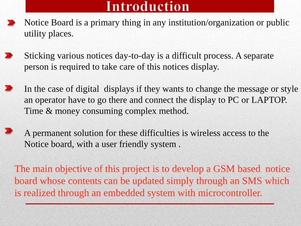
Notice Board is a primary thing in any institution/organization or public
utility places.
Sticking various notices day-to-day is a difficult process. A separate
person is required to take care of this notices display.
In the case of digital displays if they wants to change the message or style
an operator have to go there and connect the display to PC or LAPTOP.
Time & money consuming complex method.
A permanent solution for these difficulties is wireless access to the
Notice board, with a user friendly system .
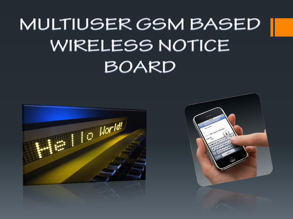
The main objective of this project is to develop a GSM based notice
board whose contents can be updated simply through an SMS which
is realized through an embedded system with microcontroller.

Why GSM ?
GSM(Global System for Mobile Communication) is globally
accessed by more than 212 countries and territories.
It’s one of the fastest growing telecommunication technologies of the world
Short Message Service is a most commonly used communication technique.
Offers very much data secuirity than any other wireless transmission.
Overall functioning:

Notice Board is primary thing in any institution / organization or public utility places like bus stations, railway stations and parks. But sticking various notices day-to-day is a difficult process. Wireless communication has announced its arrival on big stage and the world is going mobile. As we wish to control everything and without moving an inch, notice board need to have wireless access. In present digitalized world, the exploit of GSM and SMS is popular.A new display using the GSM technology to access it by communication between microcontroller and mobile would be effective. So we come to the conclusion to design a GSM based Notice board such that it can fulfill the requirements such as less manual operation, same notice can be displayed at the various places at the same time, compact and compatible, easy handling etc.

The components required for the application are readily available at pocket friendly prices .
Using GSM mobile we can send message to any distant locations , from any part of the World.
As it's a GSM wireless transmission system it has very less errors and needs less maintenance.
Prevents unauthorized access of notice board (password) Gsm wireless transmission offers higher secuirity to the transmitting data.
Multiple Users are authorized to update notices on the electronic notice board
No printing and photocopying costs. Thus saves time,Energy and finally environment.
Problem related to direct manual update of notice board is removed. Just an SMS is enough.
Notifications can be delivered within seconds
.

Educational institutions
& organizations
Managing traffic
Advertisement
Conference hall
Bus/Railway station
Any Public utility places
A P P L I C A T I O N S :

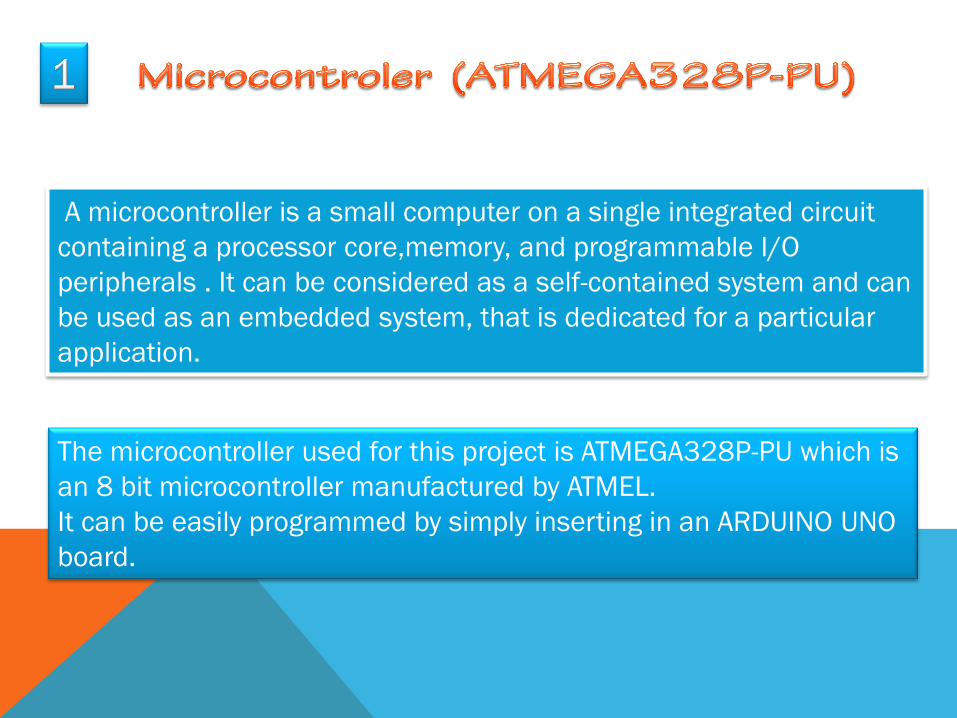
A microcontroller is a small computer on a single integrated circuit
containing a processor core,memory, and programmable I/O
peripherals . It can be considered as a self-contained system and can
be used as an embedded system, that is dedicated for a particular
application.
The microcontroller used for this project is ATMEGA328P-PU which is
an 8 bit microcontroller manufactured by ATMEL.
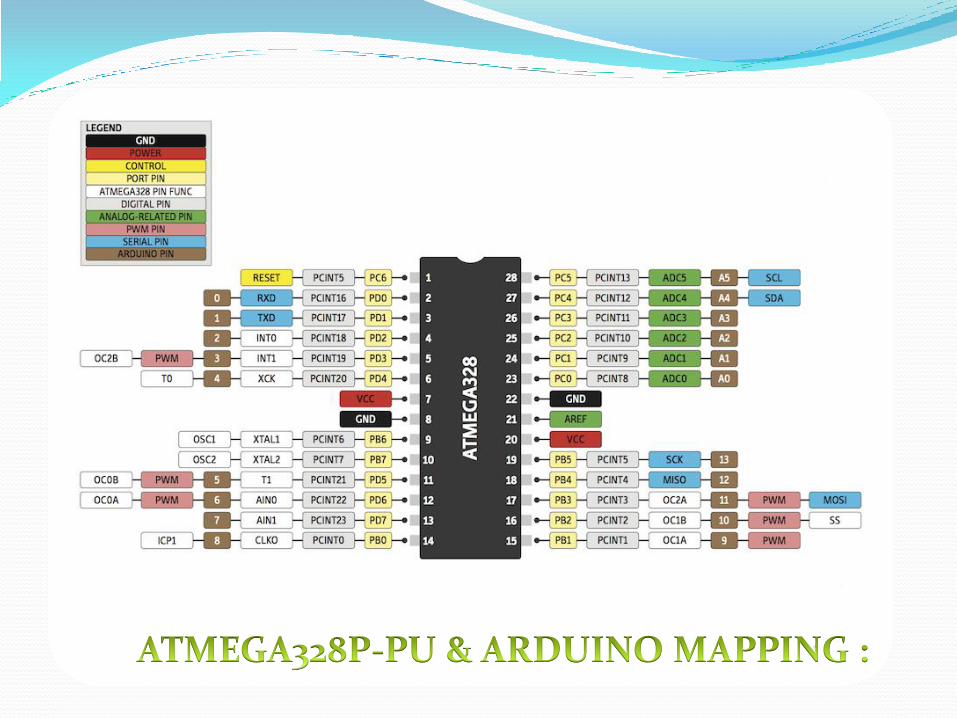
It can be easily programmed by simply inserting in an ARDUINO UNO
board.
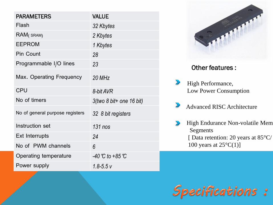
PARAMETERS VALUE
Flash 32 Kbytes
RAM( SRAM) 2 Kbytes
EEPROM 1 Kbytes
Pin Count 28
Programmable I/O lines 23
Max. Operating Frequency 20 MHz
CPU 8-bit AVR
No of timers 3(two 8 bit+ one 16 bit)
No of general purpose registers 32 8 bit registers
Instruction set 131 nos
Ext Interrupts 24
No of PWM channels 6
Operating temperature -40°C to +85°C
Power supply 1.8-5.5 v
Advanced RISC Architecture
High Endurance Non-volatile Memory
Segments
[ Data retention: 20 years at 85°C/
100 years at 25°C(1)]
High Performance,
Low Power Consumption
Other features :
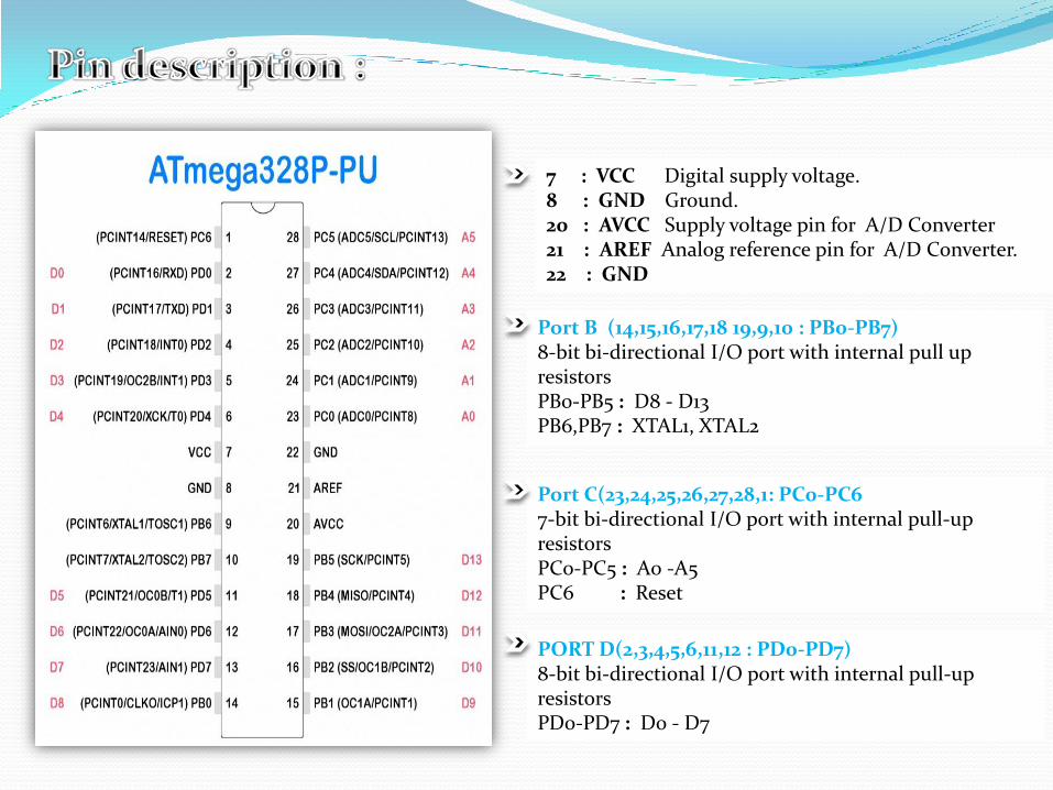
7 : VCC Digital supply voltage. 8 : GND Ground. 20 : AVCC Supply voltage pin for A/D Converter 21 : AREF Analog reference pin for A/D Converter. 22 : GND
Port B (14,15,16,17,18 19,9,10 : PB0-PB7) 8-bit bi-directional I/O port with internal pull up resistors PB0-PB5 : D8 - D13 PB6,PB7 : XTAL1, XTAL2
Port C(23,24,25,26,27,28,1: PC0-PC6 7-bit bi-directional I/O port with internal pull-up resistors PC0-PC5 : A0 -A5 PC6 : Reset
PORT D(2,3,4,5,6,11,12 : PD0-PD7) 8-bit bi-directional I/O port with internal pull-up resistors PD0-PD7 : D0 - D7

A GSM modem is a wireless modem that works with a GSM wireless network.
It is a specialized type of modem which accepts a SIM card, and operates
over a subscription to a mobile operator, just like a mobile.
Here SIM 900 GSM/GPRS TTL UART Modem is used which is built with Quad Band
GSM/GPRS engine.The Modem is coming with selectable interfacing voltage,which
allows to connect 5V & 3V3 microcontroller directly without any level conversion chips.
GSM (Global System for Mobile Communications) , is
a standard developed by the European
Telecommunications Standards Institute (ETSI) to
describe protocols for second generation (2G) digital
cellular networks used by mobile phones.
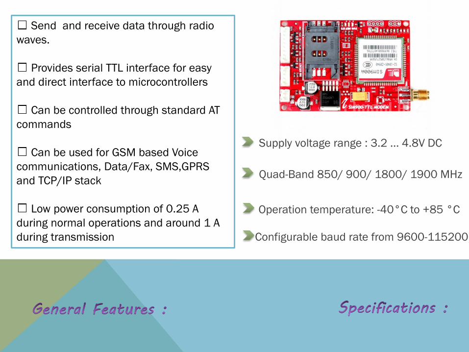
Send and receive data through radio
waves.
Provides serial TTL interface for easy
and direct interface to microcontrollers
Can be controlled through standard AT
commands
Can be used for GSM based Voice
communications, Data/Fax, SMS,GPRS
and TCP/IP stack
Low power consumption of 0.25 A
during normal operations and around 1 A
during transmission Configurable baud rate from 9600-115200).
Operation temperature: -40°C to +85 °C
Supply voltage range : 3.2 ... 4.8V DC
Quad-Band 850/ 900/ 1800/ 1900 MHz

PIN PIN NAME DETAILS
VIN Power Supply Power Supply Input (4.2-13V DC,1A)
GND Ground Ground Level of Power Supply
V_ Interface
Interfacing Voltage
5V DC for interface with 5v µC 3.3V DC for interfacewith 3V3 µC
TXD Transmit Outputs data bytes at voltage Level same as the V_Interface Pin – Usually connected to the Rx pin of the microcontroller
RXD Receive Receives data bytes at voltage Level same as the V_Interface Pin – Usually connected to the TX pin of the microcontroller
GND Ground Ground Level of Interfacing Signals
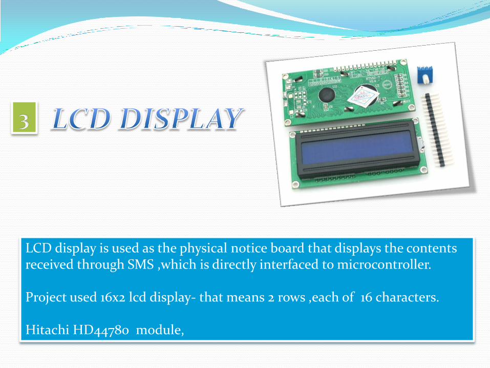
LCD display is used as the physical notice board that displays the contents received through SMS ,which is directly interfaced to microcontroller. Project used 16x2 lcd display- that means 2 rows ,each of 16 characters. Hitachi HD44780 module,

Features Consist of 16 pins including 2 pins for led back light.
Works over 5v Dc power supply
The LCDs have a parallel interface, meaning that the microcontroller has to manipulate several interface pins at once to control the display
Alphanumeric dot matrix display is capable of displaying 224 different characters and symbols.
Are used in palmtop computers, word processors, photocopiers, point of sale terminals, medical instruments, cellular phones, etc.
This will work in 4 bit and 8 bit mode,we are configuring LCD in 4bit mode using Arduino Liquid Crystal Library.
7 I/O pins
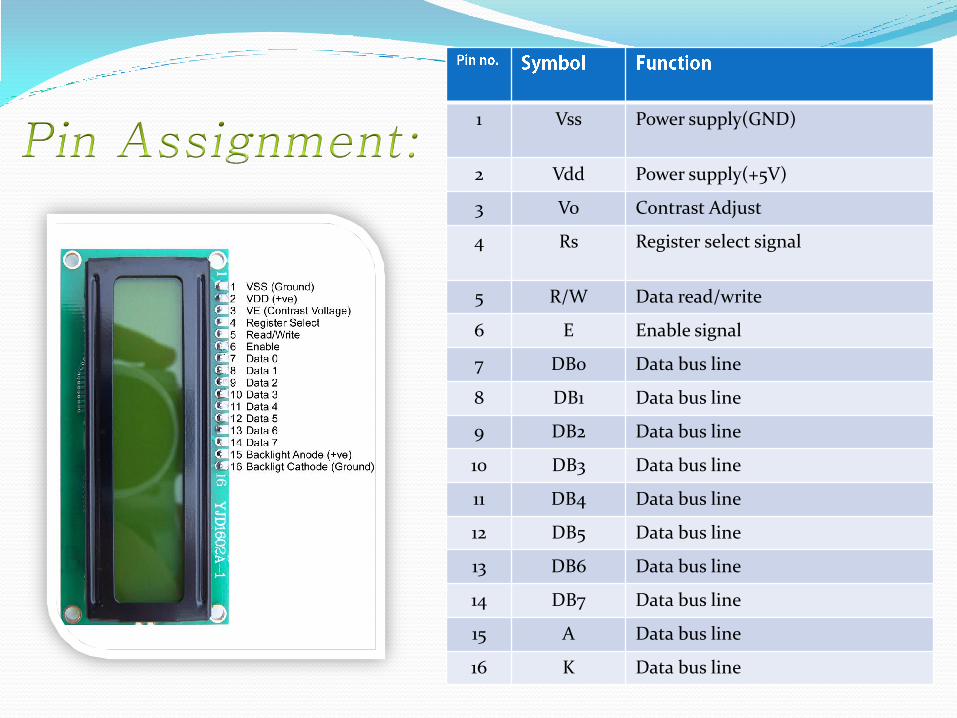
1 Vss Power supply(GND)
2 Vdd Power supply(+5V)
3 Vo Contrast Adjust
4 Rs Register select signal
5 R/W Data read/write
6 E Enable signal
7 DB0 Data bus line
8 DB1 Data bus line
9 DB2 Data bus line
10 DB3 Data bus line
11 DB4 Data bus line
12 DB5 Data bus line
13 DB6 Data bus line
14 DB7 Data bus line
15 A Data bus line
16 K Data bus line


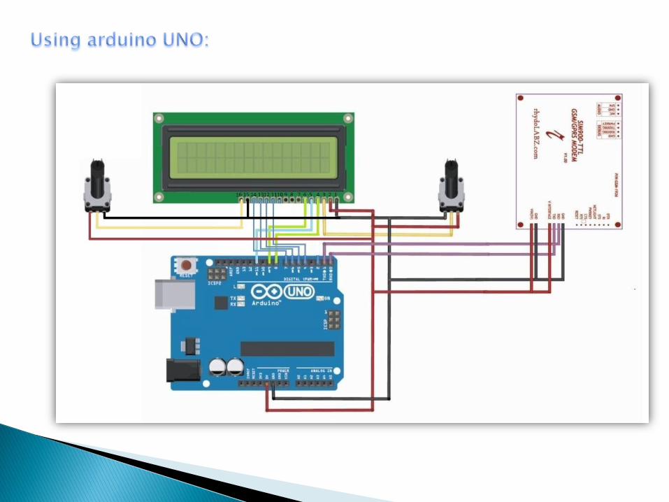
The Arduino Uno is a variety of arduino board based on the ATmega328 .
ARDUINO is an open-source physical computing platform
based on a simple microcontroller board, and a
development environment for writing software for it.
Can be used to develop interactive objects, taking inputs from a variety of
switches or sensors, and controlling a variety of physical outputs.
Has 14 digital input/output pins (of which 6 can be used as PWM outputs), 6
analog inputs, a 16 MHz ceramic resonator, a USB connection, a power jack, an
ICSP header, and a reset button.
The Arduino programming language is an implementation of Wiring, a similar
physical computing platform, which is based on the Processing multimedia
programming environment.
The microcontroller inserted in the arduino board can be easily programmed by
simply uploading the program using IDE software.

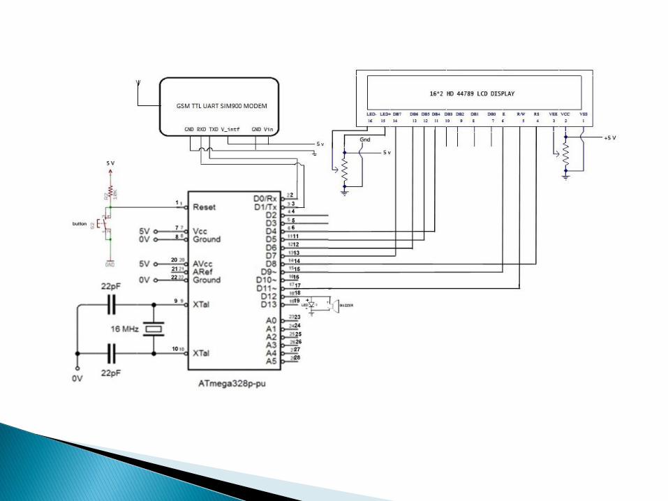

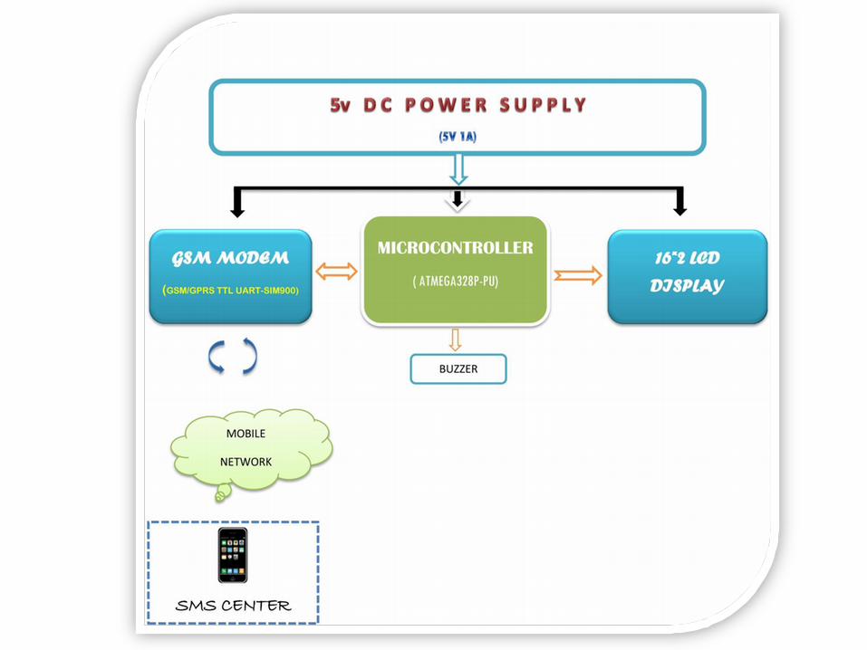
The circuit mainly consists of Microcontroler , LCD display, Gsm modem, necessary resistors, capacitors, pots, crystal oscillator & an External DC Power supply The microcontroller used here is ATMEGA328P-PU which is interfaced with 16*2 lcd as well as GSM Modem. 5v dc power supply is given to the µc with necessary clock pulse of 16 Mhz given using crystal oscillator. Reset button can be used to clear registers and to execute program from beginning. 16*2 LCD display is used for displaying data received through a valid SMS. 5V DC power supply is given fo both LCD and backlight. Two 10k pots are used, one two adjust the contrast and another to control the brightness Of LED backlight. Here LCD is working in 4-bit mode that requires seven I/O pins from the µc ( 4 data lines ,RS ,R/W,ENABLE . For reading or writing data to the display, logic1 is set to RS pin and 1,0 respectively to the R/W pin.

GSM GPRS TTL UART MODEM-SIM900 is powered with 5v Dc. 5v dc is given also to the Vinterface pin for proper interfacing with µc. The serial communication is accomplished between Modem and µc through RX,TX pins. TXD pin of modem is connected to the Rx (2) pin of µc and RXD of modem to the Tx(3) of µc. GSM modem is configured and processed through a set of AT commands. The µc is progammed in such a manner that it gives necessary AT commands to the modem for initialization,sim registration,reading the incoming sms, sending reply to the users etc.

The system has worked successfully and delivered the necessary output as expected

POWER ON
• Initializes LCD
• MODEM Initialization Modem search Cpin verification SIM registration
• Shows the status of all processes on LCD
SMS
• µC waits for a new message from GSM modem
• Format : *GNB<space>content#
IF TRUE
• Indicates the arrival of information through one Buzzer & Blinking LED light
• Prints the content on 1st row of lcd
• Prints NAME of sender in second row if the sender's number is present in our contact list. Otherwise prints senders NUMBERitself
• Sends reply to sender "NAME,Your message is received and displayed in LCD,THANK YOU :)". NAME will be added only if it is present in our contact list
IF FALSE • No change to the notice board.
• Sends reply to the sender "INVALID PASSWORD !!! sorry cannot access the notice board"
FUTURE SCOPES :
Temperature and time (RTC ) display during periods when no messages are
to be displayed.
Multilingual display in different areas as per the local language. This feature can
be added by programming the microcontroller to use different encoding decoding
schemes
The large LED scrolling display can replace small LCD panel in which
multiple messages can be displayed.
Graphical display. MMS technology with relatively high end microcontrollers to
carry on the tasks of graphics encoding and decoding execute it .
Use of multiple modems with displays with duplicate SIMs to increase degree of
broadcasting.
GSM based home security system, GSM based robot control, GSM based DC
motor controller,GSM based stepper motor controller, GSM based voting machine
control etc