MULTISERVICE HELICOPTER SLING LOAD: SINGLE-POINT … · SINGLE-POINT RIGGING PROCEDURES ... M200A1...
101
HEADQUARTERS DEPARTMENT OF THE ARMY UNITED STATES MARINE CORPS DEPARTMENT OF THE NAVY DEPARTMENT OF THE AIR FORCE Change 1 UNITED STATES COAST GUARD Washington, DC, 1 February 2000 MULTISERVICE HELICOPTER SLING LOAD: SINGLE-POINT RIGGING PROCEDURES 1. In this change the name US Army Natick Research, Development, and Engineering Center has been replaced with US Army Soldiers System Center. 2. Change FM 10-450-4, 30 May 1998, as follows: Remove old pages Insert new pages iii through x iii through xi 2-1 and 2-2 2-1 and 2-2 2-21 through 2-26 2-21 through 2-26 2-47 through 2-64 3-1 through 3-4 3-1 through 3-4 3-41 through 3-52 5-1 through 5-7 5-1 through 5-7 6-13 through 6-18 6-13 through 6-18 8-1 and 8-2 8-1 and 8-2 8-77 and 8-78 8-77 through 8-82 11-1 and 11-2 11-1 and 11-2 11-5 through 11-8 11-5 through 11-8 11-15 through 11-20 12-1 and 12-2 12-1 and 12-2 12-23 and 12-24 Appendix A Appendix A Glossary-1 and Glossary-2 Glossary-1 and Glossary-2 References-1 References-1 3. New or changed material is identified by a vertical bar in the margin opposite the changed material. 4. File this transmittal sheet in the front of the publication. DISTRIBUTION RESTRICTION: Approved for public release; distribution is unlimited. C1, FM 10-450-4/MCRP 4-23E, VOL II/NWP 3-04.12/AFJMAN 11-223, VOL II/ COMDTINST M13482.3A
Transcript of MULTISERVICE HELICOPTER SLING LOAD: SINGLE-POINT … · SINGLE-POINT RIGGING PROCEDURES ... M200A1...
HEADQUARTERSDEPARTMENT OF THE ARMY
UNITED STATES MARINE CORPSDEPARTMENT OF THE NAVY
DEPARTMENT OF THE AIR FORCEChange 1 UNITED STATES COAST GUARD
Washington, DC, 1 February 2000
MULTISERVICE HELICOPTER SLING LOAD:SINGLE-POINT RIGGING PROCEDURES
1. In this change the name US Army Natick Research, Development, and Engineering Center has been replacedwith US Army Soldiers System Center.
2. Change FM 10-450-4, 30 May 1998, as follows:
Remove old pages Insert new pages
iii through x iii through xi2-1 and 2-2 2-1 and 2-22-21 through 2-26 2-21 through 2-26
2-47 through 2-643-1 through 3-4 3-1 through 3-4
3-41 through 3-525-1 through 5-7 5-1 through 5-76-13 through 6-18 6-13 through 6-188-1 and 8-2 8-1 and 8-28-77 and 8-78 8-77 through 8-8211-1 and 11-2 11-1 and 11-211-5 through 11-8 11-5 through 11-8
11-15 through 11-2012-1 and 12-2 12-1 and 12-2
12-23 and 12-24Appendix A Appendix AGlossary-1 and Glossary-2 Glossary-1 and Glossary-2References-1 References-1
3. New or changed material is identified by a vertical bar in the margin opposite the changed material.
4. File this transmittal sheet in the front of the publication.
DISTRIBUTION RESTRICTION: Approved for public release; distribution is unlimited.
C1, FM 10-450-4/MCRP 4-23E, VOL II/NWP 3-04.12/AFJMAN 11-223, VOL II/COMDTINST M13482.3A
TABLE OF CONTENTS
Paragraph Page
PREFACE i
CHAPTER 1 FUNDAMENTAL PRINCIPLES
Introduction.............................................................................................. 1-1 1-1Classification Definitions of Sling Loads .............................................. 1-2 1-1Certification of Equipment for Helicopter Sling Load .......................... 1-3 1-1Requests for Sling Load Certification ................................................... 1-4 1-2Unique Items of Equipment or Operational Requirements .................... 1-5 1-2Equipment Rigging Procedures ............................................................... 1-6 1-3General Rigging Instructions ................................................................... 1-7 1-4
CHAPTER 2 CERTIFIED SINGLE-POINT RIGGING PROCEDURES FORWHEELED VEHICLES
Introduction.............................................................................................. 2-1 2-1M996/M997/M997A2 Truck, Ambulance, (HMMWV) ......................... 2-2 2-1M996/M1036/M1045/M1045A2/M1046 TOW Missile Carrier(HMMWV), M1025/M1025A2/M1026/M1043/M1043A2/M1044Armament Carrier (HMMWV)................................................................ 2-3 2-4M998/M1037 Modified (GVW 9,400 lbs)/M1038/M1097/M1097A2Truck, Cargo,1 1/4-ton (HMMWV) ........................................................ 2-4 2-7M1037/M1042 Shelter Carrier (HMMWV) Without Shelter ............... 2-5 2-10M1037/M1042 Shelter Carrier (HMMWV) With S-250 or S-250EShelter...................................................................................................... 2-6 2-12M/1097 Shelter Carrier, Heavy HMMWV, With S-250 or S-250EShelter...................................................................................................... 2-7 2-15M1037 Shelter Carrier (Heavy HMMWV) with Downsized DirectSupport Section (DDSS) Shelter ............................................................. 2-8 2-18M1037 Shelter Carrier (HMMWV) With S-318 Shelter ....................... 2-9 2-20M1097/M1097A2 Shelter Carrier (HMMWV) With LightweightMultipurpose Shelter (LMS) ..................................................................2-10 2-22M1037/M1042 Shelter Carrier (HMMWV) With LightweightMultipurpose Shelter (LMS) .................................................................. 2-11 2-26M1037/M1097 Shelter Carrier (HMMWV) With G15840 SmokeGenerator Set, M157/M157A1E1 .........................................................2-12 2-28M998 (HMMWV) With Two MRC-127 Stacks ....................................2-13 2-30M998/M1038 (HMMWV) With Lightweight Tactical Fire ControlSystems (LTACFIRE)/Tactical Terminal Control System (TTCS) .........2-14 2-32M1037 (HMMWV) With AN/TPQ-36 Firefinder Generator Pallet .....2-15 2-34M1097 (H-HMMWV) With Antenna AS-3036/TSC on OA-9134/TSCPallet Group ............................................................................................2-16 2-36
iii
C1, FM 10-450-4/MCRP 4-23E, VOL II/NWP 3-04.12/AFJMAN 11-223, VOL II/COMDTINST M13482.3A
Paragraph Page
C1, FM 10-450-4/MCRP 4-23E, VOL II/NWP 3-04.12/AFJMAN 11-223, VOL II/COMDTINST M13482.3A
iv
M1097 (H-HMMWV) With High Mobility Digital Group Multiplexer(DGM) Auxiliary Equipment Transportation Container (AETC) in2 and 3 Mast Configurations ..................................................................2-17 2-38M1097 (H-HMMWV) With Cargo Bed Cover (CBC) Aluminum orFiberglass ................................................................................................2-18 2-41Light Armored Vehicle (LAV) (USMC) .................................................2-19 2-44M1097 (H-HMMWV) With AN/TPQ-42, Meteorological HydrogenGenerator (MHG) ...................................................................................2-20 2-46M1097/M1113 Shelter Carrier (HMMWV) With Gitchner Model1497A Shelter .........................................................................................2-21 2-48M1097 (HMMWV) With Contact Maintenance Truck, Heavy(CMTH)...................................................................................................2-22 2-51M1097 (HMMWV) With Enhanced Fiber Optic Guided Missile(EFOGM) Launcher ................................................................................2-23 2-53M1097 (HMMWV) With Sentinel AN/MPQ-64 Tactical QuietGenerator (TQG) ....................................................................................2-24 2-55M1097A2 (HMMWV) With Secure Mobile Anti-Jam TacticalTerminal (SMART-T) Pallet ...................................................................2-25 2-57M1097A1 (HMMWV) With Remote Landing Site Tower (RLST).............2-26 2-59M1113 (HMMWV) With M56 Smoke Generating System........................2-27 2-61M1097A2 (HMMWV) Soft Top Truck With Advanced FieldArtillery Tactical Data Systems (AFATADS) ..........................................2-28 2-63
CHAPTER 3 CERTIFIED SINGLE-POINT RIGGING PROCEDURES FOR TRAILERS
Introduction.............................................................................................. 3-1 3-1M416 1/4-Ton Trailer .............................................................................. 3-2 3-1M101A2/A3 3/4-Ton Trailer ................................................................... 3-3 3-3M1048/M1073 Trailer............................................................................ 3-4 3-5M1048 Trailer with Tracked Suspension System (TSS) ......................... 3-5 3-7M149A2 Water Trailer (USMC) ............................................................. 3-6 3-9M989 Heavy-Expanded Mobility Ammunition Trailer (HEMAT) .......... 3-7 3-11M989A1 Heavy-Expanded Mobility Ammunition Trailer (HEMAT II) .. 3-8 3-13Mk14, Trailer, Container Hauler ............................................................. 3-9 3-15Mk15, Trailer, Wrecker/Recovery .........................................................3-10 3-17Mk16, Trailer, Fifth-Wheel Adapter ....................................................... 3-11 3-19Mk17, Trailer, Drop-Side, Cargo ............................................................3-12 3-21M116A2 Trailer with Antenna Groups, AS-3954/TRC(2 each) (USMC) ....................................................................................3-13 3-23M116A2 Trailer with AN/TPQ-36 Firefinder Antenna TransceiverGroup (ATG) ...........................................................................................3-14 3-25M116A2 Trailer with M894 18,000-BTU Air Conditioner andMEP-003A Generator ............................................................................3-15 3-27MKT-90 Field Kitchen Trailer ...............................................................3-16 3-29Hydraulic System Test and Repair Unit (HSTRU) .................................3-17 3-31M116A2 Trailer, Single Channel Objective Tactical Terminal (SCOTT)3-18 3-33High Mobility Trailers (HMT), M1101/M1102 ....................................3-19 3-35M116A3 Trailer with OE334 Antenna Coupler Group ..........................3-20 3-37
Paragraph Page
C1, FM 10-450-4/MCRP 4-23E, VOL II/NWP 3-04.12/AFJMAN 11-223, VOL II/COMDTINST M13482.3A
v
Desert Operation Trailer (DOT) with Desert Operation Motorcycle(DOM) ....................................................................................................3-21 3-39HMT Trailer With Sentinel AN/MPQ-64 Antenna TransmitterGroup (ATG) ...........................................................................................3-22 3-41HMT Trailer With Remote Landing Site Tower (RLST) ........................3-23 3-43M105A3 Trailer.........................................................................................3-24 3-45M332 Ammunition Trailer, 1 1/2-Ton........................................................3-25 3-47AS-4492/TSC, Lightweight, High Gain, X-band, Antenna(LHGXA) Trailer ....................................................................................3-26 3-49XM1112 400 Gallon Water Trailer ........................................................3-27 3-51
CHAPTER 4 CERTIFIED SINGLE-POINT RIGGING PROCEDURES FORTRAILERS WITH MOUNTED GENERATORS
Introduction.............................................................................................. 4-1 4-1M353 Trailer Chassis With Mounted Generators ................................... 4-2 4-1M200A1 Trailer-Mounted Power Units, Generators, and Power Plants 4-3 4-3M103A3 Trailer-Mounted Power Units, Generators, and Power Plants 4-4 4-7M103A3/A4 Trailer-Mounted Power Units, Generators, and PowerPlants........................................................................................................ 4-5 4-9M116A2 Trailer-Mounted Power Units, Generators, and Power Plants 4-6 4-11M116A3 Trailer-Mounted Power Units, Generators, and Power Plants 4-7 4-13High Mobility Trailer (HMT) with AN/TJQ-35A Power Plant ............... 4-8 4-15High Mobility Trailer (HMT) with Tactical Quiet GeneratorPower Units ............................................................................................. 4-9 4-17High Mobility Trailers (HMT) with Generator for Joint SurveillanceTarget Attack Radar (JSTAR) System .....................................................4-10 4-19
CHAPTER 5 CERTIFIED SINGLE-POINT RIGGING PROCEDURES FORTRUCK AND TOWED COMBINATIONS
Introduction.............................................................................................. 5-1 5-1M973/M973E1/M1065/M1066 Small Unit Support Vehicle (SUSV) .. 5-2 5-1M1067 Flatbed Small Unit Support Vehicle (SUSV) ............................. 5-3 5-5
CHAPTER 6 CERTIFIED SINGLE-POINT RIGGING PROCEDURES FORHOWITZERS AND WEAPONS SYSTEMS
Introduction.............................................................................................. 6-1 6-1M101A1 105-MM Howitzer with or without A-22 Cargo Bags ............ 6-2 6-1M102 105-MM Howitzer ....................................................................... 6-3 6-4M102 105-MM Howitzer with One A-22 Cargo Bag ............................ 6-4 6-6M102 105-MM Howitzer with Two or Three A-22 Cargo Bags ............ 6-5 6-8Two M102 105-MM Howitzers .............................................................. 6-6 6-10Two M102 105-MM Howitzers with One, Two, or ThreeA-22 Cargo Bags ...................................................................................... 6-7 6-12M119 105-MM Howitzer, Folded/Towed Position ................................ 6-8 6-14M119 105-MM Howitzer, Forward/Firing Position ............................... 6-9 6-16M114A2 155-MM Howitzer, Towed ......................................................6-10 6-19M198 155-MM Howitzer, Towed/Stowed ............................................. 6-11 6-21
Paragraph Page
C1, FM 10-450-4/MCRP 4-23E, VOL II/NWP 3-04.12/AFJMAN 11-223, VOL II/COMDTINST M13482.3A
vi
Two M101A1 155-MM Howitzers ........................................................6-12 6-23M167 20-MM AA Gun (Vulcan) with or without One A-22 Cargo Bag6-13 6-26BMS-120 Battalion Mortar System .......................................................6-14 6-28
CHAPTER 7 CERTIFIED SINGLE-POINT RIGGING PROCEDURES FORGUIDED MISSILE SYSTEMS
Introduction.............................................................................................. 7-1 7-1M54A1/M54A2 Chaparral Launch Station ............................................. 7-2 7-1M85 Towed Chaparral Missile System ................................................... 7-3 7-3Continuous Wave Acquisition Radar (CWAR) ........................................ 7-4 7-5M192E1/M192-1 Zero Length Launcher ............................................... 7-5 7-7M501E3 Loader-Transporter, Guided Missile ........................................ 7-6 7-9M1E2 Loading and Storage Missile Pallet ............................................. 7-7 7-11Pedestal-Mounted Stinger (Avenger) ...................................................... 7-8 7-13
CHAPTER 8 CERTIFIED SINGLE-POINT RIGGING PROCEDURES FORENGINEER EQUIPMENT
Introduction.............................................................................................. 8-1 8-1T-3 Tractor, Crawler ................................................................................. 8-2 8-1D5B Tractor, Dozer .................................................................................. 8-3 8-3Tractor, Full-Tracked, MC 1150E ............................................................ 8-4 8-5Tractor, Wheeled, Industrial, Case Model 580 ....................................... 8-5 8-7Small Emplacement Excavator (SEE) ..................................................... 8-6 8-9High Mobility Materiel Handler (HMMH)............................................. 8-7 8-11Ditching Machine .................................................................................... 8-8 8-13950BS Scoop Loader ............................................................................... 8-9 8-15130GS Grader .........................................................................................8-10 8-19613BS Scraper, Elevating ....................................................................... 8-11 8-21613WDS Water Distributor ...................................................................8-12 8-24Roller, Towed, Vibrating .........................................................................8-13 8-27Mk155 Launcher, Mine Clearing ...........................................................8-14 8-29M68A2 Line Charge, Demolition with or without Mk22 Rocket Motor ............8-15 8-31Mk155 Launcher with or without M68A2 Demolition Line Chargeand Mk22 Rocket Motor on M353 Trailer ............................................8-16 8-33Mk155 Launcher with or without M68A2 Demolition Line Chargeand Mk22 Rocket Motor on M200A1 or Mobile-Trac System(MTS) Trailer ..........................................................................................8-17 8-35LRT-110, 7 1/2-Ton Crane .....................................................................8-18 8-37LRT-110, 7 1/2-Ton Crane (Boom) ........................................................8-19 8-39LRT-110, 7 1/2-Ton Crane (Power Unit) ...............................................8-20 8-41Truck, Forklift, MC-4000 .......................................................................8-21 8-43Truck, Forklift, RT4000 ..........................................................................8-22 8-45MHE-270/MHE-271 Truck, Forklift, RT4000 ......................................8-23 8-47Truck, Forklift, MC-6000 .......................................................................8-24 8-49Extendable Boom Forklift (EBFL).........................................................8-25 8-51Welding Shop on M200A1 Trailer .........................................................8-26 8-53
Paragraph Page
C1, FM 10-450-4/MCRP 4-23E, VOL II/NWP 3-04.12/AFJMAN 11-223, VOL II/COMDTINST M13482.3A
vii
250 CFM Air Compressor .........................................................................8-27 8-55Pneumatic Tool and Compressor Outfit/Hydraulic Pioneer ToolOutfit (PTO) on M353 Trailer ................................................................8-28 8-57Fuel Dispensing System, Tactical Airfield (TAFDS) .............................8-29 8-59Bath Unit Mounted on the M103 Trailer ................................................8-30 8-61Boat, Bridge Erection .............................................................................8-31 8-63Bridge, Medium Girder, Dry Gap (MGB) ..............................................8-32 8-65Ribbon Bridge Ramp Bay .......................................................................8-33 8-67Ribbon Bridge Interior Bay ....................................................................8-34 8-69Water Purification Unit-Reverse Osmosis (ROWPU)..........................8-35 8-71MS114 WFD Concrete Mixer ................................................................8-36 8-73Towed Rollers .........................................................................................8-37 8-75Tractor (Dozer), Full-Tracked, Type III, JD450G ..................................8-38 8-77Vibrating Roller, Caterpillar, RO-33 ......................................................8-39 8-79Countermine Miniflail ............................................................................8-40 8-81
CHAPTER 9 CERTIFIED SINGLE-POINT RIGGING PROCEDURES FORLIQUID CONTAINERS
Introduction.............................................................................................. 9-1 9-1Lightweight Collapsible Fabric Tank ....................................................... 9-2 9-1One to Four 500-Gallon Fuel Drums ...................................................... 9-3 9-3Six 500-Gallon Fuel Drums, Empty ........................................................ 9-4 9-6Storage Module, Fuel/Water, Six Compartment Container (SIXCON),Individual.................................................................................................. 9-5 9-8Two Storage Modules, Fuel/Water, Six Compartment Container(SIXCON), (Stacked) ............................................................................... 9-6 9-10
CHAPTER 10 CERTIFIED SINGLE-POINT RIGGING PROCEDURES FORSHELTERS
Introduction.............................................................................................10-1 10-1AN/ASM-146 or AN/MSM-108 Electronic Shops ...............................10-2 10-1Communications or Electronic Systems Housed in S-250 Shelters ....10-3 10-3Communications or Electronic Systems Housed in LightweightMultipurpose Shelter (LMS) ..................................................................10-4 10-5Communications or Electronic Systems Housed in S-280 Shelters ....10-5 10-78- x 8- x 10-Foot Shelter Systems .........................................................10-6 10-10Downsized Digital Group Multiplexer (DDGM) Shelter Assemblages10-7 10-12AN/TYC-5A Data Communications Terminal ........................................10-8 10-14AN/TRN-44 Tactical Air Navigation Shelter .........................................10-9 10-16Hardened Army Tactical Shelter (HATS) ..............................................10-10 10-18Cradle Mounted AN/TPQ-32A Radar Set, Component of theAN/MPQ-49A Forward Area Alerting Radar (FAAR) System. ............10-11 10-20NATO Air Base Satcom (NABS) Shelter Pallet, AN/TSC-93B (V) 2 ..10-12 10-22Refrigerator, Rigid Box without Refrigerator Unit ..............................10-13 10-24
Paragraph Page
C1, FM 10-450-4/MCRP 4-23E, VOL II/NWP 3-04.12/AFJMAN 11-223, VOL II/COMDTINST M13482.3A
viii
CHAPTER 11 CERTIFIED SINGLE-POINT RIGGING PROCEDURES FORCONTAINERS
Introduction............................................................................................. 11-1 11-1Pershing II in Container ......................................................................... 11-2 11-1Shipping/Storage Containers .................................................................. 11-3 11-3Army Missile Systems Enclosure Assembly Launch Pods (EALP),One Container ......................................................................................... 11-4 11-5Army Missile Systems Enclosure Assembly Launch Pods (EALP),Two Containers ....................................................................................... 11-5 11-7M1A1 Full-Up Power Pack (FUPP) Container ..................................... 11-6 11-9Field Medical Oxygen Generation/Distribution System (FMOGDS) ... 11-7 11-11Field Medical Oxygen Generation/Distribution System(FMOGDS) (Combined) ......................................................................... 11-8 11-13Distributed Explosive Technology (DET) System, Array Container ..... 11-9 11-15Distributed Explosive Technology (DET) System, Landing Craft,Air Cushioned (LCAC), Interface Kit (LIK) Container, Single ............ 11-10 11-17Distributed Explosive Technology (DET) System, Landing Craft, AirCushioned (LCAC), Interface Kit (LIK) Container, Doubled, Stacked .11-11 11-19
CHAPTER 12 CERTIFIED SINGLE-POINT RIGGING PROCEDURES FORRADAR AND SATELLITE EQUIPMENT
Introduction.............................................................................................12-1 12-1AN/TPQ-37 Artillery-Loading Radar Set (Firefinder) ..........................12-2 12-1AN/TMQ-31 Radio Direction Finder .....................................................12-3 12-4AN/TPQ-36 Firefinder Antenna Radar Set .............................................12-4 12-6AN/TPQ-36 Firefinder II ........................................................................12-5 12-8OE-361/G Quick Reaction Satellite Antenna ........................................12-6 12-11AS-3471/TPN-22 Antenna Pallet (USMC)............................................12-7 12-13Antenna Pallet Transit Frame ..................................................................12-8 12-15Digital Group Multiplexer (DGM), Digital Antenna Mast Program(DAMP), 2 and 3 Antenna Pallet Configurations .................................12-9 12-17Digital Group Multiplexer (DGM), Auxiliary EquipmentTransportation Container (AETC), 2 and 3 Mast Configurations .........12-10 12-19Lightweight Generator Frame Assembly (AN/TSC-93BReconfiguration) Satellite Communications Terminal .........................12-11 12-21Secure Mobile Anti-Jam Tactical Terminal (SMART-T) Pallet ............12-12 12-23
CHAPTER 13 CERTIFIED SINGLE-POINT RIGGING PROCEDURES FORGENERATOR SETS
Introduction.............................................................................................13-1 13-1Aviation Ground Power Unit (AGPU) ....................................................13-2 13-1Aviation Direct Current Generator Set (ADCGS) .................................13-3 13-4Skid Mounted Generators .......................................................................13-4 13-6MEP112A Generator Pallet ...................................................................13-5 13-8NATO Air Base Satcom (NABS) Power Pallet AN/TSC-85 (V) 2 ........13-6 13-10Skid Mounted Tactical Quiet Generator Sets .........................................13-7 13-12
Paragraph Page
C1, FM 10-450-4/MCRP 4-23E, VOL II/NWP 3-04.12/AFJMAN 11-223, VOL II/COMDTINST M13482.3A
ix
CHAPTER 14 CERTIFIED SINGLE-POINT RIGGING PROCEDURES FORMISCELLANEOUS EQUIPMENT
Introduction.............................................................................................14-1 14-1Forward Area Refueling Equipment (FARE) ..........................................14-2 14-1Fire Extinguisher, Dry Chemical ............................................................14-3 14-3Rigid Raiding Craft .................................................................................14-4 14-52.75-inch Rocket Fastpack Pallet ..........................................................14-5 14-7Special Divers Air Support System (SDASS) ........................................14-6 14-9Two Mobile Oversnow Transport (MOST) Snowmobiles with orwithout Two Sleds ...................................................................................14-7 14-11
CHAPTER 15 SUITABLE SINGLE-POINT RIGGING PROCEDURES FORWHEELED VEHICLES
Introduction.............................................................................................15-1 15-1M342A2 2 1/2-Ton Dump Truck with Winch ........................................15-2 15-1M35A1/2 2 1/2-Ton Cargo Truck with Winch .......................................15-3 15-3M54A2 5-Ton Cargo Truck with Winch .................................................15-4 15-5M52A2 or M818 5-Ton Tractor with Winch ..........................................15-5 15-7Crane, Self-Propelled, for Army Aircraft Maintenance andPositioning (SCAMP) ............................................................................15-6 15-9
CHAPTER 16 SUITABLE SINGLE-POINT RIGGING PROCEDURES FORTRAILERS
Introduction.............................................................................................16-1 16-1M105 1 1/2-Ton Trailer ..........................................................................16-2 16-1M270A1 Semitrailer, Wrecker ...............................................................16-3 16-3M172A1 Semitrailer, Lowbed ................................................................16-4 16-5Trailer, Flatbed, Tilt Deck, 15-Ton, 8-Wheel .........................................16-5 16-7Trailer-Mounted Welding Shop ..............................................................16-6 16-9LEB 300 Welding Machine on 2 1/2-Ton Trailer Chassis .....................16-7 16-11Trailer-Mounted Compressor, Reciprocating ........................................16-8 16-13Trailer-Mounted AN/MTC-10 ................................................................16-9 16-15Trailer-Mounted Tool Outfit ..................................................................16-10 16-17Trailer-Mounted, Lube, Service Unit ....................................................16-11 16-19Trailer, Bolster, M796 ...........................................................................16-12 16-21M149 Series Water Trailers ..................................................................16-13 16-23
CHAPTER 17 SUITABLE SINGLE-POINT RIGGING PROCEDURES FORHOWITZERS
Introduction.............................................................................................17-1 17-1M114A1 155-MM Howitzer with or without Accompanying Load ......17-2 17-1
Paragraph Page
C1, FM 10-450-4/MCRP 4-23E, VOL II/NWP 3-04.12/AFJMAN 11-223, VOL II/COMDTINST M13482.3A
x
CHAPTER 18 SUITABLE SINGLE-POINT RIGGING PROCEDURES FORENGINEER EQUIPMENT
Introduction.............................................................................................18-1 18-1MRS-100 Wheeled Industrial Tractor ....................................................18-2 18-1M5 8-Foot Aggregate Spreader ..............................................................18-3 18-3Roller, Towed, Vibrating, 1-Drum, 5-Ton, VRS55TM ...........................18-4 18-5Roller, Road, Towed, Wheeled, 13-Tire, 9-Ton .....................................18-5 18-7Tar Kettles ...............................................................................................18-6 18-916SM Concrete Mixer ...........................................................................18-7 18-11Road Sweeper, Towed .............................................................................18-8 18-13Sheepsfoot Roller, Two-Drum, MD-96 .................................................18-9 18-15Model 1150 Full Tracked Tractor ..........................................................18-10 18-17M4K 4000-Pound Forklift ....................................................................18-11 18-20Floodlight Set, Trailer-Mounted ............................................................18-12 18-22
CHAPTER 19 SUITABLE SINGLE-POINT RIGGING PROCEDURES FORLIQUID CONTAINERS
Introduction.............................................................................................19-1 19-1Tank, Fabric, Collapsible, 10,000-Gallon ..............................................19-2 19-160,000-Gallon Fuel System Supply Point .............................................19-3 19-3One to Six 250-Gallon Water Drums .....................................................19-4 19-5
CHAPTER 20 SUITABLE SINGLE-POINT RIGGING PROCEDURES FORSHELTERS
Introduction.............................................................................................20-1 20-1Tool Set Aviation Maintenance, SE 1, Airmobile ..................................20-2 20-1Shop, Portable, Aircraft Maintenance (SPAM) ......................................20-3 20-3
CHAPTER 21 SUITABLE SINGLE-POINT RIGGING PROCEDURES FORCONTAINERS
Introduction.............................................................................................21-1 21-1One CONEX Container ..........................................................................21-2 21-1Two CONEX Containers .........................................................................21-3 21-3
CHAPTER 22 SUITABLE SINGLE-POINT RIGGING PROCEDURES FORRADAR EQUIPMENT
Introduction.............................................................................................22-1 22-1AN/MPQ-4A Radar Set ..........................................................................22-2 22-1
CHAPTER 23 SUITABLE SINGLE-POINT RIGGING PROCEDURES FORGENERATOR SETS
Introduction.............................................................................................23-1 23-1
Paragraph Page
C1, FM 10-450-4/MCRP 4-23E, VOL II/NWP 3-04.12/AFJMAN 11-223, VOL II/COMDTINST M13482.3A
xi
APPENDIX A. NATIONAL STOCK NUMBERS FOR SLINGS, NETS, ANDSPARE PARTS A-1
APPENDIX B. SLING CONVERSION CHART B-1
GLOSSARY Glossary-1
REFERENCES References-1
Trailer Mounted Generators .....................................................................23-2 23-17.5KW Generator Set ................................................................................23-3 23-3
CHAPTER 24 SUITABLE SINGLE-POINT RIGGING PROCEDURES FORMISCELLANEOUS EQUIPMENT
Introduction.............................................................................................24-1 24-1Company Level Field Feeding Kit ..........................................................24-2 24-1350-GPM Pump Assembly.....................................................................24-3 24-4Light Tactical Floating Raft Bridge ........................................................24-4 24-6Medium-Span Bridge ..............................................................................24-5 24-11M4T6 Bridge ...........................................................................................24-6 24-13
C1, FM 10-450-4/MCRP 4-23E, VOL II/NWP 3-04.12/AFJMAN 11-223, VOL II/COMDTINST M13482.3A
2-1
CHAPTER 2
CERTIFIED SINGLE-POINT RIGGING PROCEDURES FOR WHEELED VEHICLES
2-1. INTRODUCTION
This chapter contains rigging procedures for single-pointwheeled vehicle loads that have been certified for slingload. Each rigging procedure is found in a paragraph thatincludes a description of the load, materials required forrigging, and steps to complete the procedure. An applica-bility paragraph is also a part of each paragraph and iden-tifies the certified loads. The certified single-point riggingprocedures for wheeled vehicles are in this section. Para-graphs 2-2 through 2-28 give detailed instructions for rig-ging loads.
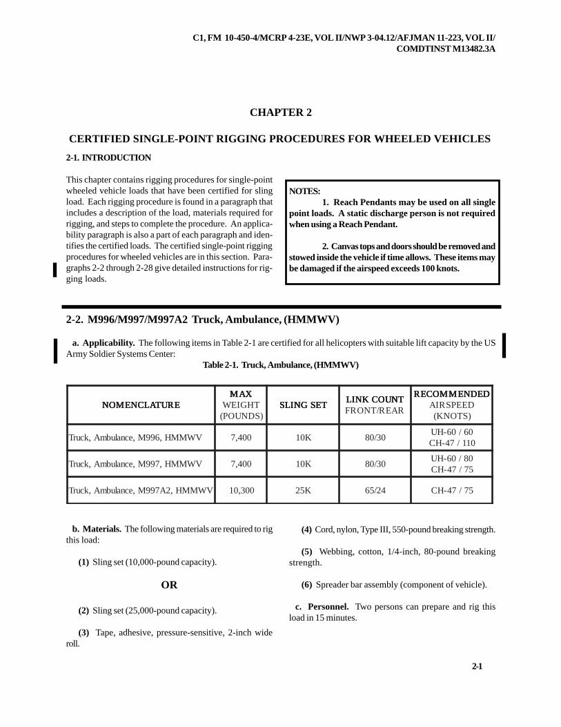
b. Materials. The following materials are required to rigthis load:
(1) Sling set (10,000-pound capacity).
OR
(2) Sling set (25,000-pound capacity).
(3) Tape, adhesive, pressure-sensitive, 2-inch wideroll.
(4) Cord, nylon, Type III, 550-pound breaking strength.
(5) Webbing, cotton, 1/4-inch, 80-pound breakingstrength.
(6) Spreader bar assembly (component of vehicle).
c. Personnel. Two persons can prepare and rig thisload in 15 minutes.
2-2. M996/M997/M997A2 Truck, Ambulance, (HMMWV)
a. Applicability. The following items in Table 2-1 are certified for all helicopters with suitable lift capacity by the USArmy Soldier Systems Center:
Table 2-1. Truck, Ambulance, (HMMWV)
NOTES:1. Reach Pendants may be used on all single
point loads. A static discharge person is not requiredwhen using a Reach Pendant.
2. Canvas tops and doors should be removed andstowed inside the vehicle if time allows. These items maybe damaged if the airspeed exceeds 100 knots.
ERUTALCNEMON ERUTALCNEMON ERUTALCNEMON ERUTALCNEMON ERUTALCNEMONXAM XAM XAM XAM XAM
THGIEW)SDNUOP(
TESGNILS TESGNILS TESGNILS TESGNILS TESGNILSTNUOCKNIL TNUOCKNIL TNUOCKNIL TNUOCKNIL TNUOCKNILRAER/TNORF
DEDNEMMOCER DEDNEMMOCER DEDNEMMOCER DEDNEMMOCER DEDNEMMOCERDEEPSRIA)STONK(
VWMMH,699M,ecnalubmA,kcurT 004,7 K01 03/0806/06-HU011/74-HC
VWMMH,799M,ecnalubmA,kcurT 004,7 K01 03/0808/06-HU57/74-HC
VWMMH,2A799M,ecnalubmA,kcurT 003,01 K52 42/56 57/74-HC
2-2
C1, FM 10-450-4/MCRP 4-23E, VOL II/NWP 3-04.12/AFJMAN 11-223, VOL II/COMDTINST M13482.3A
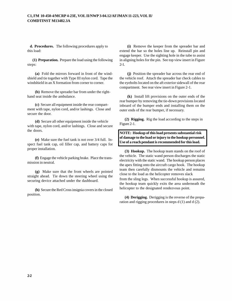
d. Procedures. The following procedures apply tothis load:
(1) Preparation. Prepare the load using the followingsteps:
(a) Fold the mirrors forward in front of the wind-shield and tie together with Type III nylon cord. Tape thewindshield in an X formation from corner to corner.
(b) Remove the spreader bar from under the right-hand seat inside the ambulance.
(c) Secure all equipment inside the rear compart-ment with tape, nylon cord, and/or lashings. Close andsecure the door.
(d) Secure all other equipment inside the vehiclewith tape, nylon cord, and/or lashings. Close and securethe doors.
(e) Make sure the fuel tank is not over 3/4 full. In-spect fuel tank cap, oil filler cap, and battery caps forproper installation.
(f) Engage the vehicle parking brake. Place the trans-mission in neutral.
(g) Make sure that the front wheels are pointedstraight ahead. Tie down the steering wheel using thesecuring device attached under the dashboard.
(h) Secure the Red Cross insignia covers in the closedposition.
(i) Remove the keeper from the spreader bar andextend the bar so the holes line up. Reinstall pin andengage keeper. Use the sighting hole in the tube to assistin aligning holes for the pin. See top view insert in Figure2-1.
(j) Position the spreader bar across the rear end ofthe vehicle roof. Attach the spreader bar check cables tothe eyebolts located on the aft exterior sidewall of the rearcompartment. See rear view insert in Figure 2-1.
(k) Install lift provisions on the outer ends of therear bumper by removing the tie-down provisions locatedinboard of the bumper ends and installing them on theouter ends of the rear bumper, if necessary.
(2) Rigging. Rig the load according to the steps inFigure 2-1.
NOTE: Hookup of this load presents substantial riskof damage to the load or injury to the hookup personnel.Use of a reach pendant is recommended for this load.
(3) Hookup. The hookup team stands on the roof ofthe vehicle. The static wand person discharges the staticelectricity with the static wand. The hookup person placesthe apex fitting onto the aircraft cargo hook. The hookupteam then carefully dismounts the vehicle and remainsclose to the load as the helicopter removes slackfrom the sling legs. When successful hookup is assured,the hookup team quickly exits the area underneath thehelicopter to the designated rendezvous point.
(4) Derigging. Derigging is the reverse of the prepa-ration and rigging procedures in steps d (1) and d (2).
C1, FM 10-450-4/MCRP 4-23E, VOL II/NWP 3-04.12/AFJMAN 11-223, VOL II/COMDTINST M13482.3A
2-21
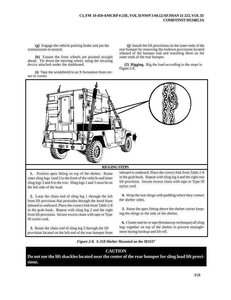
inboard to outboard. Place the correct link from Table 2-8in the grab hook. Repeat with sling leg 4 and the right rearlift provision. Secure excess chain with tape or Type IIInylon cord.
4. Wrap the rear slings with padding where they contactthe shelter sides.
5. Raise the apex fitting above the shelter carrier keep-ing the slings to the side of the shelter.
6. Cluster and tie or tape (breakaway technique) all slinglegs together on top of the shelter to prevent entangle-ment during hookup and lift-off.
Figure 2-8. S-318 Shelter Mounted on the M1037
CAUTIONDo not use the lift shackles located near the center of the rear bumper for sling load lift provi-sions.
1. Position apex fitting on top of the shelter. Routeouter sling legs 1and 2 to the front of the vehicle and innersling legs 3 and 4 to the rear. Sling legs 1 and 3 must be onthe left side of the load.
2. Loop the chain end of sling leg 1 through the leftfront lift provision that protrudes through the hood frominboard to outboard. Place the correct link from Table 2-8in the grab hook. Repeat with sling leg 2 and the rightfront lift provision. Secure excess chain with tape or TypeIII nylon cord.
3. Route the chain end of sling leg 3 through the liftprovision located on the left end of the rear bumper from
RIGGING STEPS
(g) Engage the vehicle parking brake and put thetransmission in neutral.
(h) Ensure the front wheels are pointed straightahead. Tie down the steering wheel, using the securingdevice attached under the dashboard.
(i) Tape the windshield in an X formation from cor-ner to corner.
(j) Install the lift provisions on the outer ends of therear bumper by removing the tiedown provisions locatedinboard of the bumper end and installing them on theouter ends of the rear bumper.
(2) Rigging. Rig the load according to the steps inFigure 2-8.

2-22
C1, FM 10-450-4/MCRP 4-23E, VOL II/NWP 3-04.12/AFJMAN 11-223, VOL II/COMDTINST M13482.3A
NOTE: Hookup of this load presents substantial riskof damage to the load or injury to the hookup personnel.Use of a reach pendant is recommended for this load.
(3) Hookup. The hookup team stands on top of theshelter. The static wand person discharges the static elec-tricity with the static wand. The hookup person places
the apex fitting onto the aircraft cargo hook. The hookupteam then carefully dismounts the vehicle and remainsclose to the load as the helicopter removes slack from thesling legs. When successful hookup is assured, thehookup team quickly exits the area underneath the heli-copter to the designated rendezvous point.
(4) Derigging. Derigging is the reverse of the prepara-tion and rigging procedures in steps d (1) and d (2).
2-10. M1097/M1097A2 Shelter Carrier (HMMWV) With Lightweight MultipurposeShelter (LMS)
a. Applicability. The following items in Table 2-9 are certified for all helicopters with suitable lift capacity by the USArmy Soldier Systems Center:
Table 2-9. Lightweight Multipurpose Shelter (LMS)
TNAIRAVRETLEHS TNAIRAVRETLEHS TNAIRAVRETLEHS TNAIRAVRETLEHS TNAIRAVRETLEHSERUTALCNEMON
XAM XAM XAM XAM XAMTHGIEW
)SDNUOP(TESGNILS TESGNILS TESGNILS TESGNILS TESGNILS
TNUOCKNIL TNUOCKNIL TNUOCKNIL TNUOCKNIL TNUOCKNILRAER/TNORF
DEDNEMMOCER DEDNEMMOCER DEDNEMMOCER DEDNEMMOCER DEDNEMMOCERDEEPSRIA)STONK(
)DMH(dezisnwoDytiliboMhgiHlartneCtroppuSriAtceriD
024,8 K51 3/04 021
puorG)CO(lartneCsnoitarepO8)V(63-QPT/NAredniferiF
026,8 K01 3/05 021
metsySnoitceteDdetargetnIlacigoloiB)SDIB(
000,9 K01 3/04 011
smetsySlacigoloroeteMdetargetnIII&IkcolB,)STEMI(
050,9 K01 3/07 021
gnitropeRnoitacoLnoitisoPdecnahnEteNdezisnwoD)SRLPE(metsyS
)D(E-SCN(noitatSlortnoC000,01 K01 3/07 021
)MGD(rexelpitluMpuorGlatigiDC831-CRT/NA
020,9 K01 01/06 511
rexelpitluMpuorGlatigiDytiliboMhgiH,B371-CRT/NA)ADMH(egalbmessA
B571-CRT/NA,B471-CRT/NA001,9 K01 01/06 001
lartneCsnoitacinummoCycneuqerFhgiH021CRT/NA
567,8 K51 5/05 021
ecnegilletnIecroFyranoitidepxEeniraM)SAI(metsySsisylanA
022,9 K51 2/46 021
C1, FM 10-450-4/MCRP 4-23E, VOL II/NWP 3-04.12/AFJMAN 11-223, VOL II/COMDTINST M13482.3A
2-23
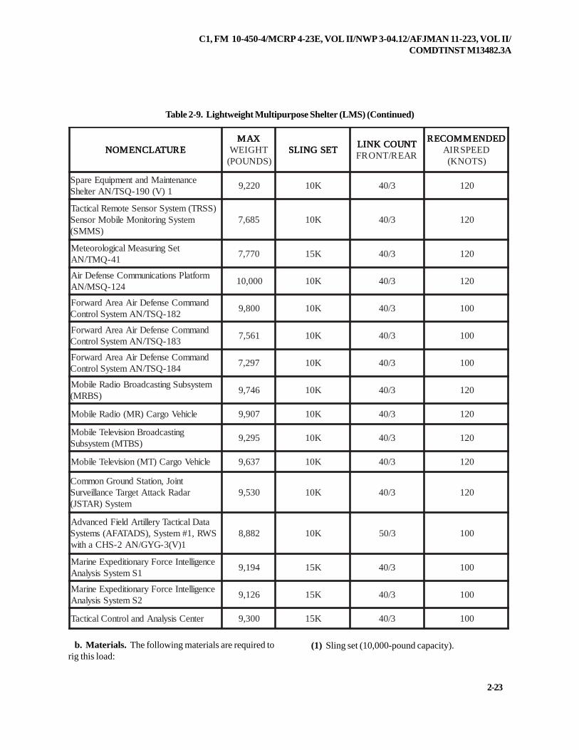
Table 2-9. Lightweight Multipurpose Shelter (LMS) (Continued)
ERUTALCNEMON ERUTALCNEMON ERUTALCNEMON ERUTALCNEMON ERUTALCNEMONXAM XAM XAM XAM XAM
THGIEW)SDNUOP(
TESGNILS TESGNILS TESGNILS TESGNILS TESGNILSTNUOCKNIL TNUOCKNIL TNUOCKNIL TNUOCKNIL TNUOCKNILRAER/TNORF
DEDNEMMOCER DEDNEMMOCER DEDNEMMOCER DEDNEMMOCER DEDNEMMOCERDEEPSRIA)STONK(
ecnanetniaMdnatnempiuqEerapS1)V(091-QST/NAretlehS
022,9 K01 3/04 021
)SSRT(metsySrosneSetomeRlacitcaTmetsySgnirotinoMeliboMrosneS
)SMMS(586,7 K01 3/04 021
teSgnirusaeMlacigoloroeteM14-QMT/NA
077,7 K51 3/04 021
mroftalPsnoitacinummoCesnefeDriA421-QSM/NA
000,01 K01 3/04 021
dnammoCesnefeDriAaerAdrawroF281-QST/NAmetsySlortnoC
008,9 K01 3/04 001
dnammoCesnefeDriAaerAdrawroF381-QST/NAmetsySlortnoC
165,7 K01 3/04 001
dnammoCesnefeDriAaerAdrawroF481-QST/NAmetsySlortnoC
792,7 K01 3/04 001
metsysbuSgnitsacdaorBoidaReliboM)SBRM(
647,9 K01 3/04 021
elciheVograC)RM(oidaReliboM 709,9 K01 3/04 021
gnitsacdaorBnoisiveleTeliboM)SBTM(metsysbuS
592,9 K01 3/04 021
elciheVograC)TM(noisiveleTeliboM 736,9 K01 3/04 021
tnioJ,noitatSdnuorGnommoCradaRkcattAtegraTecnallievruS
metsyS)RATSJ(035,9 K01 3/04 021
ataDlacitcaTyrellitrAdleiFdecnavdASWR,1#metsyS,)SDATAFA(smetsyS
1)V(3-GYG/NA2-SHCahtiw288,8 K01 3/05 001
ecnegilletnIecroFyranoitidepxEeniraM1SmetsySsisylanA
491,9 K51 3/04 001
ecnegilletnIecroFyranoitidepxEeniraM2SmetsySsisylanA
621,9 K51 3/04 001
retneCsisylanAdnalortnoClacitcaT 003,9 K51 3/04 001
b. Materials. The following materials are required torig this load:
(1) Sling set (10,000-pound capacity).
2-24
C1, FM 10-450-4/MCRP 4-23E, VOL II/NWP 3-04.12/AFJMAN 11-223, VOL II/COMDTINST M13482.3A
(a) Chain length, part number 38850-00053-101,from a 10,000-pound capacity sling set (4 each).
(b) Coupling link, part number 577-0615, from a10,000-pound sling set (4 each).
OR(2) Multileg sling set (15,000-pound capacity for the
CH-53E only).
(a) Additional chain lengths from 15,000-poundcapacity sling sets (8 each).
(b) Additional coupling links from 15,000-poundcapacity sling sets (8 each).
(3) Tape, adhesive, pressure-sensitive, 2-inch wideroll.
(4) Cord, nylon, Type III, 550-pound breaking strength.
(5) Webbing, cotton, 1/4-inch, 80-pound breakingstrength.
(6) Felt sheet, cattle hair, Type IV, 1/2-inch or suitablepadding.
c. Personnel. Two persons can prepare and rig thisload in 15 minutes.
d. Procedures. The following procedures apply tothis load:
(1) Preparation. Prepare the load using the followingsteps:
(a) Extend the sling leg chains by connecting oneadditional chain length to each chain on a 10,000-, 25,000-or 40,000-pound capacity sling set with coupling links.Connect two additional chain lengths to each chain onthe 15,000-pound multileg sling set chain with couplinglinks.
(b) Fold mirrors forward in front of the windshield foradded protection and tie together with Type III nylon cord.
(c) Secure the shelter to the truck using wire ropeor tie-down assemblies.
(d) Secure all equipment inside the shelter with tape,
nylon cord, or lashings; close and secure shelter ventsand door with nylon cord or tape.
(e) Secure environmental control unit cover withtape.
(f) Disconnect the power cord from the rear paneland secure it to the rear platform with Type III nylon cord.Lower the power panel door and secure the door.
(g) Secure all equipment and cargo inside thevehicle with tape, nylon cord, or lashings. Secure thedoors shut if installed.
(h) Ensure the fuel tank is not over 3/4 full. Inspectfuel tank cap, oil filler cap, and battery caps for properinstallation.
(i) Engage the vehicle parking brake and put thetransmission in neutral.
(j) Ensure the front wheels are pointed straight ahead.Tie down the steering wheel, using the securing deviceattached under the dashboard.
(k) Tape the windshield in an X formation from cor-ner to corner.
(l) Install the lift provisions on the outer ends of therear bumper by removing the tiedown provisions locatedinboard of the bumper end and installing them on theouter ends of the rear bumper.
(m) Remove the upper antenna mounting bracket ifinstalled.
(2) Rigging. Rig the load according to the steps inFigure 2-9.
NOTE: Hookup of this load presents substantial risk ofdamage to the load or injury to the hookup personnel.Use of a reach pendant is recommended for this load.
(3) Hookup. The hookup team stands on top of theshelter. The static wand person discharges the static elec-tricity with the static wand. The hookup person placesthe apex fitting onto the aircraft cargo hook. The hookupteam then carefully dismounts the vehicle and remainsclose to the load as the helicopter removes slack from the
C1, FM 10-450-4/MCRP 4-23E, VOL II/NWP 3-04.12/AFJMAN 11-223, VOL II/COMDTINST M13482.3A
2-25
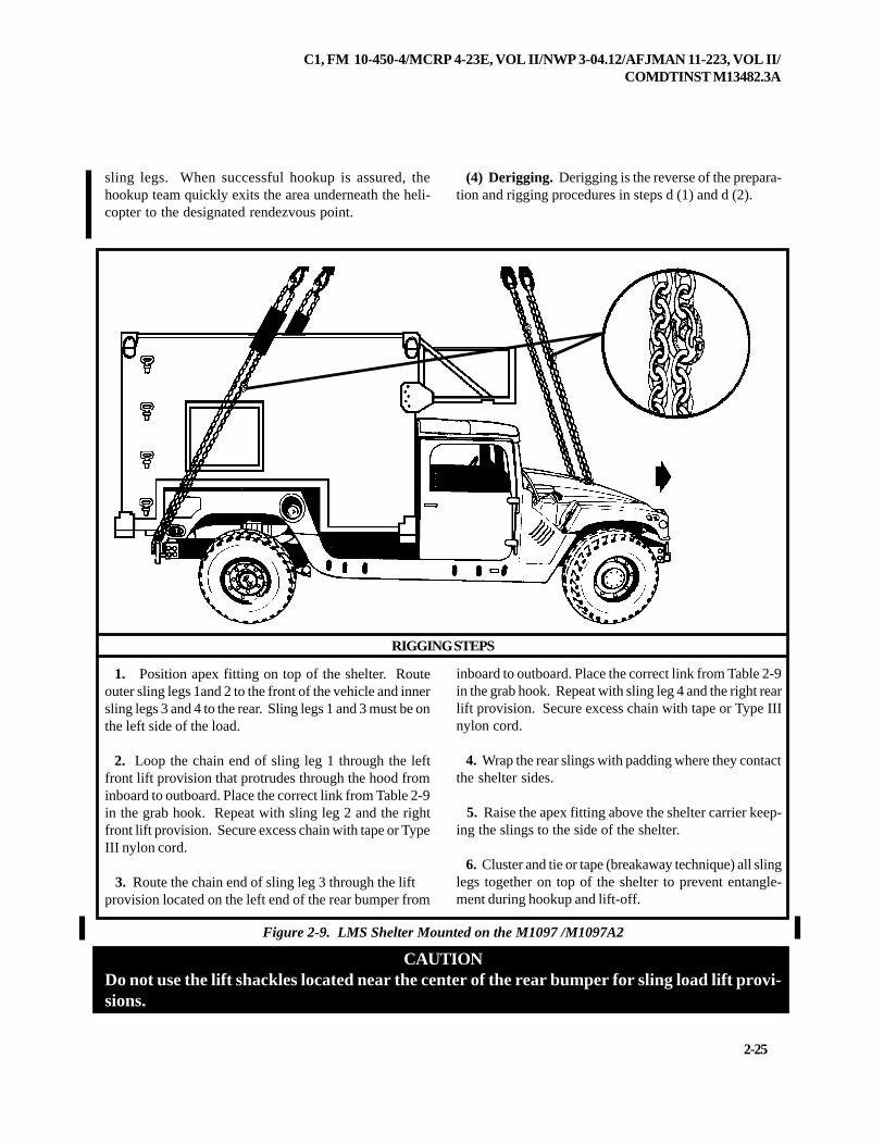
CAUTIONDo not use the lift shackles located near the center of the rear bumper for sling load lift provi-sions.
Figure 2-9. LMS Shelter Mounted on the M1097 /M1097A2
RIGGING STEPS
1. Position apex fitting on top of the shelter. Routeouter sling legs 1and 2 to the front of the vehicle and innersling legs 3 and 4 to the rear. Sling legs 1 and 3 must be onthe left side of the load.
2. Loop the chain end of sling leg 1 through the leftfront lift provision that protrudes through the hood frominboard to outboard. Place the correct link from Table 2-9in the grab hook. Repeat with sling leg 2 and the rightfront lift provision. Secure excess chain with tape or TypeIII nylon cord.
3. Route the chain end of sling leg 3 through the liftprovision located on the left end of the rear bumper from
inboard to outboard. Place the correct link from Table 2-9in the grab hook. Repeat with sling leg 4 and the right rearlift provision. Secure excess chain with tape or Type IIInylon cord.
4. Wrap the rear slings with padding where they contactthe shelter sides.
5. Raise the apex fitting above the shelter carrier keep-ing the slings to the side of the shelter.
6. Cluster and tie or tape (breakaway technique) all slinglegs together on top of the shelter to prevent entangle-ment during hookup and lift-off.
sling legs. When successful hookup is assured, thehookup team quickly exits the area underneath the heli-copter to the designated rendezvous point.
(4) Derigging. Derigging is the reverse of the prepara-tion and rigging procedures in steps d (1) and d (2).
2-26
C1, FM 10-450-4/MCRP 4-23E, VOL II/NWP 3-04.12/AFJMAN 11-223, VOL II/COMDTINST M13482.3A
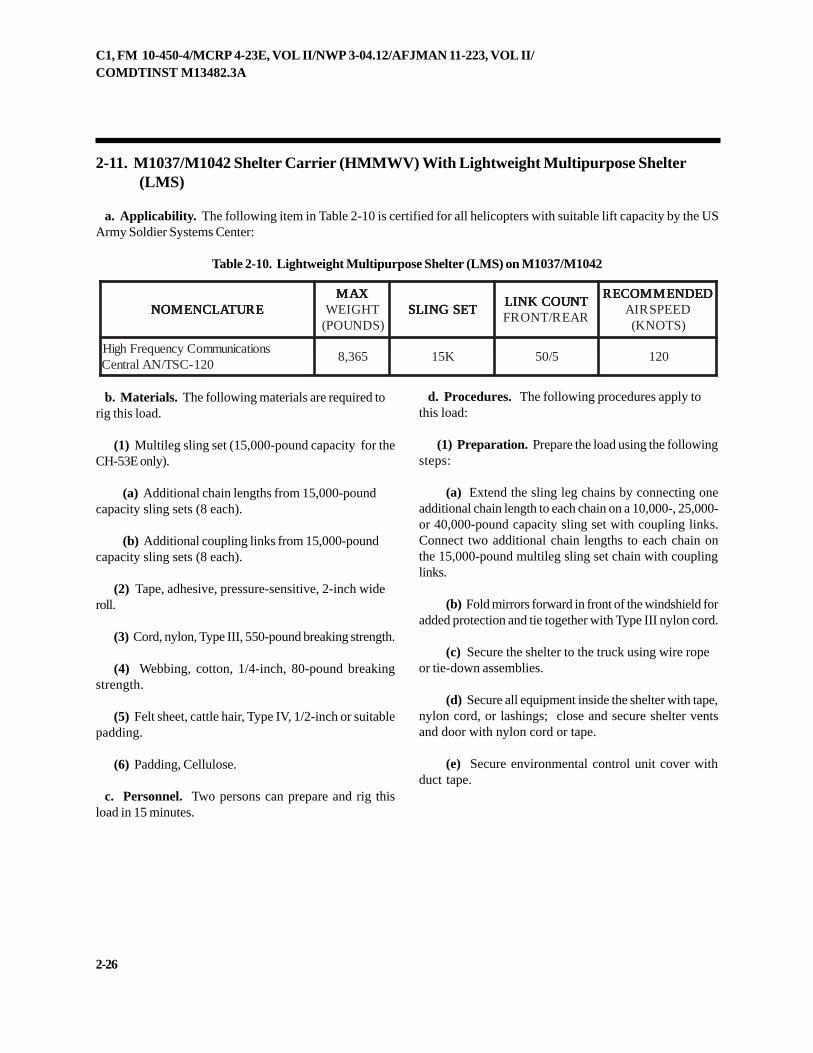
2-11. M1037/M1042 Shelter Carrier (HMMWV) With Lightweight Multipurpose Shelter (LMS)
a. Applicability. The following item in Table 2-10 is certified for all helicopters with suitable lift capacity by the USArmy Soldier Systems Center:
Table 2-10. Lightweight Multipurpose Shelter (LMS) on M1037/M1042
ERUTALCNEMON ERUTALCNEMON ERUTALCNEMON ERUTALCNEMON ERUTALCNEMONXAM XAM XAM XAM XAM
THGIEW)SDNUOP(
TESGNILS TESGNILS TESGNILS TESGNILS TESGNILSTNUOCKNIL TNUOCKNIL TNUOCKNIL TNUOCKNIL TNUOCKNILRAER/TNORF
DEDNEMMOCER DEDNEMMOCER DEDNEMMOCER DEDNEMMOCER DEDNEMMOCERDEEPSRIA)STONK(
snoitacinummoCycneuqerFhgiH021-CST/NAlartneC
563,8 K51 5/05 021
b. Materials. The following materials are required torig this load.
(1) Multileg sling set (15,000-pound capacity for theCH-53E only).
(a) Additional chain lengths from 15,000-poundcapacity sling sets (8 each).
(b) Additional coupling links from 15,000-poundcapacity sling sets (8 each).
(2) Tape, adhesive, pressure-sensitive, 2-inch wideroll.
(3) Cord, nylon, Type III, 550-pound breaking strength.
(4) Webbing, cotton, 1/4-inch, 80-pound breakingstrength.
(5) Felt sheet, cattle hair, Type IV, 1/2-inch or suitablepadding.
(6) Padding, Cellulose.
c. Personnel. Two persons can prepare and rig thisload in 15 minutes.
d. Procedures. The following procedures apply tothis load:
(1) Preparation. Prepare the load using the followingsteps:
(a) Extend the sling leg chains by connecting oneadditional chain length to each chain on a 10,000-, 25,000-or 40,000-pound capacity sling set with coupling links.Connect two additional chain lengths to each chain onthe 15,000-pound multileg sling set chain with couplinglinks.
(b) Fold mirrors forward in front of the windshield foradded protection and tie together with Type III nylon cord.
(c) Secure the shelter to the truck using wire ropeor tie-down assemblies.
(d) Secure all equipment inside the shelter with tape,nylon cord, or lashings; close and secure shelter ventsand door with nylon cord or tape.
(e) Secure environmental control unit cover withduct tape.
C1, FM 10-450-4/MCRP 4-23E, VOL II/NWP 3-04.12/AFJMAN 11-223, VOL II/COMDTINST M13482.3A
2-47
RIGGING STEPS
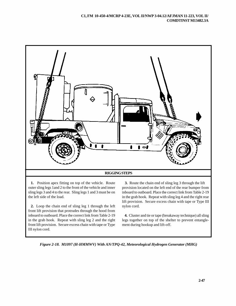
1. Position apex fitting on top of the vehicle. Routeouter sling legs 1and 2 to the front of the vehicle and innersling legs 3 and 4 to the rear. Sling legs 1 and 3 must be onthe left side of the load.
2. Loop the chain end of sling leg 1 through the leftfront lift provision that protrudes through the hood frominboard to outboard. Place the correct link from Table 2-19in the grab hook. Repeat with sling leg 2 and the rightfront lift provision. Secure excess chain with tape or TypeIII nylon cord.
3. Route the chain end of sling leg 3 through the liftprovision located on the left end of the rear bumper frominboard to outboard. Place the correct link from Table 2-19in the grab hook. Repeat with sling leg 4 and the right rearlift provision. Secure excess chain with tape or Type IIInylon cord.
4. Cluster and tie or tape (breakaway technique) all slinglegs together on top of the shelter to prevent entangle-ment during hookup and lift-off.
Figure 2-18. M1097 (H-HMMWV) With AN/TPQ-42, Meteorological Hydrogen Generator (MHG)
2-48
C1, FM 10-450-4/MCRP 4-23E, VOL II/NWP 3-04.12/AFJMAN 11-223, VOL II/COMDTINST M13482.3A
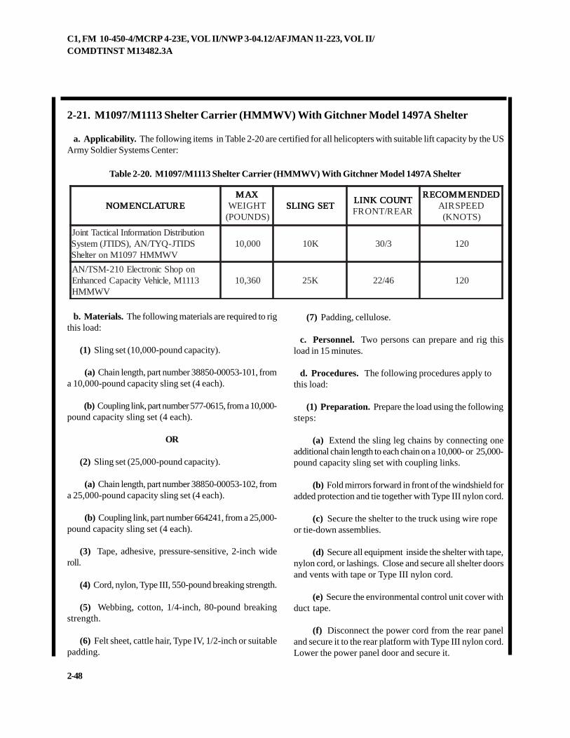
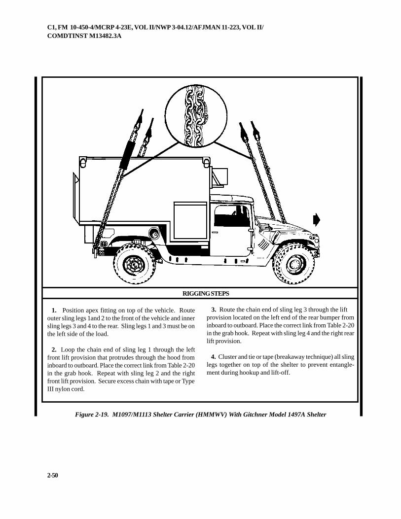
2-21. M1097/M1113 Shelter Carrier (HMMWV) With Gitchner Model 1497A Shelter
a. Applicability. The following items in Table 2-20 are certified for all helicopters with suitable lift capacity by the USArmy Soldier Systems Center:
Table 2-20. M1097/M1113 Shelter Carrier (HMMWV) With Gitchner Model 1497A Shelter
b. Materials. The following materials are required to rigthis load:
(1) Sling set (10,000-pound capacity).
(a) Chain length, part number 38850-00053-101, froma 10,000-pound capacity sling set (4 each).
(b) Coupling link, part number 577-0615, from a 10,000-pound capacity sling set (4 each).
OR
(2) Sling set (25,000-pound capacity).
(a) Chain length, part number 38850-00053-102, froma 25,000-pound capacity sling set (4 each).
(b) Coupling link, part number 664241, from a 25,000-pound capacity sling set (4 each).
(3) Tape, adhesive, pressure-sensitive, 2-inch wideroll.
(4) Cord, nylon, Type III, 550-pound breaking strength.
(5) Webbing, cotton, 1/4-inch, 80-pound breakingstrength.
(6) Felt sheet, cattle hair, Type IV, 1/2-inch or suitablepadding.
(7) Padding, cellulose.
c. Personnel. Two persons can prepare and rig thisload in 15 minutes.
d. Procedures. The following procedures apply tothis load:
(1) Preparation. Prepare the load using the followingsteps:
(a) Extend the sling leg chains by connecting oneadditional chain length to each chain on a 10,000- or 25,000-pound capacity sling set with coupling links.
(b) Fold mirrors forward in front of the windshield foradded protection and tie together with Type III nylon cord.
(c) Secure the shelter to the truck using wire ropeor tie-down assemblies.
(d) Secure all equipment inside the shelter with tape,nylon cord, or lashings. Close and secure all shelter doorsand vents with tape or Type III nylon cord.
(e) Secure the environmental control unit cover withduct tape.
(f) Disconnect the power cord from the rear paneland secure it to the rear platform with Type III nylon cord.Lower the power panel door and secure it.
ERUTALCNEMON ERUTALCNEMON ERUTALCNEMON ERUTALCNEMON ERUTALCNEMONXAM XAM XAM XAM XAM
THGIEW)SDNUOP(
TESGNILS TESGNILS TESGNILS TESGNILS TESGNILSTNUOCKNIL TNUOCKNIL TNUOCKNIL TNUOCKNIL TNUOCKNILRAER/TNORF
DEDNEMMOCER DEDNEMMOCER DEDNEMMOCER DEDNEMMOCER DEDNEMMOCERDEEPSRIA)STONK(
noitubirtsiDnoitamrofnIlacitcaTtnioJSDITJ-QYT/NA,)SDITJ(metsyS
VWMMH7901MnoretlehS000,01 K01 3/03 021
nopohScinortcelE012-MST/NA3111M,elciheVyticapaCdecnahnE
VWMMH063,01 K52 64/22 021
C1, FM 10-450-4/MCRP 4-23E, VOL II/NWP 3-04.12/AFJMAN 11-223, VOL II/COMDTINST M13482.3A
2-49
(g) Secure all equipment and cargo inside thevehicle with tape, nylon cord, or lashings. Secure thedoors shut if installed.
(h) Ensure the fuel tank is not over 3/4 full. Inspectfuel tank cap, oil filler cap, and battery caps for properinstallation.
(i) Engage the vehicle parking brake and put thetransmission in neutral.
(j) Ensure the front wheels are pointed straight ahead.Tie down the steering wheel, using the securing deviceattached under the dashboard.
(k) Tape the windshield in an X formation from cor-ner to corner.
(l) Install the lift provisions on the outer ends of therear bumper by removing the tiedown provisions locatedinboard of the bumper end and installing them on the
outer ends of the rear bumper.
(2) Rigging. Rig the load according to the steps inFigure 2-19.
NOTE: Hookup of this load presents substantial riskof damage to the load or injury to the hookup personnel.Use of a reach pendant is recommended for this load.
(3) Hookup. The hookup team stands on top of theshelter. The static wand person discharges the static elec-tricity with the static wand. The hookup person placesthe apex fitting onto the aircraft cargo hook. The hookupteam then carefully dismounts the vehicle and remainsclose to the load as the helicopter removes slack from thesling legs. When successful hookup is assured, thehookup team quickly exits the area underneath the heli-copter to the designated rendezvous point.
(4) Derigging. Derigging is the reverse of the prepara-tion and rigging procedures in steps d (1) and d (2).
2-50
C1, FM 10-450-4/MCRP 4-23E, VOL II/NWP 3-04.12/AFJMAN 11-223, VOL II/COMDTINST M13482.3A
RIGGING STEPS
1. Position apex fitting on top of the vehicle. Routeouter sling legs 1and 2 to the front of the vehicle and innersling legs 3 and 4 to the rear. Sling legs 1 and 3 must be onthe left side of the load.
2. Loop the chain end of sling leg 1 through the leftfront lift provision that protrudes through the hood frominboard to outboard. Place the correct link from Table 2-20in the grab hook. Repeat with sling leg 2 and the rightfront lift provision. Secure excess chain with tape or TypeIII nylon cord.
3. Route the chain end of sling leg 3 through the liftprovision located on the left end of the rear bumper frominboard to outboard. Place the correct link from Table 2-20in the grab hook. Repeat with sling leg 4 and the right rearlift provision.
4. Cluster and tie or tape (breakaway technique) all slinglegs together on top of the shelter to prevent entangle-ment during hookup and lift-off.
Figure 2-19. M1097/M1113 Shelter Carrier (HMMWV) With Gitchner Model 1497A Shelter
C1, FM 10-450-4/MCRP 4-23E, VOL II/NWP 3-04.12/AFJMAN 11-223, VOL II/COMDTINST M13482.3A
2-51
2-22. M1097 (HMMWV) With Contact Maintenance Truck, Heavy (CMTH)
a. Applicability. The following item in Table 2-21 is certified for all helicopters with suitable lift capacity by the USArmy Soldier Systems Center:
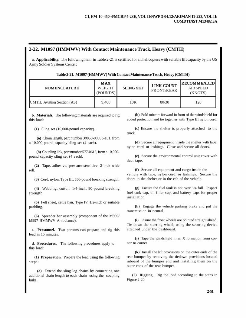
Table 2-21. M1097 (HMMWV) With Contact Maintenance Truck, Heavy (CMTH)
b. Materials. The following materials are required to rigthis load:
(1) Sling set (10,000-pound capacity).
(a) Chain length, part number 38850-00053-101, froma 10,000-pound capacity sling set (4 each).
(b) Coupling link, part number 577-0615, from a 10,000-pound capacity sling set (4 each).
(2) Tape, adhesive, pressure-sensitive, 2-inch wideroll.
(3) Cord, nylon, Type III, 550-pound breaking strength.
(4) Webbing, cotton, 1/4-inch, 80-pound breakingstrength.
(5) Felt sheet, cattle hair, Type IV, 1/2-inch or suitablepadding.
(6) Spreader bar assembly (component of the M996/M997 HMMWV Ambulance).
c. Personnel. Two persons can prepare and rig thisload in 15 minutes.
d. Procedures. The following procedures apply tothis load:
(1) Preparation. Prepare the load using the followingsteps:
(a) Extend the sling leg chains by connecting oneadditional chain length to each chain using the couplinglinks.
(b) Fold mirrors forward in front of the windshield foradded protection and tie together with Type III nylon cord.
(c) Ensure the shelter is properly attached to thetruck.
(d) Secure all equipment inside the shelter with tape,nylon cord, or lashings. Close and secure all doors.
(e) Secure the environmental control unit cover withduct tape.
(f) Secure all equipment and cargo inside thevehicle with tape, nylon cord, or lashings. Secure thedoors in the shelter or in the cab of the vehicle.
(g) Ensure the fuel tank is not over 3/4 full. Inspectfuel tank cap, oil filler cap, and battery caps for properinstallation.
(h) Engage the vehicle parking brake and put thetransmission in neutral.
(i) Ensure the front wheels are pointed straight ahead.Tie down the steering wheel, using the securing deviceattached under the dashboard.
(j) Tape the windshield in an X formation from cor-ner to corner.
(k) Install the lift provisions on the outer ends of therear bumper by removing the tiedown provisions locatedinboard of the bumper end and installing them on theouter ends of the rear bumper.
(2) Rigging. Rig the load according to the steps inFigure 2-20.
ERUTALCNEMON ERUTALCNEMON ERUTALCNEMON ERUTALCNEMON ERUTALCNEMONXAM XAM XAM XAM XAM
THGIEW)SDNUOP(
TESGNILS TESGNILS TESGNILS TESGNILS TESGNILSTNUOCKNIL TNUOCKNIL TNUOCKNIL TNUOCKNIL TNUOCKNILRAER/TNORF
DEDNEMMOCER DEDNEMMOCER DEDNEMMOCER DEDNEMMOCER DEDNEMMOCERDEEPSRIA)STONK(
)SA(noitceSnoitaivA,HTMC 004,9 K01 03/08 021
2-52
C1, FM 10-450-4/MCRP 4-23E, VOL II/NWP 3-04.12/AFJMAN 11-223, VOL II/COMDTINST M13482.3A
RIGGING STEPS
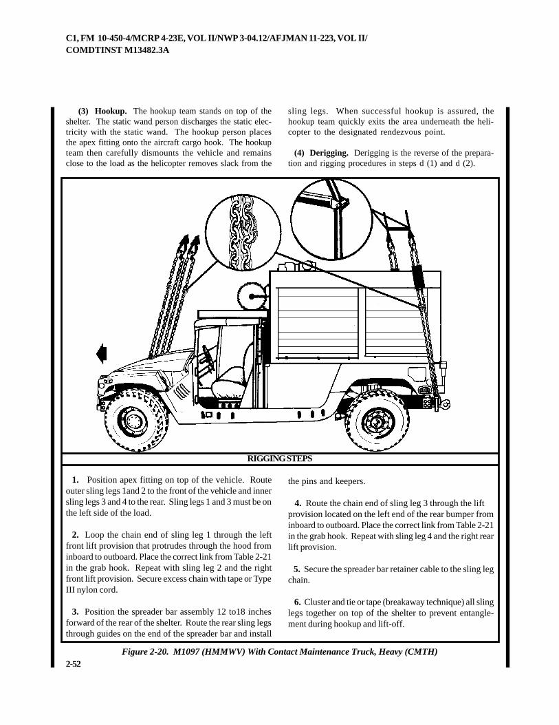
Figure 2-20. M1097 (HMMWV) With Contact Maintenance Truck, Heavy (CMTH)
1. Position apex fitting on top of the vehicle. Routeouter sling legs 1and 2 to the front of the vehicle and innersling legs 3 and 4 to the rear. Sling legs 1 and 3 must be onthe left side of the load.
2. Loop the chain end of sling leg 1 through the leftfront lift provision that protrudes through the hood frominboard to outboard. Place the correct link from Table 2-21in the grab hook. Repeat with sling leg 2 and the rightfront lift provision. Secure excess chain with tape or TypeIII nylon cord.
3. Position the spreader bar assembly 12 to18 inchesforward of the rear of the shelter. Route the rear sling legsthrough guides on the end of the spreader bar and install
the pins and keepers.
4. Route the chain end of sling leg 3 through the liftprovision located on the left end of the rear bumper frominboard to outboard. Place the correct link from Table 2-21in the grab hook. Repeat with sling leg 4 and the right rearlift provision.
5. Secure the spreader bar retainer cable to the sling legchain.
6. Cluster and tie or tape (breakaway technique) all slinglegs together on top of the shelter to prevent entangle-ment during hookup and lift-off.
(3) Hookup. The hookup team stands on top of theshelter. The static wand person discharges the static elec-tricity with the static wand. The hookup person placesthe apex fitting onto the aircraft cargo hook. The hookupteam then carefully dismounts the vehicle and remainsclose to the load as the helicopter removes slack from the
sling legs. When successful hookup is assured, thehookup team quickly exits the area underneath the heli-copter to the designated rendezvous point.
(4) Derigging. Derigging is the reverse of the prepara-tion and rigging procedures in steps d (1) and d (2).
C1, FM 10-450-4/MCRP 4-23E, VOL II/NWP 3-04.12/AFJMAN 11-223, VOL II/COMDTINST M13482.3A
2-53
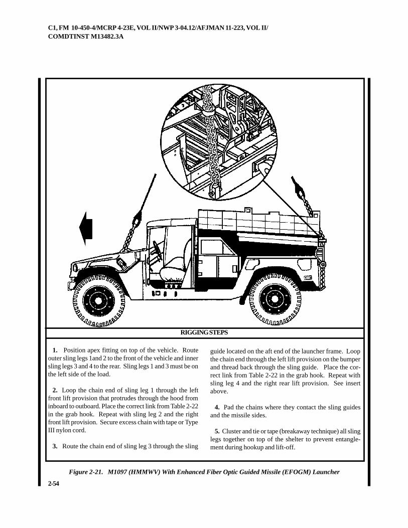
2-23. M1097 (HMMWV) With Enhanced Fiber Optic Guided Missile (EFOGM) Launcher
a. Applicability. The following item in Table 2-22 is certified for all helicopters with suitable lift capacity by the USArmy Soldier Systems Center:
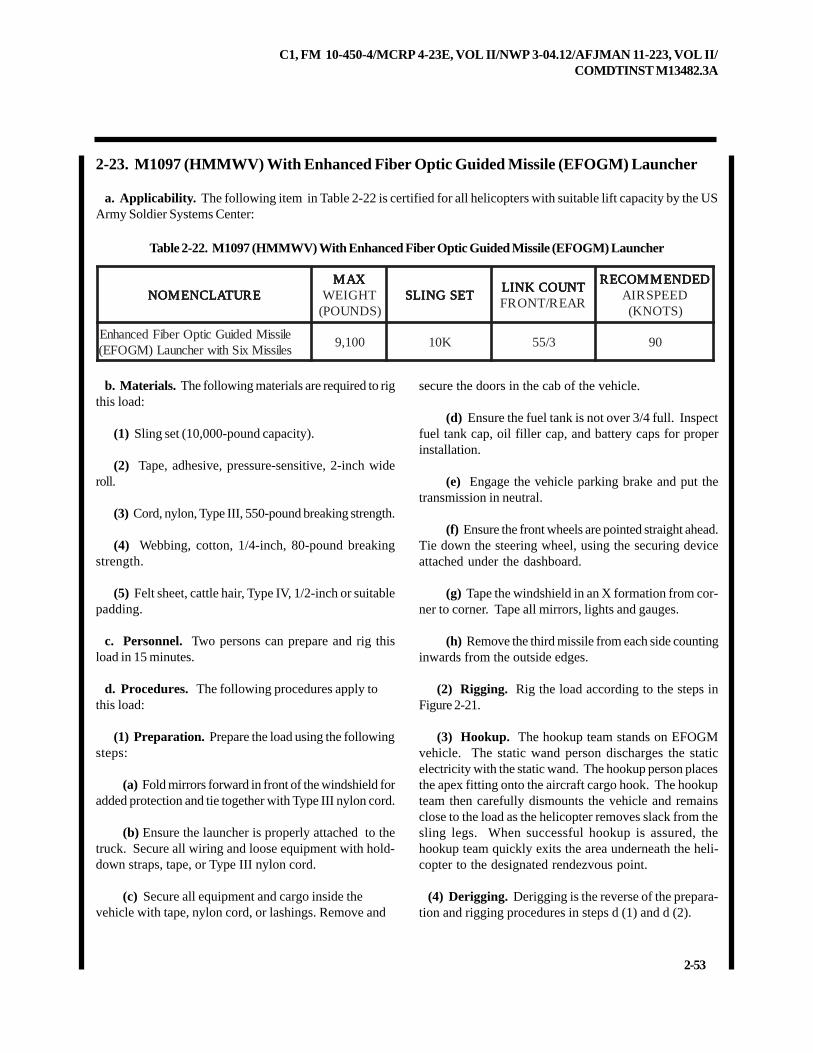
Table 2-22. M1097 (HMMWV) With Enhanced Fiber Optic Guided Missile (EFOGM) Launcher
b. Materials. The following materials are required to rigthis load:
(1) Sling set (10,000-pound capacity).
(2) Tape, adhesive, pressure-sensitive, 2-inch wideroll.
(3) Cord, nylon, Type III, 550-pound breaking strength.
(4) Webbing, cotton, 1/4-inch, 80-pound breakingstrength.
(5) Felt sheet, cattle hair, Type IV, 1/2-inch or suitablepadding.
c. Personnel. Two persons can prepare and rig thisload in 15 minutes.
d. Procedures. The following procedures apply tothis load:
(1) Preparation. Prepare the load using the followingsteps:
(a) Fold mirrors forward in front of the windshield foradded protection and tie together with Type III nylon cord.
(b) Ensure the launcher is properly attached to thetruck. Secure all wiring and loose equipment with hold-down straps, tape, or Type III nylon cord.
(c) Secure all equipment and cargo inside thevehicle with tape, nylon cord, or lashings. Remove and
secure the doors in the cab of the vehicle.
(d) Ensure the fuel tank is not over 3/4 full. Inspectfuel tank cap, oil filler cap, and battery caps for properinstallation.
(e) Engage the vehicle parking brake and put thetransmission in neutral.
(f) Ensure the front wheels are pointed straight ahead.Tie down the steering wheel, using the securing deviceattached under the dashboard.
(g) Tape the windshield in an X formation from cor-ner to corner. Tape all mirrors, lights and gauges.
(h) Remove the third missile from each side countinginwards from the outside edges.
(2) Rigging. Rig the load according to the steps inFigure 2-21.
(3) Hookup. The hookup team stands on EFOGMvehicle. The static wand person discharges the staticelectricity with the static wand. The hookup person placesthe apex fitting onto the aircraft cargo hook. The hookupteam then carefully dismounts the vehicle and remainsclose to the load as the helicopter removes slack from thesling legs. When successful hookup is assured, thehookup team quickly exits the area underneath the heli-copter to the designated rendezvous point.
(4) Derigging. Derigging is the reverse of the prepara-tion and rigging procedures in steps d (1) and d (2).
ERUTALCNEMON ERUTALCNEMON ERUTALCNEMON ERUTALCNEMON ERUTALCNEMONXAM XAM XAM XAM XAM
THGIEW)SDNUOP(
TESGNILS TESGNILS TESGNILS TESGNILS TESGNILSTNUOCKNIL TNUOCKNIL TNUOCKNIL TNUOCKNIL TNUOCKNILRAER/TNORF
DEDNEMMOCER DEDNEMMOCER DEDNEMMOCER DEDNEMMOCER DEDNEMMOCERDEEPSRIA)STONK(
elissiMdediuGcitpOrebiFdecnahnEselissiMxiShtiwrehcnuaL)MGOFE(
001,9 K01 3/55 09
2-54
C1, FM 10-450-4/MCRP 4-23E, VOL II/NWP 3-04.12/AFJMAN 11-223, VOL II/COMDTINST M13482.3A
RIGGING STEPS
Figure 2-21. M1097 (HMMWV) With Enhanced Fiber Optic Guided Missile (EFOGM) Launcher
1. Position apex fitting on top of the vehicle. Routeouter sling legs 1and 2 to the front of the vehicle and innersling legs 3 and 4 to the rear. Sling legs 1 and 3 must be onthe left side of the load.
2. Loop the chain end of sling leg 1 through the leftfront lift provision that protrudes through the hood frominboard to outboard. Place the correct link from Table 2-22in the grab hook. Repeat with sling leg 2 and the rightfront lift provision. Secure excess chain with tape or TypeIII nylon cord.
3. Route the chain end of sling leg 3 through the sling
guide located on the aft end of the launcher frame. Loopthe chain end through the left lift provision on the bumperand thread back through the sling guide. Place the cor-rect link from Table 2-22 in the grab hook. Repeat withsling leg 4 and the right rear lift provision. See insertabove.
4. Pad the chains where they contact the sling guidesand the missile sides.
5. Cluster and tie or tape (breakaway technique) all slinglegs together on top of the shelter to prevent entangle-ment during hookup and lift-off.
C1, FM 10-450-4/MCRP 4-23E, VOL II/NWP 3-04.12/AFJMAN 11-223, VOL II/COMDTINST M13482.3A
2-55
2-24. M1097 (HMMWV) With Sentinel AN/MPQ-64 Tactical Quiet Generator (TQG)
a. Applicability. The following item in Table 2-23 is certified for all helicopters with suitable lift capacity by the USArmy Soldier Systems Center:
Table 2-23. M1097 (HMMWV) With Sentinel AN/MPQ-64 Tactical Quiet Generator (TQG)
b. Materials. The following materials are required to rigthis load:
(1) Sling set (10,000-pound capacity).
(2) Tape, adhesive, pressure-sensitive, 2-inch wideroll.
(3) Cord, nylon, Type III, 550-pound breaking strength.
(4) Webbing, cotton, 1/4-inch, 80-pound breakingstrength.
c. Personnel. Two persons can prepare and rig thisload in 10 minutes.
d. Procedures. The following procedures apply tothis load:
(1) Preparation. Prepare the load using the followingsteps:
(a) Fold mirrors forward in front of the windshield foradded protection and tie together with Type III nylon cord.
(b) Secure all equipment and cargo inside thevehicle with tape, nylon cord, or lashings. Remove andsecure the doors in the cab of the vehicle.
(c) Ensure the fuel tank is not over 3/4 full. Inspectfuel tank cap, oil filler cap, and battery caps for properinstallation.
(d) Engage the vehicle parking brake and put thetransmission in neutral.
(e) Ensure the front wheels are pointed straight ahead.Tie down the steering wheel, using the securing deviceattached under the dashboard.
(f) Install the lift provisions on the outer ends of therear bumper by removing the tiedown provisions locatedinboard of the bumper end and installing them on theouter ends of the rear bumper.
(g) Tape the windshield in an X formation from cor-ner to corner. Tape all mirrors, lights and gauges. Re-move and secure the rear cabin window.
(2) Rigging. Rig the load according to the steps inFigure 2-22.
(3) Hookup. The hookup team stands on the vehiclebed. The static wand person discharges the static elec-tricity with the static wand. The hookup person placesthe apex fitting onto the aircraft cargo hook. The hookupteam then carefully dismounts the vehicle and remainsclose to the load as the helicopter removes slack from thesling legs. When successful hookup is assured, thehookup team quickly exits the area underneath the heli-copter to the designated rendezvous point.
(4) Derigging. Derigging is the reverse of the prepara-tion and rigging procedures in steps d (1) and d (2).
ERUTALCNEMON ERUTALCNEMON ERUTALCNEMON ERUTALCNEMON ERUTALCNEMONXAM XAM XAM XAM XAM
THGIEW)SDNUOP(
TESGNILS TESGNILS TESGNILS TESGNILS TESGNILSTNUOCKNIL TNUOCKNIL TNUOCKNIL TNUOCKNIL TNUOCKNILRAER/TNORF
DEDNEMMOCER DEDNEMMOCER DEDNEMMOCER DEDNEMMOCER DEDNEMMOCERDEEPSRIA)STONK(
lenitneShtiW)VWMMH(7901MrotareneGteiuQlacitcaT46-QPM/NA
)GQT(008,7 K01 3/08 021
2-56
C1, FM 10-450-4/MCRP 4-23E, VOL II/NWP 3-04.12/AFJMAN 11-223, VOL II/COMDTINST M13482.3A
RIGGING STEPS
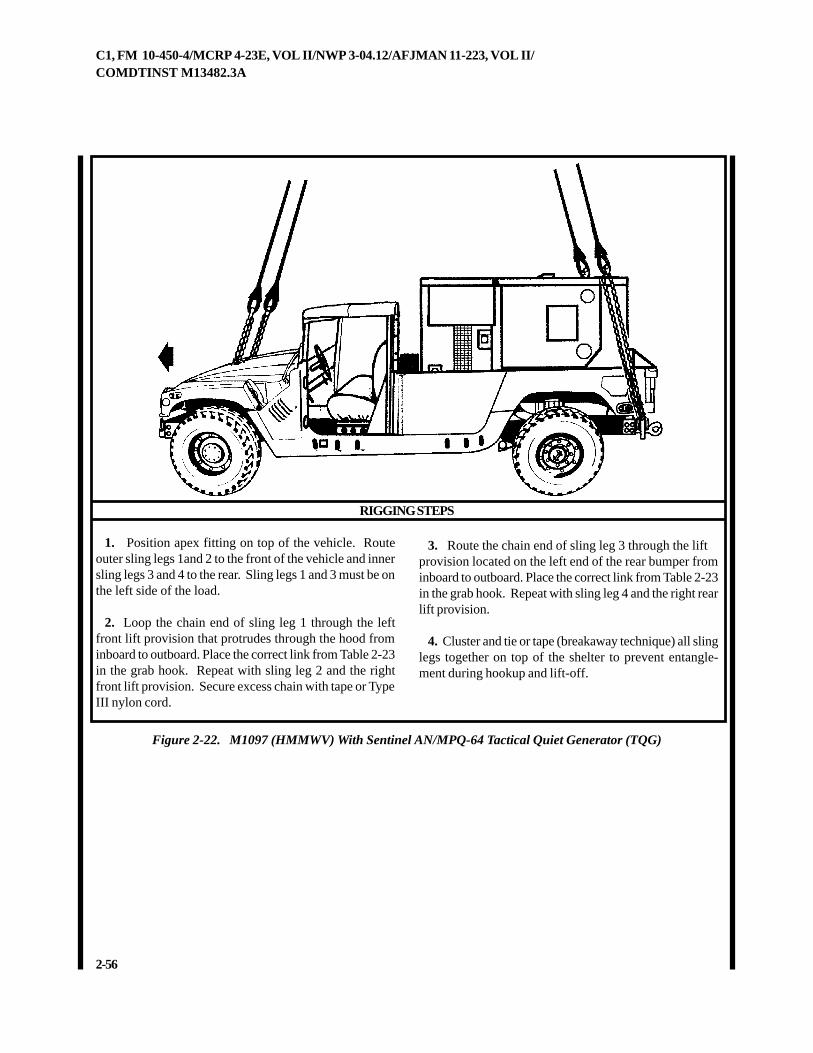
Figure 2-22. M1097 (HMMWV) With Sentinel AN/MPQ-64 Tactical Quiet Generator (TQG)
1. Position apex fitting on top of the vehicle. Routeouter sling legs 1and 2 to the front of the vehicle and innersling legs 3 and 4 to the rear. Sling legs 1 and 3 must be onthe left side of the load.
2. Loop the chain end of sling leg 1 through the leftfront lift provision that protrudes through the hood frominboard to outboard. Place the correct link from Table 2-23in the grab hook. Repeat with sling leg 2 and the rightfront lift provision. Secure excess chain with tape or TypeIII nylon cord.
3. Route the chain end of sling leg 3 through the liftprovision located on the left end of the rear bumper frominboard to outboard. Place the correct link from Table 2-23in the grab hook. Repeat with sling leg 4 and the right rearlift provision.
4. Cluster and tie or tape (breakaway technique) all slinglegs together on top of the shelter to prevent entangle-ment during hookup and lift-off.
C1, FM 10-450-4/MCRP 4-23E, VOL II/NWP 3-04.12/AFJMAN 11-223, VOL II/COMDTINST M13482.3A
2-57
2-25. M1097A2 (HMMWV) With Secure Mobile Anti-Jam Tactical Terminal (SMART-T)Pallet
a. Applicability. The following item in Table 2-24 is certified for all helicopters with suitable lift capacity by the USArmy Soldier Systems Center:
Table 2-24. M1097A2 (HMMWV) With Secure Mobile Anti-Jam Tactical Terminal (SMART-T) Pallet
b. Materials. The following materials are required to rigthis load:
(1) Sling set (10,000-pound capacity).
(2) Tape, adhesive, pressure-sensitive, 2-inch wideroll.
(3) Cord, nylon, Type III, 550-pound breaking strength.
(4) Webbing, cotton, 1/4-inch, 80-pound breakingstrength.
c. Personnel. Two persons can prepare and rig thisload in 10 minutes.
d. Procedures. The following procedures apply tothis load:
(1) Preparation. Prepare the load using the followingsteps:
(a) Fold mirrors forward in front of the windshield foradded protection and tie together with Type III nylon cord.
(b) Secure all equipment and cargo inside thevehicle with tape, nylon cord, or lashings. Remove andsecure the doors in the cab of the vehicle.
(c) Ensure the fuel tank is not over 3/4 full. Inspectfuel tank cap, oil filler cap, and battery caps for properinstallation.
(d) Engage the vehicle parking brake and put thetransmission in neutral.
(e) Ensure the front wheels are pointed straight ahead.Tie down the steering wheel, using the securing deviceattached under the dashboard.
(f) Secure all loose equipment on the SMART-T withtape or Type III nylon cord.
(g) Tape the windshield in an X formation from cor-ner to corner. Tape all mirrors, lights and gauges. Re-move and secure the rear cabin window.
(h) Secure the antenna dish.
(2) Rigging. Rig the load according to the steps inFigure 2-23.
(3) Hookup. The hookup team stands on the vehicle.The static wand person discharges the static electricitywith the static wand. The hookup person places the apexfitting onto the aircraft cargo hook. The hookup teamthen carefully dismounts the vehicle and remains close tothe load as the helicopter removes slack from the slinglegs. When successful hookup is assured, the hookupteam quickly exits the area underneath the helicopter tothe designated rendezvous point.
(4) Derigging. Derigging is the reverse of the prepara-tion and rigging procedures in steps d (1) and d (2).
ERUTALCNEMON ERUTALCNEMON ERUTALCNEMON ERUTALCNEMON ERUTALCNEMONXAM XAM XAM XAM XAM
THGIEW)SDNUOP(
TESGNILS TESGNILS TESGNILS TESGNILS TESGNILSTNUOCKNIL TNUOCKNIL TNUOCKNIL TNUOCKNIL TNUOCKNILRAER/TNORF
DEDNEMMOCER DEDNEMMOCER DEDNEMMOCER DEDNEMMOCER DEDNEMMOCERDEEPSRIA)STONK(
eruceShtiW)VWMMH(2A7901MlanimreTlacitcaTmaJ-itnAeliboM
)T-TRAMS( tellaP045,8 K01 3/03 001
2-58
C1, FM 10-450-4/MCRP 4-23E, VOL II/NWP 3-04.12/AFJMAN 11-223, VOL II/COMDTINST M13482.3A
RIGGING STEPS
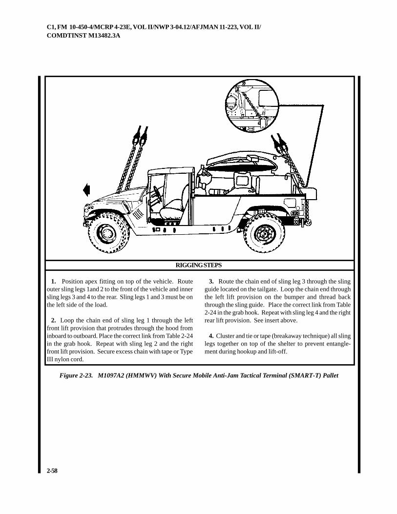
Figure 2-23. M1097A2 (HMMWV) With Secure Mobile Anti-Jam Tactical Terminal (SMART-T) Pallet
1. Position apex fitting on top of the vehicle. Routeouter sling legs 1and 2 to the front of the vehicle and innersling legs 3 and 4 to the rear. Sling legs 1 and 3 must be onthe left side of the load.
2. Loop the chain end of sling leg 1 through the leftfront lift provision that protrudes through the hood frominboard to outboard. Place the correct link from Table 2-24in the grab hook. Repeat with sling leg 2 and the rightfront lift provision. Secure excess chain with tape or TypeIII nylon cord.
3. Route the chain end of sling leg 3 through the slingguide located on the tailgate. Loop the chain end throughthe left lift provision on the bumper and thread backthrough the sling guide. Place the correct link from Table2-24 in the grab hook. Repeat with sling leg 4 and the rightrear lift provision. See insert above.
4. Cluster and tie or tape (breakaway technique) all slinglegs together on top of the shelter to prevent entangle-ment during hookup and lift-off.
C1, FM 10-450-4/MCRP 4-23E, VOL II/NWP 3-04.12/AFJMAN 11-223, VOL II/COMDTINST M13482.3A
2-59
2-26. M1097A1 (HMMWV) With Remote Landing Site Tower (RLST)
a. Applicability. The following item in Table 2-25 is certified for all helicopters with suitable lift capacity by the USArmy Soldier Systems Center:
Table 2-25. M1097A1 (HMMWV) With Remote Landing Site Tower (RLST)
b. Materials. The following materials are required to rigthis load:
(1) Sling set (15,000-pound capacity).
(a) Chain length, part number 34080-4, from 15,000-pound capacity sling sets (8 each).
(b) Coupling link, part number 31611, from 15,000-pound capacity sling sets (8 each).
(2) Tape, adhesive, pressure-sensitive, 2-inch wideroll.
(3) Cord, nylon, Type III, 550-pound breaking strength.
(4) Webbing, cotton, 1/4-inch, 80-pound breakingstrength.
(5) Felt sheet, cattle hair, Type IV, 1/2-inch or suitablepadding.
c. Personnel. Two persons can prepare and rig thisload in 15 minutes.
d. Procedures. The following procedures apply tothis load:
(1) Preparation. Prepare the load using the followingsteps:
(a) Fold mirrors forward in front of the windshield foradded protection and tie together with Type III nylon cord.
(b) Secure all equipment and cargo inside the
vehicle with tape, nylon cord, or lashings. Remove andsecure the doors in the cab of the vehicle.
(c) Ensure the fuel tank is not over 3/4 full. Inspectfuel tank cap, oil filler cap, and battery caps for properinstallation.
(d) Engage the vehicle parking brake and put thetransmission in neutral.
(e) Ensure the front wheels are pointed straight ahead.Tie down the steering wheel, using the securing deviceattached under the dashboard.
(f) Install the lift provisions on the outer ends of therear bumper by removing the tiedown provisions locatedinboard of the bumper end and installing them on theouter ends of the rear bumper.
(g) Configure the RLST in the TRANSPORT mode inaccordance with the operator's manual.
(h) Ensure the RLST is properly secured to the ve-hicle. Secure all equipment inside the RLST with the hold-down straps, tape, or Type III nylon cord.
(i) Secure the RLST cover with the straps provided.Secure the loose ends with tape.
(j) Tape the windshield in an X formation from cor-ner to corner.
(k) Extend the sling leg chains by connecting twoadditional chain lengths to each chain with coupling links.
ERUTALCNEMON ERUTALCNEMON ERUTALCNEMON ERUTALCNEMON ERUTALCNEMONXAM XAM XAM XAM XAM
THGIEW)SDNUOP(
TESGNILS TESGNILS TESGNILS TESGNILS TESGNILSTNUOCKNIL TNUOCKNIL TNUOCKNIL TNUOCKNIL TNUOCKNILRAER/TNORF
DEDNEMMOCER DEDNEMMOCER DEDNEMMOCER DEDNEMMOCER DEDNEMMOCERDEEPSRIA)STONK(
etomeRhtiW)VWMMH(1A7901M)TSLR(rewoTetiSgnidnaL
064,8 K51 3/06 021
2-60
C1, FM 10-450-4/MCRP 4-23E, VOL II/NWP 3-04.12/AFJMAN 11-223, VOL II/COMDTINST M13482.3A
RIGGING STEPS
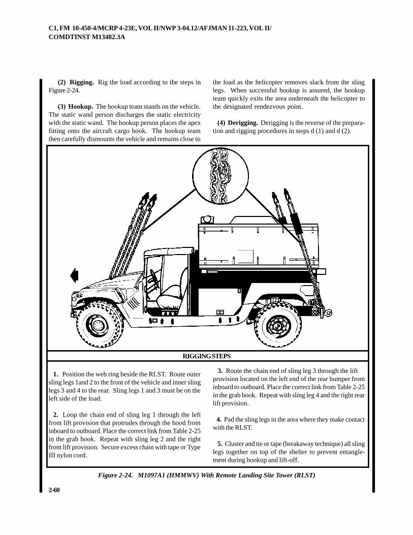
Figure 2-24. M1097A1 (HMMWV) With Remote Landing Site Tower (RLST)
1. Position the web ring beside the RLST. Route outersling legs 1and 2 to the front of the vehicle and inner slinglegs 3 and 4 to the rear. Sling legs 1 and 3 must be on theleft side of the load.
2. Loop the chain end of sling leg 1 through the leftfront lift provision that protrudes through the hood frominboard to outboard. Place the correct link from Table 2-25in the grab hook. Repeat with sling leg 2 and the rightfront lift provision. Secure excess chain with tape or TypeIII nylon cord.
3. Route the chain end of sling leg 3 through the liftprovision located on the left end of the rear bumper frominboard to outboard. Place the correct link from Table 2-25in the grab hook. Repeat with sling leg 4 and the right rearlift provision.
4. Pad the sling legs in the area where they make contactwith the RLST.
5. Cluster and tie or tape (breakaway technique) all slinglegs together on top of the shelter to prevent entangle-ment during hookup and lift-off.
(2) Rigging. Rig the load according to the steps inFigure 2-24.
(3) Hookup. The hookup team stands on the vehicle.The static wand person discharges the static electricitywith the static wand. The hookup person places the apexfitting onto the aircraft cargo hook. The hookup teamthen carefully dismounts the vehicle and remains close to
the load as the helicopter removes slack from the slinglegs. When successful hookup is assured, the hookupteam quickly exits the area underneath the helicopter tothe designated rendezvous point.
(4) Derigging. Derigging is the reverse of the prepara-tion and rigging procedures in steps d (1) and d (2).
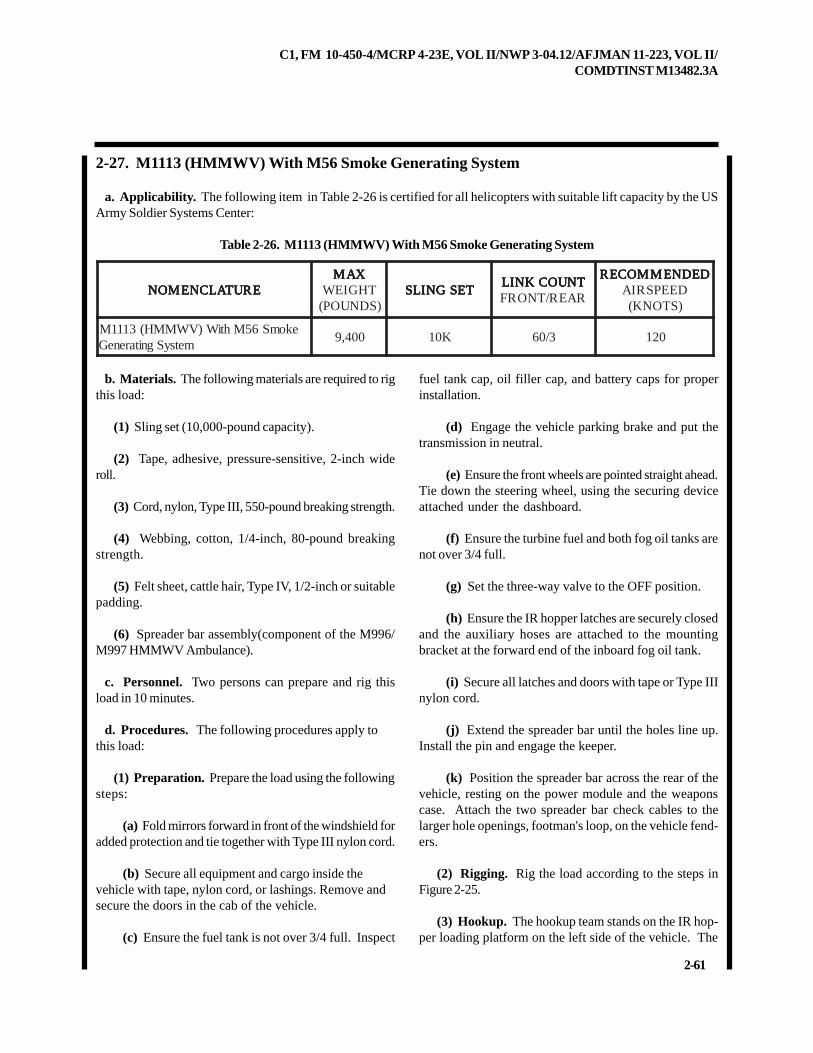
C1, FM 10-450-4/MCRP 4-23E, VOL II/NWP 3-04.12/AFJMAN 11-223, VOL II/COMDTINST M13482.3A
2-61
2-27. M1113 (HMMWV) With M56 Smoke Generating System
a. Applicability. The following item in Table 2-26 is certified for all helicopters with suitable lift capacity by the USArmy Soldier Systems Center:
Table 2-26. M1113 (HMMWV) With M56 Smoke Generating System
ERUTALCNEMON ERUTALCNEMON ERUTALCNEMON ERUTALCNEMON ERUTALCNEMONXAM XAM XAM XAM XAM
THGIEW)SDNUOP(
TESGNILS TESGNILS TESGNILS TESGNILS TESGNILSTNUOCKNIL TNUOCKNIL TNUOCKNIL TNUOCKNIL TNUOCKNILRAER/TNORF
DEDNEMMOCER DEDNEMMOCER DEDNEMMOCER DEDNEMMOCER DEDNEMMOCERDEEPSRIA)STONK(
ekomS65MhtiW)VWMMH(3111MmetsySgnitareneG
004,9 K01 3/06 021
b. Materials. The following materials are required to rigthis load:
(1) Sling set (10,000-pound capacity).
(2) Tape, adhesive, pressure-sensitive, 2-inch wideroll.
(3) Cord, nylon, Type III, 550-pound breaking strength.
(4) Webbing, cotton, 1/4-inch, 80-pound breakingstrength.
(5) Felt sheet, cattle hair, Type IV, 1/2-inch or suitablepadding.
(6) Spreader bar assembly(component of the M996/M997 HMMWV Ambulance).
c. Personnel. Two persons can prepare and rig thisload in 10 minutes.
d. Procedures. The following procedures apply tothis load:
(1) Preparation. Prepare the load using the followingsteps:
(a) Fold mirrors forward in front of the windshield foradded protection and tie together with Type III nylon cord.
(b) Secure all equipment and cargo inside thevehicle with tape, nylon cord, or lashings. Remove andsecure the doors in the cab of the vehicle.
(c) Ensure the fuel tank is not over 3/4 full. Inspect
fuel tank cap, oil filler cap, and battery caps for properinstallation.
(d) Engage the vehicle parking brake and put thetransmission in neutral.
(e) Ensure the front wheels are pointed straight ahead.Tie down the steering wheel, using the securing deviceattached under the dashboard.
(f) Ensure the turbine fuel and both fog oil tanks arenot over 3/4 full.
(g) Set the three-way valve to the OFF position.
(h) Ensure the IR hopper latches are securely closedand the auxiliary hoses are attached to the mountingbracket at the forward end of the inboard fog oil tank.
(i) Secure all latches and doors with tape or Type IIInylon cord.
(j) Extend the spreader bar until the holes line up.Install the pin and engage the keeper.
(k) Position the spreader bar across the rear of thevehicle, resting on the power module and the weaponscase. Attach the two spreader bar check cables to thelarger hole openings, footman's loop, on the vehicle fend-ers.
(2) Rigging. Rig the load according to the steps inFigure 2-25.
(3) Hookup. The hookup team stands on the IR hop-per loading platform on the left side of the vehicle. The
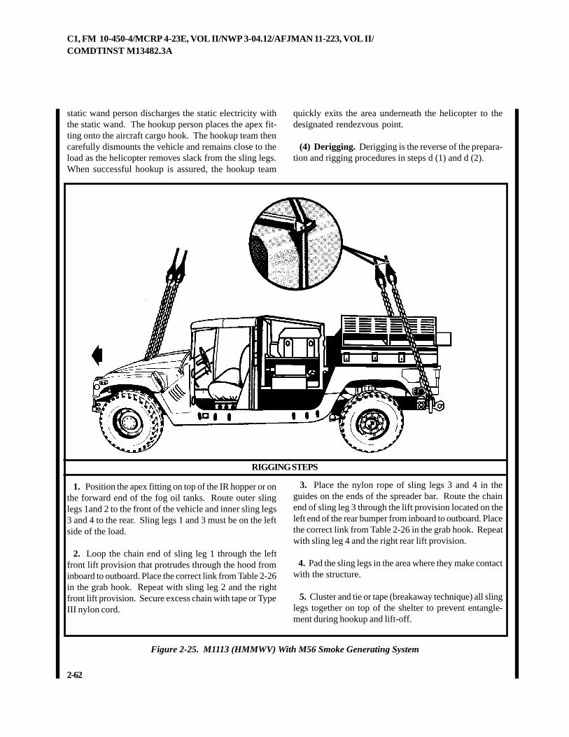
2-62
C1, FM 10-450-4/MCRP 4-23E, VOL II/NWP 3-04.12/AFJMAN 11-223, VOL II/COMDTINST M13482.3A
static wand person discharges the static electricity withthe static wand. The hookup person places the apex fit-ting onto the aircraft cargo hook. The hookup team thencarefully dismounts the vehicle and remains close to theload as the helicopter removes slack from the sling legs.When successful hookup is assured, the hookup team
quickly exits the area underneath the helicopter to thedesignated rendezvous point.
(4) Derigging. Derigging is the reverse of the prepara-tion and rigging procedures in steps d (1) and d (2).
Figure 2-25. M1113 (HMMWV) With M56 Smoke Generating System
RIGGING STEPS
1. Position the apex fitting on top of the IR hopper or onthe forward end of the fog oil tanks. Route outer slinglegs 1and 2 to the front of the vehicle and inner sling legs3 and 4 to the rear. Sling legs 1 and 3 must be on the leftside of the load.
2. Loop the chain end of sling leg 1 through the leftfront lift provision that protrudes through the hood frominboard to outboard. Place the correct link from Table 2-26in the grab hook. Repeat with sling leg 2 and the rightfront lift provision. Secure excess chain with tape or TypeIII nylon cord.
3. Place the nylon rope of sling legs 3 and 4 in theguides on the ends of the spreader bar. Route the chainend of sling leg 3 through the lift provision located on theleft end of the rear bumper from inboard to outboard. Placethe correct link from Table 2-26 in the grab hook. Repeatwith sling leg 4 and the right rear lift provision.
4. Pad the sling legs in the area where they make contactwith the structure.
5. Cluster and tie or tape (breakaway technique) all slinglegs together on top of the shelter to prevent entangle-ment during hookup and lift-off.
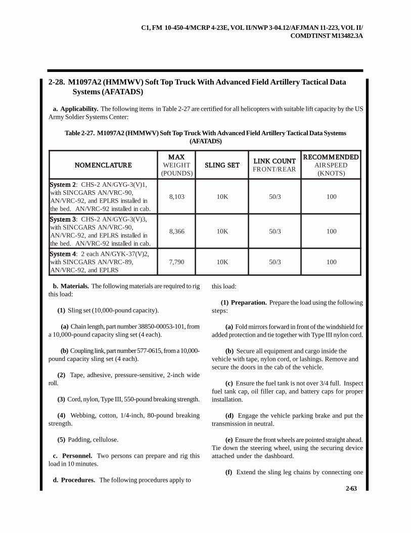
C1, FM 10-450-4/MCRP 4-23E, VOL II/NWP 3-04.12/AFJMAN 11-223, VOL II/COMDTINST M13482.3A
2-63
2-28. M1097A2 (HMMWV) Soft Top Truck With Advanced Field Artillery Tactical DataSystems (AFATADS)
a. Applicability. The following items in Table 2-27 are certified for all helicopters with suitable lift capacity by the USArmy Soldier Systems Center:
Table 2-27. M1097A2 (HMMWV) Soft Top Truck With Advanced Field Artillery Tactical Data Systems(AFATADS)
ERUTALCNEMON ERUTALCNEMON ERUTALCNEMON ERUTALCNEMON ERUTALCNEMONXAM XAM XAM XAM XAM
THGIEW)SDNUOP(
TESGNILS TESGNILS TESGNILS TESGNILS TESGNILSTNUOCKNIL TNUOCKNIL TNUOCKNIL TNUOCKNIL TNUOCKNILRAER/TNORF
DEDNEMMOCER DEDNEMMOCER DEDNEMMOCER DEDNEMMOCER DEDNEMMOCERDEEPSRIA)STONK(
2metsyS 2metsyS 2metsyS 2metsyS 2metsyS ,1)V(3-GYG/NA2-SHC:,09-CRV/NASRAGCNIShtiw
nidellatsniSRLPEdna,29-CRV/NA.bacnidellatsni29-CRV/NA.debeht
301,8 K01 3/05 001
3metsyS 3metsyS 3metsyS 3metsyS 3metsyS ,3)V(3-GYG/NA2-SHC:,09-CRV/NASRAGCNIShtiw
nidellatsniSRLPEdna,29-CRV/NA.bacnidellatsni29-CRV/NA.debeht
663,8 K01 3/05 001
4metsyS 4metsyS 4metsyS 4metsyS 4metsyS ,2)V(73-KYG/NAhcae2:,98-CRV/NASRAGCNIShtiw
SRLPEdna,29-CRV/NA097,7 K01 3/05 001
b. Materials. The following materials are required to rigthis load:
(1) Sling set (10,000-pound capacity).
(a) Chain length, part number 38850-00053-101, froma 10,000-pound capacity sling set (4 each).
(b) Coupling link, part number 577-0615, from a 10,000-pound capacity sling set (4 each).
(2) Tape, adhesive, pressure-sensitive, 2-inch wideroll.
(3) Cord, nylon, Type III, 550-pound breaking strength.
(4) Webbing, cotton, 1/4-inch, 80-pound breakingstrength.
(5) Padding, cellulose.
c. Personnel. Two persons can prepare and rig thisload in 10 minutes.
d. Procedures. The following procedures apply to
this load:
(1) Preparation. Prepare the load using the followingsteps:
(a) Fold mirrors forward in front of the windshield foradded protection and tie together with Type III nylon cord.
(b) Secure all equipment and cargo inside thevehicle with tape, nylon cord, or lashings. Remove andsecure the doors in the cab of the vehicle.
(c) Ensure the fuel tank is not over 3/4 full. Inspectfuel tank cap, oil filler cap, and battery caps for properinstallation.
(d) Engage the vehicle parking brake and put thetransmission in neutral.
(e) Ensure the front wheels are pointed straight ahead.Tie down the steering wheel, using the securing deviceattached under the dashboard.
(f) Extend the sling leg chains by connecting one
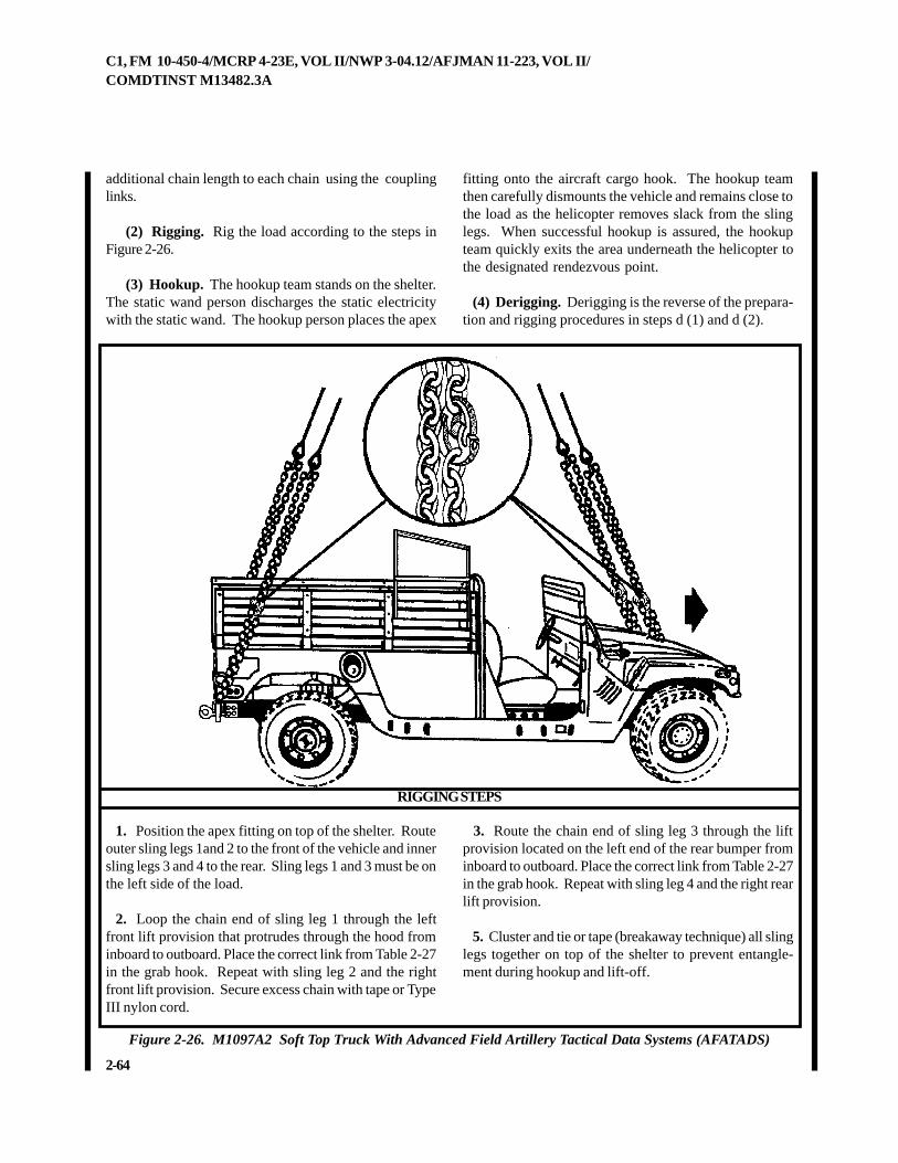
2-64
C1, FM 10-450-4/MCRP 4-23E, VOL II/NWP 3-04.12/AFJMAN 11-223, VOL II/COMDTINST M13482.3A
additional chain length to each chain using the couplinglinks.
(2) Rigging. Rig the load according to the steps inFigure 2-26.
(3) Hookup. The hookup team stands on the shelter.The static wand person discharges the static electricitywith the static wand. The hookup person places the apex
fitting onto the aircraft cargo hook. The hookup teamthen carefully dismounts the vehicle and remains close tothe load as the helicopter removes slack from the slinglegs. When successful hookup is assured, the hookupteam quickly exits the area underneath the helicopter tothe designated rendezvous point.
(4) Derigging. Derigging is the reverse of the prepara-tion and rigging procedures in steps d (1) and d (2).
RIGGING STEPS
Figure 2-26. M1097A2 Soft Top Truck With Advanced Field Artillery Tactical Data Systems (AFATADS)
1. Position the apex fitting on top of the shelter. Routeouter sling legs 1and 2 to the front of the vehicle and innersling legs 3 and 4 to the rear. Sling legs 1 and 3 must be onthe left side of the load.
2. Loop the chain end of sling leg 1 through the leftfront lift provision that protrudes through the hood frominboard to outboard. Place the correct link from Table 2-27in the grab hook. Repeat with sling leg 2 and the rightfront lift provision. Secure excess chain with tape or TypeIII nylon cord.
3. Route the chain end of sling leg 3 through the liftprovision located on the left end of the rear bumper frominboard to outboard. Place the correct link from Table 2-27in the grab hook. Repeat with sling leg 4 and the right rearlift provision.
5. Cluster and tie or tape (breakaway technique) all slinglegs together on top of the shelter to prevent entangle-ment during hookup and lift-off.
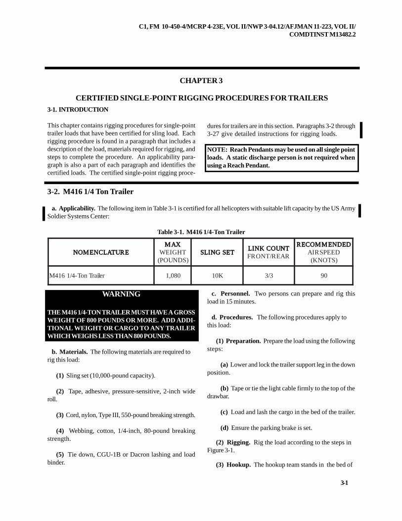
C1, FM 10-450-4/MCRP 4-23E, VOL II/NWP 3-04.12/AFJMAN 11-223, VOL II/COMDTINST M13482.2
3-1
CHAPTER 3
CERTIFIED SINGLE-POINT RIGGING PROCEDURES FOR TRAILERS3-1. INTRODUCTION
This chapter contains rigging procedures for single-pointtrailer loads that have been certified for sling load. Eachrigging procedure is found in a paragraph that includes adescription of the load, materials required for rigging, andsteps to complete the procedure. An applicability para-graph is also a part of each paragraph and identifies thecertified loads. The certified single-point rigging proce-
3-2. M416 1/4 Ton Trailer
a. Applicability. The following item in Table 3-1 is certified for all helicopters with suitable lift capacity by the US ArmySoldier Systems Center:
Table 3-1. M416 1/4-Ton Trailer
WARNING
THE M416 1/4-TON TRAILER MUST HAVE A GROSSWEIGHT OF 800 POUNDS OR MORE. ADD ADDI-TIONAL WEIGHT OR CARGO TO ANY TRAILERWHICH WEIGHS LESS THAN 800 POUNDS.
b. Materials. The following materials are required torig this load:
(1) Sling set (10,000-pound capacity).
(2) Tape, adhesive, pressure-sensitive, 2-inch wideroll.
(3) Cord, nylon, Type III, 550-pound breaking strength.
(4) Webbing, cotton, 1/4-inch, 80-pound breakingstrength.
(5) Tie down, CGU-1B or Dacron lashing and loadbinder.
c. Personnel. Two persons can prepare and rig thisload in 15 minutes.
d. Procedures. The following procedures apply tothis load:
(1) Preparation. Prepare the load using the followingsteps:
(a) Lower and lock the trailer support leg in the downposition.
(b) Tape or tie the light cable firmly to the top of thedrawbar.
(c) Load and lash the cargo in the bed of the trailer.
(d) Ensure the parking brake is set.
(2) Rigging. Rig the load according to the steps inFigure 3-1.
(3) Hookup. The hookup team stands in the bed of
dures for trailers are in this section. Paragraphs 3-2 through3-27 give detailed instructions for rigging loads.
NOTE: Reach Pendants may be used on all single pointloads. A static discharge person is not required whenusing a Reach Pendant.
ERUTALCNEMON ERUTALCNEMON ERUTALCNEMON ERUTALCNEMON ERUTALCNEMONXAM XAM XAM XAM XAM
THGIEW)SDNUOP(
TESGNILS TESGNILS TESGNILS TESGNILS TESGNILSTNUOCKNIL TNUOCKNIL TNUOCKNIL TNUOCKNIL TNUOCKNILRAER/TNORF
DEDNEMMOCER DEDNEMMOCER DEDNEMMOCER DEDNEMMOCER DEDNEMMOCERDEEPSRIA)STONK(
reliarTnoT-4/1614M 080,1 K01 3/3 09
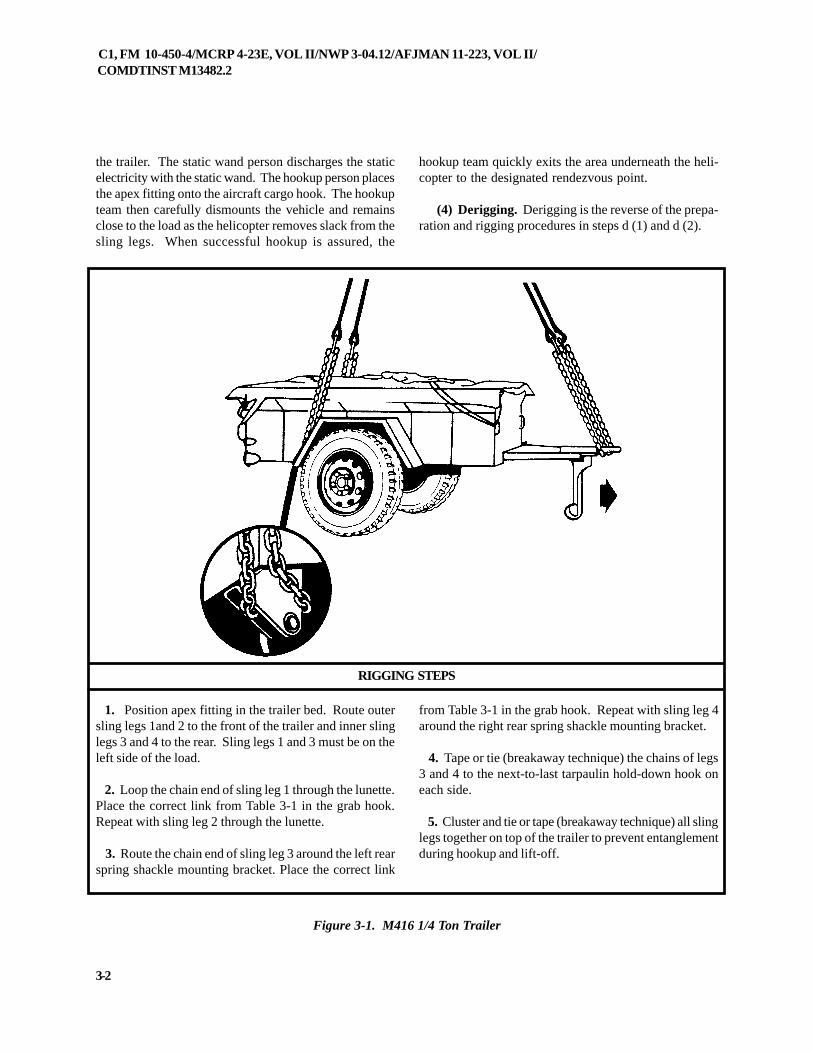
C1, FM 10-450-4/MCRP 4-23E, VOL II/NWP 3-04.12/AFJMAN 11-223, VOL II/COMDTINST M13482.2
3-2
1. Position apex fitting in the trailer bed. Route outersling legs 1and 2 to the front of the trailer and inner slinglegs 3 and 4 to the rear. Sling legs 1 and 3 must be on theleft side of the load.
2. Loop the chain end of sling leg 1 through the lunette.Place the correct link from Table 3-1 in the grab hook.Repeat with sling leg 2 through the lunette.
3. Route the chain end of sling leg 3 around the left rearspring shackle mounting bracket. Place the correct link
RIGGING STEPS
Figure 3-1. M416 1/4 Ton Trailer
the trailer. The static wand person discharges the staticelectricity with the static wand. The hookup person placesthe apex fitting onto the aircraft cargo hook. The hookupteam then carefully dismounts the vehicle and remainsclose to the load as the helicopter removes slack from thesling legs. When successful hookup is assured, the
hookup team quickly exits the area underneath the heli-copter to the designated rendezvous point.
(4) Derigging. Derigging is the reverse of the prepa-ration and rigging procedures in steps d (1) and d (2).
from Table 3-1 in the grab hook. Repeat with sling leg 4around the right rear spring shackle mounting bracket.
4. Tape or tie (breakaway technique) the chains of legs3 and 4 to the next-to-last tarpaulin hold-down hook oneach side.
5. Cluster and tie or tape (breakaway technique) all slinglegs together on top of the trailer to prevent entanglementduring hookup and lift-off.
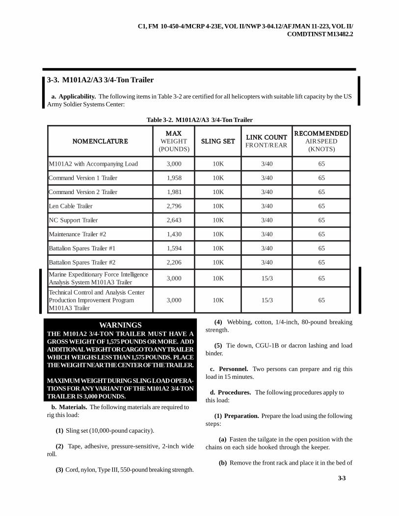
C1, FM 10-450-4/MCRP 4-23E, VOL II/NWP 3-04.12/AFJMAN 11-223, VOL II/COMDTINST M13482.2
3-3
3-3. M101A2/A3 3/4-Ton Trailer
a. Applicability. The following items in Table 3-2 are certified for all helicopters with suitable lift capacity by the USArmy Soldier Systems Center:
Table 3-2. M101A2/A3 3/4-Ton Trailer
WARNINGSTHE M101A2 3/4-TON TRAILER MUST HAVE AGROSS WEIGHT OF 1,575 POUNDS OR MORE. ADDADDITIONAL WEIGHT OR CARGO TO ANY TRAILERWHICH WEIGHS LESS THAN 1,575 POUNDS. PLACETHE WEIGHT NEAR THE CENTER OF THE TRAILER.
MAXIMUM WEIGHT DURING SLING LOAD OPERA-TIONS FOR ANY VARIANT OF THE M101A2 3/4-TONTRAILER IS 3,000 POUNDS.
b. Materials. The following materials are required torig this load:
(1) Sling set (10,000-pound capacity).
(2) Tape, adhesive, pressure-sensitive, 2-inch wideroll.
(3) Cord, nylon, Type III, 550-pound breaking strength.
(4) Webbing, cotton, 1/4-inch, 80-pound breakingstrength.
(5) Tie down, CGU-1B or dacron lashing and loadbinder.
c. Personnel. Two persons can prepare and rig thisload in 15 minutes.
d. Procedures. The following procedures apply tothis load:
(1) Preparation. Prepare the load using the followingsteps:
(a) Fasten the tailgate in the open position with thechains on each side hooked through the keeper.
(b) Remove the front rack and place it in the bed of
ERUTALCNEMON ERUTALCNEMON ERUTALCNEMON ERUTALCNEMON ERUTALCNEMONXAM XAM XAM XAM XAM
THGIEW)SDNUOP(
TESGNILS TESGNILS TESGNILS TESGNILS TESGNILSTNUOCKNIL TNUOCKNIL TNUOCKNIL TNUOCKNIL TNUOCKNILRAER/TNORF
DEDNEMMOCER DEDNEMMOCER DEDNEMMOCER DEDNEMMOCER DEDNEMMOCERDEEPSRIA)STONK(
daoLgniynapmoccAhtiw2A101M 000,3 K01 04/3 56
reliarT1noisreVdnammoC 859,1 K01 04/3 56
reliarT2noisreVdnammoC 189,1 K01 04/3 56
reliarTelbaCneL 697,2 K01 04/3 56
reliarTtroppuSCN 346,2 K01 04/3 56
2#reliarTecnanetniaM 034,1 K01 04/3 56
1#reliarTserapSnoilattaB 495,1 K01 04/3 56
2#reliarTserapSnoilattaB 602,2 K01 04/3 56
ecnegilletnIecroFyranoitidepxEeniraMreliarT3A101MmetsySsisylanA
000,3 K01 3/51 56
retneCsisylanAdnalortnoClacinhceTmargorPtnemevorpmInoitcudorP
reliarT3A101M000,3 K01 3/51 56
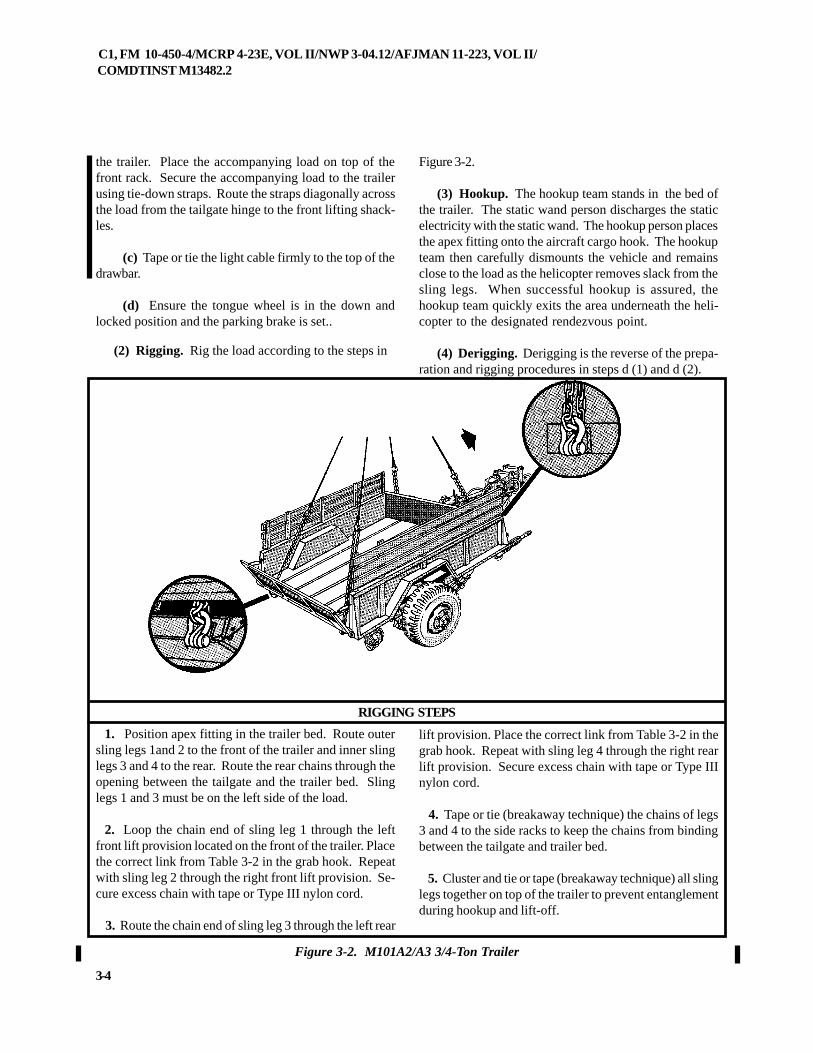
C1, FM 10-450-4/MCRP 4-23E, VOL II/NWP 3-04.12/AFJMAN 11-223, VOL II/COMDTINST M13482.2
3-4
the trailer. Place the accompanying load on top of thefront rack. Secure the accompanying load to the trailerusing tie-down straps. Route the straps diagonally acrossthe load from the tailgate hinge to the front lifting shack-les.
(c) Tape or tie the light cable firmly to the top of thedrawbar.
(d) Ensure the tongue wheel is in the down andlocked position and the parking brake is set..
(2) Rigging. Rig the load according to the steps in
Figure 3-2.
(3) Hookup. The hookup team stands in the bed ofthe trailer. The static wand person discharges the staticelectricity with the static wand. The hookup person placesthe apex fitting onto the aircraft cargo hook. The hookupteam then carefully dismounts the vehicle and remainsclose to the load as the helicopter removes slack from thesling legs. When successful hookup is assured, thehookup team quickly exits the area underneath the heli-copter to the designated rendezvous point.
(4) Derigging. Derigging is the reverse of the prepa-ration and rigging procedures in steps d (1) and d (2).
Figure 3-2. M101A2/A3 3/4-Ton Trailer
1. Position apex fitting in the trailer bed. Route outersling legs 1and 2 to the front of the trailer and inner slinglegs 3 and 4 to the rear. Route the rear chains through theopening between the tailgate and the trailer bed. Slinglegs 1 and 3 must be on the left side of the load.
2. Loop the chain end of sling leg 1 through the leftfront lift provision located on the front of the trailer. Placethe correct link from Table 3-2 in the grab hook. Repeatwith sling leg 2 through the right front lift provision. Se-cure excess chain with tape or Type III nylon cord.
3. Route the chain end of sling leg 3 through the left rear
lift provision. Place the correct link from Table 3-2 in thegrab hook. Repeat with sling leg 4 through the right rearlift provision. Secure excess chain with tape or Type IIInylon cord.
4. Tape or tie (breakaway technique) the chains of legs3 and 4 to the side racks to keep the chains from bindingbetween the tailgate and trailer bed.
5. Cluster and tie or tape (breakaway technique) all slinglegs together on top of the trailer to prevent entanglementduring hookup and lift-off.
RIGGING STEPS
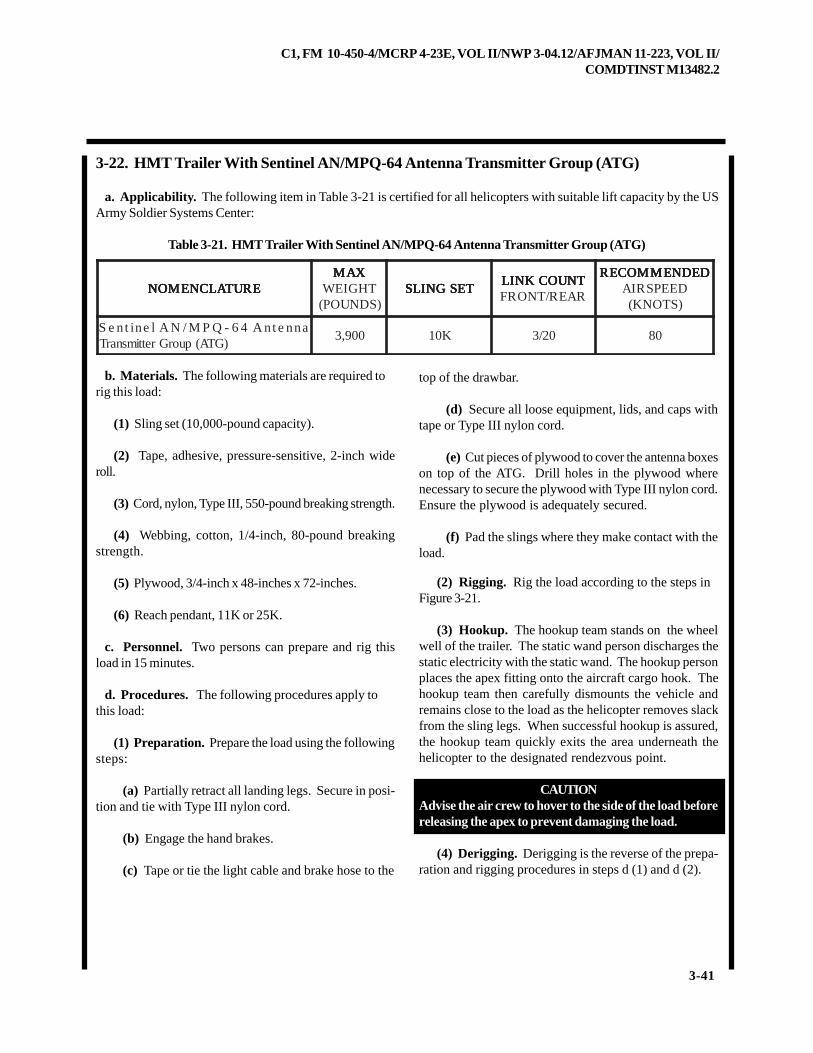
C1, FM 10-450-4/MCRP 4-23E, VOL II/NWP 3-04.12/AFJMAN 11-223, VOL II/COMDTINST M13482.2
3-41
3-22. HMT Trailer With Sentinel AN/MPQ-64 Antenna Transmitter Group (ATG)
a. Applicability. The following item in Table 3-21 is certified for all helicopters with suitable lift capacity by the USArmy Soldier Systems Center:
Table 3-21. HMT Trailer With Sentinel AN/MPQ-64 Antenna Transmitter Group (ATG)
b. Materials. The following materials are required torig this load:
(1) Sling set (10,000-pound capacity).
(2) Tape, adhesive, pressure-sensitive, 2-inch wideroll.
(3) Cord, nylon, Type III, 550-pound breaking strength.
(4) Webbing, cotton, 1/4-inch, 80-pound breakingstrength.
(5) Plywood, 3/4-inch x 48-inches x 72-inches.
(6) Reach pendant, 11K or 25K.
c. Personnel. Two persons can prepare and rig thisload in 15 minutes.
d. Procedures. The following procedures apply tothis load:
(1) Preparation. Prepare the load using the followingsteps:
(a) Partially retract all landing legs. Secure in posi-tion and tie with Type III nylon cord.
(b) Engage the hand brakes.
(c) Tape or tie the light cable and brake hose to the
top of the drawbar.
(d) Secure all loose equipment, lids, and caps withtape or Type III nylon cord.
(e) Cut pieces of plywood to cover the antenna boxeson top of the ATG. Drill holes in the plywood wherenecessary to secure the plywood with Type III nylon cord.Ensure the plywood is adequately secured.
(f) Pad the slings where they make contact with theload.
(2) Rigging. Rig the load according to the steps inFigure 3-21.
(3) Hookup. The hookup team stands on the wheelwell of the trailer. The static wand person discharges thestatic electricity with the static wand. The hookup personplaces the apex fitting onto the aircraft cargo hook. Thehookup team then carefully dismounts the vehicle andremains close to the load as the helicopter removes slackfrom the sling legs. When successful hookup is assured,the hookup team quickly exits the area underneath thehelicopter to the designated rendezvous point.
CAUTIONAdvise the air crew to hover to the side of the load beforereleasing the apex to prevent damaging the load.
(4) Derigging. Derigging is the reverse of the prepa-ration and rigging procedures in steps d (1) and d (2).
ERUTALCNEMON ERUTALCNEMON ERUTALCNEMON ERUTALCNEMON ERUTALCNEMONXAM XAM XAM XAM XAM
THGIEW)SDNUOP(
TESGNILS TESGNILS TESGNILS TESGNILS TESGNILSTNUOCKNIL TNUOCKNIL TNUOCKNIL TNUOCKNIL TNUOCKNILRAER/TNORF
DEDNEMMOCER DEDNEMMOCER DEDNEMMOCER DEDNEMMOCER DEDNEMMOCERDEEPSRIA)STONK(
annetnA46-QPM/NAlenitneS)GTA(puorGrettimsnarT
009,3 K01 02/3 08
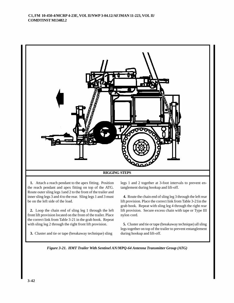
C1, FM 10-450-4/MCRP 4-23E, VOL II/NWP 3-04.12/AFJMAN 11-223, VOL II/COMDTINST M13482.2
3-42
Figure 3-21. HMT Trailer With Sentinel AN/MPQ-64 Antenna Transmitter Group (ATG)
1. Attach a reach pendant to the apex fitting. Positionthe reach pendant and apex fitting on top of the ATG.Route outer sling legs 1and 2 to the front of the trailer andinner sling legs 3 and 4 to the rear. Sling legs 1 and 3 mustbe on the left side of the load.
2. Loop the chain end of sling leg 1 through the leftfront lift provision located on the front of the trailer. Placethe correct link from Table 3-21 in the grab hook. Repeatwith sling leg 2 through the right front lift provision.
3. Cluster and tie or tape (breakaway technique) sling
legs 1 and 2 together at 3-foot intervals to prevent en-tanglement during hookup and lift-off.
4. Route the chain end of sling leg 3 through the left rearlift provision. Place the correct link from Table 3-21in thegrab hook. Repeat with sling leg 4 through the right rearlift provision. Secure excess chain with tape or Type IIInylon cord.
5. Cluster and tie or tape (breakaway technique) all slinglegs together on top of the trailer to prevent entanglementduring hookup and lift-off.
RIGGING STEPS
C1, FM 10-450-4/MCRP 4-23E, VOL II/NWP 3-04.12/AFJMAN 11-223, VOL II/COMDTINST M13482.2
3-43
3-23. HMT Trailer With Remote Landing Site Tower (RLST)
a. Applicability. The following item in Table 3-22 is certified for all helicopters with suitable lift capacity by the USArmy Soldier Systems Center:
Table 3-22. HMT Trailer With Remote Landing Site Tower (RLST)
ERUTALCNEMON ERUTALCNEMON ERUTALCNEMON ERUTALCNEMON ERUTALCNEMONXAM XAM XAM XAM XAM
THGIEW)SDNUOP(
TESGNILS TESGNILS TESGNILS TESGNILS TESGNILSTNUOCKNIL TNUOCKNIL TNUOCKNIL TNUOCKNIL TNUOCKNILRAER/TNORF
DEDNEMMOCER DEDNEMMOCER DEDNEMMOCER DEDNEMMOCER DEDNEMMOCERDEEPSRIA)STONK(
)TSLR(rewoTetiSgnidnaLetomeR 006,3 K51 51/3 021
b. Materials. The following materials are required torig this load:
(1) Sling set (15,000-pound capacity).
(a) Chain length, part number 34080-4, from 15,000-pound capacity sling sets (8 each).
(b) Coupling link, part number 31611, from 15,000-pound capacity sling sets (8 each).
(2) Tape, adhesive, pressure-sensitive, 2-inch wideroll.
(3) Cord, nylon, Type III, 550-pound breaking strength.
(4) Webbing, cotton, 1/4-inch, 80-pound breakingstrength.
(5) Felt sheet, cattle hair, Type IV, 1/2-inch or suitablepadding
c. Personnel. Two persons can prepare and rig thisload in 15 minutes.
d. Procedures. The following procedures apply tothis load:
(1) Preparation. Prepare the load using the followingsteps:
(a) Engage the hand brakes.
(b) Secure loose fittings, wires, and cables with tape
or Type III nylon cord. Tape the trailer lights and the cableon the spool.
(c) Retract the jack wheel to the lowest position.Position the rear stabilizers in the highest position.
(d) Place the cover over the aft rack and secure theloose ends of the straps with tape.
(e) Extend the sling leg chains by connecting twoadditional chain lengths to each chain using the cou-pling links.
(2) Rigging. Rig the load according to the steps inFigure 3-22.
(3) Hookup. The hookup team stands beside the trailer.The static wand person discharges the static electricitywith the static wand. The hookup person places the apexfitting onto the aircraft cargo hook. The hookup teamthen carefully dismounts the vehicle and remains close tothe load as the helicopter removes slack from the slinglegs. When successful hookup is assured, the hookupteam quickly exits the area underneath the helicopter tothe designated rendezvous point.
CAUTIONEnsure the sling legs do not snag on the an-tenna or the pole at the corner of the trailer.
(4) Derigging. Derigging is the reverse of the prepa-ration and rigging procedures in steps d (1) and d (2).
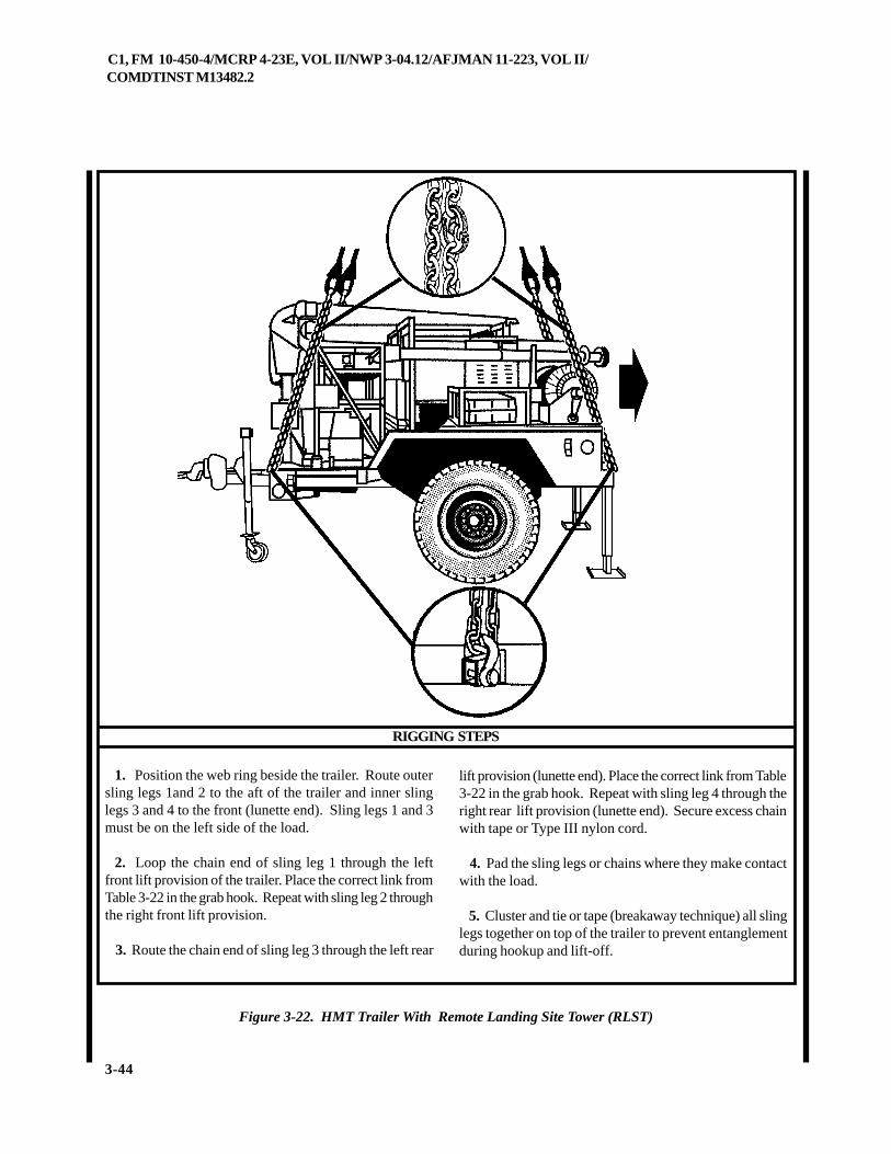
C1, FM 10-450-4/MCRP 4-23E, VOL II/NWP 3-04.12/AFJMAN 11-223, VOL II/COMDTINST M13482.2
3-44
RIGGING STEPS
Figure 3-22. HMT Trailer With Remote Landing Site Tower (RLST)
1. Position the web ring beside the trailer. Route outersling legs 1and 2 to the aft of the trailer and inner slinglegs 3 and 4 to the front (lunette end). Sling legs 1 and 3must be on the left side of the load.
2. Loop the chain end of sling leg 1 through the leftfront lift provision of the trailer. Place the correct link fromTable 3-22 in the grab hook. Repeat with sling leg 2 throughthe right front lift provision.
3. Route the chain end of sling leg 3 through the left rear
lift provision (lunette end). Place the correct link from Table3-22 in the grab hook. Repeat with sling leg 4 through theright rear lift provision (lunette end). Secure excess chainwith tape or Type III nylon cord.
4. Pad the sling legs or chains where they make contactwith the load.
5. Cluster and tie or tape (breakaway technique) all slinglegs together on top of the trailer to prevent entanglementduring hookup and lift-off.
C1, FM 10-450-4/MCRP 4-23E, VOL II/NWP 3-04.12/AFJMAN 11-223, VOL II/COMDTINST M13482.2
3-45
3-24. M105A3 Trailer
a. Applicability. The following item in Table 3-23 is certified for all helicopters with suitable lift capacity by the USArmy Soldier Systems Center:
Table 3-23. M105A3 Trailer
ERUTALCNEMON ERUTALCNEMON ERUTALCNEMON ERUTALCNEMON ERUTALCNEMONXAM XAM XAM XAM XAM
THGIEW)SDNUOP(
TESGNILS TESGNILS TESGNILS TESGNILS TESGNILSTNUOCKNIL TNUOCKNIL TNUOCKNIL TNUOCKNIL TNUOCKNILRAER/TNORF
DEDNEMMOCER DEDNEMMOCER DEDNEMMOCER DEDNEMMOCER DEDNEMMOCERDEEPSRIA)STONK(
ytpmE,reliarT3A501M 006,2 K01 04/3 08
dedaoL,reliarT3A501M 085,5 K01 04/3 011
b. Materials. The following materials are required torig this load:
(1) Sling set (10,000-pound capacity).
(2) Tape, adhesive, pressure-sensitive, 2-inch wideroll.
(3) Cord, nylon, Type III, 550-pound breaking strength.
(4) Webbing, cotton, 1/4-inch, 80-pound breakingstrength.
c. Personnel. Two persons can prepare and rig thisload in 10 minutes.
d. Procedures. The following procedures apply tothis load:
(1) Preparation. Prepare the load using the followingsteps:
(a) Raise the trailer's jack stand so the pintle is on the
ground.
(b) Engage the hand brakes.
(c) Tape or tie the light cable, safety chains, andbrake hose to the top of the drawbar.
(2) Rigging. Rig the load according to the steps inFigure 3-23.
(3) Hookup. The hookup team stands on the trailerbed. The static wand person discharges the static elec-tricity with the static wand. The hookup person placesthe apex fitting onto the aircraft cargo hook. The hookupteam then carefully dismounts the vehicle and remainsclose to the load as the helicopter removes slack from thesling legs. When successful hookup is assured, thehookup team quickly exits the area underneath the heli-copter to the designated rendezvous point.
(4) Derigging. Derigging is the reverse of the prepa-ration and rigging procedures in steps d (1) and d (2).
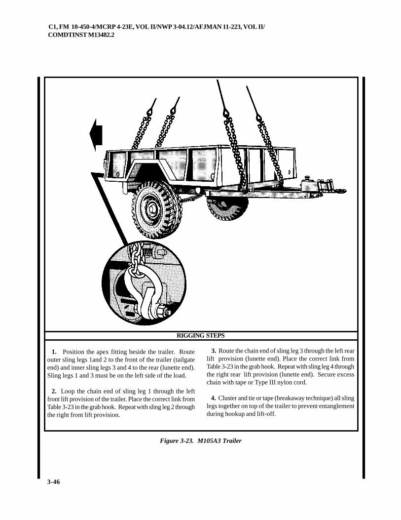
C1, FM 10-450-4/MCRP 4-23E, VOL II/NWP 3-04.12/AFJMAN 11-223, VOL II/COMDTINST M13482.2
3-46
Figure 3-23. M105A3 Trailer
RIGGING STEPS
1. Position the apex fitting beside the trailer. Routeouter sling legs 1and 2 to the front of the trailer (tailgateend) and inner sling legs 3 and 4 to the rear (lunette end).Sling legs 1 and 3 must be on the left side of the load.
2. Loop the chain end of sling leg 1 through the leftfront lift provision of the trailer. Place the correct link fromTable 3-23 in the grab hook. Repeat with sling leg 2 throughthe right front lift provision.
3. Route the chain end of sling leg 3 through the left rearlift provision (lunette end). Place the correct link fromTable 3-23 in the grab hook. Repeat with sling leg 4 throughthe right rear lift provision (lunette end). Secure excesschain with tape or Type III nylon cord.
4. Cluster and tie or tape (breakaway technique) all slinglegs together on top of the trailer to prevent entanglementduring hookup and lift-off.
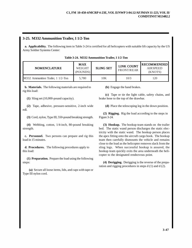
C1, FM 10-450-4/MCRP 4-23E, VOL II/NWP 3-04.12/AFJMAN 11-223, VOL II/COMDTINST M13482.2
3-47
3-25. M332 Ammunition Trailer, 1 1/2-Ton
a. Applicability. The following item in Table 3-24 is certified for all helicopters with suitable lift capacity by the USArmy Soldier Systems Center:
Table 3-24. M332 Ammunition Trailer, 1 1/2-Ton
ERUTALCNEMON ERUTALCNEMON ERUTALCNEMON ERUTALCNEMON ERUTALCNEMONXAM XAM XAM XAM XAM
THGIEW)SDNUOP(
TESGNILS TESGNILS TESGNILS TESGNILS TESGNILSTNUOCKNIL TNUOCKNIL TNUOCKNIL TNUOCKNIL TNUOCKNILRAER/TNORF
DEDNEMMOCER DEDNEMMOCER DEDNEMMOCER DEDNEMMOCER DEDNEMMOCERDEEPSRIA)STONK(
noT-2/11,reliarTnoitinummA233M 087,5 K01 3/01 021
b. Materials. The following materials are required torig this load:
(1) Sling set (10,000-pound capacity).
(2) Tape, adhesive, pressure-sensitive, 2-inch wideroll.
(3) Cord, nylon, Type III, 550-pound breaking strength.
(4) Webbing, cotton, 1/4-inch, 80-pound breakingstrength.
c. Personnel. Two persons can prepare and rig thisload in 15 minutes.
d. Procedures. The following procedures apply tothis load:
(1) Preparation. Prepare the load using the followingsteps:
(a) Secure all loose items, lids, and caps with tape orType III nylon cord.
(b) Engage the hand brakes.
(c) Tape or tie the light cable, safety chains, andbrake hose to the top of the drawbar.
(d) Place the telescoping leg in the down position.
(2) Rigging. Rig the load according to the steps inFigure 3-24.
(3) Hookup. The hookup team stands on the trailerbed. The static wand person discharges the static elec-tricity with the static wand. The hookup person placesthe apex fitting onto the aircraft cargo hook. The hookupteam then carefully dismounts the vehicle and remainsclose to the load as the helicopter removes slack from thesling legs. When successful hookup is assured, thehookup team quickly exits the area underneath the heli-copter to the designated rendezvous point.
(4) Derigging. Derigging is the reverse of the prepa-ration and rigging procedures in steps d (1) and d (2).
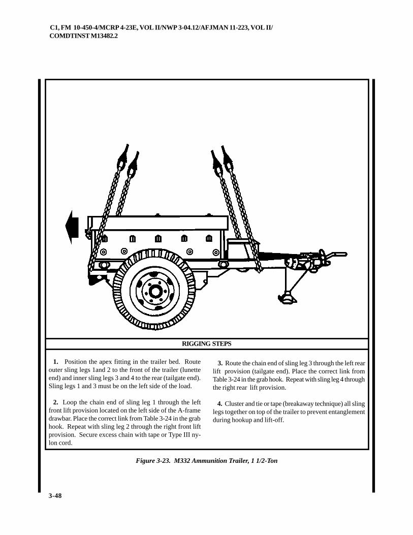
C1, FM 10-450-4/MCRP 4-23E, VOL II/NWP 3-04.12/AFJMAN 11-223, VOL II/COMDTINST M13482.2
3-48
Figure 3-23. M332 Ammunition Trailer, 1 1/2-Ton
RIGGING STEPS
1. Position the apex fitting in the trailer bed. Routeouter sling legs 1and 2 to the front of the trailer (lunetteend) and inner sling legs 3 and 4 to the rear (tailgate end).Sling legs 1 and 3 must be on the left side of the load.
2. Loop the chain end of sling leg 1 through the leftfront lift provision located on the left side of the A-framedrawbar. Place the correct link from Table 3-24 in the grabhook. Repeat with sling leg 2 through the right front liftprovision. Secure excess chain with tape or Type III ny-lon cord.
3. Route the chain end of sling leg 3 through the left rearlift provision (tailgate end). Place the correct link fromTable 3-24 in the grab hook. Repeat with sling leg 4 throughthe right rear lift provision.
4. Cluster and tie or tape (breakaway technique) all slinglegs together on top of the trailer to prevent entanglementduring hookup and lift-off.
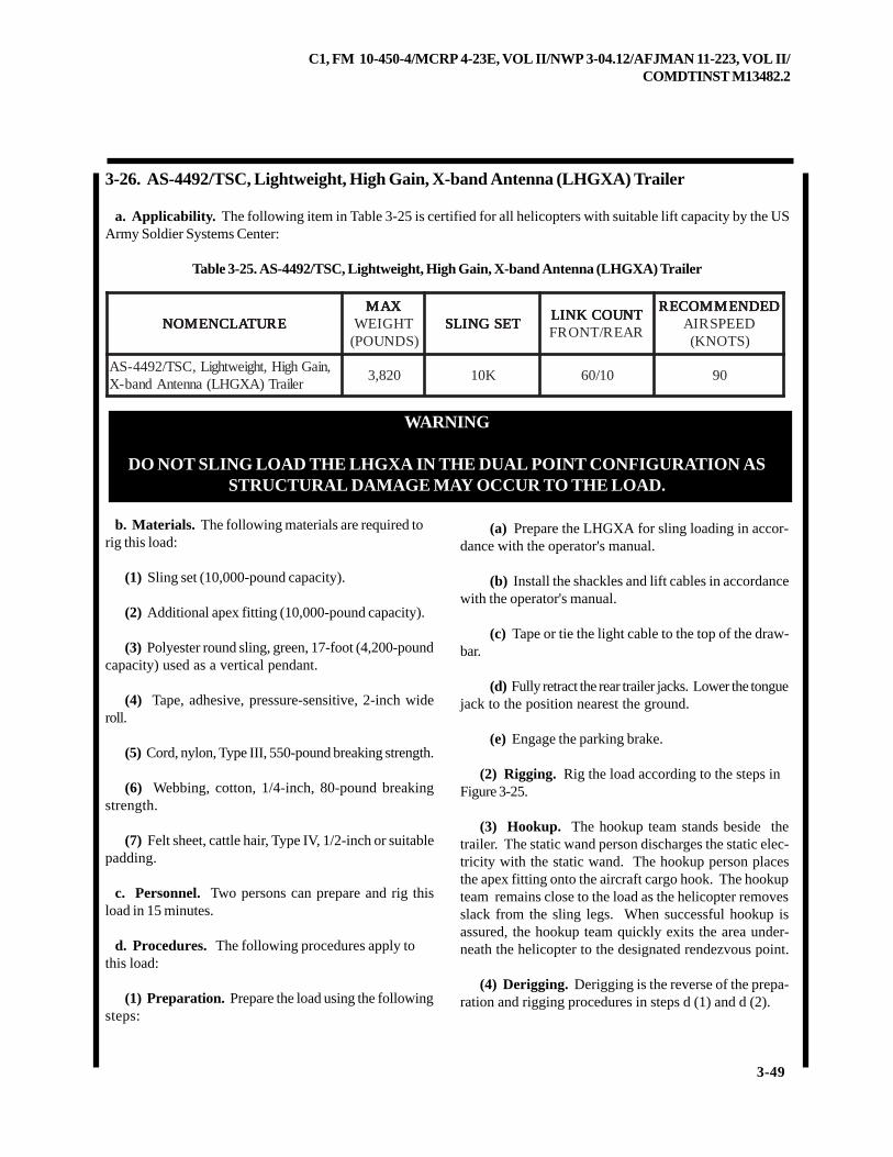
C1, FM 10-450-4/MCRP 4-23E, VOL II/NWP 3-04.12/AFJMAN 11-223, VOL II/COMDTINST M13482.2
3-49
3-26. AS-4492/TSC, Lightweight, High Gain, X-band Antenna (LHGXA) Trailer
a. Applicability. The following item in Table 3-25 is certified for all helicopters with suitable lift capacity by the USArmy Soldier Systems Center:
Table 3-25. AS-4492/TSC, Lightweight, High Gain, X-band Antenna (LHGXA) Trailer
ERUTALCNEMON ERUTALCNEMON ERUTALCNEMON ERUTALCNEMON ERUTALCNEMONXAM XAM XAM XAM XAM
THGIEW)SDNUOP(
TESGNILS TESGNILS TESGNILS TESGNILS TESGNILSTNUOCKNIL TNUOCKNIL TNUOCKNIL TNUOCKNIL TNUOCKNILRAER/TNORF
DEDNEMMOCER DEDNEMMOCER DEDNEMMOCER DEDNEMMOCER DEDNEMMOCERDEEPSRIA)STONK(
,niaGhgiH,thgiewthgiL,CST/2944-SAreliarT)AXGHL(annetnAdnab-X
028,3 K01 01/06 09
WARNING
DO NOT SLING LOAD THE LHGXA IN THE DUAL POINT CONFIGURATION ASSTRUCTURAL DAMAGE MAY OCCUR TO THE LOAD.
b. Materials. The following materials are required torig this load:
(1) Sling set (10,000-pound capacity).
(2) Additional apex fitting (10,000-pound capacity).
(3) Polyester round sling, green, 17-foot (4,200-poundcapacity) used as a vertical pendant.
(4) Tape, adhesive, pressure-sensitive, 2-inch wideroll.
(5) Cord, nylon, Type III, 550-pound breaking strength.
(6) Webbing, cotton, 1/4-inch, 80-pound breakingstrength.
(7) Felt sheet, cattle hair, Type IV, 1/2-inch or suitablepadding.
c. Personnel. Two persons can prepare and rig thisload in 15 minutes.
d. Procedures. The following procedures apply tothis load:
(1) Preparation. Prepare the load using the followingsteps:
(a) Prepare the LHGXA for sling loading in accor-dance with the operator's manual.
(b) Install the shackles and lift cables in accordancewith the operator's manual.
(c) Tape or tie the light cable to the top of the draw-bar.
(d) Fully retract the rear trailer jacks. Lower the tonguejack to the position nearest the ground.
(e) Engage the parking brake.
(2) Rigging. Rig the load according to the steps inFigure 3-25.
(3) Hookup. The hookup team stands beside thetrailer. The static wand person discharges the static elec-tricity with the static wand. The hookup person placesthe apex fitting onto the aircraft cargo hook. The hookupteam remains close to the load as the helicopter removesslack from the sling legs. When successful hookup isassured, the hookup team quickly exits the area under-neath the helicopter to the designated rendezvous point.
(4) Derigging. Derigging is the reverse of the prepa-ration and rigging procedures in steps d (1) and d (2).
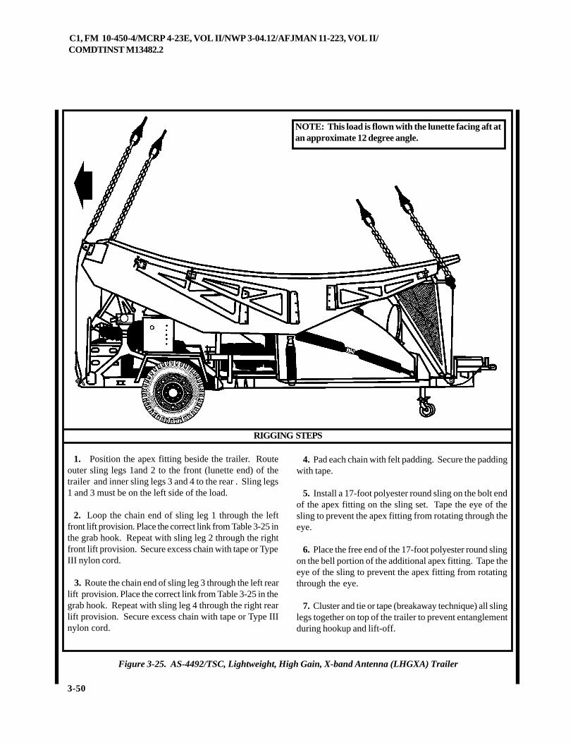
C1, FM 10-450-4/MCRP 4-23E, VOL II/NWP 3-04.12/AFJMAN 11-223, VOL II/COMDTINST M13482.2
3-50
Figure 3-25. AS-4492/TSC, Lightweight, High Gain, X-band Antenna (LHGXA) Trailer
RIGGING STEPS
1. Position the apex fitting beside the trailer. Routeouter sling legs 1and 2 to the front (lunette end) of thetrailer and inner sling legs 3 and 4 to the rear . Sling legs1 and 3 must be on the left side of the load.
2. Loop the chain end of sling leg 1 through the leftfront lift provision. Place the correct link from Table 3-25 inthe grab hook. Repeat with sling leg 2 through the rightfront lift provision. Secure excess chain with tape or TypeIII nylon cord.
3. Route the chain end of sling leg 3 through the left rearlift provision. Place the correct link from Table 3-25 in thegrab hook. Repeat with sling leg 4 through the right rearlift provision. Secure excess chain with tape or Type IIInylon cord.
4. Pad each chain with felt padding. Secure the paddingwith tape.
5. Install a 17-foot polyester round sling on the bolt endof the apex fitting on the sling set. Tape the eye of thesling to prevent the apex fitting from rotating through theeye.
6. Place the free end of the 17-foot polyester round slingon the bell portion of the additional apex fitting. Tape theeye of the sling to prevent the apex fitting from rotatingthrough the eye.
7. Cluster and tie or tape (breakaway technique) all slinglegs together on top of the trailer to prevent entanglementduring hookup and lift-off.
NOTE: This load is flown with the lunette facing aft atan approximate 12 degree angle.
C1, FM 10-450-4/MCRP 4-23E, VOL II/NWP 3-04.12/AFJMAN 11-223, VOL II/COMDTINST M13482.2
3-51
3-27. XM1112 400 Gallon Water Trailer
a. Applicability. The following item in Table 3-26 is certified for all helicopters with suitable lift capacity by theUS Army Soldier Systems Center:
Table 3-26. XM1112 400 Gallon Water Trailer
ERUTALCNEMON ERUTALCNEMON ERUTALCNEMON ERUTALCNEMON ERUTALCNEMONXAM XAM XAM XAM XAM
THGIEW)SDNUOP(
TESGNILS TESGNILS TESGNILS TESGNILS TESGNILSTNUOCKNIL TNUOCKNIL TNUOCKNIL TNUOCKNIL TNUOCKNILRAER/TNORF
DEDNEMMOCER DEDNEMMOCER DEDNEMMOCER DEDNEMMOCER DEDNEMMOCERDEEPSRIA)STONK(
,reliarTretaWnollaG0042111MXytpmE
068,3 K01 3/3 08
CAUTIONThis load is certified only when empty. Do not liftthe trailer loaded.
b. Materials. The following materials are requiredto rig this load:
(1) Sling set (10,000-pound capacity).
(2) Tape, adhesive, pressure-sensitive, 2-inch wideroll.
(3) Cord, nylon, Type III, 550-pound breakingstrength.
(4) Webbing, cotton, 1/4-inch, 80-pound breakingstrength.
(5) Felt sheet, cattle hair, Type IV, 1/2-inch or suit-able padding.
c. Personnel. Two persons can prepare and rig thisload in 10 minutes.
d. Procedures. The following procedures apply tothis load:
(1) Preparation. Prepare the load using the fol-lowing steps:
(a) Secure all loose chains, hoses, and cables tothe trailer drawbar with tape or Type III nylon cord.
(b) Ensure the tongue wheel is in the down andlocked position.
(c) Close and secure the tank lid.
(d) Engage the parking brake.
(2) Rigging. Rig the load according to the stepsin Figure 3-26.
(3) Hookup. The hookup team stands on the trailerfenders or the front of the trailer. The static wand per-son discharges the static electricity with the static wand.The hookup person places the apex fitting onto the air-craft cargo hook. The hookup team then carefully dis-mounts the trailer and remains close to the load as thehelicopter removes slack from the sling legs. When suc-cessful hookup is assured, the hookup team quickly ex-its the area underneath the helicopter to the designatedrendezvous point.
(4) Derigging. Derigging is the reverse of the prepa-ration and rigging procedures in steps d (1) and d (2).
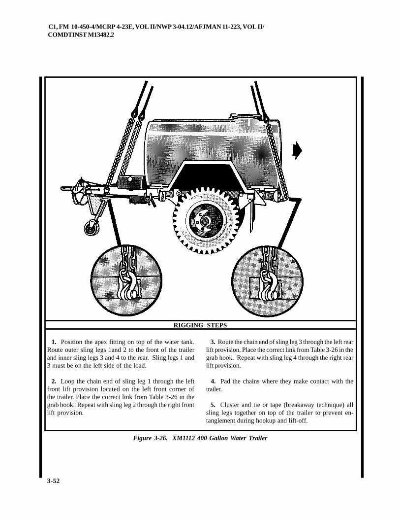
C1, FM 10-450-4/MCRP 4-23E, VOL II/NWP 3-04.12/AFJMAN 11-223, VOL II/COMDTINST M13482.2
3-52
Figure 3-26. XM1112 400 Gallon Water Trailer
RIGGING STEPS
1. Position the apex fitting on top of the water tank.Route outer sling legs 1and 2 to the front of the trailerand inner sling legs 3 and 4 to the rear. Sling legs 1 and3 must be on the left side of the load.
2. Loop the chain end of sling leg 1 through the leftfront lift provision located on the left front corner ofthe trailer. Place the correct link from Table 3-26 in thegrab hook. Repeat with sling leg 2 through the right frontlift provision.
3. Route the chain end of sling leg 3 through the left rearlift provision. Place the correct link from Table 3-26 in thegrab hook. Repeat with sling leg 4 through the right rearlift provision.
4. Pad the chains where they make contact with thetrailer.
5. Cluster and tie or tape (breakaway technique) allsling legs together on top of the trailer to prevent en-tanglement during hookup and lift-off.
C1, FM 10-450-4/MCRP 4-23E, VOL II/NWP 3-04.12/AFJMAN 11-223, VOL II/COMDTINST M13482.2
5-1
CHAPTER 5
CERTIFIED SINGLE-POINT RIGGING PROCEDURES FOR TRUCK AND TOWEDCOMBINATIONS
5-1. INTRODUCTION
This chapter contains rigging procedures for single-pointtruck and towed combination loads that have been certi-fied for sling load. Each rigging procedure is found in aparagraph that includes a description of the load, materi-als required for rigging, and steps to complete the proce-
5-2. M973/M973E1/M1065/M1066 Small Unit Support Vehicle (SUSV)
a. Applicability. The following items in Table 5-1 are certified for all helicopters with suitable lift capacity by the USArmy Soldier Systems Center:
Table 5-1. Small Unit Support Vehicle (SUSV)
b. Materials. The following materials are required torig this load:
(1) Sling set (25,000-pound capacity) (2 sets).
(2) Additional chain length, part number 38850-00053-102, from 25,000-pound capacity sling sets (8 each).
(3) Additional coupling links, part number 664241,from 25,000-pound capacity sling sets (8 each).
dure. An applicability paragraph is also a part of eachparagraph and identifies the certified loads. The certifiedsingle-point rigging procedures for truck and towed com-bination loads are in this section. Paragraphs 5-2 and 5-3give detailed instructions for rigging loads.
ERUTALCNEMON ERUTALCNEMON ERUTALCNEMON ERUTALCNEMON ERUTALCNEMONXAM XAM XAM XAM XAM
THGIEW)SDNUOP(
TESGNILS TESGNILS TESGNILS TESGNILS TESGNILSTNUOCKNIL TNUOCKNIL TNUOCKNIL TNUOCKNIL TNUOCKNILRAER/TNORF
DEDNEMMOCER DEDNEMMOCER DEDNEMMOCER DEDNEMMOCER DEDNEMMOCERDEEPSRIA)STONK(
dekcarT,ograC,379M083,6-tnorF006,6-raeR089,21-latoT
K52gniggiRnidetsiL
snoitcurtsnI08
dekcarT,ograC,1E379M083,6-tnorF006,6-raeR089,21-latoT
K52gniggiRnidetsiL
snoitcurtsnI08
dekcarT,tsoPdnammoC,5601M083,6-tnorF006,6-raeR089,21-latoT
K52gniggiRnidetsiL
snoitcurtsnI08
dekcarT,ecnalubmA,6601M083,6-tnorF006,6-raeR089,21-latoT
K52gniggiRnidetsiL
snoitcurtsnI08
C1, FM 10-450-4/MCRP 4-23E, VOL II/NWP 3-04.12/AFJMAN 11-223, VOL II/COMDTINST M13482.2
5-2
(4) Aerial delivery slings, Type XXVI nylon, 4 loop, 20foot length (2 each) (Used to form 40 foot vertical pen-dant) (For CH-47 use only).
(5) Apex fitting (25,000-pound capacity) (2 each) (ForCH-47 use only).
(6) Tape, adhesive, pressure-sensitive, 2-inch wideroll.
(7) Webbing, cotton, 1/4-inch, 80-pound breakingstrength.
(8) Tie-down strap, CGU/1B (as required).
(9) Cord, nylon, Type III, 550-pound breaking strength.
c. Personnel. Two persons can prepare and rig thisload in 30 minutes.
d. Procedures. The following procedures apply to thisload:
(1) Preparation. Prepare the load using the followingsteps:
(a) Secure all internal cargo and loose items withType III nylon cord or tie-down straps.
(b) Lock the articulated steering unit with the steer-ing cylinder locks.
(c) Secure all doors, windows, and roof hatches inthe closed position.
(d) Tape all lights and glass fixtures including thewindshield.
(e) Fold side mirrors inboard and tie or tape as re-quired.
(f) Tape windshield wipers to windshield.
(g) Secure all hoses and cables located between thetwo cars with tape or nylon cord to avoid entanglementwith sling legs.
(h) Screw the lifting eyes in as far as possible whileensuring that they are pointing towards the middle of eachcar. Tie diagonally opposing rings of each car together(for example, the front right ring to the left rear ring) withType III nylon cord.
(i) Place the mud flaps in the up position and tapethem in place.
(j) Ensure the fuel tank is not over 3/4 full. Inspectfuel tank cap, oil filler cap, and battery caps for properinstallation.
(2) Rigging. Rig the load according to the steps inFigure 5-1.
(3) Hookup. The helicopter lands near the vehicle.The hookup team crawls under the helicopter. The staticwand person discharges the static electricity with the staticwand. The hookup person places the apex fitting onto theaircraft cargo hook. The hookup team then moves clear ofthe helicopter but remains close to the load as the helicop-ter removes slack from the sling legs. When successfulhookup is assured, the hookup team quickly exits the areaunderneath the helicopter to the designated rendezvouspoint.
(4) Derigging. Derigging is the reverse of the prepa-ration and rigging procedures in steps d (1) and d (2).
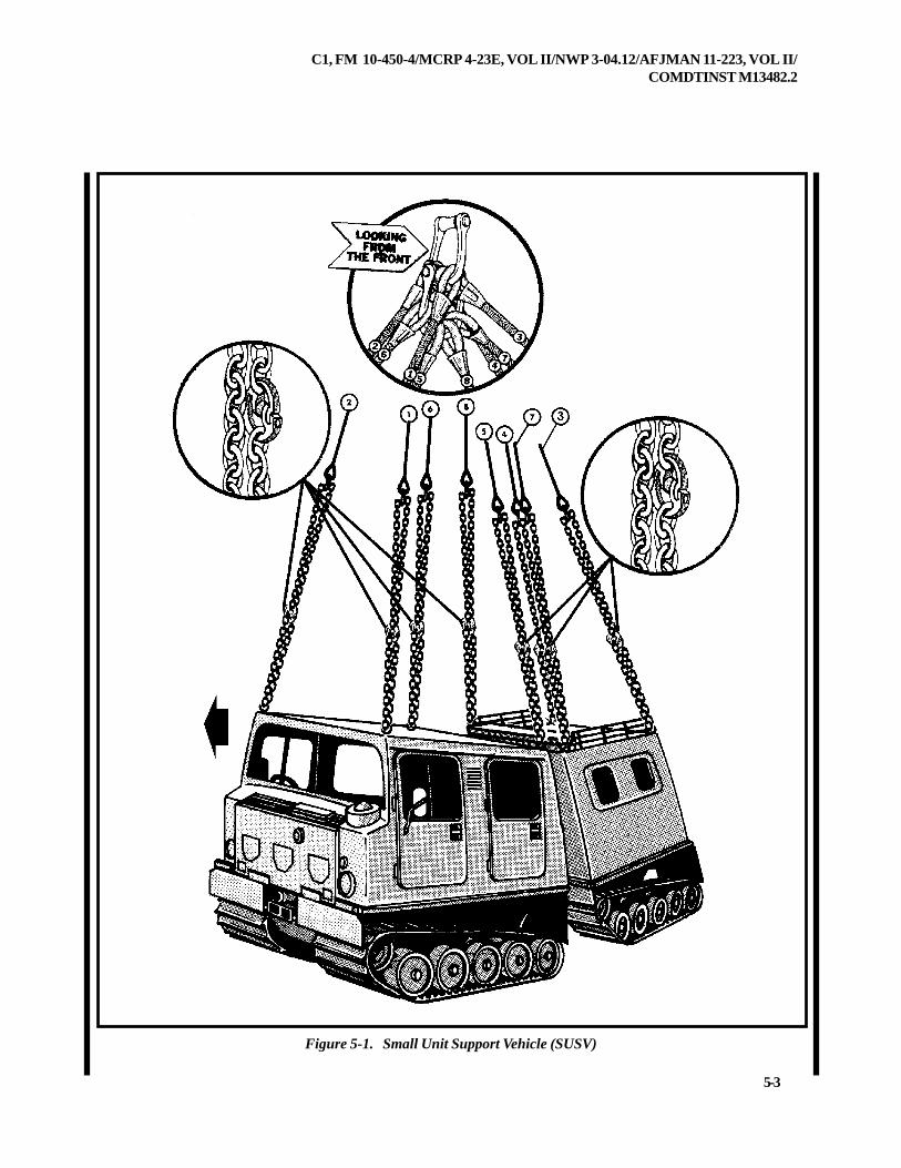
C1, FM 10-450-4/MCRP 4-23E, VOL II/NWP 3-04.12/AFJMAN 11-223, VOL II/COMDTINST M13482.2
5-3
Figure 5-1. Small Unit Support Vehicle (SUSV)
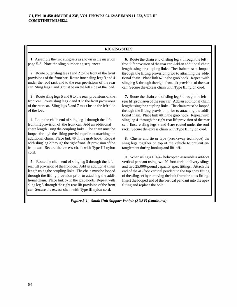
C1, FM 10-450-4/MCRP 4-23E, VOL II/NWP 3-04.12/AFJMAN 11-223, VOL II/COMDTINST M13482.2
5-4
1. Assemble the two sling sets as shown in the insert onpage 5-3. Note the sling numbering sequences.
2. Route outer sling legs 1and 2 to the front of the frontprovisions of the front car. Route inner sling legs 3 and 4under the roof rack and to the rear provisions of the rearcar. Sling legs 1 and 3 must be on the left side of the load.
3. Route sling legs 5 and 6 to the rear provisions of thefront car. Route sling legs 7 and 8 to the front provisionsof the rear car. Sling legs 5 and 7 must be on the left sideof the load.
4. Loop the chain end of sling leg 1 through the leftfront lift provision of the front car. Add an additionalchain length using the coupling links. The chain must belooped through the lifting provision prior to attaching theadditional chain. Place link 40 in the grab hook. Repeatwith sling leg 2 through the right front lift provision of thefront car. Secure the excess chain with Type III nyloncord.
5. Route the chain end of sling leg 5 through the leftrear lift provision of the front car. Add an additional chainlength using the coupling links. The chain must be loopedthrough the lifting provision prior to attaching the addi-tional chain. Place link 67 in the grab hook. Repeat withsling leg 6 through the right rear lift provision of the frontcar. Secure the excess chain with Type III nylon cord.
6. Route the chain end of sling leg 7 through the leftfront lift provision of the rear car. Add an additional chainlength using the coupling links. The chain must be loopedthrough the lifting provision prior to attaching the addi-tional chain. Place link 67 in the grab hook. Repeat withsling leg 8 through the right front lift provision of the rearcar. Secure the excess chain with Type III nylon cord.
7. Route the chain end of sling leg 3 through the leftrear lift provision of the rear car. Add an additional chainlength using the coupling links. The chain must be loopedthrough the lifting provision prior to attaching the addi-tional chain. Place link 40 in the grab hook. Repeat withsling leg 4 through the right rear lift provision of the rearcar. Ensure sling legs 3 and 4 are routed under the roofrack. Secure the excess chain with Type III nylon cord.
8. Cluster and tie or tape (breakaway technique) thesling legs together on top of the vehicle to prevent en-tanglement during hookup and lift-off.
9. When using a CH-47 helicopter, assemble a 40-footvertical pendant using two 20-foot aerial delivery slingsand two 25,000-pound capacity apex fittings. Attach theend of the 40-foot vertical pendant to the top apex fittingof the sling set by removing the bolt from the apex fitting.Insert the looped end of the vertical pendant into the apexfitting and replace the bolt.
Figure 5-1. Small Unit Support Vehicle (SUSV) (continued)
RIGGING STEPS
C1, FM 10-450-4/MCRP 4-23E, VOL II/NWP 3-04.12/AFJMAN 11-223, VOL II/COMDTINST M13482.2
5-5
5-3. M1067 Flatbed Small Unit Support Vehicle (SUSV)
a. Applicability. The following item in Table 5-2 is certified for the CH-47 HELICOPTER ONLY by the US ArmySoldier Systems Center:
Table 5-2. Flatbed Small Unit Support Vehicle (SUSV)
b. Materials. The following materials are required torig this load:
(1) Sling set (25,000-pound capacity) (2 sets).
(2) Additional chain length, part number 38850-00053-102, from 25,000-pound capacity sling sets (12 each).
(3) Additional coupling links, part number 664241,from 25,000-pound capacity sling sets (12 each).
(4) Aerial delivery slings, Type XXVI nylon, 4 loop, 20foot length (2 each) (Used to form 40 foot vertical pen-dant) (For CH-47 use only).
(5) Apex fitting (25,000-pound capacity) (2 each) (ForCH-47 use only).
(6) Tape, adhesive, pressure-sensitive, 2-inch wideroll.
(7) Webbing, cotton, 1/4-inch, 80-pound breakingstrength.
(8) Tie-down strap, CGU/1B (as required).
(9) Cord, nylon, Type III, 550-pound breaking strength.
c. Personnel. Two persons can prepare and rig thisload in 30 minutes.
d. Procedures. The following procedures apply to thisload:
(1) Preparation. Prepare the load using the following
steps:
(a) Secure all internal cargo and loose items withType III nylon cord or tie-down straps.
(b) Lock the articulated steering unit with the steer-ing cylinder locks.
(c) Secure all doors, windows, and roof hatches inthe closed position.
(d) Tape all lights and glass fixtures including thewindshield.
(e) Fold side mirrors inboard and tie or tape as re-quired.
(f) Tape windshield wipers to windshield.
(g) Secure all hoses and cables located between thetwo cars with tape or nylon cord to avoid entanglementwith sling legs.
(h) Screw the lifting eyes in as far as possible whileensuring that they are pointing towards the middle of eachcar. Tie diagonally opposing rings of each car together(for example, the front right ring to the left rear ring) withType III nylon cord.
(i) Place the mud flaps in the up position and tapethem in place.
(j) Cargo in the rear car must be loaded so that it willnot make contact with the sling legs and that it is nothigher than the sides of the rear car.
ERUTALCNEMON ERUTALCNEMON ERUTALCNEMON ERUTALCNEMON ERUTALCNEMONXAM XAM XAM XAM XAM
THGIEW)SDNUOP(
TESGNILS TESGNILS TESGNILS TESGNILS TESGNILSTNUOCKNIL TNUOCKNIL TNUOCKNIL TNUOCKNIL TNUOCKNILRAER/TNORF
DEDNEMMOCER DEDNEMMOCER DEDNEMMOCER DEDNEMMOCER DEDNEMMOCERDEEPSRIA)STONK(
dekcarT,debtalF,7601M006,6-tnorF051,7-raeR089,21-latoT
K52gniggiRnidetsiL
snoitcurtsnI07
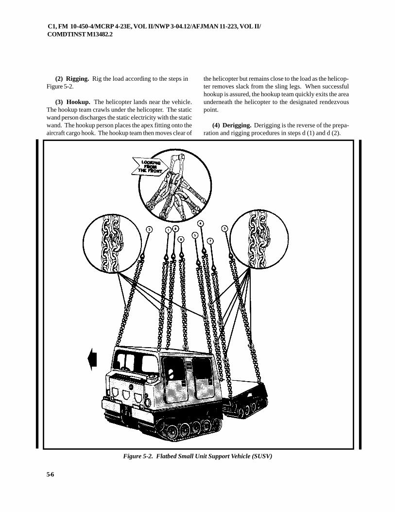
C1, FM 10-450-4/MCRP 4-23E, VOL II/NWP 3-04.12/AFJMAN 11-223, VOL II/COMDTINST M13482.2
5-6
(2) Rigging. Rig the load according to the steps inFigure 5-2.
(3) Hookup. The helicopter lands near the vehicle.The hookup team crawls under the helicopter. The staticwand person discharges the static electricity with the staticwand. The hookup person places the apex fitting onto theaircraft cargo hook. The hookup team then moves clear of
the helicopter but remains close to the load as the helicop-ter removes slack from the sling legs. When successfulhookup is assured, the hookup team quickly exits the areaunderneath the helicopter to the designated rendezvouspoint.
(4) Derigging. Derigging is the reverse of the prepa-ration and rigging procedures in steps d (1) and d (2).
Figure 5-2. Flatbed Small Unit Support Vehicle (SUSV)
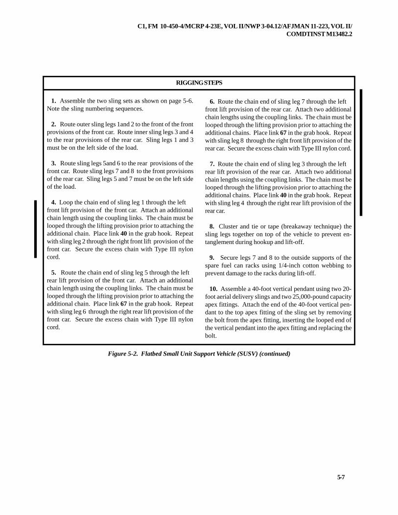
C1, FM 10-450-4/MCRP 4-23E, VOL II/NWP 3-04.12/AFJMAN 11-223, VOL II/COMDTINST M13482.2
5-7
RIGGING STEPS
1. Assemble the two sling sets as shown on page 5-6.Note the sling numbering sequences.
2. Route outer sling legs 1and 2 to the front of the frontprovisions of the front car. Route inner sling legs 3 and 4to the rear provisions of the rear car. Sling legs 1 and 3must be on the left side of the load.
3. Route sling legs 5and 6 to the rear provisions of thefront car. Route sling legs 7 and 8 to the front provisionsof the rear car. Sling legs 5 and 7 must be on the left sideof the load.
4. Loop the chain end of sling leg 1 through the leftfront lift provision of the front car. Attach an additionalchain length using the coupling links. The chain must belooped through the lifting provision prior to attaching theadditional chain. Place link 40 in the grab hook. Repeatwith sling leg 2 through the right front lift provision of thefront car. Secure the excess chain with Type III nyloncord.
5. Route the chain end of sling leg 5 through the leftrear lift provision of the front car. Attach an additionalchain length using the coupling links. The chain must belooped through the lifting provision prior to attaching theadditional chain. Place link 67 in the grab hook. Repeatwith sling leg 6 through the right rear lift provision of thefront car. Secure the excess chain with Type III nyloncord.
6. Route the chain end of sling leg 7 through the leftfront lift provision of the rear car. Attach two additionalchain lengths using the coupling links. The chain must belooped through the lifting provision prior to attaching theadditional chains. Place link 67 in the grab hook. Repeatwith sling leg 8 through the right front lift provision of therear car. Secure the excess chain with Type III nylon cord.
7. Route the chain end of sling leg 3 through the leftrear lift provision of the rear car. Attach two additionalchain lengths using the coupling links. The chain must belooped through the lifting provision prior to attaching theadditional chains. Place link 40 in the grab hook. Repeatwith sling leg 4 through the right rear lift provision of therear car.
8. Cluster and tie or tape (breakaway technique) thesling legs together on top of the vehicle to prevent en-tanglement during hookup and lift-off.
9. Secure legs 7 and 8 to the outside supports of thespare fuel can racks using 1/4-inch cotton webbing toprevent damage to the racks during lift-off.
10. Assemble a 40-foot vertical pendant using two 20-foot aerial delivery slings and two 25,000-pound capacityapex fittings. Attach the end of the 40-foot vertical pen-dant to the top apex fitting of the sling set by removingthe bolt from the apex fitting, inserting the looped end ofthe vertical pendant into the apex fitting and replacing thebolt.
Figure 5-2. Flatbed Small Unit Support Vehicle (SUSV) (continued)
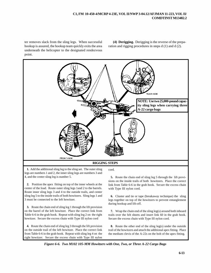
C1, FM 10-450-4/MCRP 4-23E, VOL II/NWP 3-04.12/AFJMAN 11-223, VOL II/COMDTINST M13482.2
6-13
ter removes slack from the sling legs. When successfulhookup is assured, the hookup team quickly exits the areaunderneath the helicopter to the designated rendezvouspoint.
(4) Derigging. Derigging is the reverse of the prepa-ration and rigging procedures in steps d (1) and d (2).
RIGGING STEPS
Figure 6-6. Two M102 105-MM Howitzers with One, Two, or Three A-22 Cargo Bags
1. Add the additional sling leg to the sling set. The outer slinglegs are numbers 1 and 2, the inner sling legs are numbers 3 and4, and the center sling leg is number 5.
2. Position the apex fitting on top of the inner wheels at thecenter of the load. Route outer sling legs 1and 2 to the barrels.Route inner sling legs 3 and 4 to the outside trails, and centersling leg 5 to the inside trails of both howitzers. Sling legs 1 and3 must be connected to the left howitzer.
3. Route the chain end of sling leg 1 through the lift provisionon the barrel of the left howitzer. Place the correct link fromTable 6-6 in the grab hook. Repeat with sling leg 2 on the righthowitzer. Secure the excess chain with Type III nylon cord
4. Route the chain end of sling leg 3 through the lift provisionon the outside trail of the left howitzer. Place the correct linkfrom Table 6-6 in the grab hook. Repeat with sling leg 4 on theright howitzer. Secure the excess chain with Type III nylon
cord.
5. Route the chain end of sling leg 5 through the lift provi-sions on the inside trails of both howitzers. Place the correctlink from Table 6-6 in the grab hook. Secure the excess chainwith Type III nylon cord.
6. Cluster and tie or tape (breakaway technique) the slinglegs together on top of the howitzers to prevent entanglementduring hookup and lift-off.
7. Wrap the chain end of the sling leg(s) around both inboardtrails over the felt sheets and insert link 60 in the grab hook.Secure the excess chain with Type III nylon cord.
8. Route the other end of the sling leg(s) under the outsidetrail of the howitzers and attach the additional apex fitting. Placethe medium clevis of the A-22s on the bolt of the apex fitting.
NOTE: Use two 25,000-pound capac-ity sling legs when carrying threeA-22 cargo bags
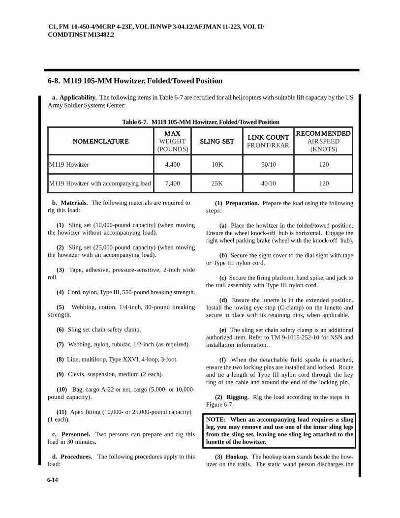
C1, FM 10-450-4/MCRP 4-23E, VOL II/NWP 3-04.12/AFJMAN 11-223, VOL II/COMDTINST M13482.2
6-14
6-8. M119 105-MM Howitzer, Folded/Towed Position
a. Applicability. The following items in Table 6-7 are certified for all helicopters with suitable lift capacity by the USArmy Soldier Systems Center:
Table 6-7. M119 105-MM Howitzer, Folded/Towed Position
b. Materials. The following materials are required torig this load:
(1) Sling set (10,000-pound capacity) (when movingthe howitzer without accompanying load).
(2) Sling set (25,000-pound capacity) (when movingthe howitzer with an accompanying load).
(3) Tape, adhesive, pressure-sensitive, 2-inch wideroll.
(4) Cord, nylon, Type III, 550-pound breaking strength.
(5) Webbing, cotton, 1/4-inch, 80-pound breakingstrength.
(6) Sling set chain safety clamp.
(7) Webbing, nylon, tubular, 1/2-inch (as required).
(8) Line, multiloop, Type XXVI, 4-loop, 3-foot.
(9) Clevis, suspension, medium (2 each).
(10) Bag, cargo A-22 or net, cargo (5,000- or 10,000-pound capacity).
(11) Apex fitting (10,000- or 25,000-pound capacity)(1 each).
c. Personnel. Two persons can prepare and rig thisload in 30 minutes.
d. Procedures. The following procedures apply to thisload:
(1) Preparation. Prepare the load using the followingsteps:
(a) Place the howitzer in the folded/towed position.Ensure the wheel knock-off hub is horizontal. Engage theright wheel parking brake (wheel with the knock-off hub).
(b) Secure the sight cover to the dial sight with tapeor Type III nylon cord.
(c) Secure the firing platform, hand spike, and jack tothe trail assembly with Type III nylon cord.
(d) Ensure the lunette is in the extended position.Install the towing eye stop (C-clamp) on the lunette andsecure in place with its retaining pins, when applicable.
(e) The sling set chain safety clamp is an additionalauthorized item. Refer to TM 9-1015-252-10 for NSN andinstallation information.
(f) When the detachable field spade is attached,ensure the two locking pins are installed and locked. Routeand tie a length of Type III nylon cord through the keyring of the cable and around the end of the locking pin.
(2) Rigging. Rig the load according to the steps inFigure 6-7.
NOTE: When an accompanying load requires a slingleg, you may remove and use one of the inner sling legsfrom the sling set, leaving one sling leg attached to thelunette of the howitzer.
(3) Hookup. The hookup team stands beside the how-itzer on the trails. The static wand person discharges the
ERUTALCNEMON ERUTALCNEMON ERUTALCNEMON ERUTALCNEMON ERUTALCNEMONXAM XAM XAM XAM XAM
THGIEW)SDNUOP(
TESGNILS TESGNILS TESGNILS TESGNILS TESGNILSTNUOCKNIL TNUOCKNIL TNUOCKNIL TNUOCKNIL TNUOCKNILRAER/TNORF
DEDNEMMOCER DEDNEMMOCER DEDNEMMOCER DEDNEMMOCER DEDNEMMOCERDEEPSRIA)STONK(
reztiwoH911M 004,4 K01 01/05 021
daolgniynapmoccahtiwreztiwoH911M 004,7 K52 01/04 021
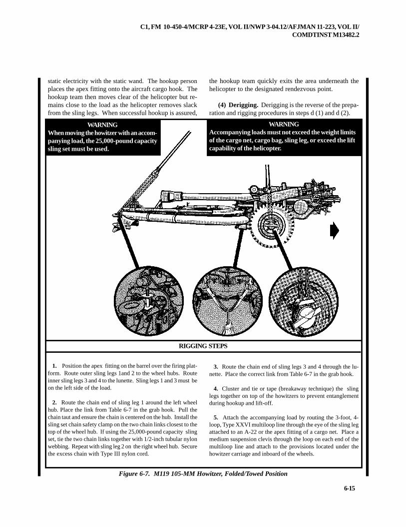
C1, FM 10-450-4/MCRP 4-23E, VOL II/NWP 3-04.12/AFJMAN 11-223, VOL II/COMDTINST M13482.2
6-15
Figure 6-7. M119 105-MM Howitzer, Folded/Towed Position
1. Position the apex fitting on the barrel over the firing plat-form. Route outer sling legs 1and 2 to the wheel hubs. Routeinner sling legs 3 and 4 to the lunette. Sling legs 1 and 3 must beon the left side of the load.
2. Route the chain end of sling leg 1 around the left wheelhub. Place the link from Table 6-7 in the grab hook. Pull thechain taut and ensure the chain is centered on the hub. Install thesling set chain safety clamp on the two chain links closest to thetop of the wheel hub. If using the 25,000-pound capacity slingset, tie the two chain links together with 1/2-inch tubular nylonwebbing. Repeat with sling leg 2 on the right wheel hub. Securethe excess chain with Type III nylon cord.
3. Route the chain end of sling legs 3 and 4 through the lu-nette. Place the correct link from Table 6-7 in the grab hook.
4. Cluster and tie or tape (breakaway technique) the slinglegs together on top of the howitzers to prevent entanglementduring hookup and lift-off.
5. Attach the accompanying load by routing the 3-foot, 4-loop, Type XXVI multiloop line through the eye of the sling legattached to an A-22 or the apex fitting of a cargo net. Place amedium suspension clevis through the loop on each end of themultiloop line and attach to the provisions located under thehowitzer carriage and inboard of the wheels.
RIGGING STEPS
static electricity with the static wand. The hookup personplaces the apex fitting onto the aircraft cargo hook. Thehookup team then moves clear of the helicopter but re-mains close to the load as the helicopter removes slackfrom the sling legs. When successful hookup is assured,
the hookup team quickly exits the area underneath thehelicopter to the designated rendezvous point.
(4) Derigging. Derigging is the reverse of the prepa-ration and rigging procedures in steps d (1) and d (2).
WARNINGWhen moving the howitzer with an accom-panying load, the 25,000-pound capacitysling set must be used.
WARNINGAccompanying loads must not exceed the weight limitsof the cargo net, cargo bag, sling leg, or exceed the liftcapability of the helicopter.
C1, FM 10-450-4/MCRP 4-23E, VOL II/NWP 3-04.12/AFJMAN 11-223, VOL II/COMDTINST M13482.2
6-16
6-9. M119 105-MM Howitzer, Forward/Firing Position
a. Applicability. The following items in Table 6-8 are certified for all helicopters with suitable lift capacity by the USArmy Soldier Systems Center:
Table 6-8. M119 105-MM Howitzer, Forward/Firing Position
(13) Coupling link, part number 664241, from a 25,000-pound capacity sling set (1 each) (for accompanying load).
(14) Strap, cargo, tiedown, CGU-1/B (as required).
c. Personnel. Two persons can prepare and rig thisload in 30 minutes.
d. Procedures. The following procedures apply to thisload:
(1) Preparation. Prepare the load using the followingsteps:
(a) Place the howitzer in the forward/firing position.If the firing platform is to be carried in the down position,follow these steps:
1 Mark the wheel hubs at the center of gravity(CG) with tape. The CG is located 6-inches behind (to-wards the lunette) the center of the hub.
2 Mark the center of the firing platform with tape.Roll the howitzer onto the firing platform aligning the tapestrips. The wheel knock-off hub must be horizontal. En-gage both parking brakes.
3 Connect the firing platform to the weapon andadd an additional CGU-1/B tiedown strap.
(b) When the firing platform is carried on top of thetrails ensure the wheel knock-off hub is horizontal. En-gage the right wheel parking brakes.
(c) Secure the sight cover to the dial sight with tape
b. Materials. The following materials are required torig this load:
(1) Sling set (10,000-pound capacity) (when movingthe howitzer without accompanying load).
(2) Sling set (25,000-pound capacity) (when movingthe howitzer with an accompanying load).
(3) Reach Pendant (11,000 or 25,000-pound capacity).
(4) Tape, adhesive, pressure-sensitive, 2-inch wideroll.
(5) Cord, nylon, Type III, 550-pound breaking strength.
(6) Webbing, cotton, 1/4-inch, 80-pound breakingstrength.
(7) Sling set chain safety clamp.
(8) Webbing, nylon, tubular, 1/2-inch (as required).
(9) Line, multiloop, Type XXVI, 4-loop, 3-foot (foraccompanying load).
(10) Clevis, suspension, medium (2 each) (for accom-panying load).
(11) Bag, cargo A-22 or net, cargo (5,000- or 10,000-pound capacity).
(12) Chain length, part number 38850-00053-102, froma 25,000-pound capacity sling set (1 each) (for accompa-nying load).
ERUTALCNEMON ERUTALCNEMON ERUTALCNEMON ERUTALCNEMON ERUTALCNEMONXAM XAM XAM XAM XAM
THGIEW)SDNUOP(
TESGNILS TESGNILS TESGNILS TESGNILS TESGNILSTNUOCKNIL TNUOCKNIL TNUOCKNIL TNUOCKNIL TNUOCKNILRAER/TNORF
DEDNEMMOCER DEDNEMMOCER DEDNEMMOCER DEDNEMMOCER DEDNEMMOCERDEEPSRIA)STONK(
reztiwoH911M 004,4 K01gniggirnidetsiL
spets011
daolgniynapmoccahtiwreztiwoH911M 004,7 K52gniggirnidetsiL
spets011
C1, FM 10-450-4/MCRP 4-23E, VOL II/NWP 3-04.12/AFJMAN 11-223, VOL II/COMDTINST M13482.2
6-17
or Type III nylon cord.
(d) Secure the firing platform (if carried), hand spike,and jack to the trail assembly with Type III nylon cord.
(e) Ensure the lunette is in the extended position.Install the towing eye stop (C-clamp) on the lunette andsecure in place with its retaining pins, when applicable.
(f) The sling set chain safety clamp is an additionalauthorized item. Refer to TM 9-1015-252-10 for NSN andinstallation information.
(g) When the detachable field spade is attached tothe permanent spades, ensure the two locking pins areinstalled and locked. Route and tie a length of Type IIInylon cord through the key ring of the cable and aroundthe end of the locking pin.
(h) When moving the howitzer without an accompa-nying load, extend the chain on sling leg 3 by removingthe chain length and coupling link from sling leg 4 andattaching them to the end of the chain on sling leg 3.
(i) When moving the howitzer with an accompany-
ing load and using sling leg 4 on the accompanying load,extend the chain on sling leg 3 by adding an additionallength of chain with a coupling link from a 25,000-poundcapacity sling set.
(2) Rigging. Rig the load according to the steps inFigure 6-8.
NOTE: When an accompanying load requires a slingleg, you may remove and use one of the inner sling legsfrom the sling set, leaving one sling leg attached to thelunette of the howitzer.
(3) Hookup. The hookup team stands beside the how-itzer on the trails. The static wand person discharges thestatic electricity with the static wand. The hookup personplaces the top loop of the reach pendant onto the aircraftcargo hook. The hookup team then moves clear of thehelicopter but remains close to the load as the helicopterremoves slack from the sling legs. When successfulhookup is assured, the hookup team quickly exits the areaunderneath the helicopter to the designated rendezvouspoint.
(4) Derigging. Derigging is the reverse of the prepa-ration and rigging procedures in steps d (1) and d (2).
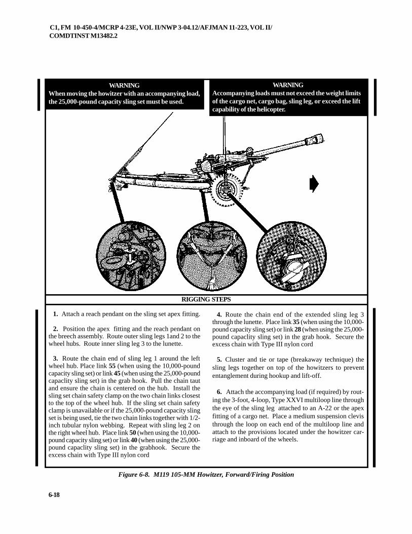
C1, FM 10-450-4/MCRP 4-23E, VOL II/NWP 3-04.12/AFJMAN 11-223, VOL II/COMDTINST M13482.2
6-18
RIGGING STEPS
1. Attach a reach pendant on the sling set apex fitting.
2. Position the apex fitting and the reach pendant onthe breech assembly. Route outer sling legs 1and 2 to thewheel hubs. Route inner sling leg 3 to the lunette.
3. Route the chain end of sling leg 1 around the leftwheel hub. Place link 55 (when using the 10,000-poundcapacity sling set) or link 45 (when using the 25,000-poundcapaclity sling set) in the grab hook. Pull the chain tautand ensure the chain is centered on the hub. Install thesling set chain safety clamp on the two chain links closestto the top of the wheel hub. If the sling set chain safetyclamp is unavailable or if the 25,000-pound capacity slingset is being used, tie the two chain links together with 1/2-inch tubular nylon webbing. Repeat with sling leg 2 onthe right wheel hub. Place link 50 (when using the 10,000-pound capacity sling set) or link 40 (when using the 25,000-pound capaclity sling set) in the grabhook. Secure theexcess chain with Type III nylon cord
4. Route the chain end of the extended sling leg 3through the lunette. Place link 35 (when using the 10,000-pound capacity sling set) or link 28 (when using the 25,000-pound capaclity sling set) in the grab hook. Secure theexcess chain with Type III nylon cord
5. Cluster and tie or tape (breakaway technique) thesling legs together on top of the howitzers to prevententanglement during hookup and lift-off.
6. Attach the accompanying load (if required) by rout-ing the 3-foot, 4-loop, Type XXVI multiloop line throughthe eye of the sling leg attached to an A-22 or the apexfitting of a cargo net. Place a medium suspension clevisthrough the loop on each end of the multiloop line andattach to the provisions located under the howitzer car-riage and inboard of the wheels.
Figure 6-8. M119 105-MM Howitzer, Forward/Firing Position
WARNINGAccompanying loads must not exceed the weight limitsof the cargo net, cargo bag, sling leg, or exceed the liftcapability of the helicopter.
WARNINGWhen moving the howitzer with an accompanying load,the 25,000-pound capacity sling set must be used.
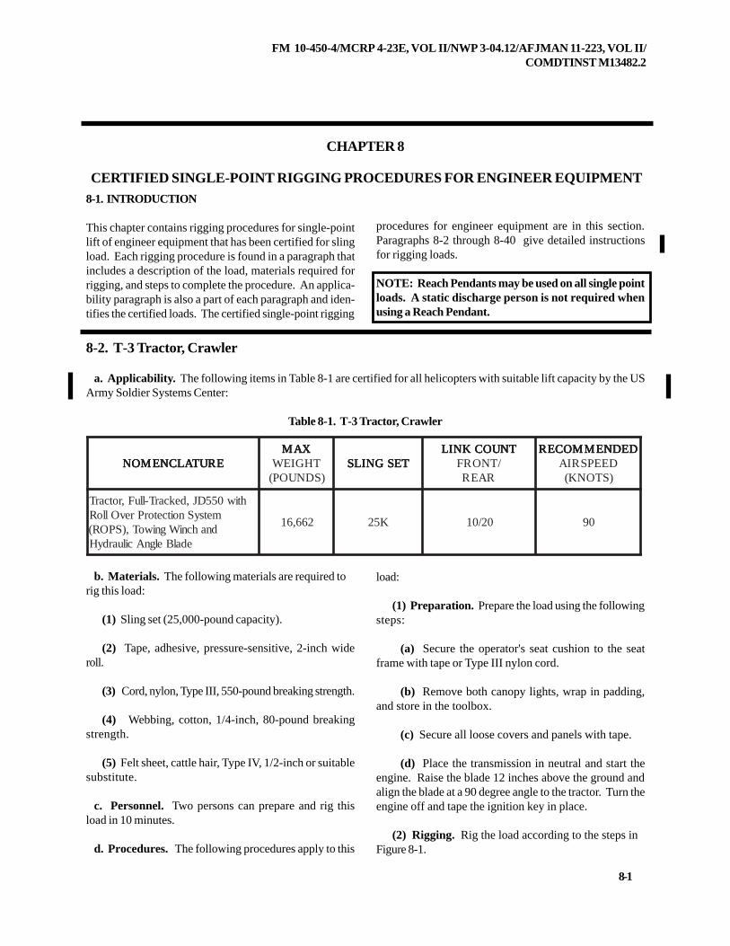
FM 10-450-4/MCRP 4-23E, VOL II/NWP 3-04.12/AFJMAN 11-223, VOL II/COMDTINST M13482.2
8-1
CHAPTER 8
CERTIFIED SINGLE-POINT RIGGING PROCEDURES FOR ENGINEER EQUIPMENT8-1. INTRODUCTION
This chapter contains rigging procedures for single-pointlift of engineer equipment that has been certified for slingload. Each rigging procedure is found in a paragraph thatincludes a description of the load, materials required forrigging, and steps to complete the procedure. An applica-bility paragraph is also a part of each paragraph and iden-tifies the certified loads. The certified single-point rigging
8-2. T-3 Tractor, Crawler
a. Applicability. The following items in Table 8-1 are certified for all helicopters with suitable lift capacity by the USArmy Soldier Systems Center:
Table 8-1. T-3 Tractor, Crawler
b. Materials. The following materials are required torig this load:
(1) Sling set (25,000-pound capacity).
(2) Tape, adhesive, pressure-sensitive, 2-inch wideroll.
(3) Cord, nylon, Type III, 550-pound breaking strength.
(4) Webbing, cotton, 1/4-inch, 80-pound breakingstrength.
(5) Felt sheet, cattle hair, Type IV, 1/2-inch or suitablesubstitute.
c. Personnel. Two persons can prepare and rig thisload in 10 minutes.
d. Procedures. The following procedures apply to this
load:
(1) Preparation. Prepare the load using the followingsteps:
(a) Secure the operator's seat cushion to the seatframe with tape or Type III nylon cord.
(b) Remove both canopy lights, wrap in padding,and store in the toolbox.
(c) Secure all loose covers and panels with tape.
(d) Place the transmission in neutral and start theengine. Raise the blade 12 inches above the ground andalign the blade at a 90 degree angle to the tractor. Turn theengine off and tape the ignition key in place.
(2) Rigging. Rig the load according to the steps inFigure 8-1.
procedures for engineer equipment are in this section.Paragraphs 8-2 through 8-40 give detailed instructionsfor rigging loads.
NOTE: Reach Pendants may be used on all single pointloads. A static discharge person is not required whenusing a Reach Pendant.
ERUTALCNEMON ERUTALCNEMON ERUTALCNEMON ERUTALCNEMON ERUTALCNEMONXAM XAM XAM XAM XAM
THGIEW)SDNUOP(
TESGNILS TESGNILS TESGNILS TESGNILS TESGNILSTNUOCKNIL TNUOCKNIL TNUOCKNIL TNUOCKNIL TNUOCKNIL
/TNORFRAER
DEDNEMMOCER DEDNEMMOCER DEDNEMMOCER DEDNEMMOCER DEDNEMMOCERDEEPSRIA)STONK(
htiw055DJ,dekcarT-lluF,rotcarTmetsySnoitcetorPrevOlloRdnahcniWgniwoT,)SPOR(
edalBelgnAciluardyH
266,61 K52 02/01 09
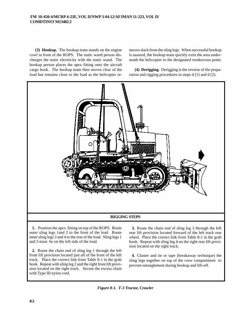
FM 10-450-4/MCRP 4-23E, VOL II/NWP 3-04.12/AFJMAN 11-223, VOL II/COMDTINST M13482.2
8-2
(3) Hookup. The hookup team stands on the enginecowl in front of the ROPS. The static wand person dis-charges the static electricity with the static wand. Thehookup person places the apex fitting onto the aircraftcargo hook. The hookup team then moves clear of theload but remains close to the load as the helicopter re-
moves slack from the sling legs. When successful hookupis assured, the hookup team quickly exits the area under-neath the helicopter to the designated rendezvous point.
(4) Derigging. Derigging is the reverse of the prepa-ration and rigging procedures in steps d (1) and d (2).
1. Position the apex fitting on top of the ROPS. Routeouter sling legs 1and 2 to the front of the load. Routeinner sling legs 3 and 4 to the rear of the load. Sling legs 1and 3 must be on the left side of the load.
2. Route the chain end of sling leg 1 through the leftfront lift provision located just aft of the front of the lefttrack. Place the correct link from Table 8-1 in the grabhook. Repeat with sling leg 2 and the right front lift provi-sion located on the right track. Secure the excess chainwith Type III nylon cord.
3. Route the chain end of sling leg 3 through the leftrear lift provision located forward of the left track rearwheel. Place the correct link from Table 8-1 in the grabhook. Repeat with sling leg 4 on the right rear lift provi-sion located on the right track.
4. Cluster and tie or tape (breakaway technique) thesling legs together on top of the crew compartment toprevent entanglement during hookup and lift-off.
Figure 8-1. T-3 Tractor, Crawler
RIGGING STEPS
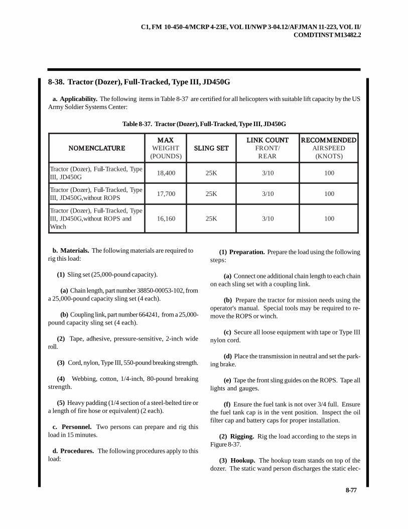
C1, FM 10-450-4/MCRP 4-23E, VOL II/NWP 3-04.12/AFJMAN 11-223, VOL II/COMDTINST M13482.2
8-77
8-38. Tractor (Dozer), Full-Tracked, Type III, JD450G
a. Applicability. The following items in Table 8-37 are certified for all helicopters with suitable lift capacity by the USArmy Soldier Systems Center:
Table 8-37. Tractor (Dozer), Full-Tracked, Type III, JD450G
(1) Preparation. Prepare the load using the followingsteps:
(a) Connect one additional chain length to each chainon each sling set with a coupling link.
(b) Prepare the tractor for mission needs using theoperator's manual. Special tools may be required to re-move the ROPS or winch.
(c) Secure all loose equipment with tape or Type IIInylon cord.
(d) Place the transmission in neutral and set the park-ing brake.
(e) Tape the front sling guides on the ROPS. Tape alllights and gauges.
(f) Ensure the fuel tank is not over 3/4 full. Ensurethe fuel tank cap is in the vent position. Inspect the oilfilter cap and battery caps for proper installation.
(2) Rigging. Rig the load according to the steps inFigure 8-37.
(3) Hookup. The hookup team stands on top of thedozer. The static wand person discharges the static elec-
b. Materials. The following materials are required torig this load:
(1) Sling set (25,000-pound capacity).
(a) Chain length, part number 38850-00053-102, froma 25,000-pound capacity sling set (4 each).
(b) Coupling link, part number 664241, from a 25,000-pound capacity sling set (4 each).
(2) Tape, adhesive, pressure-sensitive, 2-inch wideroll.
(3) Cord, nylon, Type III, 550-pound breaking strength.
(4) Webbing, cotton, 1/4-inch, 80-pound breakingstrength.
(5) Heavy padding (1/4 section of a steel-belted tire ora length of fire hose or equivalent) (2 each).
c. Personnel. Two persons can prepare and rig thisload in 15 minutes.
d. Procedures. The following procedures apply to thisload:
ERUTALCNEMON ERUTALCNEMON ERUTALCNEMON ERUTALCNEMON ERUTALCNEMONXAM XAM XAM XAM XAM
THGIEW)SDNUOP(
TESGNILS TESGNILS TESGNILS TESGNILS TESGNILSTNUOCKNIL TNUOCKNIL TNUOCKNIL TNUOCKNIL TNUOCKNIL
/TNORFRAER
DEDNEMMOCER DEDNEMMOCER DEDNEMMOCER DEDNEMMOCER DEDNEMMOCERDEEPSRIA)STONK(
epyT,dekcarT-lluF,)rezoD(rotcarTG054DJ,III
004,81 K52 01/3 001
epyT,dekcarT-lluF,)rezoD(rotcarTSPORtuohtiw,G054DJ,III
007,71 K52 01/3 001
epyT,dekcarT-lluF,)rezoD(rotcarTdnaSPORtuohtiw,G054DJ,III
hcniW061,61 K52 01/3 001
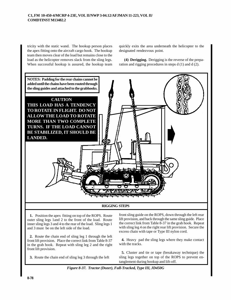
C1, FM 10-450-4/MCRP 4-23E, VOL II/NWP 3-04.12/AFJMAN 11-223, VOL II/COMDTINST M13482.2
8-78
front sling guide on the ROPS, down through the left rearlift provision, and back through the same sling guide. Placethe correct link from Table 8-37 in the grab hook. Repeatwith sling leg 4 on the right rear lift provision. Secure theexcess chain with tape or Type III nylon cord.
4. Heavy pad the sling legs where they make contactwith the tracks.
5. Cluster and tie or tape (breakaway technique) thesling legs together on top of the ROPS to prevent en-tanglement during hookup and lift-off.
1. Position the apex fitting on top of the ROPS. Routeouter sling legs 1and 2 to the front of the load. Routeinner sling legs 3 and 4 to the rear of the load. Sling legs 1and 3 must be on the left side of the load.
2. Route the chain end of sling leg 1 through the leftfront lift provision. Place the correct link from Table 8-37in the grab hook. Repeat with sling leg 2 and the rightfront lift provision.
3. Route the chain end of sling leg 3 through the left
RIGGING STEPS
Figure 8-37. Tractor (Dozer), Full-Tracked, Type III, JD450G
tricity with the static wand. The hookup person placesthe apex fitting onto the aircraft cargo hook. The hookupteam then moves clear of the load but remains close to theload as the helicopter removes slack from the sling legs.When successful hookup is assured, the hookup team
quickly exits the area underneath the helicopter to thedesignated rendezvous point.
(4) Derigging. Derigging is the reverse of the prepa-ration and rigging procedures in steps d (1) and d (2).
NOTES: Padding for the rear chains cannot beadded until the chains have been routed throughthe sling guides and attached to the grabhooks.
CAUTIONTHIS LOAD HAS A TENDENCYTO ROTATE IN FLIGHT. DO NOTALLOW THE LOAD TO ROTATEMORE THAN TWO COMPLETETURNS. IF THE LOAD CANNOTBE STABILIZED, IT SHOULD BELANDED.
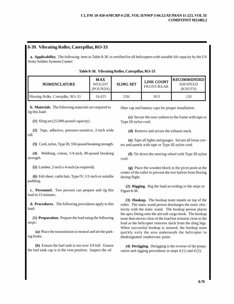
C1, FM 10-450-4/MCRP 4-23E, VOL II/NWP 3-04.12/AFJMAN 11-223, VOL II/COMDTINST M13482.2
8-79
8-39. Vibrating Roller, Caterpillar, RO-33
a. Applicability. The following item in Table 8-38 is certified for all helicopters with suitable lift capacity by the USArmy Soldier Systems Center:
Table 8-38. Vibrating Roller, Caterpillar, RO-33
ERUTALCNEMON ERUTALCNEMON ERUTALCNEMON ERUTALCNEMON ERUTALCNEMONXAM XAM XAM XAM XAM
THGIEW)SDNUOP(
TESGNILS TESGNILS TESGNILS TESGNILS TESGNILSTNUOCKNIL TNUOCKNIL TNUOCKNIL TNUOCKNIL TNUOCKNILRAER/TNORF
DEDNEMMOCER DEDNEMMOCER DEDNEMMOCER DEDNEMMOCER DEDNEMMOCERDEEPSRIA)STONK(
33-OR,rallipretaC,relloRgnitarbiV 524,61 K52 3/03 021
b. Materials. The following materials are required torig this load:
(1) Sling set (25,000-pound capacity).
(2) Tape, adhesive, pressure-sensitive, 2-inch wideroll.
(3) Cord, nylon, Type III, 550-pound breaking strength.
(4) Webbing, cotton, 1/4-inch, 80-pound breakingstrength.
(5) Lumber, 2-inch x 4-inch (as required).
(6) Felt sheet, cattle hair, Type IV, 1/2-inch or suitablepadding.
c. Personnel. Two persons can prepare and rig thisload in 15 minutes.
d. Procedures. The following procedures apply to thisload:
(1) Preparation. Prepare the load using the followingsteps:
(a) Place the transmission in neutral and set the park-ing brake.
(b) Ensure the fuel tank is not over 3/4 full. Ensurethe fuel tank cap is in the vent position. Inspect the oil
filter cap and battery caps for proper installation.
(c) Secure the seat cushion to the frame with tape orType III nylon cord.
(d) Remove and secure the exhaust stack.
(e) Tape all lights and gauges. Secure all loose cov-ers and panels with tape or Type III nylon cord.
(f) Tie down the steering wheel with Type III nyloncord.
(g) Place the wooden block in the pivot point at thecenter of the roller to prevent the two halves from flexingduring flight.
(2) Rigging. Rig the load according to the steps inFigure 8-38.
(3) Hookup. The hookup team stands on top of theroller. The static wand person discharges the static elec-tricity with the static wand. The hookup person placesthe apex fitting onto the aircraft cargo hook. The hookupteam then moves clear of the load but remains close to theload as the helicopter removes slack from the sling legs.When successful hookup is assured, the hookup teamquickly exits the area underneath the helicopter tothedesignated rendezvous point.
(4) Derigging. Derigging is the reverse of the prepa-ration and rigging procedures in steps d (1) and d (2).
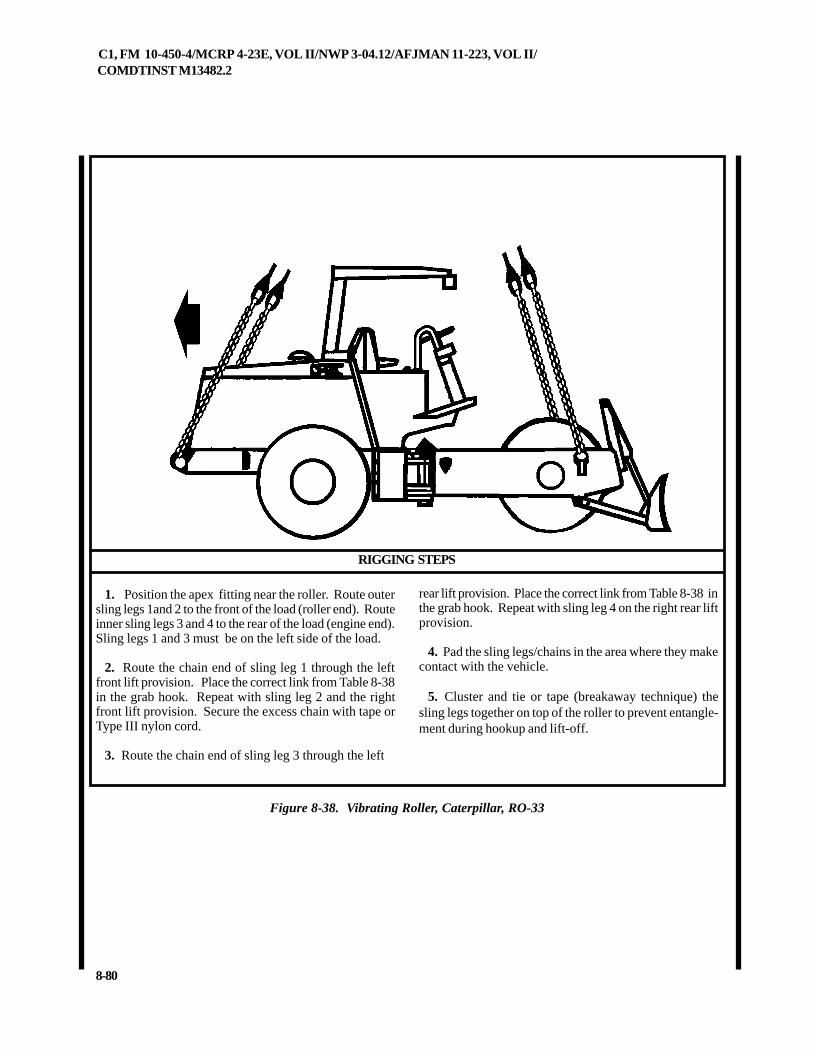
C1, FM 10-450-4/MCRP 4-23E, VOL II/NWP 3-04.12/AFJMAN 11-223, VOL II/COMDTINST M13482.2
8-80
RIGGING STEPS
Figure 8-38. Vibrating Roller, Caterpillar, RO-33
1. Position the apex fitting near the roller. Route outersling legs 1and 2 to the front of the load (roller end). Routeinner sling legs 3 and 4 to the rear of the load (engine end).Sling legs 1 and 3 must be on the left side of the load.
2. Route the chain end of sling leg 1 through the leftfront lift provision. Place the correct link from Table 8-38in the grab hook. Repeat with sling leg 2 and the rightfront lift provision. Secure the excess chain with tape orType III nylon cord.
3. Route the chain end of sling leg 3 through the left
rear lift provision. Place the correct link from Table 8-38 inthe grab hook. Repeat with sling leg 4 on the right rear liftprovision.
4. Pad the sling legs/chains in the area where they makecontact with the vehicle.
5. Cluster and tie or tape (breakaway technique) thesling legs together on top of the roller to prevent entangle-ment during hookup and lift-off.
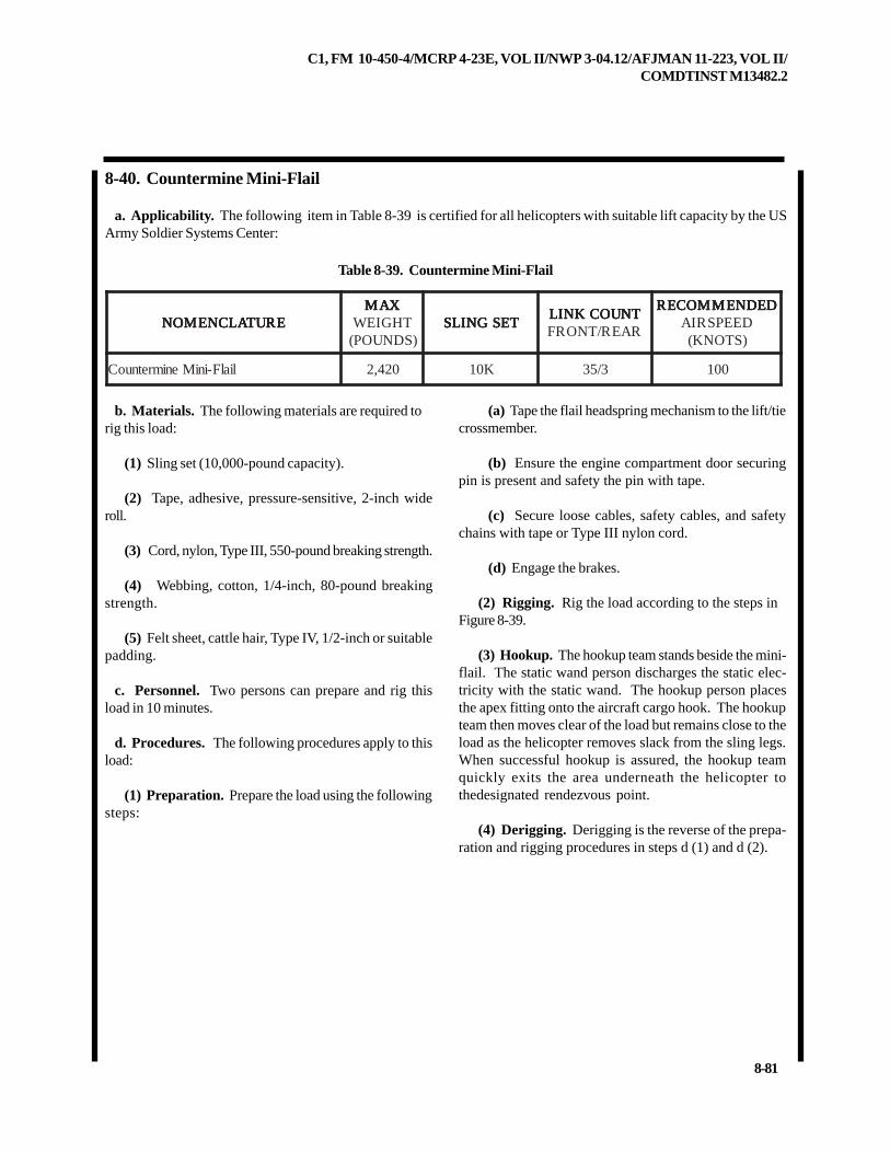
C1, FM 10-450-4/MCRP 4-23E, VOL II/NWP 3-04.12/AFJMAN 11-223, VOL II/COMDTINST M13482.2
8-81
8-40. Countermine Mini-Flail
a. Applicability. The following item in Table 8-39 is certified for all helicopters with suitable lift capacity by the USArmy Soldier Systems Center:
Table 8-39. Countermine Mini-Flail
ERUTALCNEMON ERUTALCNEMON ERUTALCNEMON ERUTALCNEMON ERUTALCNEMONXAM XAM XAM XAM XAM
THGIEW)SDNUOP(
TESGNILS TESGNILS TESGNILS TESGNILS TESGNILSTNUOCKNIL TNUOCKNIL TNUOCKNIL TNUOCKNIL TNUOCKNILRAER/TNORF
DEDNEMMOCER DEDNEMMOCER DEDNEMMOCER DEDNEMMOCER DEDNEMMOCERDEEPSRIA)STONK(
lialF-iniMenimretnuoC 024,2 K01 3/53 001
b. Materials. The following materials are required torig this load:
(1) Sling set (10,000-pound capacity).
(2) Tape, adhesive, pressure-sensitive, 2-inch wideroll.
(3) Cord, nylon, Type III, 550-pound breaking strength.
(4) Webbing, cotton, 1/4-inch, 80-pound breakingstrength.
(5) Felt sheet, cattle hair, Type IV, 1/2-inch or suitablepadding.
c. Personnel. Two persons can prepare and rig thisload in 10 minutes.
d. Procedures. The following procedures apply to thisload:
(1) Preparation. Prepare the load using the followingsteps:
(a) Tape the flail headspring mechanism to the lift/tiecrossmember.
(b) Ensure the engine compartment door securingpin is present and safety the pin with tape.
(c) Secure loose cables, safety cables, and safetychains with tape or Type III nylon cord.
(d) Engage the brakes.
(2) Rigging. Rig the load according to the steps inFigure 8-39.
(3) Hookup. The hookup team stands beside the mini-flail. The static wand person discharges the static elec-tricity with the static wand. The hookup person placesthe apex fitting onto the aircraft cargo hook. The hookupteam then moves clear of the load but remains close to theload as the helicopter removes slack from the sling legs.When successful hookup is assured, the hookup teamquickly exits the area underneath the helicopter tothedesignated rendezvous point.
(4) Derigging. Derigging is the reverse of the prepa-ration and rigging procedures in steps d (1) and d (2).
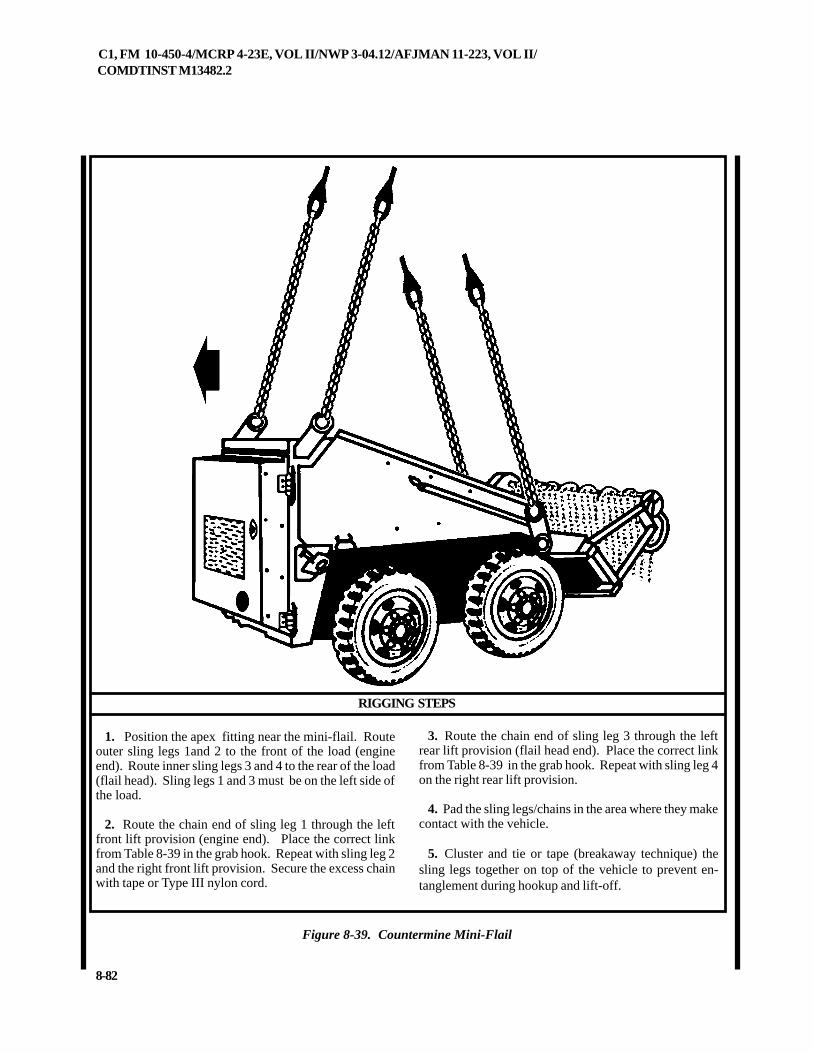
C1, FM 10-450-4/MCRP 4-23E, VOL II/NWP 3-04.12/AFJMAN 11-223, VOL II/COMDTINST M13482.2
8-82
Figure 8-39. Countermine Mini-Flail
RIGGING STEPS
1. Position the apex fitting near the mini-flail. Routeouter sling legs 1and 2 to the front of the load (engineend). Route inner sling legs 3 and 4 to the rear of the load(flail head). Sling legs 1 and 3 must be on the left side ofthe load.
2. Route the chain end of sling leg 1 through the leftfront lift provision (engine end). Place the correct linkfrom Table 8-39 in the grab hook. Repeat with sling leg 2and the right front lift provision. Secure the excess chainwith tape or Type III nylon cord.
3. Route the chain end of sling leg 3 through the leftrear lift provision (flail head end). Place the correct linkfrom Table 8-39 in the grab hook. Repeat with sling leg 4on the right rear lift provision.
4. Pad the sling legs/chains in the area where they makecontact with the vehicle.
5. Cluster and tie or tape (breakaway technique) thesling legs together on top of the vehicle to prevent en-tanglement during hookup and lift-off.
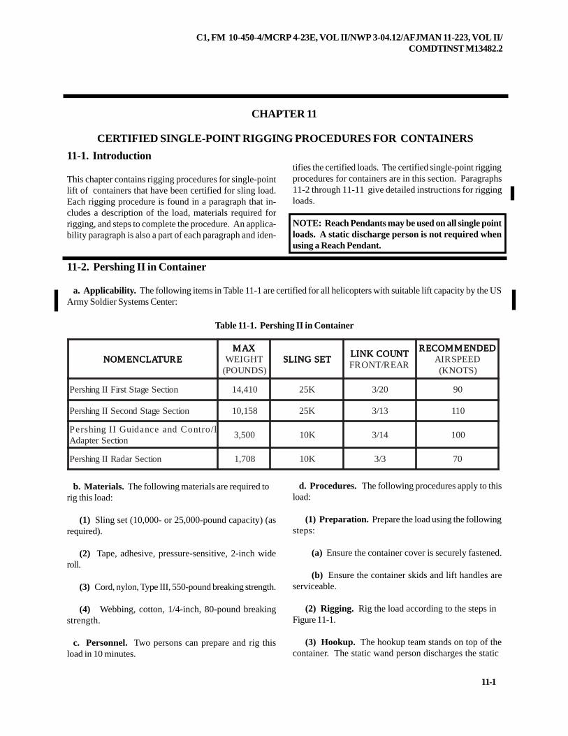
C1, FM 10-450-4/MCRP 4-23E, VOL II/NWP 3-04.12/AFJMAN 11-223, VOL II/COMDTINST M13482.2
11-1
CHAPTER 11
CERTIFIED SINGLE-POINT RIGGING PROCEDURES FOR CONTAINERS
11-1. Introduction
This chapter contains rigging procedures for single-pointlift of containers that have been certified for sling load.Each rigging procedure is found in a paragraph that in-cludes a description of the load, materials required forrigging, and steps to complete the procedure. An applica-bility paragraph is also a part of each paragraph and iden-
11-2. Pershing II in Container
a. Applicability. The following items in Table 11-1 are certified for all helicopters with suitable lift capacity by the USArmy Soldier Systems Center:
Table 11-1. Pershing II in Container
b. Materials. The following materials are required torig this load:
(1) Sling set (10,000- or 25,000-pound capacity) (asrequired).
(2) Tape, adhesive, pressure-sensitive, 2-inch wideroll.
(3) Cord, nylon, Type III, 550-pound breaking strength.
(4) Webbing, cotton, 1/4-inch, 80-pound breakingstrength.
c. Personnel. Two persons can prepare and rig thisload in 10 minutes.
d. Procedures. The following procedures apply to thisload:
(1) Preparation. Prepare the load using the followingsteps:
(a) Ensure the container cover is securely fastened.
(b) Ensure the container skids and lift handles areserviceable.
(2) Rigging. Rig the load according to the steps inFigure 11-1.
(3) Hookup. The hookup team stands on top of thecontainer. The static wand person discharges the static
tifies the certified loads. The certified single-point riggingprocedures for containers are in this section. Paragraphs11-2 through 11-11 give detailed instructions for riggingloads.
NOTE: Reach Pendants may be used on all single pointloads. A static discharge person is not required whenusing a Reach Pendant.
ERUTALCNEMON ERUTALCNEMON ERUTALCNEMON ERUTALCNEMON ERUTALCNEMONXAM XAM XAM XAM XAM
THGIEW)SDNUOP(
TESGNILS TESGNILS TESGNILS TESGNILS TESGNILSTNUOCKNIL TNUOCKNIL TNUOCKNIL TNUOCKNIL TNUOCKNILRAER/TNORF
DEDNEMMOCER DEDNEMMOCER DEDNEMMOCER DEDNEMMOCER DEDNEMMOCERDEEPSRIA)STONK(
noitceSegatStsriFIIgnihsreP 014,41 K52 02/3 09
noitceSegatSdnoceSIIgnihsreP 851,01 K52 31/3 011
l/ortnoCdnaecnadiuGIIgnihsrePnoitceSretpadA
005,3 K01 41/3 001
noitceSradaRIIgnihsreP 807,1 K01 3/3 07
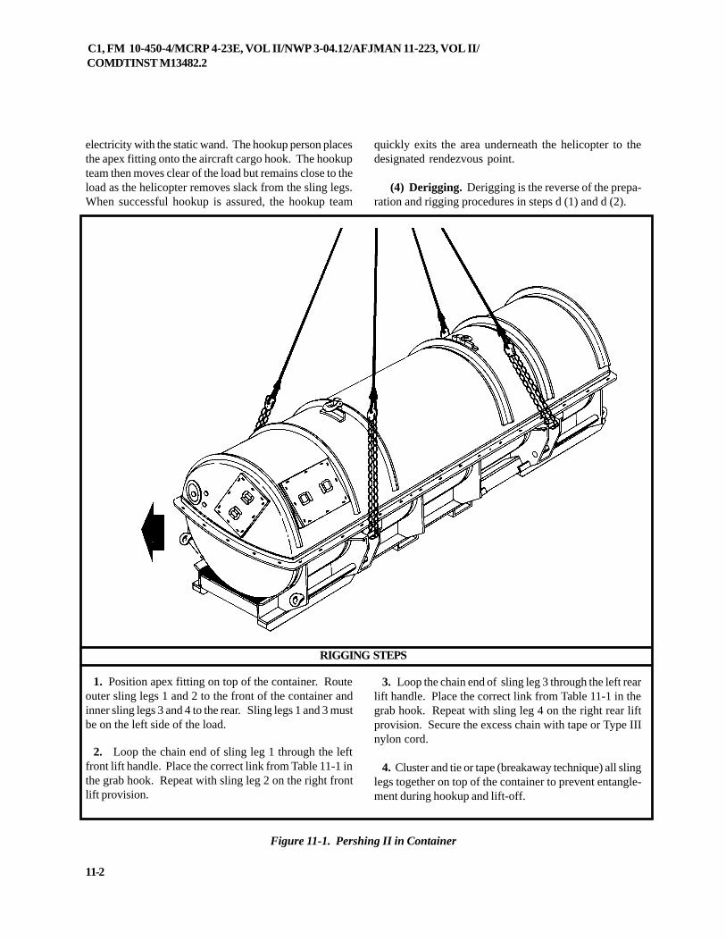
C1, FM 10-450-4/MCRP 4-23E, VOL II/NWP 3-04.12/AFJMAN 11-223, VOL II/COMDTINST M13482.2
11-2
electricity with the static wand. The hookup person placesthe apex fitting onto the aircraft cargo hook. The hookupteam then moves clear of the load but remains close to theload as the helicopter removes slack from the sling legs.When successful hookup is assured, the hookup team
quickly exits the area underneath the helicopter to thedesignated rendezvous point.
(4) Derigging. Derigging is the reverse of the prepa-ration and rigging procedures in steps d (1) and d (2).
Figure 11-1. Pershing II in Container
1. Position apex fitting on top of the container. Routeouter sling legs 1 and 2 to the front of the container andinner sling legs 3 and 4 to the rear. Sling legs 1 and 3 mustbe on the left side of the load.
2. Loop the chain end of sling leg 1 through the leftfront lift handle. Place the correct link from Table 11-1 inthe grab hook. Repeat with sling leg 2 on the right frontlift provision.
3. Loop the chain end of sling leg 3 through the left rearlift handle. Place the correct link from Table 11-1 in thegrab hook. Repeat with sling leg 4 on the right rear liftprovision. Secure the excess chain with tape or Type IIInylon cord.
4. Cluster and tie or tape (breakaway technique) all slinglegs together on top of the container to prevent entangle-ment during hookup and lift-off.
RIGGING STEPS
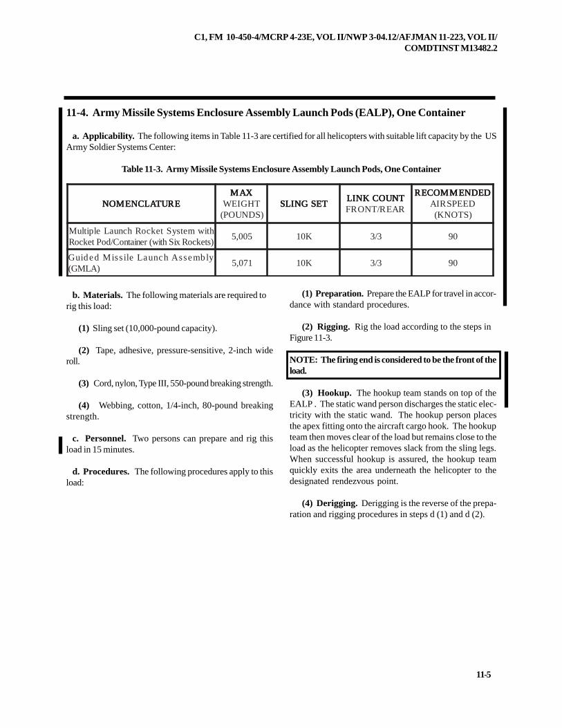
C1, FM 10-450-4/MCRP 4-23E, VOL II/NWP 3-04.12/AFJMAN 11-223, VOL II/COMDTINST M13482.2
11-5
11-4. Army Missile Systems Enclosure Assembly Launch Pods (EALP), One Container
a. Applicability. The following items in Table 11-3 are certified for all helicopters with suitable lift capacity by the USArmy Soldier Systems Center:
Table 11-3. Army Missile Systems Enclosure Assembly Launch Pods, One Container
b. Materials. The following materials are required torig this load:
(1) Sling set (10,000-pound capacity).
(2) Tape, adhesive, pressure-sensitive, 2-inch wideroll.
(3) Cord, nylon, Type III, 550-pound breaking strength.
(4) Webbing, cotton, 1/4-inch, 80-pound breakingstrength.
c. Personnel. Two persons can prepare and rig thisload in 15 minutes.
d. Procedures. The following procedures apply to thisload:
(1) Preparation. Prepare the EALP for travel in accor-dance with standard procedures.
(2) Rigging. Rig the load according to the steps inFigure 11-3.
NOTE: The firing end is considered to be the front of theload.
(3) Hookup. The hookup team stands on top of theEALP . The static wand person discharges the static elec-tricity with the static wand. The hookup person placesthe apex fitting onto the aircraft cargo hook. The hookupteam then moves clear of the load but remains close to theload as the helicopter removes slack from the sling legs.When successful hookup is assured, the hookup teamquickly exits the area underneath the helicopter to thedesignated rendezvous point.
(4) Derigging. Derigging is the reverse of the prepa-ration and rigging procedures in steps d (1) and d (2).
ERUTALCNEMON ERUTALCNEMON ERUTALCNEMON ERUTALCNEMON ERUTALCNEMONXAM XAM XAM XAM XAM
THGIEW)SDNUOP(
TESGNILS TESGNILS TESGNILS TESGNILS TESGNILSTNUOCKNIL TNUOCKNIL TNUOCKNIL TNUOCKNIL TNUOCKNILRAER/TNORF
DEDNEMMOCER DEDNEMMOCER DEDNEMMOCER DEDNEMMOCER DEDNEMMOCERDEEPSRIA)STONK(
htiwmetsyStekcoRhcnuaLelpitluM)stekcoRxiShtiw(reniatnoC/doPtekcoR
500,5 K01 3/3 09
ylbmessAhcnuaLelissiMdediuG)ALMG(
170,5 K01 3/3 09
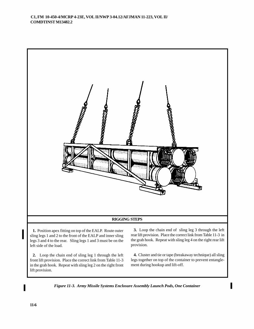
C1, FM 10-450-4/MCRP 4-23E, VOL II/NWP 3-04.12/AFJMAN 11-223, VOL II/COMDTINST M13482.2
11-6
RIGGING STEPS
3. Loop the chain end of sling leg 3 through the leftrear lift provision. Place the correct link from Table 11-3 inthe grab hook. Repeat with sling leg 4 on the right rear liftprovision.
4. Cluster and tie or tape (breakaway technique) all slinglegs together on top of the container to prevent entangle-ment during hookup and lift-off.
Figure 11-3. Army Missile Systems Enclosure Assembly Launch Pods, One Container
1. Position apex fitting on top of the EALP. Route outersling legs 1 and 2 to the front of the EALP and inner slinglegs 3 and 4 to the rear. Sling legs 1 and 3 must be on theleft side of the load.
2. Loop the chain end of sling leg 1 through the leftfront lift provision. Place the correct link from Table 11-3in the grab hook. Repeat with sling leg 2 on the right frontlift provision.
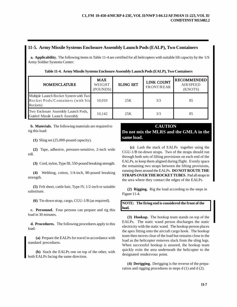
C1, FM 10-450-4/MCRP 4-23E, VOL II/NWP 3-04.12/AFJMAN 11-223, VOL II/COMDTINST M13482.2
11-7
11-5. Army Missile Systems Enclosure Assembly Launch Pods (EALP), Two Containers
a. Applicability. The following items in Table 11-4 are certified for all helicopters with suitable lift capacity by the USArmy Soldier Systems Center:
Table 11-4. Army Missile Systems Enclosure Assembly Launch Pods (EALP), Two Containers
b. Materials. The following materials are required torig this load:
(1) Sling set (25,000-pound capacity).
(2) Tape, adhesive, pressure-sensitive, 2-inch wideroll.
(3) Cord, nylon, Type III, 550-pound breaking strength.
(4) Webbing, cotton, 1/4-inch, 80-pound breakingstrength.
(5) Felt sheet, cattle hair, Type IV, 1/2-inch or suitablesubstitute.
(6) Tie-down strap, cargo, CGU-1/B (as required).
c. Personnel. Four persons can prepare and rig thisload in 30 minutes.
d. Procedures. The following procedures apply to thisload:
(a) Prepare the EALPs for travel in accordance withstandard procedures.
(b) Stack the EALPs one on top of the other, withboth EALPs facing the same direction.
CAUTIONDo not mix the MLRS and the GMLA in thesame load.
(c) Lash the stack of EALPs together using theCGU-1/B tie-down straps. Two of the straps should runthrough both sets of lifting provisions on each end of theEALPs, to keep them aligned during flight. Evenly spacethe remaining two straps between the lifting provisions,running them around the EALPs. DO NOT ROUTE THESTRAPS OVER THE ROCKET TUBES. Pad all straps inthe area where they contact the edges of the EALPs.
(2) Rigging. Rig the load according to the steps inFigure 11-4.
NOTE: The firing end is considered the front of theload.
(3) Hookup. The hookup team stands on top of theEALPs. The static wand person discharges the staticelectricity with the static wand. The hookup person placesthe apex fitting onto the aircraft cargo hook. The hookupteam then moves clear of the load but remains close to theload as the helicopter removes slack from the sling legs.When successful hookup is assured, the hookup teamquickly exits the area underneath the helicopter to thedesignated rendezvous point.
(4) Derigging. Derigging is the reverse of the prepa-ration and rigging procedures in steps d (1) and d (2).
ERUTALCNEMON ERUTALCNEMON ERUTALCNEMON ERUTALCNEMON ERUTALCNEMONXAM XAM XAM XAM XAM
THGIEW)SDNUOP(
TESGNILS TESGNILS TESGNILS TESGNILS TESGNILSTNUOCKNIL TNUOCKNIL TNUOCKNIL TNUOCKNIL TNUOCKNILRAER/TNORF
DEDNEMMOCER DEDNEMMOCER DEDNEMMOCER DEDNEMMOCER DEDNEMMOCERDEEPSRIA)STONK(
owThtiwmetsyStekcoRhcnuaLelpitluMxiShtiw(sreniatnoC/sdoPtekcoR
)stekcoR010,01 K52 3/3 58
,sdoPhcnuaLylbmessAerusolcnEowTylbmessAhcnuaLelissiMdediuG
241,01 K52 3/3 58
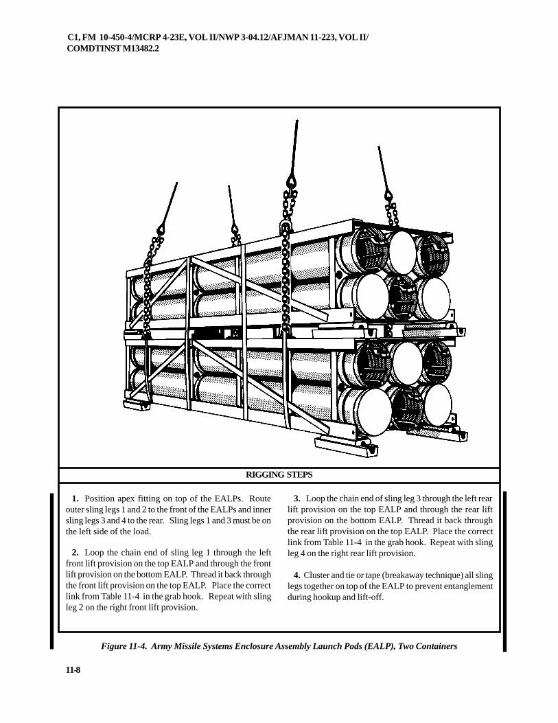
C1, FM 10-450-4/MCRP 4-23E, VOL II/NWP 3-04.12/AFJMAN 11-223, VOL II/COMDTINST M13482.2
11-8
RIGGING STEPS
Figure 11-4. Army Missile Systems Enclosure Assembly Launch Pods (EALP), Two Containers
1. Position apex fitting on top of the EALPs. Routeouter sling legs 1 and 2 to the front of the EALPs and innersling legs 3 and 4 to the rear. Sling legs 1 and 3 must be onthe left side of the load.
2. Loop the chain end of sling leg 1 through the leftfront lift provision on the top EALP and through the frontlift provision on the bottom EALP. Thread it back throughthe front lift provision on the top EALP. Place the correctlink from Table 11-4 in the grab hook. Repeat with slingleg 2 on the right front lift provision.
3. Loop the chain end of sling leg 3 through the left rearlift provision on the top EALP and through the rear liftprovision on the bottom EALP. Thread it back throughthe rear lift provision on the top EALP. Place the correctlink from Table 11-4 in the grab hook. Repeat with slingleg 4 on the right rear lift provision.
4. Cluster and tie or tape (breakaway technique) all slinglegs together on top of the EALP to prevent entanglementduring hookup and lift-off.
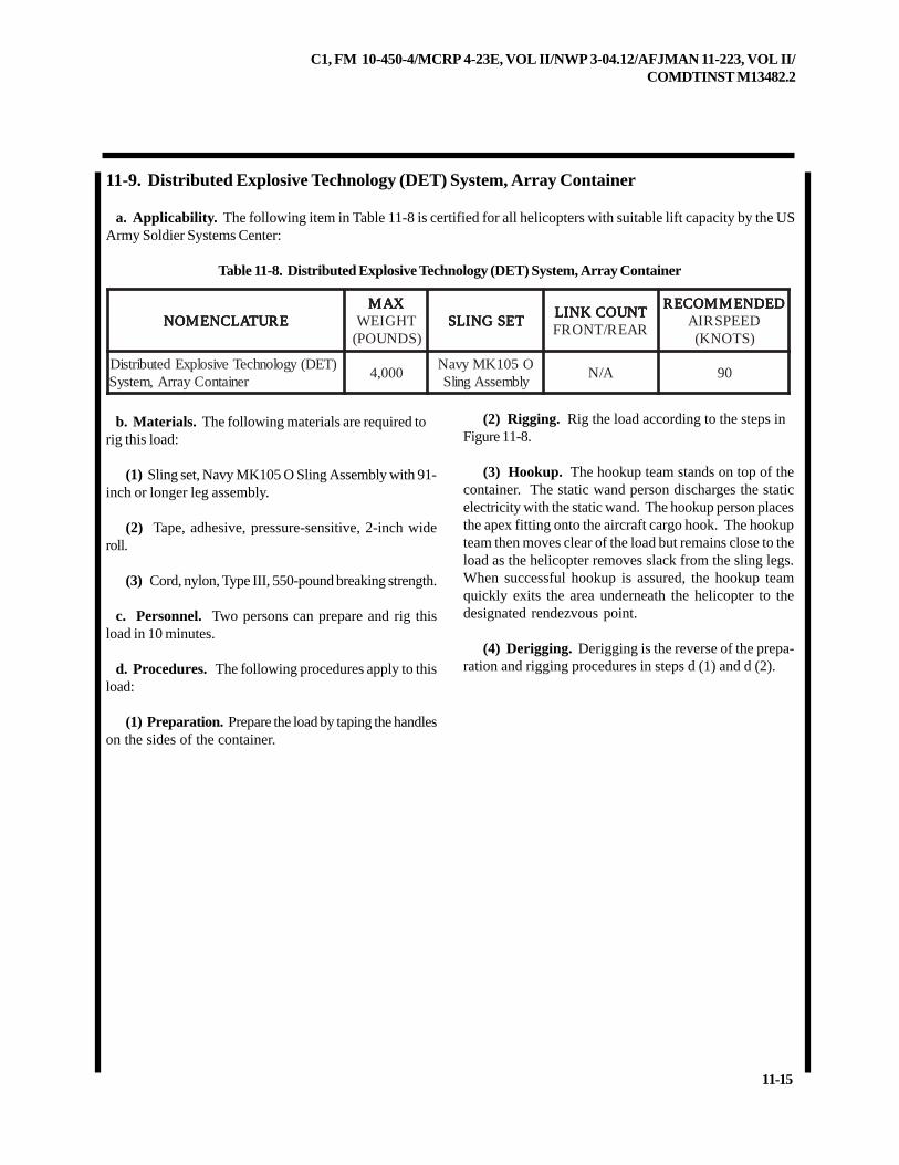
C1, FM 10-450-4/MCRP 4-23E, VOL II/NWP 3-04.12/AFJMAN 11-223, VOL II/COMDTINST M13482.2
11-15
11-9. Distributed Explosive Technology (DET) System, Array Container
a. Applicability. The following item in Table 11-8 is certified for all helicopters with suitable lift capacity by the USArmy Soldier Systems Center:
Table 11-8. Distributed Explosive Technology (DET) System, Array Container
b. Materials. The following materials are required torig this load:
(1) Sling set, Navy MK105 O Sling Assembly with 91-inch or longer leg assembly.
(2) Tape, adhesive, pressure-sensitive, 2-inch wideroll.
(3) Cord, nylon, Type III, 550-pound breaking strength.
c. Personnel. Two persons can prepare and rig thisload in 10 minutes.
d. Procedures. The following procedures apply to thisload:
(1) Preparation. Prepare the load by taping the handleson the sides of the container.
ERUTALCNEMON ERUTALCNEMON ERUTALCNEMON ERUTALCNEMON ERUTALCNEMONXAM XAM XAM XAM XAM
THGIEW)SDNUOP(
TESGNILS TESGNILS TESGNILS TESGNILS TESGNILSTNUOCKNIL TNUOCKNIL TNUOCKNIL TNUOCKNIL TNUOCKNILRAER/TNORF
DEDNEMMOCER DEDNEMMOCER DEDNEMMOCER DEDNEMMOCER DEDNEMMOCERDEEPSRIA)STONK(
)TED(ygolonhceTevisolpxEdetubirtsiDreniatnoCyarrA,metsyS
000,4O501KMyvaNylbmessAgnilS
A/N 09
(2) Rigging. Rig the load according to the steps inFigure 11-8.
(3) Hookup. The hookup team stands on top of thecontainer. The static wand person discharges the staticelectricity with the static wand. The hookup person placesthe apex fitting onto the aircraft cargo hook. The hookupteam then moves clear of the load but remains close to theload as the helicopter removes slack from the sling legs.When successful hookup is assured, the hookup teamquickly exits the area underneath the helicopter to thedesignated rendezvous point.
(4) Derigging. Derigging is the reverse of the prepa-ration and rigging procedures in steps d (1) and d (2).
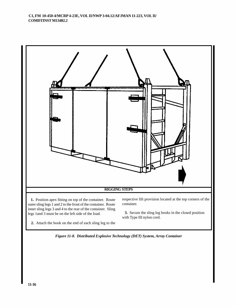
C1, FM 10-450-4/MCRP 4-23E, VOL II/NWP 3-04.12/AFJMAN 11-223, VOL II/COMDTINST M13482.2
11-16
1. Position apex fitting on top of the container. Routeouter sling legs 1 and 2 to the front of the container. Routeinner sling legs 3 and 4 to the rear of the container. Slinglegs 1and 3 must be on the left side of the load.
2. Attach the hook on the end of each sling leg to the
Figure 11-8. Distributed Explosive Technology (DET) System, Array Container
RIGGING STEPS
respective lift provision located at the top corners of thecontainer.
3. Secure the sling leg hooks in the closed positionwith Type III nylon cord.
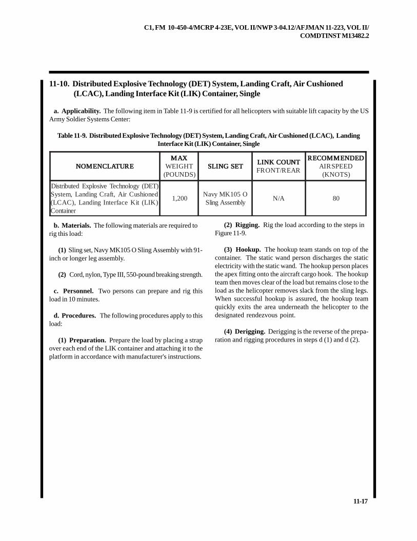
C1, FM 10-450-4/MCRP 4-23E, VOL II/NWP 3-04.12/AFJMAN 11-223, VOL II/COMDTINST M13482.2
11-17
11-10. Distributed Explosive Technology (DET) System, Landing Craft, Air Cushioned(LCAC), Landing Interface Kit (LIK) Container, Single
a. Applicability. The following item in Table 11-9 is certified for all helicopters with suitable lift capacity by the USArmy Soldier Systems Center:
Table 11-9. Distributed Explosive Technology (DET) System, Landing Craft, Air Cushioned (LCAC), LandingInterface Kit (LIK) Container, Single
b. Materials. The following materials are required torig this load:
(1) Sling set, Navy MK105 O Sling Assembly with 91-inch or longer leg assembly.
(2) Cord, nylon, Type III, 550-pound breaking strength.
c. Personnel. Two persons can prepare and rig thisload in 10 minutes.
d. Procedures. The following procedures apply to thisload:
(1) Preparation. Prepare the load by placing a strapover each end of the LIK container and attaching it to theplatform in accordance with manufacturer's instructions.
(2) Rigging. Rig the load according to the steps inFigure 11-9.
(3) Hookup. The hookup team stands on top of thecontainer. The static wand person discharges the staticelectricity with the static wand. The hookup person placesthe apex fitting onto the aircraft cargo hook. The hookupteam then moves clear of the load but remains close to theload as the helicopter removes slack from the sling legs.When successful hookup is assured, the hookup teamquickly exits the area underneath the helicopter to thedesignated rendezvous point.
(4) Derigging. Derigging is the reverse of the prepa-ration and rigging procedures in steps d (1) and d (2).
ERUTALCNEMON ERUTALCNEMON ERUTALCNEMON ERUTALCNEMON ERUTALCNEMONXAM XAM XAM XAM XAM
THGIEW)SDNUOP(
TESGNILS TESGNILS TESGNILS TESGNILS TESGNILSTNUOCKNIL TNUOCKNIL TNUOCKNIL TNUOCKNIL TNUOCKNILRAER/TNORF
DEDNEMMOCER DEDNEMMOCER DEDNEMMOCER DEDNEMMOCER DEDNEMMOCERDEEPSRIA)STONK(
)TED(ygolonhceTevisolpxEdetubirtsiDdenoihsuCriA,tfarCgnidnaL,metsyS)KIL(tiKecafretnIgnidnaL,)CACL(
reniatnoC
002,1O501KMyvaNylbmessAgnilS
A/N 08
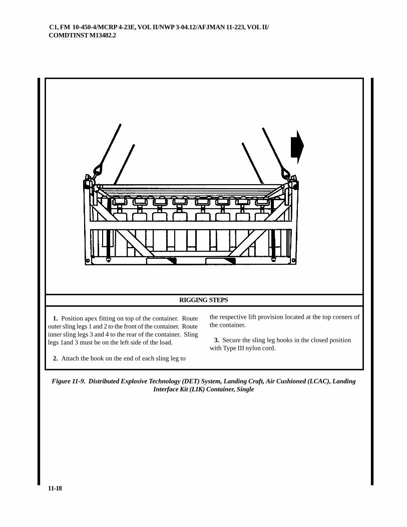
C1, FM 10-450-4/MCRP 4-23E, VOL II/NWP 3-04.12/AFJMAN 11-223, VOL II/COMDTINST M13482.2
11-18
RIGGING STEPS
Figure 11-9. Distributed Explosive Technology (DET) System, Landing Craft, Air Cushioned (LCAC), LandingInterface Kit (LIK) Container, Single
1. Position apex fitting on top of the container. Routeouter sling legs 1 and 2 to the front of the container. Routeinner sling legs 3 and 4 to the rear of the container. Slinglegs 1and 3 must be on the left side of the load.
2. Attach the hook on the end of each sling leg to
the respective lift provision located at the top corners ofthe container.
3. Secure the sling leg hooks in the closed positionwith Type III nylon cord.
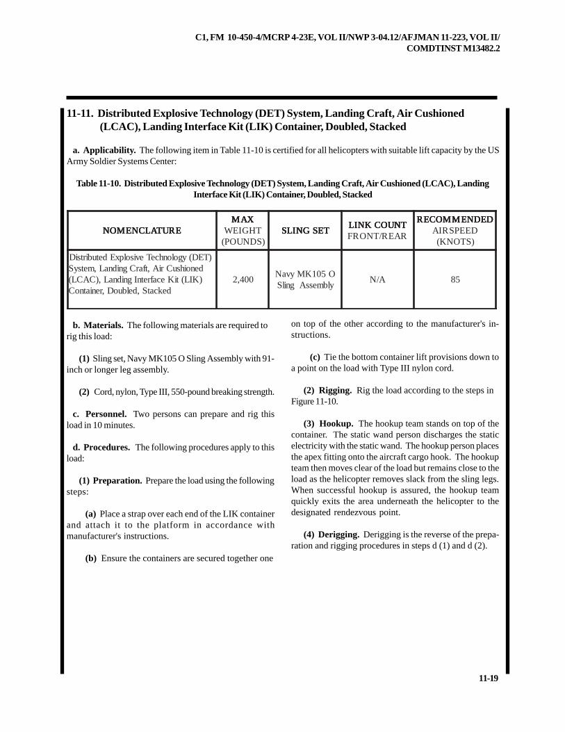
C1, FM 10-450-4/MCRP 4-23E, VOL II/NWP 3-04.12/AFJMAN 11-223, VOL II/COMDTINST M13482.2
11-19
11-11. Distributed Explosive Technology (DET) System, Landing Craft, Air Cushioned(LCAC), Landing Interface Kit (LIK) Container, Doubled, Stacked
a. Applicability. The following item in Table 11-10 is certified for all helicopters with suitable lift capacity by the USArmy Soldier Systems Center:
Table 11-10. Distributed Explosive Technology (DET) System, Landing Craft, Air Cushioned (LCAC), LandingInterface Kit (LIK) Container, Doubled, Stacked
b. Materials. The following materials are required torig this load:
(1) Sling set, Navy MK105 O Sling Assembly with 91-inch or longer leg assembly.
(2) Cord, nylon, Type III, 550-pound breaking strength.
c. Personnel. Two persons can prepare and rig thisload in 10 minutes.
d. Procedures. The following procedures apply to thisload:
(1) Preparation. Prepare the load using the followingsteps:
(a) Place a strap over each end of the LIK containerand attach it to the platform in accordance withmanufacturer's instructions.
(b) Ensure the containers are secured together one
on top of the other according to the manufacturer's in-structions.
(c) Tie the bottom container lift provisions down toa point on the load with Type III nylon cord.
(2) Rigging. Rig the load according to the steps inFigure 11-10.
(3) Hookup. The hookup team stands on top of thecontainer. The static wand person discharges the staticelectricity with the static wand. The hookup person placesthe apex fitting onto the aircraft cargo hook. The hookupteam then moves clear of the load but remains close to theload as the helicopter removes slack from the sling legs.When successful hookup is assured, the hookup teamquickly exits the area underneath the helicopter to thedesignated rendezvous point.
(4) Derigging. Derigging is the reverse of the prepa-ration and rigging procedures in steps d (1) and d (2).
ERUTALCNEMON ERUTALCNEMON ERUTALCNEMON ERUTALCNEMON ERUTALCNEMONXAM XAM XAM XAM XAM
THGIEW)SDNUOP(
TESGNILS TESGNILS TESGNILS TESGNILS TESGNILSTNUOCKNIL TNUOCKNIL TNUOCKNIL TNUOCKNIL TNUOCKNILRAER/TNORF
DEDNEMMOCER DEDNEMMOCER DEDNEMMOCER DEDNEMMOCER DEDNEMMOCERDEEPSRIA)STONK(
)TED(ygolonhceTevisolpxEdetubirtsiDdenoihsuCriA,tfarCgnidnaL,metsyS)KIL(tiKecafretnIgnidnaL,)CACL(
dekcatS,delbuoD,reniatnoC004,2
O501KMyvaNylbmessAgnilS
A/N 58
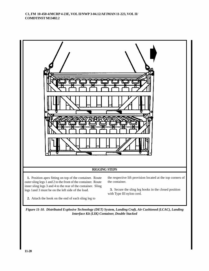
C1, FM 10-450-4/MCRP 4-23E, VOL II/NWP 3-04.12/AFJMAN 11-223, VOL II/COMDTINST M13482.2
11-20
RIGGING STEPS
Figure 11-10. Distributed Explosive Technology (DET) System, Landing Craft, Air Cushioned (LCAC), LandingInterface Kit (LIK) Container, Double Stacked
1. Position apex fitting on top of the container. Routeouter sling legs 1 and 2 to the front of the container. Routeinner sling legs 3 and 4 to the rear of the container. Slinglegs 1and 3 must be on the left side of the load.
2. Attach the hook on the end of each sling leg to
the respective lift provision located at the top corners ofthe container.
3. Secure the sling leg hooks in the closed positionwith Type III nylon cord.
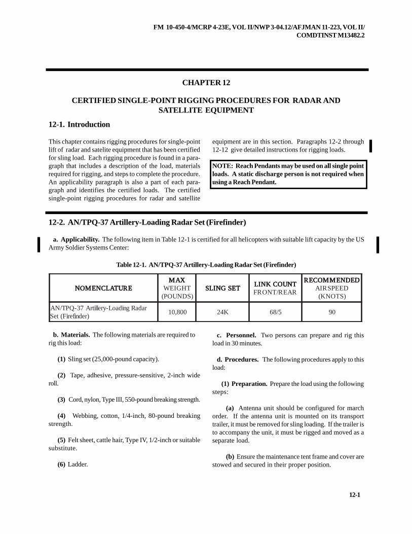
FM 10-450-4/MCRP 4-23E, VOL II/NWP 3-04.12/AFJMAN 11-223, VOL II/COMDTINST M13482.2
12-1
CHAPTER 12
CERTIFIED SINGLE-POINT RIGGING PROCEDURES FOR RADAR ANDSATELLITE EQUIPMENT
12-1. Introduction
This chapter contains rigging procedures for single-pointlift of radar and satelite equipment that has been certifiedfor sling load. Each rigging procedure is found in a para-graph that includes a description of the load, materialsrequired for rigging, and steps to complete the procedure.An applicability paragraph is also a part of each para-graph and identifies the certified loads. The certifiedsingle-point rigging procedures for radar and satellite
12-2. AN/TPQ-37 Artillery-Loading Radar Set (Firefinder)
a. Applicability. The following item in Table 12-1 is certified for all helicopters with suitable lift capacity by the USArmy Soldier Systems Center:
Table 12-1. AN/TPQ-37 Artillery-Loading Radar Set (Firefinder)
b. Materials. The following materials are required torig this load:
(1) Sling set (25,000-pound capacity).
(2) Tape, adhesive, pressure-sensitive, 2-inch wideroll.
(3) Cord, nylon, Type III, 550-pound breaking strength.
(4) Webbing, cotton, 1/4-inch, 80-pound breakingstrength.
(5) Felt sheet, cattle hair, Type IV, 1/2-inch or suitablesubstitute.
(6) Ladder.
c. Personnel. Two persons can prepare and rig thisload in 30 minutes.
d. Procedures. The following procedures apply to thisload:
(1) Preparation. Prepare the load using the followingsteps:
(a) Antenna unit should be configured for marchorder. If the antenna unit is mounted on its transporttrailer, it must be removed for sling loading. If the trailer isto accompany the unit, it must be rigged and moved as aseparate load.
(b) Ensure the maintenance tent frame and cover arestowed and secured in their proper position.
equipment are in this section. Paragraphs 12-2 through12-12 give detailed instructions for rigging loads.
NOTE: Reach Pendants may be used on all single pointloads. A static discharge person is not required whenusing a Reach Pendant.
ERUTALCNEMON ERUTALCNEMON ERUTALCNEMON ERUTALCNEMON ERUTALCNEMONXAM XAM XAM XAM XAM
THGIEW)SDNUOP(
TESGNILS TESGNILS TESGNILS TESGNILS TESGNILSTNUOCKNIL TNUOCKNIL TNUOCKNIL TNUOCKNIL TNUOCKNILRAER/TNORF
DEDNEMMOCER DEDNEMMOCER DEDNEMMOCER DEDNEMMOCER DEDNEMMOCERDEEPSRIA)STONK(
radaRgnidaoL-yrellitrA73-QPT/NA)redniferiF(teS
008,01 K42 5/86 09
FM 10-450-4/MCRP 4-23E, VOL II/NWP 3-04.12/AFJMAN 11-223, VOL II/COMDTINST M13482.2
12-2
(c) Ensure all cover panels, cabinet doors, and ventsare installed and secured.
(d) Secure all loose items with Type III nylon cord.
(e) Ensure the rear door is closed and secured withthe locking handle. Door rods must be secured in theirclips.
(f) Ensure the antenna transport cover is securedtightly to the lacing brackets with bungee cord. If neces-sary, secure the antenna with additional nylon cord.
(2) Rigging. Rig the load according to the steps inFigure 12-1.
CAUTIONDo not stand on top of the load. Use the
ladder to connect the sling legs to the load.
(3) Hookup. The hookup team remains close to theload as the helicopter removes slack from the sling legs.When successful hookup is assured, the hookup teamquickly exits the area underneath the helicopter to thedesignated rendezvous point.
NOTE: Hookup is accomplished by the flight engineerusing a cargo-hook loading pole (Shepard's Hook). En-sure the helicopter crew is informed of this in advance.
(4) Derigging. Derigging is the reverse of the prepa-ration and rigging procedures in steps d (1) and d (2).
NOTE: Advise the pilot to hover to one side before releas-ing the apex fitting from the cargo hook .
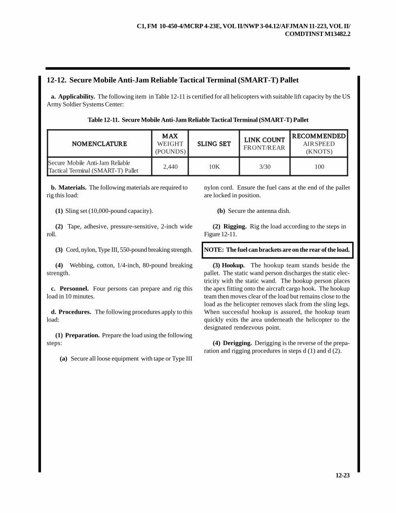
C1, FM 10-450-4/MCRP 4-23E, VOL II/NWP 3-04.12/AFJMAN 11-223, VOL II/COMDTINST M13482.2
12-23
12-12. Secure Mobile Anti-Jam Reliable Tactical Terminal (SMART-T) Pallet
a. Applicability. The following item in Table 12-11 is certified for all helicopters with suitable lift capacity by the USArmy Soldier Systems Center:
Table 12-11. Secure Mobile Anti-Jam Reliable Tactical Terminal (SMART-T) Pallet
b. Materials. The following materials are required torig this load:
(1) Sling set (10,000-pound capacity).
(2) Tape, adhesive, pressure-sensitive, 2-inch wideroll.
(3) Cord, nylon, Type III, 550-pound breaking strength.
(4) Webbing, cotton, 1/4-inch, 80-pound breakingstrength.
c. Personnel. Four persons can prepare and rig thisload in 10 minutes.
d. Procedures. The following procedures apply to thisload:
(1) Preparation. Prepare the load using the followingsteps:
(a) Secure all loose equipment with tape or Type III
nylon cord. Ensure the fuel cans at the end of the palletare locked in position.
(b) Secure the antenna dish.
(2) Rigging. Rig the load according to the steps inFigure 12-11.
NOTE: The fuel can brackets are on the rear of the load.
(3) Hookup. The hookup team stands beside thepallet. The static wand person discharges the static elec-tricity with the static wand. The hookup person placesthe apex fitting onto the aircraft cargo hook. The hookupteam then moves clear of the load but remains close to theload as the helicopter removes slack from the sling legs.When successful hookup is assured, the hookup teamquickly exits the area underneath the helicopter to thedesignated rendezvous point.
(4) Derigging. Derigging is the reverse of the prepa-ration and rigging procedures in steps d (1) and d (2).
ERUTALCNEMON ERUTALCNEMON ERUTALCNEMON ERUTALCNEMON ERUTALCNEMONXAM XAM XAM XAM XAM
THGIEW)SDNUOP(
TESGNILS TESGNILS TESGNILS TESGNILS TESGNILSTNUOCKNIL TNUOCKNIL TNUOCKNIL TNUOCKNIL TNUOCKNILRAER/TNORF
DEDNEMMOCER DEDNEMMOCER DEDNEMMOCER DEDNEMMOCER DEDNEMMOCERDEEPSRIA)STONK(
elbaileRmaJ-itnAeliboMeruceStellaP)T-TRAMS(lanimreTlacitcaT
044,2 K01 03/3 001
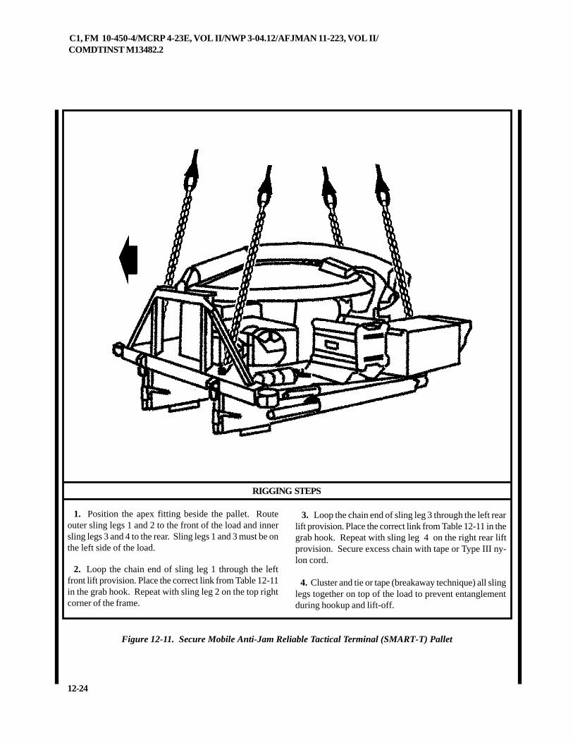
C1, FM 10-450-4/MCRP 4-23E, VOL II/NWP 3-04.12/AFJMAN 11-223, VOL II/COMDTINST M13482.2
12-24
1. Position the apex fitting beside the pallet. Routeouter sling legs 1 and 2 to the front of the load and innersling legs 3 and 4 to the rear. Sling legs 1 and 3 must be onthe left side of the load.
2. Loop the chain end of sling leg 1 through the leftfront lift provision. Place the correct link from Table 12-11in the grab hook. Repeat with sling leg 2 on the top rightcorner of the frame.
3. Loop the chain end of sling leg 3 through the left rearlift provision. Place the correct link from Table 12-11 in thegrab hook. Repeat with sling leg 4 on the right rear liftprovision. Secure excess chain with tape or Type III ny-lon cord.
4. Cluster and tie or tape (breakaway technique) all slinglegs together on top of the load to prevent entanglementduring hookup and lift-off.
RIGGING STEPS
Figure 12-11. Secure Mobile Anti-Jam Reliable Tactical Terminal (SMART-T) Pallet
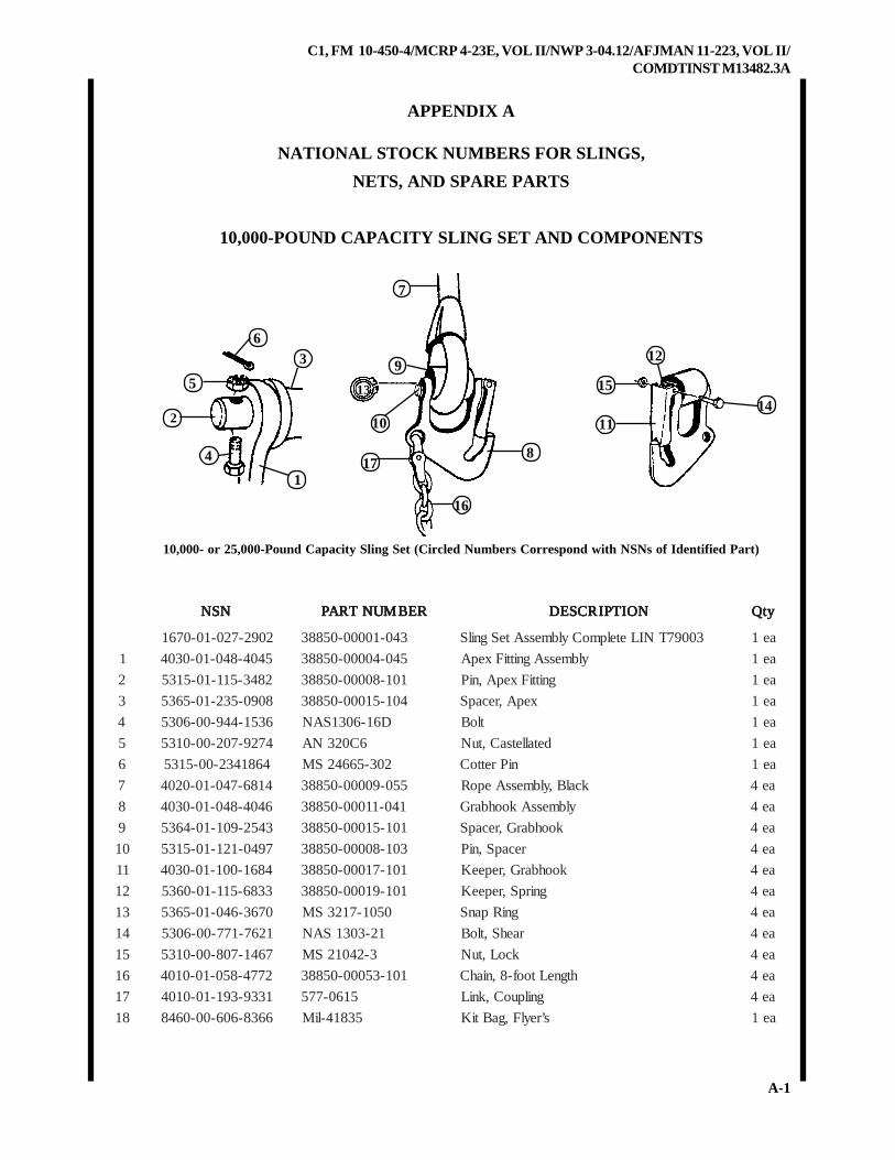
C1, FM 10-450-4/MCRP 4-23E, VOL II/NWP 3-04.12/AFJMAN 11-223, VOL II/COMDTINST M13482.3A
A-1
123
15
112
84
APPENDIX A
NATIONAL STOCK NUMBERS FOR SLINGS,
NETS, AND SPARE PARTS
10,000-POUND CAPACITY SLING SET AND COMPONENTS
9
10
17
16
14
6
5
1
10,000- or 25,000-Pound Capacity Sling Set (Circled Numbers Correspond with NSNs of Identified Part)
7
13
NSN NSN NSN NSN NSN REBMUNTRAP REBMUNTRAP REBMUNTRAP REBMUNTRAP REBMUNTRAP NOITPIRCSED NOITPIRCSED NOITPIRCSED NOITPIRCSED NOITPIRCSED ytQ ytQ ytQ ytQ ytQ
2092-720-10-0761 340-10000-05883 30097TNILetelpmoCylbmessAteSgnilS ae1
1 5404-840-10-0304 540-40000-05883 ylbmessAgnittiFxepA ae1
2 2843-511-10-5135 101-80000-05883 gnittiFxepA,niP ae1
3 8090-532-10-5635 401-51000-05883 xepA,recapS ae1
4 6351-449-00-6035 D61-6031SAN tloB ae1
5 4729-702-00-0135 6C023NA detalletsaC,tuN ae1
6 4681432-00-5135 203-56642SM niPrettoC ae1
7 4186-740-10-0204 550-90000-05883 kcalB,ylbmessAepoR ae4
8 6404-840-10-0304 140-11000-05883 ylbmessAkoohbarG ae4
9 3452-901-10-4635 101-51000-05883 koohbarG,recapS ae4
01 7940-121-10-5135 301-80000-05883 recapS,niP ae4
11 4861-001-10-0304 101-71000-05883 koohbarG,repeeK ae4
21 3386-511-10-0635 101-91000-05883 gnirpS,repeeK ae4
31 0763-640-10-5635 0501-7123SM gniRpanS ae4
41 1267-177-00-6035 12-3031SAN raehS,tloB ae4
51 7641-708-00-0135 3-24012SM kcoL,tuN ae4
61 2774-850-10-0104 101-35000-05883 htgneLtoof-8,niahC ae4
71 1339-391-10-0104 5160-775 gnilpuoC,kniL ae4
81 6638-606-00-0648 53814-liM s’reylF,gaBtiK ae1
C1, FM 10-450-4/MCRP 4-23E, VOL II/NWP 3-04.12/AFJMAN 11-223, VOL II/COMDTINST M13482.3A
A-2
25,000-POUND CAPACITY SLING SET AND COMPONENTS
NSN NSN NSN NSN NSN REBMUNTRAP REBMUNTRAP REBMUNTRAP REBMUNTRAP REBMUNTRAP NOITPIRCSED NOITPIRCSED NOITPIRCSED NOITPIRCSED NOITPIRCSED ytQ ytQ ytQ ytQ ytQ
0092-720-10-0761 440-10000-05883 90097TNILetelpmoCylbmessAteSgnilS ae1
1 4404-840-10-0304 640-40000-05883 ylbmessAelkcahS ae1
2 5609-911-10-5135 201-80000-05883 gnittiFxepA,niP ae1
3 7090-532-10-0761 501-51000-05883 xepA,recapS ae1
4 9562-449-00-6035 D22-6031SAN tloB ae1
5 4729-702-00-0135 6C023NA detalletsaC,tuN ae1
6 4681-432-00-5135 203-56642SM niPrettoC ae1
7 5186-740-10-0761 650-90000-05883 ylbmessAepoR ae4
8 7404-840-10-0304 640-11000-05883 ylbmessAkoohbarG ae4
9 4452-901-10-0761 201-51000-05883 koohbarG,recapS ae4
01 4782-121-10-5135 401-80000-05883 recapS,niP ae4
11 5861-001-10-0304 201-71000-05883 kooHytefaS,hctaL ae4
21 3386-511-10-0635 101-91000-05883 gnirpS,repeeK ae4
31 8193-162-00-5635 5701-7123SM gniRpanS ae4
41 1267-177-00-6035 12-3031SAN raehS,tloB ae4
51 7641-708-00-0135 3-24012SM rehsaWdednapxE ae4
61 1774-850-10-0104 201-35000-05883 htgneLtoof-8,niahC ae4
71 1579-140-10-0104 142466 gnilpuoC,kniL ae4
81 6638-606-00-0648 53814-liM s’reylF,gaBtiK ae1
C1, FM 10-450-4/MCRP 4-23E, VOL II/NWP 3-04.12/AFJMAN 11-223, VOL II/COMDTINST M13482.3A
A-3
15,000-POUND CAPACITY MULTILEG SLING ASSEMBLY
NSN NSN NSN NSN NSN REBMUNTRAP REBMUNTRAP REBMUNTRAP REBMUNTRAP REBMUNTRAP NOITPIRCSED NOITPIRCSED NOITPIRCSED NOITPIRCSED NOITPIRCSED ytQ ytQ ytQ ytQ ytQ
0803-209-00-0761 1600093175087TNIL,ylbmessagel-itlum,gnilS
0302BNCMATae1
9178-649-00-5635 2920006CA ylbmessagniRbeW ae1
3426-917-00-0761 1-35542SM gniRbeW,ylbmessAkniL ae1
1368-649-00-0761 7610113 ylbmessagelgnilS ae4
AN 5-2110193 ylbmessagel,hcni-5,repeeK ae4
AN 1-110193 ylbmessagel,hcni-4/16,repeeK ae4
3436-917-00-0761 1-35542SM gelgnils,ylbmessakniL ae1
AN 01613 knilbarG ae4
AN 3-3267EF knilbarg,repeeK ae4
AN 81-21043 knilbarg,repeekgnirpS ae4
8180-761-00-0135 f3630f5411SAN knilbarg,repeekrehsaW ae4
5673-218-00-5135 3302-29302SM knilbarg,repeek,niP ae4
5232-938-00-5135 231-56642SM knilbarg,repeek,niprettoC ae4
AN 11613 knilgnilpuoC ae4
AN 4-08043 niahC ae4
C1, FM 10-450-4/MCRP 4-23E, VOL II/NWP 3-04.12/AFJMAN 11-223, VOL II/COMDTINST M13482.3A
A-4
40,000-POUND CAPACITY SLING SET AND COMPONENTS
NSN NSN NSN NSN NSN REBMUNTRAP REBMUNTRAP REBMUNTRAP REBMUNTRAP REBMUNTRAP NOITPIRCSED NOITPIRCSED NOITPIRCSED NOITPIRCSED NOITPIRCSED ytQ ytQ ytQ ytQ ytQ
8112-381-10-0493 NCMAT etelpmoCylbmessAteSgnilS ae1
2659-991-10-0304 1-9018EF ylbmessaelkcahsxepA ae1
AN 5-9018EF elkcahS ae1
AN 3-9018EF xepa,elkcahs,niP ae1
AN 2-9018EF xepa,elkcahs,recapS ae1
1397-367-00-6035 D12-6031SAN raehs,tloB ae1
0118-671-00-0135 6-023NA xeh,nialp,detalletsac,tuN ae1
4681-432-00-5135 203-56642SM niPrettoC ae1
4639-491-10-0493 0002-CMWSTEJ gelgnilS ae4
9261-791-10-0304 1-3018EF ylbmessaelkcahS ae4
AN 4-3018EF knilbarg,recapS ae4
2841-151-00-6035 24-21NA knilbarg,tloB ae4
2921-761-00-0135 21-013NA xeh,nialp,detalletsac,nialp,tuN ae4
1617-582-00-5135 3302-29302SM rettoc,niP ae4
AN 81-21043 knilbarg,repeek,gnirpS ae4
8180-761-00-0135 01-069NA knilbarg,repeek,rehsaW ae4
5232-938-00-5135 231-56642SM knilbarg,repeek,niprettoC ae4
4115-180-10-0104 5180-775 gnilpuoC,kniL ae4
AN 050706 toof-8,niahC ae4
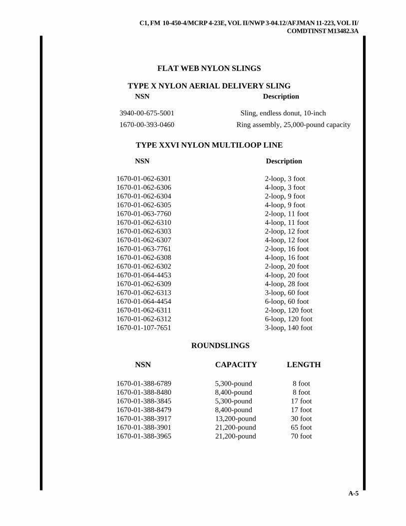
C1, FM 10-450-4/MCRP 4-23E, VOL II/NWP 3-04.12/AFJMAN 11-223, VOL II/COMDTINST M13482.3A
A-5
FLAT WEB NYLON SLINGS
TYPE X NYLON AERIAL DELIVERY SLING NSN Description
3940-00-675-5001 Sling, endless donut, 10-inch
1670-00-393-0460 Ring assembly, 25,000-pound capacity
TYPE XXVI NYLON MULTILOOP LINE
NSN Description
1670-01-062-6301 2-loop, 3 foot1670-01-062-6306 4-loop, 3 foot1670-01-062-6304 2-loop, 9 foot1670-01-062-6305 4-loop, 9 foot1670-01-063-7760 2-loop, 11 foot1670-01-062-6310 4-loop, 11 foot1670-01-062-6303 2-loop, 12 foot1670-01-062-6307 4-loop, 12 foot1670-01-063-7761 2-loop, 16 foot1670-01-062-6308 4-loop, 16 foot1670-01-062-6302 2-loop, 20 foot1670-01-064-4453 4-loop, 20 foot1670-01-062-6309 4-loop, 28 foot1670-01-062-6313 3-loop, 60 foot1670-01-064-4454 6-loop, 60 foot1670-01-062-6311 2-loop, 120 foot1670-01-062-6312 6-loop, 120 foot1670-01-107-7651 3-loop, 140 foot
ROUNDSLINGS
NSN CAPACITY LENGTH
1670-01-388-6789 5,300-pound 8 foot1670-01-388-8480 8,400-pound 8 foot1670-01-388-3845 5,300-pound 17 foot1670-01-388-8479 8,400-pound 17 foot1670-01-388-3917 13,200-pound 30 foot1670-01-388-3901 21,200-pound 65 foot1670-01-388-3965 21,200-pound 70 foot
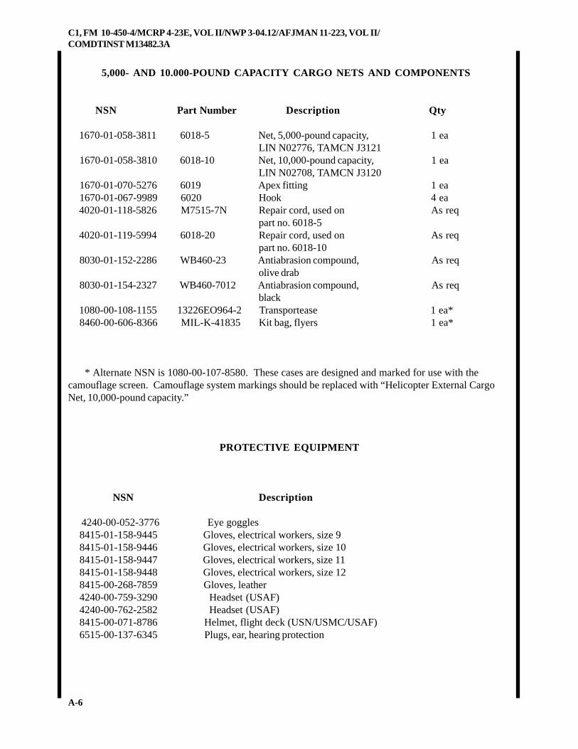
C1, FM 10-450-4/MCRP 4-23E, VOL II/NWP 3-04.12/AFJMAN 11-223, VOL II/COMDTINST M13482.3A
A-6
5,000- AND 10.000-POUND CAPACITY CARGO NETS AND COMPONENTS
NSN Part Number Description Qty
1670-01-058-3811 6018-5 Net, 5,000-pound capacity, 1 eaLIN N02776, TAMCN J3121
1670-01-058-3810 6018-10 Net, 10,000-pound capacity, 1 eaLIN N02708, TAMCN J3120
1670-01-070-5276 6019 Apex fitting 1 ea 1670-01-067-9989 6020 Hook 4 ea 4020-01-118-5826 M7515-7N Repair cord, used on As req
part no. 6018-5 4020-01-119-5994 6018-20 Repair cord, used on As req
part no. 6018-10 8030-01-152-2286 WB460-23 Antiabrasion compound, As req
olive drab 8030-01-154-2327 WB460-7012 Antiabrasion compound, As req
black 1080-00-108-1155 13226EO964-2 Transportease 1 ea* 8460-00-606-8366 MIL-K-41835 Kit bag, flyers 1 ea*
* Alternate NSN is 1080-00-107-8580. These cases are designed and marked for use with thecamouflage screen. Camouflage system markings should be replaced with “Helicopter External CargoNet, 10,000-pound capacity.”
PROTECTIVE EQUIPMENT
NSN Description
4240-00-052-3776 Eye goggles 8415-01-158-9445 Gloves, electrical workers, size 9 8415-01-158-9446 Gloves, electrical workers, size 10 8415-01-158-9447 Gloves, electrical workers, size 11 8415-01-158-9448 Gloves, electrical workers, size 12 8415-00-268-7859 Gloves, leather 4240-00-759-3290 Headset (USAF) 4240-00-762-2582 Headset (USAF) 8415-00-071-8786 Helmet, flight deck (USN/USMC/USAF) 6515-00-137-6345 Plugs, ear, hearing protection

C1, FM 10-450-4/MCRP 4-23E, VOL II/NWP 3-04.12/AFJMAN 11-223, VOL II/COMDTINST M13482.3A
A-7
MISCELLANEOUS EQUIPMENT AND MATERIAL
NSN Description
4030-00-360-0304 Clevis assembly, small, MS 70087-15305-00-726-2553 Bolt, Screw Cap, Hexagon Head5310-00-835-2037 Nut, Plain, Hexagon4030-00-678-8562 Clevis assembly, medium, MS 70087-2, Shackle5305-00-940-8069 Bolt, Screw Cap, Hexagon Head5310-00-842-1190 Nut, Plain, Hexagon4030-00-090-5354 Clevis assembly, large, MS 70087-3, Shackle5305-00-177-5617 Bolt, Screw Cap, Hexagon Head5310-00-891-3428 Nut, Plain, Hexagon4020-00-240-2146 Cord, nylon, Type III, 550-pound breaking strength8305-00-958-3685 Felt sheeting, 1/2-inch thick, 30-inch wide8305-00-191-1101 Felt sheeting, 1/2-inch thick, 60-inch wide7510-00-079-0286 Ink, marking, parachute, orange-yellow, marker7520-00-634-6583 Ink, marking, parachute, orange-yellow, liquid7510-00-230-2734 Ink, marking, parachute, strata-blue, marker7520-00-286-5362 Ink, marking, parachute, strata-blue, liquid5825-00-917-3738 Light, beacon, beanbag6260-01-074-4230 Light, chemical wand, 30-minute glow time, Yellow6260-00-106-7478 Light, chemical wand, 6-hour glow time, Green6260-01-074-4229 Light, chemical wand, 12-hour glow time, Green1670-00-783-5988 Link assembly, Type IV1670-00-212-1149 Rachet, Adjustable, Assembly, Tiedown1670-00-516-8405 Tiedown, Cargo, Aircraft, 10,000-pound capacity1670-00-753-3928 Pad, energy-dissipating, honeycomb8135-00-664-6958 Padding, cellulose, 20-inch by 60-foot8135-00-808-6446 Padding, cellulose, 24-inch by 125-foot8345-00-174-6865 Panel, marker, red-yellow, VS-17, orange4020-00-231-2581 Rope, 3/8-inch, TR605, Natural4020-00-968-1357 Rope, fibrous, 1/2-inch, MIL-R-173436850-00-264-9038 Solvent, dry cleaning, PD-6807510-00-266-5016 Tape, adhesive, pressure-sensitive, 2-inch wide roll, green
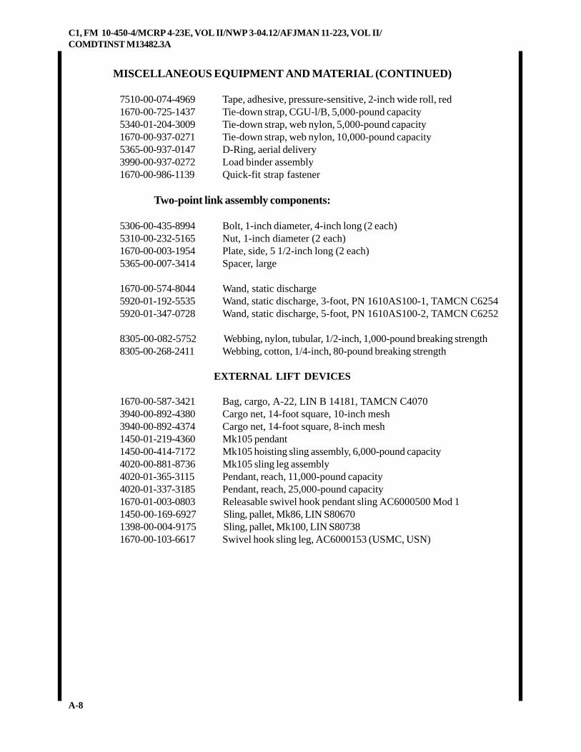
C1, FM 10-450-4/MCRP 4-23E, VOL II/NWP 3-04.12/AFJMAN 11-223, VOL II/COMDTINST M13482.3A
A-8
MISCELLANEOUS EQUIPMENT AND MATERIAL (CONTINUED)
7510-00-074-4969 Tape, adhesive, pressure-sensitive, 2-inch wide roll, red1670-00-725-1437 Tie-down strap, CGU-l/B, 5,000-pound capacity5340-01-204-3009 Tie-down strap, web nylon, 5,000-pound capacity1670-00-937-0271 Tie-down strap, web nylon, 10,000-pound capacity5365-00-937-0147 D-Ring, aerial delivery3990-00-937-0272 Load binder assembly1670-00-986-1139 Quick-fit strap fastener
Two-point link assembly components:
5306-00-435-8994 Bolt, 1-inch diameter, 4-inch long (2 each)5310-00-232-5165 Nut, 1-inch diameter (2 each)1670-00-003-1954 Plate, side, 5 1/2-inch long (2 each)5365-00-007-3414 Spacer, large
1670-00-574-8044 Wand, static discharge5920-01-192-5535 Wand, static discharge, 3-foot, PN 1610AS100-1, TAMCN C62545920-01-347-0728 Wand, static discharge, 5-foot, PN 1610AS100-2, TAMCN C6252
8305-00-082-5752 Webbing, nylon, tubular, 1/2-inch, 1,000-pound breaking strength8305-00-268-2411 Webbing, cotton, 1/4-inch, 80-pound breaking strength
EXTERNAL LIFT DEVICES
1670-00-587-3421 Bag, cargo, A-22, LIN B 14181, TAMCN C40703940-00-892-4380 Cargo net, 14-foot square, 10-inch mesh3940-00-892-4374 Cargo net, 14-foot square, 8-inch mesh1450-01-219-4360 Mk105 pendant1450-00-414-7172 Mk105 hoisting sling assembly, 6,000-pound capacity4020-00-881-8736 Mk105 sling leg assembly4020-01-365-3115 Pendant, reach, 11,000-pound capacity4020-01-337-3185 Pendant, reach, 25,000-pound capacity1670-01-003-0803 Releasable swivel hook pendant sling AC6000500 Mod 11450-00-169-6927 Sling, pallet, Mk86, LIN S806701398-00-004-9175 Sling, pallet, Mk100, LIN S807381670-00-103-6617 Swivel hook sling leg, AC6000153 (USMC, USN)
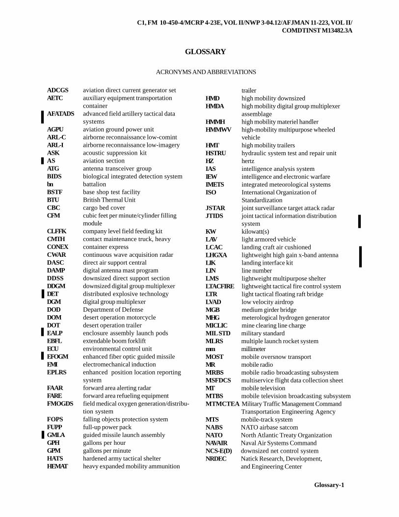
C1, FM 10-450-4/MCRP 4-23E, VOL II/NWP 3-04.12/AFJMAN 11-223, VOL II/COMDTINST M13482.3A
Glossary-1
GLOSSARY
ACRONYMS AND ABBREVIATIONS
ADCGS aviation direct current generator setAETC auxiliary equipment transportation
containerAFATADS advanced field artillery tactical data
systemsAGPU aviation ground power unitARL-C airborne reconnaissance low-comintARL-I airborne reconnaissance low-imageryASK acoustic suppression kitAS aviation sectionATG antenna transceiver groupBIDS biological integrated detection systembn battalionBSTF base shop test facilityBTU British Thermal UnitCBC cargo bed coverCFM cubic feet per minute/cylinder filling
moduleCLFFK company level field feeding kitCMTH contact maintenance truck, heavyCONEX container expressCWAR continuous wave acquisition radarDASC direct air support centralDAMP digital antenna mast programDDSS downsized direct support sectionDDGM downsized digital group multiplexerDET distributed explosive technologyDGM digital group multiplexerDOD Department of DefenseDOM desert operation motorcycleDOT desert operation trailerEALP enclosure assembly launch podsEBFL extendable boom forkliftECU environmental control unitEFOGM enhanced fiber optic guided missileEMI electromechanical inductionEPLRS enhanced position location reporting
systemFAAR forward area alerting radarFARE forward area refueling equipmentFMOGDS field medical oxygen generation/distribu-
tion systemFOPS falling objects protection systemFUPP full-up power packGMLA guided missile launch assemblyGPH gallons per hourGPM gallons per minuteHATS hardened army tactical shelterHEMAT heavy expanded mobility ammunition
trailerHMD high mobility downsizedHMDA high mobility digital group multiplexer
assemblageHMMH high mobility materiel handlerHMMWV high-mobility multipurpose wheeled
vehicleHMT high mobility trailersHSTRU hydraulic system test and repair unitHZ hertzIAS intelligence analysis systemIEW intelligence and electronic warfareIMETS integrated meteorological systemsISO International Organization of
StandardizationJSTAR joint surveillance target attack radarJTIDS joint tactical information distribution
systemKW kilowatt(s)LAV light armored vehicleLCAC landing craft air cushionedLHGXA lightweight high gain x-band antennaLIK landing interface kitLIN line numberLMS lightweight multipurpose shelterLTACFIRE lightweight tactical fire control systemLTR light tactical floating raft bridgeLVAD low velocity airdropMGB medium girder bridgeMHG meterological hydrogen generatorMICLIC mine clearing line chargeMIL STD military standardMLRS multiple launch rocket systemmm millimeterMOST mobile oversnow transportMR mobile radioMRBS mobile radio broadcasting subsystemMSFDCS multiservice flight data collection sheetMT mobile televisionMTBS mobile television broadcasting subsystemMTMCTEA Military Traffic Management Command
Transportation Engineering AgencyMTS mobile-track systemNABS NATO airbase satcomNATO North Atlantic Treaty OrganizationNAVAIR Naval Air Systems CommandNCS-E(D) downsized net control systemNRDEC Natick Research, Development,
and Engineering Center
C1, FM 10-450-4/MCRP 4-23E, VOL II/NWP 3-04.12/AFJMAN 11-223, VOL II/COMDTINST M13482.3A
Glossary-2
NSN national stock numberOC operations centralOCG operational control groupOGDM oxygen generation/distribution moduleOVE operator vehicle equipmentPN part numberPOC platoon operations centerPTO pioneer tool outfitQRSA quick reaction satellite antennaRIE required individual equipmentRLST remote landing site towerROPS roll-over protection systemROWPU reverse osmosis water purification unitRP/C rocket pod/containerRT rough terrainSCAMP self-propelled crane for Army aircraft
maintenance and positioningSCOTT single channel objective tactical terminalSDASS special diver's air support systemSEE small emplacement excavator
SICPS standardized integrated command postsystems
SIXCON six-compartment containerSMART-T secure mobile anti-jam tactical terminalSMMS sensor mobile monitoring systemSPAM shop, portable aircraft maintenanceSUSV small unit support vehicleTAFDS tactical airfield fuel dispensing systemTAMCN Table of Authorized Material Control
NumberTM technical manualTOW tube launched, optically tracked,
wireguidedTQG tactical quiet generatorTRSS tactical remote sensor systemTSS tracked suspension systemTTCS tactical terminal control systemUS United StatesUSA United States ArmyUSMC United States Marine Corps
C1, FM 10-450-4/MCRP 4-23E, VOL II/NWP 3-04.12/AFJMAN 11-223, VOL II/COMDTINST M13482.3A
Reference-1
REFERENCES
REQUIRED PUBLICATIONS
Required publications are sources that users must read in order to understand or to comply with this publication.
MULTISERVICE PUBLICATION
AFJMAN 24-204/TM 38-250/NAVSUP PUB 505/MCO P 4030.19F/DLAM 4145.3, Packaging and Materials Handling:Preparing Hazardous Materials for Military Air Shipment. November 1994.
FM 10-450-3/MCRP4-23E, Vol I/NWP 3-04.11/AFJMAN 11-223, VOL I/COMDTINST M13482.2AMultiservice Helicopter Sling Load: Basic Operations and Equipment. April 1997.
MIL STD 913 - Requirements for the Certification of Sling Loaded Equipment for External Transportation by Departmentof Defense Helicopters. February 1997.
TM 9-2320-285-24&P - Unit, Direct Support, and General Support Maintenance Repair Parts and Special Tools Lists,Truck, Tractor, Yard-type: 43,500 GVW, DED, 4 x 2 (Army Model M878A1). June 1992.
TM 9-1015-252-10 - Operator's Manual for Howitzer, Light, Towed: 105-MM, M119A1. October 1992.
TM 9-1425-2585-10-1 - System Description of M48A2 (Chaparral Air Defense Guided Missile System). June 1984.
TM 9-1430-588-10 - Operator's Manual for Radar Set, AN/MPQ-49 (Forward Area Alerting Radar System). February 1986.
C1, FM 10-450-4MCRP 4-23E, VOL II
NWP 3-04.12AFJMAN 11-223, VOL II
COMDTINST M13482.3A 1 FEBRUARY 2000
DISTRIBUTION:
Active Army, Army National Guard, and U. S. Army Reserve: To be distributed inaccordance with the initial distribution number 114616, requirements forFM 10-450-4.
By Order of the Secretary of the Army:
ERIC K. SHINSEKIGeneral, United States Army
Chief of StaffOfficial:
JOEL B. HUDSONAdministrative Assistant to the
Secretary of the Army 9916607