Multiscale modeling of PVDF matrix carbon fiber compositesmgreming/papers/msmse2017.pdf · smart...
16
This content has been downloaded from IOPscience. Please scroll down to see the full text. Download details: This content was downloaded by: mgreming IP Address: 131.212.69.108 This content was downloaded on 19/04/2017 at 15:06 Please note that terms and conditions apply. Multiscale modeling of PVDF matrix carbon fiber composites View the table of contents for this issue, or go to the journal homepage for more 2017 Modelling Simul. Mater. Sci. Eng. 25 045007 (http://iopscience.iop.org/0965-0393/25/4/045007) Home Search Collections Journals About Contact us My IOPscience
Transcript of Multiscale modeling of PVDF matrix carbon fiber compositesmgreming/papers/msmse2017.pdf · smart...

This content has been downloaded from IOPscience. Please scroll down to see the full text.
Download details:
This content was downloaded by: mgreming
IP Address: 131.212.69.108
This content was downloaded on 19/04/2017 at 15:06
Please note that terms and conditions apply.
Multiscale modeling of PVDF matrix carbon fiber composites
View the table of contents for this issue, or go to the journal homepage for more
2017 Modelling Simul. Mater. Sci. Eng. 25 045007
(http://iopscience.iop.org/0965-0393/25/4/045007)
Home Search Collections Journals About Contact us My IOPscience
Multiscale modeling of PVDF matrix carbonfiber composites
Michael Greminger1,3 and Ghazaleh Haghiashtiani2
1Department of Mechanical and Industrial Engineering, University of MinnesotaDuluth, Duluth, MN 55812, United States of America2 Department of Mechanical Engineering, University of Minnesota, Minneapolis, MN55455, United States of America
E-mail: [email protected] and [email protected]
Received 28 December 2016, revised 21 March 2017Accepted for publication 31 March 2017Published 19 April 2017
AbstractSelf-sensing carbon fiber reinforced composites have the potential to enablestructural health monitoring that is inherent to the composite material ratherthan requiring external or embedded sensors. It has been demonstrated that aself-sensing carbon fiber reinforced polymer composite can be created byusing the piezoelectric polymer polyvinylidene difluoride (PVDF) as thematrix material and using a Kevlar layer to separate two carbon fiber layers. Inthis configuration, the electrically conductive carbon fiber layers act as elec-trodes and the Kevlar layer acts as a dielectric to prevent the electrical shortingof the carbon fiber layers. This composite material has been characterizedexperimentally for its effective d33 and d31 piezoelectric coefficients. However,for design purposes, it is desirable to obtain a predictive model of the effectivepiezoelectric coefficients for the final smart composite material. Also, theinverse problem can be solved to determine the degree of polarization obtainedin the PVDF material during polarization by comparing the effective d33 andd31 values obtained in experiment to those predicted by the finite elementmodel. In this study, a multiscale micromechanics and coupled piezoelectric-mechanical finite element modeling approach is introduced to predict themechanical and piezoelectric performance of a plain weave carbon fiberreinforced PVDF composite. The modeling results show good agreement withthe experimental results for the mechanical and electrical properties of thecomposite. In addition, the degree of polarization of the PVDF component ofthe composite is predicted using this multiscale modeling approach and showsthat there is opportunity to drastically improve the smart composite’s perfor-mance by improving the polarization procedure.
Modelling and Simulation in Materials Science and Engineering
Modelling Simul. Mater. Sci. Eng. 25 (2017) 045007 (15pp) https://doi.org/10.1088/1361-651X/aa6a8a
3 Author to whom any correspondence should be addressed.
0965-0393/17/045007+15$33.00 © 2017 IOP Publishing Ltd Printed in the UK 1
Keywords: micromechanics, multiscale modeling, piezoelectric materials,smart composites, carbon fiber reinforced polymer, polyvinylidene difluor-ide (PVDF)
(Some figures may appear in colour only in the online journal)
1. Introduction
Smart composite materials are enabled by replacing the typical polymer matrix used in carbonfiber reinforced polymers with the piezoelectric polymer polyvinylidene difluoride (PVDF).When a stress is applied to these smart composites, the PVDF material generates a charge dueto the piezoelectric effect. The resulting structure has strength and stiffness properties similarto conventional carbon fiber reinforced polymer structures, making it suitable for structuralapplications. Force sensing and structural health monitoring capabilities can be added tostructures by replacing conventional carbon fiber composite materials with these smartcomposite materials. Traditionally, these sensing capabilities could only be included in astructure by attaching external strain gauges to the structure [1, 2]. The use of smart com-posites materials in structural applications that require structure health monitoring simplifiesthe implementation by not requiring the application of separate strain gauges and also allowsstrain to be measured in locations that were not previously possible such as between the layersof the composite laminate. In addition to structural health monitoring, piezoelectric smartcomposites can be used for energy harvesting to enable wireless sensing in applications thatwould be difficult to measure in any other way [3]. One area where wireless sensing is anenabling technology is for the structural health monitoring of wind turbine blades [4].
In previous work, the authors have experimentally characterized the piezoelectric andmechanical properties of the proposed smart composite material [5]. In this previous work, thepiezoelectric coefficients were found to be lower for the smart composite than for the purePVDF material. This is to be expected since the carbon fiber and Kevlar components carry asignificant portion of the load, which impacts the amount of stress carried by the PVDFmaterial. An open question in the previous work was whether the PVDF material was beingfully polarized. In order to determine the degree of polarization, a modeling technique isrequired that predicts the piezoelectric properties of the composite structure based on theproperties of the constituent materials. This article presents a method that can efficientlypredict the electromechanical properties of the proposed smart composite structure. Note that,throughout this study, the piezoelectric coefficients are used as a proxy for the degree ofpolarization. Even though there is a direct relationship between remnant polarization and thepiezoelectric coefficients, in general, this relationship is quite complex and is not usuallyknown for a particular material and crystal structure [6].
Previous techniques for modeling piezoelectric composites have focused on the micro-mechanics approach of predicting the electromechanical properties of the composite at thescale of the inclusions [7–11]. These techniques have been shown to be accurate for pre-dicting the properties at the microscale. However, a micromechanics approach alone is notsufficient for predicting the properties of the proposed smart composite structure. This is dueto the millimeter scale properties of the composites. The millimeter scale properties comefrom the patterns of the plain weave carbon fiber and Kevlar fabrics in which the weft crossesover and under the warp. The mechanical properties of the weaves of textile composites havetypically been modeled using a finite element approach [12, 13]. The second scale of thesmart composite occurs at the scale of the carbon fiber and Kevlar tows that make up the
Modelling Simul. Mater. Sci. Eng. 25 (2017) 045007 M Greminger and G Haghiashtiani
2
weaves. These tows are made up of micron scale continuous fibers. In order to predict theelectrical and mechanical properties of the smart composite structure, a hybrid methodologyis required that uses a micromechanics approach to predict the electromechanical properties ofthe Kevlar and carbon fiber tows and a coupled finite element approach to predict theelectromechanical properties at the millimeter scale weave. This hybrid approach is intro-duced in this article. The contribution of this work is the use of a multiscale modelingapproach to predict the performance of a piezoelectric matrix woven composite. Previousstudies have only considered continuous fiber piezoelectric composites, which do not requirea multiscale modeling approach. Also, this work is the first to consider a piezoelectriccomposite with two types of reinforcement fibers (both carbon fiber and Kevlar) in a sand-wich structure, which is required in order to enable the sensing capabilities of the smartcomposite material.
The experimental characterization of the proposed smart composite structure is describedin section 2. Section 3 describes the millimeter scale solid model and mesh of the compositeweave structure. The micromechanics characterization of the Kevlar and carbon fiber tows isdescribed in section 4. Section 5 summarizes the finite element modeling results of the smartcomposite structure and the conclusions are discussed in section 6.
2. Smart composite material properties and experimental characterization
In this section, the methods used for fabrication and polarization of the composite material arebriefly explained. In addition, results from the experimental characterization of themechanical and piezoelectric properties of the material are presented. More details on fab-rication, polarization, and experimental characterization of the proposed composite structurecan be found in the earlier work published by the authors [5].
2.1. Fabrication and polarization procedure
The reinforcement materials used for fabricating the proposed composite structure were twolayers of carbon fiber and one layer of Kevlar fabric between them. Due to the electricalconductivity of carbon fiber material, these layers also acted as the electrodes for polarizationand sensing purposes, which were separated from each other by the Kevlar dielectric layer. Asshown in figure 1(a), two layers of PVDF film were placed between each of the reinforcementlayers and on the top and bottom of the structure. Once melted, these PVDF layers formed thematrix of the composite structure. Since the characterization of the proposed smart composite
Figure 1. Structure of the proposed composite material. Cross sectional view ofmaterials’ stack-up and thicknesses before melt curing (a) and top view of final samplesafter melt curing (b). Reprinted from [14].
Modelling Simul. Mater. Sci. Eng. 25 (2017) 045007 M Greminger and G Haghiashtiani
3
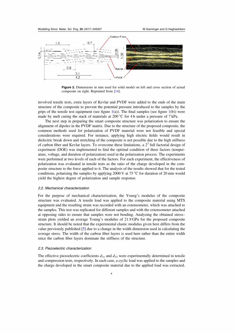
involved tensile tests, extra layers of Kevlar and PVDF were added to the ends of the mainstructure of the composite to prevent the potential pressure introduced to the samples by thegrips of the tensile test equipment (see figure 1(a)). The final samples (see figure 1(b)) weremade by melt curing the stack of materials at 200 °C for 4 h under a pressure of 7 kPa.
The next step in preparing the smart composite structure was polarization to ensure thealignment of dipoles in the PVDF matrix. Due to the structure of the proposed composite, thecommon methods used for polarization of PVDF material were not feasible and specialconsiderations were required. For instance, applying high electric fields would result indielectric break down and stretching of the composite is not possible due to the high stiffnessof carbon fiber and Kevlar layers. To overcome these limitations, a 23 full factorial design ofexperiment (DOE) was implemented to find the optimal condition of three factors (temper-ature, voltage, and duration of polarization) used in the polarization process. The experimentswere performed at two levels of each of the factors. For each experiment, the effectiveness ofpolarization was evaluated in tensile tests as the ratio of the charge developed in the com-posite structure to the force applied to it. The analysis of the results showed that for the testedconditions, polarizing the samples by applying 2000 V at 75 °C for duration of 20 min wouldyield the highest degree of polarization and sample response.
2.2. Mechanical characterization
For the purpose of mechanical characterization, the Young’s modulus of the compositestructure was evaluated. A tensile load was applied to the composite material using MTSequipment and the resulting strain was recorded with an extensometer, which was attached tothe samples. This test was replicated for different samples and with the extensometer attachedat opposing sides to ensure that samples were not bending. Analyzing the obtained stress–strain plots yielded an average Young’s modulus of 21.9 GPa for the proposed compositestructure. It should be noted that the experimental elastic modulus given here differs from thevalue previously published [5] due to a change in the width dimension used in calculating theaverage stress. The width of the carbon fiber layers is used here rather than the entire widthsince the carbon fiber layers dominate the stiffness of the structure.
2.3. Piezoelectric characterization
The effective piezoelectric coefficients d31 and d33 were experimentally determined in tensileand compression tests, respectively. In each case, a cyclic load was applied to the samples andthe charge developed in the smart composite material due to the applied load was extracted.
Figure 2. Dimensions in mm used for solid model on left and cross section of actualcomposite on right. Reprinted from [14].
Modelling Simul. Mater. Sci. Eng. 25 (2017) 045007 M Greminger and G Haghiashtiani
4
The effective piezoelectric coefficient could then be calculated as:
= =s
( ) ( ) ( )d ifor 1 or 3 , 1iQ A
3 effi
CF,electrode
Average
where Q represents the charge developed in the composite structure due to the applied load,ACF,electrode is the area of carbon fiber electrode layer, and saveragei is the average stress normalto either the 1-direction (along the structure’s length) for d31 or the 3-direction (along thestructure’s thickness) for d33. The results obtained from piezoelectric characterization of theproposed composite material are summarized in table 1. As it can be seen, the experimentalcharacterization yielded the effective d31 and d33 coefficients of - -4.36 e pC N4 1 and- -1.95pC N ,1 respectively. These values differ from those previously published [5] sincethe average stress over the entire structure is used here, where, in the previous results, only thestress in the layer between the carbon fiber layers was used. This change was made to matchthe computation of the effective piezoelectric coefficients obtained from the finite elementanalysis discussed below. Also, the d33 value is assumed to be negative here to reflect the signreported for PVDF d33 in the literature [15].
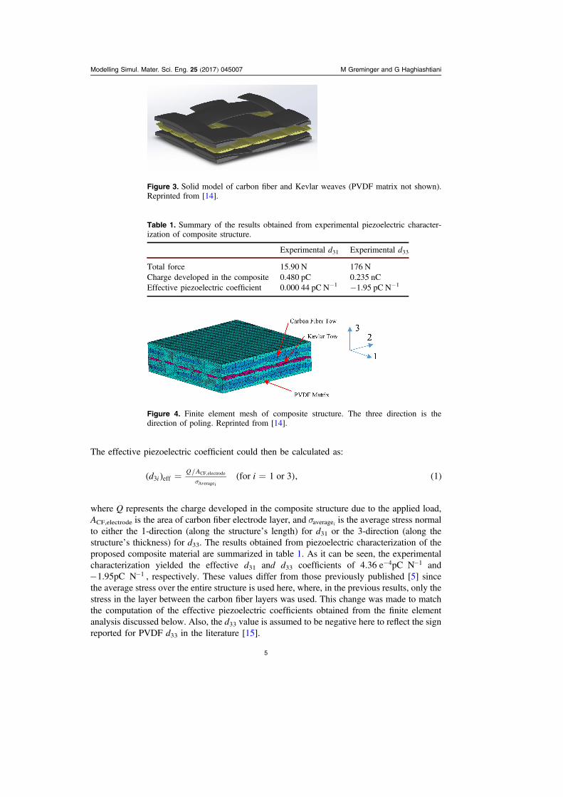
Figure 3. Solid model of carbon fiber and Kevlar weaves (PVDF matrix not shown).Reprinted from [14].
Table 1. Summary of the results obtained from experimental piezoelectric character-ization of composite structure.
Experimental d31 Experimental d33
Total force 15.90 N 176 NCharge developed in the composite 0.480 pC 0.235 nCEffective piezoelectric coefficient 0.000 44 pC N−1 −1.95 pC N−1
Figure 4. Finite element mesh of composite structure. The three direction is thedirection of poling. Reprinted from [14].
Modelling Simul. Mater. Sci. Eng. 25 (2017) 045007 M Greminger and G Haghiashtiani
5
3. Solid model and finite element mesh representation of the compositestructure
Optical cross section images of the actual smart composite structures were used to determinethe dimensions of the carbon fiber and Kevlar tows. These dimensions, along with a crosssection image of the actual composite, are shown in figure 2. Using these dimensions, a solidmodel was constructed based on the smallest repeating pattern in the carbon fiber weave. Thisresulted in a solid model with a length and width of 4.2 mm and a height of 1.08 mm. Thecarbon fiber and Kevlar components of the solid model are shown in figure 3. Figure 4 showsthe finite element mesh generated from this solid model. A tetrahedral mesh with mid-sidenodes was used.
4. Micromechanics for the electromechanical properties of the carbon fiber andKevlar tows
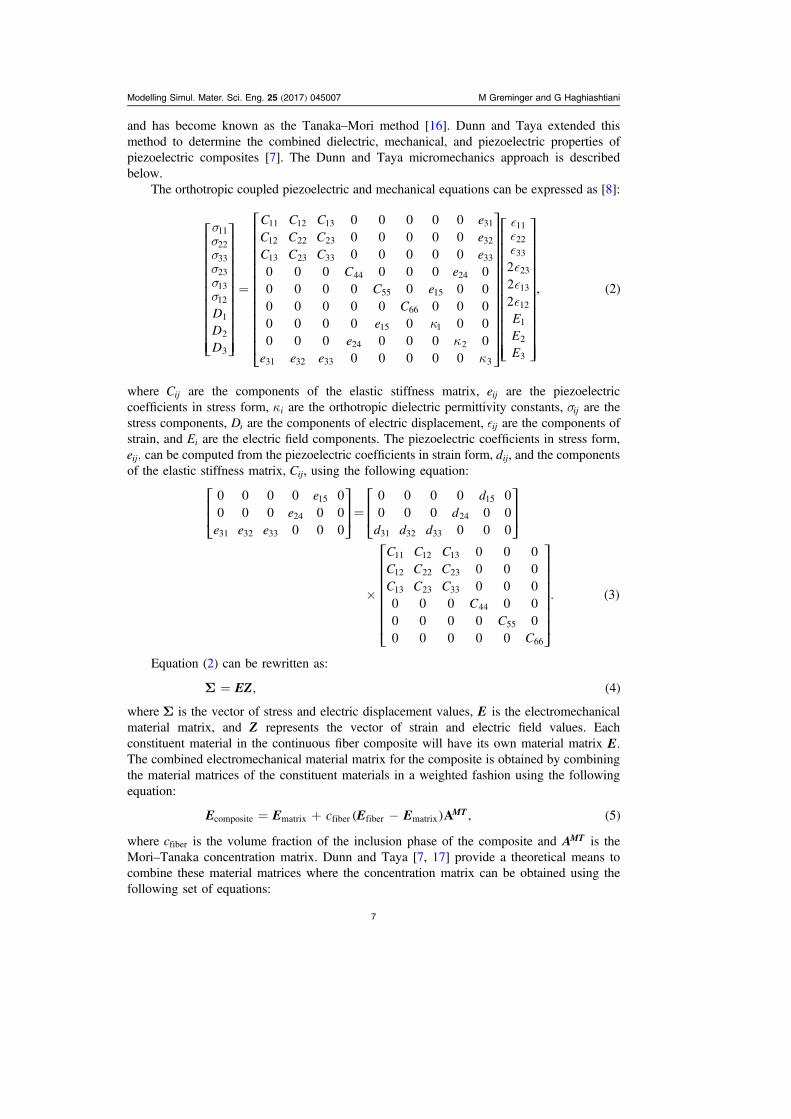
The smart composite structure is a multi-scale composite. The carbon fiber and Kevlarweaves, as shown in the previous section, are at the millimeter scale. However, the carbonfiber and Kevlar tows are composed of numerous micron scale fibers. Figure 5 shows ascanning electron microscope (SEM) image of a portion of one of the carbon fiber towsshowing the numerous fibers surrounded by PVDF matrix that make up each of the tows.
One approach to model the properties for each of the tows would be to include thegeometry of the individual carbon and Kevlar fibers in the finite element model. However,this would result in a finite element mesh with more elements than could be solved in areasonable amount of time since the Kevlar fibers are 15 μm in diameter and the carbon fibersare 6 μm in diameter, both of which are three orders of magnitude smaller than the carbonfiber weave. For this reason, the electrical, mechanical, and piezoelectric properties will becomputed numerically based on the electromechanical properties of the constituent materials.Both the micromechanics approach proposed by Dunn and Taya [7] and a finite elementapproach to computing the electromechanical properties of the tows will be explored in thissection.
4.1. The dunn and taya micromechanics approach
An efficient method to numerically determine the effective elastic moduli for compositestructures with high concentrations of inclusions was originally proposed by Tanaka and Mori
Figure 5. SEM image of carbon fiber tow cross section on left and manually placed dotsrepresenting fiber locations on right. The average carbon fiber diameter is 5.9 μm.Reprinted from [14].
Modelling Simul. Mater. Sci. Eng. 25 (2017) 045007 M Greminger and G Haghiashtiani
6
and has become known as the Tanaka–Mori method [16]. Dunn and Taya extended thismethod to determine the combined dielectric, mechanical, and piezoelectric properties ofpiezoelectric composites [7]. The Dunn and Taya micromechanics approach is describedbelow.
The orthotropic coupled piezoelectric and mechanical equations can be expressed as [8]:
ssssss
kk
k
=
⎡
⎣
⎢⎢⎢⎢⎢⎢⎢⎢⎢
⎤
⎦
⎥⎥⎥⎥⎥⎥⎥⎥⎥
⎡
⎣
⎢⎢⎢⎢⎢⎢⎢⎢⎢⎢
⎤
⎦
⎥⎥⎥⎥⎥⎥⎥⎥⎥⎥
⎡
⎣
⎢⎢⎢⎢⎢⎢⎢⎢⎢⎢
⎤
⎦
⎥⎥⎥⎥⎥⎥⎥⎥⎥⎥
( )
DDD
C C C eC C C eC C C e
C eC e
Ce
ee e e
EEE
0 0 0 0 00 0 0 0 00 0 0 0 0
0 0 0 0 0 0 00 0 0 0 0 0 00 0 0 0 0 0 0 00 0 0 0 0 0 00 0 0 0 0 0 0
0 0 0 0 0
222
, 2
11
22
33
23
13
12
1
2
3
11 12 13 31
12 22 23 32
13 23 33 33
44 24
55 15
66
15 1
24 2
31 32 33 3
11
22
33
23
13
12
1
2
3
where Cij are the components of the elastic stiffness matrix, eij are the piezoelectriccoefficients in stress form, ki are the orthotropic dielectric permittivity constants, sij are thestress components, Di are the components of electric displacement, ij are the components ofstrain, and Ei are the electric field components. The piezoelectric coefficients in stress form,e ,ij can be computed from the piezoelectric coefficients in strain form, d ,ij and the componentsof the elastic stiffness matrix, C ,ij using the following equation:
=
´
⎡
⎣⎢⎢
⎤
⎦⎥⎥
⎡
⎣⎢⎢
⎤
⎦⎥⎥
⎡
⎣
⎢⎢⎢⎢⎢⎢
⎤
⎦
⎥⎥⎥⎥⎥⎥( )
ee
e e e
dd
d d d
C C CC C CC C C
CC
C
0 0 0 0 00 0 0 0 0
0 0 0
0 0 0 0 00 0 0 0 0
0 0 0
0 0 00 0 00 0 0
0 0 0 0 00 0 0 0 00 0 0 0 0
. 3
15
24
31 32 33
15
24
31 32 33
11 12 13
12 22 23
13 23 33
44
55
66
Equation (2) can be rewritten as:
S = ( )EZ, 4
where S is the vector of stress and electric displacement values, E is the electromechanicalmaterial matrix, and Z represents the vector of strain and electric field values. Eachconstituent material in the continuous fiber composite will have its own material matrix E.The combined electromechanical material matrix for the composite is obtained by combiningthe material matrices of the constituent materials in a weighted fashion using the followingequation:
= + -( ) ( )E E E Ec A , 5MTcomposite matrix fiber fiber matrix
where cfiber is the volume fraction of the inclusion phase of the composite and AMT is theMori–Tanaka concentration matrix. Dunn and Taya [7, 17] provide a theoretical means tocombine these material matrices where the concentration matrix can be obtained using thefollowing set of equations:
Modelling Simul. Mater. Sci. Eng. 25 (2017) 045007 M Greminger and G Haghiashtiani
7
= + -- -[ ( )] ( )A I SE E E , 6dilmatrix
1fiber matrix
1
= + -[ ] ( )A A I Ac c , 7MT dilmatrix fiber
dil 1
where Adil is the dilute approximation of the concentration matrix, I is the identity matrix, andS is the matrix representation of the Eshelby’s constraint tensor for an ellipsoid occlusion.The constraint matrix S has been extended by Dunn and Taya to consider the coupledelectromechanical behavior required for piezoelectric composite materials. The constrainttensor can be expressed as the following integrals over the unit sphere [17]:
ò
ò=
+ =
=
p z
p z
=
=
⎧⎨⎪⎩⎪
[ ( ) ( )] ( )
( ) ( )( )∣ ∣
∣ ∣
z z z
z zS
G G S M
G S M
d , 1, 2, 3,
d , 4,8MnAb
a a a
z mJin nJim
a a a
z Jin
8 1
1
4 1
14
1 2 33
1 2 33
where =∣ ∣z 1 is the surface of the unit sphere, and:
z = + +[ ] ( )a z a z a z , 912
12
22
22
32
32 1
2
where a ,1 a ,2 and a3 are the lengths of the semi-axes of the ellipsoidal inclusion, and:
= -( ) ( ) ( )z zG z z K , 10MJin i n MJ1
where:
= ( )K E z z . 11MJ iJMn i n
Equations (8), (10) and (11) make use of standard indicial notation, where repeatedindices indicate summation, with the addition that lower case indices take on the values 1–3and upper case indices take on the values 1–4. Note that the constraint tensor SMnAb can beevaluated for a continuous fiber inclusion by taking the limit as one of a ,1 a ,2 or a3 tend toinfinity. For the continuous fiber composite materials evaluated here, the 1-direction is takenas the fiber direction, so the integrals in (8) are evaluated for the case when a1 tends towardsinfinity. In addition, for the case of continuous fiber inclusions, the integrals in (8) cannot beevaluated analytically. The python function quad from the library mpmath was used tonumerically evaluate these integrals [18].
4.2. The finite element micromechanics approach
In order to validate the Dunn and Taya method for the continuous fiber smart compositematerials used in this work, the results of computing the tow properties using (5)–(11) were
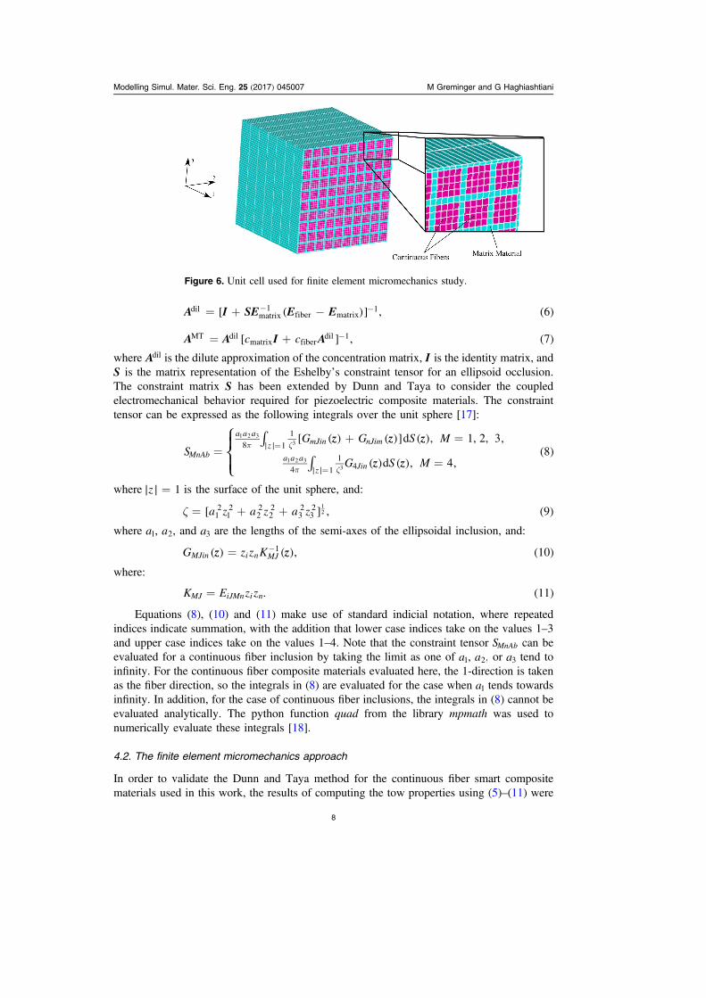
Figure 6. Unit cell used for finite element micromechanics study.
Modelling Simul. Mater. Sci. Eng. 25 (2017) 045007 M Greminger and G Haghiashtiani
8
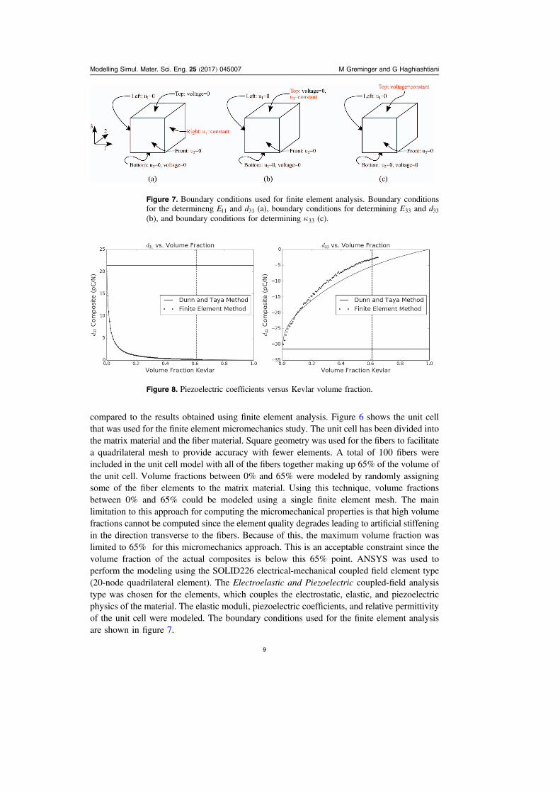
compared to the results obtained using finite element analysis. Figure 6 shows the unit cellthat was used for the finite element micromechanics study. The unit cell has been divided intothe matrix material and the fiber material. Square geometry was used for the fibers to facilitatea quadrilateral mesh to provide accuracy with fewer elements. A total of 100 fibers wereincluded in the unit cell model with all of the fibers together making up 65% of the volume ofthe unit cell. Volume fractions between 0% and 65% were modeled by randomly assigningsome of the fiber elements to the matrix material. Using this technique, volume fractionsbetween 0% and 65% could be modeled using a single finite element mesh. The mainlimitation to this approach for computing the micromechanical properties is that high volumefractions cannot be computed since the element quality degrades leading to artificial stiffeningin the direction transverse to the fibers. Because of this, the maximum volume fraction waslimited to 65% for this micromechanics approach. This is an acceptable constraint since thevolume fraction of the actual composites is below this 65% point. ANSYS was used toperform the modeling using the SOLID226 electrical-mechanical coupled field element type(20-node quadrilateral element). The Electroelastic and Piezoelectric coupled-field analysistype was chosen for the elements, which couples the electrostatic, elastic, and piezoelectricphysics of the material. The elastic moduli, piezoelectric coefficients, and relative permittivityof the unit cell were modeled. The boundary conditions used for the finite element analysisare shown in figure 7.
Figure 7. Boundary conditions used for finite element analysis. Boundary conditionsfor the determineng E11 and d31 (a), boundary conditions for determining E33 and d33
(b), and boundary conditions for determining k33 (c).
Figure 8. Piezoelectric coefficients versus Kevlar volume fraction.
Modelling Simul. Mater. Sci. Eng. 25 (2017) 045007 M Greminger and G Haghiashtiani
9
4.3. Micromechanics results
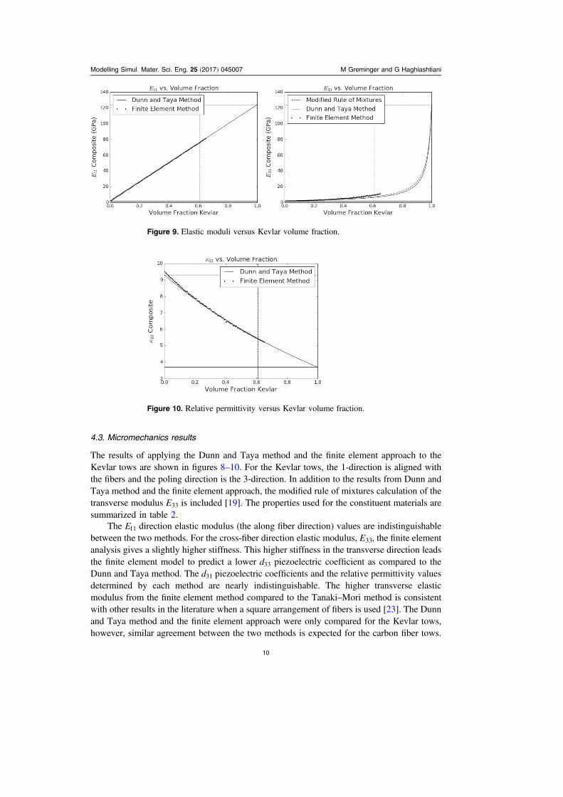
The results of applying the Dunn and Taya method and the finite element approach to theKevlar tows are shown in figures 8–10. For the Kevlar tows, the 1-direction is aligned withthe fibers and the poling direction is the 3-direction. In addition to the results from Dunn andTaya method and the finite element approach, the modified rule of mixtures calculation of thetransverse modulus E33 is included [19]. The properties used for the constituent materials aresummarized in table 2.
The E11 direction elastic modulus (the along fiber direction) values are indistinguishablebetween the two methods. For the cross-fiber direction elastic modulus, E ,33 the finite elementanalysis gives a slightly higher stiffness. This higher stiffness in the transverse direction leadsthe finite element model to predict a lower d33 piezoelectric coefficient as compared to theDunn and Taya method. The d31 piezoelectric coefficients and the relative permittivity valuesdetermined by each method are nearly indistinguishable. The higher transverse elasticmodulus from the finite element method compared to the Tanaki–Mori method is consistentwith other results in the literature when a square arrangement of fibers is used [23]. The Dunnand Taya method and the finite element approach were only compared for the Kevlar tows,however, similar agreement between the two methods is expected for the carbon fiber tows.
Figure 9. Elastic moduli versus Kevlar volume fraction.
Figure 10. Relative permittivity versus Kevlar volume fraction.
Modelling Simul. Mater. Sci. Eng. 25 (2017) 045007 M Greminger and G Haghiashtiani
10
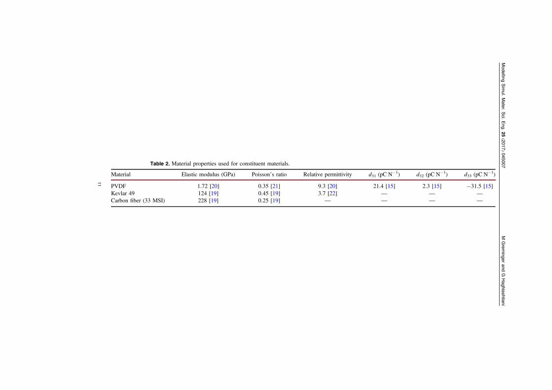
Table 2. Material properties used for constituent materials.
Material Elastic modulus (GPa) Poisson’s ratio Relative permittivity d31 (pC N−1) d32 (pC N−1) d33 (pC N−1)
PVDF 1.72 [20] 0.35 [21] 9.3 [20] 21.4 [15] 2.3 [15] −31.5 [15]Kevlar 49 124 [19] 0.45 [19] 3.7 [22] — — —
Carbon fiber (33 MSI) 228 [19] 0.25 [19] — — — —
Modelling
Sim
ul.Mater.
Sci.
Eng.
25(2017)
045007M
Grem
ingerand
GHaghiashtiani
11
Given the good agreement between the Dunn and Taya method and the finite elementapproach for computing the composite tow electromechanical properties, the Dunn and Tayamethod will be used to compute both the Kevlar and carbon fiber tow properties for the resultspresented in section 5.
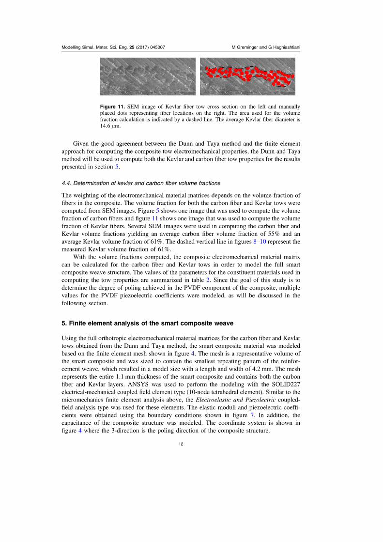
4.4. Determination of kevlar and carbon fiber volume fractions
The weighting of the electromechanical material matrices depends on the volume fraction offibers in the composite. The volume fraction for both the carbon fiber and Kevlar tows werecomputed from SEM images. Figure 5 shows one image that was used to compute the volumefraction of carbon fibers and figure 11 shows one image that was used to compute the volumefraction of Kevlar fibers. Several SEM images were used in computing the carbon fiber andKevlar volume fractions yielding an average carbon fiber volume fraction of 55% and anaverage Kevlar volume fraction of 61%. The dashed vertical line in figures 8–10 represent themeasured Kevlar volume fraction of 61%.
With the volume fractions computed, the composite electromechanical material matrixcan be calculated for the carbon fiber and Kevlar tows in order to model the full smartcomposite weave structure. The values of the parameters for the constituent materials used incomputing the tow properties are summarized in table 2. Since the goal of this study is todetermine the degree of poling achieved in the PVDF component of the composite, multiplevalues for the PVDF piezoelectric coefficients were modeled, as will be discussed in thefollowing section.
5. Finite element analysis of the smart composite weave
Using the full orthotropic electromechanical material matrices for the carbon fiber and Kevlartows obtained from the Dunn and Taya method, the smart composite material was modeledbased on the finite element mesh shown in figure 4. The mesh is a representative volume ofthe smart composite and was sized to contain the smallest repeating pattern of the reinfor-cement weave, which resulted in a model size with a length and width of 4.2 mm. The meshrepresents the entire 1.1 mm thickness of the smart composite and contains both the carbonfiber and Kevlar layers. ANSYS was used to perform the modeling with the SOLID227electrical-mechanical coupled field element type (10-node tetrahedral element). Similar to themicromechanics finite element analysis above, the Electroelastic and Piezolectric coupled-field analysis type was used for these elements. The elastic moduli and piezoelectric coeffi-cients were obtained using the boundary conditions shown in figure 7. In addition, thecapacitance of the composite structure was modeled. The coordinate system is shown infigure 4 where the 3-direction is the poling direction of the composite structure.
Figure 11. SEM image of Kevlar fiber tow cross section on the left and manuallyplaced dots representing fiber locations on the right. The area used for the volumefraction calculation is indicated by a dashed line. The average Kevlar fiber diameter is14.6 μm.
Modelling Simul. Mater. Sci. Eng. 25 (2017) 045007 M Greminger and G Haghiashtiani
12
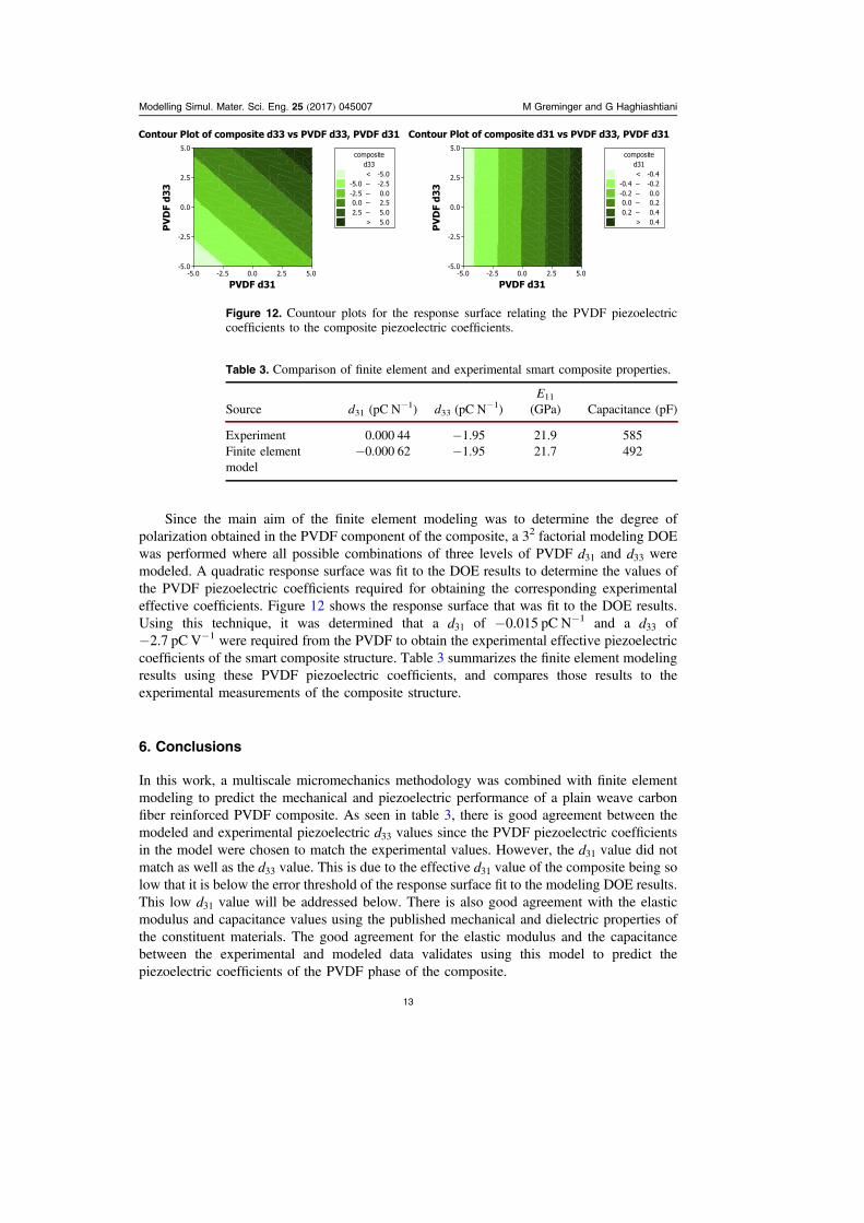
Since the main aim of the finite element modeling was to determine the degree ofpolarization obtained in the PVDF component of the composite, a 32 factorial modeling DOEwas performed where all possible combinations of three levels of PVDF d31 and d33 weremodeled. A quadratic response surface was fit to the DOE results to determine the values ofthe PVDF piezoelectric coefficients required for obtaining the corresponding experimentaleffective coefficients. Figure 12 shows the response surface that was fit to the DOE results.Using this technique, it was determined that a d31 of −0.015 pC N−1 and a d33 of−2.7 pC V−1 were required from the PVDF to obtain the experimental effective piezoelectriccoefficients of the smart composite structure. Table 3 summarizes the finite element modelingresults using these PVDF piezoelectric coefficients, and compares those results to theexperimental measurements of the composite structure.
6. Conclusions
In this work, a multiscale micromechanics methodology was combined with finite elementmodeling to predict the mechanical and piezoelectric performance of a plain weave carbonfiber reinforced PVDF composite. As seen in table 3, there is good agreement between themodeled and experimental piezoelectric d33 values since the PVDF piezoelectric coefficientsin the model were chosen to match the experimental values. However, the d31 value did notmatch as well as the d33 value. This is due to the effective d31 value of the composite being solow that it is below the error threshold of the response surface fit to the modeling DOE results.This low d31 value will be addressed below. There is also good agreement with the elasticmodulus and capacitance values using the published mechanical and dielectric properties ofthe constituent materials. The good agreement for the elastic modulus and the capacitancebetween the experimental and modeled data validates using this model to predict thepiezoelectric coefficients of the PVDF phase of the composite.
Figure 12. Countour plots for the response surface relating the PVDF piezoelectriccoefficients to the composite piezoelectric coefficients.
Table 3. Comparison of finite element and experimental smart composite properties.
Source d31 (pC N−1) d33 (pC N−1)E11
(GPa) Capacitance (pF)
Experiment 0.000 44 −1.95 21.9 585Finite elementmodel
−0.000 62 −1.95 21.7 492
Modelling Simul. Mater. Sci. Eng. 25 (2017) 045007 M Greminger and G Haghiashtiani
13
Through finite element modeling of the smart composite structure, it was found that thepolarization process obtains a PVDF component d31 value of −0.015 pC N−1 and a d33 valueof −2.7 pC N−1. The d31 value obtained is about three orders of magnitude smaller thanwould be expected for a fully polarized PVDF material and the d33 value is about one order ofmagnitude smaller than would be expected for a fully polarized PVDF material (see table 2for typical d31 and d33 values for a fully polarized PVDF material). This indicates that there isopportunity to increase the sensitivity of the proposed smart composite structure by at least anorder of magnitude by improving the polarization process. Also, the disproportionally low d31
value indicates that the crystal structure of the PVDF phase may not match the crystalstructure normally obtained in polarized PVDF structures. An investigation of the crystallinestructure will be pursued in future work to characterize the polarization of the PVDF in asimilar fashion to what has been done in other studies [24].
Acknowledgments
This work was supported in part by the Swenson College of Science and Engineering at theUniversity of Minnesota Duluth and by Grant-in-Aid funding from the University ofMinnesota.
References
[1] Staszewski W, Boller C and Tomlinson G R 2004 Health Monitoring of Aerospace Structures:Smart Sensor Technologies and Signal Processing (New York: Wiley)
[2] Giurgiutiu V and Soutis C 2012 Enhanced composites integrity through structural healthmonitoring Appl. Compos. Mater. 19 813–29
[3] Lynch J P and Loh K J 2006 A summary review of wireless sensors and sensor networks forstructural health monitoring Shock Vib. Dig. 38 91–130
[4] Swartz R A, Lynch J P, Zerbst S, Sweetman B and Rolfes R 2010 Structural monitoring of windturbines using wireless sensor networks Smart Struct. Syst. 6 183–96
[5] Haghiashtiani G and Greminger M A 2015 Fabrication, polarization, and characterization ofPVDF matrix composites for integrated structural load sensing Smart Mater. Struct. 24 045038
[6] Turik A V, Topolov V Y and Aleshin V I 2000 On a correlation between remanent polarizationand piezoelectric coefficients of perovskite-type ferroelectric ceramics J. Phys. D: Appl. Phys.33 738
[7] Dunn M L and Taya M 1993 An analysis of piezoelectric composite materials containingellipsoidal inhomogeneities Proc.: Math. Phys. Sci. 443 265–87
[8] Odegard G M 2004 Constitutive modeling of piezoelectric polymer composites Acta Mater. 525315–30
[9] Chan H L W and Unsworth J 1989 Simple model for piezoelectric ceramic/polymer 1–3composites used in ultrasonic transducer applications IEEE Trans. Ultrason. Ferroelectr. Freq.Control 36 434–41
[10] Lin C-H and Muliana A 2013 Micromechanics models for the effective nonlinear electro-mechanical responses of piezoelectric composites Acta Mech. 224 1471–92
[11] Ho C H, Poon Y M and Shin F G 2006 New explicit formulas for the effective piezoelectriccoefficients of binary 0–3 composites J. Electroceramics 16 283–8
[12] Tan P, Tong L and Steven G P 1997 Modelling for predicting the mechanical properties of textilecomposites—a review Composites A 28 903–22
[13] Barbero E J, Trovillion J, Mayugo J A and Sikkil K K 2006 Finite element modeling of plainweave fabrics from photomicrograph measurements Compos. Struct. 73 41–52
[14] Greminger M and Haghiashtiani G 2015 Finite element modeling of PVDF matrix carbon fibercomposites Int. Workshop on Structural Health Monitoring (IWSHM 2015) (Stanford,California)
Modelling Simul. Mater. Sci. Eng. 25 (2017) 045007 M Greminger and G Haghiashtiani
14
[15] Nalwa H S 1995 Ferroelectric Polymers: Chemistry: Physics, and Applications (Boca Raton, FL:CRC Press)
[16] Mori T and Tanaka K 1973 Average stress in matrix and average elastic energy of materials withmisfitting inclusions Acta Metall. 21 571–4
[17] Dunn M L and Taya M 1993 Micromechanics predictions of the effective electroelastic moduli ofpiezoelectric composites Int. J. Solids Struct. 30 161–75
[18] Johansson F et al 2014 mpmath: a python library for arbitrary-precision floating-point arithmetic(version 0.19)http://mpmath.org/
[19] Laszlo G S S and Kollar P 2009 Mechanics of Composite Structures (Cambridge: CambridgeUniversity Pres)
[20] ‘Professional Plastics, PVDF Film—Material Data Sheet’: http://professionalplastics.com/professionalplastics/content/PVDFFilmDataSheet.doc (Accessed: 31-May-2015)
[21] Furukawa T, Wen J X, Suzuki K, Takashina Y and Date M 1984 Piezoelectricity andpyroelectricity in vinylidene fluoride/trifluoroethylene copolymers J. Appl. Phys. 56 829–34
[22] Minges M L 1989 Electronic Materials Handbook: Packaging vol 1 (Materials Park, OH: ASMInternational)
[23] Benedikt B, Rupnowski P and Kumosa M 2003 Visco-elastic stress distributions and elasticproperties in unidirectional composites with large volume fractions of fibers Acta Mater. 513483–93
[24] Riosbaas M T, Loh K J, O’Bryan G and Loyola B R 2014 In situ phase change characterization ofPVDF thin films using raman spectroscopy SPIE Smart Structures and Materials +Nondestructive Evaluation and Health Monitoring p 90610Z
Modelling Simul. Mater. Sci. Eng. 25 (2017) 045007 M Greminger and G Haghiashtiani
15


![Polyvinylidene Difluoride Piezoelectric Electrospun ...downloads.hindawi.com/journals/jnm/2018/8164185.pdf · properties such as PZT, PVC, nylon 11, and PVDF [7–9]. But due to PVDF](https://static.fdocuments.us/doc/165x107/5f32d9e4df8bf02cb255d864/polyvinylidene-difluoride-piezoelectric-electrospun-properties-such-as-pzt.jpg)