Multipurpose Radio for Railways. Construction and Applications
4
ADVANCES IN ELECTRONICS AND TELECOMMUNICATIONS,VOL. 1, NO. 2, NOVEMBER 2010 3 Multipurpose Radio for Railways. Construction and Applications Jerzy Kasperek, Andrzej Nikoniuk, and Pawel Rajda Abstract—This paper provides information on the construction and presents experience from the “Koliber” project: a modern multipurpose radio system for railways. The radio equipment is produced by Radionika Ltd., and was designed in cooperation with Department of Electronics, AGH University of Science and Technology. Discussed here are system architecture, technical and functional parameters, and innovative radio system applications possible thanks to its innovatory construction. Index Terms—VHF railway radio, GSM-R I. I NTRODUCTION “ K OLIBER” is a modern solution for radio communica- tion, designed exclusively for railway needs. The device works as a mobile set in double-cabin locomotives of all types and in any other rail vehicles. The stationary version of the radio is intended to work as a base station, operated by the railway dispatcher. The device provides radio connections of all types in radio networks operated by railway companies, using VHF 150MHz band. The device provides a specific signaling used in Polish railways: tone selected calls (Zew1, Zew3) and emergency train stop protocol [1], [2]. Among the mandatory functions presented above, the solution offers more advanced functions available in contemporary radio communication. In particular, the device enables a range of functions including selective call signaling (SelCall), CTCSS/DCS encoding and decoding, modem data transmission, and GPS navigation. Furthermore, the architecture and technology of the equip- ment allow also using the device in other communication network standards (including GSM and GSM-R). Besides the obvious economic benefits (single device supporting multiple communication systems), this solution significantly simplifies the operation of radio for railway vehicle drivers and dispatch- ers. “Koliber” is a solution that not only serves the needs of current users of the railway network but also ensures the operation of equipment after modernization of the network and during switching to a new digital communication standard. The device is fully compatible with mounting and connectors currently used in vehicles and dispatcher desks. The dimen- sions and solutions of the device were designed to enable quick assembly and setup with use of the existing wiring and fixtures. II. RADIO SET ARCHITECTURE Fig. 1 presents the architecture of the radio set version designed for the double-cabin locomotives. Both cabins are Fig. 1. “Koliber” radio system architecture. equipped with a manipulator (DMI – Driver Machine In- terface). Each DMI is connected with an intelligent switch module which commutes signals to the radio module. The switch module may optionally be equipped with a GSM engine to carry on voice communication through the mobile phone network of any operator and/or to transmit GPRS messages, including the status, geographical coordinates, and parameters of the locomotive (e.g. the consumption of fuel in combustion locomotives). The entire set is powered through a universal DC/DC converter, working within a wide range of voltage (15... 212V). Single-cabin locomotive sets have only one DMI mounted, while stationary sets feature an AC/DC power supply mounted instead of the DC/DC converter. Moreover, the open archi- tecture of the device enables integration of any ready-to-use GSM-R external modules [3]. To date, successful integration with certified PortBox Ultralight GSM-R module of HFWK (formerly Kapsch) was performed. III. DRIVER-MACHINE I NTERFACE MODULE The DMI (Driver-Machine Interface) module performs the role of the user’s interface radio. Its main operational elements include: • high resolution graphic LCD display with backlight, • contextually illuminated numeric and functional keypad, • “RadioStop” button being a part of the emergency train stop system, • set of signaling LEDs, • microphone with the PTT (Push To Talk) key, • speaker, • 1-Wire interface for identification/authentication. The block diagram of the DMI module is presented in Fig. 2. It is a typical microcontroller application based on a 8-bit Atmel RISC ATmega128 device. The DMI features a
Transcript of Multipurpose Radio for Railways. Construction and Applications
ADVANCES IN ELECTRONICS AND TELECOMMUNICATIONS, VOL. 1, NO. 2, NOVEMBER 2010 3
Multipurpose Radio for Railways. Construction and
ApplicationsJerzy Kasperek, Andrzej Nikoniuk, and Paweł Rajda
Abstract—This paper provides information on the constructionand presents experience from the “Koliber” project: a modernmultipurpose radio system for railways. The radio equipment isproduced by Radionika Ltd., and was designed in cooperationwith Department of Electronics, AGH University of Science andTechnology. Discussed here are system architecture, technical andfunctional parameters, and innovative radio system applicationspossible thanks to its innovatory construction.
Index Terms—VHF railway radio, GSM-R
I. INTRODUCTION
“
KOLIBER” is a modern solution for radio communica-
tion, designed exclusively for railway needs. The device
works as a mobile set in double-cabin locomotives of all types
and in any other rail vehicles. The stationary version of the
radio is intended to work as a base station, operated by the
railway dispatcher.
The device provides radio connections of all types in radio
networks operated by railway companies, using VHF 150MHz
band. The device provides a specific signaling used in Polish
railways: tone selected calls (Zew1, Zew3) and emergency
train stop protocol [1], [2]. Among the mandatory functions
presented above, the solution offers more advanced functions
available in contemporary radio communication. In particular,
the device enables a range of functions including selective
call signaling (SelCall), CTCSS/DCS encoding and decoding,
modem data transmission, and GPS navigation.
Furthermore, the architecture and technology of the equip-
ment allow also using the device in other communication
network standards (including GSM and GSM-R). Besides the
obvious economic benefits (single device supporting multiple
communication systems), this solution significantly simplifies
the operation of radio for railway vehicle drivers and dispatch-
ers. “Koliber” is a solution that not only serves the needs
of current users of the railway network but also ensures the
operation of equipment after modernization of the network and
during switching to a new digital communication standard.
The device is fully compatible with mounting and connectors
currently used in vehicles and dispatcher desks. The dimen-
sions and solutions of the device were designed to enable quick
assembly and setup with use of the existing wiring and fixtures.
II. RADIO SET ARCHITECTURE
Fig. 1 presents the architecture of the radio set version
designed for the double-cabin locomotives. Both cabins are
Fig. 1. “Koliber” radio system architecture.
equipped with a manipulator (DMI – Driver Machine In-
terface). Each DMI is connected with an intelligent switch
module which commutes signals to the radio module. The
switch module may optionally be equipped with a GSM engine
to carry on voice communication through the mobile phone
network of any operator and/or to transmit GPRS messages,
including the status, geographical coordinates, and parameters
of the locomotive (e.g. the consumption of fuel in combustion
locomotives).
The entire set is powered through a universal DC/DC
converter, working within a wide range of voltage (15... 212V).
Single-cabin locomotive sets have only one DMI mounted,
while stationary sets feature an AC/DC power supply mounted
instead of the DC/DC converter. Moreover, the open archi-
tecture of the device enables integration of any ready-to-use
GSM-R external modules [3]. To date, successful integration
with certified PortBox Ultralight GSM-R module of HFWK
(formerly Kapsch) was performed.
III. DRIVER-MACHINE INTERFACE MODULE
The DMI (Driver-Machine Interface) module performs the
role of the user’s interface radio. Its main operational elements
include:
• high resolution graphic LCD display with backlight,
• contextually illuminated numeric and functional keypad,
• “RadioStop” button being a part of the emergency train
stop system,
• set of signaling LEDs,
• microphone with the PTT (Push To Talk) key,
• speaker,
• 1-Wire interface for identification/authentication.
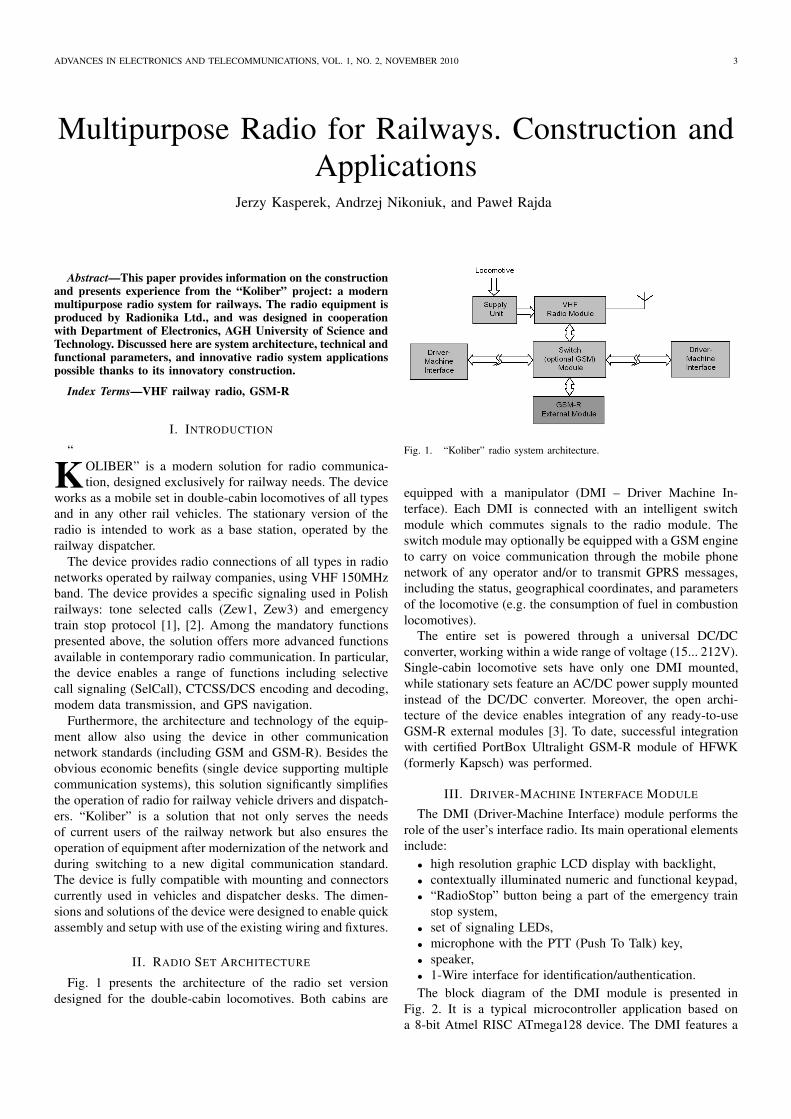
The block diagram of the DMI module is presented in
Fig. 2. It is a typical microcontroller application based on
a 8-bit Atmel RISC ATmega128 device. The DMI features a
4 ADVANCES IN ELECTRONICS AND TELECOMMUNICATIONS, VOL. 1, NO. 2, NOVEMBER 2010
Fig. 2. Driver Machine Interface block diagram.
large and clear graphic LCD display unit with resolution of
240×64 pixels to present the current state of the whole radio
set. The display presents also contextual description of the
keyboard functions. The meaning of particular keys depends
on the menu selected, and contextual illumination facilitates
their operation further. 1-Wire contact devices are used for
access authorization and radio operator log-in & log-out.
Communication with other modules of the set is performed
via RS422 bus, while the radio voice is sent as analogue.
IV. SWITCH MODULE
The primary task of the switch module is commutation of
signals between the radio module and the active DMI in one
of the two locomotive cabins. This module was designed and
developed as a natural replacement for the mechanical switch
used before in most locomotives in Poland [4]. The switch
module can optionally be equipped with the GSM Motorola
G24 engine. This solution enables concurrent usage of the
audio and data GSM services parallel to standard work in the
VHF band. This allows using emergency calls as well as SMS.
What is more, once a GPS module has been installed, it
is also possible to transfer train location data via the GPRS
data link. The GPRS network link is a convenient medium
for transmission of all kinds of status messages between the
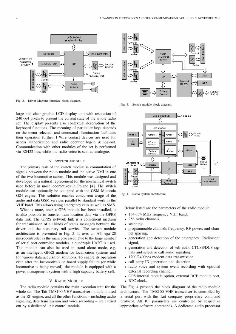
driver and the stationary rail service. The switch module
architecture is presented in Fig. 3. It uses an ATmega128
microcontroller as the main processor. Due to the large number
of serial port controlled modules, a quadruple UART is used.
This module can also be used in stand alone mode, e.g.
as an intelligent GPRS modem for localization systems and
for various data acquisition solutions. To enable its operation
even after the locomotive’s on-board supply failure (or while
locomotive is being moved), the module is equipped with a
power management system with a high capacity battery cell.
V. RADIO MODULE
The radio module contains the main execution unit for the
whole set. The Tait TM8100 VHF transceiver module is used
as the RF engine, and all the other functions – including audio
signaling, data transmission and voice recording – are carried
out by a dedicated unit control module.
Fig. 3. Switch module block diagram.
Fig. 4. Radio system architecture.
Below listed are the parameters of the radio module:
• 134-174 MHz frequency VHF band,
• 256 radio channels,
• scanning,
• programmable channels frequency, RF power, and chan-
nel spacing,
• generation and detection of the emergency “Radiostop”
signal,
• generation and detection of sub-audio CTCSS/DCS sig-
nals and selective call audio signaling,
• 1200/2400bps modem data transmission,
• call party ID generation and detection,
• radio voice and system event recording with optional
external recording channel,
• GPS internal module option, external DCF module port,
• RTC clock.
The Fig. 4 presents the block diagram of the radio module
architecture. The TM8100 VHF transceiver is controlled by
a serial port with the Tait company proprietary command
protocol. All RF parameters are controlled by respective
appropriate software commands. A dedicated audio processor

KASPEREK et al.: MULTIPURPOSE RADIO FOR RAILWAYS.CONSTRUCTION AND APPLICATIONS 5
Fig. 5. “Koliber” GPS System architecture.
Fig. 6. “Qguar Qpilot” localization window.
CMX7041 chip from CML is used for all audio and sub-audio
signaling, and also for modem transmission. In Poland, the call
party ID signals are transmitted as modem messages.
The radio module is controlled by the same type of micro-
controller (ATmega128 from Atmel). However, due to a signif-
icant need of hardware resources, the remaining module archi-
tecture is implemented in 200k gates FPGA Spartan3 device
from Xilinx. The main subsystem implemented in FPGA is
the Secure Digital flash memory card host controller. SD cards
are used as the archive repository for voice and event records.
To enable quick archive content reading without removing the
SD card, an SD controller was designed to work in a high-
speed parallel (4-bit data bus) mode with troughput exceeding
10MB/s. In addition, the FPGA implements an interface to a
USB 2.0 controller, two UARTs (one for communication with
the TM8100 VHF transceiver and the other for the service),
two CVSD codec drivers (one for recording audio from the
radio set; i.e. VHF GSM calls, the other for an optional
external voice recorder), external data memory interface for the
microcontroller, and the authentication subsystem based on a
hardware implementation of Blowfish cryptographic algorithm
with external “1-Wire” ID device.
The module uses a small backup battery for the real-time
clock device. Time synchronization is provided by the GPS
engine, which – in the case of desktop solutions – may be
replaced with an external DCF77 receiver.
Fig. 7. Real-time locomotive cockpit visualization.
Fig. 8. Architecture of DSR radio dispatcher system.
VI. SYSTEM FIRMWARE
Microcontrollers software was written in C language in the
IAR AVR environment, and the FPGA project was created
with VHDL.
The intelligent switch module with GPRS option uses UIP
TCP/IP freeware stack [5]. The web server and client ensure
HTTP support for the “post” and “get” commands. When
the external monitoring device is connected, one can use
the proprietary protocol to query the module for numerous
parameters of the locomotive and localization. There is also
an option to remotely change any EEPROM configuration
memory content, e.g. the APN name and other GPRS network
connection parameters.
6 ADVANCES IN ELECTRONICS AND TELECOMMUNICATIONS, VOL. 1, NO. 2, NOVEMBER 2010
Fig. 9. GUI of DSR radio dispatcher system.
Fig. 10. GIS RSSI data report.
The AVR bootloader feature may be used to change any
module microcontroller program memory and/or the FPGA
configuration memory content, which facilitates firmware up-
grades.
All radio parameters can be set up using a dedicated
software connected to the DMI module service RS232 port.
VII. APPLICATIONS AND EXPERIENCES
Based on the referred solution, some interesting applica-
tions of the radio set have been implemented. Their number
includes:
• train localization and locomotive parameters monitoring
system,
• DSR dispatcher system – remotely controlled VHF base
station sets for railway main tracks,
• G.sHDSL modem for the radio remote controll,
• GIS RSSI measurement system for railway tracks.
Presented below is a selection of screens and diagrams of the
aplications mentioned.
Fig. 5 presents “Qguar Qpilot” fleet management system
architecture from Quantum Software S.A. The “Koliber” radio
set sends localization data from GPS via the GPRS link to the
company’s APN GSM infrastracture. Fig. 6 presents a sample
GUI window from the application.
Fig. 7 presents real time visualization of the locomotive
parameters from the “Koliber” switch module, connected to
the CL400 module of the locomotive monitoring unit (manu-
factured by ZEPWN).
Fig. 9 presents an architecture of the DSR dispatcher radio
system, which consists of several radio base stations controlled
by dispatchers from the Local Control Center. Each base
station includes up to 4 radios, along with a service DMI
module and a control unit. Base stations are connected with
Local Control Center by SDH based E1 links, forming a star
structure.
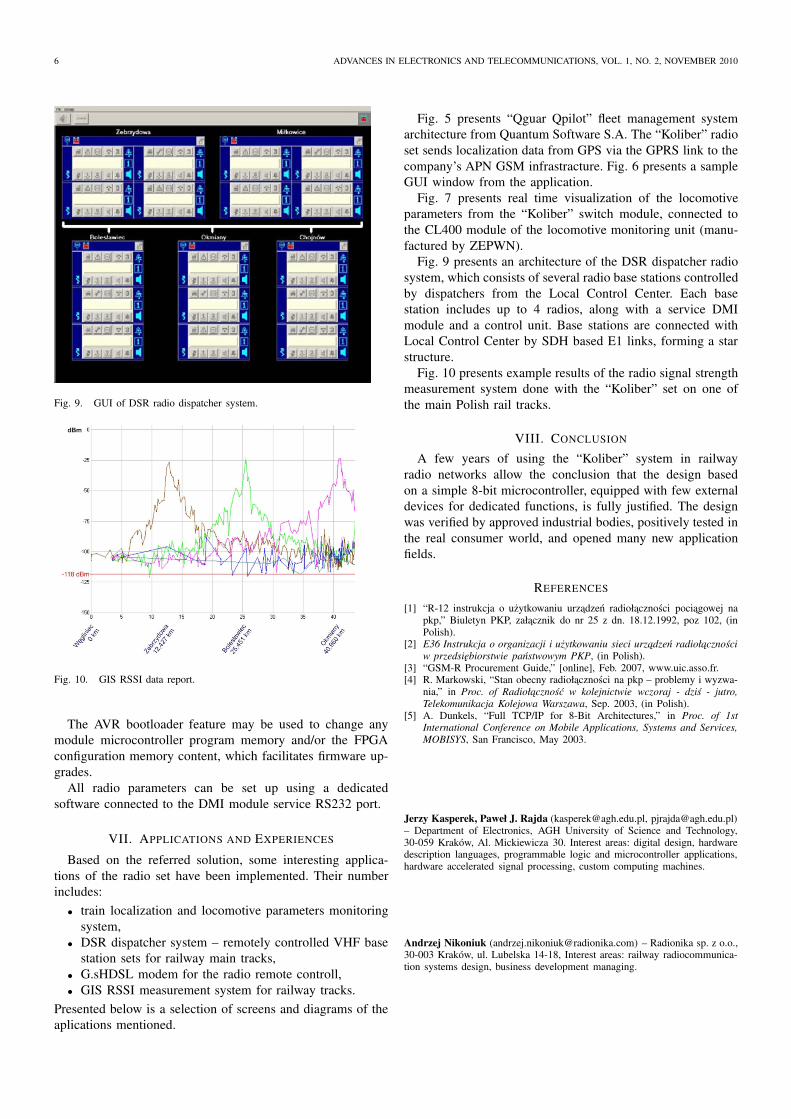
Fig. 10 presents example results of the radio signal strength
measurement system done with the “Koliber” set on one of
the main Polish rail tracks.
VIII. CONCLUSION
A few years of using the “Koliber” system in railway
radio networks allow the conclusion that the design based
on a simple 8-bit microcontroller, equipped with few external
devices for dedicated functions, is fully justified. The design
was verified by approved industrial bodies, positively tested in
the real consumer world, and opened many new application
fields.
REFERENCES
[1] “R-12 instrukcja o uzytkowaniu urzadzen radiołacznosci pociagowej napkp,” Biuletyn PKP, załacznik do nr 25 z dn. 18.12.1992, poz 102, (inPolish).
[2] E36 Instrukcja o organizacji i uzytkowaniu sieci urzadzen radiołacznosci
w przedsiebiorstwie panstwowym PKP, (in Polish).[3] “GSM-R Procurement Guide,” [online], Feb. 2007, www.uic.asso.fr.[4] R. Markowski, “Stan obecny radiołacznosci na pkp – problemy i wyzwa-
nia,” in Proc. of Radiołacznosc w kolejnictwie wczoraj - dzis - jutro,
Telekomunikacja Kolejowa Warszawa, Sep. 2003, (in Polish).[5] A. Dunkels, “Full TCP/IP for 8-Bit Architectures,” in Proc. of 1st
International Conference on Mobile Applications, Systems and Services,
MOBISYS, San Francisco, May 2003.
Jerzy Kasperek, Paweł J. Rajda ([email protected], [email protected])– Department of Electronics, AGH University of Science and Technology,30-059 Kraków, Al. Mickiewicza 30. Interest areas: digital design, hardwaredescription languages, programmable logic and microcontroller applications,hardware accelerated signal processing, custom computing machines.
Andrzej Nikoniuk ([email protected]) – Radionika sp. z o.o.,30-003 Kraków, ul. Lubelska 14-18, Interest areas: railway radiocommunica-tion systems design, business development managing.