MULTIPOINT SS V 50/80 & 100 - Heatrae Sadia · PDF fileThank you for purchasing a Heatrae...
24
MULTIPOINT SS V 50/80 & 100 Fitting Instructions and User Guide
Transcript of MULTIPOINT SS V 50/80 & 100 - Heatrae Sadia · PDF fileThank you for purchasing a Heatrae...
MULTIPOINT SS V 50/80 & 100
Fitting Instructions and User Guide
2
CONTENTSSECTION PAGE
1.0 INTRODUCTION 3
2.0 TECHNICAL SPECIFICATION 4
3.0 INSTALLATION 7
4.0 COMMISSIONING 14
5.0 EXPLANATION TO USER 15
6.0 MAINTENANCE 15
7.0 SPARE PARTS 18
8.0 FAULT FINDING 20
9.0 ACCESSORIES 21
10.0 GUARANTEE 22
11.0 ENVIRONMENTAL INFORMATION 23
12.0 SPARES STOCKISTS 24
The HWA Charter Statement requires that all members adhere to the following: ` To supply fit for purpose products clearly and honestly described. ` To supply products that meet, or exceed appropriate standards and
building and water regulations. ` To provide pre and post sales technical support. ` To provide clear and concise warranty details to customers.
3
1.0 INTRODUCTIONThank you for purchasing a Heatrae Sadia Multipoint SS unvented water heater. The Multipoint SS water heater is manufactured in the UK to the highest standards and has been designed to meet all the latest relevant safety specifications.
1.1 IMPORTANT POINTS
The Multipoint SS must be installed and commissioned by a competent person. Please read and understand these instructions before installing the Multipoint SS. Following installation and commissioning, the operation of the Multipoint SS should be explained to the user and these instructions left with them for future reference.
This appliance can be used by children aged from 8 years and above and persons with reduced physical sensory or mental capabilities or lack of experience and knowledge if they have been given supervision or instruction concerning use of the appliance in a safe way and understand the hazards involved. Children shall not play with the appliance. Cleaning and user maintenance shall not be made by children without supervision.
Children must be supervised to ensure they do not play with the appliance..
The Multipoint SS hot water cylinder is of unvented type. Its installation is subject to Building Regulation G3 (England and Wales), Technical Standard P3 (Scotland) or Building Regulation P5 (Northern Ireland). Installation must be carried out by a competent person.
Electrical installation must be carried out in accordance with the current IEE Wiring Regulations.
Prior to installation the unit should be stored in an upright position in an area free from excessive damp or humidity.
4
1.2 PACK CONTENTS
Before commencing installation please check that the following components have been supplied in the Installation Kit:
• Multipoint SS Unit (x1)• Expansion vessel 3/4” BSP male, precharge pressure 3.5bar (x1)• Expansion vessel wall mounting bracket (x1)• Pressure reducing valve 3.5 bar, 22mm x 22mm compression (x1) • Single check valve 22mm x 22mm compression (x1)• Pressure (expansion) Relief Valve 1/2”BSP x 1/2”BSP female, factory
set at 6 bar (x1)• Tundish, 22mm x 15mm compression (x1) • 3/4” compression nuts (x2)• Copper olive, 22mm (x2)• Element plate tool (x1)• Mounting brackets (x4)• User Instructions• Guarantee Card
2.0 TECHNICAL SPECIFICATIONElectrical Rating 3.0kW @ 240v / 2.8kW @ 230vCapacity 50,80 & 100 litresWeight (100 Litre) 30Kg (empty), 130Kg (full)Weight (80 Litre) 24Kg (empty), 104Kg (full)Weight (50 Litre) 18Kg (empty), 68Kg (full)Operating pressure 0.35 MPa (3.5 bar)Rated pressure 0.6 MPa (6.0 bar)Expansion vessel charge pressure 0.35 MPa (3.5 bar)Expansion relief valve setting 0.6 MPa (6.0 bar)Minimum supply pressure 0.08 MPa (0.8 bar)Maximum supply pressure to PRV 1.6 MPa (16.0 bar)Temperature / Pressure Relief Valve 90°C / 1.0 MPa (10.0 bar)
5
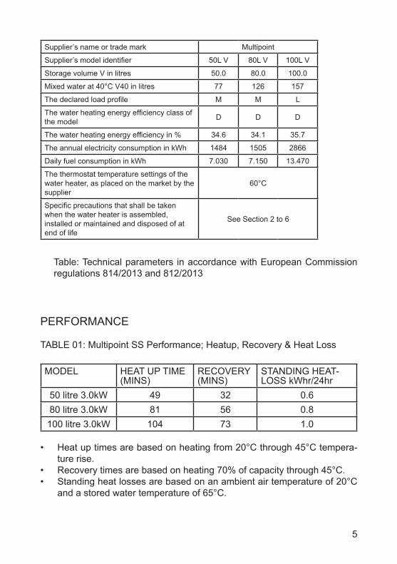
PERFORMANCE
TABLE 01: Multipoint SS Performance; Heatup, Recovery & Heat Loss
MODEL HEAT UP TIME (MINS)
RECOVERY (MINS)
STANDING HEAT-LOSS kWhr/24hr
50 litre 3.0kW 49 32 0.680 litre 3.0kW 81 56 0.8
100 litre 3.0kW 104 73 1.0
• Heat up times are based on heating from 20°C through 45°C tempera-ture rise.
• Recovery times are based on heating 70% of capacity through 45°C.• Standing heat losses are based on an ambient air temperature of 20°C
and a stored water temperature of 65°C.
Supplier’s name or trade mark Multipoint
Supplier’s model identifier 50L V 80L V 100L V
Storage volume V in litres 50.0 80.0 100.0
Mixed water at 40°C V40 in litres 77 126 157
The declared load profile M M L
The water heating energy efficiency class of the model D D D
The water heating energy efficiency in % 34.6 34.1 35.7
The annual electricity consumption in kWh 1484 1505 2866
Daily fuel consumption in kWh 7.030 7.150 13.470
The thermostat temperature settings of the water heater, as placed on the market by the supplier
60°C
Specific precautions that shall be taken when the water heater is assembled, installed or maintained and disposed of at end of life
See Section 2 to 6
Table: Technical parameters in accordance with European Commission regulations 814/2013 and 812/2013
6
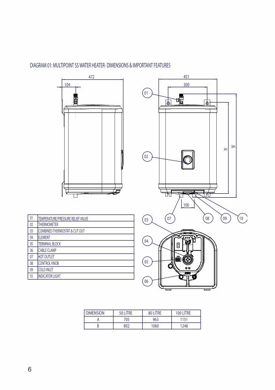
DIAGRAM 01: MULTIPOINT SS WATER HEATER- DIMENSIONS & IMPORTANT FEATURES
01 TEMPERATURE/PRESSURE RELIEF VALVE02 THERMOMETER03 COMBINED THERMOSTAT & CUT OUT04 ELEMENT05 TERMINAL BLOCK06 CABLE CLAMP07 HOT OUTLET08 CONTROL KNOB09 COLD INLET10 INDICATOR LIGHT
DIMENSION 50 LITRE 80 LITRE 100 LITREA 705 963 1151B 802 1060 1248
300
451
100
'B''A'
01
02
08 1007 09
472
104
04
06
05
03
7
3.0 INSTALLATION Warning: this appliance must be earthed. It is suitable for A.C. supply only. Electrical installation must be carried out by a competent electrician and be in accordance with the latest I.E.E. wiring regulations.
Ensure the electrical supply is switched off before making any connections to the Multipoint SS.
The Multipoint SS unvented water heater is factory fitted with a Temperature/Pressure Relief Valve which must not be removed, blocked or restricted in any way.
Expansion MUST be accommodated within the system. The expansion ves-sel & check valve provided in the installation kit must be installed and will fulfill this function.
3.1 LOCATION
1. Using Diagram 01 and the dimensions table as a guide mark the positions of the fixing points. Drill and plug the wall with suitable fixings.
2. Fix the top two fixings first followed by the bottom two fixings.3. The Multipoint SS must be plumb and vertically wall mounted using the
wall brackets fitted to the heater. The water connections must always be at the bottom of the unit.
4. Enough space should be left below the unit for pipe connections and above the unit for access to the Temperature/Pressure Relief Valve (400 mm minimum). Refer to Diagram 01 and the Dimensions Table to deter-mine a suitable position for the heater.
5. Ensure that the wall can support the full weight of the unit and that there are no hidden services (electricity, gas or water) below the surface of the wall.
6. DO NOT install where the unit may freeze.7. DO NOT install in direct sunlight or where the unit is open to the ele-
ments.8. The latest IEE wiring regulations may contain restrictions concerning the
installation of these units in bathrooms.
NOTE: THE MULTIPOINT WATER HEATER IS HEAVY. PRIOR TO FIXTURE ENSURE THE WALL IS STRONG ENOUGH TO TAKE THE WEIGHT OF THE WATER HEATER WHEN FULL.
8
Multipoint SS50, 80, 100
LitreHeater
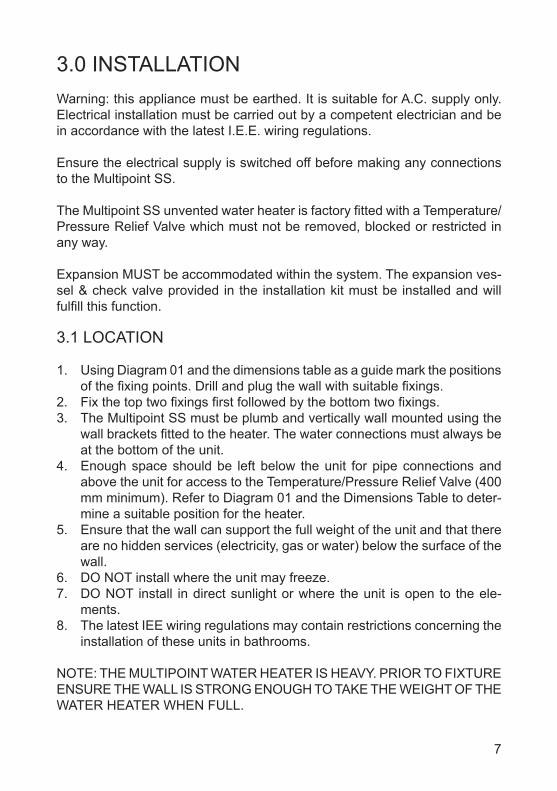
DIAGRAM 02: PLUMBING SCHEMATIC
No other valves should be placed between the expansion valve and the Multipoint SS cylinder. The expansion valve connection must not be used for any other purpose.
3.2 PLUMBING
1. To make installation of the Multipoint SS easier it is supplied with a Non Return Valve, Expansion Vessel and Pressure Relief Valve.
2. Plumb the Multipoint water heater as shown below in Diagram 02. Ensure the Pressure Reducing Valve is installed in the correct orientation by reference to the direction of the flow arrow marked on it.
3. The water connections to the unit are 3/4” BSP male with Ø22 mm compression fittings suitable for Ø22 mm copper pipe.
4. Inlet and outlet are colour coded accordingly for hot and cold. Several hot outlets via conventional taps can be served, however, individual site demands should be considered when choosing capacity and the number of outlets.
5. It is recommended that a WRAS listed isolating valve (not supplied) is fitted on the cold water supply to the heater before the Pressure Reducing Valve.
6. Plumbers Paste must not be used as it can impair the operation of the valves.
9
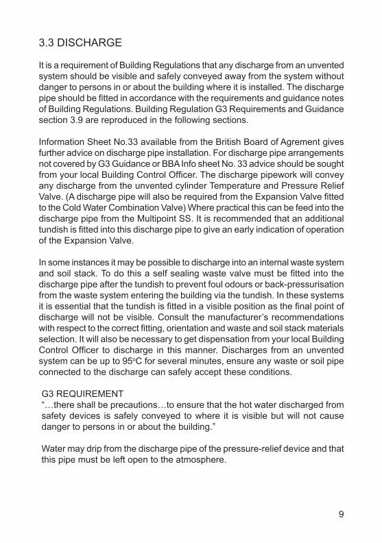
3.3 DISCHARGE
It is a requirement of Building Regulations that any discharge from an unvented system should be visible and safely conveyed away from the system without danger to persons in or about the building where it is installed. The discharge pipe should be fitted in accordance with the requirements and guidance notes of Building Regulations. Building Regulation G3 Requirements and Guidance section 3.9 are reproduced in the following sections.
Information Sheet No.33 available from the British Board of Agrement gives further advice on discharge pipe installation. For discharge pipe arrangements not covered by G3 Guidance or BBA Info sheet No. 33 advice should be sought from your local Building Control Officer. The discharge pipework will convey any discharge from the unvented cylinder Temperature and Pressure Relief Valve. (A discharge pipe will also be required from the Expansion Valve fitted to the Cold Water Combination Valve) Where practical this can be feed into the discharge pipe from the Multipoint SS. It is recommended that an additional tundish is fitted into this discharge pipe to give an early indication of operation of the Expansion Valve.
In some instances it may be possible to discharge into an internal waste system and soil stack. To do this a self sealing waste valve must be fitted into the discharge pipe after the tundish to prevent foul odours or back-pressurisation from the waste system entering the building via the tundish. In these systems it is essential that the tundish is fitted in a visible position as the final point of discharge will not be visible. Consult the manufacturer’s recommendations with respect to the correct fitting, orientation and waste and soil stack materials selection. It will also be necessary to get dispensation from your local Building Control Officer to discharge in this manner. Discharges from an unvented system can be up to 95oC for several minutes, ensure any waste or soil pipe connected to the discharge can safely accept these conditions.
G3 REQUIREMENT“…there shall be precautions…to ensure that the hot water discharged from safety devices is safely conveyed to where it is visible but will not cause danger to persons in or about the building.”
Water may drip from the discharge pipe of the pressure-relief device and that this pipe must be left open to the atmosphere.
10
The expansion relief valve is to be operated regularly to remove lime deposits and to verify that it is not blocked.
The discharge pipe connected to the pressure relief device is to be installed in a continuously downward direction and in a frost free environment
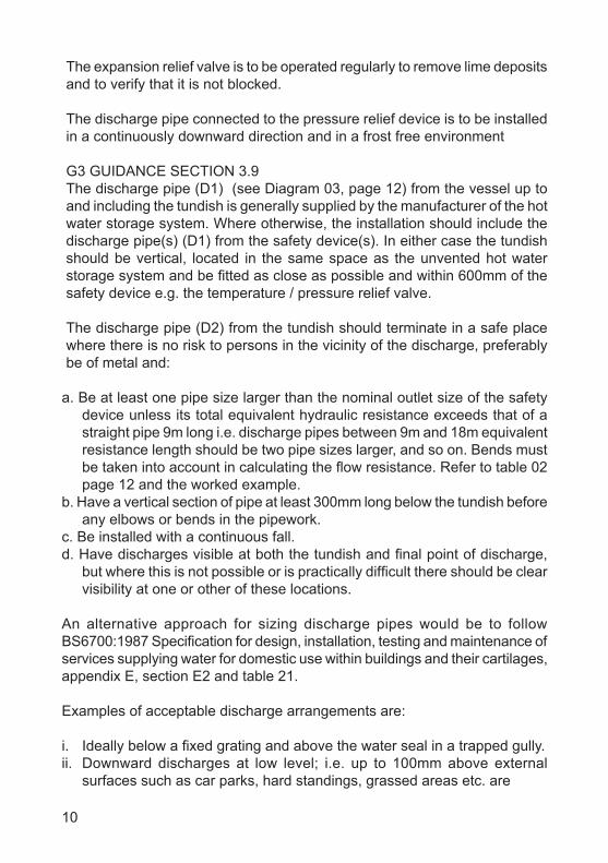
G3 GUIDANCE SECTION 3.9The discharge pipe (D1) (see Diagram 03, page 12) from the vessel up to and including the tundish is generally supplied by the manufacturer of the hot water storage system. Where otherwise, the installation should include the discharge pipe(s) (D1) from the safety device(s). In either case the tundish should be vertical, located in the same space as the unvented hot water storage system and be fitted as close as possible and within 600mm of the safety device e.g. the temperature / pressure relief valve.
The discharge pipe (D2) from the tundish should terminate in a safe place where there is no risk to persons in the vicinity of the discharge, preferably be of metal and:
a. Be at least one pipe size larger than the nominal outlet size of the safety device unless its total equivalent hydraulic resistance exceeds that of a straight pipe 9m long i.e. discharge pipes between 9m and 18m equivalent resistance length should be two pipe sizes larger, and so on. Bends must be taken into account in calculating the flow resistance. Refer to table 02 page 12 and the worked example.
b. Have a vertical section of pipe at least 300mm long below the tundish before any elbows or bends in the pipework.
c. Be installed with a continuous fall.d. Have discharges visible at both the tundish and final point of discharge,
but where this is not possible or is practically difficult there should be clear visibility at one or other of these locations.
An alternative approach for sizing discharge pipes would be to follow BS6700:1987 Specification for design, installation, testing and maintenance of services supplying water for domestic use within buildings and their cartilages, appendix E, section E2 and table 21.
Examples of acceptable discharge arrangements are:
i. Ideally below a fixed grating and above the water seal in a trapped gully.ii. Downward discharges at low level; i.e. up to 100mm above external
surfaces such as car parks, hard standings, grassed areas etc. are
11
acceptable providing that where children may play or otherwise come into contact with discharges a wire cage or similar guard is positioned to prevent contact, whilst maintaining visibility.
iii. Discharges at high level; e.g. into a metal hopper and metal down pipe with the end of the discharge pipe clearly visible (tundish visible or not) or onto a roof capable of withstanding high temperature discharges of water and 3m from any plastics guttering system that would collect such discharges (tundish visible).
iv. Where a single pipe serves a number of discharges, such as in blocks of flats, the number served should be limited to not more than 6 systems so that any installation discharging can be traced reasonably easily. The single common discharge pipe should be at least one pipe size larger than the largest individual discharge pipe (D2) to be connected. If unvented hot water storage systems are installed where discharges from safety devices may not be apparent i.e. in dwellings occupied by blind, infirm or disabled people, consideration should be given to the installation of an electronically operated device to warn when discharge takes place.
Note: The discharge will consist of scalding water and steam. Asphalt, roofing felt and non-metallic rainwater goods may be damaged by such discharges.
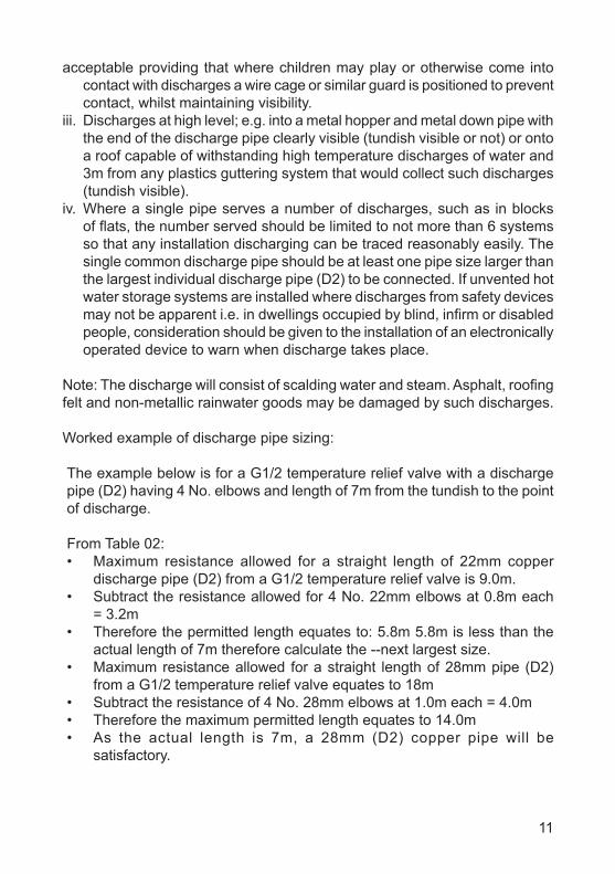
Worked example of discharge pipe sizing:
The example below is for a G1/2 temperature relief valve with a discharge pipe (D2) having 4 No. elbows and length of 7m from the tundish to the point of discharge.
From Table 02:• Maximum resistance allowed for a straight length of 22mm copper
discharge pipe (D2) from a G1/2 temperature relief valve is 9.0m.• Subtract the resistance allowed for 4 No. 22mm elbows at 0.8m each
= 3.2m• Therefore the permitted length equates to: 5.8m 5.8m is less than the
actual length of 7m therefore calculate the --next largest size.• Maximum resistance allowed for a straight length of 28mm pipe (D2)
from a G1/2 temperature relief valve equates to 18m• Subtract the resistance of 4 No. 28mm elbows at 1.0m each = 4.0m• Therefore the maximum permitted length equates to 14.0m• As the actual length is 7m, a 28mm (D2) copper pipe will be
satisfactory.
12
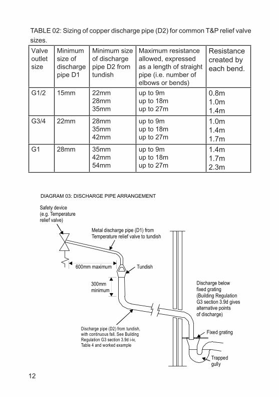
Fixed grating
Discharge belowfixed grating(Building RegulationG3 section 3.9d givesalternative pointsof discharge)
Trappedgully
Discharge pipe (D2) from tundish,with continuous fall. See BuildingRegulation G3 section 3.9d i-iv,Table 4 and worked example
300mmminimum
600mm maximum
Metal discharge pipe (D1) fromTemperature relief valve to tundish
Tundish
Safety device(e.g. Temperaturerelief valve)
DIAGRAM 03: DISCHARGE PIPE ARRANGEMENT
TABLE 02: Sizing of copper discharge pipe (D2) for common T&P relief valve sizes.Valve outlet size
Minimum size of discharge pipe D1
Minimum size of discharge pipe D2 from tundish
Maximum resistance allowed, expressed as a length of straight pipe (i.e. number of elbows or bends)
Resistance created by each bend.
G1/2 15mm 22mm28mm35mm
up to 9mup to 18mup to 27m
0.8m1.0m1.4m
G3/4 22mm 28mm35mm42mm
up to 9mup to 18mup to 27m
1.0m1.4m1.7m
G1 28mm 35mm42mm54mm
up to 9mup to 18mup to 27m
1.4m1.7m2.3m
13
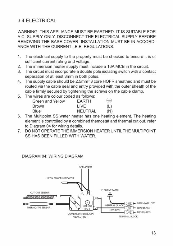
3.4 ELECTRICAL
WARNING: THIS APPLIANCE MUST BE EARTHED. IT IS SUITABLE FOR A.C. SUPPLY ONLY. DISCONNECT THE ELECTRICAL SUPPLY BEFORE REMOVING THE BASE COVER. INSTALLATION MUST BE IN ACCORD-ANCE WITH THE CURRENT I.E.E. REGULATIONS.
1. The electrical supply to the property must be checked to ensure it is of sufficient current rating and voltage.
2. The immersion heater supply must include a 16A MCB in the circuit.3. The circuit must incorporate a double pole isolating switch with a contact
separation of at least 3mm in both poles.4. The supply cable should be 2.5mm² 3 core HOFR sheathed and must be
routed via the cable seal and entry provided with the outer sheath of the cable firmly secured by tightening the screws on the cable clamp.
5. The wires are colour coded as follows: Green and Yellow EARTH Brown LIVE (L) Blue NEUTRAL (N)6. The Multipoint SS water heater has one heating element. The heating
element is controlled by a combined themostat and thermal cut out, refer to Diagram 04 for wiring details.
7. DO NOT OPERATE THE IMMERSION HEATER UNTIL THE MULTIPOINT SS HAS BEEN FILLED WITH WATER.
CUT-OUT SENSOR
THERMOSTAT SENSOR
COMBINED THERMOSTAT AND CUT OUT
TO ELEMENT
GREEN&YELLOW
BROWN/RED
BLUE/BLACK
ELEMENT EARTH
LIVE (RED)
NEUTRAL (BLACK)
TERMINAL BLOCK
CUT OUT RESET A
B
12
DIAGRAM 04: WIRING DIAGRAM
NEON POWER INDICATOR
14
4.0 COMMISSIONING4.1 PLUMBING
WARNING: Water that is left standing in a stainless steel water cylinder for long periods without draw-off will become de-oxygenated and potentially corrode the vessel material. If the installation is to be left unused following installation and commissioning, the water cylinder must be drained or regularly flushed (once a week) through with fresh mains water.
1. Check that all installation and discharge pipe requirements have been met.
2. Check that all water connections are tight.3. Open a hot water tap, turn on mains water supply to the Multipoint SS.4. Allow Multipoint SS to fill and leave hot tap running for a short while to
purge any air and flush out the pipework. Close the hot tap and check the system for leaks.
5. Manually test the operation of the Temperature/Pressure Relief Valve and the Pressure (expansion) Relief Valve. Ensure water flows freely from the valves and through the discharge pipes.
4.2 ELECTRICAL
PRELIMINARY CHECKSEnsure all power supplies are switched off.Check all electrical connections are tight.Check all earth bonding links are connected, tight and un-damaged.Check earth continuity, short circuits, polarity and resistance to earth.
1. Do not switch on the electrical supply until the Multipoint SS has been filled with water and checked for leaks.
2. Check that all electrical requirements have been met.3. Check that all electrical connections are tight.4. Switch on the electrical supply. The indicator light will illuminate during
heating. When the set temperature is reached the indicator light will go out.
5. The set temperature can be adjusted by rotating the control knob. This can be set to give temperatures in the range 10°C to 70°C. In hard water areas it is advised that the maximum temperature is restricted to prevent build up of scale.
15
5.0 EXPLANATION TO USER 1. The Multipoint SS unvented heater stores water at the temperature set on
the adjustable control knob. This can be set to give temperatures in the range 10°C to 70°C. In hard water areas it is advised that the maximum temperature is restricted to prevent build up of scale. To avoid risk of freezing when the heater is not in use for long periods during the winter months, do not switch off the electrical supply and set the thermostat to its minimum position. N.B. This will not protect other system pipework.
2. The indicator lights will be illuminated when the unit is heating.3. To ensure the heater continues to operate at its optimum performance
it should be periodically maintained in accordance with the instructions given under the section headed MAINTENANCE.
IMPORTANT NOTES TO USER• DO NOT BLOCK OR RESTRICT THE DISCHARGE FROM ANY SAFETY
VALVE FITTED.• DO NOT TAMPER WITH ANY SAFETY VALVE FITTED.• IF WATER DISCHARGES FROM ANY SAFETY VALVE FITTED SWITCH
OFF THE ELECTRICAL SUPPLY TO THE UNIT IMMEDIATELY. CONTACT THE HEATRAE SADIA SERVICE TEAM (TEL: 0844 8711530) OR AN APPROVED INSTALLER. DO NOT TURN THE ELECTRICAL SUPPLY ON AGAIN UNTIL THE UNIT HAS BEEN CHECKED AND APPROVED BY A QUALIFIED INSTALLER.
6.0 MAINTENANCEWARNING: DISCONNECT FROM ALL ELECTRICAL SUPPLIES BEFORE BEGINNING ANY WORK ON THE MULTIPOINT SS. FLUID CONTAINED IN THE CYLINDER MAY BE VERY HOT!
To ensure the continued safe and efficient operation of the Multipoint SS it should be regularly maintained.
Maintenance should be carried out by a competent person and any replacement parts used should be authorised Heatrae Sadia Multipoint SS spare parts.
It is recommended that maintenance is carried out annually and should include the checks detailed in the sections on page 16 & 17.
16
6.1 DESCALING
Little maintenance is required, however in hard water areas the unit will require periodic descaling to ensure efficient operation. To descale the unit:1. Switch off and disconnect the electrical supply. Turn off the water
supply to the unit.2. Open a hot tap to relieve any system pressure. Empty unit by opening
the drain cock in the inlet pipework.3. Remove the terminal cover by removing the two supporting screws
holding it in place.4. Disconnect the electrical terminals to the element. Withdraw the
thermostat and thermal cut-out capillary tubes from the pockets on the element plate.
5. Remove the element plate assembly by unscrewing the element backnut using the element tool provided (NOTE: a quantity of water may still be present in the container, it is recommended that a container be placed under the unit to collect any spillage).
6. Remove any loose scale from the container. Carefully clean off any scale from the element and thermostat pocket. DO NOT clean scale from interior container walls.
7. Re-assemble the element plate assembly fitting a new sealing gasket. Rewire the unit with reference to Diagram 04 (wiring diagram).
8. Re-commission the unit following the INSTALLATION and COMMISSIONING instructions.
6.2 SAFETY VALVES
The Temperature/Pressure Relief Valve and the Pressure (Expansion) Relief Valve should be regularly checked. To check the valves:
1. Manually operate the valve by twisting the cap. Ensure water flows freely from the valves and through the discharge pipes (NOTE: the water discharged may be very hot). Ensure the valves reseat correctly when released.
2. Clean the strainer incorporated in the Pressure Reducing Valve. To inspect and clean the strainer turn off the mains water supply to the heater and open a hot tap to relieve the system pressure. Unscrew the black cap from the Pressure Reducing Valve and remove. The strainer will be removed with the cap. Wash any particulate matter from the strainer under COLD CLEAR WATER ONLY. Replace the cap assembly ensuring the sealing ring is correctly fitted. Do not use any other type of sealant. Close hot tap, open mains stop cock and check for leaks.
17
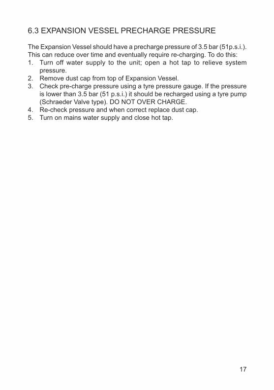
6.3 EXPANSION VESSEL PRECHARGE PRESSURE
The Expansion Vessel should have a precharge pressure of 3.5 bar (51p.s.i.). This can reduce over time and eventually require re-charging. To do this:1. Turn off water supply to the unit; open a hot tap to relieve system
pressure.2. Remove dust cap from top of Expansion Vessel.3. Check pre-charge pressure using a tyre pressure gauge. If the pressure
is lower than 3.5 bar (51 p.s.i.) it should be recharged using a tyre pump (Schraeder Valve type). DO NOT OVER CHARGE.
4. Re-check pressure and when correct replace dust cap.5. Turn on mains water supply and close hot tap.
18
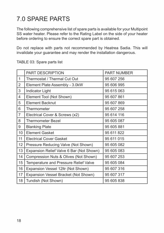
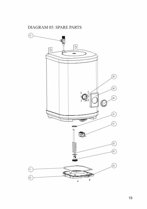
7.0 SPARE PARTSThe following comprehensive list of spare parts is available for your Multipoint SS water heater. Please refer to the Rating Label on the side of your heater before ordering to ensure the correct spare part is obtained.
Do not replace with parts not recommended by Heatrea Sadia. This will invalidate your guarantee and may render the installation dangerous.
TABLE 03: Spare parts list
PART DESCRIPTION PART NUMBER1 Thermostat / Thermal Cut Out 95 607 2562 Element Plate Assembly - 3.0kW 95 606 9953 Indicator Light 95 615 0634 Element Tool (Not Shown) 95 607 8615 Element Backnut 95 607 8696 Thermometer 95 607 2587 Electrical Cover & Screws (x2) 95 614 1168 Thermometer Bezel 95 605 0879 Blanking Plate 95 605 88110 Element Gasket 95 611 82211 Electrical Cover Gasket 95 611 01512 Pressure Reducing Valve (Not Shown) 95 605 08213 Expansion Relief Valve 6 Bar (Not Shown) 95 605 08314 Compression Nuts & Olives (Not Shown) 95 607 25315 Temperature and Pressure Relief Valve 95 605 08416 Expansion Vessel 12ltr (Not Shown) 95 607 31617 Expansion Vessel Bracket (Not Shown) 95 607 31718 Tundish (Not Shown) 95 605 838
19
15
11
07
05
02
01
10
06
08
09
03
DIAGRAM 05: SPARE PARTS
20
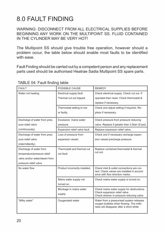
8.0 FAULT FINDINGWARNING: DISCONNECT FROM ALL ELECTRICAL SUPPLIES BEFORE BEGINNING ANY WORK ON THE MULTIPOINT SS. FLUID CONTAINED IN THE CYLINDER MAY BE VERY HOT!
The Multipoint SS should give trouble free operation, however should a problem occur, the table below should enable most faults to be identified with ease.
Fault Finding should be carried out by a competent person and any replacement parts used should be authorised Heatrae Sadia Multipoint SS spare parts.
TABLE 04: Fault finding tableFAULT POSSIBLE CAUSE REMEDY
Water not heating Electrical supply fault.
Thermal cut out tripped.
Check electrical supply. Check cut out. If
operated then reset. Check thermostat &
replace if necessary.
Thermostat setting to low
or faulty.
Check and adjust setting if required. Re-
place if necessary.
Discharge of water from pres-
sure relief valve
(continuously).
Excessive mains water
pressure.
Check pressure from pressure reducing
valve. Replace if greater than 3.5bar (51psi)
Expansion relief valve fault. Replace expansion relief valve.
Discharge of water from pres-
sure relief valve
(intermittently).
Loss of pressure from
expansion vessel.
Check and if necessary recharge expan-
sion vessel precharge pressure.
Discharge of water from
temperature/pressure relief
valve and/or water/steam from
pressure relief valve
Thermostat and thermal cut
out fault.
Replace combined thermostat & thermal cut out.
No water flow Product incorrectly installed. Check inlet & outlet connections are cor-rect. Check valves are installed in accord-ance with flow direction marks.
Mains water supply not
turned on.
Check mains water supply is turned on.
Blockage in mains water
supply.
Check mains water supply for obstructions. Check expansion relief valve.Check strainer in pressure reducing valve.
“Milky water” Oxygenated water Water from a pressurised system releases oxygen bubbles when flowing. The milki-ness will disappear after a short while.

21
9.0 ACCESSORIESThe heater can be used to supply several hot water outlets via conventional taps. Individual site demands should be considered when choosing capacity and the number of outlets to be served.A Thermostatic Blending Valve can be used in conjunction with the Multipoint Water Heater. Heatrae Sadia supply both TMV2 approved (Pack U3, code number 95 970 354) and TMV3 approved (Pack U7 95 970 360) Thermostatic Blending Valves.
22
10.0 GUARANTEEThis Multipoint SS is guaranteed against faulty materials and manufacture provided that:
• The Multipoint SS has been installed in accordance with the installation and service instructions and all relevant Codes of Practice and Regula-tions in force at the time of installation, and that all necessary controls and safety valves have been fitted correctly.
• Any valves and controls fitted are of Heatrae Sadia recommended type and specification.
• The Multipoint SS has not been modified or tampered with in any way, and has been regularly maintained as detailed in these instructions.
• The domestic hot water cylinder has only been used for the storage of wholesome water as defined by the Water Supply (Water Fittings) Regu-lations 1999.
• Within 60 days of installation the user completes and returns the guarantee registration card supplied with the unit in order to register the product.
• It has only been used for the storage of potable water. (Max 250mg/l chloride)
• Following commissioning the unit is put into service within a period of 7 days. If this is not the case it must either be drained or regularly flushed as required in the section “Commissioning -Warning”
The unit is not guaranteed against damage by frost and the immersion heater is not guaranteed against excessive scale build-up.
Periodic loss of charge pressure from the expansion vessels is normal (indi-cated by an intermittent discharge of water from the pressure relief valves) and is not covered under the product guarantee.
The following guarantee periods apply from the date of purchase:
Stainless steel hot water cylinder 15 yearsAll other components 2 years
This guarantee does not affect your statutory rights.

23
11.0 ENVIRONMENTAL INFORMATIONThis product is manufactured from many recyclable materials. At the end of its useful life it should be disposed of at a Local Authority Recycling Centre in order to realise the full environmental benefits.
Insulation of the domestic hot water cylinder is by means of an approved CFC/HCFC free polyurethane foam with an ozone depletion factor of zero and a Global Warming Potential (GWP) of 3.1.
The Multipoint SS does not contain any substances harmful to health; it does not contain any asbestos.

36006070_issue_04
Heatrae Sadia Heating Hurricane Way Norwich NR6 6EAwww.heatraesadia.com
Service: 0344 8711535Service Fax: 0344 8711528 Email: heatraesadia.service@
heateam.co.uk
12.0 SPARES STOCKISTSFor the fast and efficient supply of spares please contact the stockists listed below:
Advanced Water Company Ltd.Unit D5 Enterprise wayVale park, EveshamWorcs, WR11 1GSTel: 01386 760066Fax: 01386 760077
Electric Water Heating Co. 2 Horsecroft Place, PinnaclesHarlow, Essex, CM19 5BTTel: 0845 0553811E-Mail: [email protected]
SPDUnits 9 & 10 Hexagon Business CentreSpringfield Road, HayesMiddlesex, UB40 0TYTel: 020 8606 3567
Parts CenterTel: 0845 2709800www.partscenter.co.uk
Newey & EyreSpecialist Products DivisionPlease contact your local branch
UK Spares Ltd.Tower Lane, WarmleyBristol, BS30 8XTTel: 0117 961 6670
William Wilson Ltd.Unit 3A, 780 South StreetWhiteinch, Glasgow, G14 OSYTel: 0141 434 1530
© 2015