
MULTIPOINT EARTH LEAKAGE RELAY CBS-8 … · case of an earth fault event. ... instantaneous RMS...
36
MULTIPOINT EARTH LEAKAGE RELAY CBS-8 SERIES USER’S MANUAL ( M 981 581 / 01D) (c) CIRCUTOR S.A.
Transcript of MULTIPOINT EARTH LEAKAGE RELAY CBS-8 … · case of an earth fault event. ... instantaneous RMS...

MULTIPOINT EARTH LEAKAGERELAY
CBS-8 SERIES
USER’S MANUAL( M 981 581 / 01D)
(c) CIRCUTOR S.A.

--------- Central of residual current relays CBS-8 -------- Page No. 1
CBS-8 USER’S MANUAL CONTENT page1.- CHECKING THE CONTENTS OF YOUR PACKAGE.................................................. 22.- GENERAL FEATURES................................................................................................ 33.- INSTALLATION AND STARTUP ................................................................................. 5
3.1.- Installing the CBS-8........................................................................................ 53.2.- CBS-8 connection terminal (according to specification in lables) ................... 73.3.- CBS-8 connection drawings............................................................................ 8
3.3.1.- To function as an earth leakage current meter ......................................... 83.3.2.- To function as a residual current protective device................................... 9
4.- OPERATION MODE...................................................................................................104.1.- Normal mode.................................................................................................114.2.- Test Mode .....................................................................................................144.3.- Reset mode ...................................................................................................164.4.- Setup mode ...................................................................................................17
5.- SETTING UP THE CBS-8 ..........................................................................................185.1.- Channel setting..............................................................................................18
5.1.1.- Common parameter setting .....................................................................195.1.2.- Channel setting .......................................................................................20
5.2.- Communication setting ..................................................................................255.3.- On-board clock setting...................................................................................26
6.- TECHNICAL SPECIFICATIONS.................................................................................277.- SAFETY CONSIDERATIONS.....................................................................................298.- MAINTENANCE..........................................................................................................299.- TECHNICAL SERVICE...............................................................................................2910.- CBS-8 COMMUNICATIONS.......................................................................................30
10.1.- To take into account!: ..................................................................................3010.2.- Connection of a RS-485 network to a PC (RS-232).....................................3110.3.- MODBUS © Protocol ...................................................................................32
10.3.1.- Readout registers ..................................................................................3310.3.2.- Working registers ..................................................................................3510.3.3.- Self-reclosing feature ............................................................................35

--------- Central of residual current relays CBS-8 -------- Page No. 2
1.- CHECKING THE CONTENTS OF YOUR PACKAGEThis manual is aimed to familiarize the user with the operation of the central of
residual current relays model CBS-8, in order to get the best from its features. Afterreceiving the analyzer, please check the following points:
a) The delivered material meets your order specifications.b) After unpacking, check that the instrument has not been damaged in transit.c) The standard set includes the pertinent user’s manual.d) CD with software “Easycomm CBS-8”.
The manual you hold in your hands contains information andwarnings about the CBS-8 that the user should respect in order toguarantee a proper operation of all the instrument functions andkeep its safety conditions.
Before powering the instrument for the first time, verify following points:(a) Power supply: see specifications in the side stuck lable.
���� Standard : 230 V a.c. - Single-phase, 50 ... 60 Hz���� On demand: other supply voltages
(b) Maximum admissible current: according to the associated transformer (WGor WGP).

--------- Central of residual current relays CBS-8 -------- Page No. 3
2.- GENERAL FEATURESThe CBS-8 central of residual current relays is a DIN rail mounting apparatus
that offers several operation possibilities which are selectable within its SETUPmode. Before power supplying the instrument, read the INSTALLATION ANDSTARTUP and SETUP sections and choose the most suitable operation mode inorder to get your desired results.
EdEdEdEd
RdRdRdRd
S1S1S1S1 S1S1S1S1S2S2S2S2 S2S2S2S2S2S2S2S2 S2S2S2S2S1S1S1S1 S1S1S1S1
The CBS-8 is an instrument that measures, calculates and displays the earthleakage current, also with the ability of taking decisions about the action to beexecuted. For this purpose, it has 8 input channels, 8 relay-type outputs (1 per eachchannel), one configurable pre-alarm output, and one test output.
--------- Central of residual current relays CBS-8 -------- Page No. 4
The measurement of the earth leakage current is accomplished by thecalculation of the true RMS value over 1-cycle sliding window. If this measured valueexceeds the allowable threshold (user-programmable) during, an also user-programmable, time period, then the pertinent relay output would be activated.
Depending on the CBS-8 programming, the user will be able to set a series ofdelay times to define the schedule of self-reclosing actions executed by the CBS-8 incase of an earth fault event. This option can only be activated by using the software“Easycomm CBS-8” included in the product package.
The CBS-8 has one LCD display that permits the user to view theinstantaneous RMS value of the earth leakage, as well as the relay status, at each ofthe 8 channels of the CBS-8.
---------------------------------------------------------------------------------------------
OTHER FEATURES- Low-size instrument for DIN rail mounting.- True RMS measuring mode.- Measurement of earth leakage currents at 8 single channels.- Relay for pre-alarm purposes.- Events log- RS-485 communication to PC- Possibility to program automatic reconnection (via RS-485)

--------- Central of residual current relays CBS-8 -------- Page No. 5
3.- INSTALLATION AND STARTUP
The manual you hold in your hands contains information andwarnings that the user should respect in order to guarantee a properoperation of all the instrument functions and keep its safety conditions.The instrument must not be powered and used until its definitiveassembly inside the switchgear cabinet.
If the instrument is not used as manufacturer’s specifications,the protection of the instrument can be damaged.
When any protection failure is suspected to exist (for example, it presentsexternal visible damages), the instrument must be immediately powered off. In thiscase contact a qualified service representative.
3.1.- Installing the CBS-8Before powering the apparatus up, please check following points:a.- Power supply: see the lable stuck in the side of the instrument.
- Standard supply: Single-phase 230 V∼ (a.c.)���� On demand: other supply voltages
- Frequency : 50 - 60 Hz- Supply tolerance : -20 % / +15 %- Connection terminal : Terminals 1-28 (Power supply)- Burden : 4 VA
--------- Central of residual current relays CBS-8 -------- Page No. 6
b.- Maximum admissible current: according to the associated transformer WGxx 30 mA - 3 A WGPxx 300 mA - 30 A
c.- Operation conditions:- Operation temperature : -10 ºC to +50 ºC- Relative humidity : 5 a 95 % HR (non condensing)- Altitude : below 2000 m
e.- Safety- Designed to meet protection class III- 300 V a.c. as per (EN 61010).- Protection against electric shock by class II double-insulation
Mounting : The Instrument is to be onto DIN 46277 (EN 50022) rail. All connections keep
inside the cabinet.
Note that with the instrument powered on, the terminals could be dangerous totouching and cover opening actions or elements removal may allow accessingdangerous parts. Therefore, the instrument must not be used until this is completelyinstalled.
The instrument must be connected to a power supply circuit protected with gltype (IEC 269) or M type fuses rated between 0.5 and 2 A. This circuit should beprovided with a circuit breaker or any equivalent element to connect (ON) ordisconnect (OFF) the instrument from the power supply network.

--------- Central of residual current relays CBS-8 -------- Page No. 7
3.2.- CBS-8 connection terminal (according to specification in lables)No. Description Concept
1 - 28 Power SupplyA1 - A2
Power supply 230 V a.c.
27 – 26 Test 1 - Test 2 Test output25 COM Relay output common24 RL1 Channel 1 relay output23 RL2 Channel 2 relay output22 RL3 Channel 3 relay output21 RL4 Channel 4 relay output20 RL5 Channel 5 relay output19 RL6 Channel 6 relay output18 RL7 Channel 7 relay output17 RL8 Channel 8 relay output
16 - 15 ALARM Pre-alarm relay output
141312
GND( -- )(+ )
COM CBS-8: RS-485 connection to PC. 14 GND ----------> 5 RS-485/RS-232 13 -- ----------> 2 (--) converter 12 + ----------> 1 (+)
11 T8–S1 S1 of Channel 8 C.T.10 T7–S1 S1 of Channel 7 C.T.9 common–S2 S2 of Channels 5,6, 7 & 8 C.T.’s8 T6–S1 S1 of Channel 6 C.T.7 T5–S1 S1 of Channel 5 C.T.6 T4–S1 S1 of Channel 4 C.T.5 T3–S1 S1 of Channel 3 C.T.4 common–S2 S2 of Channels 4,3, 2 & 1 C.T.’s3 T2–S1 S1 of Channel 2 C.T.2 T1–S1 S1 of Channel 1 C.T.
NOTE: Current inputs are suitable only for WG or WGP series transformers.

--------- Central of residual current relays CBS-8 -------- Page No. 8
3.3.- CBS-8 connection drawings.3.3.1.- To function as an earth leakage current meter
Ed
Rd
T6 T7T2
T1
T3
T4 T5 T8
1S1 1S2 1S2 1S1 1S1 1S2 1S2 1S1
1S1 1S21S2 1S1 1S1 1S2 1S2 1S1
2S22S1
1S21S1
WGWGP

--------- Central of residual current relays CBS-8 -------- Page No. 9
3.3.2.- To function as a residual current protective device
CBS-8 L1 L3L2 N
WG 1WG 2
Use 1Use 2
2S12S2
1S11S2
2S12S2
1S11S2
BOBIN A-2
Coil 2 Coil 1
EdEdEdEd
RdRdRdRd
--------- Central of residual current relays CBS-8 -------- Page No. 10
4.- OPERATION MODEThe device is suitable for either 50 Hz and 60 Hz power systems, so that the
user must previously set it to the rated frequency of the working network (SeeSection 5.1.1.-).
This instrument can be either used to function as an earth leakage currentmeter or like a complete residual current protective system. The choice will dependon whether the relay outputs of the different channels are connected (residualcurrent protection) or not (earth leakage current meter).
The CBS-8 has diverse operation modes:- Normal mode: The CBS-8 functions as an earth leakage current meter.
In case that the relay outputs are connected, then it will function as aresidual current protection system.
- Test mode: Execution of an analysis of the transformer CBS-8connections, together with a test of the indicating leds.
- Reset mode: allows the reconnection of the channels that have beenpreviously tripped off.
- Setup mode: To accomplish with the CBS-8 programming actions.
When the CBS-8 is powered on, the normal mode will bealways the active operation mode.
The CBS-8 incorporates 4 keys and 5 indicating leds whose function will varyaccording to the operation mode.
The CBS-8 is equipped with an on-board non-volatile rotary memory to savelast 100 events into. Every log will contain information about:
- Date- Tripped channel- Tripping residual current

--------- Central of residual current relays CBS-8 -------- Page No. 11
4.1.- Normal modeThe instrument has a 2-line LCD:
Ed
Rd
When the CBS-8 is powered on, you can view in display some informationabout the instrument itself:
CbS8
xxxx � Software version
, and following you will view:
FrEC
xx � Network frequency (user-programmed)
After some seconds, the instrument is ready for its regular operation andshows one of the available screens depending on the user-defined programming.
NOTE: If the message “max” would be shown in display during the normaloperation, this means that the measured value of the earth leakage current is higherthan user-programmed value of the tripping threshold.

--------- Central of residual current relays CBS-8 -------- Page No. 12
� Push-buttons:The 4 built-in push-buttons permit the user to execute following actions when
working in this operation mode:- RESET Push-button: By pressing this push-button during 3 seconds, the
CBS-8 will enter the reset menu that allows to unlatch one by one all activatedrelays. Additionally all counters of time and self-reclosing actions will be resetto zero.
- TEST Push-button: Access to the Test mode. By pressing this push-buttonduring 3 seconds, the CBS-8 will perform an auto-test of the selected channeland will check the output status, the indicating leds, the electronics, and theconnections between the transformers and the CBS-8.
- MODE Push-button: By pressing this push-button, the CBS-8 willalternatively change the visualization mode in the LCD. Following enumeratedmessages will be shown in screen during few seconds to indicate thevisualization mode selected by the user:
� UIS.1: The value of the residual current in every channel is alternativelydisplayed in screen, also indicating the status of the associated relay(activated or not).
� UIS.2: Display of the value of the residual current in the active channel.� UIS.3: Indication of every channel status. If the output is latched or
tripped, the screen of the indication of the relay status is alternated withother screen that shows the tripping setpoint programmed for this channeltogether with the value of the detected current which has caused thechannel trip.
� UIS.4: Data about the last earth leakage fault is shown in display. Thetime and date of the leakage occurrence are alternately shown in one line,and, equally, the number of the channel the leakage has been detected inand the value of the residual current are alternately shown in the otherline.
� UIS.5: in only one screen the user can have an overview of which are thechannels that have been tripped off: “0” -> channel ON and “1” -> OFF ortripped.

--------- Central of residual current relays CBS-8 -------- Page No. 13
- SELECT Push-button: The function of this push-button will vary accordingto the user-selected visualization mode:
� UIS.2 or UIS.3 Mode: the CBS-8 switches the displayed channel� UIS.4 Mode: to advance within the recorded logs
- MODE + SELECT Push-button: If these two push-buttons aresimultaneously pressed, then two different actions can be performeddepending on the possition of the “Prog” switch:
- Down: enters the setup mode allowing the modification ofany configuration parameter.
- Up (sealable position): enters the setup mode allowing onlyto check or visualize the configuration of the equipment. Itisnot allowed to make any change in the configuration.
- RESET + SELECT Push-button: To set the time of the CBS-8 on-boardclock.
� LedsThe 5 built-in leds in the CBS-8 indicate following parameters:
- Cpu Led: Lights on when the CBS-8 is running- Comm Led: Blinks when any communication is established via the serial
RS-485 communication channel.- Rd Led: Lights on when automatic self-reclosing actions are enabled.
- Led: Lights on when any channel is tripped. It will flash in case that inany channel the prealarm condition is accomplished, having no otherchannel tripped off.
- Ed Led: Lights on when any channel is latched.

--------- Central of residual current relays CBS-8 -------- Page No. 14
4.2.- Test ModeThis mode is used to check the functioning of the link between toroid & CBS-
8, the relay outputs, the internal electronics of the device and the frontal LED.
During the test procedure, the CBS-8 stops the line surveillance
This mode will be entered by pressing the “TEST” button for more than 3seconds when the instrument is running in normal mode.
The test procedure is based on the injection of an external current through thetest terminals of the transformer that simulates a current fault, tripping off the relaysrelated to the selected channels.
The result of the transformer-CBS-8 connections check can be noticed fromthe different messages that will be shown in display:
Correct or right functioningCorrect!
Wrong functioningError!
� channel tested
� result of the test
If no push-button is pressed during 30 s, then the normal operationmode is automatically set again, without reclosing any latched relay.

--------- Central of residual current relays CBS-8 -------- Page No. 15
� Push-buttons:Once in the test menu, the push-buttons will allow the user to execute the
following actions:- RESET push-button: exits this mode and enables the CBS-8 for its
normal operation.- MODE push-button: to choose the channel to be tested.- SELECT push-button: begins the test of the selected channel.
� LedsThe CBS-8 also checks the correct operation of the indicating leds, thus, all
the indicating leds should be on during the whole time that CBS-8 is in the testmode.
EdEdEdEd
RdRdRdRd
--------- Central of residual current relays CBS-8 -------- Page No. 16
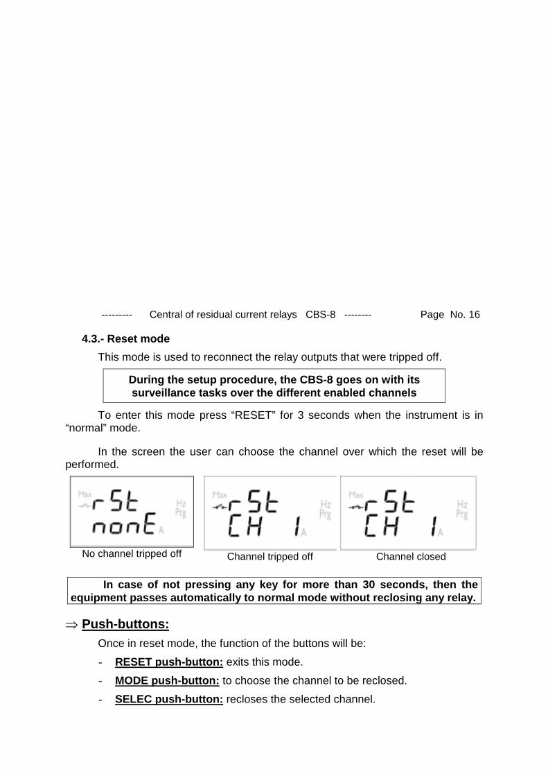
4.3.- Reset modeThis mode is used to reconnect the relay outputs that were tripped off.
During the setup procedure, the CBS-8 goes on with itssurveillance tasks over the different enabled channels
To enter this mode press “RESET” for 3 seconds when the instrument is in“normal” mode.
In the screen the user can choose the channel over which the reset will beperformed.
No channel tripped off Channel tripped off Channel closed
In case of not pressing any key for more than 30 seconds, then theequipment passes automatically to normal mode without reclosing any relay.
� Push-buttons:Once in reset mode, the function of the buttons will be:- RESET push-button: exits this mode.- MODE push-button: to choose the channel to be reclosed.- SELEC push-button: recloses the selected channel.

--------- Central of residual current relays CBS-8 -------- Page No. 17
4.4.- Setup modeThis mode is used program the CBS-8.
To enter this mode push simultaneously MODE & SELECT.
For the time in which the equipment is in setup mode, thepower lines will be permanently controlled considering the
parameters selected before entering this mode.The multipoint scanning system, CBS-8, has an external switch to protect the
modification of the setup (switch “PROG”).
� Switch “PROG”Depending on the position of this switch, the user will be enabled to:- Up (sealable position): the CBS-8 setup mode can be entered but not
modified.- Down: The CBS-8 setup mode can be accessed and the modification of
any programming parameter is enabled.
� Push-buttons:The push-buttons in this mode permit the user to execute following actions:- RESET push-button: exits without saving any modification.- MODE push-button: changes the selected menu option.- SELECT push-button: to validate the option in screen.- MODE + SELECT push-button: To start the normal operation according
to the new programming.

--------- Central of residual current relays CBS-8 -------- Page No. 18
5.- SETTING UP THE CBS-8The setup procedure of the CBS-8 is accomplished by means of several
SETUP options.
� To access the setup menu the keys MODE and SELECT must besimultaneously pressed from the normal operation mode (see 4.4.- for more details)
When accessing the SETUP, the initial screen permits the user to selectamong the channel characteristics setting or the communications settings:
P.CHA Channel configurationC.SEr Communications configuration
The selected option blinks.- The MODEkey allows to scroll over the configurable options.- The SELECT key to validate his choice.- RESET to exit the setup without storing any change.- MODE & SELECT are used to confirm the new setup and return to normal
mode.
5.1.- Channel settingOnce into the SETUP, use the keyboard to select different options and set
desired values:
...Where:
- P.CH - : indicates common user-configurable parameters- P.CH1 ... P.CH8: Single setting of each channel.
--------- Central of residual current relays CBS-8 -------- Page No. 19
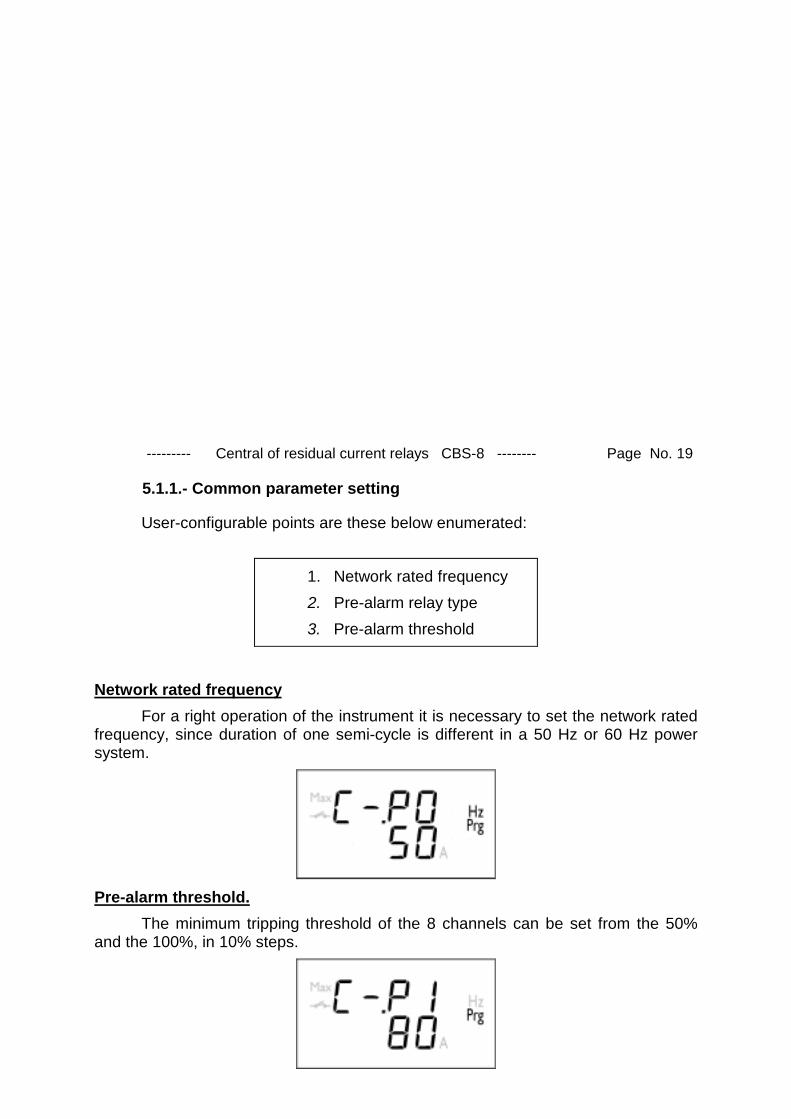
5.1.1.- Common parameter setting
User-configurable points are these below enumerated:
1. Network rated frequency2. Pre-alarm relay type3. Pre-alarm threshold
Network rated frequencyFor a right operation of the instrument it is necessary to set the network rated
frequency, since duration of one semi-cycle is different in a 50 Hz or 60 Hz powersystem.
Pre-alarm threshold.The minimum tripping threshold of the 8 channels can be set from the 50%
and the 100%, in 10% steps.

--------- Central of residual current relays CBS-8 -------- Page No. 20
Pre-alarm relay typeTwo values are available for their choice: nO for normally open outputs, and
nC for normally closed outputs.
Normally open Normally closed
5.1.2.- Channel settingEach of the 8 discrete channels of the CBS-8 must be particularly user-
programmed as below described:In case that the CBS-8 is used just as an earth leakage current meter, then
only the type of transformer connected to each channel and the tripping thresholdmust be set.
5.1.2.1.- Selection of the type of transformer connected to each channelThree values are here available for their choice:
Not used WG 30 mA - 3A WGP 300 mA - 30A

--------- Central of residual current relays CBS-8 -------- Page No. 21
5.1.2.2.- Tripping characteristicsFor these instruments to be used just as earth leakage current meter, only the
tripping threshold value must be programmed.Tripping threshold
The user must set here the current value that will define the residual currentrelay trip (output relay).
When the CBS-8 is to be used just as an earth leakage current meter (onlyvisualization functions), the user must set the maximum value of earth leakagecurrent that is to be measured (end of scale). This value is very important because ifthe user selects a value too high the instrument will lose accuracy and in case that itis too low the input will reach saturation and the measurement shown will be wrong.Therefore it should be chosen depending on each specific application.
16 different values can be chosen depending on the used transformer:30 mA ...3ª 300 mA ... 30A
30 mA 700 mA 300 mA 7 A50 mA 800 mA 500 mA 8 A100 mA 900 mA 1 A 9 A200 mA 1 A 2 A 10 A300 mA 1,5 A 3 A 15 A400 mA 2 A 4 A 20 A500 mA 2,5 A 5 A 25 A600 mA 3 A 6 A 30 A

--------- Central of residual current relays CBS-8 -------- Page No. 22
Delay timeThis is the period of time that the tripping threshold value must be exceeded
by the earth leakage current to activate the output relay of the pertinent channel.
8 different delay times can be selected:
0,02 s 0,04 s 0,06 s 0,08 s
0,1 s 0,4 s. 0,8 s 1 s
Note: when the tripping threshold is 30 mA, only a delay time of 0,02 s can bechosen.
The delay times that can be selected directly by means of the frontal keyboardof the instrument are the ones shown on the previous table. However, viacommunications a much wider range of times can be selected, up to 10 s.

--------- Central of residual current relays CBS-8 -------- Page No. 23
Type of relay outputTwo values are available for their choice to define the normal position of the
relay: nO for normally open outputs, and nC for normally closed outputs.
Normally open Normally closed
5.1.2.3.- Self-reclosing actionsFollowing outlined options will be only available in case that this option has
been previously enabled through the software “Easycomm CBS-8”“appropriatecommunication commands (MODBUS commands).
Delay time between successive reclosing actions
���� Value between 1 and 900 s

--------- Central of residual current relays CBS-8 -------- Page No. 24
Type of delay time between successive reclosing actionsThe application of delay times between successive reclosing actions gives rise
to two reclosing modes:- Normal: The delay time between successive reclosing actions is equal to the
value set by the user in the previous parameter.- Exponential: After each self-reclosing attempt, the delay time to be waited until
the next self-reclosing attempt follows this rule: trecn+1 = trec ·2n, where n standsfor the number of self-reclosing attempts occurred until the present moment, andtrec stands for the delay time set by the user in the previous parameter.
Normal Exponential
Number of self-reclosing attempts
���� Value between 0 and 10 attempts
The user can define the maximum number of self-reclosing attempts to beexecuted by the CBS-8. If this number is completed without any successful attempt,then the referred relay will keep latched until a manual or remote reset action isexecuted.
Note: if the programmed number of reconnections is 0, then the self-reclosingwill be disabled.

--------- Central of residual current relays CBS-8 -------- Page No. 25
5.2.- Communication settingWhen the user choose the option C.SEr, then the menus that permit him to
modify all those parameters related to serial communications are accessed.Following screens are successively shown in display:
Peripheral number (identification code):Peripheral number of each CBS-8 within the MODBUS communication
network.
� Peripheral No. between 1 and 255.
In this point, the key Mode executes following actions:- Short touch: The peripheral number is increased by 1- Long touch: The peripheral number is increased by 10
Baud rate:
Three baud rate values are available for their choice:4800 bauds - 9600 bauds - 19200 bauds
--------- Central of residual current relays CBS-8 -------- Page No. 26
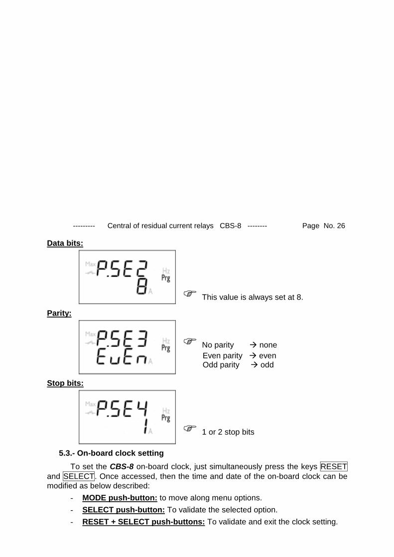
Data bits:
� This value is always set at 8.
Parity:
� No parity � none Even parity � even Odd parity � odd
Stop bits:
� 1 or 2 stop bits
5.3.- On-board clock settingTo set the CBS-8 on-board clock, just simultaneously press the keys RESET
and SELECT. Once accessed, then the time and date of the on-board clock can bemodified as below described:
- MODE push-button: to move along menu options.- SELECT push-button: To validate the selected option.- RESET + SELECT push-buttons: To validate and exit the clock setting.

--------- Central of residual current relays CBS-8 -------- Page No. 27
6.- TECHNICAL SPECIFICATIONS
Power supply : see specifications on the side of the CBS-8- CBS-8.... : Single-phase 230 V a.c. Voltage tolerance: -15 % / +20 % Frequency : 50 - 60 HzBurden .................................. 4 VAOperation temperature ......... -10º to 50 º CMeasuring circuitCurrent range: According to the associated transformer
WGxx 30 mA - 3 A WGPxx 300 mA - 30 AMeasuring mode: True RMS valueSampling time: 1250 µsPre-alarm:Delay time: 500 msHysteresis: 50%Accuracy in current: <15%Accuracy classCurrent .............................. < 5 %Test conditions :- Current transformers not included- Temperature between + 5 ºC and + 45 ºCMechanical characteristics- Case material: Self-extinguishable plastic- Connection: Metallic terminals with "posidraft" screws- Mounting: To fit onto symmetric DIN 46277 (EN 50022) rail. Possibility of screw fixing (4.2 mm ∅ passing hole for fixing).- Frontal cover: Made of lexan- Protection Assembled unit : IP 41 Terminals : IP 20- Dimensions: 140 x 70 x 110 mm (8-module size as per DIN 43 880 )- Weight: 0.560 kg

--------- Central of residual current relays CBS-8 -------- Page No. 28
Output relays characteristics- Maximum switching voltage : 250 V a.c.- Maximum switching current : 5 ASafety .............. Class III - 300 V a.c. , EN-61010
Protection against electric shock by class II double-insulation Standards: IEC 1008, IEC 1010, IEC 255-5, UNE 801-2, UNE 801-3, UNE 801-4,UNE 60730-1, UNE 61010
Dimensions :
110
140 70
45

--------- Central of residual current relays CBS-8 -------- Page No. 29
7.- SAFETY CONSIDERATIONS The user should take into account all installation instructions
indicated in sections INSTALLATION & STARTUP and TECHNICALSPECIFICATIONS of this manual.
Note that with the instrument powered on, the terminals could be dangerous totouching and cover opening actions or elements removal may allow accessingdangerous parts. This instrument is factory-shipped at proper operation condition.
8.- MAINTENANCEThe CBS-8 does not require any special maintenance. No adjustment,
maintenance or repairing action should be done over the instrument open andpowered and, should those actions are essential, high-qualified operators mustperform them.
Before any adjustment, replacement, maintenance or repairing operation iscarried out, the instrument must be totally disconnected from any power supplysource. When any protection failure is suspected to exist, the instrument must beimmediately put out of service. The instrument’s design allows a quick replacementin case of any failure.
9.- TECHNICAL SERVICEFor any inquiry about the instrument performance or If any failure happens,
please contact to CIRCUTOR’s technical service: CIRCUTOR S.A. - After-sales service Lepanto, 49 08223 - TERRASSA (BARCELONA - SPAIN) Tel - + 34 93 745 29 00 fax - + 34 93 745 29 14 E-mail : [email protected]

--------- Central of residual current relays CBS-8 -------- Page No. 30
10.- CBS-8 COMMUNICATIONS
����---- EdEdEdEd
RdRdRdRd
161718192021222324252627
A2A2A2A2
1528PowerPowerPowerPowerSupplySupplySupplySupply COMTEST 2TEST 1 RL 1 RL 2 RL 3 RL 4 RL 5 RL 6 RL 7 RL 8
A1A1A1A1
1413121110987654321
GNDGNDGNDGNDPow erPow erPow erPow erSupplySupplySupplySupply
S1S1S1S1 S1S1S1S1S1S1S1S1 S1S1S1S1S2S2S2S2 S2S2S2S2S2S2S2S2 S2S2S2S2
T2T2T2T2 T6T6T6T6T3T3T3T3 T7T7T7T7
ALARM
2A 250V
S1S1S1S1 S1S1S1S1S2S2S2S2 S2S2S2S2S2S2S2S2 S2S2S2S2S1S1S1S1 S1S1S1S1
T1T1T1T1 T5T5T5T5T4T4T4T4 T8T8T8T8(+)(+)(+)(+)
RS485RS485RS485RS485
One or some CBS-8 units can be connected to a PC. With this system we canget all the parameters in one central point of reading. The CBS-8 has a serial RS-485 output, so, if we connect more than one device to the same communication line,we have to assign to each discrete analyzer a different code or direction (from 01 to255), since the PC needs the identification of every measuring point.
10.1.- To take into account!:
- PROTOCOL: MODBUS © (Question / Answer)- CBS-8 DEFAULT CONFIGURATION: 001/9,600 / 8 bits / N / 1 bit- Available baud rates: 4,800 – 9,600 – 19,200 bauds- RS-485 Output: Terminal No. Signal
12 --------- TX + 13 --------- TX - 14 --------- GND
- The RS-485 connection will be carried out by means of a twisted andscreened cable, with a minimum of 3 wires, with a maximum distancebetween the CBS-8 and the last peripheral of 1,200 m. The CBS-8 uses aRS-485 communication bus that enables the connection of a maximum of32 devices in parallel (multi-point bus) per each single port used inthe PC.

--------- Central of residual current relays CBS-8 -------- Page No. 31
10.2.- Connection of a RS-485 network to a PC (RS-232)
A1
A2
5
12
1413
12
5 12
75
2357
32
RS-485
RS-232
CONVERTER
DB-9
RS-232 / RS-485
CBS-8
PC
CBS-8
* If you are using the RS485/232 converter with RTS control ability (code 770208),then the connection of the pin#7 in the RS-232 side is not required.

--------- Central of residual current relays CBS-8 -------- Page No. 32
10.3.- MODBUS © ProtocolThe CBS-8 apparatus can communicate by means of the MODBUS ©
protocol, as it is following described:When the CBS-8 communicates with MODBUS protocol, it uses the RTU
mode (Remote Terminal Unit ). Each 8-bits byte in a message contains two 4-bitshexadecimal characters.
The format for each byte in RTU mode is:* Code : 8-bits binary, hexadecimal 0-9, A-F
2 hexadecimal characters contained ineach 8-bits field of the message.
* Bits per Byte : 8 data bits* CHECK- ERROR Field : CRC type (Cyclical Redundancy Check).
MODBUS FUNCTIONS IMPLEMENTED IN THE CBS-8:FUNCTION 03h & 04h Reading n WORDS (16 bits-2 bytes). This function
permits to read all the parameters from the CBS-8.
FUNCTION 06h Writing one WORD (16 bits-2 bytes) into a memoryposition.
FUNCTION 10h Writing n WORDS (16 bits-2 bytes) intoconsecutive memory positions.

--------- Central of residual current relays CBS-8 -------- Page No. 33
10.3.1.- Readout registersTo read these type of registers use the 03H or 04H MODBUS function.Two kind of data is saved into the CBS-8 on-board memory:- Parameters: Involve all information provided by the CBS-8 related to
measurements and output relays status.- Logs: These records store the last 100 operations executed by the CBS-8.
Parameters:MODBUS REGISTERS HEXA-DECIMAL (longs)
ChannelDescription Unit
1 2 3 4 5 6 7 8Date* 0000-0001Residual current (mA) 0002 0003 004 0005 0006 0007 0008 0009
Output status
0=Not tripped1=Excedded2=Tripped3=Latched
000A 000B 000C 000D 000E 000F 0010 0011
Pre-alarm relaystatus
0=Diactivated1=Activated 0012
Tripping or latchingcurrent (mA) 0013 0014 0015 0016 0017 0018 0019 001A
Latest saved record 001BOperation mode 001C
switch “PROG” 0=Up1=Down 001D
Software version 001E
Pre-alarm ON 0=Diactivated1=Activated 001F 0020 0021 0022 0023 0024 0025 0026
* Date format: b0 - b5 Seconds b6 - b11 Minutes b12 - b16 Hour b17 - b21 Day of the month b22 - b25 Month b26 - b31 Year + 2000

--------- Central of residual current relays CBS-8 -------- Page No. 34
Logs in memoryRelay tripping events are recorded in the CBS-8 on-board. The structure of
this data in memory consists of 4-register blocks.The below table shows the initial and ending reading registers:
Event 0 1 2 3 4 5 6 7 8 900 0400 0404 0408 040C 0410 0414 0418 041C 0420 042410 0428 042C 0430 0434 0438 043C 0440 0444 0448 044C20 0450 0454 0458 045C 0460 0464 0468 046C 0470 047430 0478 047C 0480 0484 0488 048C 0490 0494 0498 049C40 04A0 04A4 04A8 04AC 04B0 04B4 04B8 04BC 04C0 04C450 04C8 04CC 04D0 04D4 04D8 04DC 04E0 04E4 04E8 04EC60 04F0 04F4 04F8 04FC 0500 0504 0508 050C 0510 051470 0518 051C 0520 0524 0528 052C 0530 0534 0538 053C80 0540 0544 0548 054C 0550 0554 0558 055C 0560 056490 0568 056C 0570 0574 0578 057C 0580 0584 0588 058C
The format of the recorded event (8 bytes) will be as follows:1 byte2 byte3 byte4 byte
Tripping action date
5 byte6 byte Tripping current7 byte Tripped channel8 byte Not used

--------- Central of residual current relays CBS-8 -------- Page No. 35
10.3.2.- Working registersSome actions can only be executed by means of communication commands.These operations are completed using the function for writing one register.
Channel resetQuestion
NP06030XFFFFCRCAnswer
NP06030XFFFFCRC
Where X stands for the number of the channel (1-8) to be reset (0-Allchannels).Deleting the file of event logs
QuestionNP06030EFFFFCRC
AnswerNP06030EFFFFCRC
10.3.3.- Self-reclosing featureOne of the features of the CBS-8 is the possibility of enabling the
reconnection (self-reclosing) of those channels that have been tripped off.
To enable this option the software “Easycomm CBS-8” has to be used. Thesoftware can be foung in the product package.
The instruction manual can be also found in the enclosed CD.


