
Multiple-Service Floor Boxes for Power, Communications …€¦ · 65 Recessed Service Floor Boxes...
12
64 Recessed Service Floor Boxes 664 Series Floor Box Multiple-Service Floor Boxes for Power, Communications and Data Multiple-service floor boxes deliver power, communications and data from standard conduit with no exposed service fittings. Result: Open office planning flexibility. Ideal for the modern office with workstations that have power, communications and data equipment. Power receptacles and low-voltage connections can be enclosed underfloor in either steel or cast-iron bodies. Galvanized 14-gauge steel boxes are provided with knockouts from 3/4’’ to 1-1/4’’. Cast-iron bodies have threaded openings for 3/4’’ and 1’’ conduit. Cat. No. Description Std. Ctn. 664-SC Stamped-Steel Box which Accepts Two Plates, One Duplex Plate Provided 4 664-CI Cast-Iron Box which Accepts Two Plates, One Duplex Plate Provided 4 664-S Shallow Stamped-Steel Box which Accepts Two Plates, One Duplex Plate Provided 4 When ordering a 664 Series box, the cover must be ordered separately, see page 66. For communications accessories, see page 104. Caution: When using the center side KOs, Catalogue Number 664-RP must be assembled to the box prior to installing the conduit. Engineering Data — 664 Series Cat. No. Dimensions (in.) Before Pour Adj. (in.) After Pour Adj. (in.) Maximum Capacity (cu. in.) Standard Conduit Tapping Maximum Conduit Tapping (in.) Conduit KOS Covers Sides Bottom A B C W/Bushing W/O Bushing 664-SC 3-3/4 4-11/16 10-1/4 2-1/2 3/4 24 per gang 90 total – – – (4) 1’ – 1-1/4’’ (4) 3/4 None 664-CST Series 664-CI 3-3/4 5-3/32 9-15/16 2-1/2 3/4 24 per gang 90 total (4) 3/4’’ (4) 1’’ 1 1-1/2 – – 664-CST Series 664-S 2-7/8 4-11/18 10-1/4 1-1/2 3/4 16.5 per gang 70 total – – – (6) 3/4’’ None 664-CST Series A B C • Two-compartment boxes are available in three types: stamped steel (664-SC), shallow (664-S) and cast iron (664-CI). • Durable nonmetallic covers include a steel reinforcement plate for added strength. • New! Metallic covers in solid brass and aluminum provide aesthetics and durability. • Four leveling screws enable quick leveling to desired concrete depth. • Cover flange self-levels with the finished floor for easy installation. 664-CI 664-S 664-SC
Transcript of Multiple-Service Floor Boxes for Power, Communications …€¦ · 65 Recessed Service Floor Boxes...
64
Recessed Service Floor Boxes
664 Series Floor Box
M u l t i p l e - S e r v i c e F l o o r B o x e s f o r P o w e r ,C o m m u n i c a t i o n s a n d D a t a
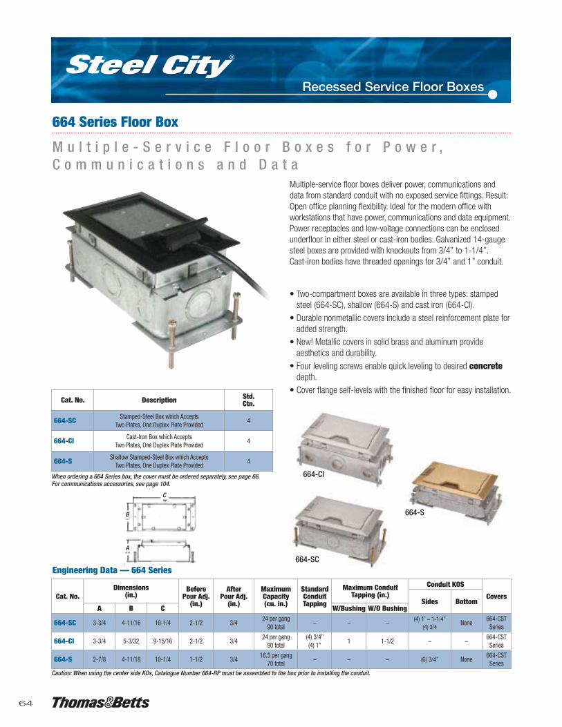
Multiple-service floor boxes deliver power, communications anddata from standard conduit with no exposed service fittings. Result:Open office planning flexibility. Ideal for the modern office withworkstations that have power, communications and data equipment.Power receptacles and low-voltage connections can be enclosedunderfloor in either steel or cast-iron bodies. Galvanized 14-gaugesteel boxes are provided with knockouts from 3/4’’ to 1-1/4’’. Cast-iron bodies have threaded openings for 3/4’’ and 1’’ conduit.
Cat. No. Description Std.Ctn.
664-SC Stamped-Steel Box which AcceptsTwo Plates, One Duplex Plate Provided
4
664-CI Cast-Iron Box which AcceptsTwo Plates, One Duplex Plate Provided
4
664-S Shallow Stamped-Steel Box which AcceptsTwo Plates, One Duplex Plate Provided
4
When ordering a 664 Series box, the cover must be ordered separately, see page 66.For communications accessories, see page 104.
Caution: When using the center side KOs, Catalogue Number 664-RP must be assembled to the box prior to installing the conduit.
Engineering Data — 664 Series
Cat. No.Dimensions
(in.)Before
Pour Adj.(in.)
AfterPour Adj.
(in.)
MaximumCapacity(cu. in.)
StandardConduitTapping
Maximum ConduitTapping (in.)
Conduit KOS
CoversSides Bottom
A B C W/Bushing W/O Bushing
664-SC 3-3/4 4-11/16 10-1/4 2-1/2 3/424 per gang
90 total– – – (4) 1’ – 1-1/4’’
(4) 3/4None
664-CSTSeries
664-CI 3-3/4 5-3/32 9-15/16 2-1/2 3/424 per gang
90 total(4) 3/4’’(4) 1’’
1 1-1/2 – –664-CST
Series
664-S 2-7/8 4-11/18 10-1/4 1-1/2 3/416.5 per gang
70 total– – – (6) 3/4’’ None
664-CSTSeries
A
B
C
• Two-compartment boxes are available in three types: stamped steel (664-SC), shallow (664-S) and cast iron (664-CI).
• Durable nonmetallic covers include a steel reinforcement plate foradded strength.
• New! Metallic covers in solid brass and aluminum provideaesthetics and durability.
• Four leveling screws enable quick leveling to desired concretedepth.
• Cover flange self-levels with the finished floor for easy installation.
664-CI
664-S
664-SC

65
Recessed Service Floor Boxes
Metallic Covers for 664 Series Floor Boxes
Lid Rotated 180º to expose Cord Opening.
Cord Opening
Cat. No. Finish Load Rating(lb.)
Std.Ctn.
664-CST-SW-BRS Solid Brass 2,250 1
664-CST-SW-ALM Solid Aluminum 2,250 1
8-3/8’’
5-1/2’’
1/4’’
1-1/8’’
664-CST-SW-BRSSolid Brass
664-CST-SW-ALMSolid Aluminum
664-CICast Iron for Slab or Grade Applications
664-SFor Shallow Concrete Applications
664-SCStamped Steel for General Purpose
MopTiteTM Covers meet UL scrub-water exclusion requirements for carpet, tile and wood.

66
Recessed Service Floor Boxes
664-S-RP 664-S-BP
Nonmetallic Covers for 664 SeriesFloor Boxes
Device Plates — 664-SC & 664-CI
664-CST-SW-BLK 664-CST-SW-BRN
664-BP 664-RP664-GP
664-CST-SW-BGE 664-CST-SW-GRY
5/32’’ Steel Top Plate on lid, carpetor tile can be glued to top plate.
Cover lid
Cover frame
Cord door locksopen or closed
MopTiteTM covers meet UL scrub-water exclusionrequirements for carpet, tile and wood.
0.188’’Flange height
5.125’’4.012’’
8.125’’ 0.845’’
Cat. No. Description Std.Ctn.
664-BP Blank Plate 4
664-GP GFCI Receptacle Plate 4
664-RP Duplex Receptacle Plate 4
Cat. No. Description Std.Ctn.
664-S-RP Duplex Receptacle Plate 4
664-S-BP Blank Plate 4
Cat. No. For Use With Std.Ctn.
664-WT 664 and 664-CI Floor Boxes 4
664-S-WT 664-S Floor Box 4
Cat. No. Colour Load Rating(lb.)
Std.Ctn.
664-CST-SW-GRY Grey 1,500 1
664-CST-SW-BRN Brown 1,500 1
664-CST-SW-BGE Beige 1,500 1
664-CST-SW-BLK Black 1,500 1
Material: Polycarbonate with 5/32’’ steel plate.(see page 65 for metallic cover options)
• Duplex receptacle face plate for 664 Series floor box foradditional power service.
• Does not include duplex.
Wire Tunnel for 664 Series• Wire tunnel for protecting electrical connections between the two
duplex receptacles when the box is used for power/powerapplication.
Caution: When using the center side KOs, all 664 plates must be assembled to the boxprior to installing the conduit.
Device Plates — 664-SA
664-S-WT664-WT

67
Recessed Service Floor Boxes
665 Series Floor Boxes: 665-SC
DeviceCompartment
3’’
5-7/8’’12-1/8’’
1-1/4’’KO
3-1/2’’2-1/2’’
3/4’’ Knockout 1-1/4’’ Knockout665-SC floor box does not include device plates or covers. Order separately.Material: Pre-Galvanized Steel.
1-1/4’’
3/4’’ KO
12-1/8’’Top View
Bottom Plate
Cat. No.Device Compartments (in.) Device
AccessArea
Std.Ctn.Length Width Height Area
665-SC 5-3/4 2-3/4 2-1/2 40 cu. in. 126 cu. in. 1
• For concrete application.
• The 665 line is an extension of the industry-leading 664 Series; our concealed service line now allows the customer to install upto four device panels in one box.
• Through the use of a unique nonmetallic wire tunnel, the installer can easily partition the power, voice/data requirements.
• Four (4) device compartments can accomodate any combination of devices. For example: (3) duplex power devices and (1) duplex telephone device, or (2) voice and data connectors and (1) GFCI device and (1) blank, etc.
• Overall height of 3-1/2’’ allows for shallow pours when needed.
• High-Strength polycarbonate cover with a 5/32” steel plateassures structural integrity.
• Metallic Covers also available in solid brass and aluminum.
• Four-side feed-through allows installer to feed through power or data/comm service from any orientation.
• Nonmetallic wire tunnels aesthetically clean. Full-width tunnel provides maximum feed-through capacity; nonmetallic material prevents conductor damage.
• Total access area of 126 cu. in. allows for friendly installation of workstation cables.
• Contains 28 knockouts (16 – 1-1/4’’ and 12 – 3/4’’ KOs) thatprovide increased flexibility when installed.
• This CSA Listed, stamped-steel floor box can be installed withThomas & Betts voice and data connector products.
• Four 2-1/2’’ levelling screws provided with all boxes.
• Device panels ordered separately.

68
Recessed Service Floor Boxes
665-SC floor box does not include device plates or covers. Order separately.
Cat. No.Device Compartments (in.)
Device Access Area Std.Ctn.Length Width Height Area
665-CI 5-3/4 2-3/4 2-1/2 40 cu. in. 126 cu. in. 1
665 Series Floor Boxes: 665-CI
C a s t I r o n f o r S l a b - O n - G r a d e A p p l i c a t i o n s
The new Steel City® 665 Cast Iron Floor Box provides a high-capacity power and data solution for ground-floor installations.This 4-gang recessed-service floor box is ideal for concreteslab-on-grade applications. Removable voltage dividers enableusers to customize wiring configurations by feeding two or moreadjacent compartments with a single conduit. Aesthetic coversfeature a recess to accept floor covering to match the surroundingfloor.
• 4-gang, recessed service for a high-capacity aesthetic floor-box solution.
• Removable voltage dividers between compartments enablea single conduit to feed two or more adjacent compartments.
• Heavy-duty, nonmetallic covers with steel-reinforcement plates are available in a wide variety of colours to match any decor (black, grey, brown and beige).
• Metallic Covers.
• Separate cord door in the cover latches firmly in the open positionto prevent damage to cables.
• MopTiteTM covers meet UL scrub-water exclusion requirements forcarpet, tile and wood.
• Largest cubic-inch capacity of any cast iron recessed 4-gangfloor box.
• Inline 1-1/4’’ hubs allow high-capacity straight runs forcommunication wiring.
• Material: Box – Cast IronCover – Polycarbonate with steel reinforcement plate.
• Listing: CSA and UL Listed.
Specifications
3/4’’NPT
3/4’’NPT
3/4’’NPT
5/8’’
2.50’’
Access6-5/8’’
3/4’’NPT
1-1/4’’NPT
1-1/4’’NPT
1-1/4’’NPT
7.94’’Inside Square
14.81’’
14.81’’
Top View
Side View

69
Recessed Service Floor Boxes
Cat. No. Description Std.Ctn.
665-AV2 4-Compartment Recessed Service Floor Box with 2’’ KOs for AV Applications 1
665 Series Floor Boxes: 665-AV2
2 K O s f o r A u d i o V i s u a l A p p l i c a t i o n s•For concrete application.
•2 KOs enable pre-terminated AV cables and connectors to be pulled directly through the conduit.
•Accepts standard 665 Series covers and device plates for power, voice, data and audio visual connections.
•NEW! Decora® style adapters allow voice, data and AV connectors to be mounted in a standard GFCI device plate.
•NEW! Keystone style voice, data and AV connectors meet a wide range of low-voltage applications. All connectors are recessed for flush mounting in floor box applications.
•NEW! Device plates are available that accept Extron® MAAP platesto accomodate any AV requirements (Extron® MAAP platespurchased from an authorized Extron distributor).
•NEW! Metallic covers provide a durable, aesthetic installation,including industry-exclusive solid brass covers (not painted or plated, aluminum also available).
665-AV2 floor box does not include device plates or cover. Order separately. (see page 70).Decora® is a registered trademark of Leviton Manufacturing Co., Inc.Extron® is a registered trademark of RGB System, Inc.For communication accessories, see page 104.
12-1/2’’
14’’4-1/2’’
3-9/16’’ 2’’ KO
1-25/32’’
1/4’’ KO
3/4’’ KO
Engineering Data — 665-AV2
Cat. No.Before
Pour Adj.(in.)
AfterPour Adj.
(in.)
Compartment Size & Capacity(Qty. = 4)
Conduit KOs(in.)
Length (in.) Width (in.) Height (in.) Volume Sides Bottom
665-AV2 2-1/2 3/45-3/45-3/4
3-3/42-3/4
3-3/83-3/8
72 cu. in.52 cu. in.
(4) 2(8) 1-1/4(8) 3/4
(2) 2(2) 1-1/4(4) 3/4
Decora® Adapters and Keystone Inserts for GFCI Device Plates.
70
Recessed Service Floor Boxes
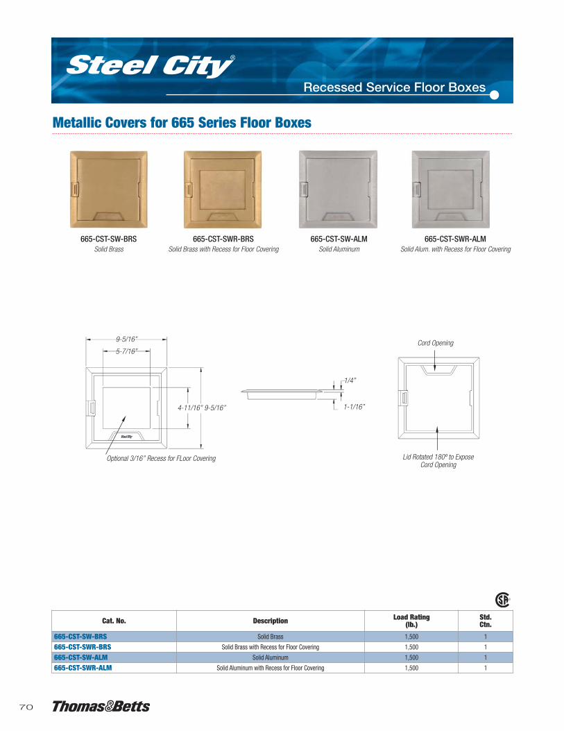
Metallic Covers for 665 Series Floor Boxes
Optional 3/16’’ Recess for FLoor Covering Lid Rotated 180º to ExposeCord Opening
Cord Opening
Cat. No. Description Load Rating(lb.)
Std.Ctn.
665-CST-SW-BRS Solid Brass 1,500 1
665-CST-SWR-BRS Solid Brass with Recess for Floor Covering 1,500 1
665-CST-SW-ALM Solid Aluminum 1,500 1
665-CST-SWR-ALM Solid Aluminum with Recess for Floor Covering 1,500 1
1/4’’
1-1/16’’4-11/16’’ 9-5/16’’
9-5/16’’
5-7/16’’
665-CST-SW-BRSSolid Brass
665-CST-SWR-BRSSolid Brass with Recess for Floor Covering
665-CST-SW-ALMSolid Aluminum
665-CST-SWR-ALMSolid Alum. with Recess for Floor Covering

71
Recessed Service Floor Boxes
Nonmetallic Covers for 665 Series Floor Boxes
665-CST-SW-GRYGrey Nonmetallic Cover
665-CST-SW-BGEBeige Nonmetallic Cover
665-CST-SW-BRNBrown Nonmetallic Cover
9’’
7-7/8’’
5/32’’ Steel Top Plate on Lid. Carpetor Tile can be glued to Top Plate
7-7/8’’
3/16’’
1-1/16’’
Polycarbonate Flange & Lid
6-1/2’’’
6-1/2’’’
5-3/4’’
1-5/16’’
2-5/8’’
1’’
2-1/8’’
1-1/4 Dia. Hole
Cat. No. Colour Description Std. Ctn.665-CST-SW-BLK Black
Nonmetallic Cover for665 Series Floor Boxes
1
665-CST-SW-GRY Grey 1
665-CST-SW-BGE Beige 1
665-CST-SW-BRN Brown 1
Material: Polycarbonate with 5/32’’ steel plate.Furnished with (4) #8-32 x 5/8’’ mounting screws.For color samples, contact your Regional Sales Office.
Cat. No. Description Std. Ctn.665-RP Duplex Plate for 665 Series 4
665-GP GFCI Plate for 665 Series 4
665-BP Blank Plate for 665 Series 4
665-6RJ Data plate for 665 Series, Accepts 6 Keystone Jacks 4
665-WT Replacement Wire Tunnel for 665-SC & 665-AV2 4
665-STEL* Telephone/data Plate for 665 4
Each box requires (4) device plates. Material: Pre-galvanized steel.
9’’
665-WT665-6RJ
665-BP
665-STEL
665-RP
665-GP
Devices Plates and Accessories for 665 Series Floor Boxes
665-6RJData Plate for 6Keystone Jacks
665-GPGFCI Plate
665-RPDuplex Plate
665-WTWire Tunnel for 665-AV2 feeds multiplecompartments from a single conduit(one included with each 665-AV2)
665-BPBlank Plate
Cover Lid
Cover Frame
3/16’’ Deep Recessfor Floor Covering
Cord DoorLocks Openor Closed
*CSA non applicable.
665-CST-SW-BLKBlack Nonmetallic Cover

72
Recessed Service Floor Boxes
Cat. No. Description Std. Ctn.667-SC Four-Gang Recessed Floor Box 4
Supplied with (1) 667-2RP for 2 duplex receptacles and (1) 667-BP Blank Plate. For coversand other device plates, see page 73.For communications accessories, see page 104.
• For concrete application.
• Largest capacity concealed-service floor box on the market.– Four “double-gangs” allow for two duplex receptacles per gang,
for a total of eight receptacles per box.
– Each gang has 40 cu. in. of capacity.
– Box interior has 128 cu. in. of capacity.
• Standard box configuration is for up to eight power and/orlow-voltage devices.– Box design allows for feed-through cabling for power and
low-voltage conductors.
• Shallow design.– 3’’ overall height is ideal for renovations and upper level floor
installations.
• Full line of low-profile covers.– Utilizes same quality cover as AFM-8 Access Floor Module.
– High-strength polycarbonate.
– Steel reinforced for added durability.
– Two receptacle cable exit ports.
– 64 sq. in. opening provides easy access to device panels.
– 1/4’’ recess for carpet/tile insert.
– Available in grey, black, brown and beige.
• Box is manufactured with (1) 3/4’’, (3) 1’’ and (1) 1-1/4’’ KOsper gang.– This includes a 1’’ and 1-1/4 KO located in thebottom.
• Full complement of device panels.– Device panels available with one or two duplex openings, one
or two GFCI openings, six standard “keystone” with Omni 110bezels and blanks.
• Provided with leveling legs and base feet.– Base feet can be attached to form preventing box movement
during concrete pour.
– Leveling legs provide up to 1-1/2’’ pre-pour adjustment.
• Manufactured from 14-gauge pre-galvanized steel.– Quality construction provides added durability and rust
protection.
• MopTiteTM covers meet UL scrub-water exclusion requirements forcarpet, tile and wood.
667-2RPDevice Panel
(included)
1-1/4’’ KO
13’’
2’’
1’’ K.O.
3/4’’ K.O.
9-3/4’’
3’’
1’ KO
667-BPDevice Plate(included)
Leveling Screws andBase Feet (included)
Floor Box Bottom
Floor Box Top
667-SC Floor Box

73
Recessed Service Floor Boxes
Cat. No. Description Std.Ctn.
667-BP* Blank Device Panel 4
667-RP* Single Duplex Receptacle Plate 4
667-2RP* Device Panel for 2 Duplex Receptacles with Duplex KOs 4
667-1G Device Panel for 1 GFCI Receptacle 4
667-2G Device Panel for 2 GFCI Receptacles 4
667-6RJ** Device Panel for 6 Keystone Data Jacks 4
667-CST-SW-GRY* Cover and Flange – Grey 4
667-CST-SW-BLK* Cover and Flange – Black 4
667-CST-SW-BRN* Cover and Flange – Brown 4
667-CST-SW-BGE* Cover and Flange – Beige 4
**For data connectors and adapters, see pages 108 – 109.New MopTiteTM Covers exceed UL scrub-water exclusion requirements.
667-CST-SW-XXX
5/32’’ Steel Top Plate on Lid Carpet or Tile.Can Be Glued to Top Plate. 0.188’’
Flange Height
1.063’’
Cover Lid
Cord Door Locks Open orClosed
Cover Frame
9.54’’ Square10.63’’ Square
667-1G
667-BP
667-RP
667-2RP
667-2G
667-6RJ
*Not CSA Certified.

74
Recessed Service Floor Boxes
668-S Ultra-Shallow Floor BoxThe new 668-S Ultra-Shallow Floor Box from Thomas & Bettsprovides a high-capacity power and data solution for shallowconcrete floors. The low-profile 4-gang box is constructed ofgalvanized stamped steel. Removable voltage dividers enable usersto customize wiring configurations by feeding two or more adjacentcompartments with a single conduit. Metallic covers with durablepowder-coat finish are designed to match any decor, while optionaledge trims enable covers to be mounted completely flush with thefloor in tile or wood floor applications.
• Low profile (2-1/2’’ height) for shallow concrete pours.
• 4-gang, recessed service for a high-capacity, aesthetic floor box solution.
• Stamped-steel box construction.
• Removable voltage dividers between compartments enablea single conduit to feed two or more adjacent compartments.
• Metallic covers feature durable powder-coat paint to match any decor (black, grey, brown and beige).
• Heavy-duty cord door in the cover latches firmly in the openposition to prevent damage to cables.
• Optional tile trim enables flush mounting for tile and wood floorapplications.
• MopTiteTM covers meet UL scrub-water exclusion requirements forcarpet, tile and wood.
• Largest cubic-inch capacity of any shallow, recessed 4-gangfloor box.
• Additional KOs (up to 2’’) on the bottom of the box enableinstallation flexibility.
• Custom device panels are available – contact your Regional SalesOffice about these offerings.
• Material: Box – Galvanized SteelCover – Die-Cast Zinc.
• Listing: CSA and UL Listed.
Specifications
Cat. No. Description Std. Ctn.668-S Shallow, concealed service Floor Boxes 4
For covers and other device plates, see page 75.For communications accessories, see page 104.
Top View
Top View – Compartment LayoutNote: shown with Top Plate Removed.
Side View
13.25’’
15.25’’
55 cu. in. compartment2-places
41 cu. in. compartment2-places
Ground screw in eachcompartment
Removable voltagedivider 4-places
1’’ knockout2-places on bottom
2.00’’
1’’ knockout4-places each side
3/4’’ knockout1-place
each side
2 to 1-1/2’’knockout
2-places on bottom
9.69’’insidesquare
11.82’’ insidesquare
3/4’’ knockout4-places on bottom

75
Recessed Service Floor Boxes
Covers & Tile Trims for 668-S Floor Box
Cover
Section A-A
Edge Trim
0.125’’ Flange
0.312’’
9.50’’Square
11.04’’Square
11.63’’Square
Standard mounting configuration: Flange on cover overlapscarpet, tile or wood floors.
Flush mounting configuration. Optional trim ring allowscover to be mounted flush with tile or wood floors.
Cat. No. Description Std. Ctn.668-CST-ALM Metal Cover – Aluminum Powder Coat 1
668-CST-BRS Metal Cover – Brass Powder Coat 1
668-CST-BLK Metal Cover – Black Powder Coat 1
668-CST-BRN Metal Cover – Brown Powder Coat 1
668-CST-BGE Metal Cover – Beige Powder Coat 1
Cat. No. Description Std. Ctn.668-TRIM-ALM Edge Trim – Aluminum Powder Coat 4
668-TRIM-BRS Edge Trim – Brass Powder Coat 4
668-TRIM-BLK Edge Trim – Black Powder Coat 4
668-TRIM-BRN Edge Trim – Brown Powder Coat 4
668-TRIM-BGE Edge Trim– Beige Powder Coat 4
Cat. No. Description Std. Ctn.668-S-1RP Single-Gang Duplex Plate 1
668-S-1G Single-Gang GFCI Plate 1
668-S-BP Blank Plate 1
668-TRIM-ALM668-CST-BLK
668-S-1RP
668-CST-BRS 668-TRIM-BGE 668-TRIM-BLK 668-TRIM-BRS
Device Plates for 668-S FLoor Box
668-S-1G 668-S-BP 668-S-6RJ 668-S-6PAN 668-S-6ORT 668-S-6AVA
Cat. No. Description Std. Ctn.668-S-6RJ Data Plate – 6 Keystone Jacks 1
668-S-6PAN Data Plate – 6 Panduit® Jacks 1
668-S-6ORT Data Plate – 6 Ortonics® Jacks 4
668-S-6AVA Data Plate – 6 Avaya® Jacks 4CSA non applicable.
CSA non applicable.


