Super Sized Strikes: Nonunion Strikes Can Burn Unprepared Employers
Upload
srinivas80Category
view
41download
0
5/13/2018 Multiple Re-Strikes Phenomenon When Using Vacuum Circuit - slidepdf.com
http://slidepdf.com/reader/full/multiple-re-strikes-phenomenon-when-using-vacuum-circuit 1/8
Multiple Re-Strikes Phenomenon when Using Vacuum Circuit
Breakers to Start Refiner Motors
J.P. Eichenberg, QUNO Corporation, Thorold, Ontario, Canada
H. Hennenfent, Avenor Inc., Thunder Bay, Ontario, CanadaL. Liljestrand, ABB Corporate Research, Vaster&, Sweden
Abstract - 15 kV class vacuum circuit breakers have
become the most popular method of starting large chip
Refiner synchronous motors. Multiple re-strikes, can
occur in vacuum circuit breakers and may cause
transient overvoltages at the motor terminals. Thiscondition damages motor stator windings.
The paper will describe multiple re-strikes in vacuumcircuit breakers and how they are measured. It will
also discuss the experience at Avenor's Canadian pulp
and paper mills in Gold River, British Columbia and
Thunder Bay, Ontario and at the QUNO mill, Thorold,
Ontario, Can ada . Included are modifications
recommended t o protect the Refiner motors from
further damage.
I. INTRODUCTION
At the G old River mill, inter tum insulation failures in
the stator windings of Refmer synchronous motors have
occurred. This type of failure indicates that fast voltage
transients could be the cause, although the motors were
protected with both surge arresters and surge capacitors at
the motor terminals.Experience with 15 kV class vacuum circuit breakers
has shown that a large number of fast voltage transients
caused by multiple re-strikes can occur. At Gold River,
measurements were performed during all possible motorcircuit breaker operations to verify the assumption thatmultiple re-strikes were the possible cause for the
insulation failure.
Multiple re-strikes were found, causing bipolar vol
steps of 68 kV peak to peak (from -28 kV to +40 kV), whic
close to twice the surge arrester protective level. Undam
surge capacitors were found to take part in the m ultiple re-s
process.Surge arresters protect the main insulation with respec
ground but not the inter turn insulation of the stator windThis is due to a non-uniform voltage distribution across
winding for fast voltage transients.
Results show that it is not possible to protect against
transients caused by multiple re-strikes - instead multipl
strikes should be preven ted. Resistor s were installed in swith the existing surge cap acitors to prevent m ultiple re-strThe effect of the resistors was verified by me asurements. W
the resistors, no multiple pre-strikes or re-strikes were obserBecause of the Gold River experience [ 6 ] , sim
measurements were performed at Avenor, Thunder Bay [7 ]
QUNO, Thorold [8]. Synchronous motors stator insulafailures had occurred at QUNO but not at Thunder Bay.
11. MULTIPLE PRE- AND RE-STRIKES
An important characteristic of vacuum circuit breake
their ability to interrupt high frequenc y currents. A oscillating current can appear through the breaker contac
pre-strikes when closing and at re-strikes when opening
breaker contacts.
SYNCHRONOUMOTOR
ABLESACUUM
BREAKER -
T 1 1T I T I T I 1
I I
1 1 1 A A A A A A A 1- 7 - - -MOTOROURCE CAPACITANCE1 CABLE CAPACITANCE SURGE ARRESTERS
INDUCTANCUS INDUCTANCE - AND INDUCTANCE DAMPING RESISTORS
SURGE CAPACITORS
Fig. 1. Reduced equivalent circuit of the 13.8 kV bus, vacuum breaker, cables and motor
0-7803-4785-4/98/$10.00 @ 1998 IEEE 266

5/13/2018 Multiple Re-Strikes Phenomenon When Using Vacuum Circuit - slidepdf.com
http://slidepdf.com/reader/full/multiple-re-strikes-phenomenon-when-using-vacuum-circuit 2/8
The frequency (f;,) of the high frequency current The pre-strike process is repeated each time abreakdown occurs. This way a num ber of pre-strikesoccur before the contacts reach galvanic contact. Thenumber o f pre-strikes, o r the time betw een two pre-strikes
at a breaker closing, is determined by the rise time of the
recovery voltage across the breaker and contact speed.The rise time is given by the resonance circuit formed by
the load inductance (motor winding) and the load (motorside) capacitance (surge capacitors).
through the breaker is determined by the capacitances (C )
and inductances ( L ) on both the bus side and the motorside (load) of the motor circuit breaker, Fig. 1.
1
The frequency cf;,) is typically in the order of somehundred kHz.
The conditions of multiple pre-strikes and re-strikes
are the presence of a high frequency current and a breaker
that is able to interrupt the current [ l, 21. Both multiple
pre-strikes and re-strikes give rise to fast voltage
transients; however, extremely high voltages only occur at
multiple re-strikes.
Multiple pre-strikes
During closing of a vacuum circuit breaker, the distancebetween the contacts decreases. When the distance issmall enough with respect to the voltage across the breaker
contacts, a breakdown will occur, igniting an arc. The
power frequency current through the breaker will increase
from zero. Norm ally the arc will burn until the contacts
have reached galvanic contact. Howev er, depending on
the circuit parameters, a fast oscillating current can ap pear.The fast oscillating current will be superimposed on
the p ower fi-equency current, Fig. 2 . At the instant whenthe sparkover occurs between the contacts, the power
frequency current approaches zero. The current throughthe breakers will then be equal to the fast oscillating
current. If this current contains zero crossings the breaker
will interrupt the arc. The voltage across the breaker
contacts will rise. and a new breakdown can occur.
- C a l c u l a t e d c u r r e n t s t h r o ug h breaker
I0 50 10 0 150 200 250 300 350
T i m e (us1
Fig. 2 . Calculated current through the vacuum circuitbreaker when the breaker is closed, with and withoutdamping resistors.
The frequency of the recovery voltage is in the order
of 7 to 10 kHz.
In a three-phase system, if pre-strikes occur, they can
be observed at every closing of a breaker. When the
distance between the breaker contacts is small, there isalways one phase w ith high voltage acro ss the contacts.
Multiple re-strikes
Multiple re-strikes can occur when a vacuum breaker
opens. If pre-strikes are observed, the conditions that can
cause mu ltiple re-strikes are fulfilled. Wh ile pre-strikes
can occur at every closing of the breaker, multiple re-
strikes can only occur during a sma ll time wind ow of each
60-Hz cycle.When a breaker starts to open, just before a current
zero crossing of the power frequency, a re-strike mayoccur. The cause is that the distance between breakercontacts is too small to withstand the recovery voltage. If
a new arc is ignited at the re-strike, the arc will burn untilthe next current zero crossing of the 60 Hz power
frequency. At the second current zero crossing, the
distance between the contacts is large enough to withstand
the recovery voltage, and no second re-strike will o ccur.
When vacuum circuit breakers are used, and if the first
re-strike gives rise to a fast oscillating current with zero
crossing, the breaker will interrupt the current and multiplere-strikes will follow. Howev er, if there are no current
zero crossings the vacuum breaker will o nly re-strike once.Unlike pre-strikes, the distance between the breakercontacts increases with every re-strike, followed by an
increasing breakdown v oltage across the contacts.The voltage at the motor side will increase at every re-
strike due to the oscillation of the voltage at the load side
and the bus side of the vacuum circuit breaker. Both the
breakdown voltage of the breaker contacts and the voltageat the load side of the breaker increase for every re-strike.
If the voltage across the breaker contacts increases fasterthan the breakdown voltage, another re-strike is possible,resulting in a higher voltage at the load side o f the breakerthan w ith the previous re-strike.
267

5/13/2018 Multiple Re-Strikes Phenomenon When Using Vacuum Circuit - slidepdf.com
http://slidepdf.com/reader/full/multiple-re-strikes-phenomenon-when-using-vacuum-circuit 3/8
To observe multiple re-strikes, a numb er of openings
of the breaker have to be p erformed to hit the time windo w
just before a current zero crossing.
Virtual current chopping
Virtual current chopping is caused by an interactionbetween two phases, dependent upon the capacitive
coupling between the phases. Virtual current chopping can
cause multiple pre-strikes and re-strikes.
A pre-strike in the first closing phase ignites an arc in
that phase. If no fast oscillating current exists, the arc wi!lburn until the breaker contacts are closed. How ever, a pre-
strike in the next closing phase will cause a currenttransient. Depend ing on the capacitive coupling between
the phases, part o f the current transient in the seco nd phase
may flow through the first closing breaker contacts. Thiscauses a curren t zero crossing. The zero crossing can
interrupt the arc, resulting in a pre-strike in one phase that
can interrupt an arc in another phase. The interruptedphase will pre-strike again when the voltage across the
breaker contacts has exceeded the breakdown voltage.
This new pre-strike can again interrupt the arc in another
phase.Conversely, re-strikes occur between two phases when
circuit breaker contacts are opening
111. PREVENTION PROCEDURES
Multiple re-strikes should be prevented because it is not
possible to protect the motor stator winding against the
transients caused by them. To prevent both pre-strikes andre-strikes the fast oscillating current should be damped, sothat no current zero crossing of the fast oscillating current
will occur (Fig. 2) . A resistor connected in series witheach existing surge capacitor will damp the oscillatingcurrent. It is importa nt that thc R C-com bination is locatedat the end of the motor cable at the motor terminals, to
avoid reflections at the motor.The value of the resistance i s important. A resistance
chosen equal to the surge impedance of the cable [2] will
prevent reflections appearing at the motor terminals
causing current zero crossings throug h the breaker. The
resistors must have low induc tance. At Gold River, 35 and
50i2 resistors eliminated the pre-strikes; when using 1 15 i2resistors, pre-strikes were observed.
The losses in the cable and the ground wires at
frequencies and the inductance of the ground wire influence on the shape of the high frequency cu
through the breaker during re-strikes. The se paramand their influence are difficult to estimate. Therefore
recommended to verify the selected resistancemeasuremcnts.
IV . MEASUREMENTS
The sam e type of m easurements was performed at all
mills. The purpose was to investigate whe ther
conditions for multiple re-strikes were fulfilled withtype of motor breaker operation. If the conditions
fulfilled in at least one ca se the effect of damping resi
should be verified for all possible cases of motor bre
operations. The following cases were recorded:
1.2.
3.
speed is reached).
Start of a synchronous motor.Stop of a motor at synchronous speed.
Stop of a motor shortly after start (before synchro
The cases above were performed both with atone other motor running and with no other motor run
This is due to the influence of the other motor s
capacitors on the capacitance of the bus side of
breakers. If the capacitance at the bus side is much
than the capacitance of the surge capacitors, a m
connected to the bus will increase the capacitance a
bus side.
If there is a risk of multiple re-strikes occurring,most likely to occur in the third case w hen interruptin
starting current. To avoid unnecessary stress on the m
insulation, it is not recommended to perform thiswithout the damping resistors. With damping resist
number o f starts must be performed to find a case w hevacuum circuit breaker is re-striking. If a re-strike oc
it must not he followed by mor e re-strikes. If only on
strike is measured, the effect of the damping resisto
the high frequency current is verified.
268
5/13/2018 Multiple Re-Strikes Phenomenon When Using Vacuum Circuit - slidepdf.com
http://slidepdf.com/reader/full/multiple-re-strikes-phenomenon-when-using-vacuum-circuit 4/8
VACUUM SURGE SURGE SYNCHRONOUS MOTOR
BREAKER ARRESTERS CAPACITORS STATOR W INDINGSX I - -1 - 1 - 1 -
I T I T I T -I
CABLES VOL T AGEDIVIDERS
0 0 bkY:Es 1000:1
- - - -- t t t
TO TRANSIENT RECORDER
Fig. 3. Typical measuring circuit at 13.8 kV.
Measuring equipment
The voltages were measured between the three-stator
connections (across the surge capacitors) and the closest
ground wire con nection at the motor terminals.The voltages were measured using resistor type
voltage dividers that are able to withstand high voltagesand have high thermal load capabilities (Fig. 3). The
dividers have a typical rise time of 100 nanoseconds withthe actual cable length. The voltage dividers were placed
as close as possible to the motor terminals. The voltages
were recorded with a transient recorder with 8-bit
resolution. Voltage range was f 100 kV and the sampling
frequency 10 MHz. The time window was set to 20
milliseconds requiring 200000 samples per record.The power supply to the transient recorder was
connected through an isolation transformer.
QUNOGold River
Thunder Bay
8,000 HP , 1-conductor per phase
16,000 HP, 2-conductors per phase
25,000 HP, 3-conductors per phase
The length of the cables between the transformer andthe 13.8 kV bus influences the capacitance of the bus sideof the vacuum circuit breakers. The number of conductors
per phase influences the capacitance to ground and thecapacitance between the phases at the motor side of thebreakers. Also, the surge impeda nce is different.
Th e capacitances a t both sides of the breaker influence
the high frequency current through the motor breakers at
pre-strikes and re-strikes.
The results are illustrated with a n example of multiple
pre-strikes and re-strikes without damping resistors (A).
The effect of damping resistors (B and C), is shown with aclosing of the breaker, (Case 1) and with an interruption of
a motor start (Case 3).
Measured ResultsA. Without damping resistors
Multiple pre-strikes were recorded at all three mills,
indicating that the conditions for multiple re-strikes were
fulfilled. The results from the three cases of motor breaker
operations are divided into three categories:
A . Without damping resistorsB. With damping resistors and with at least one other
synchronous motor runningC. With damping resistors and with no other synchronous
motor running.
Differences between the high frequency properties ofeach 13.8 kV system in the mills were found. At Gold
River the distance between the transformer secondary
terminals and the 13.8 kV sw itchgear bus was
approximately 200 meters. At QUNO and Thunder Bay,
the distance was only about 20 meters.The motors were connected to the 13.8 kV switchgear
bus through 3-conductor cables and vacuum circuitbreakers in each mill. How ever, the motor horsepow er andnumber of conductors per phase were different.
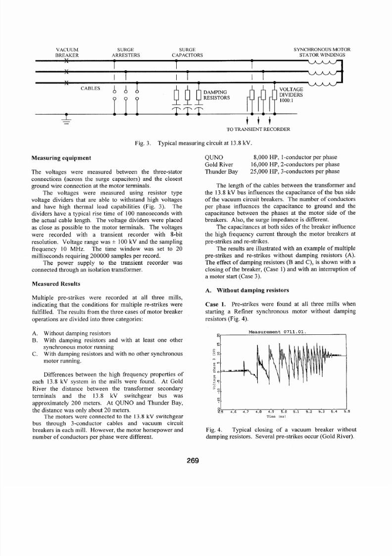
Case 1. Pre-strikes were found at all three mills when
starting a Refiner synchronous motor without damping
resistors (Fig. 4) .
Measurement 0711.01.0
? I , , . , , , . , I0
y.5 4.6 4. 7 4.8 4.9 5 .0 5.1 5. 2 5.3 5. 4 5.5
Time l m s )
Fig. 4.
damping resistors. Several pre-strikes occur (Gold River).Typical closing of a vacuum breaker without
269
5/13/2018 Multiple Re-Strikes Phenomenon When Using Vacuum Circuit - slidepdf.com
http://slidepdf.com/reader/full/multiple-re-strikes-phenomenon-when-using-vacuum-circuit 5/8
Case 2. Stop of a motor at synchronous speed showed no
over voltages. Whe n the breakers are opened with the
motor running at synchronous speed, the motor will act asa generator mainta ining the voltage at the motor side of thebreaker. Ther e will only be a very small and slow
recovery voltage across the breaker.
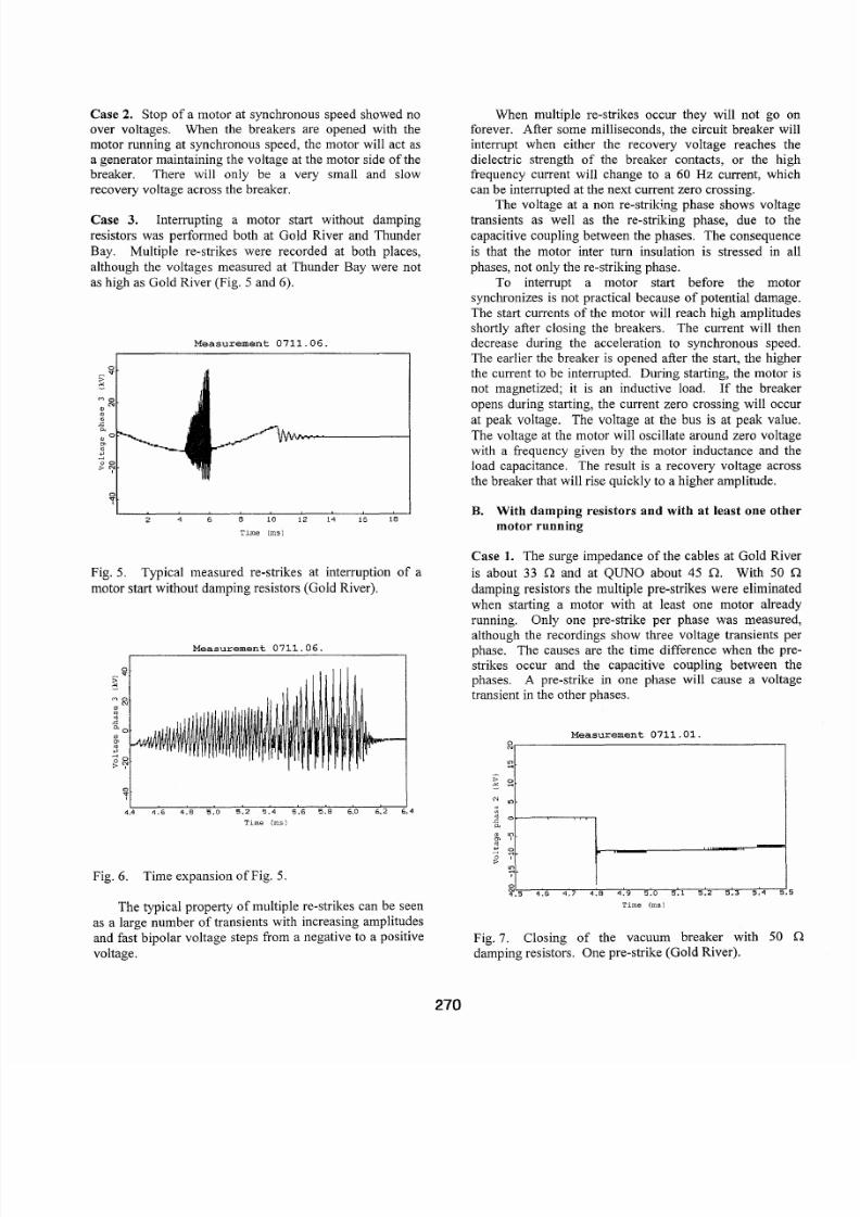
Case 3. Interrupting a motor start without damping
resistors was performed both at Gold River and Thunder
Bay. Multiple re-strikes were recorded at both places,
although the voltages measured at Thunder Bay were not
as high as Gold River (Fig. 5 an d 6).
Measurement 0711.06.
I I
I I2 4 6 8 10 12 14 16 18
Time (msl
Fig. 5.
motor start without da mpin g resistors (Gold River).
Typical measured re-strikes at interruption of a
Measurement 0711.06
I I4.4 4 .6 4 .8 5.0 5.2 5.4 5.6 5.8 6.0 6.2 6.4
Time (msl
Fig. 6. Time expansion of Fig. 5.
The typical property of m ultiple re-strikes can be seen
as a large number of transients with increasing amplitudes
and fast bipolar voltage steps from a negative to a positive
voltage.
When multiple re-strikes occur they will not goforever. After some milliseconds, the circuit breaker winterrupt when either the recovery voltage reaches dielectric strength of the breaker contacts, or the h
frequency current will change to a 60 Hz current, whcan be interrupted at the next current zero crossing.
The voltage at a non re-striking phase shows volttransients as well as the re-striking phase, due to
capacitive coupling betw een the phases. The conseque
is that the motor inter turn insulation is stressed in
phases, not only the re-striking phase .
To interrupt a motor start before the mo
synchronizes is not practical because of potential dama
The start currents of the motor will reach high amplitushortly after closing the breakers. The current will t
decrease during the acceleration to synchronous speThe earlier the breaker is opened after the start, the higthe current to be interrupted. During starting, the moto
not magnetized; it is an inductive load. If the brea
opens during starting, the current zero crossing will ocat peak voltage. The voltage at the bus is at peak va
The voltage at the motor will oscillate aro und zero v olt
with a frequency given by the motor inductance and load capacitance. The result is a recov ery voltage ac
the breaker that will rise quickly to a higher amplitude.
B. With damp ing resistors and with a t least one otmotor running
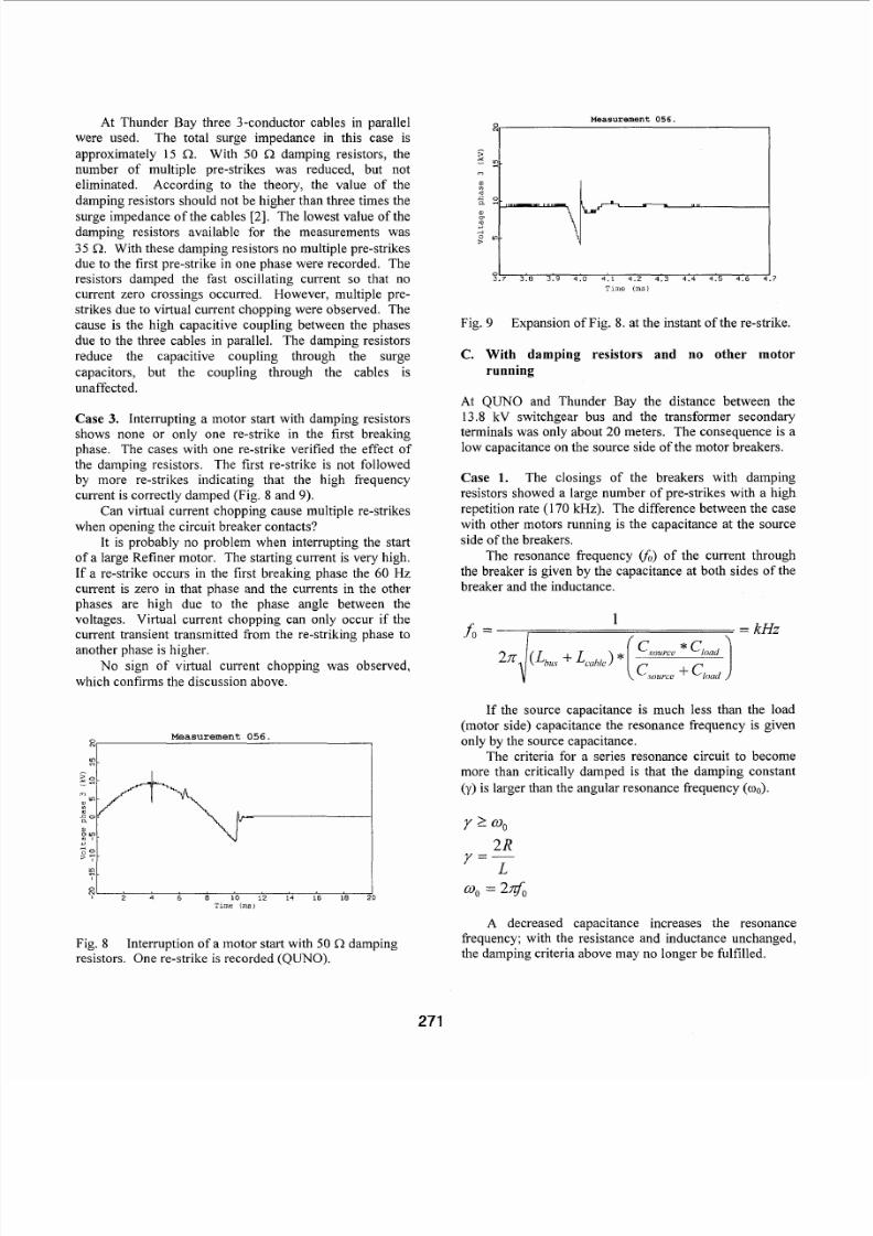
Case 1. The surge impedance of the cables at Gold Ri
is about 33 Q and at QUNO about 45 Q. With 50
damping resistors the multiple pre-strikes were elimina
when starting a motor with at least one motor alre
running. Only one pre-strike per phase was measu
although the recordings show three voltage transients phase. The causes are the time difference when the
strikes occur and the capacitive coupling between phases. A pre-strike in one phase will cause a volt
transient in the other phases.
Measurement 0711.01.
"
::4! 5 4 . 6 4.7 4 .8 4 .9 5.0 5. 1 5. 2 5.3 5. 4
I
Time (msl
Fig. 7 . Closing of the vacuum breaker with 50
damping resistors. One pre-strike (Go ld River).
270
5/13/2018 Multiple Re-Strikes Phenomenon When Using Vacuum Circuit - slidepdf.com
http://slidepdf.com/reader/full/multiple-re-strikes-phenomenon-when-using-vacuum-circuit 6/8
At Thunder Bay three 3-conductor cables in parallelwere used. The total surge impedanc e in this case is
approximately 15 Q. With 50 Q damping resistors, the
number of multiple pre-strikes was reduced, but not
eliminated. According to the theory, the value of the
damping resistors should not be higher than three times thesurge impedance of the cables [ 2 ] . The lowest value of th e
damping resistors available for the measurements was
35 R. With these damping resistors no multiple pre-strikesdue to the first pre-strike in one phase were recorded. Theresistors damped the fast oscillating current so that nocurrent zero crossings occurred. Howe ver, multiple pre-
strikes due to virtual current chopping were observed . The
cause is the high capacitive coupling between the phases
due to the three cables in parallel. The damping resistors
reduce the capacitive coupling through the surge
capacitors, but the coupling through the cables is
unaffected.
Case 3. Interrupting a motor start with damping resistorsshows none or only one re-strike in the first breakingphase. The cases with one re-strike verified the effect of
the dampin g resistors . The first re-strike is not followedby more re-strikes indicating that the high frequency
current is correctly dam ped (Fig. 8 an d 9).
Can virtual current chopping cause multiple re-strikes
when op ening the circuit breaker con tacts?
It is probably no problem when interrupting the start
of a large Refiner motor. The starting current is very high.
If a re-strike occurs in the first breaking phase the 60 H zcurrent is zero in that phase and the currents in the other
phases are high due to the phase angle between the
voltages. Virtual current chopping can only occur if thecurrent transient transmitted &om the re-striking phase toanother phase is higher.
No sign of virtual current chopping was observed,
which confirms the discussion above.
Measurement 056 .
I 2 4 6 8 10 12 14 16 18 20
T i m e (ms i
Fig. 8
resistors. On e re-strike is recor ded (QUNO).
Interruption of a motor start with 50 R damping
~, Measurement 0 5 6 .
51.7 3.8 3.9 4.0 4.1 4.2 4.3 4.4 4.5 4.6
Tune (ms)
.7
Fig. 9 Expansion of Fig. 8. at the instant of the re-strike.
C. With damping resistors and no other motor
running
At QUNO and Thunder Bay the distance between the
13.8 kV switchgear bus and the transformer seco ndaryterminals was only about 20 meters. The consequence is alow capacitance o n the source side of the motor breake rs.
Case 1. The closings of the breakers with dampingresistors showed a large number of pre-strikes with a high
repetition rate (170 kHz). The difference between the case
with other motors running is the capacitance at the source
side of the breakers.
The resonance frequency (f;,) of the current through
the breaker is given by the capacitance a t both sides of the
breaker and the inductance.
I , = kH z1f o =
If the source capacitance is much less than the load
(motor side) capacitance the resonance frequency is given
only by the source capacitance.
The criteria for a series resonance circuit to become
more than critically damped is that the damping constant
(y) is larger than the angular resonance freque ncy (coo).
Y 2 0 0
2RY = -L
0 0 = 2@0
A decreased capacitance increases the resonancefrequency; with the resistance and inductance unchanged,the dam ping criteria above may no longer be fulfilled.
27

5/13/2018 Multiple Re-Strikes Phenomenon When Using Vacuum Circuit - slidepdf.com
http://slidepdf.com/reader/full/multiple-re-strikes-phenomenon-when-using-vacuum-circuit 7/8
To achieve the same conditions when operating the
motor vacuum circuit breaker without or with other motorsrunning, the capacitance of the source side of the breakers
could be increased. A suggestion (which has not been
verified by measurements) is to install the same size surge
capacitors and damping resistors at the transformer
secondary terminals.
Case 3. To avoid unnecessary stress of the motor
insulation due to the risk for multiple re-strikes; no
interrupted motor starts were mad e. How ever, this should
be performed also after the installation of surge capacitors
and damping resistors at the transformer secondaryterminals, and verify if this measure eliminates the pre-strikes.
V. STATOR INSULATION FAILURES DUE TO
MULTIPLE RE-STRIKES
Using vacuum circuit breakers, hundreds of fast voltagetransients can occur during the first few milliseconds. The
cause is multiple re-strikes when opening the breaker. The
characteristic of the transients is voltage steps from
negative to positive voltages (or vice versa) in
microseconds. The amplitude of the voltage at the motorside of the breaker increases for every re-strike.
Why a re multiple re-strikes dangero us for motor windings?
1. The change in polarity makes it possible to reach
voltage levels twice the surge arrester rating across the
stator winding.
2. Due to the fast rise-time the voltage is not uniformlydistributed across the stator windin g. The inter turn
insulation of the motor winding m ay be overstressed.
3. The number of transients at each occasion is high andthe time betwee n two transients is short.
4 . At m ultiple re-strikes, voltage transients occur not only
at the re-striking phase but also in all three phases due to
the capac itive coupling between the phases.
5. Voltage transients occur not only on the motor side ofthe breaker but also on the bus-side at multiple re-strikes.
In the case when other motors are running on the sameswitchgear bus they will also be exposed to voltagetransients when mu ltiple re-strikes occur at one motor.
Multiple re-strikes do not occur in all systems with
vacuum circuit breakers due to the combination of the
circuit parameters. If multiple re-strikes do occur the
number of possible re-strikes and the amplitudes may be
limited. These are the reasons why motor insulation
failures do not always happen.
VI. DISCUSSION
When using vacuum circuit breakers multiple pre-strike
and re-strikes may occur. Properly chosen RC-protectio
prevents multiple pre- and re-strikes, however the wave
sloping effect of the surge capacitors is decreased. Witdamping resistors there is still the first single pre-strike an
re-strike. The slopes of the voltage transients caused b
the single pre- and re-strike will be higher with dampin
resistors, but the advantage of eliminating the multiple re
strike is higher.
When considering installation of dam ping resistors (o
RC-protection if surge capacitors are not installed) somrecomm endations can be given based upon the results fromthe measurem ents at the three mills.
1. How large is the capacitance of the source side of th
breaker? Is it low compared with the capacitance of th
surge motor capacitors?
If the capacitance is low, the effect of surge capacito
with damping resistors installed at the transforme
secondary terminals could be tested. The location of th
damped surge capacitors should be at the transformeterminals to avoid reflection of the surges, in the sammanner as the motor cable. This is a proposal that has noyet been verified by measurements.
2. Which type of cables are used for the motors? Is ther
more than one three phase cable?
If there is more than one conductor per phase, th
surge impedance is lower. The value of the dampinresistors should be less than three times the surgimpedance of the cables [2]. The inductance (L) per meteand the capacitance (C) per meter give the surg
impedance (Zs) of a cable.
3. Due to the complexity of the high frequency circuit th
installation of damping resistors should be verified b
measurements.
4. When performing the measurements always look fopre-strikes at closing of the breakers. If multiple prstrikes are found, no interrupted motor starts should bmade without damping resistors to avoid unnecessar
stress to the motor insulation. Install the dam ping resisto
and verify the effect on pre-strikes. If multiple pre-strik
are eliminated, interrupted motor starts can now b
performed to verify the effect on multiple re-strikes.
272

5/13/2018 Multiple Re-Strikes Phenomenon When Using Vacuum Circuit - slidepdf.com
http://slidepdf.com/reader/full/multiple-re-strikes-phenomenon-when-using-vacuum-circuit 8/8
FO O T N O T E S RE FE RE N CE S
( I ) The p aper was f i r s t p resen ted a t the 81” A n n u a lMeeting of the Technical Sect ion, CPPA, in Montreal ,
Quebec, Ca nada , Jan uar y 30‘” to Febru ary 3rd, 995.
(2) The paper was also published in the July, 1997issue of Pu l p an d Pap e r Can ad a , p ag es 3 2 t o 36 .
(3) T h e Q U N O Co rp o ra t i o n n am e h as n ow ch an g ed t oDonohue, Thoro ld , Ontar io , Canad a.
(4) Mr. Eichenberg i s now employed wi th Rondar ,
Engin eering an d Technical Services, Nepean, Onta rio,
C a na d a.
(5) Th e au thors gave permiss ion to M r. Ph i l ip
Fransen , IEEE Senior Member , Fransen Engineer ing
Ltd., Rich mon d, Bri t ish Colu mbia , Ca nad a, to fo rm a t
the manu scr ip t fo r the IEEE/ IAS 1998 P u l p a n d P a p e rIndus t ry Conference. Mr. Fransen is a membe r of
PP IC execut ive commit tee and the Dr ives and Cont ro l s
subcommittee.
(6) No s ta to r fa i lu res have occurred a t Thunde r Bayprior to and fol lowing the instal lat ion of d am p i n g
resistors.
(7) Avenor has a pulp and paper mi l l in Gat ineau ,Quebec, Can ada wi th an iden tica l TM P faci li ty to
Thu nder Bay. Th e same damping res is tors (35 a )w ere
ad d ed as a preca u t ionary measure.
(8) T h e T M P fac i l i t y a t Gold River has been
demolished. Only one moto r ou t of seven in service
requi red a complete rewind . Par t i a l repai rs were made
to two o the r s t a to rs p r io r to ins tal la t ion of t h e d am p i n g
resistors.
(9) The instal lat ion of damping resis tors with otherrecommended modificat ions has ex tended the s ta to rinsulation li fe of the QUN O sync hrono us motors . Only
one motor s tator out of eight in service required a
complete rewind . Par t i a l repai rs to one o ther s t a to r
was completed. The integri ty of the insulat ion is
periodically checked with Par t ial Discharge testing.
[ l ] F. Battiwala, H . Fink, M. Rimmrott, W. Schultz.
“Vakuum-leistlungsschalter 3AF und Vakuumschutze 3TL
im Netzbetrieb”. Sieme ns Energietechnik 3 (198 1).
[2] R.E . Pretorius. “Optimised surge suppression on highvoltage vacuum contactor controlled motors”. IEE Conf.
Publ. 210, 1982, pp. 65-70.
[3] A. Luza, A. Priess. “Switching of motors during startup”. Siemens Power Engineering & Automation V11(1985)No. 3 .
[4] E. Colombo, G. Costa, L. Piccareta. “Results of an
investigation on the overvoltages due to a vacuum circuit-
breaker when switching an H.V. motor”. IEEE transaction
on Power Delivery, Vol. 3, No. 1, January 1988.
[5 ] M. Murano, T. Fujii, H. Nishikawa, S. Nishiwaki, M .Okawa. “Voltage escalation in interrupting inductive
current by vacuum switches”. IEEE transaction on Power
App. & Syst., Vol. 93, N O. 1, pp. 264-271, 1974.
[6] ABB Corporate Research Document, Ref. No.SECRCIKGITR-93I059 Sep tembe r 24, 1993,
“Measurement of voltage transients during motor breaker
operation” Gold River.
[7] ABB Laboratory Report Document, Ref. No.
SECRC /KE/LR-94/033, July 1, 1994, “Measurements ofvoltage transients during motor breaker operations at
Avenor, Thunder Bay.”
[SI ABB Laboratory Report Document, Ref. No.
SECRC IKEILR-94I032, June 20, 1994, “Measurements of
voltage transients during motor b reaker operation” QUNO.
[9] Harvey Hennenfent, “Multiple Re-strike Phenomenon
when Using Vacuum Circuit Breakers to Start Refiner
Motors, “ in 3rdEastern Canadian Pulp and Paper Industry
ElectricalIInstrumentation Conference Record, October 3-
5 , 1995.
273