Multifunctional Load Carrying Lightweight Structures for ... · MULTIFUNCTIONAL LOAD CARRYING...
11
MULTIFUNCTIONAL LOAD CARRYING LIGHTWEIGHT STRUCTURES FOR SPACE DESIGN M. Schubert 1 , S. Perfetto 2 , A. Dafnis 1 , D. Mayer 2 , H. Atzrodt 2 , K.-U. Schröder 1 1 Institute of Structural Mechanics and Lightweight Design, RWTH Aachen University, Germany 2 Fraunhofer Institute for Structural Durability and System Reliability LBF, Darmstadt, Germany Abstract In the framework of the project multiSat a multifunctional composite structure for satellite applications is investigated. Passive and active functions are integrated into the primary structure. The passive ones are heat transfer, radiation shielding and impact protection, whereas active functions are vibration reduction and transmission of data and electric energy. Sandwich panels and tubes are examined as representative elements of a lightweight satellite structure. Composite materials such as CFRP offer high lightweight potential and due to their multi-layer character they are predestined for application in a multifunctional satellite structure. Each layer within the composite can be defined and designed in a way to provide one or several specific functionalities. In the course of a conceptual analysis and feasibility study, a concept for multifunctional composite structure has been developed. The heat transfer within the structure is improved by using structural materials with high thermal conductivities. Radiation shielding is achieved by selection of materials with high radiation absorption capability and radiation resistance. The protection performance of sandwich panels against impact of micrometeoroids and space debris can is increased significantly by integrating materials between the face sheets, which effectively break up particles and absorb strain energy. For data and energy transfer the integration of optical fibers and flat electric cables is investigated, whereas piezoelectric systems embedded in the composite material are considered for vibration control. In order to verify the integration of the passive and active functions simulation models of a composite sandwich panel and a composite tube are implemented. For vibration control finite element models of a sandwich and tube are computed to compare the performance of different configurations. To test different controls and electric circuits for shunt damping the dynamic behavior of the composite structures is simulated in Matlab via model order reduction. 1. INTRODUCTION The primary structure of conventional satellites is usually designed mainly for supporting mechanical loads, providing attachment points for the subsystems and protecting them against the space environment. The subsystems are developed and manufactured separately and mounted on the satellite structure during the final stages of the assembly process. Such distinct separation of structural-mechanical and non-structural functions increases mass, volume and production expenditure of the entire spacecraft. An approach to eliminate these drawbacks is the concept of a multifunctional structure. Various functions which are normally provided by stand- alone satellite subsystems and components are integrated into the load-bearing spacecraft structure. The benefits of this technological concept include the reduction of the satellite mass and volume, but also a highly integrative and standardized “one-shot” production process which will make manufacturing, integration, qualification, launch and operation of a satellite more cost and time efficient. For this reason, in the past decades the development of multifunctional structures has increasingly gained interest within the research community. The project multiSat, promoted by the Federal Ministry of Economic Affairs and Energy, aims at developing multifunctional load carrying lightweight structures for satellites. In the framework of a comprehensive technological concept several functions are integrated into two typical structural elements of a conventional satellite: a sandwich panel and a tube. As composite materials such as CFRP offer high lightweight potential and their mechanical and physical properties can be tailored to specific mechanical and environmental loads they are increasingly being used in spacecraft structures. Due to their multi-layer character composites are predestined and selected as material for the multifunctional structure because different layers within the composite can be used to provide different and specific functions. Focus is not only laid on the structural-mechanical aspects and the conceptual design, but also on diverse functionality and efficient and standardized manufacturing processes. The integrative concept shall add six functions to the load- carrying structure. They can be divided into three passive functions, which include heat transfer, radiation shielding and impact protection, and three active functions, namely vibration reduction, energy and data transfer. ©2017 Deutscher Luft- und Raumfahrtkongress 2017 DocumentID: 450131 1
Transcript of Multifunctional Load Carrying Lightweight Structures for ... · MULTIFUNCTIONAL LOAD CARRYING...

MULTIFUNCTIONAL LOAD CARRYING LIGHTWEIGHT STRUCTURES FOR SPACE DESIGN
M. Schubert1, S. Perfetto2, A. Dafnis1, D. Mayer2, H. Atzrodt2, K.-U. Schröder1 1Institute of Structural Mechanics and Lightweight Design, RWTH Aachen University,
Germany 2Fraunhofer Institute for Structural Durability and System Reliability LBF, Darmstadt,
Germany
Abstract In the framework of the project multiSat a multifunctional composite structure for satellite applications is investigated. Passive and active functions are integrated into the primary structure. The passive ones are heat transfer, radiation shielding and impact protection, whereas active functions are vibration reduction and transmission of data and electric energy. Sandwich panels and tubes are examined as representative elements of a lightweight satellite structure. Composite materials such as CFRP offer high lightweight potential and due to their multi-layer character they are predestined for application in a multifunctional satellite structure. Each layer within the composite can be defined and designed in a way to provide one or several specific functionalities. In the course of a conceptual analysis and feasibility study, a concept for multifunctional composite structure has been developed. The heat transfer within the structure is improved by using structural materials with high thermal conductivities. Radiation shielding is achieved by selection of materials with high radiation absorption capability and radiation resistance. The protection performance of sandwich panels against impact of micrometeoroids and space debris can is increased significantly by integrating materials between the face sheets, which effectively break up particles and absorb strain energy. For data and energy transfer the integration of optical fibers and flat electric cables is investigated, whereas piezoelectric systems embedded in the composite material are considered for vibration control. In order to verify the integration of the passive and active functions simulation models of a composite sandwich panel and a composite tube are implemented. For vibration control finite element models of a sandwich and tube are computed to compare the performance of different configurations. To test different controls and electric circuits for shunt damping the dynamic behavior of the composite structures is simulated in Matlab via model order reduction.
1. INTRODUCTION
The primary structure of conventional satellites is usually designed mainly for supporting mechanical loads, providing attachment points for the subsystems and protecting them against the space environment. The subsystems are developed and manufactured separately and mounted on the satellite structure during the final stages of the assembly process. Such distinct separation of structural-mechanical and non-structural functions increases mass, volume and production expenditure of the entire spacecraft. An approach to eliminate these drawbacks is the concept of a multifunctional structure. Various functions which are normally provided by stand-alone satellite subsystems and components are integrated into the load-bearing spacecraft structure. The benefits of this technological concept include the reduction of the satellite mass and volume, but also a highly integrative and standardized “one-shot” production process which will make manufacturing, integration, qualification, launch and operation of a satellite more cost and time efficient. For this reason, in the past decades the development of multifunctional structures has increasingly gained interest within the research community.
The project multiSat, promoted by the Federal Ministry of Economic Affairs and Energy, aims at developing multifunctional load carrying lightweight structures for satellites. In the framework of a comprehensive technological concept several functions are integrated into two typical structural elements of a conventional satellite: a sandwich panel and a tube. As composite materials such as CFRP offer high lightweight potential and their mechanical and physical properties can be tailored to specific mechanical and environmental loads they are increasingly being used in spacecraft structures. Due to their multi-layer character composites are predestined and selected as material for the multifunctional structure because different layers within the composite can be used to provide different and specific functions. Focus is not only laid on the structural-mechanical aspects and the conceptual design, but also on diverse functionality and efficient and standardized manufacturing processes.
The integrative concept shall add six functions to the load-carrying structure. They can be divided into three passive functions, which include heat transfer, radiation shielding and impact protection, and three active functions, namely vibration reduction, energy and data transfer.
©2017
Deutscher Luft- und Raumfahrtkongress 2017DocumentID: 450131
1

In the space environment satellites often face extreme temperatures and temperature gradients which make thermal design a crucial aspect in order to ensure that all subcomponents and instruments operate within their allowable temperature range. Under vacuum conditions heat cannot be transferred by convection but only by conduction and radiation. Due to the polymeric matrix the thermal conductivity of typical composites such as CFRP is much lower than that of metallic structural materials. Furthermore, thermal properties of composites strongly depend on the fiber orientation and often they are significantly better in the direction of the fibers than in the direction perpendicular to them. Enhanced thermal properties are desirable in order to distribute heat passively over a large area of the satellite structure, thus minimizing significant temperature gradients and thermal distortion.
In orbit satellites are permanently exposed to electromagnetic and particle radiation and the radiation fluxes vary substantially with time, orbit height and orbit inclination. Within the residual atmosphere in low orbits (LEO: Low Earth orbit, SSO: Sun-synchronous orbit) the surface of satellites has to be protected from UV radiation, atomic oxygen and nitrogen radicals which alter the mechanical and physical properties of surfaces due to material degradation, erosion and sputtering. For higher altitude orbits (MEO: Medium Earth orbit, GEO: Geostationary orbit) the main concern is the charged particles which are to a large extent highly energetic and penetrating [1]. On the one hand these particles can disturb or even damage electronic devices and sensitive payloads inside the satellite, on the other hand the irradiation of composite materials over time leads to the degradation of the polymeric matrix and hence reduction of the mechanical properties. For these reasons structural composites have to provide both good radiation shielding and radiation resistance properties to the structure.
One of the major threats to space structures is collisions with micrometeoroids and orbital debris (MMOD). With average impact velocities of 7 km/s and maximum impact velocities of up to 15 km/s in commonly used orbits even small particles with a diameter of only few mm can cause detrimental damage to payloads and other subsystems of the satellite [1]. Particles with a size of more than 10 cm can be tracked and avoided by orbital maneuvers if necessary. In contrast to this much smaller particles are not detectable and have much higher fluxes and risk of impact. The amount of MMOD is steadily increasing over time due to ongoing space activities and collisional cascading of present debris so that effective impact protection is becoming more and more important for current and future satellite structures.
Besides the passive functions described above, often vibration reduction is of high importance in any kind of structure subject to dynamic loads. Despite the fact that high levels and different kinds of vibrations are generated during the launch phase, focus is laid on vibrations which occur in orbit. They are usually referred to as micro-vibrations and are induced by on-board devices with moving or rotating parts, for instance by reaction wheels, pumps or even by thermal cycling. In the past, micro-vibrations characterized by frequencies up to 1 kHz and low amplitudes were often neglected. Today, however, the sensitivity level of the on-board equipment has increased steadily and it requires insulation from micro-vibrations.
This is the case of the optical instruments or laser communication devices where high level of precision is required for proper functioning. Many conventional methods to insulate the precision payload from disturbances have been investigated via satellite designs and control architectures [2]. Passive isolation is commonly regarded as the most mature technology for managing on-orbit vibration isolation. Passive technologies for vibration reduction often involve the use of damping materials. However, such materials are often unable to maintain their properties in the harsh space environment because of their temperature dependence, making them insufficient for on-orbit micro-vibration isolation. To overcome the disadvantages associated with passive isolation, active solutions have been widely studied in the last two decades. However, with few exceptions, passive isolation remains the most mature technology for space applications. Thus, much work is still necessary in the field of active vibration control to ensure the necessary reliability for space applications. The most common isolators used for active vibration reduction involve either piezoelectric actuators or voice coil actuators. Piezoelectric actuators are characterized by a very compact design since they can be produced in the shape of flat transducers. In the context of vibration reduction of satellite structures in composite materials, the integration of piezoelectric actuators into the vibrating structure is an attractive technology. The actuators can be connected to electric shunt circuits providing shunt dumping to the vibrating structure. The studies developed so far have shown promising results in terms of vibration reduction [3].
All active payloads and subsystems need electric energy which mainly is drawn from the electric power system of the satellite. In addition, the satellite harvests data that need to be transmitted first to the memory on-board and then to the ground. Commonly, cables and power lines are used to transfer data and electric energy between different sections and systems within the spacecraft and the entire harness considerably adds mass and additional parts to the structure. Therefore, the integration of lines for data and energy transfer into the load-carrying structure offers high potential for significant weight and volume reduction.
In this paper the results of the feasibility study of a multifunctional load carrying satellite structure are presented. The suitable materials and conceptual designs for each of the passive and active functions are described separately. Furthermore, numerical results for vibration reduction via shunt damping are shown which were obtained by finite element simulation and via model order reduction in Matlab. Based on the results of the conceptual analysis of all single functions, a concept design for the multifunctional sandwich panel and tube is described and presented. Finally, an outlook on the next steps in the project is provided as focus will be laid on the manufacturing process and the test campaign.
2. PASSIVE FUNCTIONS
In order to find suitable concepts for the realization of the three passive functions in a spacecraft structure different materials have been examined. Analytical and numerical methods have been applied to compare the performance of various multi-layer configurations with regard to heat conductivity, radiation shielding and impact protection.
©2017
Deutscher Luft- und Raumfahrtkongress 2017
2

2.1. Heat transfer
In CFRP laminates the reinforcing fibers mainly determine the thermal conductivity in fiber direction and the most common carbon fibers used are PAN fibers which have only moderate thermal conductivities in the range of 10 to 100 W/mK [4]. In contrast to this, pitch-based carbon fibers provide thermal conductivities which are up to one order of magnitude higher. Usually, these fibers have a higher Young’s modulus, less tensile strength and are more expensive than PAN fibers but they can substantially improve the thermal conductivity of the laminate [4]. The low thermal conductivity of the polymeric matrix is responsible for the poor thermal properties of polymer composites in through-the-thickness direction. By addition of metallic pigments or nanoparticles with high thermal conductivity such as carbon nanotubes (CNTs) to the neat resin, both the thermal and electric conductivity of the laminate can be increased especially in the direction perpendicular to the fiber. However, various studies showed only moderate improvement for thermal conductivities of CNT/polymer composites compared with the electric conductivities with equal CNT content. The results are highly dependent on the dispersion and type of the CNTs in the matrix. Only a very homogeneous dispersion, good alignment and a high aspect ratio of the CNTs will lead to significant increases of the thermal conductivity of the resin in the range of 100 to 200% [5]. Typical core layers of sandwich panels often act as thermal barrier due to the low thermal conductivity of the honeycomb or polymeric foam. Metallic foams such as aluminum foams offer a thermal conductivity which is dependent on the material density and can reach up to 1/3 or 2/3 of the thermal conductivity of the base material [6]. Alternatively, carbon foams have even higher thermal conductivity than metallic foams and the thermal properties of polymeric foams can be enhanced by the incorporation of carbon nanotubes, as well [6].
Besides just increasing the thermal conductivity of the structural materials, improved heat transfer can be achieved by adding non-structural materials with high thermal conductivity to the composite or sandwich panel. By application of metallic coatings or paints with incorporated pigments or nanoparticles, heat can be widely distributed all over the surface of the satellite. Interlaminar heat transfer within the composite can be enhanced by use of so-called thermal fillers in the form of thermally conductive foils, tapes or pastes which drastically reduce the thermal transfer resistance at the interface between single layers [1]. In case very high heat fluxes need to be transferred and if permissible by design, different types of two-phase cooling loops such as heat pipes can be integrated into the sandwich core.
In order to identify the main influencing factors on the heat conductivity of composites parametric studies with different materials and layups have been conducted. Within a laminate not only the choice of fiber and matrix material are important, but also fiber volume fracture and fiber orientation are of significance. The thermal conductivity of a sandwich core can be influenced by the cell size and foil thickness of the honeycomb, or by the porosity of the foam. Within a sandwich panel heat can be transferred both in in-plane and in through-the-thickness direction and usually the conductivity is much lower for through-the-thickness direction. Based on the fundamental
heat transfer equations the thermal conductivity of multi-layers has been calculated analytically.
In FIGURE 1 various sandwich configurations with similar bending stiffness (face sheet thickness 0.6 mm, core height 20 mm) are compared. The conductivity trough-the-thickness per unit area ktt in [W/m
2K], the conductivity in-
plane for 1 m panel width and per 1 m panel length kip in [W/K] and the aerial density AD in [g/cm
2] are related to
the reference sandwich configuration 0 (ktt,0 = 146 W/m2K,
kip,0 = 0.1 W/K, AD0 = 0.37 g/cm2). This configuration has face sheets made from PAN carbon fibers (CPAN) and standard epoxy (EP) and an aluminum honeycomb core (HC). The other configurations are as follows: (1) face sheets CPAN/EP+CNT with core HC, (2) face sheets Cpitch/EP with core HC, (3) face sheets CPAN/EP with aluminum foam core, (4) face sheets Cpitch/EP+CNT with aluminum foam core, (5) aluminum face sheets with core HC. In general, sandwich panels with conventional CFRP face sheets (0) offer lower thermal conductivity than with aluminum face sheets (5) in both directions. By improving the thermal conductivity of the matrix (1) only a moderate improvement in total through-the-thickness conductivity can be achieved. When a highly conductive fiber (2) is used the total in-plane conductivity can be increased significantly without relevant weight penalty. If the honeycomb core is replaced by metallic foam (3) the conductivity in both directions is increased at the cost of additional weight. If fibers, matrix and core with high thermal properties are used (4) the thermal conductivities can be easily enhanced by a factor of 2 to 4. Major improvements in the range of one or two orders of magnitude can only be achieved by integration of heat pipes or other solutions such as thermal straps.
FIGURE 1: Relative thermal conductivities and aerial densities of various sandwich configurations.
2.2. Radiation protection
The radiation fields are temporarily and spatially variable and for earth orbits they are categorized according to three sources: trapped particles in the van Allen Belts with protons and electrons moving along the geomagnetic field lines, solar particles containing mainly protons originating from the sun, and galactic cosmic radiation from outside the solar system including ionized particles such as protons, alpha particles and heavy nuclei [1].
For selection of suitable composite materials with regard to penetrating particle radiation two aspects have to be considered. Firstly, the materials of the load-carrying outer hull of the satellite need to provide shielding against
©2017
Deutscher Luft- und Raumfahrtkongress 2017
3

energetic particles which requires a good radiation absorption capability. Secondly, as high radiation doses are absorbed within the shield, the structural materials must be radiation resistant enough to not degrade impermissibly due to ionization damage.
2.2.1. Radiation shielding
Even though aluminum has very high radiation resistance, it is inferior to polymer composites for radiation shielding purpose because it produces a substantial amount of secondary particles. To provide good shielding against particle radiation, the number of electrons per unit mass has to be maximized in order to induce high electronic energy loss. Furthermore, the number of nucleons has to be minimized to reduce the probability of nuclear fragmentation processes and thus the production of secondary particles. That is why materials with the highest ratio of electrons to nucleons show the best radiation shielding performance. The highest ratio is offered by hydrogen which has only one electron and a single-proton nucleus which means that effective shielding materials should have high hydrogen content [7]. Due to their molecular composition, polymers possess a substantial amount of hydrogen and conventional epoxies provide acceptable radiation shielding. Nonetheless, the shielding performance can be improved significantly by use of polyethylene either as reinforcing fiber or matrix material within the composite. Polyethylene has the highest hydrogen content of all relevant structural materials and is therefore the best choice for excellent protection against particle radiation [7]. Another option to increase the shielding effectiveness of composites is the implementation of additive fillers such as carbon nanotubes into the polymeric phase [8] [9].
Each type of radiation particle interacts differently with matter and the effects are extremely dependent on the energy spectrum of the incident particles. Additional physical effects such as production of secondary particles and Bremsstrahlung have to be considered. For example, a high particle flux at low energies and a low particle flux, but at high energies and long penetration depths, will have a completely different impact on the satellite with respect to material degradation and penetration [10]. An effective radiation shield can therefore only be developed with help of numerical simulations and radiation tests.
2.2.2. Material degradation
Polymers mainly degrade due to ionization damage which results in chain scission and cross-linking of the macro molecules [9], [11]. The splitting of the molecules reduces the molecular weight and releases gases and free radicals. Thus the Young’s modulus and strength of the material are decreased whereas cross-linking between macro molecules increases hardness and Young’s modulus of the material. Both effects usually take place simultaneously and for low radiation doses the material may solidify before degrading after further irradiation [11].
Different types of particles and particle energies cause different damage in the polymer which makes assessment of the material degradation difficult [11]. Material degradation due to radiation depends also highly on the ambient atmosphere and temperatures [9]. To compare the radiation resistance of materials, the allowable radiation dose within the mission duration is estimated on the basis of average values from data which have been
obtained during radiation exposure experiments and space missions. A lot of experimental data have been obtained with gamma radiation which interacts differently with matter than electrons and protons which are present in the considered orbits. As consequence, for initial sizing purpose it is often assumed that equal dose indicates equal damage regardless of the radiation type [11].
In many cases allowable radiation doses for thermosetting resins are one order of magnitude higher than for thermoplastic resins. According to diverse experimental data in literature conventional epoxies used in CFRP and polyethylene provide only moderate radiation resistance (approx. 10
8 rad) [9]. In comparison, cyanate esters
(approx. 109 rad) and aromatic cured epoxies (approx.
1010
rad) withstand significantly higher radiation doses before suffering from severe degradation [9]. The reason for this lies in their chemical structure which contains aromatic rings that significantly improve the radiation stability of polymers. These subgroups have a strong bond within the molecule and dissipate a lot of energy from the resulting energy introduced by the particle radiation [9] [11]. Besides, the radiation resistance of polymers can be increased by the addition of fillers to the neat resin, such as metallic oxides or carbon nanotubes [11] [12].
2.3. Impact protection
Single walls are very inefficient impact shields because they require a relatively high thickness which results in a significant weight penalty. The most effective impact protection for manned spacecraft against space debris is usually provided by multi-layer shielding concepts which consist of more than one protective layer and require a gap, so-called standoff, between the single layers [13]. These shields are additional subsystems of the spacecraft and cannot be integrated straightly into the load-carrying structure. However, they include materials with good energy absorption and particle fragmentation capability offering high potential for use in a multifunctional structure. A sandwich panel inherently represents a type of so-called Whipple shield which provides improved impact resistance compared to a single wall with equal areal density. The Whipple shield is a double wall structure consisting of an outer layer called bumper, and the rear wall which is part of the main load-carrying structure. The relatively thin bumper itself does not provide good impact protection but it causes fragmentation of the impacting particle and generation of a debris cloud of smaller particles which then spreads within the space between the two walls before impacting the rear wall [13]. If particle fluxes are high and even better impact protection is required, advanced multi-layer shield concepts with more than just two layers are used, for example the Stuffed Whipple shield or the Multi-Shock shield. The Stuffed Whipple shield contains a flexible blanket of Nextel and Kevlar between the bumper and rear wall of a Whipple shield. Nextel is a ceramic fabric used for effective projectile break-up whereas the following Kevlar is an aramid high-strength fabric with high energy absorption capability [13].
In the first place, the impact resistance of a conventional composite structure can be improved by proper material selection without application of advanced shielding concepts. Instead of using carbon as reinforcing fiber, high molecular weight polyethylene fibers with their high energy absorption significantly increase the impact resistance of the laminate [13]. Aramid fibers provide similar excellent ballistic impact properties as polyethylene but due to their
©2017
Deutscher Luft- und Raumfahrtkongress 2017
4

UV sensitivity they are not suitable for use in face sheets directly exposed to the space environment. Even special materials such as Nitinol shape memory alloy (SMA) fibers can be embedded in order to toughen the composite [14]. Due to their low strength and fracture toughness polymers used in composites for space application have poor mechanical properties in particular with regard to impact robustness. However, the protective performance of polymers can be improved by addition of carbon nanotubes. CNTs have excellent mechanical properties and, if dispersed homogeneously within the matrix, the impact toughness of the polymer is increased. Studies have shown an increase in energy absorption together with damage initiation at higher depths of penetration [14].
Sandwich panels with their two face sheets separated by the core act as double wall. However, they are far less effective as a Whipple shield when a honeycomb core is used because the honeycomb cell walls limit the expansion of the debris cloud which is an effect called channeling [15]. Instead, metallic foam cores offer very high potential for good impact protection because the porous microstructure of the foam induces multiple collisions with the impacting particle leading to both repeated fragmentation and high energy absorption [15].
Another effective solution for increased impact resistance is the addition of special layers into the composite. Following the concept of the Stuffed Whipple and Multi Shock shield, in the outer layers materials such as aluminum wire mesh or ceramic fabric (Nextel) should be introduced for effective projectile breakup, whereas in the inner layers high-strength fabrics from aramid (Kevlar) or polyethylene (Spectra) will slow down remaining projectile fragments and greatly reduce the energy of the cloud hitting the rear wall [13]. It has even been shown that by incorporation of Nextel and Kevlar layers into MLI blankets, which normally do not substantially contribute to impact protection, shielding is considerably improved [13].
With regard to space debris, impact is usually categorized in three different regimes of which the limits are just a rough estimation and may vary: low velocity (<3 km/s), intermediate velocity (3-7 km/s) and hyper velocity (>7 km/s) [13]. To assess the shielding performance of different multi-layer concepts ballistic limit equations have been applied. These semi-empirical equations are based on data from impact tests and calculate the critical particle size for shield perforation as a function of impact velocity. As they are only valid for specific materials and shield configurations, their application to arbitrary materials and layer sequences is not possible. Nonetheless, different sandwich configurations which approximately correspond to a specific shield concept can be compared qualitatively.
FIGURE 2 shows the ballistic limit curves for shields representing sandwich panels with similar bending stiffness (face sheet thickness 1 mm, total height 22 mm). To lay focus on the effects of different multi-walled configurations only Aluminum is used as face sheet material and the intermediate core layer is varied. Configurations 0, 1 and 2 were calculated with the SPENVIS Particle/wall interaction tool according to the Handbook of Designing MMOD protection [16], and the configurations 3 and 4 as described in [17].
Obviously, the reference single wall (0) of 2 mm thickness shows a weaker protective performance compared to a dual wall (1) of equal aerial density as soon as particle
fragmentation occurs with higher impact velocities. Above velocities of 3 km/s the outer face sheet acts as bumper and a cloud of debris particles is created. A ballistic limit curve for a honeycomb sandwich is not calculated here. Height, cell size and foil thickness of the honeycomb core considerably influence its protective performance, but have not been accounted for yet in existing ballistic limit equations. A honeycomb sandwich can be regarded as Whipple shield only if the core thickness does not exceed the product of twice the honeycomb cell diameter [13]. Typical honeycomb cell diameters of 1/8” to 1/4” do not fulfill this requirement with a core height of 20 mm and thus limit the expansion of the debris cloud. In this case, the ballistic limit curve of such a sandwich panel would lie between curves (0) and (1) for velocities above 3 km/s. The triple wall (2) representing a sandwich panel with intermediate layer is much more effective than the double wall (1) in the low velocity regime because an additional wall is added. The smaller standoff between the single layers in the triple wall shield reduces the expansion of the debris cloud. However, it should not lead to a lower protective performance than for the dual wall, as it is seen for velocities above 6 km/s. A reason for this result lies in the character of the ballistic limit equations which have been developed empirically through experiments. Even though they are applicable to a wide velocity range, they often have been validated only for a limited range of impact velocities and few different target configurations. Hence, these equations may not be accurate for any arbitrary shield configuration and in the end experimental impact tests are inevitable.
FIGURE 2: Ballistic limit curves for different multi-layer configurations (1-4) with equivalent bending stiffness.
Better impact shielding is achieved if aluminum foam (3) is used as core material. If the cell size of the honeycomb core is large enough to avoid channeling, the best result can be obtained by incorporation of Nextel and Kevlar (4) into the sandwich. The drawback of the last two configurations is that metallic foams or Nextel/Kevlar layers add considerably mass to the sandwich. If all concepts are scaled to equal aerial density the big differences in protective performance are reduced. Ballistic shields for manned spacecraft are mounted as additional subsystem so that standoffs and wall thicknesses can be optimized with respect to mass. In contrast to this, a load-bearing sandwich structure is also subject to stiffness requirements and other design restrictions which often determine the total core thickness. In this case the aerial density of the modified sandwich should not be considered as exclusive design criterion.
©2017
Deutscher Luft- und Raumfahrtkongress 2017
5

3. ACTIVE FUNCTIONS
Three active functions have been investigated, namely vibration reduction, energy transfer and data transfer. Two different concept designs have been developed for a panel structure and a tube structure. Simulation models have been implemented in order to carry out preliminary numerical evaluations and to investigate the feasibility of the concept designs for the active functions.
3.1. Concept design for vibration reduction
The solutions for vibration reduction investigated in this project involve the study of a composite panel and tube with integrated piezoelectric (PZT) actuators. Different panel and tube configurations have been considered using existing satellite structures as a reference.
Preliminary numerical investigations have been conducted to test the introduction of the actuators between the layers of a generic composite laminate. The simulation of the composite materials has been executed with Ansys Composite PrePost in order to model the behavior of the material and to properly introduce into the model the information about the fiber orientations. The first integration of the actuators in the simulation has been realized using configurations already tested and described in [3]. Thus, some layers have been cut to allow the placement of the actuators without affecting the shape of the external surface of the host laminate. The general configuration is shown in FIGURE 3. Sandwich panels are the most suitable candidates for lightweight carrying satellite structures. These are usually formed by a metallic core and CFRP face sheets on both sides. The integration of piezoelectric actuators in sandwich panels is a new concept and very few studies about this topic have been done so far. Thus, as preliminary investigation, the actuators have been integrated in both face sheets using the concept design developed for a simple laminate. The section of the multifunctional sandwich panel is shown in FIGURE 4.
The reference structure considered in this study is a sandwich panel with an aluminum honeycomb core of 20 mm height and quasi-isotropic face sheets composed by eight CFRP layers each with a total thickness of 0.6 mm and fiber orientations +45°/0°/+90°/-45°/-45°/+90°/0°/+45°. The panel has a surface of 600 x 600 mm.
a)
b)
FIGURE 3: Integration of a PZT actuator in a CFRP laminate: concept design a) and simulation model b).
FIGURE 4: Integration of PZT actuators in a sandwich panel: concept design.
The effectiveness of the integration of the piezoelectric actuators can be evaluated by looking at the electromechanical coupling factor κ that represents a measure of the capability to convert mechanical to electric
energy and vice-versa. For the purpose of vibration reduction, the electromechanical coupling factor must be maximized, as will be clarified in the following chapters. The coupling factor can be evaluated in simulation and experiment by the measure of the natural frequencies ω when the actuators are in open (OC) and short (SC) circuit conditions, by
(1) κ = �ω��� − ω��ω�� .
The electromechanical coupling depends in general on many factors that involve the characteristics of the piezoelectric material, the boundary conditions and the quality of the adhesive bonding during the manufacturing. Not all these aspects can be evaluated accurately in simulation; however, it is possible to specify some general considerations. By considering for instance a sandwich panel clamped on all four sides, the trend of the electromechanical coupling factor as function of four parameters can be investigated: the thickness (t), the width (w) and the length (L) of the PZT actuator and its distance (d) from the fixed edges. FIGURE 5 shows the influence of these parameters on the coupling factor for the first mode. In general, larger the surface of the actuator, higher the coupling factor; after certain dimensions, the factor does not increase anymore remarkably. Different is the result obtained by varying the thickness of the actuator: as general result, there is an optimum value of thickness of the actuator that maximizes the coupling and it is usually of the same order of magnitude as the thickness of the carrying host structure. Finally, when the first vibrating mode of the panel is analyzed, a higher coupling is expected when the actuator is positioned near to the clamping due to the specific boundary conditions.
FIGURE 5: Trend of the electromechanical coupling.
This last result can be explained by looking at the strain in the clamped sandwich panel. The first four modes have been studied and the displacements resulting from the modal analysis are shown in FIGURE 6 a). Resonances at 646.5Hz, 1224.7Hz, 1227.5Hz and 1721.9Hz have been computed in the simulation for the first four modes of the clamped panel respectively. Moreover, a static analysis has been executed under four different excitations that correspond to the mentioned modes respectively. Thus, it is possible to analyze the strain in the panel and to evaluate, as consequence, the best positions of the actuators to reduce the vibration of a specific mode. This result is shown in FIGURE 6 b). For instance, since for the first vibrating mode the strain is higher near the clamping (especially on the axes of symmetry of the panel), a higher
t
d
κ
L
κ
w
κ
tκ
d
CFRP laminate
PZT actuator
Core CFRP face sheets
©2017
Deutscher Luft- und Raumfahrtkongress 2017
6

coupling factor is predicted when the actuators are located in these positions.
a)
b)
MODE 1 MODE 2 MODE 3 MODE 4
FIGURE 6: Panel displacement a) and strain b).
For the integration of the piezoelectric actuators into a sandwich panel there are several issues due to the manufacturing process. First, it must be considered that the piezoelectric material needs to be isolated, especially where the electrodes are connected to the wires necessary to supply them with electric energy. In fact, both CFRP layers and the metal core are electrically conductive. Moreover, the piezoelectric material is very fragile. For these reasons, different configurations have been evaluated for the integration of the actuators, involving also different wires (e.g. thin copper bands) and various isolating materials (e.g. thin glass fiber layers), in order to protect the active material and the electrodes from direct contact with the composite layers. A very convenient solution is provided by piezoelectric actuators directly encapsulated in a flexible polymeric casing. This solution was originally developed for aerospace applications [18] and therefore appears to be suitable for this study. This configuration is designed to protect and isolate the piezoelectric material, but the electrodes are exposed and the wires are usually connected by soldering (FIGURE 7 a)). However, using as reference this configuration, a new design has been developed where the wires connected to the electrodes are encapsulated in the same polymeric film. In this way both the actuator and the wires connected to the electrodes are electrically isolated and have the same overall thickness. Moreover, electromagnetic shielding is ensured. A sketch of the new design is shown in FIGURE 7 b).
a) b)
FIGURE 7: PZT actuator [18] a) and new design b).
The drawback of this solution is related to the overall thickness. The polymeric casing cannot be manufactured with thickness lower than 0.3 mm. This must be added to the PZT layer that, for standard actuators, can be of 0.1 mm, 0.2 mm or 0.5 mm thickness. As has been stated before concerning the maximum coupling factor, the thickness of the piezoelectric material should be similar to that of the carrying structure, represented in this case by each face sheet. Since the sandwich panel used as reference has each face sheet with eight CFRP layers of 0.075 mm thickness, it is obvious that the integration of this kind of actuator is not possible between the CFRP layers without affecting remarkably the properties of the host sandwich panel or the value of the electromechanical coupling factor. As consequence, a new configuration for the integration of the actuators in the sandwich panel has
been elaborated. Instead of integrating the actuators between the CFRP layers, the integration is assumed to be realized between each face sheet and the core. For this purpose, the core can be machined to host the actuators equipped with the cables. The integration is assumed to not affect remarkably the behavior of the sandwich panel since the thickness of the core is much higher than the thickness of the actuators. For preliminary tests, the outer dimensions 60 x 35 x 0.65 mm have been selected for the actuators, where the active material has a thickness 0.2 mm and dimensions of 50 x 30 mm. This value is still low compared to the overall thickness of the face sheets but represents a good compromise between the needs of maximize the electromechanical coupling factor and that of not affect severely the structural behavior of the panel. Moreover, during the manufacturing process, the actuators will be bonded to the CFRP face sheets, and subsequently connected to the core. This procedure is estimated to guarantee a good connection between actuators and carrying structures. More details about the final configuration are given in chapter 4.
The second configuration studied is a tube with a length of 600 mm. As reference, a structure composed by eight CFRP layers with fiber orientations -10°/+10°/-10°/+10°/-10°/+10°/-10°/+10° and a total thickness of 1.064 mm is considered for preliminary investigations. The middle diameter of the tube has been selected as 40 mm, in accordance with the minimum possible bending radius of the piezoelectric transducers. The first two modes (corresponding to resonance frequencies of 260.53Hz in x-direction and 261.47Hz in y-direction respectively) have been computed in simulation. To identify the best location for the actuators, the strain in the tube is simulated when it is clamped at z=0 and free at the other side. Thus, for these modes the optimal position of the actuators is near the fixed clamping, where the strain is higher. Moreover, due to the small thickness of the CFRP layers, the integration of the transducers is only appropriate on the internal or external side of the tube but not between the CFRP layers. FIGURE 8 a) and b) shows, as example, the deformation for the second mode and the corresponding result of the static analysis.
a) b)
FIGURE 8: Tube displacement a) and strain b).
3.2. Concept design for energy and data transfer
The amount of electric energy needed on-board the satellite depends on each instrument. Thus, a target has been selected to define the requirements necessary for the concept design. The payload instrument OLCI (Ocean and Land Colour Instrument) installed on the satellite SENTINEL-3 has been used as reference. Thus, a largely conservative value of electric power of 100 W has been used as target value. As many bus systems in satellites provide a standard voltage of 28 V, this has been selected
Electrical Insulation
Electrical Contact
Electrode
PZT Layer
Max Min
©2017
Deutscher Luft- und Raumfahrtkongress 2017
7

as target for the estimation of the necessary current. First, the sandwich panel configuration has been analyzed in order to find a proper location and method for the transfer of the electric energy. In particular, as for the piezo electric actuators, the transfer of electric current through the structure must be avoided by proper isolation of the cables. Thus, different configurations have been considered and evaluated for the integration of this function. As result, a suitable location for the integration of the cables has been identified in correspondence of the neutral axis of the sandwich panel. This solution can be realized by using a double core sandwich panel that represents a common configuration also for space applications. The cores, for example of 10 mm thickness, can be separated by a thin additional layer (for instance 0.3 mm thickness) which integrates the cables intended for energy transfer. Two practical solutions have been considered for the manufacturing: the use of thin flat cables or the use of PCB cables. In both cases the overall thickness can be 0.250 mm. However, only the first solution has been selected for further investigations, since finding providers of PCB cables with sufficient length for the integration in the panel or tube has proved to be difficult and expensive.
The concept design for data transfer has been investigated considering also OLCI as reference. Thus, a minimum of 30 Mbit/s has been selected as target. An innovative but already mature technology for data transfer involves the use of optical fibers for telecommunications. In general, in order to transfer data from an instrument (or directly from the web), the optical fiber needs to be connected via specific adapters and connectors to an optical transmitter and an optical receiver. The integration of the optical fibers in composite materials has been studied in the last ten years mainly with the purpose of sensoring. In most cases, the studies have focused on the integration of the fibers between CFRP or glass fiber layers, trying to investigate the best location of the optical fiber compared to the fiber orientations of the host materials [19]. However, since a concept design has already been developed to integrate into the sandwich panel the flat cables for energy transfer, the same concept can also be used to integrate the optical fibers. Thus optical fibers with overall diameter of 0.250 mm can be integrated in the layer that separates the two cores. Both the flat cables for energy transfer and the optical fibers for data transfer are electrically isolated. The final configuration defined for the sandwich panel will be described in chapter 4.
3.3. Results of the simulation
Simulation models have been implemented to test the behavior of the panel and tube structures when PZT actuators are integrated together with some methods and technologies suitable for vibration reduction. The numerical simulation consists of structures with integrated piezoelectric actuators analyzed via Finite Element Methods (FEM). The position of the transducers has been optimized to maximize the electromechanical coupling factor. Thus, the model has been imported in MATLAB/Simulink for further investigations. This is possible using a specific toolbox developed at Fraunhofer Institute LBF, AdaptroSim [20]. The dynamic behavior of the smart sandwich panel can be simulated and analyzed under two kinds of excitation acting on selected nodes: a mechanical force F (that can be applied in every node of
the structure in direction x, yand z) and a charge Q (that can be applied in every node corresponding to the piezoelectric actuators).The frequency response functions can be simulated looking at the displacements d in x, yand z direction of each node and at the voltage ϕ of the actuators. Usually the models imported are characterized by a very high number of nodes especially when the structures are realized in composite materials with many plies. As consequence the model can require very high computational times to be analyzed. To solve this problem, at Fraunhofer Institue LBF a method called “model order reduction (MOR)” has been developed allowing remarkable improvements of the computational times. The method allows reducing the order of the original model to a defined number of degrees of freedom (DoF) without losing information about the full model. The MOR originally developed for a pure mechanical system has been extended to the case in which piezoelectric transducers are integrated [21]. The method is based on the electromechanical model described in [22]. The dynamics of the mechanical system with piezoelectric transducers is described by the system of equations
(2) f = Kq + Dq& +Mq′′ where f = )F, Q* is the force vector and q = )d, ϕ* is the vector of the degrees of freedom. K, D and M are the stiffness, damping and mass matrices respectively. If the contribution of damping is neglected, the equations of motion are
(3) F = K+,ϕ+ K++x + M++x&&
Q = K,,ϕ + K+,′x where three contributions of stiffness are considered: pure mechanical stiffness matrix K++, pure electrical stiffness matrix K,, and electromechanical (coupling effects)
stiffness matrix K+, ′. This representation is used to build
the MOR with piezoelectric actuators. Moreover, beside the charge-excited system, a representation as voltage-excited system is also possible. With the reduced structure, it is possible to perform further analyses in short computational times. By using a state space formulation, different strategies for vibration control can be simulated. For instance, various shunt electric circuits can be connected to the actuators or methods for active damping control can be tested. By us of the method the double core sandwich panel and the tube have been simulated.
First, the results of the sandwich panel are described. Each face sheet of the panel has been equipped with four piezoelectric actuators, integrated between the face sheet and the core. Their location has been varied to maximize the electromechanical coupling factor via FEM optimization procedures. An electromechanical coupling factor κ ≈ 4% is calculated by the simulation of the resonance frequencies in open and short circuit conditions for the first mode. The coupling could be improved by increasing the number of transducers and their dimensions, especially their thickness, since the panel is very large and thick compared to the actuators. Thus, the model has been imported in MATLAB/Simulink and the order has been reduced only to the first order. The displacement in z-direction of the node in the center of the panel has been analyzed under external mechanical excitation in the same node and direction.
©2017
Deutscher Luft- und Raumfahrtkongress 2017
8
The MOR allows introducing also damping effects. Thus, damping ratios typical of sandwich panel with CFRP skin-layers and honeycomb core can be implemented in simulation. Two different shunt circuits have been tested: a series RL circuit and a series RLC circuit. With the calculated electromechanical coupling factor, the maximum damping ratio achievable via RL shunt circuit can be estimated numerically as 5.7%by
(4) /012 = √2κ1 + κ� and it represents the optimum for this configuration. Higher electromechanical coupling factors would provide stronger damping effects and this further justifies the optimization procedures aimed to maximize the coupling during the design phase. The shunt RL circuit has been optimized to absorb the first mode by
(5) 4012 = 56789:; and <012 = =9>?678@:
where AB is the overall capacitance of the piezoelectric
actuators [23]. The parameters of the RLC circuit have been defined in accordance with [24]. The panel configuration and the results of the simulation can be observed in FIGURE 9. The piezoelectric actuators have been partially removed from their final positions for the sake of clarity. The full model imported from the FEM simulation, the model reduced only to the first DoF and the model with RL and RLC shunt circuits are compared when the panel is assumed to have an original damping ratio of 1%. Absorptions of circa 12dB and 14.3dB are estimated when RL and RLC shunt circuits are respectively connected to the piezoelectric actuators.
FIGURE 9: Effects of shunt damping on panel.
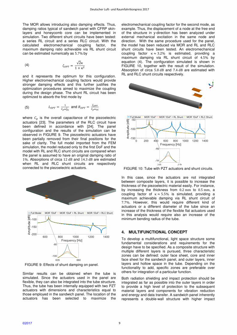
Similar results can be obtained when the tube is simulated. Since the actuators used in the panel are flexible, they can also be integrated into the tube structure. Thus, the tube has been internally equipped with two PZT actuators with dimensions and characteristics equal to those employed in the sandwich panel. The location of the actuators has been selected to maximize the
electromechanical coupling factor for the second mode, as example. Thus, the displacement of a node at the free end of the structure in y-direction has been analyzed under external mechanical excitation in the same node and direction. With the same procedure used for the panel, the model has been reduced via MOR and RL and RLC shunt circuits have been tested. An electromechanical coupling factor κ ≈ 3.2% is estimated, providing a maximum damping via RL shunt circuit of 4.5% by equation (4). The configuration simulated is shown in FIGURE 10, together with the result of the simulation. Absorption of circa 5.8dB and 7.4dB are estimated with RL and RLC shunt circuits respectively.
FIGURE 10: Tube with PZT actuators and shunt circuits.
In this case, since the actuators are not integrated between composite layers, it is possible to increase the thickness of the piezoelectric material easily. For instance, by increasing the thickness from 0.2mm to 0.5mm, a coupling factor of κ ≈ 5.5% is simulated, providing a maximum achievable damping via RL shunt circuit of 7.7%. However, this would require different kind of actuators or a different diameter of the tube since an increase of the thickness of the flexible flat actuators used in this analysis would require also an increase of the minimum bending radius of the tube.
4. MULTIFUNCTIONAL CONCEPT
To develop a multifunctional, light space structure some fundamental considerations and requirements for the design have to be specified. As a composite structure with multiple different layers is pursued, three characteristic zones can be defined: outer face sheet, core and inner face sheet for the sandwich panel, and outer layers, inner layers and hollow space in the tube. Depending on the functionality to add, specific zones are preferable over others for integration of a particular function.
Both radiation shielding and impact protection should be integrated as far as possible into the outer layers in order to provide a high level of protection to the subsequent material layers and components for vibration reduction and energy and data transfer. A sandwich panel inherently represents a double-wall structure with higher impact
600 800 1000 1200 1400
Frequency [Hz]
-200
-150
-100
Full Model MOR 1DoF MOR 1DoF + RL Shunt MOR 1DoF + RLC Shunt
0 200 400 600 800 1000 1200 1400
Frequency [Hz]
-150
-100
-50Full Model MOR 1DoF MOR 1DoF + RL Shunt MOR 1DoF + RLC Shunt
635 660
-100
-80
©2017
Deutscher Luft- und Raumfahrtkongress 2017
9

resistance than a single wall of equal aerial density. Due to their geometry and dimensions, the impact risk for tubes is usually very low compared to extensive panels. Hence, impact protection for tubes is viewed only as optional functionality. With regard to thermal conduction heat can be transferred in-plane and through the thickness of the laminated composite and the thermal conductivities may vary significantly between these two directions. Vibration reduction under bending deformation is most effective when the piezoelectric transducers are placed as far away as possible from the neural axis of the structural element, ideally in the outer layers of the composite. The transmission of electric energy and data is established by some sort of cables or wires which provide no structural function. Therefore energy and data transfer can be combined in a single layer. If integrated in proximity of the neutral axis, this non-structural layer does not reduce the bending stiffness of the composite structure and secondly the components within this layer are minimally strained. High potential for integration of functional layers into a sandwich panel is provided by the core which can be designed as multi-layer core with functional intermediate layers. Concerning the tube, the hollow space can be used to incorporate additional functions. All active and passive functions shall be integrated as part of the load-carrying structure. In satellite design also surface coatings, paints and MLIs play a role but here these types of solutions are considered only as additional means of influencing certain mechanical or physical properties of the satellite surface.
Based on the findings presented in chapters 2 and 3 and the design considerations described above, a concept for a multifunctional sandwich panel has been developed and is being pursued with regard to manufacturing and testing. The concept includes all passive and active functions and a schematic sketch is depicted in FIGURE 11.
FIGURE 11: Concept of multifunctional sandwich panel with integrated passive and active functions.
The sandwich panel is composed of two CFRP face sheets, a double aluminum honeycomb core separated by a multifunctional polymeric intermediate layer with embedded optical fibers for data transmission and flat cables for energy transfer. Pitch-based carbon fibers are used as reinforcing fiber in the face sheets in order to increase the in-plane thermal conductivity of the laminate. CNT-modified cyanate ester is used as matrix material. Cyanate esters have higher radiation resistance than conventional epoxies and carbon nanotubes additionally improve the thermal conductivity, radiation resistance and impact toughness of the resin. In case higher radiation shielding performance is required carbon fibers may be replaced by ultra-high molecular weight polyethylene fibers which as drawback possess lower thermal
conductivity. Even though polyethylene is considered as best material for radiation shielding, it is difficult to use as matrix as thermoset resins require high processing and curing temperatures. The piezoelectric transducers plus cables for vibration reduction are adhesively bonded to the inner side of both stiff face sheets and the core.
Due to the double-wall character of the sandwich panel an impacting particle at hyper velocity will be fragmented by the outer face sheet which acts as bumper. By dividing the honeycomb core into two core layers plus intermediate layer and using a larger cell size, the channeling effect for the expanding debris cloud is reduced which improves impact protection moderately. For significant improvement of impact resistance a Nextel and a Kevlar fabric, in the style of the Stuffed Whipple shield concept, are added to the intermediate layer. While Nextel is responsible for effective projectile breakup, Kevlar provides high energy-absorption properties to slow down the fragmented particles. Optionally, if better impact resistance is desired, the inner or even both honeycomb core layers can be replaced by aluminum foam. A metallic foam core improves protective and thermal performance of a sandwich panel, but at the cost of higher weight.
The finalization of the conceptual design of the multifunctional tube is still in progress. The main structure of the tube is made of CFRP layers as used for the panel, but with most fibers oriented in axial direction to increase the axial and bending stiffness of the tube. The piezoelectric actuators are bent and adhesively bonded onto the inner side of the tube at several locations along the circumference. The cables for data and energy transfer are integrated on the inner side of the tube, too.
In general, also other multifunctional concepts are possible and feasible with regard to choice of materials and layer build-up. The concept described above shows promising potential in terms of multifunctional performance and it is based on mainly well-established materials and technologies. Furthermore, conventional laminate and sandwich manufacturing processes are applicable so that this concept shall be pursued until prototype stage.
5. MANUFACTURING, TESTING AND OUTLOOK
Before manufacturing and testing a multifunctional prototype of a sandwich panel and a tube, coupon tests for each function shall be conducted. By producing a set of different samples the materials and components can be tested separately with regard to each function. In the first step, sandwich coupons are being produced because laminated plate type structures can be manufactured in-house at the Institute of Structural Mechanics and Lightweight Design (SLA). When feasibility of the concept and the compatibility of the manufacturing process and materials are shown, tubes shall be fabricated as well.
For the sandwich coupons optical fibers, flat electric cables and piezoelectric actuators have been purchased as single components as presented in chapter 3. Fibers and cables will be embedded in a separate polymeric layer of constant thickness. The composite face sheets are produced in-house and the aluminum honeycomb and foam core are machined in order to create recesses for the piezoelectric transducers and their cables. The size of the sandwich coupon is 300 mm x 150 mm and the total core thickness is 20 mm. The face sheets have a quasi-
Intermediate layer with embedded optical fiber and flat electric cable
PZT actuator
CFRP facesheet
Honeycomb core Nextel layer
Kevlar layer
©2017
Deutscher Luft- und Raumfahrtkongress 2017
10

isotropic layup with total thickness of 0.6 to 1.0 mm. Even though in the long term a one-step-process for the production of the multifunctional sandwich panel is envisaged, the single layers of the coupon will be prepared and cured separately at the beginning. Afterwards, all layers will be bonded together adhesively to create a sandwich. At the moment issues of handling and low temperature resistance of the optical fibers and electric cables impede the use of an autoclave process as high-quality one-shot production method.
The definition of the test campaign and the preparation of testing equipment for the sandwich coupon are still in progress. Before testing the performance of each of the active and passive functions, the quality of the adhesive bonding and the compatibility between the different materials and components will be examined in-house. When acceptable structural integrity of the sandwich is achieved a tube coupon shall be manufactured, too. The results of the test campaign on coupon-level will provide useful information for the design of the multifunctional prototype which will be produced subsequently.
6. CONCLUSIONS
The concept design of a multifunctional load-carrying satellite structure made of composite materials has been presented in this paper. Two representative structures have been considered: a sandwich panel and a tube. The multifunctional concept integrates both passive functions (heat transfer, radiation shielding and impact protection) and active functions (vibration reduction, energy and data transfer) into the structure. First, suitable materials have been selected for application in a satellite structure. Analytical and numerical methods have been used to analyze different sandwich and tube configurations with respect to the passive and active functions. In particular, numerical simulations have been implemented to verify the feasibility of the integration of piezoelectric actuators in composite structures in order to achieve vibration reduction. After that the multifunctional concept design has been described for the sandwich panel and the tube. A test campaign is prepared to validate the proposed multifunctional concept. Hence, an outlook has been given on the coupon design and the manufacturing process for the coupons with integrated passive and active functions.
7. REFERENCES
[1] W. Ley et al., Ed., Handbook of space technology, München: Carl Hanser Verlag, 2008.
[2] R. Edeson et al., "Conventional stable structure for space optics: the state of the art.," Acta Astronaut, vol. 66, pp. 13-32, 2010.
[3] R. Salloum, "Optimization of shunt damped composite structures using negative capacitances," PhD Dissertation - TU Darmstadt, Germany, 2016.
[4] M. Kutz, Ed., Handbook of Materials Selection, New York: John Wiley & Sons, Inc., 2002.
[5] T. J. Lu et al., "Heat transfer in open-cell metal foams," Acta mater, vol. 46, no. 10, pp. 3619-3635, 1998.
[6] M. H. E. Glowania, Untersuchungen und Methodenentwicklung zur Steigerung der
Wärmeleitfähigkeit von Faserverbundkunststoffen, T. Gries, Ed., Aachen: Shaker Verlag, 2013.
[7] J. W. Wilson et al., "Improved spacecraft materials for radiation protection," 2000.
[8] O. Gohardani et al., "Potential and prospective implementation of carbon nanotubes on next generation aircraft and space vehicles: A review of current and expected applications in aerospace sciences," Progress in Aerospace Sciences, vol. 70, pp. 42-68, 2014.
[9] H. Shulman et al., "Nuclear and space radiation effects on materials," Washington, DC, 1970.
[10] P. B. Willis, Qualification of Spacecraft Materials for Use in Harsh Radiation Environments, Long Beach: Presentation at 11th ASCE Aerospace Division International Conference, 2008.
[11] P. B. Willis, Survey of Radiation Effects on Materials, Monrovia: Presentation at the OPFM Instrument Workshop, 2008.
[12] ECSS Secretariat, "Structural materials handbook - Part 7: Thermal and environmental integrity, manufacturing aspects, in-orbit and health monitoring, soft materials, hybrid materials and nanotechnologies," Noordwijk, 2011.
[13] E. L. Christiansen et al., "Handbook for Designing MMOD Protection," Houston, 2009.
[14] K. Sofocleous et al., "The influence of carbon nanotubes and shape memory alloy wires to controlled impact resistance of polymer composites," Journal of Composite Materials, vol. 51(2), pp. 273-285, 2017.
[15] S. Ryan et al., "Hypervelocity Impact Testing of Aluminum Foam Core Sandwich Panels," Houston, 2015.
[16] ESA, "SPENVIS - The Space Environment Information System," Royal Belgian Institute for Space Aeronomy, [Online]. Available: https://www.spenvis.oma.be/. [Accessed 2017].
[17] S. Ryan et el., "Micrometeoroid and Orbital Debris (MMOD) Shield Ballistic Limit Analysis Program," Houston, 2010.
[18] "https://www.piceramic.de," [Online].
[19] K. Levin, "Durability of embedded fibre optic sensors in composites," PhD Dissertation - Royal Institute of Aeronautics, Stockholm, Sweden, 2001.
[20] "www.adaptrosim.de," [Online].
[21] D. Gieser, "Anwendung und Weiterentwicklung effizienter Methoden zur Simulation von Systemen mit Piezo-Elektrischen Wandlern in Zeitbereich," Masterthesis Hochschule Darmstadt; Fraunhofer Institute LBF, Darmstadt, Germany, 2015.
[22] B. Kranz, "Beitrag zur numerischen Beschreibung des funktionellen Verhaltnes von Piezoverbundmodell," PhD Dissertation TU Chemnitz, Germany, 2011.
[23] B. Götz, "Vergleich von Mechanischen und Elektromechanischen Tilgern unter Berücksichtigung der Eingebrachten Masse," Masterthesis TU Darmstadt, Germany, 2013.
[24] R. Salloum et al., "Optimally tuned resonant negative capacitance for piezoelectric shunt damping based on measured electromechanical impedance," SPIE, San Diego, USA, 2015.
©2017
Deutscher Luft- und Raumfahrtkongress 2017
11