
Multifunctional fiberglass-reinforced PMMA-BaTiO3 ...nanofm.mse.gatech.edu/Papers/Stefanescu EA et...
9
Multifunctional fiberglass-reinforced PMMA-BaTiO 3 structural/dielectric composites Eduard A. Stefanescu, Xiaoli Tan, Zhiqun Lin, Nicola Bowler, Michael R. Kessler * Department of Materials Science and Engineering, Iowa State University, 2220 Hoover Hall, Ames, IA 50011, USA article info Article history: Received 23 November 2010 Received in revised form 23 February 2011 Accepted 28 February 2011 Available online 8 March 2011 Keywords: Dielectric Multifunctional Polymer composite abstract Fiberglass-reinforced polymer composites were investigated for potential use as structural dielectrics in multifunctional capacitors that require simultaneous excellent mechanical properties and good energy storage characteristics. Composites were fabricated employing poly(methyl methacrylate), PMMA, as the structural matrix. While barium titanate (BaTiO 3 ) nanopowder was added to the composites for its high room temperature dielectric constant, fiberglass was employed to confer high stiffness. A conductive polymer blend of poly (3,4-ethylenedioxythiophene) and polystyrene sulfonate (PEDOT:PSS) was used to coat the BaTiO 3 nanoparticles with the purpose of further elevating the dielectric constant of the resultant PMMA-composites. FTIR spectroscopy, TGA and SEM measurements were conducted to prove the successful coating of BaTiO 3 nanoparticles with the PEDOT:PSS blend. TEM measurements revealed a good dispersion of coated nanoparticles throughout the PMMA matrix. The fiberglass-reinforced- PMMA composites containing neat and coated BaTiO 3 were found to exhibit excellent stiffness. In addition, the use of PEDOT:PSS in conjunction with BaTiO 3 was observed to improve the dielectric constant of the composites. Finally, the dielectric constant of the structural composites was found to vary only slightly with temperature. Ó 2011 Elsevier Ltd. All rights reserved. 1. Introduction In recent years substantial efforts have been dedicated to finding new alternatives for performance, weight and volume improve- ments in batteries and capacitors [1e4]. Such efforts are generated in part by the ever-growing demand for energy storage in a wide variety of emerging applications, including hybrid ground vehicles, airplanes and space shuttles. In the most common electronic devices present today on the market the majority of circuit components are passive, accounting for more than 80% of printed wired surface area [1]. In addition, capacitors, especially those with high capacitances, are among the largest passive electronic components. A recent study indicated that in 2008 approximately 90% (by volume) of the capacitor market was dominated by the ceramic capacitors [5]. While commercial ceramic capacitors are typically employed where small sizes along with high capacitances and insulation resistances are required, they are not intended for precision applications due to high variations in the capacitance with temperature [2]. In contrast, polymer film capacitors are predominantly used in applications requiring low dielectric absorption and loss factors over a wide temperature range [2]. However, polymer film capacitors are char- acterized by smaller capacitances due to their lower dielectric constants compared to the ceramic counterparts. We hypothesize that polymer composites obtained through the addition of ceramic powders into polymeric matrixes, can result in improved dielectric candidates for capacitors with an enlarged spectrum of applications. The spectrum of applications can be even further expanded to structural components when such capacitors are designed with structural characteristics, such as high-strength and stiffness. Fiberglass-reinforced polymer composites have been exten- sively studied in past decades, primarily for their high specific strength and stiffness [6,7]. Such fiberglass-reinforced materials are typically employed in applications where fatigue durability and high fracture toughness are important requirements [6]. Several reports have previously focused on the fabrication and analysis of poly(methyl methacrylate), PMMA-based materials containing fiberglass as reinforcement [8,9]. PMMA is a high-strength, amor- phous polymer possessing good dimensional stability and outdoor wearing properties. Owing to these characteristics, PMMA is among the most heavily studied polymers for nano- and micro-composite fabrications [10e19]. Various in situ [10,12,13,15,16] and/or ex-situ [14e16,19] approaches have been used to disperse different fillers in PMMA matrixes. Because of its high optical transparency PMMA is commonly employed in various applications as a low-density and * Corresponding author. Tel.: þ1 515 294 3101. E-mail address: [email protected] (M.R. Kessler). Contents lists available at ScienceDirect Polymer journal homepage: www.elsevier.com/locate/polymer 0032-3861/$ e see front matter Ó 2011 Elsevier Ltd. All rights reserved. doi:10.1016/j.polymer.2011.02.050 Polymer 52 (2011) 2016e2024
Transcript of Multifunctional fiberglass-reinforced PMMA-BaTiO3 ...nanofm.mse.gatech.edu/Papers/Stefanescu EA et...

lable at ScienceDirect
Polymer 52 (2011) 2016e2024
Contents lists avai
Polymer
journal homepage: www.elsevier .com/locate/polymer
Multifunctional fiberglass-reinforced PMMA-BaTiO3 structural/dielectriccomposites
Eduard A. Stefanescu, Xiaoli Tan, Zhiqun Lin, Nicola Bowler, Michael R. Kessler*
Department of Materials Science and Engineering, Iowa State University, 2220 Hoover Hall, Ames, IA 50011, USA
a r t i c l e i n f o
Article history:Received 23 November 2010Received in revised form23 February 2011Accepted 28 February 2011Available online 8 March 2011
Keywords:DielectricMultifunctionalPolymer composite
* Corresponding author. Tel.: þ1 515 294 3101.E-mail address: [email protected] (M.R. Kessle
0032-3861/$ e see front matter � 2011 Elsevier Ltd.doi:10.1016/j.polymer.2011.02.050
a b s t r a c t
Fiberglass-reinforced polymer composites were investigated for potential use as structural dielectrics inmultifunctional capacitors that require simultaneous excellent mechanical properties and good energystorage characteristics. Composites were fabricated employing poly(methyl methacrylate), PMMA, as thestructural matrix. While barium titanate (BaTiO3) nanopowder was added to the composites for its highroom temperature dielectric constant, fiberglass was employed to confer high stiffness. A conductivepolymer blend of poly (3,4-ethylenedioxythiophene) and polystyrene sulfonate (PEDOT:PSS) was used tocoat the BaTiO3 nanoparticles with the purpose of further elevating the dielectric constant of theresultant PMMA-composites. FTIR spectroscopy, TGA and SEM measurements were conducted to provethe successful coating of BaTiO3 nanoparticles with the PEDOT:PSS blend. TEM measurements revealeda good dispersion of coated nanoparticles throughout the PMMA matrix. The fiberglass-reinforced-PMMA composites containing neat and coated BaTiO3 were found to exhibit excellent stiffness. Inaddition, the use of PEDOT:PSS in conjunction with BaTiO3 was observed to improve the dielectricconstant of the composites. Finally, the dielectric constant of the structural composites was found to varyonly slightly with temperature.
� 2011 Elsevier Ltd. All rights reserved.
1. Introduction
In recent years substantial efforts have been dedicated to findingnew alternatives for performance, weight and volume improve-ments in batteries and capacitors [1e4]. Such efforts are generated inpart by the ever-growing demand for energy storage in a widevariety of emerging applications, including hybrid ground vehicles,airplanes and space shuttles. In the most common electronic devicespresent today on the market the majority of circuit components arepassive, accounting for more than 80% of printed wired surface area[1]. In addition, capacitors, especially those with high capacitances,are among the largest passive electronic components. A recent studyindicated that in 2008 approximately 90% (by volume) of thecapacitor market was dominated by the ceramic capacitors [5].While commercial ceramic capacitors are typically employed wheresmall sizes along with high capacitances and insulation resistancesare required, they are not intended for precision applications due tohigh variations in the capacitance with temperature [2]. In contrast,polymer film capacitors are predominantly used in applicationsrequiring low dielectric absorption and loss factors over a wide
r).
All rights reserved.
temperature range [2]. However, polymer film capacitors are char-acterized by smaller capacitances due to their lower dielectricconstants compared to the ceramic counterparts. We hypothesizethat polymer composites obtained through the addition of ceramicpowders into polymeric matrixes, can result in improved dielectriccandidates for capacitors with an enlarged spectrum of applications.The spectrum of applications can be even further expanded tostructural components when such capacitors are designed withstructural characteristics, such as high-strength and stiffness.
Fiberglass-reinforced polymer composites have been exten-sively studied in past decades, primarily for their high specificstrength and stiffness [6,7]. Such fiberglass-reinforcedmaterials aretypically employed in applications where fatigue durability andhigh fracture toughness are important requirements [6]. Severalreports have previously focused on the fabrication and analysis ofpoly(methyl methacrylate), PMMA-based materials containingfiberglass as reinforcement [8,9]. PMMA is a high-strength, amor-phous polymer possessing good dimensional stability and outdoorwearing properties. Owing to these characteristics, PMMA is amongthe most heavily studied polymers for nano- and micro-compositefabrications [10e19]. Various in situ [10,12,13,15,16] and/or ex-situ[14e16,19] approaches have been used to disperse different fillersin PMMA matrixes. Because of its high optical transparency PMMAis commonly employed in various applications as a low-density and

E.A. Stefanescu et al. / Polymer 52 (2011) 2016e2024 2017
shatter-resistant alternative to glass. Additionally, the high stiffnessof PMMA, along with its biocompatibility, renders it the matrix ofchoice in cements for bone-substitute applications [20,21]. Despiteits exceptional mechanical behavior, PMMA exhibits a rather lowdielectric constant, with values between 3 and 8, depending onmolecular weight and testing frequency [15,18,22].
Barium titanate, BaTiO3, is a ceramic material with a perovskitecrystal structure characterized by excellent ferroelectric andpiezoelectric properties [5,14,23e25]. The ferroelectricity of thisceramic causes very high dielectric constants (e0), with the highestreported e0 value reaching 10,000 [5]. Due to its very high e0, BaTiO3has been extensively employed in the fabrication of multilayerceramic capacitors [24]. In recent years BaTiO3 has been utilized forcomposite preparation in conjunction with various polymers,including PMMA [14,23,24,26]. It has been suggested that thesurface functionalization of BaTiO3 with various chemicals cansignificantly improve the interactions between BaTiO3 and thepolymer matrix [14,26].
Poly (3,4-ethylenedioxythiophene) (PEDOT) has been a heavilystudied conductive polymer during the past decade [27e32]. Theintense interest in PEDOT-containing materials arises mainly fromthe remarkable electron-conducting properties of this polymer,coupled with its high chemical stability, low-density and relativelylow cost [27,32]. PEDOT is often employed in conjunction withsulfonated polymers such as polystyrene sulfonate (PSS). The roleof PSS in PEDOT:PSS mixtures is two-fold: on one hand, PSSprovides the charge-balancing counter ions necessary for thestabilization of the p-doped PEDOT; on the other hand, PSSpromotes the homogeneous dispersion of PEDOT chains in water,allowing for the production and commercialization of PEDOT:PSSaqueous solutions [31]. When utilized from aqueous solutions,PEDOT has an excellent film-forming ability, which allows forcoating various powdery and/or non-powdery materials; thesematerials include carbon nanotubes (CNT) [27], barium ferrite(BaFe) [32], and cellulose acetate [28].
Herein, we focused on PMMA-fiberglass structural dielectricscontaining neat or PEDOT:PSS-coated BaTiO3 particles, for potentialuse in multifunctional capacitors that require superior stiffness andenergy storage characteristics. Themultifunctional capacitors couldbe potentially employed as substitutes for static load-carryingcomponents in traditional structures (e.g., hybrid vehicles orairplanes) with the purpose of reducing the overall system weightand/or volume.
2. Experimental
2.1. Materials
All chemicals were used as received from their vendors, withoutany additional purification. PMMA (MW ¼ 996,000 g/mol, inherentviscosity ¼ 1.25 dL/g) and PEDOT:PSS (1.3 wt% dispersion in H2O)were purchased from SigmaeAldrich Corporation (St. Louis, MO).BaTiO3 nanoparticles (NanOxide�, HPB 1000, <100 nm, lot #
Table 1Sample composition and dielectric breakdown strengths.
Sample name Composition (grams)
Fiberglass PMMA Nea
FG-PMMA 4 3 N/AFG-PMMA-BT 4 3 3FG-PMMA-BT(PEDOT:PSS) 4 3 N/A
a BaTiO3 coated with PEDOT:PSS.b Breakdown strength values were calculated as the mean of five measured values.
BTA040120MC) were obtained from TPL Inc (Albuquerque, NM).The fiberglass fabric (bi-directional E-Glass, thickness 0.008”) wasobtained from Fiber Glast Developments Corporation (Brookville,OH). Chloroform (HPLC grade, d ¼ 1.49 g/mL) was purchased fromFisher Scientific (Hampton, NH).
2.2. Coating of BaTiO3 particles
BaTiO3 nanoparticles (13 g) were added to a flask containing10 mL PEDOT:PSS aqueous solution (dark blue color). The ceramicparticles were vigorously dispersed via probe sonication fora period of 5 min. Following sonication, the flask containing theaqueous dispersion was placed on a hot plate at 80 �C, and theentire systemwas gently stirred overnight with a magnetic stir bar.After the entire amount of water was evaporated, the BaTiO3particles (white in the neat form) exhibited a blue color, indicatingan effective coating. The coated particles were additionally dried inan oven at 80 �C overnight and stored in a tightly capped vial. Thecalculated amount of PEDOT:PSS in the resultant coated BaTiO3
particles was z1 wt.%.
2.3. PMMA-based composites fabrication
The PMMA powder was initially dissolved in chloroform ina mass ratio PMMA:CHCl3 of 1:9. Following dissolution either neator coated BaTiO3 particles were added to the polymer solution andhomogeneously dispersed employing a probe sonicator. Each of theresultant dispersions was manually spread with a spatula on eachof the two sides of a fiberglass patch, previously cut to desireddimensions (see schematic in Fig. 4). In between individual spreadsthe solvent was evaporated on a hot plate at 50 �C. Subsequently,the resultant polymer composites were compression-molded ina hot press at 200 �C at pressures>200 PSI (>14 atm). The pressurewas removed only after the press-plates were cooled back to roomtemperature. Following this method three distinct polymercomposites were fabricated (Fig. 4) with the compositionsdescribed in Table 1.
2.4. Characterization of nanocomposites
Dielectric properties of the samples were characterized usinga Novocontrol dielectric spectrometer (Novocontrol TechnologiesGmBh, Hundsangen, Germany). Frequency sweeps were performedfrom 1 Hz to 1 MHz. The dielectric constant and tan d values wererecorded with the WinDeta software. Thermogravimetric analysis(TGA) was performed with a TA Instruments (New Castle, DE) Q50thermobalance. Neat and coated BaTiO3 powders were subjected toTGA measurements in air at a heating rate of 10 �C/min, whereaspolymer composite samples were analyzed in air with a heatingrate of 20 �C/min. Differential scanning calorimetry (DSC)measurements were conducted using a TA Instruments Q20analyzer at a heating rate of 10 �C/min. Dynamic mechanicalanalysis (DMA) was conducted on a TA Instruments Q800 analyzer
Dielectric breakdown strengthb
(kV/cm)t BaTiO3 Coated BaTiO3
a
N/A 158 (�14%)N/A 139 (�20%)3 76 (�17%)

E.A. Stefanescu et al. / Polymer 52 (2011) 2016e20242018
at a heating rate of 3 �C/min. Tension tests were performed witha Universal Testing Machine (Instron 5569) on ASTM type Vsamples at a crosshead speed of 1 mm/min. Dielectric breakdownmeasurements were performed on an Instron/CEAST (Norwood,MA) dielectric rigidity apparatus at a frequency of 50e60 Hz,a voltage ramp rate of 0.1 kV/s and a current intensity of 10 mA.Scanning electron microscopy (SEM) was carried out using a FEIQuanta 250 field emissionmicroscope operated under high vacuumin the secondary-electrons mode. Sample preparation for SEMincluded sputter coating the samples with a thin layer of gold.Transmission electron microscopy (TEM) was performed usinga JEOL 2100 200 kV microscope. The samples were prepared forTEM imaging by ultramicrotomy. Multiple discrete sections wereexamined by both SEM and TEM and only representative imagesare presented here. Duplicate measurements showed excellentreproducibility of all measured parameters.
3. Results and discussion
3.1. Coating of BaTiO3 particles
The coating of BaTiO3 particles was performed, on one hand, toimprove the interaction between the inorganic particles with theorganic polymer matrix and, on the other hand, to directly impactthe dielectric properties of the resultant polymer composites. Toverify the effectiveness of the coating process, a series of FTIR, TGAand SEM measurements were performed on both the non-coatedand the coated BaTiO3 particles. Fig. 1 shows the FTIR spectra fromthe PEDOT:PSS, neat BaTiO3 and coated BaTiO3 samples at roomtemperature. In the PEDOT:PSS curve a multitude of peaks is visiblebetween 950 and 1750 cm�1. The small peak at 976 is attributed tothe CeS bond vibrations in the thiophene rings of PEDOT [27]. Thepeak at 1085 cm�1 is assigned to the stretchingmodes of the CeOeCbonds in PEDOT, but the broad shoulder observed to the right of thepeak is expected to contain the component from the bending of theCeH bond in the aromatic rings of PSS (bond previously observed at1007 cm�1 for PSS alone) [27]. Additionally, the broad peak at1190 cm�1 is representative for the symmetric vibrations of theeSO3 group in PSS. The broad short peak at 1324 cm�1 (not indi-cated with an arrow) and the multitude of peaks visible around1540 cm�1can be attributed to the CeC and C]C stretching ofqunoidal structure and stretching of thiophene rings in PEDOT,respectively [32]. The larger peak at 1637 cm�1may be attributed toskeletal vibrations involving stretching of the less strained C]Cbonds from the aromatic rings of PSS. On the other hand, for theneat BaTiO3, the two wide bands at 428 cm�1and 565 cm�1 are
Fig. 1. FT IR spectra from the PEDOT:PSS, neat BaTiO3 and PEDOT:PSS-coated BaTiO3
samples at room temperature.
characteristic to this type of ceramic and have been previouslyreported [23e25]. Furthermore, the small peak at 860 cm�1corres-ponds to the TieO stretching modes [23], and the peaks at1440 cm�1and 1630 cm�1 are attributed to the symmetric andasymmetric stretching vibrations of carboxylic groups [25]. Finally,the FTIR curve corresponding to the PEDOT:PSS-coated BaTiO3sample is observed to exhibit contributions from both the neatBaTiO3 and the neat PEDOT:PSS, indicating a successful depositionof the polymeric blend at the surface of the ceramic nanoparticles.A schematic showing the possible physical interactions between thepolymeric chains and BaTiO3 particles is shown in the “supportinginformation”.
TGA measurements were performed primarily to determine theactual amount of PEDOT:PSS polymer deposited at the surface ofBaTiO3 particles. Fig. 2 shows the TGA curves obtained from thecoated and neat BaTiO3 particles. The inset in Fig. 2 displays thephysical appearance of the inorganic particles prior to, and after thecoating. Although the profile of the two TGA curves is not signifi-cantly different, in the case of the curve corresponding to thePEDOT:PSS-coated BaTiO3 particles a more pronounced drop can beobserved for the temperature range between 300 and 500 �C. It isapparent that upon heating in air from room temperature to 800 �Cthe neat BaTiO3 particles lose 1.5% of their initial weight. On theother hand, the PEDOT:PSS-coated BaTiO3 particles lose 2.4% oftheir initial weight on being subjected to an identical decomposi-tion program. The difference in the lost mass percentage (0.9%)between the two samples is attributable to the presence of thepolymeric blend coating at the surface of the ceramic particles. Thispractical value of 0.9 wt.% PEDOT:PSS is in a good agreement withthe calculated value of 1 wt.%. Duplicate measurements showedexcellent reproducibility of these results. Regarding the physicalappearance of the BaTiO3 particles, it is evident that prior to coatingthe neat inorganic powder is bright white (left image in the inset).Following the PEDOT:PSS deposition process the BaTiO3 particlesexhibit a light-blue color (right image in the inset), which resem-bles the color of PEDOT:PSS, indicating successful coating ofPEDOT:PSS on the surface of BaTiO3 particles.
SEM measurements were carried out on the neat and coatedpowders to uncover morphological differences between the twosystems at the nanometer and micrometer scales. Fig. 3 shows theSEM micrographs at two magnifications for the neat BaTiO3 (a andb) and (PEDOT:PSS)-coated BaTiO3 (c and d). The lowmagnificationimage for neat BaTiO3 (a) reveals that in the powdery form theinorganic nanoparticles coalesce together and form approximatelyspherical aggregates with diameters ranging from submicron toabout 20 mm. The high magnification image for neat BaTiO3 (b)
Fig. 2. TGA traces from BaTiO3 and (PEDOT:PSS)-coated BaTiO3 heated in air. Theheating rate was 10 �C/min.

Fig. 3. SEM images at two distinct magnifications for the neat BaTiO3 (a and b) and (PEDOT:PSS)-coated BaTiO3 (c and d).
E.A. Stefanescu et al. / Polymer 52 (2011) 2016e2024 2019
shows that the ceramic nanoparticles, making up the sphericalaggregates, are in direct contact with each other. On the other hand,for the (PEDOT:PSS)-coated BaTiO3 system, the low magnificationimage (c) reveals that the micrometric aggregates have randomshapes with dimensions up to 25 mm. Furthermore, in the highmagnification image for the coated powder (d) the nanostructuresappear to be interconnected and covered in the polymer blanket,indicating a successful coating even at the nanoscale. Multiplepowder-covered areas were examined by SEM and only represen-tative images are presented here for the two systems. These weakagglomerations shown in Fig. 3 are introduced during the dryingstep in the manufacturing process and are easily broken up byultrasonication as will be shown later.
3.2. PMMA-composites: fabrication and morphology
Subsequently, the three polymer composites described inTable 1 were prepared employing a solution-spreading methodfollowed by compression-molding, as described in Section 2. Theschematic diagram in Fig. 4 illustrates the method employed forcomposite fabrication. Photographs of the three fiberglass-PMMAcomposites are also shown at the bottom of Fig. 4. In this processthe polymeric dispersion containing the ceramic particles is shear-spread with a spatula, resulting in uniform coating of the fiberglassfabric. The final compression-molding step leads to the formationof a compact, solvent-free composite material with excellentthermo-mechanical properties.
A series of TEM measurements were carried out on the polymercomposite comprising the coated BaTiO3 to determine whether thenanoparticles are distributed uniformly throughout the PMMA
matrix. Fig. 5 shows the TEM micrographs at different magnifica-tions for the FG-PMMA-BT(PEDOT:PSS) sample (see Table 1). Thesample preparation prior to TEM measurements included ultra-microtoming a very thin PMMA-ceramic section sitting on top ofthe fiberglass threads, at the outer surface. The BaTiO3 nano-particles are clearly visible in both micrographs, where the graybackground represents the PMMA matrix. Although the SEMmicrograph for the coated BaTiO3 particles (Fig. 3c and d) indicatedan agglomeration of the nanostructures in the powdery form, thelow magnification TEM image (Fig. 5a) indicates an excellentdistribution of the coated BaTiO3 nanoparticles in the PMMAmatrix. From the high magnification image (Fig. 5b) it is apparentthat the nanoparticles range in size from about 80 nm to 100 nm.
3.3. Thermo-mechanical analysis of PMMA-composites
Fig. 6 shows the TGA (a) and derivative TGA (DTGA, (b)) data asa function of temperature for the three composite samples. Forcomparison, TGA and DTGA results from a reference, neat PMMAsample are also shown. From the TGA results it is apparent thataddition of either neat or coated BaTiO3 nanoparticles to thecomposites increases the decomposition temperature of PMMA.However, it is not very clear from the TGA plot (Fig. 6a) how thefiberglass alone impacts the decomposition temperature of PMMA.This feature is readily observable in the DTGA plot (Fig. 6b); it canbe seen that the PMMA decomposition occurs at a higher temper-ature in the presence of fiberglass (maximum at 342 �C) comparedto when PMMA is analyzed in the neat form (maximum at 300 �C).All decomposition peaks in the DTGA plot are accompanied bybroad shoulders. The BaTiO3 filler and/or fiberglass residue values

Fig. 4. The schematic (upper panel) shows the fabrication of PMMA-based composites containing fiberglass and particulate filler BaTiO3. The components are: 1 e fiberglass mesh, 2e vial containing the PMMA-filler dispersion in chloroform, 3 e PMMA-filler dispersion in chloroform, 4 e final PMMA-based composite containing fiberglass and particulate fillerBaTiO3. The lower panel presents pictures of the three composite films described in Table 1.
E.A. Stefanescu et al. / Polymer 52 (2011) 2016e20242020
(%) from the combustion of the polymeric samples are in a goodagreement with the filler amounts weighed during sample prepa-ration (Fig. 6a).
Fig. 7a and b shows the storage modulus (E0) and loss tangent(tan d) of the PMMA-composites, as a function of temperature,respectively. The DMA curves were obtained from rectangular-shaped samples subjected to a heating cycle with a rate of 3 �C/minat a frequency of 1 Hz. It is clear that the composite samples con-taining either neat or coated BaTiO3 nanoparticles exhibit highE0 values. However, even in the absence of BaTiO3 (i.e., FG-PMMAsample) the storage modulus is quite high, exhibiting a roomtemperature value of around 4 GPa. As expected, all polymericsamples experience a decrease of the storage modulus at elevatedtemperatures, but the decrease is not very drastic. For example, theFG-PMMA sample exhibits a storage modulus of around 2 GPa at130 �C. The most important features obtained from the tan d curvesare the glass-transition temperatures (Tg) of the polymeric systems,
Fig. 5. TEM images at two distinct magnifications for th
taken as the temperature where the tan d value is maximum(Fig. 7b). The Tg is observed to increase with addition of the BaTiO3nanoparticles to the composites. This trend is highly reproducible.Of course, another possibility would be to consider the Tg as theonset value where the storage modulus, E0, starts the suddendecrease. While the “tan d method” indicates the point where allthe polymer chains have reached the Tg, the “E0-onset method”indicates the point where the shorter polymeric chains havereached the Tg.
Improvement in the resistance to degradation of polymers withaddition of fillers and/or fibers is typically attributed to the barriereffect that the fillers/fibers provide, as they slow down the vola-tilization processes of low-molecular weight products from thepolymer degradation [33]. Consequently, it was not surprising thatthe temperatures corresponding to the main degradation peaks inthe DTGA plot (Fig. 6b) increased with addition of fiberglass andBaTiO3 nanoparticles. The three steps that are typically observed
e FG-PMMA-BT(PEDOT:PSS) sample (see Table 1).

Fig. 6. TGA (a) and derivative TGA (b) data as a function of temperature for the neatPMMA and for the three composite samples. The heating rate was 20 �C/min in allmeasurements.
Fig. 7. Storage modulus (a) and tan d (b) results as a function of temperature for thethree PMMA-based composite samples, obtained from DMA measurements. Theheating rate was 3 �C/min.
E.A. Stefanescu et al. / Polymer 52 (2011) 2016e2024 2021
when neat PMMA is degraded in N2 atmosphere, which have beenpreviously attributed to head-to-head linkages, end-chain satura-tions and random chain scission [17], cannot be easily detected inthe TGA trace obtained from the PMMA degradation in air (Fig. 6a).The presence of broad shoulders around the decomposition peaksin the DTGA plot, however, suggests that the three distinctprocesses observed in N2 atmosphere are also present when thedecomposition is conducted in air, where they might occur fasterand be partially concomitant.
The increase in the stiffness and Tg of PMMA-composites withaddition of fibers and/or various ceramic fillers has been observedand heavily reported in the literature [20,21,34]. The increase in theTg with addition of fillers and/or fibers is primarily attributed toa decrease in mobility of the polymer chains owing to theconfinement of macromolecules to the surface of the fillers and/orfibers. Furthermore, the stiffness increase can be primarily attrib-uted to the stiffness of the filler and/or fiber, which are both severalorders of magnitude higher than that of the pure polymer [35,36].We have recently shown that, in the absence of the fiberglass fabric,CaCu3Ti4O12-loaded PMMA-composites never exceed a storagemodulus value of 2 GPa at room temperature [33]. Comparing thatwith the storagemodulus of the FG-PMMA sample, observed in thiswork (Fig. 7a), it can be concluded that the fiberglass fabric bringsa much higher contribution than the ceramic filler to the overallincrease in stiffness. At a first glance this observation might appearcounterintuitive, since the two BaTiO3-containing samples, FG-PMMA-BT and FG-PMMA-BT(PEDOT:PSS) exhibit much higherstiffness than the BaTiO3-free sample, i.e., FG-PMMA. However, inthe absence of the fiberglass fabric, those samples would exhibitstorage modulus values below 2 GPa, at room temperature.
While the BaTiO3 reinforced samples exhibited significantlyhigher stiffnesses than the FG-PMMA samples, they exhibitedtensile strengths which were statistically similar. The average
tensile strength (of 4 independent samples) for the FG-PMMAwas 208 � 26.8 MPa, while the average tensile strength for theFG-PMMA-BT(PEDOT:PSS) sample was 222.8 � 12.7 MPa, indi-cating that the strength of the composite samples is predominatelydictated by the glass fiber, and is not significantly influenced by thepresence of the BaTiO3 nanoparticles.
3.4. Dielectric analysis of PMMA-composites
The dielectric constant, e0, and dissipation factor, tan d (tand ¼ e00/e0), measured at room temperature (25 �C) for the polymercomposites studied here are displayed in Fig. 8a and b, respectively.The electric field was applied perpendicular to the plane of thefiberglass mesh. The dielectric constant of the FG-PMMA sample(e0 z 6e7) varied only slightly with frequency, barely decreasing asthe frequency was elevated by six orders of magnitude. Addition ofneat BaTiO3 increased the dielectric constant of the material toaround 14, without changing significantly the frequency depen-dence trend. At the same time, the dissipation factor trend of theFG-PMMA-BT remained roughly the same as that of the FG-PMMA,except for frequencies below 10 Hz. Furthermore, the addition ofPEDOT:PSS-coated BaTiO3 was observed to further increase e0
values relative to those of FG-PMMA-BT, and significantly changethe frequency dependence of e0. For example, when compared tothe e0 of FG-PMMA-BT at 1 MHz, the e0 of the FG-PMMA-BT(PEDOT:PSS) composite increases by1.5, but in contrast, at 1 Hz e0
increases by about 6. It should be noted that at 1 Hz the e0 ofFG-PMMA-BT(PEDOT:PSS) is 3 times larger than e0 of FG-PMMA. Inaddition, the tan d values increase when PEDOT:PSS-coated BaTiO3is present in the composites. Importantly, tan d of the FG-PMMA-BT(PEDOT:PSS) sample stayed below 0.07 for the entire range offrequencies studied.

Fig. 8. Dielectric constant (a) and dissipation factor (b) data as a function of frequencyfor the three PMMA-composite samples.
E.A. Stefanescu et al. / Polymer 52 (2011) 2016e20242022
In addition, Table 1 shows the breakdown voltage values for thethree polymer composites. Each value was obtained by calculatingthe mean of five individual measurements conducted on eachcomposite. The breakdown voltage values have been normalized fora thickness of 1 cm to allow comparison of results. It can be obse-rved that the breakdown voltage values decrease in the orderFG-PMMA> FG-PMMA-BT> FG-PMMA-BT(PEDOT:PSS). Moreover,the average size of the breakdown area in the tested samples wasobserved to decrease with addition of the neat and coated BaTiO3filler (see Supporting Information). Although the addition of neatBaTiO3 is observed to lower thebreakdownvoltageof the composite,the decrease is not at all significant (Table 1). Thisminor reduction ofthe breakdown voltage may be attributed to a small increase in thedensity of defects in the volume of the polymer composite withaddition of the neat nanoparticulate powder. On the other hand, theaddition of PEDOT:PSS-coated BaTiO3 is observed to significantlylower the breakdown strength voltage. In the case of the FG-PMMA-BT(PEDOT:PSS) sample the dominant factor responsible for the
Fig. 9. Polarization vs. electric field hysteresis loops for the two PMMA-composites.
decrease of the breakdown voltage is the presence of free ions fromPEDOT:PSS at the surface of nanoparticles, which imparts someelectronic conductivity to the sample.
In order to elucidate the differences in the dielectric behaviorbetween the FG-PMMA-BT and FG-PMMA-BT(PEDOT:PSS) samples,a set of polarization measurements on the two composites wereperformed. Fig. 9 shows the polarization hysteresis loops asa function of electric field for the FG-PMMA-BT and FG-PMMA-BT(PEDOT:PSS) samples. The FG-PMMA-BT(PEDOT:PSS) compositedisplayed a relatively large leakage current under strong electricfields (�60 kV/cm) as demonstrated by the elliptical shaped loop.The curve for the FG-PMMA-BT composite appears in a much morelinear fashionwithminimum hysteretic behavior. In addition, it canbe seen that this FG-PMMA-BT sample was able to withstandstronger electric fields (�100 kV/cm). The results suggest thatwhen the BaTiO3 particles are coated with the conductivePEDOT:PSS blend, upon the incorporation in PMMA-composites thedielectric constant is enhanced at the expense of increased leakagecurrent. The polarization vs. electric field results presented in Fig. 9are in good accordance with the tan d and dielectric breakdownvoltage results shown in Fig. 8b and Table 1, where the dissipationfactor of composites is observed to increase, and the breakdownvoltage to decrease, due to the presence of PEDOT:PSS-coatedBaTiO3 particles.
Fig. 10 shows the temperature-dependent e0 and tan d traces forFG-PMMA (a and b), FG-PMMA-BT (c and d), and FG-PMMA-BT(PEDOT:PSS) (e and f), respectively, as a function of frequency. Thetemperature in all measurements was elevated from �50 �Cto þ100 �C in 25 �C increments. For all three polymeric composites,higher temperatures resulted in elevated e0 and tan d values. In thecase of the FG-PMMA sample, e0 and tan d vary only slightly withtemperature. For example, at 1 MHz e0 increases by less than 0.3 asthe temperature increases from �50 �C to þ100 �C, and at 1 Hz theincrease in e0 is approximately 1 over the same temperature range.For the FG-PMMA-BT sample, a slightly stronger frequency depen-dence of e0 is observed at elevated temperatures, and particularly atlow frequencies. More precisely, at 1 MHz, e0 increases by less than0.7 as the temperature is elevated from�50 �C toþ100 �C, whereasat 1 Hz e0 increases by approximately 2.5. Additionally, for theFG-PMMA and FG-PMMA-BTcomposites tan d values remain below0.04 (<4%) for the entire range of frequencies at all temperaturesstudied. On the other hand, for the FG-PMMA-BT(PEDOT:PSS)composite, an even stronger frequency dependence of e0 over thetemperature range from �50 �C to þ100 �C is observed. For thissample at 1 MHz, e0 increases by nearly 1.3 as the temperature iselevated from �50 �C to þ100 �C, whereas at 1 Hz e0 increases byabout 5. Moreover, tan d values of the FG-PMMA-BT(PEDOT:PSS)composite stay below 0.08 (<8%) over the entire range of frequen-cies at all tested temperatures.
It has been previously suggested that the increase of e0 withaddition of ferroelectric ceramic powders, e.g., BaTiO3, is primarilycaused by the dipolar polarization effect induced by the permanentdipoles existent in the filler [33]. In the case of BaTiO3, thepermanent dipoles result from the uneven distribution of thecharge-density between O, Ba and Ti atoms. For the FG-PMMA-BT(PEDOT:PSS) composite, the presence of PEDOT:PSS coating at thesurface of BaTiO3 particles introduces not only additional dipoles,but also ions, e.g., eSO3
�. For this reason, in the FG-PMMA-BT(PEDOT:PSS) sample the dipolar polarization is complemented byionic polarization [37,38], and the e0 values are, therefore, largerthan those of the composite containing equal amounts of neatBaTiO3 (Figs. 8a and 10c,e). In addition, owing in part to thiscomplementary ionic polarization, in Fig. 9 the P values for theFG-PMMA-BT(PEDOT:PSS) sample appear larger than those of theFG-PMMA-BT sample at any given electrical field (E) in the range
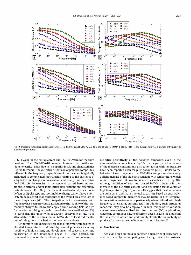
Fig. 10. Dielectric constant and dissipation factor for FG-PMMA (a and b), FG-PMMA-BT (c and d), and FG-PMMA-BT(PEDOT:PSS) (e and f), respectively, as a function of frequency atdifferent temperatures.
E.A. Stefanescu et al. / Polymer 52 (2011) 2016e2024 2023
0e60 kV/cm for the first quadrant and �60e0 kV/cm for the thirdquadrant. The FG-PMMA-BT sample, however, can withstandhigher electrical fields due to its superior insulating characteristics(Fig. 9). In general, the dielectric dispersion of polymer composites,reflected in the frequency dependence of the e0 values, is typicallyattributed to complicated mechanisms relating to the existence ofa lag between changes in polarization and changes in the electricfield [39]. At frequencies in the range discussed here, inducedatomic, electronic and/or ionic lattice polarizations are essentiallyinstantaneous [18]. Only permanent molecular dipoles, ionicdefects of dipolar type and low-mobility charge carriers have a non-instantaneous effect that contribute to the overall dielectric loss atthese frequencies [40]. The dissipation factor decreasing withfrequency has been previously attributed to the inability of the low-mobility charges to follow the applied time-varying field at highfrequencies, resulting in a reduction of electronic oscillations [33].In particular, the underlying relaxation observable in Fig. 10 isattributable to the b-relaxation in PMMA, due to localized oscilla-tion of side groups attached to the polymer backbone.
Furthermore, the dielectric response of polymer composites atelevated temperatures is affected by several processes includingmobility of ionic carriers, and development of space charges andpolarization in the amorphous phase [41]. Upon heating, thecombined action of those effects gives rise to an increase of
dielectric permittivity of the polymer composite, even in theabsence of the ceramic fillers (Fig. 10a). In the past, small variationsof the dielectric constant and dissipation factor with temperaturehave been reported even for pure polymers [2,42]. Similar to thebehavior of neat polymers, the FG-PMMA composite shows onlya slight increase of the dielectric constant with temperature, whichis most significant at low frequencies, as indicated in Fig. 10a.Although addition of neat and coated BaTiO3 trigger a furtherincrease of the dielectric constant and dissipation factor values athigh temperatures (Fig.10), our results suggest that these variationsare quite small and that structural capacitors based on such poly-mer-based composite dielectrics may be useful in high-tempera-ture-variation environments, particularly when utilized with highfrequency alternating currents (AC). In addition, such structuralcapacitors may also be employed in high-temperature-variationenvironments when utilized for direct current (DC) applications,where the continuous nature of current doesn’t cause the dipoles inthe dielectric to vibrate and undesirably elevate the ion mobility orproduce friction-induced effects such as local heating [2].
4. Conclusions
Achieving high stiffness in polymeric dielectrics of capacitors isoften restricted by the competing need for high dielectric constants.

E.A. Stefanescu et al. / Polymer 52 (2011) 2016e20242024
While highdielectric constant thermoplastic polymers, for example,poly(vinylidene fluoride) (PVDF) are too soft and flexible for struc-tural applications, stiff thermoplastic matrixes, such as PMMA, havelow dielectric constants. To achieve multifunctional structuralcapacitors requires the implementation of polymer-basedcomposite dielectrics that exhibit superior mechanical propertiesand high dielectric constants. In this work we showed that PMMA-fiberglass structural dielectrics containing neat and PEDOT:PSS-coated BaTiO3 are valuable potential dielectric candidates formultifunctional capacitor applications. Owing primarily to thepresence of the fiberglass mesh, the ceramic-containing systemsdescribed here exhibit high storage modulus values, in excess of15 GPa, for an extended range of temperatures (30e130 �C). More-over, these composites exhibit good dielectric constants for a widerange of frequencies (1 Hze1 MHz). Addition of PEDOT:PSS-coatedBaTiO3 particleswas found to elevate the dielectric constant relativeto that of the composites containing similar amounts of neat BaTiO3.The high stiffness and dielectric constant values of the compositescould be attributed in part to the excellent dispersion of the ceramicparticles throughout the polymeric matrix, as evidenced by TEM.The presence of the ceramic filler was found to also improve(increase) the decomposition temperature and glass-transitiontemperature of the polymeric matrix in PMMA-fiberglass compos-ites. The polymer-based composite dielectrics described here maybe useful in environments where the temperature fluctuatesanywhere between�50 �C and 100 �C, particularly when utilized inhigh frequency alternating currents (AC) or direct current (DC)applications.
Acknowledgments
This work is supported by NASA (Cooperative AgreementNo.NNX09AP70A). The authors thank C. Stefanescu of LSU for helpwith the FTIR measurements. Special thanks are extended to Dr.Olesya Zhupanska for her support and thoughtful discussion and toHongyu Cui for her help with the tensile testing experiments.
Appendix. Supplementary material
Supplementary data related to this article can be found online atdoi:10.1016/j.polymer.2011.02.050.
References
[1] George S, Sebastian MT. Composites Science and Technology 2009;69(7e8):1298e302.
[2] Kaiser CJ. The capacitor handbook. Olathe: CJ Publishing; 1995. p 133.[3] Lavall RL, Borges RS, Calado HDR, Welter C, Trigueiro JPC, Rieumont J, et al.
Journal of Power Sources 2008;177(2):652e9.[4] Zhang Y, Feng H, Wu XB, Wang LZ, Zhang AQ, Xia TC, et al. International
Journal of Hydrogen Energy 2009;34(11):4889e99.[5] Ming-Jen P, Randall CA. Electrical Insulation Magazine, IEEE 2010;26(3):44e50.
[6] Manjunatha CM, Taylor AC, Kinloch AJ, Sprenger S. Journal of ReinforcedPlastics and Composites 2010;29(14):2170e83.
[7] Manjunatha CM, Sprenger S, Taylor AC, Kinloch AJ. Journal of CompositeMaterials 2010;44(17):2095e109.
[8] Hautamaki M, Meretoja VV, Mattila RH, Aho AJ, Vallittu PK. Journal of Mate-rials Science-Materials in Medicine 2010;21(5):1685e92.
[9] Weaver KD, Stoffer JO, Day DE. Polymer Composites 1995;16(2):161e9.[10] Akat H, Tasdelen MA, Prez FD, Yagci Y. European Polymer Journal 2008;44
(7):1949e54.[11] Chen-Yang YW, Lee YK, Chen YT, Wu JC. Polymer 2007;48(10):2969e79.[12] Dhibar AK, Mallick S, Rath T, Khatua BB. Journal of Applied Polymer Science
2009;113(5):3012e8.[13] Khatana S, Dhibar AK, Ray SS, Khatua BB. Macromolecular Chemistry and
Physics 2009;210(13e14):1104e13.[14] Kobayashi Y, Kurosawa A, Nagao D, Konno M. Polymer Engineering & Science
2009;49(6):1069e75.[15] Kumar S, Rath T, Khatua BB, Dhibar AK, Das CK. Journal of Nanoscience and
Nanotechnology 2009;9(8):4644e55.[16] Lin R-Y, Chen B-S, Chen G-L, Wu J-Y, Chiu H-C, Suen S-Y. Journal of Membrane
Science 2009;326(1):117e29.[17] Oral A, Tasdelen MA, Demirel AL, Yagci Y. Polymer 2009;50(16):3905e10.[18] Singh NL, Shah S, Qureshi A, Singh F, Avasthi DK, Ganesan V. Polymer
Degradation and Stability 2008;93(6):1088e93.[19] Wu T, Xie T, Yang G. Journal of Applied Polymer Science 2010;115(5):
2773e8.[20] Goto K, Hashimoto M, Takadama H, Tamura J, Fujibayashi S, Kawanabe K, et al.
Journal of Materials Science-Materials in Medicine 2008;19(3):1009e16.[21] Boger A, Bisig A, Bohner M, Heini P, Schneider E. Journal of Biomaterials
Science-Polymer Edition 2008;19(9):1125e42.[22] Nasr GM, Ahmed RM. Modern Physics Letters B 2010;24(9):911e9.[23] Choudhury A. Materials Chemistry and Physics 2010;121(1e2):280e5.[24] Xie SH, Zhu BK, Wei XZ, Xu ZK, Xu YY. Composites Part a-Applied Science and
Manufacturing 2005;36(8):1152e7.[25] Yang Y, Nogami M, Shi JL, Chen HR, Ye LC, Qian SX. Journal of Materials
Chemistry 2003;13(12):3026e32.[26] Park JM, Lee HY, Kim JJ, Park ET, Chung YK. IEEE Transactions on Ultrasonics
Ferroelectrics and Frequency Control 2008;55(5):1038e42.[27] Chen L, Yuan CZ, Dou H, Gao B, Chen SY, Zhang XG. Electrochimica Acta
2009;54(8):2335e41.[28] Daniel A, Fotheringham A. Journal of Applied Polymer Science 2007;104
(1):234e7.[29] Mendez JD, Weder C. Macromolecular Chemistry and Physics 2008;209
(19):1960e6.[30] Mendez JD, Weder C. Abstracts of Papers of the American Chemical Society
2008;235:131 [POLY].[31] Nabid MR, Asadi S, Shamsianpour M, Sedghi R, Osati S, Safari N. Reactive &
Functional Polymers 2010;70(1):75e80.[32] Ohlan A, Singh K, Chandra A, Dhawan SK. Acs Applied Materials & Interfaces
2010;2(3):927e33.[33] Stefanescu EA, Tan X, Lin Z, Bowler N, Kessler MR. Polymer 2010;51
(24):5823e32.[34] Jancar J, Hynstova K, Pavelka V. Composites Science and Technology 2009;69
(3e4):457e62.[35] Dong L, Stone DS, Lakes RS. Applied Physics Letters 2010;96(14).[36] Salekeen S, Jones DL. Composite Structures 2007;79(1):119e24.[37] Deepa M, Awadhia A, Bhandari S. Physical Chemistry Chemical Physics
2009;11(27):5674e85.[38] Izgorodina EI, Forsyth M, MacFarlane DR. Physical Chemistry Chemical Physics
2009;11(14):2452e8.[39] Kapustianyk V, Shchur Y, Kityk I, Rudyk V, Lach G, Laskowski L, et al. Journal of
Physics-Condensed Matter 2008;20(36).[40] Jonscher AK. Nature 1977;267(5613):673e9.[41] Kelarakis A, Hayrapetyan S, Ansari S, Fang J, Estevez L, Giannelis EP. Polymer
2009;51(2):469e74.[42] Venkat N, Dang TD, Bai Z, McNier VK, DeCerbo JN, Tsao B-H, et al. Materials
Science and Engineering: B 2009;168(1e3):16e21.


