Multiframe intro
53
Transcript of Multiframe intro


Contact Information
• Philip Christensen
• Formation Design Systems
• www.formsys.com
• www.formsys.com/academic
• Password frog5cove

Tutorial Program
1. Introduction to Multiframe
2. Structural modeling & intro to Section Maker
3. Loads and load cases – sample problem
4. Understanding results – sample problem
5. Assignment
6. Assignment

Background to Multiframe
• What is Multiframe?
• Structural analysis and design software
• Linear 3D beam elements
• “Stick and Ball” model of primary structure
• Good for framed structures, less suited to
slab and wall structures

Using Multiframe
• Setup
– Units
– Size
• Basic Concepts
– Global axes
– Local axes
– Section Axes
• Frame, Load, Plot windows

Steps in structural analysis
1. Geometry
2. Connectivity
3. Materials/Section Properties
4. Member Types
5. Restraints
6. Loads
7. Analysis
8. Results
Frame Window
Load Window
Plot Window

Geometry
• Joint coordinates
• Member lengths
• Sketch in Frame window
• Modify by double click
• Modify in Data window

Connectivity
• Defines which members are
connected to which other
members
• Done automatically as you draw
in Frame window
• Can be reviewed in Member table
in Data window

Materials/Section properties
• Define size and materials of
structural members
• Sections are stored in Library
• Custom sections are possible
• Section Maker helps with
section property calcs
• Applied to members in the
Frame window

Member Types & Orientation
• Section Orientation
• Also known as “beta” angle
• Member releases define pins
at ends of members
• Applied to members in the
Frame window

Restraints
• Define how structure is “held down”
• Commonly pinned or rigid
• Apply to joints in Frame window
• Custom restraints are possible

Loads
• Automatic self weight
• Loads on joints
– Point loads or moments
• Loads on members
– Point or Distributed
• Consider a number of loading conditions or
cases
• Factored combinations of load cases
Analysis
• Static linear (1st order)
• Static nonlinear
– (2nd order, large deflection)
– P. and P.
• Dynamic modal
• Dynamic time history
Load
Deflection
1st Order
2nd Order

Results
• Deflections
• Actions
– Forces, moments
• Stresses
– Axial, bending, shear
• Diagrams in Plot window
• Tables in Results window
• NB Deflection diagram is exaggerated

Sample Problem
• 2D Truss to carry 1 x 20kN load at middle of a 10m span
• Goals are –
– Deflection not greater than 40mm
– Axial stress not greater than 100MPa
• How light can you make it?
– Use Data Window/Sections table to check weight
10m
20kN

Section Maker
• Utility for calculating properties of a
structural shape
• Weight, Area, Ix, Iy, J, E, G are required for
Multiframe
• Others are useful for stresses and design

Using Section Maker
• Placing Sections
• Placing Shapes
• Drawing Shapes
• Importing Shapes
• Properties
• Limitations
– No overlapping shapes
– J approximate in some cases

Structural Modeling
1. Use clipping and masking to manage
more complex models
2. Importing DXF
3. Modeling trusses
4. Modeling frames
5. Common errors

Data Import - DXF
• DXF - AutoCAD, Microstation etc
• Import 3D DXF from any CAD system
• Each LINE/POLYLINE segment
becomes a member in Multiframe
• No arcs in polylines
• Don’t use local extrusion axes
• Make sure any BLOCKs are exploded
prior to export
• Check units in DXF file are consistent
with Multiframe
• Use rotate command after import if
necessary

Modeling Trusses
• Trusses resist loads using axial
actions only
– bending
• Structure must be completely
triangulated
– Be careful in 3D
• Set joint types to pinned
• Usual to apply only joint loads
• Review deflections and axial
forces in results
– Tension and compression
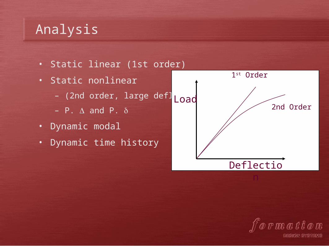
Modeling Frames
• Frames resist loads using combination of
bending and axial forces
• Columns carry vertical loads as axial forces and
resist horizontal loads by bending
• Beams resist vertical loads by bending
• Braces resist transverse loads by axial tension
or compression

Common modelling errors
• Setting all joints to be restrained
– Only the joints at the foundations
should be restrained
• Drawing a member through a joint
– Every member must run from joint
to joint. Subdivide if
necessary.Check by selecting the
member.
• Duplicating members so they touch
but are not connected to other
members
– Check using animation
• Getting loading units wrong

Load Cases
• Common load cases
– Self weight (Permanent)
– Dead load (Permanent)
– Live load (Imposed)
– Wind load
– Load combinations
• Load magnitudes are determined using
AS1170 or from first principles
• Multiframe commands
– Add Self Weight
– Add Static Load Case
– Add Combined Load Case

Dead Load
• Loads which are permanently applied to the
structure
• For joint loads, consider area which will
contribute load to that joint
• For member loads, consider area which will
load that member
• For trusses its common to apply joint loads
L
P B
w
P (N) = B (m) x L (m) x w (Pa)
1 Pa = 1 N/m2
1 N = 1 kg x g
g = 9.8 (~10)
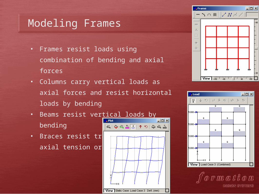
Live Load
• Loads which are temporarily applied to the
structure
• e.g. Pedestrians on the walkway
• w determined from no. of pedestrians per sq
metre and average weight per person
L
P B
w
P (N) = B (m) x L (m) x w (Pa)
1 Pa = 1 N/m2
1 N = 1 kg x g
g = 9.8 (~10)

Wind Load
• AS1170 prescribes wind load calculations
• q = 0.5 * * V2 * Cf
– q is design wind pressure Pa
– is air density = 1.2 kg/m3
– V is wind speed in m/s (assume 40 m/s)
– Cf is a shape factor (default to 1.0)
• Total load on member = L * D * q
• Load per unit length w = q * D
– D = depth of member perpendicular to air flow
• Direction of load is parallel to air flow
L
D
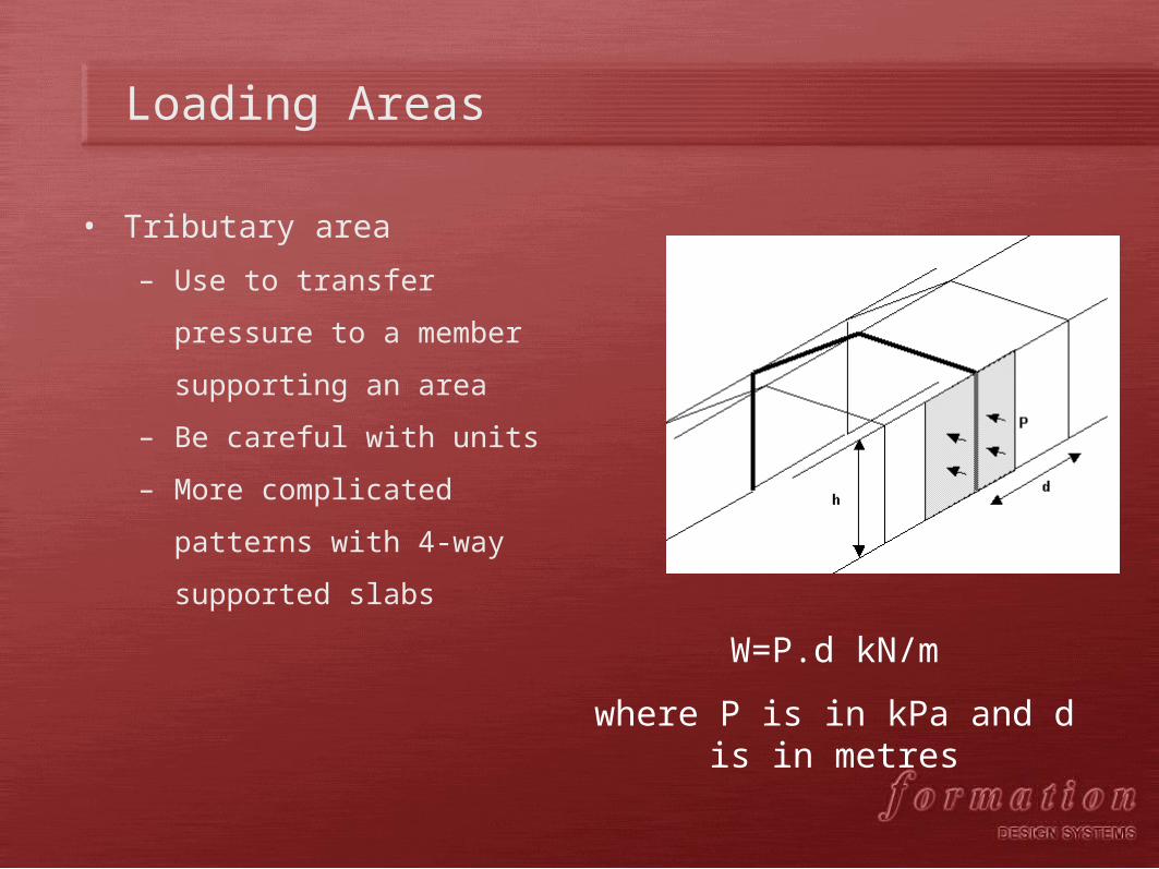
Loading Areas
• Tributary area
– Use to transfer pressure to a
member supporting an area
– Be careful with units
– More complicated patterns with
4-way supported slabs
W=P.d kN/m
where P is in kPa and d is in metres

Sample Problem Tree top walk

Tree top walk

Tree top walk

Tree top walk

Worked Example
• Tree Top Walk Truss, Walpole WA
• Length 60m, max depth 4m, max
width 3.0m, width at ends 1.0m
• Bottom chord 50mm rod, top
chords CHS168x4.8, transverse
members RHS150x50x4, bracing
CHS102x4
• www.donaldsonandwarn.com.au
Side Elevation
Plan

Worked Example Loads
• Consider self weight, dead weight, live load
and wind.
• Dead weight comes from 100mm thick jarrah
walkway
• Dead weight also comes from side railings at
70kg/m
• Live load comes from human traffic
• Wind load as per AS1170
• Self+Dead+Live+Wind
• Assume load is only applied at nodes of truss

Worked Example Dead Loads
• Self Weight using Add Self Weight load case
• Jarrah decking, 6m segment x 0.5m wide x
0.1m thick= 0.6m3
• Density of Jarrah is 800kg/m3 = 480kg = 4.8kN
• 6m handrail @ 70kg/m = 420kg = 4.2kN
• Total 9kN per node.
6m
9kN
9kN

Worked Example Live Loads
• People standing on deck
• 6m segment x 0.5m wide= 3m2
• Average person 70kg, one per square metre
• 3 x 70 = 210kg = 2.1kN per node
6m
2.1kN
2.1kN

Worked Example Wind Loads
• q = 0.5 * * V2 * Cf
– =0.5 x 1.2 * 40 x 40 = 960 Pa (~1kPa)
• Total load on member = L * D * q
• Load per unit on eg top chord
• w = q * D = 1 * 0.16 = 0.16 kN/m
• Repeat for each member of different depth
• Direction is perpendicular to length of truss

Analysis
• Static linear (1st order)
• Static nonlinear
– (2nd order, large deflection)
– P. and P.
• Dynamic modal
• Dynamic time history
Load
Deflection
1st Order
2nd Order
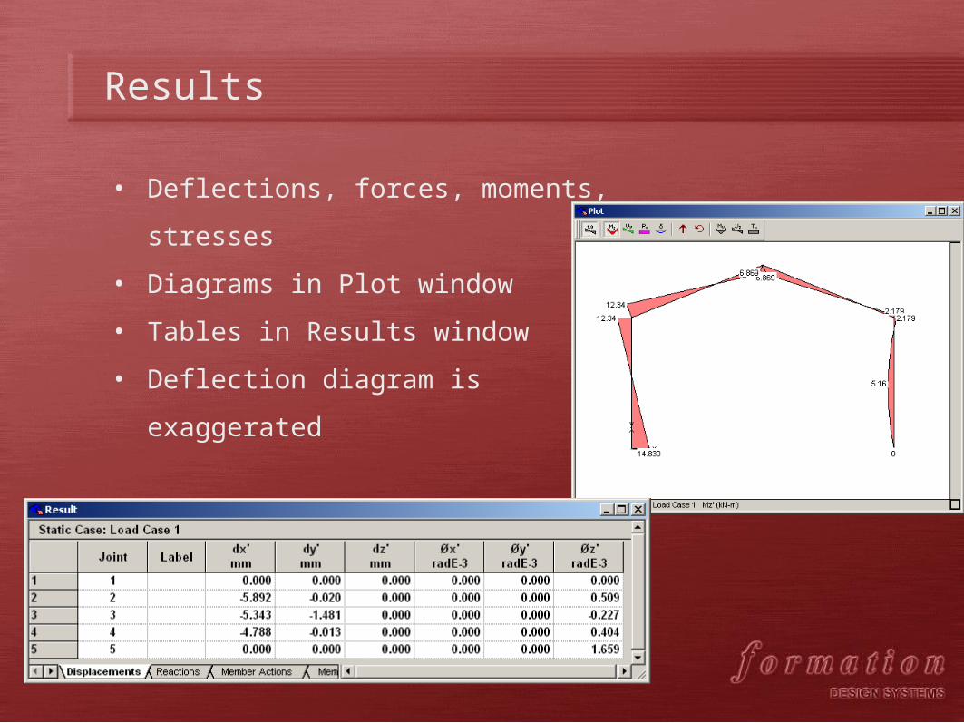
Results
• Deflections, forces, moments, stresses
• Diagrams in Plot window
• Tables in Results window
• Deflection diagram is exaggerated

Deflection Plots
• Exaggerated display of deflected shape
• Can exaggerate more or less using Scale
item in Plot dialog in Display menu
• Can set to true scale of displacement
using scale of -1
• Can overlay an action or stress as a color
on the diagram
• Can render the deflected shape
• Can animate the deflection shape and
save as an avi movie

Assignment
• Write the report as a self-contained
document
– Note any required external documents
• Use simple, annotated drawings to clarify
• Explain all assumptions
• Display intermediate as well as final working
of calculations and show all units
• Make sure units are consistent
• Use clear, simple, concise, professional
language

Student Models 1

Student Models 2
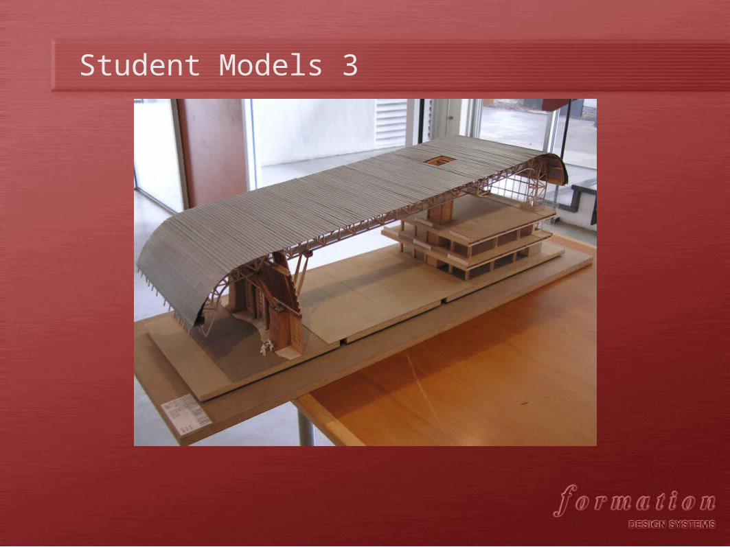
Student Models 3

Student Models 4
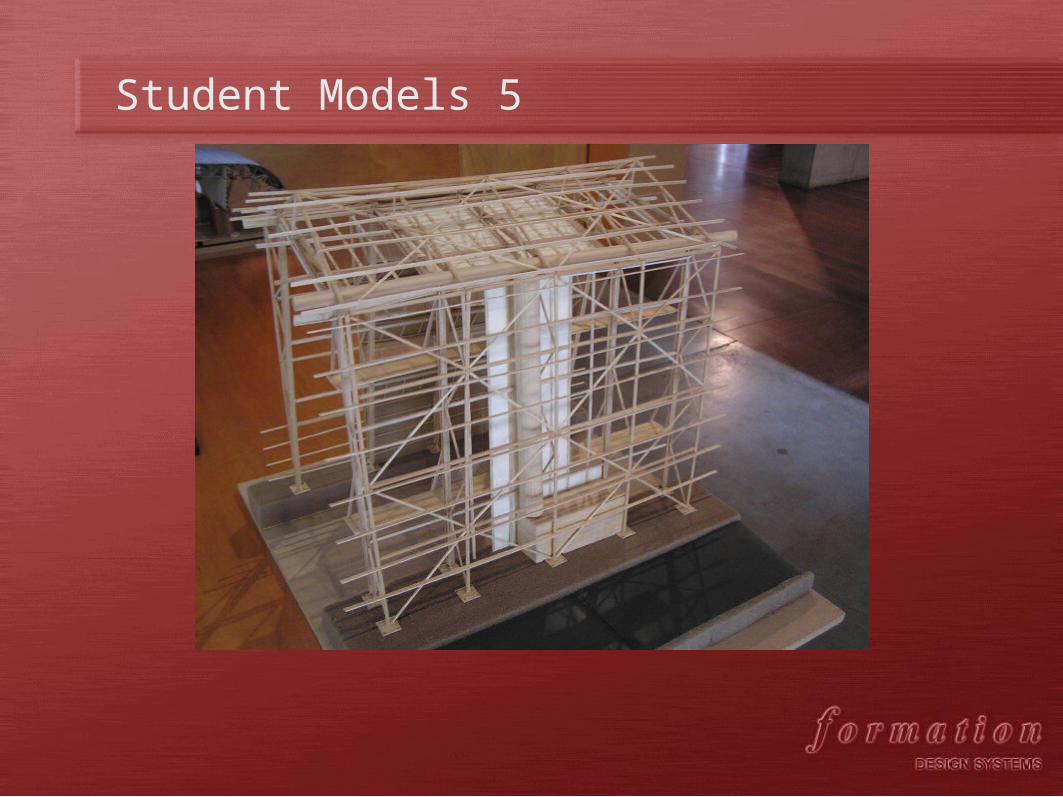
Student Models 5

Student Models 6

Student Work 1

Student Work 2

Student Work 3

Student Work 4

Student Work 5

Student Work 6
• © Formation Design Systems Pty Ltd
• PO Box 1293 Fremantle WA 6959
• Tel +61 8 9335 1522 Fax +61 8 9335 1526
• Email: [email protected]
• Web Site: www.formsys.com