
Multidisciplinary Senior Design I – P13372 Cory Behm Sakif Noor Jon Rosebrook.
29
SQUIGGLE Nano- Manipulator System Multidisciplinary Senior Design I – P13372 Cory Behm Sakif Noor Jon Rosebrook
-
Upload
solomon-craig -
Category
Documents
-
view
215 -
download
0
Transcript of Multidisciplinary Senior Design I – P13372 Cory Behm Sakif Noor Jon Rosebrook.

SQUIGGLE Nano-Manipulator System
Multidisciplinary Senior Design I – P13372Cory BehmSakif Noor
Jon Rosebrook
Project Team
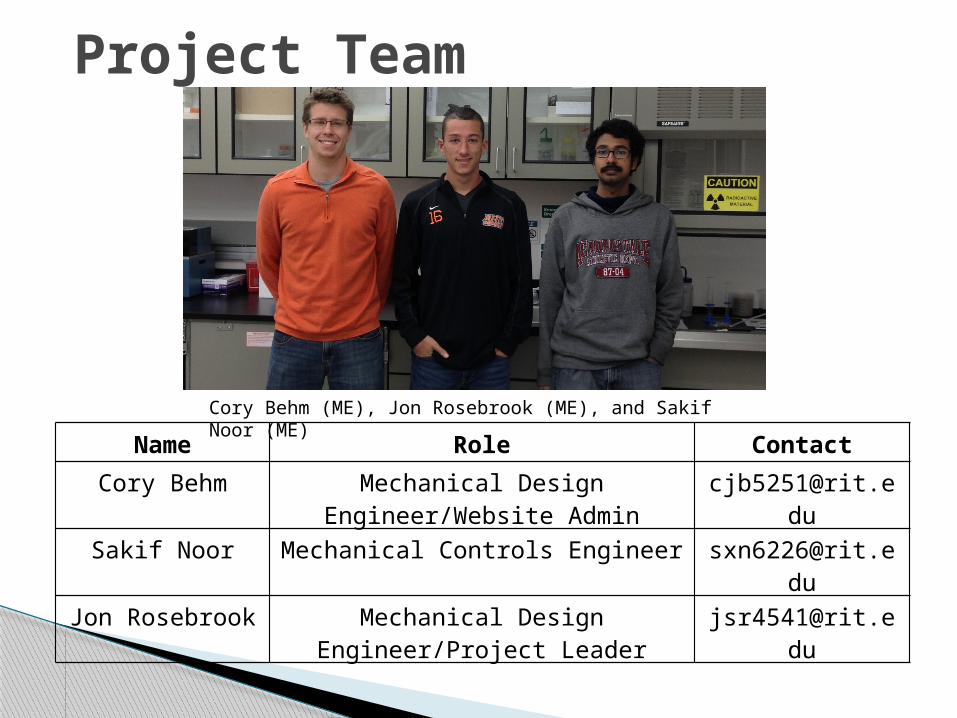
Cory Behm (ME), Jon Rosebrook (ME), and Sakif Noor (ME)Name Role Contact
Cory Behm Mechanical Design Engineer/Website Admin
Sakif Noor Mechanical Controls Engineer [email protected]
Jon Rosebrook Mechanical Design Engineer/Project Leader

Mission Statement Project Description/Summary Customer Needs and Specifications House of Quality and Pareto Chart SQUIGGLE Motors Function Tree
◦ Controls◦ Mechanical
Concepts selection – Pugh Charts Failure Modes and Effects Assessment Project Schedule Future Plans
Meeting Agenda

Design and build a low-cost, high-resolution nanomanipulator using the SQUIGGLE piezoelectric linear actuators from our sponsor, New Scale Technologies.
Demonstrate its capabilities in RIT’s Nano-Bio Interface Laboratory and compare its performance to commercially available nanomanipulators.
Mission Statement

High costs ($10-50K) and inaccessibility of nanotechnology is very limiting to research
Nanomanipulators are high resolution positioning instruments, and when used with high magnification devices, has the ability to maneuver objects thousands of times smaller than what can be seen with the human eye.
We need to develop a low-cost, high resolution, three-axis Cartesian nanomanipulator◦ SQUIGGLE piezoelectric linear actuators ◦ Sponsored by New Scale Technologies, a local company in Victor, NY
Our nanomanipulator will match the abilities of nanomanipulators currently on the market at a fraction of the cost.
To be used at RIT’s Nano-Bio Interface Laboratory
Project Description
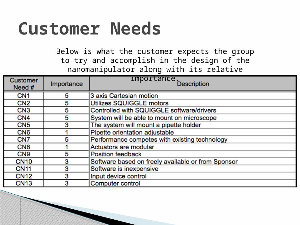
Customer NeedsBelow is what the customer expects the group to try
and accomplish in the design of the nanomanipulator along with its relative importance.
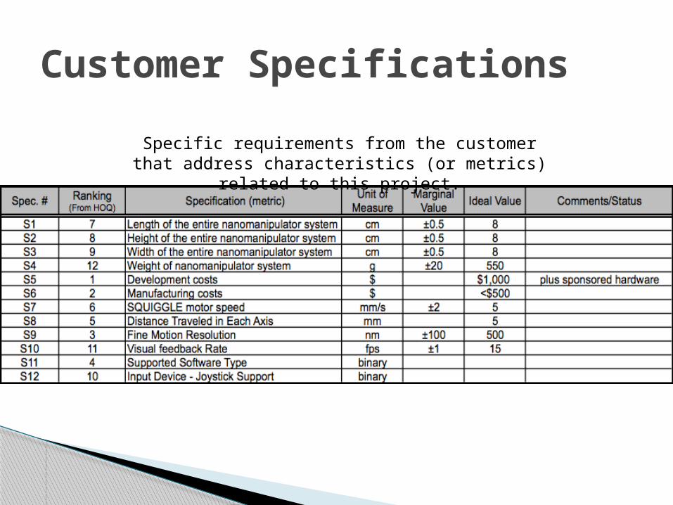
Customer Specifications
Specific requirements from the customer that address characteristics (or metrics) related to this
project.

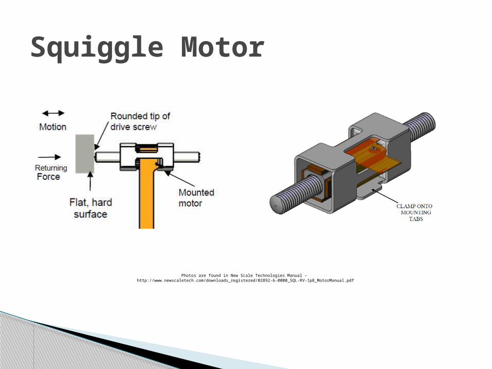
A SQUIGGLE motor consists of several piezoelectric ceramic actuators attached to a threaded nut, with a mating threaded screw inside.
Piezoelectric actuators change shape when electrically excited
Applying power to the actuators creates ultrasonic vibrations, causing the nut to vibrate in an orbit - similar to a person's hips in a "Hula Hoop."
SQUIGGLE Motor
SQUIGGLE info and pictures from http://www.newscaletech.com/squiggle_overview.html
Squiggle Motor
Photos are found in New Scale Technologies Manual – http://www.newscaletech.com/downloads_registered/02892-6-0000_SQL-RV-1p8_MotorManual.pdf

The rotating nut turns the threaded screw, creating a smooth in-and-out linear motion. Thread friction drives the shaft, directly converting rotary motion to linear motion. This means:◦ No parasitic drag - less wasted power◦ Zero backlash (with a light pre-load)◦ 500 nanometer resolution◦ High force◦ Smooth velocity at microscopic speeds◦ Off-power hold◦ Standard linear motors feature direct linear drive - no
gearbox◦ The speed and position of the threaded screw can be
precisely controlled.
Squiggle motor advantages
SQUIGGLE info from http://www.newscaletech.com/squiggle_overview.html

The House of Quality document is a diagram used for defining the relationship between customer needs and the product’s engineering specifications (or customer specifications).
The House of Quality provides a raw score of the relationship, thus allowing the team to rank the importance of completing the given relationship.
The House of Quality allows us to create a Pareto chart.
House of Quality

House of Quality
Relationships:9 = Strong3 = Moderate1 = Weak0 = No Relationship
Importance Rating:1 = Low Importance3 = Moderate Importance5 = High Importance
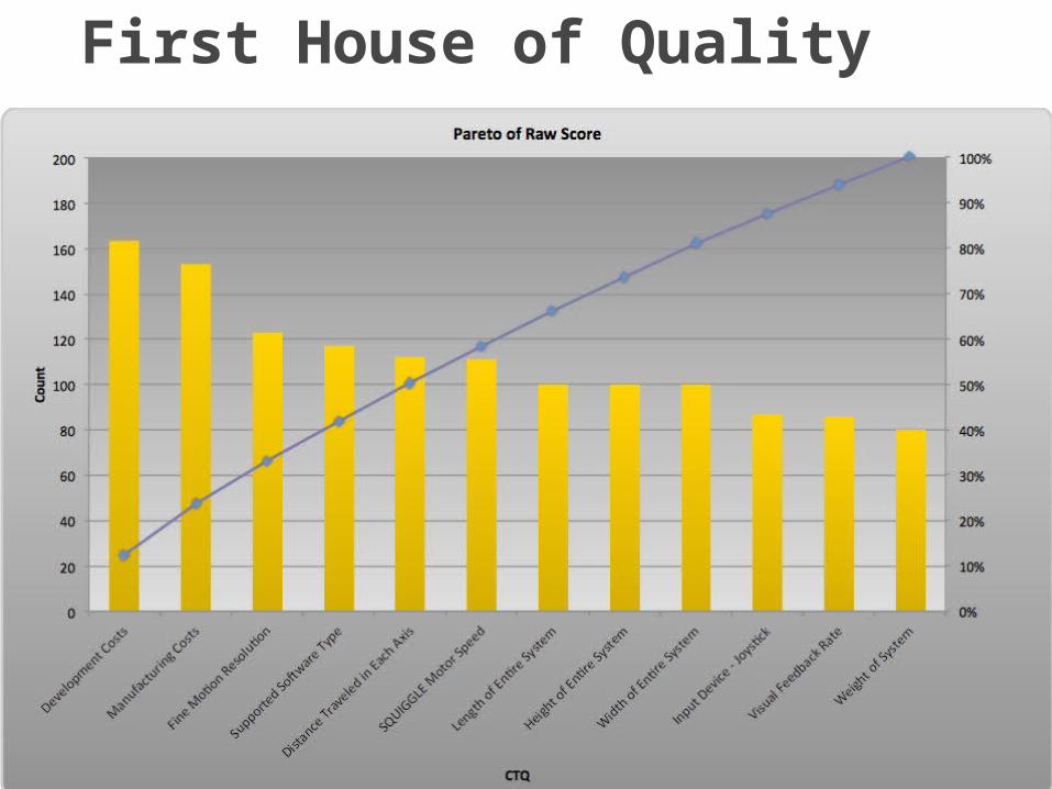
First House of Quality

Used for concept generation Answers the questions How/Why Pictorially shows where decisions need to be
made
Function tree

CONTROLS Function tree
Manipulate Pipette Under Microscope
Control
Computer Control – Local or Remote
SQUIGGLE Software-Active X
LabView Matlab Visual Basic C++
Input Device
Mouse Joystick Single Axis Knobs
Position Sensing
Optical Encoder New Scale Technologies Magnetic Encoder
Linear Sensor Rotational Sensor
Resistive Encoder/Potentiometer
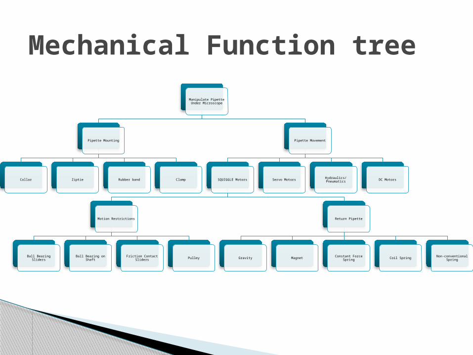
Mechanical Function tree
Manipulate Pipette Under Microscope
Pipette Mounting
Collar Ziptie Rubber band Clamp
Pipette Movement
SQUIGGLE Motors
Motion Restrictions
Ball Bearing Sliders Ball Bearing on Shaft Friction Contact Sliders Pulley
Return Pipette
Gravity Magnet Constant Force Spring Coil Spring Non-conventional Spring
Servo Motors Hydraulics/Pneumatics DC Motors
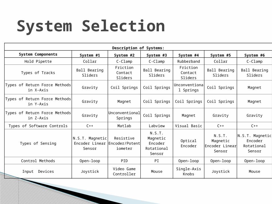
System SelectionDescription of Systems:
System Components System #1 System #2 System #3 System #4 System #5 System #6Hold Pipette Collar C-Clamp C-Clamp Rubberband Collar C-Clamp
Types of Tracks Ball Bearing Sliders Friction Contact Sliders Ball Bearing Sliders Friction Contact
Sliders Ball Bearing Sliders Ball Bearing Sliders
Types of Return Force Methods in X-Axis Gravity Coil Springs Coil Springs Unconventional Springs Coil Springs Magnet
Types of Return Force Methods in Y-Axis Gravity Magnet Coil Springs Coil Springs Coil Springs Magnet
Types of Return Force Methods in Z-Axis Gravity Unconventional Springs Coil Springs Magnet Gravity Gravity
Types of Software Controls C++ Matlab Labview Visual Basic C++ C++
Types of Sensing N.S.T. Magnetic Encoder Linear Sensor
Resistive Encoder/Potentiome
ter
N.S.T. Magnetic Encoder Rotational
SensorOptical Encoder
N.S.T. Magnetic Encoder Linear
Sensor
N.S.T. Magnetic Encoder Rotational
Sensor
Control Methods Open-loop PID PI Open-loop Open-loop Open-loop
Input Devices Joystick Video Game Controller Mouse Single-Axis Knobs Joystick Mouse
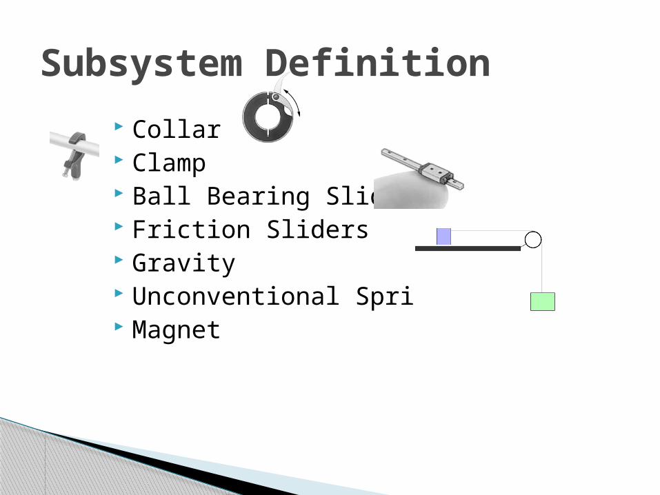
Collar Clamp Ball Bearing Sliders Friction Sliders Gravity Unconventional Spring Magnet
Subsystem Definition

System SelectionSystem Criteria System #1 System #2 System #3 System #4 System #5 System #6
Service Life + 0 0 - + 0
Manufacturing Costs + 0 0 - 0 0
Development Costs + - 0 - 0 0
# of Components + 0 0 - 0 0
Weight + - 0 - + +
Friction Loss 0 - 0 - 0 0
Ease of Implementing Return Force - - 0 - + +
Load on Motor + - 0 - 0 +
Backlash 0 - 0 - 0 -
Fine Motion Resolution 0 - 0 - 0 0
Quality of Computer Control + 0 0 + + +
Quality of Input Device + - 0 0 + 0
Serviceability/Consistency 0 - 0 0 + +
Easy to Mount/Adjust 0 + 0 - 0 +
Temperature Sensitivity + - 0 0 - +
Total - 1 10 DATUM 11 1 1
Total + 9 1 1 6 7
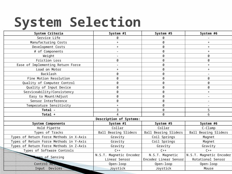
System SelectionSystem Criteria System #1 System #5 System #6
Service Life 0 0 -Manufacturing Costs + 0 +Development Costs + 0 +
# of Components - 0 +Weight - 0 0
Friction Loss 0 0 0Ease of Implementing Return Force - 0 +
Load on Motor + 0 +Backlash 0 0 -
Fine Motion Resolution 0 0 0Quality of Computer Control 0 0 0
Quality of Input Device 0 0 0Serviceability/Consistency 0 0 +
Easy to Mount/Adjust 0 0 -Sensor Interference 0 0 -
Temperature Sensitivity + 0 -Total - 3 0 5Total + 4 0 6
Description of Systems:System Components System #1 System #5 System #6
Hold Pipette Collar Collar C-ClampTypes of Tracks Ball Bearing Sliders Ball Bearing Sliders Ball Bearing Sliders
Types of Return Force Methods in X-Axis Gravity Coil Springs MagnetTypes of Return Force Methods in Y-Axis Gravity Coil Springs MagnetTypes of Return Force Methods in Z-Axis Gravity Gravity Gravity
Types of Software Controls C++ C++ C++
Types of Sensing N.S.T. Magnetic Encoder Linear Sensor
N.S.T. Magnetic Encoder Linear Sensor
N.S.T. Magnetic Encoder Rotational Sensor
Control Methods Open-loop Open-loop Open-loopInput Devices Joystick Joystick Mouse
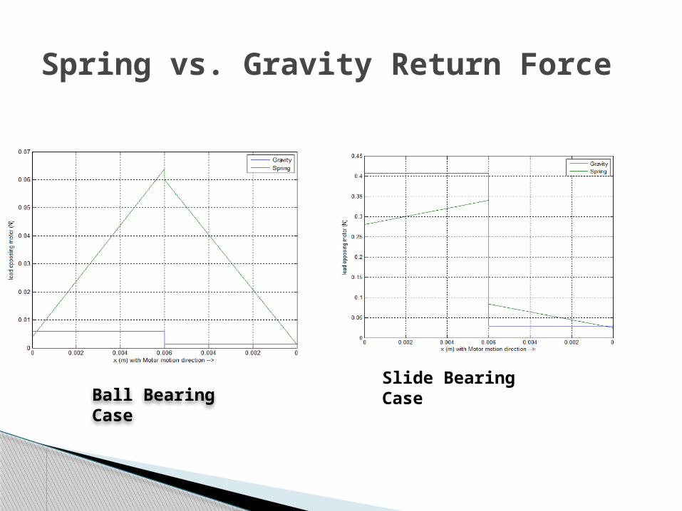
Spring vs. Gravity Return Force
Ball Bearing Case
Slide Bearing Case
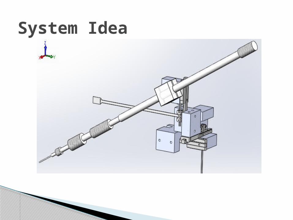
System Idea

Speed
0 2 4 6 8 10 12 14 16 180
10
20
30
40
50
60
70
f(x) = 0.0116287981197063 x³ − 0.342138970868356 x² − 0.698058412545676 x + 59.4368995463669R² = 0.999965463717602
3.3V Typical curve fit
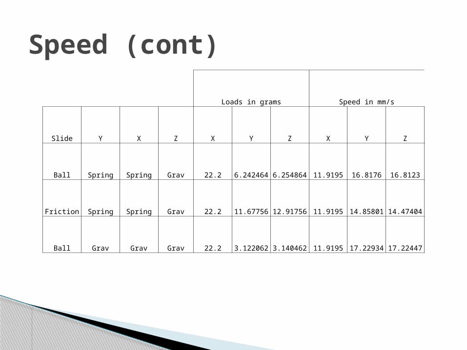
Speed (cont)
Loads in grams Speed in mm/s
Slide Y X Z X Y Z X Y Z
Ball Spring Spring Grav 22.2 6.242464 6.254864 11.9195 16.8176 16.8123
Friction Spring Spring Grav 22.2 11.67756 12.91756 11.9195 14.85801 14.47404
Ball Grav Grav Grav 22.2 3.122062 3.140462 11.9195 17.22934 17.22447
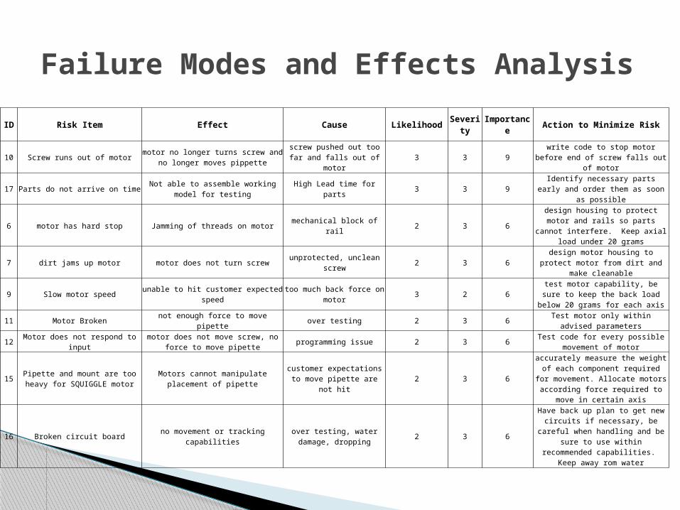
Failure Modes and Effects Analysis
ID Risk Item Effect Cause Likelihood Severity Importance Action to Minimize Risk
10 Screw runs out of motormotor no longer turns screw and no
longer moves pippettescrew pushed out too far and
falls out of motor3 3 9
write code to stop motor before end of screw falls out of motor
17 Parts do not arrive on timeNot able to assemble working model for
testingHigh Lead time for parts 3 3 9
Identify necessary parts early and order them as soon as possible
6 motor has hard stop Jamming of threads on motor mechanical block of rail 2 3 6design housing to protect motor and rails so parts cannot interfere. Keep
axial load under 20 grams
7 dirt jams up motor motor does not turn screw unprotected, unclean screw 2 3 6design motor housing to protect motor
from dirt and make cleanable
9 Slow motor speed unable to hit customer expected speed too much back force on motor 3 2 6test motor capability, be sure to keep
the back load below 20 grams for each axis
11 Motor Broken not enough force to move pipette over testing 2 3 6Test motor only within advised
parameters
12 Motor does not respond to inputmotor does not move screw, no force to
move pipetteprogramming issue 2 3 6
Test code for every possible movement of motor
15Pipette and mount are too heavy for
SQUIGGLE motorMotors cannot manipulate placement of
pipettecustomer expectations to move pipette are not hit
2 3 6
accurately measure the weight of each component required for movement.
Allocate motors according force required to move in certain axis
16 Broken circuit board no movement or tracking capabilitiesover testing, water damage,
dropping2 3 6
Have back up plan to get new circuits if necessary, be careful when handling
and be sure to use within recommended capabilities. Keep away rom water

Failure Modes and Effects Analysis
2 Slide sticks on rail Motor does not move accurately too much friction on rail 2 2 4Purchase rails with least amount of
friction within a reasonable price
3 Spring breaksNo preload on motor, inaccurate
movementsOver use 2 2 4 learn limits on springs
1 Motor falls out of mountMotor moves instead of moving
pipettecrack in mount 1 3 3 Make mount out of durable material
4 Lateral Force on screw Motor is stripped/brokenforce pushing laterally on
screw1 3 3
Rail system only allows force along axis of screw, screws protected from
being touched
5 FPC broken Motor does not work too much bending 1 3 3design so FPC is not bent in a smaller
radius than 1mm
8 improper position reading position of motor unknownimproper placement of guide
magnet1 3 3
follow newscale guidelines for placing guide magnet, stick to surface that
magnet will not come off without being forced
13 Screw is strippedmotor does not turn screw in axis, no
force to move pipetteover use/testing of screw 1 3 3
create plan to acquire back up screws if necessary
14 Clamp does not hold pipette improper movement of pipette wrong size clamp for pipette 1 3 3take accurate measurements of
pipette or design specific pipette for manipulator
18 Nanomanipulator mount is too weaknanomanipulator does not attach to
microscopewrong material type for
mounting nanomanipulator1 2 2
Understand and measure weights of nanomanipulator, choose material
capable of support with microscope attachment capabilities

Feasibility Analysis Detailed Design Output: BOM, Drawings,
Schematics, Flow Charts Continue to Update Risk Assessment Plan to meet Customer Needs & Design
Specs, including Preliminary Test Plan Detailed Design Review execution Final Project Review – Prepare for MSD II
Future plans
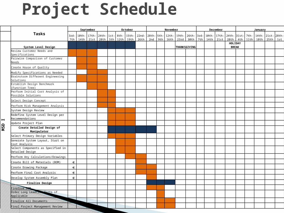
Project ScheduleTasks
September October November December January
3rd-7th10th-14th
17th-21st
24th-28th
1st-5th
8th-12th
15th-19th
22nd-26th
28th-2nd
5th-9th
12th-16th
19th-23rd
26th-30th
3rd-7th
10th-14th
17th-21st
24th-28th
31st-4th
7th-11th
14th-18th
21st-25th
28th-1st
MSD I
System Level Design THANKSGIVING HOLIDAY BREAK
Review Customer Needs and Specifications
Pairwise Comparison of Customer Needs
Create House of Quality
Modify Specifications as Needed
Brainstorm Different Engineering Solutions
Establish Design Benchmark (Function Tree)
Perform Initial Cost Analysis of Possible Solutions
Select Design Concept
Perform Risk Management Analysis System Design Review Redefine System Level Design per Recommendations Update Project Plan
Create Detailed Design of Manipulator Select Primary Design Variables Generate System Layout, Start on Cost Analysis Select Components as Specified in Detailed Design
Perform Any Calculations/Drawings
Create Bill of Materials (BOM)
Create Drawing Package
Perform Final Cost Analysis
Develop System Assembly Plan
Finalize Design
Finalize BOM
Order Long Leadtime Parts if Applicable
Finalize All Documents
Final Project Management Review

Questions???
Thank you for coming!