Multidisciplinary Design Optimization with HAWTOpt2Multidisciplinary Design Optimization with...
35
Multidisciplinary Design Optimization with HAWTOpt2 Michael McWilliam, Frederik Zahle Danish Technical University
Transcript of Multidisciplinary Design Optimization with HAWTOpt2Multidisciplinary Design Optimization with...

Multidisciplinary Design Optimization with HAWTOpt2
Michael McWilliam, Frederik Zahle
Danish Technical University

Outline
• The HAWTOpt2 Framework
• Conventional Blade Optimization
• Bend-Twist Coupled Blades
• Smart Blades
• Closing statements
2 DTU Wind Energy HAWTOpt2 November 2, 2017

The HAWTOpt2 Framework
3 DTU Wind Energy HAWTOpt2 November 2, 2017

The HAWTOpt2 Framework
HawtOpt2: Tool for Aero-Servo-Elastic Optimization of WindTurbines
HawtOpt2 provides workflows that coupleaeroelastic and structural solverstogether to allow for:
• Simultaneous and fully coupledoptimization of lofted blade shape and thestructural design of a blade.
• Exploration of the many often conflictingobjectives and constraints in a rotor design.
• Detailed tailoring of aerodynamic andstructural properties.
• Constraints on specific fatigue damageloads.
• Placement of natural frequencies.
4 DTU Wind Energy HAWTOpt2 November 2, 2017

The HAWTOpt2 Framework
HawtOpt2: Tool for Aero-Servo-Elastic Optimization of WindTurbines
• Underlying framework: OpenMDAO(written in Python),
• Optimization algorithm: IPOPT interfacedthrough PyOptSparse,
• Geometric parameterisation: FUSED-Wind,
• HAWCStab2/HAWC2 interface:
• AEP,• Frequency placement,• Fatigue in frequency domain,• Reduced/full DLB in time domain,
• BECAS interface:
• Calculation of stiffness properties,• Calculation of material failure andfatigue damage.
4 DTU Wind Energy HAWTOpt2 November 2, 2017

The HAWTOpt2 Framework
Aero-elastic Solvers: HAWCStab2 and HAWC2
• Structural model: geometricallynon-linear Timoshenko finite beamelement model.
• Aerodynamic model: unsteady BEMincluding effects of shed vorticity anddynamic stall and dynamic inflow.
• HAWCStab2: Analytic linearizationaround an aero-structural steady stateignoring gravitational forces.
• HAWCStab2: Fatigue damagecalculated in frequency domain(including effect of ATEFs) based onthe linear model computed byHAWCStab2.
Image from: Sønderby and Hansen, Wind Energy, 2014
5 DTU Wind Energy HAWTOpt2 November 2, 2017

The HAWTOpt2 Framework
Structural Solver: BECAS (BEam Cross section AnalysisSoftware)
• Finite element based tool foranalysis of the stiffness and massproperties of beam cross sections.
• Correctly predicts effects stemmingfrom material anisotropy andinhomogeneity in sections ofarbitrary geometry (e.g., allcoupling terms).
• Detailed stress analysis based onexternally computed extreme loads.
6 DTU Wind Energy HAWTOpt2 November 2, 2017

The HAWTOpt2 Framework
Estimation of Extreme loads using HAWC2
• Fully resolved time simulations of all DLCs (+1000 simulations) is timeconsuming, and inclusion of turbulence is not suited for gradient based MDO,
• A reduced DLB has been developed, which requires <40 cases and omitsturbulence inflow.
7 DTU Wind Energy HAWTOpt2 November 2, 2017
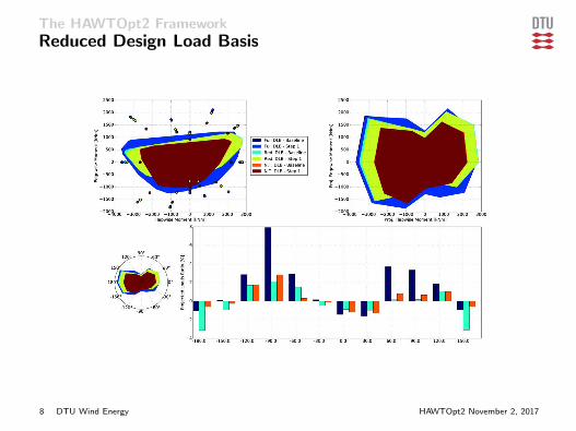
The HAWTOpt2 Framework
Reduced Design Load Basis
8 DTU Wind Energy HAWTOpt2 November 2, 2017

The HAWTOpt2 Framework
The HAWTOpt2 Work-flow
• IPOPT Optimization Algorithm
• Uses OpenMDAO for the glue code
• Cross Section Module (BECAS)
• Steady and Unsteady Aeroelastic Models (HAWCStab2 & HAWC2)
9 DTU Wind Energy HAWTOpt2 November 2, 2017

The HAWTOpt2 Framework
Internal Structure Design Variables
• DP’s control web positions and panel sizes
• Thickness design variables for main load carrying laminates
• Can have fiber angle design variables (not used here)
TRIAX
UNIAX
TRIAX
UNIAXs=−1
s=0.
s=1
DP3
DP5
DP7
DP8DP9
DP10
DP13
DP0
DP4
DP6UNIAX
TRIAX
TRIAX
10 DTU Wind Energy HAWTOpt2 November 2, 2017
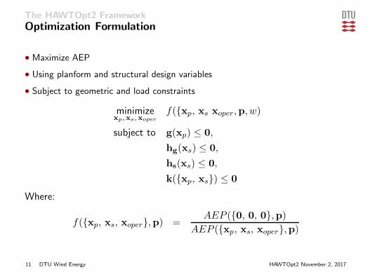
The HAWTOpt2 Framework
Optimization Formulation
• Maximize AEP
• Using planform and structural design variables
• Subject to geometric and load constraints
minimizexp,xs,xoper
f({xp, xs xoper,p, w)
subject to g(xp) ≤ 0,
hg(xs) ≤ 0,
hs(xs) ≤ 0,
k({xp, xs}) ≤ 0
Where:
f({xp, xs, xoper},p) =AEP ({0, 0, 0},p)
AEP ({xp, xs, xoper},p)
11 DTU Wind Energy HAWTOpt2 November 2, 2017

The HAWTOpt2 Framework
Design Variables
Parameter # of DVs CommentChord 6 -Twist 5 Root twist fixedRelative thickness 3 Root and tip relative thickness fixedBlade prebend 4 -Blade precone 1 -Blade length 1 -Tip-speed ratio 1 -Trailing edge uniax 2 Pressure/suction sideTrailing edge triax 2 Pressure/suction sideTrailing panel triax 2 Pressure/suction sideSpar cap uniax 4 Pressure/suction sideLeading panel triax 2 Pressure/suction sideLeading edge uniax 2 Pressure/suction sideLeading edge triax 2 Pressure/suction sideDP4 5 Pressure side spar cap position/rear web attachmentDP5 5 Pressure side spar cap position/front web attachmentDP8 5 Suction side spar cap position/front web attachmentDP9 5 Suction side spar cap position/rear web attachmentTotal 65
12 DTU Wind Energy HAWTOpt2 November 2, 2017
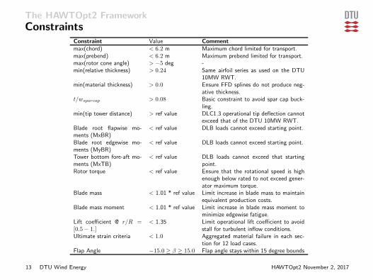
The HAWTOpt2 Framework
ConstraintsConstraint Value Commentmax(chord) < 6.2 m Maximum chord limited for transport.max(prebend) < 6.2 m Maximum prebend limited for transport.max(rotor cone angle) > −5 deg -min(relative thickness) > 0.24 Same airfoil series as used on the DTU
10MW RWT.min(material thickness) > 0.0 Ensure FFD splines do not produce neg-
ative thickness.t/wsparcap > 0.08 Basic constraint to avoid spar cap buck-
ling.min(tip tower distance) > ref value DLC1.3 operational tip deflection cannot
exceed that of the DTU 10MW RWT.Blade root flapwise mo-ments (MxBR)
< ref value DLB loads cannot exceed starting point.
Blade root edgewise mo-ments (MyBR)
< ref value DLB loads cannot exceed starting point.
Tower bottom fore-aft mo-ments (MxTB)
< ref value DLB loads cannot exceed that startingpoint.
Rotor torque < ref value Ensure that the rotational speed is highenough below rated to not exceed gener-ator maximum torque.
Blade mass < 1.01 * ref value Limit increase in blade mass to maintainequivalent production costs.
Blade mass moment < 1.01 * ref value Limit increase in blade mass moment tominimize edgewise fatigue.
Lift coefficient @ r/R =[0.5− 1.]
< 1.35 Limit operational lift coefficient to avoidstall for turbulent inflow conditions.
Ultimate strain criteria < 1.0 Aggregated material failure in each sec-tion for 12 load cases.
Flap Angle −15.0 ≥ β ≥ 15.0 Flap angle stays within 15 degree bounds
13 DTU Wind Energy HAWTOpt2 November 2, 2017

Conventional Blade Optimization
• Aero-elastic optimization
• Based on the DTU 10MW RWT
• Original DTU 10MW RWT is a CP optimized design
• No sweep or material coupling allowed in the optimization
• All other design variables allowed to vary
14 DTU Wind Energy HAWTOpt2 November 2, 2017

Conventional Blade Optimization
Optimized Blade Planform
• Blade length increased to 94.3 m (9.2% increase),
• Slender blade planform, with slightly thicker airfoils,
• Increased prebend to avoid tower clearance constraint.
0 20 40 60 80 100Blade running length [m]
0
1
2
3
4
5
6
7
Cho
rd le
ngth [m
]
BaselineNew design
0 20 40 60 80 100Blade running length [m]
−15
−10
−5
0
5
10
Blade
twist [de
g.]
BaselineNew design
0 20 40 60 80 100Blade running length [m]
20
30
40
50
60
70
80
90
100
Relative thickn
ess [%
]
BaselineNew design
0 20 40 60 80 100Blade radial coordiante [m]
7
6
5
4
3
2
1
0
1
Blade out of plane coordinate [-] Baseline
New design
15 DTU Wind Energy HAWTOpt2 November 2, 2017
Conventional Blade Optimization
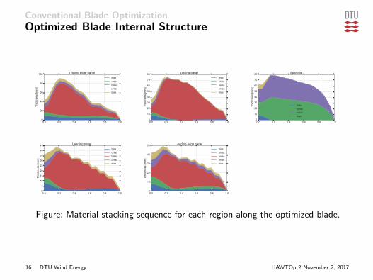
Optimized Blade Internal Structure
0.0 0.2 0.4 0.6 0.8 1.00
20
40
60
80
100
Thickn
ess [m
m]
Trailing edge paneltriaxuniaxbalsauniaxtriax
0.0 0.2 0.4 0.6 0.8 1.00
10
20
30
40
50
60
70
80
Thickn
ess [m
m]
Trailing paneltriaxuniaxbalsauniaxtriax
0.0 0.2 0.4 0.6 0.8 1.00
10
20
30
40
50
60
70
80
Thickn
ess [m
m]
Spar cap
triaxuniaxuniaxtriax
0.0 0.2 0.4 0.6 0.8 1.00
5
10
15
20
25
30
35
40
45
Thickn
ess [m
m]
Leading paneltriaxuniaxbalsauniaxtriax
0.0 0.2 0.4 0.6 0.8 1.00
10
20
30
40
50Th
ickn
ess [m
m]
Leading edge paneltriaxuniaxbalsauniaxtriax
Figure: Material stacking sequence for each region along the optimized blade.
16 DTU Wind Energy HAWTOpt2 November 2, 2017

Conventional Blade Optimization
Optimized Lofted Blade
• Internal structure optimized with very few geometric constraints,
• Main laminates placed forward in the cross-section and angled,
17 DTU Wind Energy HAWTOpt2 November 2, 2017

Conventional Blade Optimization
Optimized Load Distributions
0 20 40 60 80 100Blade radial coordinate [m]
0.1
0.2
0.3
0.4
0.5
0.6
0.7
0.8
0.9
1.0
Loca
l thr
ust c
oeffi
cien
t [-]
wsp=7.00wsp=8.00wsp=9.00wsp=10.00wsp=11.00
0 20 40 60 80 100Blade radial coordinate [m]
0
1000
2000
3000
4000
5000
6000
7000
8000
9000
Normal force [N/m]
wsp=7.00wsp=8.00wsp=9.00wsp=10.00wsp=11.00
0 20 40 60 80 100Blade radial coordinate [m]
−6
−5
−4
−3
−2
−1
0
1
Blade
torsion [deg
]
wsp=7.00wsp=8.00wsp=9.00wsp=10.00wsp=11.00
0 20 40 60 80 100Blade radial coordinate [m]
0
5
10
15
20
Angle of attack [deg]
wsp=7.00wsp=8.00wsp=9.00wsp=10.00wsp=11.00
Figure: Blade local thrust coefficients and normal forces (upper), and blade torsionand angle of attach (lower) for a range of wind speeds.
18 DTU Wind Energy HAWTOpt2 November 2, 2017

Conventional Blade Optimization
A closer look at the structural tailoring
• Bend twist coupling occurs ”hands off” due to the use of a fully coupled MDOapproach,
• Achieved through a forward movement of the shear center and reduction oftorsional stiffness,
• The resulting coupling is referred to as ”shear twist coupling”,
• The angling of the main laminates results in better alignment of the mainloading direction and elastic axis,
• This coupling does not suffer from loss in flapwise stiffness, making it moreattractive that e.g. material coupling.
19 DTU Wind Energy HAWTOpt2 November 2, 2017

Conventional Blade Optimization
Power Curve
• Steady state AEP increased by 11.1%,
• Turbulent power curve evaluated at TI=10%, six seeds, AEP gain of 8.7%,
• Aeroelastically tailored blade loses power in turbulent conditions.
0 5 10 15 20 25Wind speed [m/s]
0
2000
4000
6000
8000
10000
12000
Mecha
nical P
ower [kW]
BaselineNew design
4 6 8 10 12 14Wind speed [m/s]
0.5
0.6
0.7
0.8
0.9
1.0
1.1
1.2
Pmek_t/Pmek_s [-]
BaselineNew design
Figure: Power curve for the optimized blade compared to the baseline design forsteady state conditions (dotted lines) and turbulent power curve with 10%reference TI (left), and the ratio between the turbulent and steady state powercurves (right).
20 DTU Wind Energy HAWTOpt2 November 2, 2017

Bend-twist Coupled Blades
• Investigated both geometric and material coupled blades
• Based on a 100kW wind turbine with a 10m blade length
• 3 different cases investigated:
• KB1: Reference optimization where torsion is constrained• KB2: Optimization with sweep• KB3: Optimization where fiber angle could vary in the spar cap
21 DTU Wind Energy HAWTOpt2 November 2, 2017

Bend-twist Coupled Blades
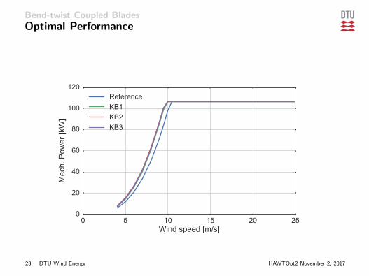
Optimal Performance
Quantity KB1 KB2 Diff. KB3 Diff.
AEP [kWh] 405166 412457 1.018 408943 1.009(C=7, k=2)Improvement 15.9% 18.0% 17.0%Blade length [m] 11.064 11.35 1.026 11.231 1.015blade mass [kg] 256.87 257.14 0.999 256.85 0.999TSR [-] 10.084 10.625 1.054 9.779 0.970
• Baseline AEP: 349586 kWh
22 DTU Wind Energy HAWTOpt2 November 2, 2017
Bend-twist Coupled Blades
Optimal Performance
0 5 10 15 20 25Wind speed [m/s]
0
20
40
60
80
100
120
Mech. Power [kW]
ReferenceKB1KB2KB3
23 DTU Wind Energy HAWTOpt2 November 2, 2017

Bend-twist Coupled Blades
Optimal Performance
0 5 10 15 20 25Wind speed [m/s]
0.98
1.00
1.02
1.04
1.06
1.08
1.10M
ech.
Pow
er ra
tio [-
]KB2/KB1KB3/KB1
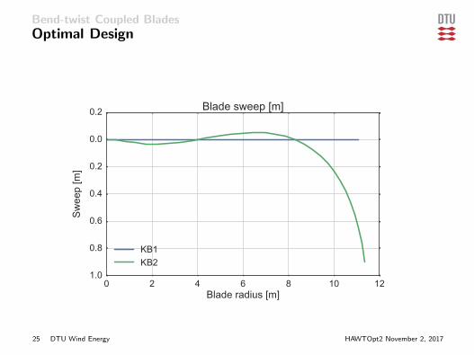
• Better improvement achieved with geometric coupling
• Optimization limited by tip deflection constraint
• Off-axis fibers reduce stiffness
24 DTU Wind Energy HAWTOpt2 November 2, 2017
Bend-twist Coupled Blades
Optimal Design
0 2 4 6 8 10 12Blade radius [m]
−1.0
−0.8
−0.6
−0.4
−0.2
0.0
0.2
Swee
p [m
]
Blade sweep [m]
KB1KB2
25 DTU Wind Energy HAWTOpt2 November 2, 2017
Bend-twist Coupled Blades
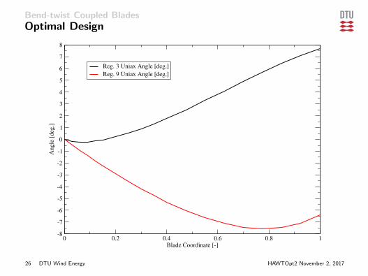
Optimal Design
0 0.2 0.4 0.6 0.8 1Blade Coordinate [-]
-8
-7
-6
-5
-4
-3
-2
-1
0
1
2
3
4
5
6
7
8A
ngle
[deg
.]
Reg. 3 Uniax Angle [deg.]
Reg. 9 Uniax Angle [deg.]
26 DTU Wind Energy HAWTOpt2 November 2, 2017

Smart Blades
• Investigated the AEP increase for quasi-static flap actuation
• Based on the DTU 10MW RWT
• Optimized both the blade and the flap settings
• 3 different cases investigated:
• DTU 10MW with just the flap• Baseline, blade optimization without the flap• Baseline with the flaps• Combined blade and flap optimization
27 DTU Wind Energy HAWTOpt2 November 2, 2017

Smart Blades
Flap Configuration
• Flap only deflected in below rated conditions
• Flap operates in a quasi-steady mode
28 DTU Wind Energy HAWTOpt2 November 2, 2017

Smart Blades
Optimal Solution
• Flaps provide a 1% improvement for aero-elastically optimal blades
• Flaps only gives 0.51% improvement for CP optimal blades
Original w/ Flaps Baseline Baseline w/ Flaps Co-Optimization0
1
2
3
4
5
6
7
8
9
10
11
12
13
14
15
16
Per
cen
t Im
pro
vem
ent
in A
EP
29 DTU Wind Energy HAWTOpt2 November 2, 2017

Smart Blades
Flap Deflection
• Both start at negative angles, increase the decrease with increasing wind speed
• Co-design allowed more aggressive utilization of the flaps
6 7 8 9 10 11 12 13Wind Speed [m/s]
-5
0
5
10
15
Fla
p D
efle
ctio
n [
deg
]
DTU 10 MW RWT w/ Flap Add-on
Baseline Design w/ Flap Add-on
Co-Design
30 DTU Wind Energy HAWTOpt2 November 2, 2017

Smart Blades
Power Gain From Flaps
4 5 6 7 8 9 10 11 12 13Wind Speed [m/s]
-20
0
20
40
60
80
100
120
140
160
180
200
220
240
260
280
300
320
Gai
n i
n A
ero
dy
nam
ic P
ow
er [
kW
]
DTU 10 MW RWT w/ Flaps
Baseline w/ Flaps
Co-Design
Co-Design vs. Baseline
31 DTU Wind Energy HAWTOpt2 November 2, 2017
Smart Blades
Conclusions
• Wind turbine rotor design is increasingly complicated
• Multiple disciplines in competition• Innovations affect all aspects of the design
• Multidisciplinary design optimization can overcome this complexity
• It can provide better rotor designs• Reveal new innovations• Evaluate new load aleviation technology
32 DTU Wind Energy HAWTOpt2 November 2, 2017
Smart Blades
Thank-you for your interest
Comments or Questions?
33 DTU Wind Energy HAWTOpt2 November 2, 2017