Multidisciplinary Approach for Developing a New …bionics.seas.ucla.edu/publications/CP_23.pdf ·...
7
BioRob 2006- The first IEEE / RAS-EMBS International Conference on Biomedical Robotics and Biomechatronics Pisa, Tuscany, Italy, February 20-22, 2006 Multidisciplinary Approach for Developing a New Minimally Invasive Surgical Robotic System Mitchell J.H. Lum 1 , Denny Trimble 2 , Jacob Rosen 1 , Kenneth Fodero II 1 , H. Hawkeye King 1 , Ganesh Sankaranarayanan 1 , Jesse Dosher 1 , Rainer Leuschke 1 , Brandon Martin-Anderson 1 , Mika N. Sinanan 3 , Blake Hannaford 1 1 Dept. of Electrical Engineering, 2 Dept. of Mechanical Engineering, 3 Dept. of Surgery University of Washington Seattle, WA 98195-2500, USA mitchlum, dennyt ,rosen, kfodero, hawkeye1, ganeshs, jdosher, rainer, bmander, mssurg,blake, @u.washington.edu .Abstract – The synergy between fundamental science, engineering and medicine is constantly evolving while providing physicians with better tools and techniques for delivering patients effective health care. Minimally invasive surgery (MIS) revolutionized the way in which a number of surgical procedures are performed resulting in quicker postoperative recovery times. Surgical robotics provides a new paradigm to further improve MIS interventions. As part of an extensive experimental protocol, the kinematics and the dynamics of MIS tools were acquired from 30 surgeons who performed seven different minimally invasive surgical tasks. These tasks included tissue manipulation, tissue dissection and suturing in-vivo while using the Blue Dragon system and a porcine model. This database served as a design specification for a kinematic optimization of a spherical surgical robotic manipulator. Following the optimization that determined key geometrical dimensions of the robot, a 7-DOF cable-actuated surgical manipulator was designed and integrated, providing all the degrees of freedom of manual MIS as well as wrist joints located at the surgical end-effector. The surgical robotic system is teleoperated utilizing a single bi-directional UDP socket via a remote master device. This multidisciplinary approach of designing and optimizing the surgical robotic system will lead to a seamless integration into the operating room of the future. Index Terms – Surgical Robot, spherical, teleoperation, telesurgery I. INTRODUCTION Innovation in surgery allows surgeons to provide better healthcare to their patients. In particular, minimally invasive . * This work is partially supported by US Army, Medical Research and Material Command, grant number DAMD17-1-0202 surgery (MIS) reduces postoperative hospital stays to just over a day compared to over a week when an open surgical procedure is performed. More precise, less invasive and inherently safer techniques and equipment are the prime aims of the evolutionary processes in healthcare. Integrating robotic systems into the operating room has been the focus of significant research for nearly two decades (for review – see [1-5]). Through an extensive multidisciplinary research effort a database was acquired including the kinematics and dynamics of surgical tools [8,9] in a MIS setup. This database served as the foundation for defining the engineering specifications and requirements of a multi-arm surgical robotic system. Physical mock-ups of the candidate mechanism were tested both in dry and wet lab conditions to validate the concept, followed by a comprehensive kinematic optimization aimed to maximize performance and minimize the size of the manipulator [11]. Through an extensive design process, a compact and dexterous robotic surgical manipulator as well as the supporting control hardware and software was developed. This paper provides a comprehensive overview addressing the different aspects of developing a MIS 7-DOF surgical robotic system. II. CLINICAL REQUIREMENTS - AN EXPERIMENTAL APPROACH Evaluation of procedural skills in surgery can be performed utilizing three different modalities: during actual open or minimally invasive clinical procedures; in physical or virtual reality simulators with or without haptic feedback; and during interaction with surgical robotic systems. One element that all these modalities have in common is the human-machine interface in which visual, kinematic, dynamic, and haptic information are shared. This interface, rich with multi-dimensional data, is a valuable source of objective information that can be used to assess technical
Transcript of Multidisciplinary Approach for Developing a New …bionics.seas.ucla.edu/publications/CP_23.pdf ·...

BioRob 2006- The first IEEE / RAS-EMBS International Conference on Biomedical Robotics and Biomechatronics Pisa, Tuscany, Italy, February 20-22, 2006
Multidisciplinary Approach for Developing a New Minimally Invasive Surgical Robotic System
Mitchell J.H. Lum1, Denny Trimble2, Jacob Rosen1, Kenneth Fodero II1, H. Hawkeye King1, Ganesh Sankaranarayanan1, Jesse Dosher1, Rainer Leuschke1, Brandon Martin-Anderson1,
Mika N. Sinanan3, Blake Hannaford1
1Dept. of Electrical Engineering, 2Dept. of Mechanical Engineering, 3Dept. of Surgery University of Washington
Seattle, WA 98195-2500, USA mitchlum, dennyt ,rosen, kfodero, hawkeye1, ganeshs, jdosher, rainer, bmander, mssurg,blake, @u.washington.edu
.Abstract – The synergy between fundamental science, engineering and medicine is constantly evolving while providing physicians with better tools and techniques for delivering patients effective health care. Minimally invasive surgery (MIS) revolutionized the way in which a number of surgical procedures are performed resulting in quicker postoperative recovery times. Surgical robotics provides a new paradigm to further improve MIS interventions. As part of an extensive experimental protocol, the kinematics and the dynamics of MIS tools were acquired from 30 surgeons who performed seven different minimally invasive surgical tasks. These tasks included tissue manipulation, tissue dissection and suturing in-vivo while using the Blue Dragon system and a porcine model. This database served as a design specification for a kinematic optimization of a spherical surgical robotic manipulator. Following the optimization that determined key geometrical dimensions of the robot, a 7-DOF cable-actuated surgical manipulator was designed and integrated, providing all the degrees of freedom of manual MIS as well as wrist joints located at the surgical end-effector. The surgical robotic system is teleoperated utilizing a single bi-directional UDP socket via a remote master device. This multidisciplinary approach of designing and optimizing the surgical robotic system will lead to a seamless integration into the operating room of the future.
Index Terms – Surgical Robot, spherical, teleoperation,
telesurgery I. INTRODUCTION
Innovation in surgery allows surgeons to provide better healthcare to their patients. In particular, minimally invasive
. * This work is partially supported by US Army, Medical Research and Material Command, grant number DAMD17-1-0202
surgery (MIS) reduces postoperative hospital stays to just over a day compared to over a week when an open surgical procedure is performed. More precise, less invasive and inherently safer techniques and equipment are the prime aims of the evolutionary processes in healthcare. Integrating robotic systems into the operating room has been the focus of significant research for nearly two decades (for review – see [1-5]).
Through an extensive multidisciplinary research effort a database was acquired including the kinematics and dynamics of surgical tools [8,9] in a MIS setup. This database served as the foundation for defining the engineering specifications and requirements of a multi-arm surgical robotic system. Physical mock-ups of the candidate mechanism were tested both in dry and wet lab conditions to validate the concept, followed by a comprehensive kinematic optimization aimed to maximize performance and minimize the size of the manipulator [11]. Through an extensive design process, a compact and dexterous robotic surgical manipulator as well as the supporting control hardware and software was developed. This paper provides a comprehensive overview addressing the different aspects of developing a MIS 7-DOF surgical robotic system.
II. CLINICAL REQUIREMENTS - AN EXPERIMENTAL APPROACH
Evaluation of procedural skills in surgery can be performed utilizing three different modalities: during actual open or minimally invasive clinical procedures; in physical or virtual reality simulators with or without haptic feedback; and during interaction with surgical robotic systems. One element that all these modalities have in common is the human-machine interface in which visual, kinematic, dynamic, and haptic information are shared. This interface, rich with multi-dimensional data, is a valuable source of objective information that can be used to assess technical
BioRob 2006- The first IEEE / RAS-EMBS International Conference on Biomedical Robotics and Biomechatronics Pisa, Tuscany, Italy, February 20-22, 2006
surgical and medical skill within the general framework of surgical and medical ability.
A) Design Specification Based on Surgical Measurement
The Blue dragon experimental protocol included 30 surgeons performing 7 different minimally invasive surgical tasks including tissue manipulation tissue dissection and suturing in-vivo using a porcine model (Figure 1). The database acquired during these experiments includes the position/orientation, velocity (angular and linear) forces/toques and contact information of the two endoscopic tools along with the endoscopic view of the anatomy. Figure 2 depicts a typical dataset collected during suturing in a minimally invasive set-up. The data collected served as a design specification for the kinematic and dynamic requirements of surgical tools during MIS (Table 1) [6-10]
(a)
(b)
Figure 1. The BlueDRAGON system (a) The system integrated into a minimally invasive surgery operating room (b) Graphical user interface
Table 1. Design requirements based on in-vivo surgical measurement. Reference frames oriented such that x-axis points superior/inferior, y-axis is lateral/medial, z-axis straight up.
Quantity Symbol Units Value
xθ∆ [Deg] 53.80
yθ∆ [Deg] 36.38
zθ∆ [Deg] 148.09
∆R [m] 0.1027
gθ∆ [Deg] 24.08
∆X [m] 0.1026 ∆Y [m] 0.0815
Position/Orientation
∆Z [m] 0.0877
xω [rad/sec] 0.432
yω [rad/sec] 0.486
zω [rad/sec] 1.053
rV [M/sec] 0.072
Velocity
gω [rad/sec] 0.0468
xF [N] 14.729
yF [N] 13.198
zF [N] 67.391
Peak Force
gF [N] 41.608
xT [Nm] 2.394
yT [Nm] 1.601
Torque
zT [Nm] 0.0464
Figure 2. Kinematic (position, Px, Py, Pz) and dynamic (force, Fx, Fy, Fz) data from left and right endoscopic
BioRob 2006- The first IEEE / RAS-EMBS International Conference on Biomedical Robotics and Biomechatronics Pisa, Tuscany, Italy, February 20-22, 2006
tools measured by the Blue DRAGON while performing MIS suturing and knot-tying by an expert.
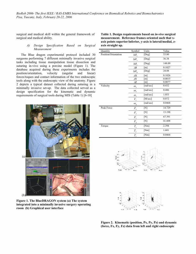
Analyzing this extensive database indicated that 95% of the time the surgical tools operated in a conical range of motion with a vertex angle 60°. We term this the dexterous workspace, DWS (Figure 3a). A measurement taken on a human patient showed that in order to reach the full extent of the abdomen, the tool needed to move 90° in the lateral/medial direction (left to right) and 60° in the superior/inferior directions (foot to head) (Figure 3b). The extended dexterous workspace (EDWS) was defined as a conical range of motion with a vertex angle of 90° and is the workspace required to reach the full extent of the human abdomen without reorientation of the base of the robot.
(a) (b)
Figure 3. Workspace definitions of the surgical robot (a) dexterous workspace –High dexterity region defined by a right circular cone with a vertex angle of 60º and contains 95% of the tool motions based on in-vivo measurements. (b) Extended Dexterous Work Space
B) Experimental Evaluation – Dry/Wet Labs
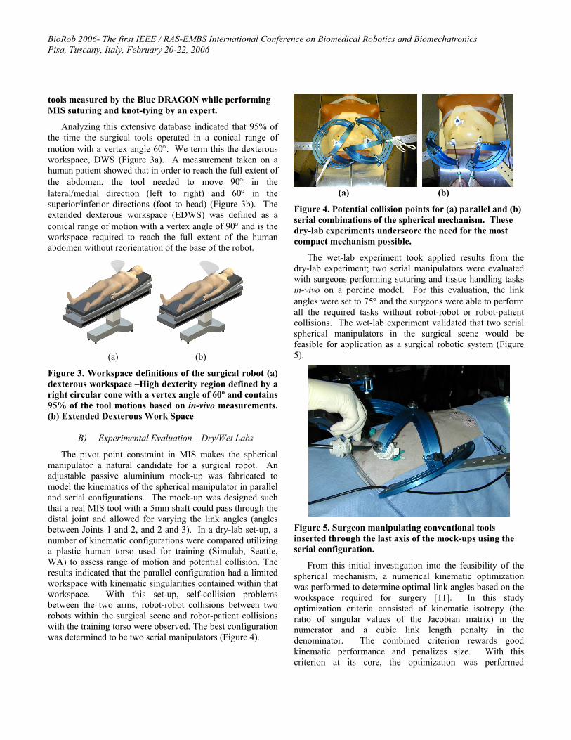
The pivot point constraint in MIS makes the spherical manipulator a natural candidate for a surgical robot. An adjustable passive aluminium mock-up was fabricated to model the kinematics of the spherical manipulator in parallel and serial configurations. The mock-up was designed such that a real MIS tool with a 5mm shaft could pass through the distal joint and allowed for varying the link angles (angles between Joints 1 and 2, and 2 and 3). In a dry-lab set-up, a number of kinematic configurations were compared utilizing a plastic human torso used for training (Simulab, Seattle, WA) to assess range of motion and potential collision. The results indicated that the parallel configuration had a limited workspace with kinematic singularities contained within that workspace. With this set-up, self-collision problems between the two arms, robot-robot collisions between two robots within the surgical scene and robot-patient collisions with the training torso were observed. The best configuration was determined to be two serial manipulators (Figure 4).
(a) (b)
Figure 4. Potential collision points for (a) parallel and (b) serial combinations of the spherical mechanism. These dry-lab experiments underscore the need for the most compact mechanism possible.
The wet-lab experiment took applied results from the dry-lab experiment; two serial manipulators were evaluated with surgeons performing suturing and tissue handling tasks in-vivo on a porcine model. For this evaluation, the link angles were set to 75° and the surgeons were able to perform all the required tasks without robot-robot or robot-patient collisions. The wet-lab experiment validated that two serial spherical manipulators in the surgical scene would be feasible for application as a surgical robotic system (Figure 5).
Figure 5. Surgeon manipulating conventional tools inserted through the last axis of the mock-ups using the serial configuration.
From this initial investigation into the feasibility of the spherical mechanism, a numerical kinematic optimization was performed to determine optimal link angles based on the workspace required for surgery [11]. In this study optimization criteria consisted of kinematic isotropy (the ratio of singular values of the Jacobian matrix) in the numerator and a cubic link length penalty in the denominator. The combined criterion rewards good kinematic performance and penalizes size. With this criterion at its core, the optimization was performed

BioRob 2006- The first IEEE / RAS-EMBS International Conference on Biomedical Robotics and Biomechatronics Pisa, Tuscany, Italy, February 20-22, 2006
comprehensively over the design space with all combinations of each link ranging from 30°-90°. For each design candidate the target workspace was the DWS. Finally, only the designs that could also reach the EDWS were considered. The optimal design of 75° for the first link angle and 60° for the second link angle, was the most compact design that had the best performance over the DWS but could also reach the EDWS. The two link angles along with the in-vivo force and torque data from the Blue Dragon served as the foundation for extensive mechanical design. An important design goal was for the robot to be capable of providing haptic feedback to the surgeon. In order to achieve this goal, the system would have to be lightweight and back-drivable.
III. SURGICAL ROBOT DESIGN
A) Surgical Manipulator
The 7-DOF surgical manipulator used force/torque data collected by the Blue Dragon, the preliminary experimental evaluation and the kinematic optimization as a foundation for its design. The robot is divided into three main subsystems: the static base that holds all seven actuators, the spherical mechanism that positions the tool, and the tool interface. The motion axes of the surgical robot are:
1. Shoulder Joint (rotational) 2. Elbow Joint (rotational) 3. Tool Insertion / Retraction (linear) 4. Tool Roll (rotational) 5. Tool Grasping (rotational) 6. Tool Wrist1 Actuation (rotational) 7. Tool Wrist2 Actuation (rotational)
The first four joint axes intersect at the surgical port location, creating a spherical mechanism that allows for tool manipulation similar to manual laparoscopy. Brushless motors mounted to the base of the micromanipulator actuate all motion axes. The motors are mounted on quick-release plates, which allows for motor removal without the need for disassembling the cable system. Maxon EC-40 motors with 12:1 planetary gearboxes are used for the first three axes, subject to the highest torques. Maxon EC-32 motors are used for the remaining axes. Maxon DES70/10 series amplifiers drive the motors. The selection of DC brushless motors over brushed motors was motivated by a better torque to weight
ratio as well as more efficient heat dissipation due to the fact that the motor’s windings are thermally coupled to its outer case. While the performance benefits of brushless motors are clear, they required more complex and expensive controllers and extensive wiring (14 conductors per motor). The motors of the first three axes have power-off brakes to prevent tool motion in the event of a power failure.
The cable system is comprised of a capstan on each motor, a pretension adjustment pulley, a pulley array to redirect the cables through the links, and attachment to each motion axis. The shoulder axis is terminated on a single partial pulley. The elbow axis has a dual-capstan reduction stage terminating on a partial pulley; the tool insertion / retraction axis has direct terminations of the cables on the tool holder. The tool rotation, grasping and wrist cables are terminated on capstans on the tool interface box.
The cable system transmission ratios are:
1. Shoulder: 7.7:1 motor rotations/joint rotation 2. Elbow: 7.3:1 motor rotations/joint rotation 3. Insertion: 133 radians/meter
Each axis is controlled by two cables, one for motion in each direction, and these two cables are pretensioned against each other. The cables are each terminated at both ends, to prevent any possibility of slipping. The cable system maintains constant pretension on the cables through the entire range of motion; however, there are force and motion couplings between the axes, which must be accommodated for in the control system.
The mechanism’s links are machined from aluminum, and are generally I-section shapes with structural covers. These removable covers allow for access to the cable system, while improving torsional stiffness of the links when they are in place. The links are also offset from the joint axis planes, allowing for a tighter minimum closing angle of the elbow joint. Laser pointers attached to the shoulder and elbow joints allow for visual alignment of the manipulator relative to the surgical port. When the two dots projected on the skin of the patient converge, the manipulator is positioned such that the center of rotation of the surgical manipulator is aligned with the pivot point on the abdominal wall. Each surgical manipulator (Figure 6) has a mass of approximately 15 kg, which includes the motors, gear heads and brakes.

BioRob 2006- The first IEEE / RAS-EMBS International Conference on Biomedical Robotics and Biomechatronics Pisa, Tuscany, Italy, February 20-22, 2006
Figure 6. Surgical Manipulator, CAD and photographic images, Tool Interface, CAD and photographic images
B) Tool Interface
The tool interface allows for quick changing of tools and controls the tool rotation, grasp and wrist axes. A robotic tool changer can release the tool from and attach the tool to the mechanism with a single grasping motion. The tools tips used are modified micro-wrist tools from the Computer Motion Zeus. The tools’ grasp and wrist axes are actuated by pushrods in the tool shaft. High pitch threads are used to convert the rotational motion of the cable system capstans into linear motion of the tool pushrods.
C) Macro-positioner (C-arms)
The 7-DOF surgical manipulator must be positioned such that its center of rotation is coincident with the pivot point of the MIS port and oriented such that the workspace of the robot is aligned with the target anatomy. This is achieved with a 6-DOF positioning system that is supported by a frame structure which is rigidly affixed to the center section of the OR table, allowing it to move with articulations of the bed. The first stage of the positioner is a linear actuator (THK CA) that runs the length of OR table. Next, a passive 2-DOF planar mechanism with a tripod head (Gitzo G1570M Italy), referred to as the ‘C-arm’, positions and orients the surgical manipulator over the patient. Currently a fully actuated C-arm has been designed and future effort will focus on development, fabrication and integration of this element into the complete system.
IV. SOFTWARE AND CONTROLS We developed a USB 2.0 interface board that serves as
the data link between the control software (running on a RTAI Linux computer) and the motor controllers. The USB board includes eight channels of 16bit digital to analog converters for control signal output to each motor controller
and four dual channel 24bit quadrature encoder readers. The board can perform a read/write cycle in 125µs.
Figure 7. BioRobotics Lab, USB2.0 interface device
A) Master Device
When surgeons transitioned from open surgery to MIS, their sense of touch was greatly diminished. Friction between the surgical tool and the seal of the MIS port, as well as the forces exerted on the port by the abdominal wall greatly reduce the surgeons’ ability to feel the tissue they interact with. With the right master interface device, surgical robots present an opportunity for surgeons to regain and potentially enhance their sense of touch in MIS procedures. One of the design goals was to develop a lightweight, low inertia and back-drivable mechanism suitable for enabling force-feedback capabilities in bilateral teleoperation.
Currently, the PHANToM Omni (SenseAble Technologies) is used as the master device. The SenseAble line of PHANToM haptic devices is well established amongst haptics researchers. The cost-effective Omni provides a straightforward software interface that allowed rapid implementation of a surgeon interface device into a master/slave system. It features 3-DOF force-feedback and 6-DOF position/orientation sensors. Additionally, the surgeon station includes a position indexing foot-pedal that
BioRob 2006- The first IEEE / RAS-EMBS International Conference on Biomedical Robotics and Biomechatronics Pisa, Tuscany, Italy, February 20-22, 2006
enables and disables the surgical manipulator, allowing the surgeon to put down the Omni’s stylus without moving the robot.
B) Software and Safety Architecture
The control system and supported electronic hardware were designed to incorporate safety, intelligence, modular design, and flexibility [8,9]. As this is a medical device, the most critical of these aspects is safety. Inherent to a safe system is robustness, reliability, and some level of automatic override. Our system includes safety features such as: a small number of states, Programmable Logic Controller (PLC) state transition control, active enable, brakes, E-STOP, and a surgeon foot pedal. With these features we have a system that we expect will provide a level of predictability, reliability, and robustness sufficient for animal surgery evaluation.
Figure 8. Control system state diagram
A programmable logic controller (PLC - Direct Logic 05) controls the system state transitions based on inputs received from the system and generates outputs to control the RTAI software state, the motor-enable and brakes. PLCs are a well-developed technology used extensively in automation applications. PLC technology is assumed to be inherently reliable, providing built-in safety circuitry that is easy to use. In addition to monitoring the system hardware, the PLC monitors the health of the control software through the use of a watchdog timer. The watchdog timer monitors a square-wave signal from the control software. This square-wave may be considered the “heartbeat” of the control software. In the event of a software failure, the PLC will detect the loss of the heartbeat signal and immediately switch the system into the Emergency Stop state, enabling the brakes and disabling the motors. An array of status LEDs will display the current state of the system.
C) Engineers’ Interface
Robot development is assisted by the Engineering Interface (EI); a low-level interface to the system states and control software. Developers are presented with an intuitive GUI with easy access to the robot’s features. In development stages, the system state - stop, init, run, e-stop- can be set manually with the click of a button. Control commands can be sent to any degree of freedom or the entire
robot; for example, a 40° sine wave can be commanded to the shoulder joint, motor controller number two can output 30% maximum current, or endpoint position can be instructed to move 3cm left. Furthermore, robot states (i.e. motor output, joint position, end-effector position) are output on-screen in real-time, and also logged for later evaluation.
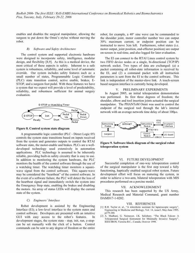
The EI can connect to the RTAI Linux control system by two FIFO device nodes or a single, bi-directional (TCP/IP) network socket. Two types of data are exchanged: (a) a packet containing all robot-state information is received by the EI, and (2) a command packet with all instruction parameters is sent from the EI to the control software. This link is independent of the master-slave link. A touch-screen based surgeon interface is currently being developed.
V. PRELIMINARY EXPERIMENTS In August 2005, an initial teleoperation demonstration
was performed. Its first three degrees of freedom; the shoulder, elbow and tool insertion joints actuated the surgical manipulator. The PHANToM Omni was used to control the endpoint of the surgical tool through the lab’s internal network with an average network time delay of about 100µs.
Figure 9. Software block diagram of the surgical robot teleoperation system
VI. FUTURE DEVELOPMENT Successful completion of one-way teleoperation control
of the surgical manipulator is the first step toward a fully functioning, haptically enabled surgical robot system. Future development effort will focus on maturing the system, in order to achieve a two-arm, bilateral teleoperation with MIS procedures performed on a porcine model.
VII. ACKNOWLEDGMENT This research has been supported by the US Army,
Medical Research and Material Command, grant number DAMD17-1-0202.
VIII. REFERENCES [1] R.H. Taylor et. al., “A telerobotic assistant for laparoscopic surgery”,
Engineering in Medicine and Biology, Vol. 14, issue3, May-June 1995, p279-288.
[2] A. Madhani, G. Neimeyer, J.K. Salisbury. “The Black Falcon: A Teleoperated Surgical Instrument for Minimally Invasive Surgery”. IEEE/IROS, Victoria B.C., Canada, Octover 1998.

BioRob 2006- The first IEEE / RAS-EMBS International Conference on Biomedical Robotics and Biomechatronics Pisa, Tuscany, Italy, February 20-22, 2006
[3] S. Sastry, M. Cohn, and F. Tendick, “Milli-robotics for remote, minimally invasive surgery,” J. Robot Auton. Syst., vol. 21, no.3, p. 305-316, Sept 1997.
[4] T. Li, S. Payandeh, “Design of Spherical Parallel Mechanisms for application to Laparoscopic Surgery,” Robotica, vol. 20, p. 133-138, 2002.
[5] J. Shi, et. al “Preliminary Results on the Design of a Novel Laparoscopic Manipulator” Proceedings of the 11th World Congress in Mechansim and Machine Scirence, April 1-4, 2002.
[6] J. Rosen et. al, “Generalized Approach for Modeling Minimally Invasive Surgery as a Stochastic Process Using a Discrete Markov Model, To be published in IEEE Trans. On BioMedical Engr.
[7] John E. Speich and Jacob Rosen, Medical Robotics, In Encyclopedia of Biomaterials and Biomedical Engineering, Gary Wnek and Gary Bowlin (Editors), pp. 983-993, Marcel Dekker, Inc, NY, 2004
[8] Rosen J., J. D. Brown, M. Barreca, L. Chang, B. Hannaford, M. Sinanan, The Blue DRAGON - A System for Monitoring the Kinematics and the Dynamics of Endoscopic Tools in Minimally Invasive Surgery for Objective Laparoscopic Skill Assessment, Studies in Health Technology and Informatics - Medicine Meets Virtual Reality, Vol. 85, pp.412-418, IOS Press, January 2002.
[9] Rosen J., J. D. Brown, L. Chang, M. Barreca, M. Sinanan, B. Hannaford, The Blue DRAGON - A System for Measuring the Kinematics and the Dynamics of Minimally Invasive Surgical Tools In–Vivo, Proceedings of the 2002 IEEE International Conference on Robotics & Automation, Washington DC, USA, May 11-15, 2002
[10] Rosen J., L. Chang, J. D. Brown, B. Hannaford, M. Sinanan, R. Satava, Minimally Invasive Surgery Task Decomposition - Etymology of Endoscopic Suturing, Studies in Health Technology and Informatics - Medicine Meets Virtual Reality, vol. 94, pp. 295-301, IOS Press, January 2003
[11] M.J.H. Lum et al, Kinematic Optimization of a Spherical Mechanism for a Minimally Inavasive Surgical Robot, IEEE/ICRA, p.829-834, April 2004.
[12] Davies B.L. “The safety of medical robots.” In Proceedings of 29th ISR Conference on Advanced Robotics: Beyond 2000, Birmingham, April, 1998.
[13] Varley, P. “Techniques for Development of Safety-Related Software for Surgical Robots.” IEEE Transactions on Information Technology in Biomedicine, Vol. 3, No. 4, Dec 1999.