Multidisciplinary analysis of CROR propulsion systems: DLR ...
13
ORIGINAL PAPER Multidisciplinary analysis of CROR propulsion systems: DLR activities in the JTI SFWA project A. Stu ¨rmer • R. A. D. Akkermans Received: 8 November 2013 / Revised: 5 March 2014 / Accepted: 6 March 2014 / Published online: 26 March 2014 Ó The Author(s) 2014. This article is published with open access at Springerlink.com Abstract In the frame of the EU 7th Framework Joint Technology Initiative Smart Fixed Wing Aircraft project, the DLR Institute of Aerodynamics and Flow Technology (DLR-AS) is participating as an associated partner in the Airbus-led studies of the Contra-Rotating Open Rotor (CROR) as possible powerplant for future transport air- craft. Due to significant technical challenges in terms of noise emissions, installation effects and certification that still need to be addressed for this novel propulsion system, the numerical activities require the use of sophisticated multidisciplinary analysis tools and approaches covering aerodynamics, aeroacoustics and aeroelastics. In this paper an overview of the DLR-AS work in the project is given, which covers the numerical assessment of a novel noise reduction technology, an initial study of blade aeroelas- ticity as well as some in-depth studies on isolated and installed pusher-configuration CROR engine configura- tions. The first results of a validation of the numerical simulations using experimental test data that is being generated in Airbus-led low-speed wind tunnel tests are also presented. Keywords Contra-rotating open rotor (CROR) Á uRANS Á Aerodynamics Á Aeroacoustics Á Aeroelasticity List of symbols B A Aft rotor blade passing frequency B F Front rotor blade passing frequency C P Power coefficient, C P = P/(qn 3 D 5 ) C F Total force coefficient, C F = (C T 2 ? C Y 2 ? C Z 2 ) 0.5 C L Lift coefficient, C L = F z /(qS) C T,Y,Z Thrust, lateral and lift coefficient, C T,Y,Z = F x,y,z /(qn 2 D 4 ) D Front rotor diameter f Frequency F x,y,z Forces in Cartesian coordinate system M Mach number n Rotor rotational frequency P Power q Dynamic pressure, q = 0.5qV 0 2 r Radial position R Rotor radius S Reference area V 0 Freestream velocity x,y,z Cartesian coordinate system positions Greek symbols a Angle of attack W Azimuth angle q Density h Polar angle Abbreviations CFD Computational fluid dynamics CROR Contra-rotating open rotor FW–H Ffowcs Williams–Hawkings SPL Sound pressure level TEB Trailing edge blowing uRANS Unsteady Reynolds averaged Navier–Stokes This paper is based on a presentation at the German Aerospace Congress, September 10–12, 2013, Stuttgart, Germany. A. Stu ¨rmer (&) Á R. A. D. Akkermans DLR Institut fu ¨r Aerodynamik und Stro ¨mungstechnik, Lilienthalplatz 7, 38108 Braunschweig, Germany e-mail: [email protected] 123 CEAS Aeronaut J (2014) 5:265–277 DOI 10.1007/s13272-014-0105-4
Transcript of Multidisciplinary analysis of CROR propulsion systems: DLR ...

ORIGINAL PAPER
Multidisciplinary analysis of CROR propulsion systems:DLR activities in the JTI SFWA project
A. Sturmer • R. A. D. Akkermans
Received: 8 November 2013 / Revised: 5 March 2014 / Accepted: 6 March 2014 / Published online: 26 March 2014
� The Author(s) 2014. This article is published with open access at Springerlink.com
Abstract In the frame of the EU 7th Framework Joint
Technology Initiative Smart Fixed Wing Aircraft project,
the DLR Institute of Aerodynamics and Flow Technology
(DLR-AS) is participating as an associated partner in the
Airbus-led studies of the Contra-Rotating Open Rotor
(CROR) as possible powerplant for future transport air-
craft. Due to significant technical challenges in terms of
noise emissions, installation effects and certification that
still need to be addressed for this novel propulsion system,
the numerical activities require the use of sophisticated
multidisciplinary analysis tools and approaches covering
aerodynamics, aeroacoustics and aeroelastics. In this paper
an overview of the DLR-AS work in the project is given,
which covers the numerical assessment of a novel noise
reduction technology, an initial study of blade aeroelas-
ticity as well as some in-depth studies on isolated and
installed pusher-configuration CROR engine configura-
tions. The first results of a validation of the numerical
simulations using experimental test data that is being
generated in Airbus-led low-speed wind tunnel tests are
also presented.
Keywords Contra-rotating open rotor (CROR) �uRANS � Aerodynamics � Aeroacoustics � Aeroelasticity
List of symbols
BA Aft rotor blade passing frequency
BF Front rotor blade passing frequency
CP Power coefficient, CP = P/(qn3D5)
CF Total force coefficient,
CF = (CT2 ? CY
2 ? CZ2)0.5
CL Lift coefficient, CL = Fz/(qS)
CT,Y,Z Thrust, lateral and lift coefficient,
CT,Y,Z = Fx,y,z/(qn2D4)
D Front rotor diameter
f Frequency
Fx,y,z Forces in Cartesian coordinate system
M Mach number
n Rotor rotational frequency
P Power
q Dynamic pressure, q = 0.5qV02
r Radial position
R Rotor radius
S Reference area
V0 Freestream velocity
x,y,z Cartesian coordinate system positions
Greek symbols
a Angle of attack
W Azimuth angle
q Density
h Polar angle
Abbreviations
CFD Computational fluid dynamics
CROR Contra-rotating open rotor
FW–H Ffowcs Williams–Hawkings
SPL Sound pressure level
TEB Trailing edge blowing
uRANS Unsteady Reynolds averaged Navier–Stokes
This paper is based on a presentation at the German Aerospace
Congress, September 10–12, 2013, Stuttgart, Germany.
A. Sturmer (&) � R. A. D. Akkermans
DLR Institut fur Aerodynamik und Stromungstechnik,
Lilienthalplatz 7, 38108 Braunschweig, Germany
e-mail: [email protected]
123
CEAS Aeronaut J (2014) 5:265–277
DOI 10.1007/s13272-014-0105-4

1 Introduction
In the frame of the 7th Framework EU Joint Technology
Initiative Smart Fixed Wing Aircraft project (JTI SFWA)
[1], the DLR Institute of Aerodynamics and Flow Tech-
nology (DLR-AS) is contributing to a comprehensive
investigation into the feasibility of Contra-Rotating Open
Rotor (CROR) propulsion systems for future single-aisle
transport aircraft. In order to improve the understanding of
the complex flow physics as well as to advance the tech-
nical maturity of employing this type of engine as a pow-
erplant in the context of stringent efficiency and
certification requirements relating to performance, pollu-
tant and noise emissions, DLR is employing a multidisci-
plinary numerical approach based on high-fidelity tools
[2, 3]. While the high bypass ratio of CROR engines results
in a superior propulsive efficiency, their integration on an
aircraft requires careful consideration of complex engine–
airframe interactions impacting performance, aeroelastics
and aeroacoustics [4, 5]. The focus configuration across all
activities is the generic Airbus AI-PX7 pusher CROR
configuration, a 11 9 9-bladed design featuring an aft rotor
diameter reduction of 10 % with respect to the front rotor
[6]. This propulsion system is studied in three principal
variants in various tasks of the project:
• A full-scale isolated CROR configuration, i.e. with an
axisymmetric nacelle for the innovative blade and
pylon design studies.
• A 1/5th scale wind-tunnel model, called Z49, which is
being tested as an isolated CROR at cruise conditions in
the ONERA S1 wind tunnel and will also be investi-
gated at low-speed conditions in the DNW-LLF tunnel
in both isolated and semi-installed (i.e. including a
pylon) configurations.
• A 1/7th scale wind-tunnel model, called Z08, designed
for a recently completed series of tests at low-speed
conditions in the DNW-LLF wind tunnel in configura-
tions ranging from isolated to semi-installed and fully-
installed on the empennage of a representative T-tail
aircraft configuration.
In the first discussion of results in this paper, the
activities by DLR-AS in support of a task analyzing some
novel technologies aimed at addressing CROR noise
emissions on a fundamental level through an investigation
of the general efficacy of employing front rotor trailing
edge blowing for the reduction of CROR interaction tone
noise emissions will be discussed. Another important field
of work in the project, which could have a potentially
significant impact on CROR performance and noise emis-
sions, is the aeroelasticity of the rotor blades. In support of
the preparation of the wind tunnel testing, DLR contributed
to the definition of the blade jig shape utilizing a coupled
simulation based on CFD and computational structural
mechanics (CSM) tools, a step necessary to ensure the
flexible blades operate in their design shape during the
experimental test campaign.
Finally, drawing on wide-ranging experimental test
campaigns using several CROR engine simulators at vari-
ous scales, a major focus of the JTI SFWA activities is the
robust validation of the unsteady computational fluid
dynamics (CFD) simulations employing the DLR TAU-
Code and the coupled aeroacoustic analysis using the DLR
APSIM?-Code [2, 3]. For low-speed conditions, the recent
test of the Airbus-designed 1/7th-scale Z08-CROR provide
a broad scope of data to assess the numerical methods’
ability to properly predict the aerodynamic performance as
well as the noise emissions of CROR engines as influenced
by their integration on an airframe and the specific
requirements placed on the numerical tools and
approaches.
2 Numerical approach
With the issue of noise being a primary concern for the
realization of a viable CROR propulsion system, most
simulations performed by DLR-AS within the scope of the
JTI SFWA project are typically coupled CFD–CAA sim-
ulations utilizing the DLR TAU-Code for the uRANS
aerodynamic analysis and the DLR FWH-Code APSIM?
for the subsequent noise analysis.
2.1 DLR TAU-Code CFD simulations
The DLR TAU-Code is an unstructured finite-volume
vertex-based CFD solver. For the simulation described
here, spatial discretization of the convective fluxes is done
using a second order central differencing scheme with
scalar dissipation while the viscous fluxes are discretized
with central differences. Turbulence is modeled with the
1-equation Spalart–Allmaras model [7]. The dual time
approach is used in the DLR TAU-code to compute
unsteady flows [8], while the relative motion of the rotors is
handled using the code’s Chimera capability as well as the
implemented motion libraries [9].
2.1.1 Mesh generation
The typical approach for the mesh generation process for
the CROR configurations studied in the JTI SFWA project
is to use three Chimera blocks, which are generated using
both the CentaurSoft Centaur and the ANSYS ICEM CFD
mesh generation softwares. The nacelle mesh block, which
has farfield boundaries typically located at a distance of 20
times the front rotor diameter from the engine axis and
266 A. Sturmer, R. A. D. Akkermans
123

front rotor center, is a hybrid/unstructured mesh, as can be
seen in Fig. 1. Both the front and aft rotor meshes on the
other hand are block-structured grids. In addition to
ensuring an adequate resolution of boundary layers
(including the laminar sublayer) on all surfaces of the
CROR, a particular focus of the mesh generation was the
requirement to adequately resolve the aeroacoustic pres-
sures in the rotor mesh blocks during the CFD simulation
in order to use the nacelle Chimera boundary as the input
permeable surface for the APSIM? analysis. Therefore, the
mesh density of the front and aft rotor grids was dictated by
the need to resolve all relevant sound pressures typically
through the 5th harmonic of the front rotor blade passing
frequency.
Typical mesh sizes for the configuration discussed in
this paper are around 60 million nodes for an isolated
CROR configuration, while the added modeling of the
pylon leads to grids of around 70 million nodes.
2.1.2 uRANS simulations
The aerodynamic simulations follow an approach that has
been successfully applied in a number of CROR simula-
tions performed at DLR-AS in recent years. In a first step, a
steady-state start-up simulation without any rotor motion is
done to initialize the flowfield before the unsteady simu-
lations are started. A successive refinement of the physical
time-step size is done in the course of the simulation to
speed up the achievement of a periodic state in the flow.
For the final period, i.e. the final rotation of the rotors,
typically a time-step size resulting in a 0.5� rotation of the
rotors is set. For isolated CROR configurations a converged
periodic state is usually achieved after 5 rotor revolutions,
while for cases including a pylon the achievement of
periodic forces on the pylon normally requires computing
12 full periods. With the simulations run using between
360 and 720 CPUs of DLRs C2A2S2E cluster, these sim-
ulations require between 2 and 4 weeks of runtime
respectively. Results of the final rotation are then post-
processed for the aerodynamic analysis as well as for use in
the aeroacoustic analysis.
2.2 DLR APSIM?-Code CAA simulations
The Aeroacoustic Prediction System based on Integral
Method (APSIM?) was developed at the DLR Institute of
Aerodynamics and Flow Technology for the prediction of
rotor or propeller noise radiated in the free farfield. As
mentioned, in the current applications the unsteady CFD
data on the Chimera boundary surfaces surrounding the
propellers is used for an aeroacoustic analysis based on the
permeable surface Ffowcs-Williams/Hawkings (FWH)
approach [10–12]. Shown as the translucent cylindrical
surface in Fig. 2, this choice was made out of practical
considerations, since this boundary represents an already
existing closed surface which encloses the relevant noise
sources of the geometry, i.e. the rotors. The noise contri-
bution of the nacelle, which lies outside of the permeable
surface, is not considered in the present APSIM? com-
putations. The calculations, which for the present JTI
SFWA cases are performed in the time domain, deliver
pressure amplitude and phase information at any desired
observer location, which is further analyzed to derive
acoustic spectrum data. For the overall sound pressure level
Fig. 1 Representative Chimera blocking strategy for the CFD
simulations shown for the isolated AI-PX7 CRORFig. 2 TAU-APSIM? coupling process and setup
Smart fixed wing aircraft project 267
123

(OASPL), usually all frequencies up to five times the front
rotor blade passing frequency (f = 5BF) are considered. In
this paper, unless otherwise noted, the CAA results are
shown as farfield polar directivities for a virtual ground
microphone array sketched in Fig. 2, which lies parallel to
the engine axis at a distance of 11 front rotor diameters
below the CROR configuration.
3 Front rotor trailing edge blowing
In the frame of the Airbus-led task 2.2.2.1 ‘‘Design of
Innovative CROR Blade and Pylon’’, DLR-AS is investi-
gating the general efficacy of applying front rotor trailing
edge blowing (TEB) for the reduction of interaction tone
noise emissions of CROR propulsion systems [13]. For this
study, each blade of the AI-PX7 CROR’s front rotor was
modified to include a slot just upstream of the trailing edge
on the blade suction side for much of the blade span. This
slot is laid out as a backward facing step in order to
facilitate an air injection tangential to the surface of the
blade suction side. The investigations are focused on the
isolated CROR at typical low-speed M = 0.23 take-off
conditions, for which interaction tone noise is a concern for
the flyover noise certification [4].
Figure 3 compares the front blade wakes at an axial
position of x/D = 0.08 downstream of the front rotor in
terms of the instantaneous dynamic pressure profiles at a
radial position of 80 % span of the front blade. The
injection of air near the trailing edge along the front blade
span serves to significantly reduce the wake deficit. In this
initial assessment, the primary aim was to demonstrate the
potential of front rotor blowing for CROR interaction tone
noise emission reductions. Thus, a wake filling was tar-
geted for the entire aft blade span, resulting in a relatively
large air massflow.
The success of this reduction in front blade wake
strength can be seen in the reduced local loading fluctua-
tions at a corresponding spanwise position of the aft blade,
as plotted in Fig. 4. In comparison to the baseline case, the
blowing configuration shows a significant reduction in the
oscillations of the local blade loading coefficient. For this
study, the baseline and the blowing case were investigated
at identical blade pitch settings of the front and aft rotor.
This was found to be acceptable as only a marginal impact
on the CROR performance was found. The overall thrust is
reduced by a mere 0.175 %. Figure 4 shows that the mean
value of the aft blade loading is reduced for the active flow
control case in comparison with the reference configura-
tion. For the complete aft rotor, the reduction in average
thrust is 2.215 %, while the blowing case shows an
increase in front rotor mean thrust of 1.276 %.
Figure 5 shows the tonal decomposition of the noise
emissions for a farfield microphone located in the front
rotor plane. The black bars represent the baseline case,
while the results of the active flow control case are shown
in gray. Very little impact of the TEB application is seen in
the front and aft rotor tones (‘‘F’’ and ‘‘A’’), which supports
the previously stated observation that the slight difference
in the mean front and aft rotor thrust levels between the two
cases is negligible. On the other hand, notable reductions
can be seen in most interaction tones.
Despite this apparent success in wake alleviation, the
farfield ground noise directivity comparison in Fig. 6
reveals only a small peak noise reduction in the vicinity of
the rotors, while a significant noise penalty is in fact found
Fig. 3 Impact of TEB on front rotor blade wakes
Fig. 4 Aft blade local loading oscillation reduction through applica-
tion of front rotor trailing edge blowing
268 A. Sturmer, R. A. D. Akkermans
123

in the upstream directions. As discussed in detail in [13],
the primary reason for this is traceable to the only very
moderate cropping of the aft rotor diameter of this partic-
ular CROR configuration. Thus front blade tip vortices still
impinge on the aft blades and are in fact the primary source
of interaction tone noise—which cannot be ameliorated
through the reduction of the blade wakes. In order to fur-
ther demonstrate the efficacy of front rotor TEB, a follow-
up to this study was done, which utilized a generic CROR
configuration developed by DLR-AS, which is presented in
detail in another publication [14]. This CROR features an
aft rotor crop of 15 % versus the front rotor and thus fully
avoids the interaction with the front blade tip vortices. The
use of front rotor TEB in this case did in fact lead to a very
pronounced reduction in noise emissions (2.5 dBA peak
noise and up to 5 dBA in the up- and downstream direc-
tion), substantiating the general efficacy of this flow control
technology for interaction tone noise emissions for CROR
applications.
4 CROR blade aeroelastics
Task 2.2.2.2, which is led by NLR, is focused on the
analysis of the impact of blade deformation on the aero-
dynamic and aeroacoustic performance of the CROR.
Aeroelasticity is especially important for CROR blades,
since they tend to be thin for good performance at high
Mach numbers and feature large sweep and twist, which
leads to a coupling of the blade deformation in bend and
twist. A complex combination of aerodynamic, centrifugal
and Coriolis forces on the blades of a rotor needs to be
properly accounted for in a multidisciplinary analysis of
CROR propulsion systems. Aerodynamic and particularly
the centrifugal forces due to rotor rotation have a strong
impact on blade stiffness, notably impacting the structural
eigenfrequencies and mode shapes, while the Coriolis
forces have a damping effect. Initially this task was scoped
to guide the design of the model scale rotors to ensure the
blade shapes matched the design shapes under wind tunnel
test operating conditions, in particular for the high-speed
tests planned to be performed in the ONERA S1 tunnel.
Thus numerous partners employed numerical methods to
derive the so-called cold- or jig-shape of the front and aft
rotor blades from the target shapes envisioned by Airbus
for the AI-PX7 CROR design. Utilizing a finite element
model delivered by task partner IBK, which was guided by
the carbon fiber ply layup planned by NLR for the blade
manufacturing, DLR-AS employed the non-linear hot-to-
cold analysis functionality provided by the SOL106 solver
in the commercial NASTRAN FE-modeling software to
compute the expected deflections of the blades under load.
In addition to the pre-stressing effect of the centrifugal
loading resulting from the high rotational speeds of the
rotors at model scale, the mean blade pressure distributions
are a necessary input to this approach. The latter was
obtained through an averaging of the blade surface pres-
sures from a uRANS simulation of the CROR at the
expected operating conditions in the wind tunnel test, while
the former is specified using the RLOAD card of NA-
STRAN. As shown for the example of an aft blade in
Fig. 7, the deflections at the tip are small but measureable.
Of note is the slight difference in the displacements of the
blade at the tip leading and trailing edges, indicating a
small amount of blade torsion under loads, which is
important to account for to obtain proper aerodynamic
performance in the wind tunnel test.
Fig. 5 Impact of front rotor trailing edge blowing on tonal noise
spectra in the front rotor plane
Fig. 6 Impact of TEB on ground noise directivities
Smart fixed wing aircraft project 269
123

Figure 8 shows the first four mode shapes for the blade
of a front rotor as computed in the NASTRAN analysis. In
order to validate the FE-models dynamic properties, a
comparison of the computed eigenfrequencies for a non-
rotating blade with results of a ‘‘ping test’’ analysis of the
actual manufactured blade is shown in Table 1. As listed,
the first three eigenfrequencies are within 1 % of the test
results, with a larger deviation of 2.2 % found for the
fourth eigenfrequency. A possible reason for the latter
deviation in an otherwise very good correlation is that the
ply layup of the final manufactured blade was slightly
altered versus that used in the FE-model.
Figure 9 shows the Campbell diagram for the investi-
gated 1/5th scale front rotor blade, which plots the
numerically computed development of the blade’s eigen-
frequencies with the rotational speed of the propeller.
Clearly evident is the stiffening effect of the centrifugal
loading on the blade, as the eigenfrequencies are seen to
increase slightly as the propeller rotational speeds grow.
5 Pre-test installation effects study
In task 2.2.2.6 of the JTI SFWA project, which is led by
Airbus, investigations are focused on the AI-PX7 CROR
configuration at 1/5th scale. The associated wind tunnel
model, termed Z49 by Airbus and ONERA, will be tested
in isolated and semi-installed configurations at low-speed
conditions in the DNW-LLF and as an isolated CROR at
high-speed conditions in the ONERA S1 wind tunnel. Due
to the relatively large scale, the models are heavily
instrumented and will provide a broad range of steady and
unsteady pressure data on the blades, the nacelle and pylon
along with six-component rotating shaft balance data for
each rotor. With the high-speed tests just recently per-
formed in the summer of 2013, the project partners have
been conducting pre-test, or ‘‘blind’’, CFD–CAA simula-
tions with the aim of cross-plotting the results from the
various methods and approaches used. For DLR-AS,
another main focus was the study of the installation effect
caused by the presence of the pylon. In general, despite
some notable differences in the flow solvers as well as the
methodology used by the various partners, the aerodynamic
performance predictions so far fall within a scatter of
around 3 % in most cases. For the reference low-speed
flight conditions at a speed of M = 0.23, DLR-AS studies
were focused on the installation effect due to an angle of
attack as well as the interaction with the pylon. For the
latter case, Fig. 10 shows a visualization of the vortical
flow structures. In addition to the pronounced rotor–rotor
interactions due to blade wake and tip vortices as well as
blade potential flowfields, the pylon wake introduces an
additional strong source of unsteady loading for the rotors
during its passage behind the pylon.
Fig. 7 1/5th scale aft blade tip deflection prediction
1st Bending 2nd Bending 1st Torsion 3rd Bending
Fig. 8 1/5th scale front blade mode shapes
Table 1 Eigenfrequency deviations in the numerical and experi-
mental results for the 1/5th scale front blade
Mode 1 Mode 2 Mode 3 Mode 4
Df(FEM-EXP) -0.6 % -0.4 % -0.7 % -2.2 %
Fig. 9 1/5th scale front blade Campbell diagram
270 A. Sturmer, R. A. D. Akkermans
123

Figure 11 shows a comparison of the front and aft blade
total force coefficient time history for the three low-speed
cases studied so far. In the figure all front and aft blade
values are normalized to the average value of the front and
aft blade of the isolated CROR at axial flow conditions,
respectively. For the isolated CROR at axial flow condi-
tions the blade loadings show periodic oscillations around a
constant mean value during one full rotor rotation. The
unsteady loading is a result of the rotor–rotor interactions,
with aft blades affected by front rotor blade wakes and tip
vortices, while the front rotor is influenced by the aft blades
potential flow.
This is evident in the spectral analysis of the unsteady
loading, plotted in Fig. 12, where the dominant frequencies
of a front blades periodic fluctuation are the even number
higher harmonics of the aft blades blade passing frequen-
cies. For an aft blade, the unsteady component of the
loading occurs at the even number higher harmonics of the
front blade passing frequency. For the fundamental fre-
quency, the unsteady loading for an aft blade is larger than
that of a front blade, indicating that blade wake and tip
vortex impingement is the more substantial cause of rotor–
rotor interactions than is the potential flow effect.
When the isolated CROR is subject to an angle of attack
of a = 4�, the blades exhibit a sinusoidal loading cycle in
addition to the rotor–rotor interaction fluctuations. For a
front rotor’s blade, the largest loading occurs on the
downward sweep at an azimuthal position of around
W = 110�, while the magnitude drops below the values
found for the isolated CROR at axial flow on the upward
rotation, with a minimum at around W = 290�. Obviously,
the spectral analysis now shows the dominant unsteady
loading at the rotor rotational speed, while only a marginal
impact on the rotor–rotor interaction driven unsteady
loading is seen.
The pylon wake impingement on the rotors leads to an
abrupt increase in blade loadings, which occurs at an azi-
muthal angle of around W = 90� for a front and, to a lesser
degree, at around W = 270� for an aft blade. In the Fourier
analysis, the pylon effect is found to cause a richer fre-
quency content of unsteady loading with only small
changes in fluctuation amplitude versus the previous case
at the dominant frequencies of f = n, f = 2BA and
f = 2BF.
Fig. 10 Semi-installed Z49-CROR vortical flow structures
Fig. 11 Blade total force coefficient time history, normalized to
mean values of isolated axial flow case
Fig. 12 Spectral analysis of unsteady blade total loading
Smart fixed wing aircraft project 271
123

Quite importantly, the rotor flowfield also has an
upstream impact on the pylon. Figure 13 shows a contour
plot of the time history of a pylon section pressure distri-
bution at a spanwise position corresponding to a location at
r/R = 0.75 of the front rotor diameter. Dominant unsteady
pressure fluctuations are evident at the trailing edge, which
are seen to propagate all the way to the leading edge of the
pylon. This strong unsteady component in the rotor-inter-
action driven pylon flow is evident in the periodic lift
coefficient fluctuations during one full rotor rotation plot-
ted in Fig. 14. The spectral analysis of this unsteady
loading, shown in the figure inset, occurs primarily at a
frequency associated with each of the front rotor blade’s
passage, i.e. the front rotor blade passing frequency. Only a
very marginal direct interaction of the aft rotor on the
pylon is detectable in the very small peak occurring at the
aft rotors blade passing frequency. A small contribution to
the unsteady loading is also seen at the first order inter-
action frequency as well as at a frequency corresponding to
twice the shaft order. Since the latter corresponds exactly
to the difference in the number of blades in the front and aft
rotor, these two effects can be attributed to the impact of
the rotor–rotor interactions. Since the individual blade
loadings show a dependence on the interactions with the
blades of the respective other rotor, as was discussed for
Fig. 11, their upstream influence on the pylon reflect this
through the unsteady pylon lift fluctuations at the two
frequencies noted.
In addition to this unsteady effect of the rotors on the
pylon, a comparison of the mean power-on lift coefficient
with the pylon lift coefficient taken from a simulation
omitting the rotors, shows, that due to the acceleration of
the flow into the front rotor, the magnitude of the pylon lift
coefficient is notably increased. Therefore, the rotors
influence on the pylon lead to important steady and
unsteady installation effects.
Figure 15 plots a comparison of the ground noise di-
rectivities as computed with APSIM? for a microphone
array located at constant distance of around 11 rotor
diameters from the engine axis. The directivities are split
into tones associated to the front and aft rotors as well as
those occurring at the interaction frequencies. The isolated
CROR at axial flow conditions shows the focused direc-
tivity of the rotor tones, which radiate primarily in the
direct vicinity of the plane of rotation of the rotors. In
contrast, the interaction tones radiate strongly in the up-
and downstream directions, leading to the CROR-charac-
teristic flat overall noise directivity in the farfield. For the
isolated CROR at angle of attack, increases of around 2 dB
in ground noise levels are found for both the front and aft
rotor tones versus the axial flow case. This correlates with
the higher blade loadings during the blades downward
rotation, as was discussed in the analysis relating to
Fig. 11. A smaller increase in the interaction tone levels is
seen, which is in agreement with the relatively small
impact on the magnitude of the unsteady rotor–rotor
interaction found for the blade loadings in Figs. 11, 12 as
the angle of attack is increased. The pylon has a more
pronounced influence on the ground noise directivities,
leading to increases in both front and aft rotor tones over
and beyond what was seen for the angle of attack effect
alone. Furthermore, the additional unsteady loading
induced by the impingement of the pylon wake on the front
blades leads to a large increase in the up- and downstream
radiation of the front rotor associated tones. Since the
Fig. 13 Pylon pressure distribution time-history Fig. 14 Impact of the rotors on pylon lift development for the case at
an angle of attack of a = 4�
272 A. Sturmer, R. A. D. Akkermans
123

pylon wake is already significantly dissipated in its inter-
action with the front rotor blades, its only minor effect on
the aft rotor blades explains why aft rotor tone radiation in
the up- and downstream direction are much less increased
than the front rotor tones. Finally, the interaction tone
ground noise directivity again shows only very small dif-
ference due to the installation effect of the pylon. This front
rotor noise increase due to the pylon impact is potentially a
big drawback for a pusher configuration CROR propulsion
system. This is because it has a very negative impact in the
fly-over noise certification scenario, where the prolonged
exposure of a given observer on the ground to high levels
of the noise is penalized in Effective Perceived Noise Level
(EPNL) metric. Therefore some analysis of means to
reduce the effect of the pylon wake impingement on the
rotors have been undertaken in recent years, both inside the
JTI SFWA project as well as independently [15].
In advance of the experimental results becoming avail-
able for the validation work, DLR has focused on some
studies to further enhance the fidelity and accuracy of the
numerical simulations. One possible shortcoming that has
been identified relates to the process chain that draws on
acoustically resolved CFD data only in the immediate
nearfield of the rotors as input to the APSIM? permeable
surface CAA analysis. While this approach has many
advantages and is generally found to be a preferred setup
for a coupled CFD–CAA investigation, there are several
reasons why a possible adaptation of this process chain
might be necessary. Firstly, an analysis using the FW-H
equation draws on the hypothesis that the propagation of
the acoustic waves away from the permeable surface into
the farfield occurs in a uniform flow. However, this is not
strictly true even for an isolated CROR configuration, as
there are clear flow non-uniformities in the up- and
particularly in the downstream direction. These are
expected to have some possibly important effects on the
propagation of the sound waves away from the rotor in the
nearfield. Another aspect is the limited extent of the Chi-
mera surface used for the coupling between the TAU- and
APSIM-codes. While it enclosed the rotors as the dominant
noise sources and also inherently accounts for quadrupole
contributions, it possibly neglects some relevant installa-
tion effects. These comprise aeroacoustic installation
effects, such as reflections on the nacelle or pylon, as well
as some additional potentially important noise sources. One
such noise source could be the pylon itself, which, as
shown in Fig. 13, clearly exhibits some strong unsteady
pressure fluctuations. To study some of these aspects, a
mesh refinement study was performed, which aimed to
resolve acoustic wave propagation in the nearfield of the
isolated CRORs nacelle in a region extending 1.5 rotor
diameters in the up- and downstream as well as in the radial
direction. This required a significant refinement of the
nearfield nacelle mesh to be able to resolve acoustic pres-
sures up to a frequency of f = 3BF in the CFD simulation.
A comparative uRANS simulation using two meshes was
done for the isolated Z49 configuration at typical low-
speed take-of conditions at an angle of attack of a = 4�,
where a baseline mesh with 94e6 nodes was compared with
the aeroacoustically adapted mesh with 150e6 nodes. Fig-
ure 16 plots the results of an evaluation of the noise
emissions at a radial distance of r/R = 3 from the engine
axis below the CROR as extracted directly from the CFD
simulation results. For comparison, results of an APSIM?-
evaluation based on the nacelle Chimera porous surface
input data are included, as computed for the same virtual
microphone positions. As the rotor meshes were identical
for both the baseline and the refined mesh, only one FW-H
result is shown. For all three cases, the figure shows di-
rectivities for the overall sound pressure level (OASPL)
based on all tones up to and including the third harmonic of
the front rotor blade passing frequency as well as the
directivity of the first interaction tone.
The polar directivity shows the expected benefit of the
refined mesh to capture higher frequency tones versus the
baseline mesh in the upstream and radial directions in the
direct evaluation of noise in the CFD results. This is
manifested through higher overall sound pressure levels of
around 1 dB in these regions when comparing the two CFD
results and generally similar differences for the plotted
interaction tone levels. The largest discrepancy between
both the two CFD-based and the FW-H results is found in
the downstream region. In comparison with the latter data,
both CFD-based evaluations show significant differences in
the directivity characteristics as well as localized increased
noise emissions of around 4 dB. The plotted interaction
tone results indicate a more complex directivity pattern
Fig. 15 Installation effect impact on tone ground directivity
Smart fixed wing aircraft project 273
123

versus the porous surface results, which thus can be linked
clearly with the impact of the strong non-uniform flow in
the rotor wake on the noise propagation. Furthermore,
comparing the two CFD-based evaluations shows that the
better high-frequency resolution capability of the refined
mesh as well as the better resolution of the complex
aerodynamic flowfield results in additional small lobes in
the most downstream portions of the directivities plotted in
the figure [16]. The CFD simulations with such large
meshes are naturally quite expensive, but the upcoming
validation activities will be able to show if this approach is
worth the extra computational cost to better match exper-
imental data.
6 Validation of CFD–CAA analysis
The final major CROR-related work package in the JTI
SFWA project, the DLR-led task 2.2.4.5 ‘‘Numerical
Assessment of the Installed CROR Configuration’’, has the
aim of furthering the understanding as well as the analysis
capabilities of the aerodynamic and aeroacoustic installa-
tion effects at low-speed flight conditions. Aeroacoustics
are the primary focus area, as noise emissions at take-off
conditions are the dominant concern for the certification of
a CROR-powered aircraft. The main input to this task is a
series of wind-tunnel tests of the Z08 1/7th scale AI-PX7-
based pusher configuration CROR in the DNW-LLF
facility. These experimental studies, initiated in 2012 and
completed in the first half of 2013, encompassed perfor-
mance and noise measurements of isolated, semi-installed
as well as fully installed CROR configurations. While the
reduced scale versus the Z49-model studied in task 2.2.2.6
constrained the instrumentation of the models slightly, the
resulting database included results from a significant
number of steady and unsteady pressure sensors on the
blades, nacelle, pylon and aircraft, 6-component rotating
shaft balance data for both rotors of the CROR as well as a
wealth of microphone measurements.
The numerical analysis described here, which are
focused directly on the validation of the CFD and CAA
tools and approaches, are done for an initial test case of the
isolated CROR configuration at axial flow conditions,
matching exactly a test point in the wind tunnel tests.
In order to determine the best coupling strategy between
the CFD and CAA simulations, the numerical approach
described in Sect. 2 has been adapted slightly in order to
test both the feasibility and the benefit of an extension of
the resolution of acoustic waves in the CROR nearfield.
While rotor meshes are generated in much the same man-
ner as described previously, an additional Chimera block is
used for the relevant CROR nearfield region, as shown in
Fig. 17. For the nacelle, a block-structured mesh, adapted
in its cell-sizes to resolve and propagate acoustic pressures
corresponding to the 3rd front rotor blade passing fre-
quency, are now used. A major focus of the mesh gener-
ation is a detailed study of the resolution requirements in
the rotor–rotor interface region, as shown in Fig. 18. To
ensure blade wakes from the front rotor are transferred with
minimal losses across the Chimera boundary into the aft
rotor block, the interface region ensures a 1:1 azimuthal
matching of the cells on either side. For this particular case
a total of 1,584 cells are used for the full analysis. In the
simulations, a time-step study is performed, which suc-
cessively reduces the size of the physical time step in the
uRANS analysis up to a level that corresponds to a one-cell
motion along the azimuth. Another important aspect of the
present studies is a mesh refinement study for the isolated
Z08-CROR configuration. While in most cases aeroacou-
stic requirements dictate the size of the mesh, for many
purely aerodynamic-focused analyses a much less refined
mesh is often sufficient.
Table 2 gives an overview of the mesh family that was
created. The baseline mesh, sized for the requirements of
the aeroacoustic analysis, is coarsened in all directions by a
factor of 1.33 to obtain a medium-sized mesh and again to
result in a coarse mesh. While the latter two no longer
ensure an adequate resolution of acoustic waves in the
desired high frequency range of interest in the CFD sim-
ulations, the expectation is that they will yield results in
terms of CROR performance that are possibly fully suffi-
cient for most aerodynamic aspects of interest and of
course will also enable a robust mesh convergence study to
be done. The CFD studies are done initially for the isolated
Fig. 16 Mesh refinement impact on uRANS-CFD resolved nearfield
noise emission directivities for the isolated CROR at an angle of
attack of a = 4�
274 A. Sturmer, R. A. D. Akkermans
123

CROR configuration, and replicate a wind-tunnel test point
in terms of the take-off case flight conditions of M = 0.2
and axial flow conditions as well as in the CROR operating
point in terms of blade pitch and rotor rotational speed.
Figure 19 shows two instantaneous results of the med-
ium mesh simulations, which show the impact of the time
step size on the transfer of blade wakes through the Chi-
mera interface on a circumferential surface at 50 % of the
front rotor radius. In the left half of the figure vorticity
contours are shown for the simulation in which a time step
size is used which results in a relative motion of two cells
at the rotor–rotor Chimera interface. When compared with
the result plotted in the right half of the figure, where the
time step is reduced by half, resulting in a one cell relative
motion a qualitative improvement in the wake transfer is
evident. This is most noticeable in the more rapid decay of
the front blade wakes as they interact with the aft blades for
the case of the larger time step.
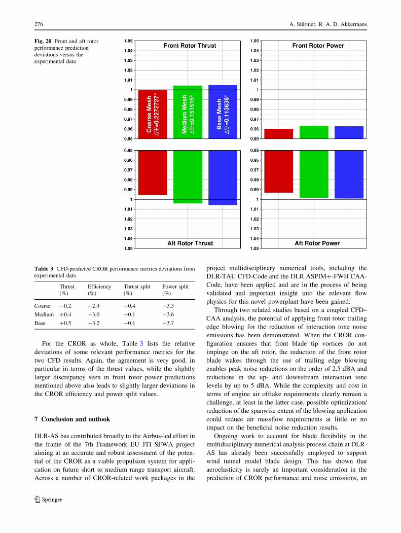
For all three meshes, Fig. 20 shows the performance
metrics of the front and aft rotor normalized with the
corresponding values in the experimental data. In each case
the CFD results for the smallest time step employed are
shown, as noted in the figure. For the individual rotor thrust
all meshes show a very good agreement with the experi-
mental data. The coarse mesh results give a nearly identical
front rotor thrust as the experiments, while the aft rotor
CFD data underpredicts thrust by 0.46 %. For the medium
mesh, both front and aft rotor thrust prediction are mar-
ginally larger than the wind tunnel results by around 0.4 %,
and the trend continues with the mesh refinement for the
baseline mesh, where both thrust values are around 0.5 %
larger than the experimental values. A similarly degree of
accuracy is achieved for the aft rotor power, with coarse,
medium and baseline mesh results agreeing with the wind
tunnel values with a marginal deviation of -0.7, -0.2 and
-0.09 %, respectively. Merely the front rotor power pre-
dictions show larger deviations, which range from -4 %
for the coarse mesh to around -3.8 % for the medium and
baseline mesh.
Fig. 17 Isolated CROR nearfield Chimera mesh setup
Fig. 18 Rotor–rotor interface meshing approach
Table 2 Isolated Z08-CROR mesh family overview
Baseline Medium Coarse
Farfield 14.6e6 cells 6.4e6 cells 1.9e6 cells
Nacelle 76.2e6 cells 32.2e6 cells 9.6e6 cells
Sting 19.3e6 cells 8.1e6 cells 2.4e6 cells
Front Rotor 42.9e6 cells 18.5e6 cells 5.4e6 cells
Aft Rotor 53.9e6 cells 22.8e6 cells 6.8e6 cells
Total 206.9e6 cells 88.1e6 cells 26.2e6 cells
Fig. 19 Time step size influence on blade wake vorticity transfer
through the Chimera interface for a circumferential slice at 50 %
blade radius in the medium mesh results
Smart fixed wing aircraft project 275
123
For the CROR as whole, Table 3 lists the relative
deviations of some relevant performance metrics for the
two CFD results. Again, the agreement is very good, in
particular in terms of the thrust values, while the slightly
larger discrepancy seen in front rotor power predictions
mentioned above also leads to slightly larger deviations in
the CROR efficiency and power split values.
7 Conclusion and outlook
DLR-AS has contributed broadly to the Airbus-led effort in
the frame of the 7th Framework EU JTI SFWA project
aiming at an accurate and robust assessment of the poten-
tial of the CROR as a viable propulsion system for appli-
cation on future short to medium range transport aircraft.
Across a number of CROR-related work packages in the
project multidisciplinary numerical tools, including the
DLR-TAU CFD-Code and the DLR ASPIM?-FWH CAA-
Code, have been applied and are in the process of being
validated and important insight into the relevant flow
physics for this novel powerplant have been gained.
Through two related studies based on a coupled CFD–
CAA analysis, the potential of applying front rotor trailing
edge blowing for the reduction of interaction tone noise
emissions has been demonstrated. When the CROR con-
figuration ensures that front blade tip vortices do not
impinge on the aft rotor, the reduction of the front rotor
blade wakes through the use of trailing edge blowing
enables peak noise reductions on the order of 2.5 dBA and
reductions in the up- and downstream interaction tone
levels by up to 5 dBA. While the complexity and cost in
terms of engine air offtake requirements clearly remain a
challenge, at least in the latter case, possible optimization/
reduction of the spanwise extent of the blowing application
could reduce air massflow requirements at little or no
impact on the beneficial noise reduction results.
Ongoing work to account for blade flexibility in the
multidisciplinary numerical analysis process chain at DLR-
AS has already been successfully employed to support
wind tunnel model blade design. This has shown that
aeroelasticity is surely an important consideration in the
prediction of CROR performance and noise emissions, an
Fig. 20 Front and aft rotor
performance prediction
deviations versus the
experimental data
Table 3 CFD-predicted CROR performance metrics deviations from
experimental data
Thrust
(%)
Efficiency
(%)
Thrust split
(%)
Power split
(%)
Coarse -0.2 ?2.9 ?0.4 -3.3
Medium ?0.4 ?3.0 ?0.1 -3.6
Base ?0.5 ?3.2 -0.1 -3.7
276 A. Sturmer, R. A. D. Akkermans
123

aspect that is under further study in present work in the
project. The next steps this effort are focused on improving
the blade FE-models to account for the actually manufac-
tured ply layup. With the cruise condition Z49 test in the
ONERA S1 wind tunnel just recently completed, DLR-AS
will draw on the experimental data to validate computa-
tions of both the static and dynamic aeroelastic deforma-
tions of the blades under test loading conditions and
investigate the impact of blade aeroelasticity on perfor-
mance and noise.
A large matrix of CROR simulations, including con-
figurations that are aimed at improving the understanding
of aerodynamic and aeroacoustic installation effects have
been performed. These studies have yielded valuable
insight into the complex flow physics of installed CROR
propulsion systems, demonstrated the capabilities of the
project partner’s numerical analysis tools and given insight
into areas of possible improvement in the CFD and CAA
predictions.
Current and future activities will focus on the validation
of all elements in the multidisciplinary numerical analysis
process chain, drawing on the substantial amount of high-
value wind-tunnel data becoming available from the Air-
bus-led tests of the Z08- and Z49-CROR models at cruise
and low-speed flight conditions. Current results for an
isolated CROR configuration show that performance pre-
dictions utilizing the DLR TAU-Code are able to match the
experimental test results with a high degree of accuracy on
grids that range in size from quite representative for current
industrial standards to highly refined. The validation
activities will demonstrate if the latter’s use results in
markedly better predictions of the farfield noise emissions.
Present pre-test results discussed in this paper indicate that
non-linear propagation effects can have an important
impact on the noise directivities. Thus, a study of the
placement of the permeable input surface in the APSIM?-
analysis is planned to check if these non-linear propagation
as well as aeroacoustic installation effects need to be
accounted for in the coupled CFD–CAA analysis.
Upcoming work will also focus on extending the validation
activities to the semi-installed as well as the fully installed
aircraft configurations.
Acknowledgments Airbus is greatly acknowledged for a fruitful
collaboration in the JTI SFWA project and for permitting publication
of this work.
Open Access This article is distributed under the terms of the
Creative Commons Attribution License which permits any use, dis-
tribution, and reproduction in any medium, provided the original
author(s) and the source are credited.
References
1. http://www.cleansky.eu/content/page/sfwa-0
2. Akkermans, R.A.D., et al.: ‘‘Handling of non-periodic contra
rotating open rotor data’’; AIAA 2012-2262. In: 18th AIAA
Aeroacoustics Conference, Colorado Springs (2012)
3. Kroll, N., Fassbender, J.K.: ‘‘MEGAFLOW—numerical flow
simulation for aircraft design’’. In: Notes on numerical fluid
dynamics and multidisciplinary design, vol. 89, pp. 81–92.
Springer, New York (2005)
4. Stuermer, A., Yin, J.: ‘‘The case for counter-rotation of installed
contra-rotating open rotor propulsion systems’’. In: AIAA2012-
2785, 30th AIAA Applied Aerodynamics Conference, New
Orleans (2012)
5. Stuermer, A., Yin, J.: Installation impact on pusher CROR engine
low speed performance and noise emission characteristics. Int J
Eng Syst Modeling Simul 4(1–2), 59–68 (2012)
6. Negulescu, C.: Airbus AI-PX7 CROR design features and aero-
dynamics. SAE Int. J. Aerosp. 6(2), 626–642 (2013). doi:10.
4271/2013-01-2245
7. Spalart, P.R., Allmaras, S.R.: ‘‘A one-equation turbulence model
for aerodynamic flows’’. In: AIAA1992-0439, (1992)
8. Jameson, A.: ‘‘Time dependent calculations using multigrid, with
applications to unsteady flows past airfoils and wings’’. In: 10th
AIAA Computational Fluid Dynamics Conference, Honolulu,
(1991)
9. Madrane, A., Raichle, A., Stuermer, A.: ‘‘Parallel implementation
of a dynamic unstructured chimera method in the DLR Finite
Volume TAU-Code’’. In: 12th Annual Conference of the CFD
Society of Canada, Ottawa, pp. 524–534, (2004)
10. Brentner, K., Farassat, F.: An analytical comparison of the
acoustic analogy and Kirchhoff formulation for moving surfaces.
AIAA J 36(8), 1379–1386 (1998)
11. Ffowcs Williams, J., Hawkings, D.: sound generation by turbu-
lence and surfaces in arbitrary motion. Phil. Trans. R. Soc. Lond.
264(1151), 321–342 (1969)
12. Di Francescantonio, M., Giles, M.: A new boundary integral
formulation for the prediction of sound radiation. J. Sound Vib.
202(4), 491–509 (1997)
13. Akkermans, R.A.D., Stuermer, A., Delfs, J.: ‘‘Assessment of
front-rotor trailing-edge-blowing for the reduction of open rotor
noise emissions’’. In: AIAA2013-2200; 19th AIAA/CEAS
Aeroacoustics Conference, Berlin
14. Akkermans, R.A.D., Stuermer, A., Delfs, J.: ‘‘Active flow control
for interaction noise reduction of contra-rotating open rotors’’. In:
AIAA2013-3799; 49th AIAA/ASME/SAE/ASEE Joint Propul-
sion Conference and Exhibit (JPC), San Jose
15. Stuermer, A., Yin, J.: Pylon trailing edge blowing for the control
of CROR unsteady blade loads. New Results Numer Exp Fluid
Mech VIII 121, 715–722 (2013)
16. Colin, Y., Caruelle, B., Parry, A. B.: ‘‘Computational strategy for
predicting CROR noise at low-speed Part III: investigation of
noise radiation with the Ffowcs Williams-Hawkings analogy’’.
In: 18th AIAA/CEAS Aeroacoustics Conference, Colorado
Springs (2012)
Smart fixed wing aircraft project 277
123