Multicylinder Diesel Engine for Low Temperature Combustion ... file1 2008 DEER Dearborn, MI August...
20
1 2008 DEER Dearborn, MI August 4-7 Multicylinder Diesel Engine for LTC operation Acknowledgements: DOE LTC consortium project, Low Temperature Combustion Demonstrator for High Efficiency Clean Combustion (DE-FC26- 05NT42413) . Industrial Partners: UCB, LLNL, Ricardo, Siemens, ConocoPhillips, BorgWarner, Mahle. William de Ojeda Phil Zoldak, Raúl Espinoza, Chunyi Xia, Dan Cornelius Navistar, Inc Raj Kumar University of Windsor Diesel Engine Development DOE DEER CONFERENCE Dearborn, Michigan August 4-8, 2008
Transcript of Multicylinder Diesel Engine for Low Temperature Combustion ... file1 2008 DEER Dearborn, MI August...

1
2008 DEERDearborn, MI August 4-7
Multicylinder Diesel Engine for LTC operation
Acknowledgements: DOE LTC consortium project, Low Temperature Combustion Demonstrator for High Efficiency Clean Combustion (DE-FC26- 05NT42413) .
Industrial Partners: UCB, LLNL, Ricardo, Siemens, ConocoPhillips, BorgWarner, Mahle.
William de OjedaPhil Zoldak, Raúl Espinoza, Chunyi Xia, Dan Cornelius
Navistar, Inc Raj Kumar
University of Windsor
Diesel Engine DevelopmentDOE DEER CONFERENCE
Dearborn, MichiganAugust 4-8, 2008

2
2008 DEERDearborn, MI August 4-7Goals and Objectives
• Demonstrate the application of low temperature combustion to:– Yield 2010 NOx and Soot in-cylinder emissions– Study is carried out on the Navistar 6.4L engine using today’s Diesel fuel– Target load 12.6 bar– Improve engine thermal efficiency
• Develop technology capable for production implementation.
2008 DEER
DevelopPredictive Capability
KIVA-CFD
CFDLLNL
Cylinder Pressure Feedback
PHASE IIIMulti-Cylinder Steady State Optimization
Dec 06June 06 Dec 07June 07 Dec 08June 08
Transfer Engine to Navistar
PHASE IV Control:Transient Response
Dec 05
PHASE IEngine Design
PHASE IIEngine Build
HCCI on 1 cyl
RICARDOBURR RIDGE
Combustion System OptimizationCombustion PhasingInjection StrategyCR sweepAir System
VVA testing
June 09
LTC2010 Emissions
AIRSystem MatchingBorg Warner, Mahle
Injection System SelectionSiemens
Misfire DetectionKnock SensorIon sensorCyl Pressure
ECU developmentIn-Cyl PressureCombustion Diagnostics
HP/LP EGR loop
Fuel Efficiencyimprovements
2008DEER
Fuel testingFuelselectionConocoPhillips
CN rangeand
FACE FUELS
2007DEER
Milestones(0.2gNOx engine out) BMEP~6bar 12bar 16bar

3
2008 DEERDearborn, MI August 4-7Goals and Objectives
Improve Thermal Efficiency
Optimize TC system / operationReduced back pressure
Optimize CR and ERVVA
Supporting work:
Engine Testing
1-D Cycle SimulationKIVA-CFD Modeling
Detail Energy BalanceDisc
usse
d He
re
2007baseline
Optimizedcombustion
40%
50%
55%
AirSystem
CoolingSystems
Parasitic Losses
DOE 2010
DOE 2013
Electrification Waste HeatRecoveryAdvanced
Platforms(VVA, LP EGR)
Fuels
Short combustion durationCombustion Phasing
Injection strategy (PPCI)VCR
Injector Bowl MatchInjection pressure
Emission Driven

4
2008 DEERDearborn, MI August 4-7Engine Build
Baseengine
V8Test Engine SCTE
Displac.BoreStroke
6.4L98.5mm105mm
6.4L98.5mm105mm
0.75L95mm105mm
FIE DICommon Rail
DICommon Rail
DICommon Rail
CR 16 12-16.5 15-16.5
Turbo Charger
Single StageVNT
Dual StageVNT Surge tank
EGR system HP loopSingle Cooler
HP loopDual Cooler cooled
IVCEVO
-133 BTDC132 ATDC
-133 BTDC132 ATDC
-133 BTDC132 ATDC
CAC
Engine
EGR
TexhPexh
Tw
TCAC
Pim Tim
Mair = f(DP)Tamb Pamb
Pc2 Tc2
T1
Tstack
Pstack
Hea
terT3T5T7
T2T4T6T8
TBP
CO2
CO2
CO2
SmokeNOxHCCOCO2
N
V(reg)
Tcharge Pcharge
P2P4P6P8
P1P3P5P7
N
emissions
IVC
IVC
FIE
FIE
EGR
PegrTegr
PegrTegr

5
2008 DEERDearborn, MI August 4-7Definition of LTC
0
0.2
0.4
0.6
0.8
1
0 2 4 6 8 10 12 14Exhaust O2 Concentration [%]
Indi
cate
d N
Ox
[g/k
W-h
r]
0
0.05
0.1
0.15
0.2
Indi
cate
d S
oot [
g/kW
-hr]
IMEP 7bar NOxIMEP 9bar NOxIMEP 7bar SootIMEP 9bar Soot
80 70 60 50 40 30EGR% ratio
Low Temperature CombustionPCI
Representative data from SCTEIMEP 7, 9 barN 1200 rpmPintake 2 barMf 28, 33 mg/stke
Ref. AVL
HCCI
HCCI: Lean, Homogenous (Φ ~ 0.2), Temp controlled ignition
LTC: Similar to Conven’l Diesel Diffusion (Φ ~ 1 -1.2) Very-high EGR (~60%)
PCCI: Improved mixture, increased ignition delay Higher injection pressuresFuel injection timing (closer to TDC)Less dependent on very-high EGRFurther bowl – injector matching
[Herzog et. al 1992][Akihama et. al 2001]

6
2008 DEERDearborn, MI August 4-7
Engine Mapping Optimization
02
46
81012
1416
1820
0 1000 2000 3000 4000rpm
BM
EP (b
ar)
Work in ProgressExtend LTC rangeFocus of Presentation
PCCI - LTCInjection pressureFuel injection strategyTemperature management
LTC - High EGRorHCCIMultiple shotsMedium EGR rate
Pres
ent R
ange
of te
stin
g DOE TARGET LINE
2007 Lug Line
Target of Program:Implement LTC trough 12.5 bar BMEP on a production platformMeet NOx and SOOT 2010 targets without after-treatmentPromote BSFC to meet 2007 levels and wok towards DOE targets of 50 to 55% efficiency.
7
2008 DEERDearborn, MI August 4-7
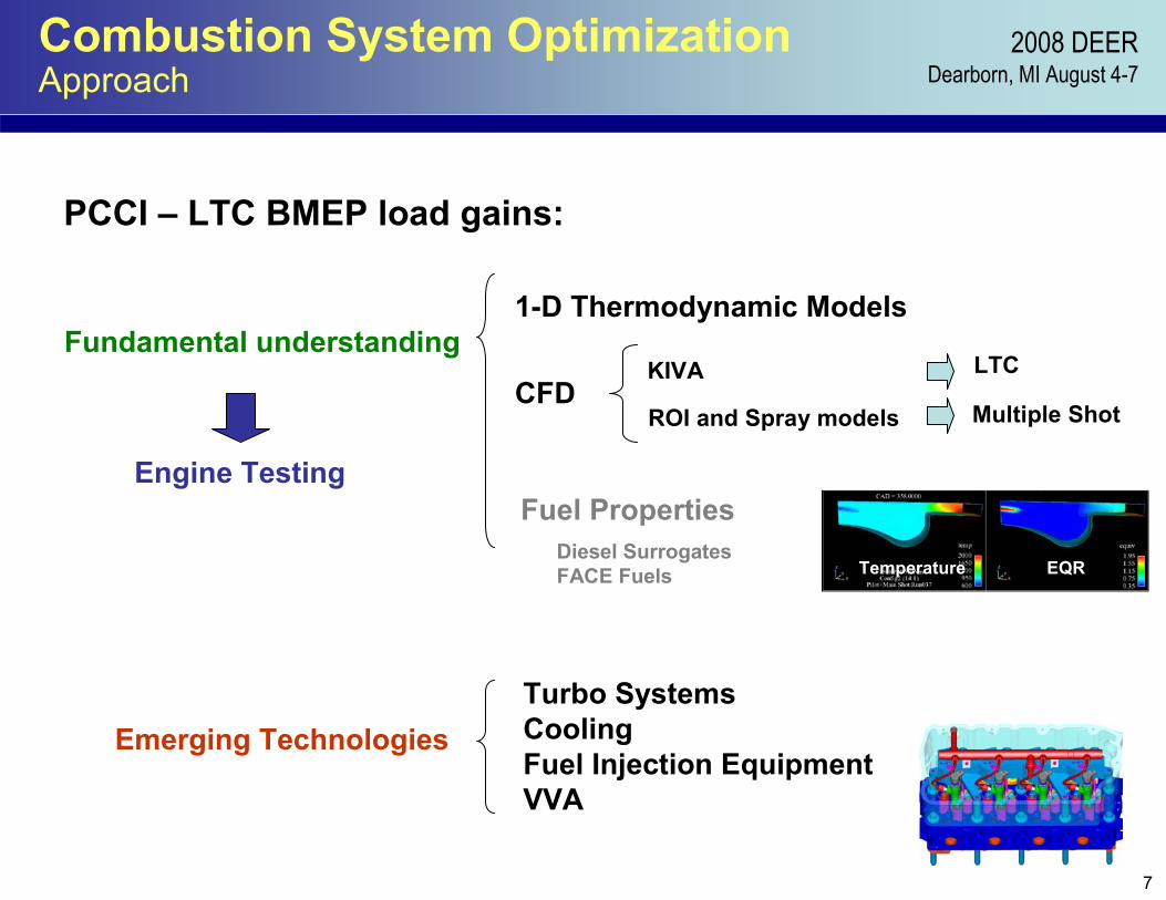
Combustion System Optimization Approach
PCCI – LTC BMEP load gains:
Fundamental understanding1-D Thermodynamic Models
CFDKIVA
Multiple ShotROI and Spray models
LTC
Temperature EQR
Emerging Technologies
Fuel Properties
Turbo SystemsCoolingFuel Injection EquipmentVVA
Diesel SurrogatesFACE Fuels
Engine Testing

8
2008 DEERDearborn, MI August 4-7
Combustion System Optimization Highlights
Injection strategy – Single ShotEffects of early timing vs. load increaseEffective NOx controlModeling and experimental correlations
Transition to Multiple ShotsMultiple PilotsEffective soot control (safeguard bsfc)Modeling and experimental correlations
Air System optimizationEffects on Injection Strategy on BSFCCoordinate EGR / TurboAdvantages of VVA
Summary
Current StatusOperating at ~ 16 bar BMEP
Can run with 40 - 50% EGR Yield 0.2gNOx/bhp-hrReasonable soot (0.05-0.1g/bhp-hr)High combustion Efficiency
Next steps Combustion optimization towards BSFC goals
Take a piece-wise approach (vs one-step to 50%)
FUP ~ comb durationFuel specific formulations (e.g. non-sooting)
Highlights

9
2008 DEERDearborn, MI August 4-7
Positive Impact of Early Injection (early PCCI)Single Shot Injection
Injection Strategy Combustion Phasing Optimization
Path to reduce in-cylinder PM• Optimize piston-injector match• Increased boost• Increase ignition delay (premixed burn)
- Increased injection pressure- Early injection timings
Path to reducing flame temps• Dilute charge O2 concentration (AFR)• Raise heat capacity of mixture (EGR)• Reduce fuel rich zones (strength)
CA earlyCA late
Emission Driven
CA late
CA early
Multi-Cylinder Engine Testing
Focus on Combustion mechanism at 1750 10.7 bar reducing NOx and SOOT with injection timing
At higher loads:- Multiple injections- Lower combustion temperatures

10
2008 DEERDearborn, MI August 4-7
Positive Impact of Early Injection (early PCCI)1. The local chemistry shows leaner and cooler combustion.2. The early injection aids to better entrainment and vaporization of the fuel.3. The rate of combustion is more rapid.
Injection Strategy Combustion Phasing Optimization
1750 rpm – 10.7 bar BMEPKIVA vs. Engine Data
Early SOI
Late SOI Line
Late SOI Line
1750 rpm 10.7 bar BMEP
-100
0
100
200
300
400
-30 -20 -10 0 10 20 30
Crank Angle (Ѳ)
Hea
t Rel
ease
(Jou
les/
deg)exp
sim
exp
sim
Early InjectionImage corresponds to Peak in HR trace
Temp Φ
Late Injection
Temp Φ

11
2008 DEERDearborn, MI August 4-7
Positive Impact of Early Injection (early PCCI)
Injection Strategy Combustion Phasing Optimization
1750 rpm – 10.7 bar BMEP
1750 rpm 10.7 bar BMEP
-500
50100150200250300
-30 -20 -10 0 10 20 30CAD
HR
(J/d
eg)
-5 +6
Simulations highlight the impact of injection timing in the throughout the combustion process including, ignition delay, premixed burn, mixing control burn.
Point of max hear release
rate
Late injection timings show cells longer residence time within the NOx formation island.
Temp φ

12
2008 DEERDearborn, MI August 4-7
162
164
166
168
170
172
174
176
0.16 0.18 0.20 0.22 0.24 0.26 0.28 0.30
NOx(g/hp-hr)
BSF
C (g
/hp-
hr)
1
2
3
4
5
6
Injection Strategy Transition to multiple-shot
0.05
0.10
0.15
0.20
0.25
0.30
0.16 0.18 0.20 0.22 0.24 0.26 0.28 0.30
NOx(g/hp-hr)
Smok
e (g
/bhp
-hr)
MainPilot+Main (35ppm NOx)Pilot+Main (32 ppm NOx)Pilot+Main+Post (32 ppm NOx)Retarded+High Injection PressureSoot limitNOx limit
1
2
3
4
5
6
EGR
1-23456
Combustion optimization is driven by emission requirements. Engine Data at1750 rpm – 10.7 bar BMEP
Next focus on pilot strategy
Options become reduced when fuel efficiency is to be preserved or improved.
The injection strategy can be tailoredto reduce soot and NOx.

13
2008 DEERDearborn, MI August 4-7
Injection Strategy Pilot-shot optimization
Optimization of pilot quantity
Pilot quantity is evaluated via soot and NOx tradeoff with respect to BSFC:
• Pilot quantity can reduce SOOT at constant fueling and NOx.• The effect of pilot is sensitive to a minimum quantity• Injection pressure and combustion phasing may weigh in to
further optimize the present tradeoff without excess penalty to fueling
• It is effective to reduce the max rate of pressure rise (A vs. B)
HC and CO with respect to BSFC• Combined contribution appears to be minimum vs. BSFC
A
B
Engine Data at1750 rpm – 10.7 bar BMEP
A B

14
2008 DEERDearborn, MI August 4-7
Injection Strategy Pilot-shot optimization
Optimization of pilot quantity
Simulations captured the ignition characteristics of the pilot events.Pilot liquid phase (A) vaporizes prior to main injection eventResults corraborate the BSFC – (HC,CO) balance from previous slide
1750 rpm – 10.7 bar BMEPSIMULATION vs. Experiments
pilot main
(A)
Next Slide
Cylinder Pressure
Heat release trace
Detail of Injection trace and fuel phase composition
Heat release trace

15
2008 DEERDearborn, MI August 4-7
Injection Strategy Pilot-shot optimization
1750 rpm – 10.7 bar BMEP14 mg pilot
SIMULATIONPilot mixture preparation
318
320
322
325
Temperature EQR
Pilot injection vaporizes
High temperaturePilot Combustion begins at 355º
Low temperature combustionBased on temperature distribution and heat release curve shows initial combustion at 340º
335
340
348
355
Start of main injection358
359
362
Suppression of the heat release from the main injection fuel occurs for approximately 4º
Temperature EQR
364
365
366
367
Main reaction take placePilot appears to ignite the main spray
0
50
100
150
200
250
300
-30 -20 -10 0 10 20 30
Crank Angle Degree
HR
R (J
/deg
)

16
2008 DEERDearborn, MI August 4-7
Injection Strategy high load testing
1670 rpm – 16 bar BMEP
140145150155160165170175180185190
0.1 1 10BSNOx (g/bhp-hr)
BS
FC (g
/bhp
-hr)
00.10.20.30.40.50.60.70.80.91
BS
OO
T (g/bhp-hr)
Baseline Engine
LTC@ <0.2gNOx
3%
5%
10-15%

17
2008 DEERDearborn, MI August 4-7
Air System Optimization Model Based Control
• Air system management coordinated EGR, ITH, VVA, VNT
• Fuel Injection management • In cylinder diagnostics • Modeling and simulation • Controls Rapid Prototype Systems
Systems Approach
2250 rpm - BMEP 9 barMultiple shotStrategies
Single shot
BSFC to DP:1% ~ 10kPa

18
2008 DEERDearborn, MI August 4-7
Air System Optimization VVA design and Impact on Engine Performance
VVA advantages:• Improve volumetric efficiency at low
speeds and loads• Improve emissions by increasing ignition
delay and reducing in-cylinder temperatures
• Maximize efficiencies and PCCI regions by using Miller-type cycles at part loads
BSFC improvements ~ 4%
FSN improvement islands ~ 2 FSN
Volumetric efficiency gains
Electro-hydraulic Intake Valve System control installed on the
Navistar 6.4 L V8 engine.

19
2008 DEERDearborn, MI August 4-7Summary
• Applied low temperature combustionTo target 2010 NOx engine out emissions using today’s Diesel fuel without active aftertreatment.
• Approach focused on the combustion system primarily looking to optimizea. The fuel injection strategy to favor premixing fuel into the charge cylinder mass. b. Optimize the operating boundary conditions, such as in-cylinder temperatures, EGR / in-cylinder O2 content.c. Improve brake thermal efficiency.d. Rely on CFD to understand behavior of with pilot injection (prediction of ignition delay, heat release)
• LTC was achieveda. With EGR, temperature management for BMEP load levels of 6 bar.b. With EGR, high injection pressure and early injection timing for loads from 6-12 bar.c. Transitioning ot a multi-shot strategy at 12-16 bar load levels.
• The technology gathered is capable for production implementation
• Future work will examine a. The impact of VVA in the engine emissions and BSFC.b. The effects of a variety of fuel formulations will be tested in this platform.

20
2008 DEERDearborn, MI August 4-7Acknowledgements
Project Partners
TM
Lawrence Livermore National Laboratory
CFD Fuels Enabling Technologies Combustion Diagnostics