Multicasting Ju Seong-ho 2002. 05.14. Previous work behind main one.
56
Multicasting Ju Seong-ho 2002. 05.14
-
Upload
tyrone-little -
Category
Documents
-
view
216 -
download
3
Transcript of Multicasting Ju Seong-ho 2002. 05.14. Previous work behind main one.

MulticastingJu Seong-ho2002. 05.14

Previous work behind main one

IGMP
Multicast groups are identified by class D IP addresses ( starting with 1110 )Use “host membership query” and “host membership report” message to support multicast group membershipQueries are sent to all-hosts group ( address 224.0.0.1)

DVMRP
Employ RPM(reverse path multicast) to send multicast packetsAssign each communication link a metric and threshold to specify link cost and to limit the scope of multicast, respectivelyPeriodically exchange routing table update messages with their neighbors

MOSPF
Extend OSPF by adding a new type of LSA, group membership LSAUse IGMP to keep track of group membership informationDistribute the information by flooding throughout ASSPT is computed on demand to conserve CPU and memory resource

CBT
Overcome two shortcomings of DVMRPCostly if NW consists of tens of thousands of nodes, of which only a few are multicast groupShould keep track of every (source,group) pair
Branches emanate from core routerDecrease the size of multicast routing tables at all routersUse JOIN/REQUEST messages

PIM
Avoid the overhead of broadcasting packets when group members sparsely populate the InternetTwo modes of operation : PIM-SM, PIM-DM
PIM-SM ( sparse mode )employ per-group rendezvous pointsUse unidirectional shared trees
PIM-DM ( dense mode )employ DVMRP methodUsed only if data rates exceed a certain value

BGMP
Facilitate multicast communication across different ASesUse TCP as its transport protocolBorder routers set up a TCP connection between themselves and exchange BGMP messages
MIGP component to participate in the MIGP protocol within ASBGMP component to construct a bidirectional center-based tree with other border routers

Source Filtering in IP Multicast Routing

What is Source Filtering?
Specify the reception of packets sent to a multicast group only from a list of source addressesExplicitly identify a list of the sources whose data the host does not want to receiveAvoid network bandwidth wastage caused by delivering unnecessary packets to local networks Discussed only in the context of local group management so far

Objectives
A multicast router will receive a multicast packet from a particular source if and only if at least one host in its directly attached network for from any downstream routersPromptly react to SF state updatesEnsure scalability in terms of low overhead in computing and communicationsMinimize modification to existing multicast routing protocols to support SF
SF in Source-Based Trees
For DVMRP / PIM-DMA tree is rooted at the flow source and spans all the group membersDR just prunes itself from the tree when no one in any directly attached network is interested in packets from a particular source

SF in Source-Based Trees (Cont’d)
For MOSPFUpon receiving the first multicast packet of a (source,group)pair, the router computes the shortest path tree based on the topology information and the source filtering statesRequire larger routing table size because each router needs to record the SF states of all other routers in the same OSPF area

SF in Shared Trees
Complicated problemEach tree is shared by all sources of the groupA source may or may not be a group memberPackets may be delivered unidirectionally or bi-directionallyChallenge for multicast routing protocols to enable source filtering while achieving scalability

Proposed Mechanism
Simple and low-overhead source filteringComprised of two parts
Forwarding partIdentify SF states stored in each interfaceDetermine to which interfaces a received multicast packet should be forwarded
Message exchange partExchange message to ensure the correctness of the SF treeMinimize network bandwidth wastage
First Forwarding Approach
Associate each outgoing interface with multiple SF states, each of which records the state of each downstream LANUnambiguously identify the outgoing interfaces to forward packets upon receiving themDon’t scale well because the memory size required by each SF router is proportional to the number of downstream LANs

Second Forwarding Approach
Associate each outgoing interface with one single SF state which summarizes the requirements of all the downstream LANsActivate outgoing interface when at least one host in any downstream LAN of the interface is interested in receiving source packetsSignificantly reduce forwarding table size of each router Improve routing efficiency

Forwarding Mechanism
Each entry in forwarding table stores the SF state information for one interfaceEach SF state includes a group address, a filter mode, and a source listActivate outgoing interface when
Filter mode is “include” and the source is in the associated source listFilter mode is “Exclude” and the source is not in the associated source list
Exchange Message Mechanism
Exchange message by flooding in unidirectional shared tree : not scalableMerge the SF states of all outgoing interface belonging to the same group
Improve scalability Minimize the overheadPropagate the resultant state upstream to the parent router

Exchange Message Mechanism(I)
Consider all the interfaces of an SF routerm “include” filter modes with m source lists
( I1, I2, …, Im )
N “exclude” filter modes with m source lists ( E1, E2,…, En )
Filter mode Mu, source list Su
Let I = I1∪ I2, ∪ … ∪ Im , E = E1 ∪ E2 ∪ … ∪En
If n=0, set Mu = include and Su = I ; otherwise, set Mu = exclude and Su = E-I

Exchange Message Mechanism (Cont’d)
Allow hosts to freely change their SF states
Require its upstream routers to reflect his change accordinglyMerge the table entries of all the other interfaces to generate a new state as soon as an SF state update is received from an interfaceForward the new state to its immediate upstream router

Exchange Message Mechanism (Cont’d)
Three drawbacks exist(1) Computational complexity of the merge
operation is proportional to the number of interfaces times the size of the source lists of the interfaces
(2) New merged state must be propagated upstream, irrespective of whether the new state remains unchanged
(3) If new state is slightly different from old state, it is inefficient to perform a merge to all entries and forward the result

Exchange Message Mechanism (Cont’d)
Solution for (2) Introduce “merge” entry storing merged stateDon’t forward the resultant state if the merge entry remains unchanged after merging
Solution for (3)Use IGMP message : Update, Allow, and BlockUpdate : deliver an entire SF stateAllow, Block : no filter mode, source list only

Exchange Message Mechanism(II)
Some notationBefore receiving an SF state update
Filter mode Fmo, source list Smo in merge entry
Filter mode Fio, source list Sio associated with the interface from which the update is received
Before receiving an SF state updateFilter mode Fmn, source list Smn in merge entry
Filter mode Fin, source list Sin associated with the interface from which the update is received
Exchange Message Mechanism (Cont’d)
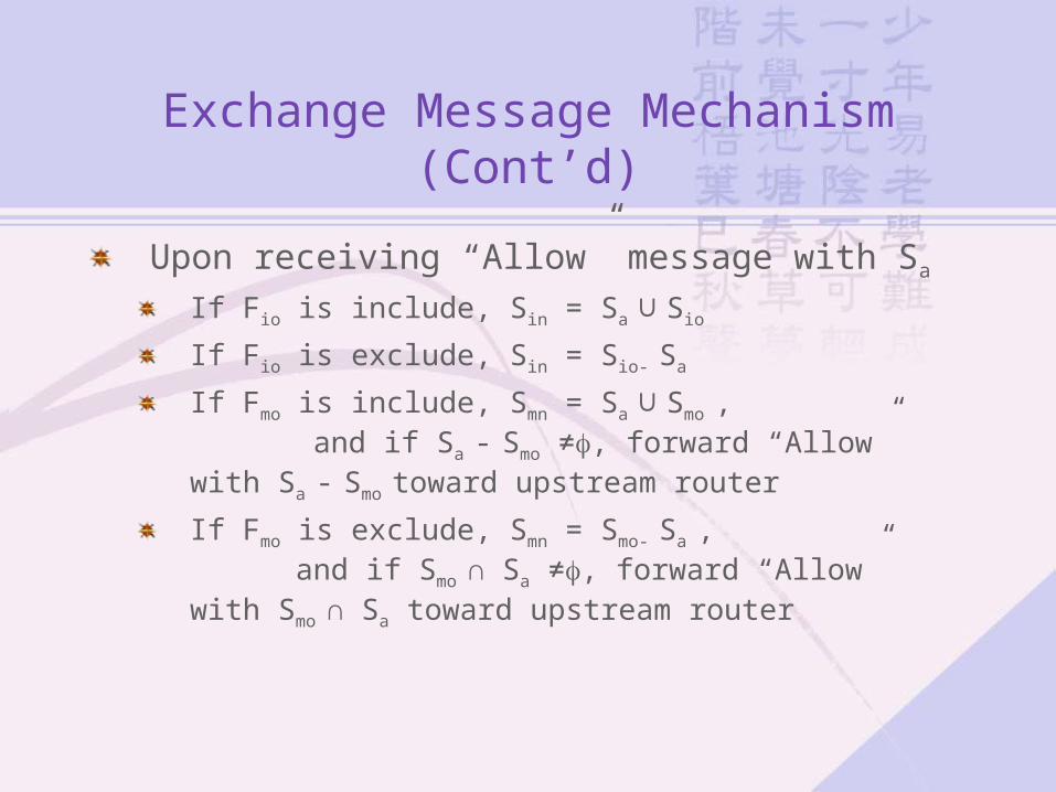
Upon receiving “Allow” message with Sa
If Fio is include, Sin = Sa ∪ Sio
If Fio is exclude, Sin = Sio- Sa
If Fmo is include, Smn = Sa ∪ Smo , and if Sa - Smo ≠, forward “Allow” with Sa - Smo
toward upstream routerIf Fmo is exclude, Smn = Smo- Sa , and if Smo ∩ Sa ≠, forward “Allow” with Smo ∩ Sa toward upstream router

Exchange Message Mechanism (Cont’d)
Upon receiving “Allow” message with Sb
If Fio is include, Sin = Sio- Sb
If Fio is exclude, Sin = Sio∪Sb
If Fmo is include, and check if any other interfaces are interested in source list Smo∪Sb If none exists, Smo= Smo-(Smo∪Sb) and then forward “Block” with source list Smo∪Sb
If Fmo is exclude, and check if any other interfaces are interested in source list Sb-Smo
If none exists, Smn = Smo∪Sb-Smo and then forward “Block” with source list Sb-Smo

Exchange Message Mechanism (Cont’d)
Upon receiving a change to the SF state or receiving “Update” with filter mode Fu and source list Su
If Fu and Fio are include, regard it as “Allow” with Su-Sio
and “Block” with Sio- Su
If Fu and Fio are exclude, regard it as “Allow” with Sio- Su
and “Block” with Su-Sio
If Fu and Fio are exclude and include respectively, set Fin=exclude and Sin= Su
If Fmo is include, check if any other interfaces are

Exchange Message Mechanism (Cont’d)
interested in source list Su∩Sio
If none exists,
set Fin=exclude and Smn= (Su-Smo) ∪(Su∩Sio),
then forward “Update” with Fmn and Smn
If Fmo is exclude, check if any other interfaces are
interested in source list Su ∩ Sio
If none exists, set Fin=exclude and Smn= (Su∩Smo) ∪(Su∩Sio),
then forward “Update” with Fmn and Smn

Exchange Message Mechanism (Cont’d)
If Fu and Fio are include and exclude respectively, set Fin=include and Sin= Su , then merge SF states of all interfaces to update merge entry
Forward update message to upstream router with Fmn and Smn dif
Receiving a join or leave message Regard it as update message Join message : Fio=include and Sio= ‘empty’
Leave message : Fu=include and Su= ‘empty’

Scalability of SF in IP Multicasting
A forwarding table in an SF router should be small
- Reduce memory size ( cost ) - Make forwarding efficiency - Support more multicast group
Communication and computational overhead should be as small as possible
- applicable even for a sizeable network

For Source-Based Trees
In source-based tree, a tree is constructed for each (source,group) pairAdopting DVMRP or PIM-DM
Memory size of a router
Communication overhead of the entire network
1 1
iSGi
memory ji j
C I E
1
Si
communication jj
C N M

For Source-Based Trees (Cont’d)
Adopting MOSPFMemory size required by each router
Communication overhead of the entire network
1 1
iNGi
memory ji j
C SF
communicationC L SF

For Shared Trees
In shared tree, a tree is shared by all sources of the groupRequired memory size
Generated communication overhead
1 1
iIGi
memory ji j
C SF
1 1
iINi
communication ji j
C SF

Simulation Results
Unidirectional shared tree Bi-directional shared tree
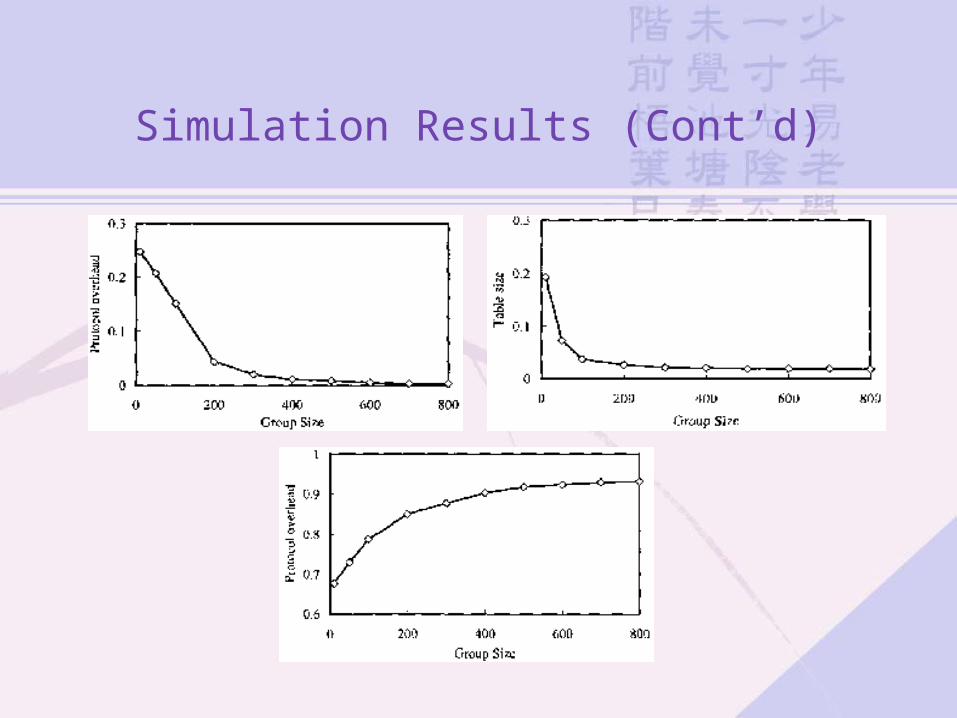
Simulation Results (Cont’d)

Conclusion
Propose a new mechanism to support the capability of source filtering in IP multicast routing protocolsAs compared with non-SF multicasting, better bandwidth utilization and scalability in terms of control overhead and forwarding table size Efficient use of resources for IP multicasting

Making Qos Aware Multicast Scalable in Terms of Link State
Advertisement
Qos Aware Multicast Procedures
Qos aware multicast tree construction and resource reservationQos aware forwarding
Multicast datagrams of a multicast group will be forwarded along with the Qos aware multicast tree for this traffic
Link state advertisement and Qos routing information update
Routing information including network topology and available bandwidth of links

Previous Works’ foci
First two procedures in the front pageNot consider scalability of link state advertisementLarge number of messages for link state advertisement will be exchanged over the world every time a new Qos aware multicast tree is constructed

Proposed Protocol
Advertisement of information on links within a domain is limited within that domainOnly link state information of inter-domain links is advertised among the border multicast routersCrank back mechanism is used
Retry to construct a new Qos aware multicast tree

Design Principles
Multicast network is divided into domainsIntra-domain and inter-domain is introducedRange of link state advertisement exchange is limited for intra-domain and inter-domain levels
For the intra-domain multicastingUse PIM-SM as an intra-domain multicast routing protocol and OSPF for intra-domain link state advertisementUse SPT as a Qos aware multicast tree

Design Principles (Cont’d)
For the inter-domain multicastingUse BGMP as an inter-domain multicast routing protocol and BGP-4 for inter-domain link state advertisementOthers are the same as intra-domain
When an SPT spreads over multiple domainsUse only the information on available bandwidth of links within this domain and inter-domain linksThe construction will be failed because of no knowledge about other domains
Design Principles (Cont’d)
Crank back mechanismA failure of tree construction is reported back to the original domain of Qos Join message Another trial of SPT construction is performed through different domainsIntroduce Join NACK message to PIM-SM and BGMP
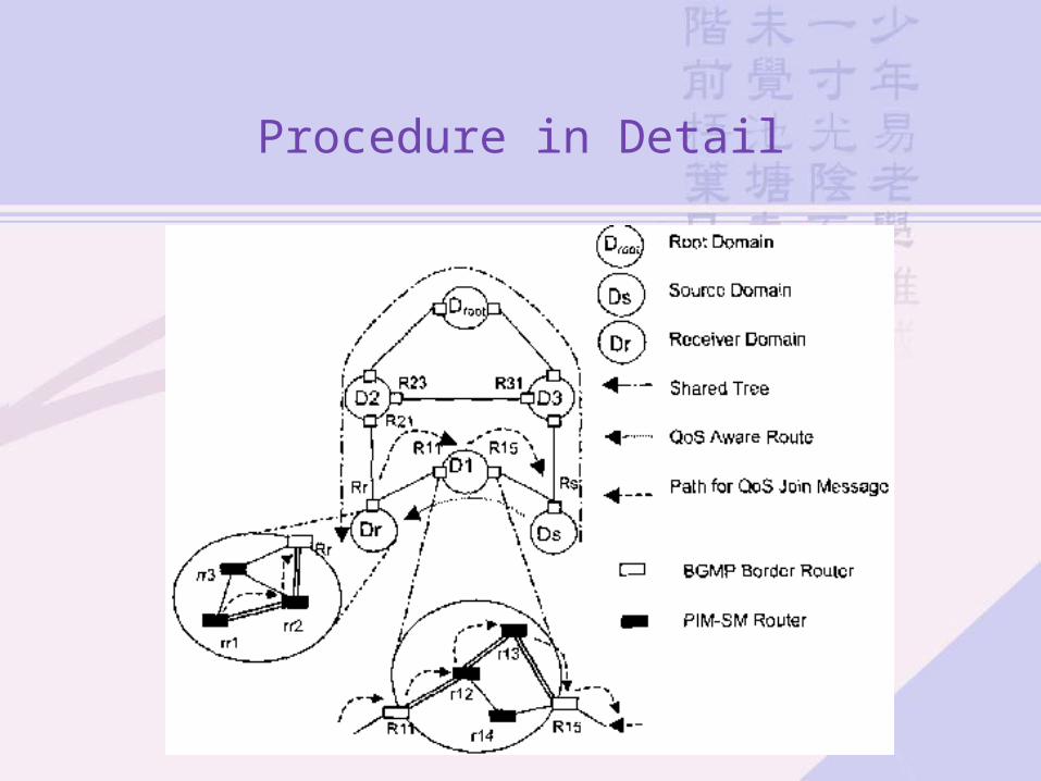
Procedure in Detail
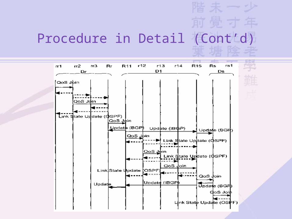
Procedure in Detail (Cont’d)

Procedure in Detail (Cont’d)

Proposed Message Format
For intra-domain,Extend Join message in PIM-SM to assign a new type value for Qos Join message and a new parameter, Required Qos Link Information Add a new parameter for reporting updated available bandwidth in Link State Update message for bandwidth advertisement
For inter-domain,Introduce new attributes same as for intra-domain to support the proposed multicast routing protocol

Crank Back Mechanism

Crank Back Mechanism (Cont’d)
< Format of Join NACK Message for BGMP >
< Format of Join NACK Message for PIM-SM >
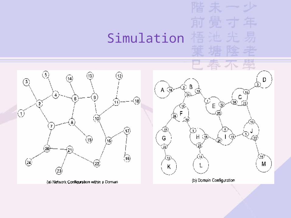
Simulation

Simulation Conditions
Evaluate the number of exchanged link state advertisement messages
- OSPF Link State Update messages and BGP Update messages
Only the leaf routers in a domain initiate a Qos Join attempt All Qos Join messages will succeedAll of the links have the same costs
- Qos aware multicast tree within a domain is constructed using the shortest path
Simulation Conditions (Cont’d)
A Qos Join message will be forwarded until the router that has been already receiving the multicast traffic which this Qos Join message is requestingOne Link State Update message is used to be delivered to one routerWhen a Qos Join message is sent over an inter-domain link, BGP or IBGP Update message is delivered to each border router in the whole network

Simulation Conditions (Cont’d)
One Update message is used to be delivered to one border routerEvaluate case of flat network configuration
- Exchange OSPF Link State Update messages if the bandwidth of a link is newly reserved
Two kinds of simulation environment 1. There is only one sender in the whole network 2. There is one sender in each domain 3. Their locations are selected randomly in both cases
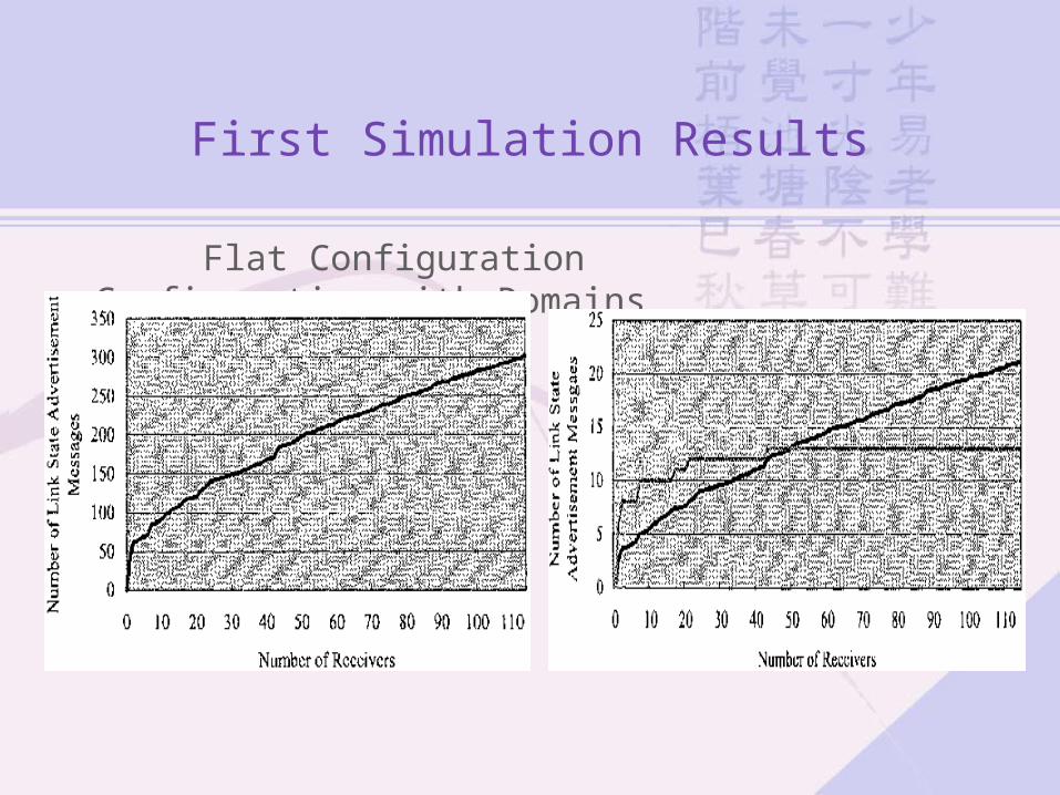
First Simulation Results
Flat Configuration Configuration with Domains

Second Simulation Results
Flat Configuration Configuration with Domains

Conclusion
Multicast network is divided into domainsRange of link state advertisement is limited within one domainAmong BGMP border multicast routers, only the link state information of inter-domain links is advertisedIntroduce Crank Back Mechanism in case of tree construction failureReduce the number of exchanged link state advertisement messages by the order of 1/(number of domains)