
Multi User Security
254
ABSTRACT Title of Dissertation: MULTI-USER SECURITY FOR MULTICAST COMMUNICATIONS The ub iquit y of communi cation ne two rks is facilitating the development of wireless and Internet applications aimed at allowing users to communicate and collaborate amongst themselves. In the future, group-oriented services will be one of the dominant services that facilitate real-time information exchange among a large number of diverse users. However, before these group-oriented services can be successful deployed, technologies must be developed to guarantee the secu ri ty of the in formation and da ta exchan ge d in gr ou p comm un ications. Among all security re qu ir emen ts of gr ou p communication, access control is paramount as it is the first line of defense that prevents unauthorized access to the group communication and protects the value of application data. Access control is usually achieved by encrypting the data using a key that is shared among all legitimated group members. The problem of access control becomes more difficult when the content is distributed to a dynamic group with user joining and leaving the service for a variety of reasons. Thus, Group Key Management is required to achieve key update with dynamic group membership. Existing group key management schemes seek to minimize either the amount of rounds needed in establishing the group key, or the size of
Transcript of Multi User Security

8/14/2019 Multi User Security
http://slidepdf.com/reader/full/multi-user-security 1/254
ABSTRACT
Title of Dissertation: MULTI-USER SECURITY FOR
MULTICAST COMMUNICATIONS
The ubiquity of communication networks is facilitating the
development of wireless and Internet applications aimed at allowing
users to communicate and collaborate amongst themselves. In thefuture, group-oriented services will be one of the dominant services
that facilitate real-time information exchange among a large number
of diverse users. However, before these group-oriented services can
be successful deployed, technologies must be developed to guarantee
the security of the information and data exchanged in group
communications. Among all security requirements of group
communication, access control is paramount as it is the first line of
defense that prevents unauthorized access to the group
communication and protects the value of application data. Access
control is usually achieved by encrypting the data using a key that is
shared among all legitimated group members. The problem of accesscontrol becomes more difficult when the content is distributed to a
dynamic group with user joining and leaving
the service for a variety of reasons. Thus, Group Key Management is
required to achieve key update with dynamic group membership.
Existing group key management schemes seek to minimize either the
amount of rounds needed in establishing the group key, or the size of

8/14/2019 Multi User Security
http://slidepdf.com/reader/full/multi-user-security 2/254
the key updating messages. They do not, however, considering the
varying requirements of the users, the underlying networks or the
applications. Those generic solutions of access control often yield
large consumption of communication, computation and storage
resources, especially for large groups with highly dynamic
membership in heterogeneous networks. In addition, the design of
existing key management schemes focus on protecting the application
data, but introduces vulnerabilities in protecting the statistics of group
membership information. This poses severe security concern invarious group applications. The focus of this dissertation is to design
network-specific and application specific group key management and
solve the security vulnerability of key management that reveals
dynamic group membership information. This dissertation will
present scalable group key management in heterogeneous wireless
network, the hierarchical access control for multimedia applications,
and a framework of securing dynamic group membership information
over multicast. The main contribution of this dissertation
is to advance the group key management research to achieve higher
level of scalability and security.
MULTI-USER SECURITY FOR MULTICAST
COMMUNICATIONS
TABLE OF CONTENTS
1 Introduction 1

8/14/2019 Multi User Security
http://slidepdf.com/reader/full/multi-user-security 3/254
1.1 Motivation . . . . . . . . . . . . . . . . . . . . . . . . . . . . . . . . 1
1.2 Security Issues in Group Communications . . . . . . . . . . . . . . 3
1.2.1 Access Control and Data Confidentiality . . . . . . . . . . . 3
1.2.2 Service Authentication and Verification . . . . . . . . . . . . 4
1.3 Key Management for Group Access Control . . . . . . . . . . . . . 6
1.3.1 Centralized Key Management . . . . . . . . . . . . . . . . . 6
1.3.2 Contributory Key Management . . . . . . . . . . . . . . . . 9
1.4 Thesis Overview and Contribution . . . . . . . . . . . . . . . . . . 13
2 Topology-aware Key Management for Wireless Networks 192.1 Introduction . . . . . . . . . . . . . . . . . . . . . . . . . . . . . . . 19
2.2 Topology-Matching Key Management Tree . . . . . . . . . . . . . . 20
2.3 Handoff Schemes for TMKM Tree . . . . . . . . . . . . . . . . . . . 25
2.4 Performance Analysis . . . . . . . . . . . . . . . . . . . . . . . . . . 29
2.5 Separability of the Optimization Problem . . . . . . . . . . . . . . . 34
2.6 Design of the TMKM Tree . . . . . . . . . . . . . . . . . . . . . . . 36
2.6.1 Dynamic membership model . . . . . . . . . . . . . . . . . . 37
2.6.2 ALX tree structure . . . . . . . . . . . . . . . . . . . . . . . 38
2.6.3 User subtree design . . . . . . . . . . . . . . . . . . . . . . . 43
2.6.4 BS subtree design . . . . . . . . . . . . . . . . . . . . . . . . 43
2.6.5 SH subtree design . . . . . . . . . . . . . . . . . . . . . . . . 45
2.7 Simulation Results . . . . . . . . . . . . . . . . . . . . . . . . . . . 48
2.7.1 One-SH systems . . . . . . . . . . . . . . . . . . . . . . . . . 48
2.7.2 Multiple-SH systems . . . . . . . . . . . . . . . . . . . . . . 51
3 Hierarchical Group Access Control 57
3.1 Introduction . . . . . . . . . . . . . . . . . . . . . . . . . . . . . . . 57

8/14/2019 Multi User Security
http://slidepdf.com/reader/full/multi-user-security 4/254
3.2 Hierarchical Access Control for Group Communications . . . . . . .
59
3.2.1 System description . . . . . . . . . . . . . . . . . . . . . . . 59
3.2.2 Security requirements . . . . . . . . . . . . . . . . . . . . . . 60
3.2.3 Data encryption and hierarchical key management . . . . . . 62
3.3 Centralized Multi-group Key Management Scheme . . . . . . . . . .
63
3.3.1 Employing independent key trees to achieve hierarchical accesscontrol . . . . . . . . . . . . . . . . . . . . . . . . . . . 63
3.3.2 Multi-group key management scheme . . . . . . . . . . . . . 64
3.4 Performance Measures and Analysis . . . . . . . . . . . . . . . . . . 68
3.4.1 Storage overhead . . . . . . . . . . . . . . . . . . . . . . . . 69
3.4.2 Rekey overhead . . . . . . . . . . . . . . . . . . . . . . . . . 72
3.5 Simulations and Performance Comparison . . . . . . . . . . . . . . 73
3.5.1 Statistical dynamic membership model . . . . . . . . . . . . 74
3.5.2 Performance with different group size . . . . . . . . . . . . . 76
3.5.3 Scalability . . . . . . . . . . . . . . . . . . . . . . . . . . . . 79
3.5.4 Performance with different transition probability . . . . . . . 80
3.5.5 Simulation of multi-service applications . . . . . . . . . . . . 82
3.6 Contributory Multi-group Key Management . . . . . . . . . . . . . 83
4 Protecting Dynamic Group Information in Secure Multicast 87
4.1 Introduction . . . . . . . . . . . . . . . . . . . . . . . . . . . . . . . 87
4.2 GDI Attacks on Centralized Key management . . . . . . . . . . . . 88
4.2.1 Attack A1: Estimation of the number of join/departure users
by inside attackers . . . . . . . . . . . . . . . . . . . . . . . 89

8/14/2019 Multi User Security
http://slidepdf.com/reader/full/multi-user-security 5/254

8/14/2019 Multi User Security
http://slidepdf.com/reader/full/multi-user-security 6/254
viii
LIST OF FIGURES
1.1 A typical key management tree . . . . . . . . . . . . . . . . . . . . 6
1.2 Key structure . . . . . . . . . . . . . . . . . . . . . . . . . . . . . . 7
1.3 Key management architecture in centralized scenario . . . . . . . . 9
1.4 Tree-based contributory key management . . . . . . . . . . . . . . . 11
1.5 Key Management architecture in centralized sceneries . . . . . . . .
12
2.1 A cellular wireless network model . . . . . . . . . . . . . . . . . . . 222.2 A Topology -matching key management tree . . . . . . . . . . . . . 23
2.3 Key update process when user u moves from cell i to cell j . . . . .
26
2.4 Key update process when user u leaves the service from cell j . . .
29
2.5 Comparison of the wireless cost and the wireline cost for one user
departure . . . . . . . . . . . . . . . . . . . . . . . . . . . . . . . . 32
2.6 ALX tree . . . . . . . . . . . . . . . . . . . . . . . . . . . . . . . . 38
2.7 Comparison between the ALX tree performance and the lower
bound
for different user joining rates . . . . . . . . . . . . . . . . . . . . . 41
2.8 Comparison between the ALX tree performance and the lower
bound
for different average service duration . . . . . . . . . . . . . . . . . 42
2.9 An example of the SH subtree . . . . . . . . . . . . . . . . . . . . 46
2.10 The cost pairs on the SH subtree . . . . . . . . . . . . . . . . . . . 47

8/14/2019 Multi User Security
http://slidepdf.com/reader/full/multi-user-security 7/254
2.11 (a) The total message size as a function of the wireless weight;
(b)
Performance ratio as a function of the wireless weight . . . . . . . . 49
2.12 (a) Performance ratio for different user join rate; (b) Performance
ratio for different users’ maximum speed. . . . . . . . . . . . . . . . 50
2.13 Comparison among SH subtree design methods . . . . . . . . . . . 52
2.14 Performance comparison in multiple-SH systems with identical
SHs 53
2.15 Performance comparison in multiple-SH systems with non-identical
SHs . . . . . . . . . . . . . . . . . . . . . . . . . . . . . . . . . . . 54
2.16 A TMKM tree containing 5 SHs . . . . . . . . . . . . . . . . . . . 55
3.1 Independent-tree key management scheme for layered coded
multimedia
service . . . . . . . . . . . . . . . . . . . . . . . . . . . . . . 64
3.2 Multi-group key management graph construction . . . . . . . . . . 65
3.3 User relocation on the key graph . . . . . . . . . . . . . . . . . . . 67
ix
3.4 Discrete Markov chain model for multi-layer applications. . . . . .
75
3.5 Storage overhead at the KDC . . . . . . . . . . . . . . . . . . . . . 78
3.6 Storage overhead at the users in each SG . . . . . . . . . . . . . . . 78
3.7 Rekey overhead at the KDC . . . . . . . . . . . . . . . . . . . . . . 78
3.8 Rekey overhead at the users in each SG . . . . . . . . . . . . . . . . 79
3.9 Storage overhead at the KDC with different number of SGs . . . . .
80

8/14/2019 Multi User Security
http://slidepdf.com/reader/full/multi-user-security 8/254
3.10 Rekey overhead at the KDC with different number of SGs . . . . .
81
3.11 Rekey overhead at the KDC with different transition probability .
. 81
3.12 Rekey overhead at the KDC with unevenly loaded SGs in
multiservice
applications . . . . . . . . . . . . . . . . . . . . . . . . . . 83
3.13 The total number of rounds performed to establish the group
key . 843.14 The number of rounds performed by the users in each SG for key
establishment . . . . . . . . . . . . . . . . . . . . . . . . . . . . . . 85
3.15 The number of rounds performed to establish the group key with
different number of SGs/layers . . . . . . . . . . . . . . . . . . . . 85
4.1 Performance of the ML estimator . . . . . . . . . . . . . . . . . . . 93
4.2 The anti-attack scheme using phantom users and batch rekeying . .
99
4.3 The GDI of a long audio session in MBone . . . . . . . . . . . . . . 108
4.4 Upper bound of the GDI leakages . . . . . . . . . . . . . . . . . . . 109
4.5 Communication overhead M ( L0;N 0; d ) . . . . . . . . . . . . . . . . 110
4.6 Illustration of selecting optimal parameters L0 and N 0. . . . . . . .
111
4.7 The GDI leakage versus communication overhead for a real
MBone
audio session . . . . . . . . . . . . . . . . . . . . . . . . . . . . . . 112
4.8 The GDI leakage versus communication overhead for a simulated
multicast session . . . . . . . . . . . . . . . . . . . . . . . . . . . . 113

8/14/2019 Multi User Security
http://slidepdf.com/reader/full/multi-user-security 9/254
x
Introduction
1.1 Motivation
Point-to-point communication has been the dominant form of
computer network communication since the beginning of networking.
However, with the explosive advancement of networking and
information technologies that bring a large amount of users to
communicate and collaborate, point-to-point communications faces
severe calability challenges in a variety of emerging applications [1].² Digital video and audio multicast over Internet, such as movie-on-
demand and video conferences. Widespread software distribution,
such as anti-virus scanner update and security patch delivery.
² Disseminating real-time financial market information to a large
audience with various devices, including PDAs, cell phones,
computers etc.² Transportation control where road traffic pattern or air
traffic control information is distributed to many stations.
Multi-player games involving thousands of users simultaneously
interacting in a virtual game world.
Distributing information to a large audience cannot be achieved over
point-topoint communications without causing congestion andwasting network resources. For group-oriented applications, Multicast
is an essential mechanism to achieve scalable information
distribution.Multicast describes communication where information is
sent from one or more parties to a set of other parties. In this case,
information is distributed from one or more senders to a set of
receivers, but not to all users. Multicast is different from broadcast
8/14/2019 Multi User Security
http://slidepdf.com/reader/full/multi-user-security 10/254
where information is distributed to all users. The subtle difference
between broadcast and multicast can be neglected in many context.
Significant advancement has been seen recently, in both the
underlying multicast networking technology as well as the
deployment of applications utilizing multicast . Already there are
multicast services that stream stock quotes, and provide video and
audio on demand. In the future, multicast applications will be running
in wireless mobile environment, as consumers desire to have a similar
suite of multimedia-intensive applications on their portable devices asthey currently have available to them at their desktops.
Multicast has the advantage of efficient distributing information to
thousands or even millions of users. However, multicast also creates
opportunities for malicious packets to reach thousands or millions of
users, and introduces difficulties in maintaining security with dynamic
group membership. In this chapter, we will first review security issues
in group communications, then discuss some drawbacks of existing
security mechanisms, and finally summarize the contribution of
thisthesis.
2
1.2 Security Issues in Group Communications
In general, group communications consider the following security
requirements.Confidentiality non-group members cannot read the data
Integrity data cannot be modified or deleted in any unauthorized way
Authentication claimed sender is the actual sender Access Control
only authorized parties can access the group communications Non-
repudiation Recipient can prove what messages it receives No denial-

8/14/2019 Multi User Security
http://slidepdf.com/reader/full/multi-user-security 11/254
of-service No interference by un-authorized parties 1.2.1 Access
Control and Data Confidentiality Among all those requirements,
access control is the first line of defense needed to
protect the value of application data. A service provider may control
access to
content by encrypting the content using a key that is shared by all
valid group
members. The problem of access control becomes more difficult
when the contentis distributed to a group of users. Since group membership will most
likely be
dynamic with users joining and leaving the service for a variety of
reasons, it is
necessary to update the group key. The issues of key generation and
update are
addressed by Key Management protocols [3, 4]. In addition,
encryption and key
management together ensure data confidentiality because
unauthorized entities do
not possess the group key and cannot decrypt group communication.
The main problem of group key management is to update keys in
dynamically
changing group such that a receiver can decrypt the data only when he
is a valid
3

8/14/2019 Multi User Security
http://slidepdf.com/reader/full/multi-user-security 12/254
group member. In particular, a group key management protocol
should satisfy the
following security requirements.
² Group key secrecy - non-group members cannot obtain any group
key.
² Backward secrecy - the join user cannot decrypt the content that was
sent
before his join.
² Forward secrecy - the departure/revoked user cannot decrypt thecontent
that is sent after his deletion from the group.
To achieve forward and backward secrecy, the group key is updated
after each
member join and departure event, and the new key information is
distributed to
the legitimated group members . It is important to update and
distribute keys in
a secure, scalable and reliable way. In Chapter 1.4, these issues will
be discussed
in detail. Here we list the properties that a good key management
scheme should
have.
² Low communication, computation and storage overhead
² Scalability for large dynamic groups
² Reliable distribution of key update messages

8/14/2019 Multi User Security
http://slidepdf.com/reader/full/multi-user-security 13/254
² The ability of detecting dishonest group members and recovering
from key
generation failure.
1.2.2 Service Authentication and Verification
Multicast Authentication is another essential security mechanism that
ensures data
integrity and validates the source of the data. Authentication can be
achieved in
4an asymmetric manner such as digital signatures. Although digital
signatures can
solve the authentication problem, they are inefficient due to their
prohibitive computational
overhead [5–7]. In point-to-point communications, data authentication
is usually achieved through a symmetric manner where the sender and
the receiver
share a secret key to compute a message authentication code (MAC)
of all communicated
data. When a message with a correct MAC arrives, the receiver is
assured
that the sender generated that message. However, symmetric
authentication is
generally not secure in multicast because every group member knows
the MAC
key and can impersonate the sender. It is required that every receiver
can verify

8/14/2019 Multi User Security
http://slidepdf.com/reader/full/multi-user-security 14/254
the authenticity of messages without being able to generate authentic
messages,
which is asymmetric in nature. Currently, the most popular multicast
authentication
schemes use the principle of delayed key disclosure in order to
achieve
the asymmetry needed for multicast authentication using symmetric
cryptography
[8–12]. Those schemes require time synchronization between thesource and
the receivers. The main idea is to have the sender attach a MAC to
each packet
computed using a key known only to itself. The receivers buffer the
received packets
without being able to authenticate them. A short time after the
delivery of
the packets, the sender discloses the key and the receivers are later
able to authenticate
the packets. After the key is disclosed, the receivers will not accept
the
packages with MAC generated by this key. A representative of such
authentication
schemes is TESLA. Interested readers can refer to [11] for the details
of TESLA
and other multicast authentication schemes. In addition, non-
repudiation problem

8/14/2019 Multi User Security
http://slidepdf.com/reader/full/multi-user-security 15/254
and prevention of Denial-of-service attack in secure multicast
communications are
relatively new topics. Some studies can be found in [13–15]. In this
dissertation,
the focus is access control for secure group communications.
5
1 2 3 4 5 6 7 8 9 10 11 12 13 14 15 16
K000
K00KS
Ke
u1 u2 u3 u16 ......
K0 K1
K01 K10 K11
K001 K010 K011 K101 K100 K110 K111
Users
Private
Keys
SK
KEKs
Figure 1.1: A typical key management tree
1.3 Key Management for Group Access Control
Key management schemes can be classified as centralized schemes
and contributory
schemes [16]. In centralized schemes, group members trust a
centralized server,

8/14/2019 Multi User Security
http://slidepdf.com/reader/full/multi-user-security 16/254
referred to as the key distribution center (KDC), which generates and
distributes
encryption keys [4, 16–24]. In contributory schemes, group members
are trusted
equally and all participate in the formation of the group key [25–33].
In this section,
we introduce popular centralized and contributory key management
schemes.
1.3.1 Centralized Key ManagementThe most common class of centralized key management schemes
employ a tree
hierarchy to maintain the keying material [3, 16–19]. As illustrated in
Figure 1.1,
each node of the key tree is associated with a key. The root of the key
tree is
associated with the session key (SK), Ks, which is used to encrypt the
multicast
content. Each leaf node is associated with a user’s private key, ui,
which is only
known by this user and the KDC. The intermediate nodes are
associated with
6
Fixed ID Version Revision Secrete material
key selector key content
Figure 1.2: Key structure

8/14/2019 Multi User Security
http://slidepdf.com/reader/full/multi-user-security 17/254
key-encrypted-keys (KEK), which are auxiliary keys and only for the
purpose of
protecting the session key and other KEKs. To make concise
presentation, we do
not distinguish the node and the key associated with this node in the
remainder
of the thesis.
Each key contains the secrete material that is the content of the key
and a key selector that is used to distinguish the key. As illustrated in Figure
1.2, the key
selector consists of: 1) a unique ID that stays the same even if the key
content
changes and 2) a version and revision field, reflecting update in the
keying material.
The version number is increased whenever new keying material is
sent out by
the group manager upon user departure, while the revision number is
increased
whenever the key is passed through a one-way function. The usage of
the version
and revision numbers will be explained in the description of the key
updating
process.
Each user stores his private key, the session key, and a set of KEKs
on the

8/14/2019 Multi User Security
http://slidepdf.com/reader/full/multi-user-security 18/254
path from himself to the root of the key tree. In the example shown in
Figure
1.1, user 16 possesses fu16;Ks;K²;K 1;K 11;K 111 g . When a user
leaves the service,
all his keys need to be updated in order to prevent him from accessing
the future
communication. Here we use the scheme presented in [18] to
demonstrate the key
updating process. When user 16 leaves, the KDC generates new keysand conveys
new keys to the remaining users through a set of rekeying messages
as:
² fKnew
111 gu15 : user 15 acquires Knew
111 ,
7
² fKnew
11 gKnew
111 , fKnew
11 gKold
110
: user 13,14,15 acquire Knew
11 ,
² fKnew
1 gKnew
11

8/14/2019 Multi User Security
http://slidepdf.com/reader/full/multi-user-security 19/254
, fKnew
1 gKold
10
: user 9; ¢ ¢ ¢ ; 15 acquire Knew
1 ,
² fKnew
" gKnew
1 , fKnew
² gKold 0
: user 1; ¢ ¢ ¢ ; 15 acquire Knew
² ,
² fKnew
s gKnew
² : all remaining users acquire Knew
s ,
where the notation xold represents the old version of key x, xnew
represents the new
version of key x, and fygx represents the key y encrypted by key x.
The version
numbers are increased for all new keys. This key updating procedure
guarantees
that all remaining users obtain the new session key and KEKs, while
user 16 is
unable to acquire the new keys. Since the rekeying messages are
transmitted in the

8/14/2019 Multi User Security
http://slidepdf.com/reader/full/multi-user-security 20/254
multicast channel [17], every user receives all rekeying messages. The
session key,
KEKs and users’ private keys usually have the same length. The
communication
overhead associated with key updating can be described by rekeying
message size,
defined as the amounts of rekeying messages measured in the unit as
the same size
as the SK or KEKs. In this example, the rekeying message size is 8when user
16 leaves the service. It has been shown that the rekeying message
size increases
linearly with the logarithm of the group size [18].
When a user joins the service, the KDC chooses a leaf position on the
key
tree to put the joining user. The KDC updates the keys along the path
from the
new leaf to the root by generating the new keys from the old keys
using a oneway
function and increasing the revision numbers of the new keys. The
joining
user obtains the new keys through the unicast channel. Other users in
the group
will know about the key change when the data packet indicating the
increase of

8/14/2019 Multi User Security
http://slidepdf.com/reader/full/multi-user-security 21/254
the revision numbers first arrives, and compute the new keys using
the one-way
function. No additional rekeying messages are necessary.
8
Multicast Control Flow
Multicast Data Flow
Unicast
KDC
AdmissionControl
Key
Management
Sender
Key
Manager
Encryption
Data Source
Receivers
Key
Manager
Decryption
Data App.
______
___ ___
_ __ ____ _____ ___
_____ _ ____

8/14/2019 Multi User Security
http://slidepdf.com/reader/full/multi-user-security 22/254
___ ____
_____ _ ____
___ ____
Policy
Infrastructure
Trust
Infrastructure
Group Key
ManagementPlane
Figure 1.3: Key management architecture in centralized scenario
In summary, Figure 1.3 illustrates the high level diagram of
centralized access
control mechanism for group communications. All users register at
the Key Distribution
Center (KDC) that generates and distributes keys. With the group
session
key, secure communication can be established between the sender and
the receivers
through the data security protocol . The KDC knows group
membership changes
through the registration protocol and then updates keys through the
rekey protocol
by transmitting a set of rekeying messages in the multicast channel.
1.3.2 Contributory Key Management

8/14/2019 Multi User Security
http://slidepdf.com/reader/full/multi-user-security 23/254
In some scenarios, it is not preferred to rely on a centralized server
that arbitrates
the establishment of the group key. This might occur in applications
where group
members do not explicitly trust a single entity, or there are no servers
or group
9
members who have sufficient resources to maintain, generate, and
distribute keyinginformation. Thus, the distributed solution of the key agreement
problem has
drawn considerable attention [25–33].
The contributory schemes do not rely on centralized servers. Instead,
every
group member makes independent contribution and participates the
process of
group key establishment, and the members’ personal keys are not
disclosed to
any other entities. The early design of contributory key agreements
mostly considers
the efficiency of key generation for the initial establishment of the
group
key [25, 27, 28, 34]. Among them, Ingemarsson et al. first introduced
a conference
key distribution system based on a ring topology [25]. Later,
Burmester and

8/14/2019 Multi User Security
http://slidepdf.com/reader/full/multi-user-security 24/254
Desmedt proposed a key distribution system that takes only three
rounds to generate
a group key [27]. Steiner et al. extended the two-party Diffie-Hellman
(DH)
protocol and proposed group Diffie-Hellman protocols GDH.1/2/3
[28, 29]. Becker
and Willie studied the communication complexity of contributory key
agreements
and proposed the octopus and 2d-octopus protocols [34]. Whileachieving efficient
initial key establishment, most of these schemes encounter high
rekeying complexity
upon membership changes. Recent research on key management
becomes more
aware of the scalability issue in both key establishment and key
update for large
and dynamic groups. After the tree-based approaches were proposed
in the centralized
scenario [4, 17], logical tree structure is also used in the contributory
setting
by Kim et al in their TGDH scheme [31], and by Dondeti et al in their
DISEC
scheme [32].
Next, we briefly review tree-based contributory key management
schemes [31,

8/14/2019 Multi User Security
http://slidepdf.com/reader/full/multi-user-security 25/254
32] that use the two-party DH protocol [35] as a basic module. Let A
and B denote
two entities, KA denote the private key of A, and KB denote the
private key of B.
10
<0,0>
<1,0> <1,1>
<2,0> <2,1> <2,2> <2,3>
M1 M 2 M 3 M 4(a) a key tree
<0,0>
<1,0> <1,1>
<2,0> <2,1> <2,2> <2,3>
M1 M 2 M 3
<3,6>
M4 M 5
<3,7>
New intermediate
node
New member
(b) user join
Figure 1.4: Tree-based contributory key management
Two-party DH protocol establishes a share key between A and B
without revealing
their private keys as follows. First, A sends the message fgKA mod pg
to B, and
8/14/2019 Multi User Security
http://slidepdf.com/reader/full/multi-user-security 26/254
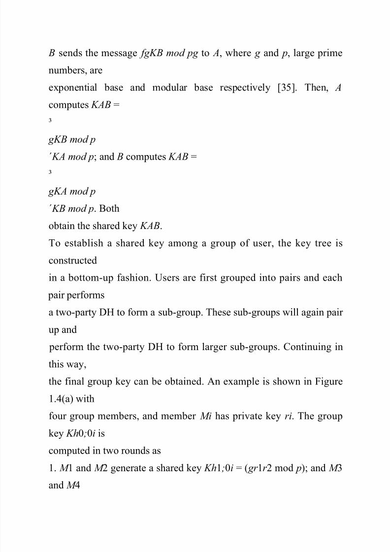
B sends the message fgKB mod pg to A, where g and p, large prime
numbers, are
exponential base and modular base respectively [35]. Then, A
computes KAB =
³
gKB mod p
́KA mod p; and B computes KAB =
³
gKA mod p ́KB mod p. Both
obtain the shared key KAB.
To establish a shared key among a group of user, the key tree is
constructed
in a bottom-up fashion. Users are first grouped into pairs and each
pair performs
a two-party DH to form a sub-group. These sub-groups will again pair
up and
perform the two-party DH to form larger sub-groups. Continuing in
this way,
the final group key can be obtained. An example is shown in Figure
1.4(a) with
four group members, and member Mi has private key ri. The group
key Kh0;0i is
computed in two rounds as
1. M 1 and M 2 generate a shared key Kh1;0i = ( gr 1r 2 mod p); and M 3
and M 4

8/14/2019 Multi User Security
http://slidepdf.com/reader/full/multi-user-security 27/254
generate a shared key Kh1;1i = ( gr 3r 4 mod p). Then, M 1 and M 2
form a
subgroup; and M 3 and M 4 form a subgroup.
2. Two subgroups perform two-party DH protocol and generate the
group key
11
Receivers
Admission
ControlEncryption
Data Source
Data App.
Decryption
Contributory
Key
Management
__________ _
_ ____ __ _ _
_ _______
__ _ _
Group Key
Management Plane
Policy
Infrastructure
Trust
Infrastructure

8/14/2019 Multi User Security
http://slidepdf.com/reader/full/multi-user-security 28/254
Multicast Control Flow
Multicast Data Flow
Unicast
____
_ _____ ___
__ _ _
network
network
Figure 1.5: Key Management architecture in centralized sceneriesas Kh0;0i = ( gKh1;0iKh1;1i mod p):
In a user join event, the new user will first be paired with an insertion
node,
which could be either a leaf node or an inner node, to perform a two-
party DH.
Then all the keys on the path from the insertion node to the tree root
are updated
recursively. An example is shown in Figure 1.4(b). When member M 5
joins the
group, the insertion node is chosen as node h2; 3i in Figure 1.4(a),
then M 4 and
M 5 perform one round of DH to generate a new inner node h2; 3i in
Figure 1.4(b),
followed by the key updates on the path h2; 3i ! h1; 1i ! h0; 0i.
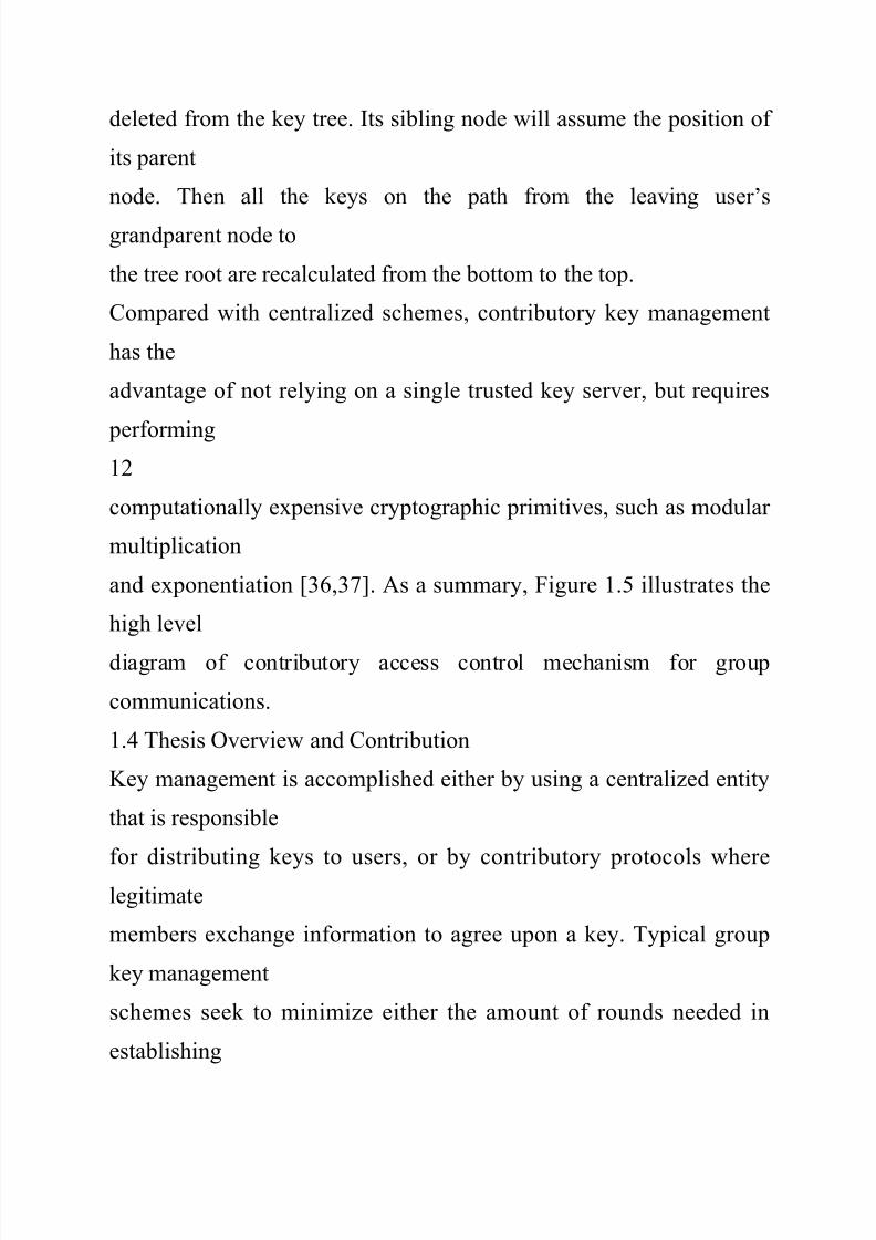
Upon a user’s departure, the leaving user’s node and its parent node
will be
8/14/2019 Multi User Security
http://slidepdf.com/reader/full/multi-user-security 29/254
deleted from the key tree. Its sibling node will assume the position of
its parent
node. Then all the keys on the path from the leaving user’s
grandparent node to
the tree root are recalculated from the bottom to the top.
Compared with centralized schemes, contributory key management
has the
advantage of not relying on a single trusted key server, but requires
performing12
computationally expensive cryptographic primitives, such as modular
multiplication
and exponentiation [36,37]. As a summary, Figure 1.5 illustrates the
high level
diagram of contributory access control mechanism for group
communications.
1.4 Thesis Overview and Contribution
Key management is accomplished either by using a centralized entity
that is responsible
for distributing keys to users, or by contributory protocols where
legitimate
members exchange information to agree upon a key. Typical group
key management
schemes seek to minimize either the amount of rounds needed in
establishing
8/14/2019 Multi User Security
http://slidepdf.com/reader/full/multi-user-security 30/254
the group key, or the size of the rekeying messages. However, those
approaches do
not factor in the varying requirements of the users, the underlying
network, or the
application, and are therefore not well suited to provide efficient
solutions for all
users, for all networks, or for all types of applications. The first two
components
of this dissertation focus on tailoring access control solutions towireless networks
where users are mobile and the medium is inherently unreliable, and
to multimedia
applications where the rich properties of the content allow for an
improved design
of key management. All these scenarios introduce challenges that are
not present
in conventional key management for generic applications. In order to
design better
security protocols, it is necessary to look at the security system from
an adversarial
point-of-view. The third component of this dissertation addresses a
security
concern in popular key management schemes and proposes a
framework to immunize
the key management protocols. Next, we introduce these three
components

8/14/2019 Multi User Security
http://slidepdf.com/reader/full/multi-user-security 31/254
individually.
Topology-aware key management in wireless networks
To achieve forward and backward security, rekeying messages are
sent to group
13
members when there are users joining or leaving the multicast group.
In applications
where there are many users and frequent additions or deletions to the
groupmembership, key management can introduce a significant
communication burden.
rekeying messages must be delivered reliably because the loss of
rekeying messages
results in severe performance degradation [3]. If a user loses one key,
he will not
be able to access multicast content encrypted by this key and may not
be able
to acquire future keys from future rekeying messages either. Further,
in real-time
multicast applications the rekeying messages should also be delivered
in a timely
manner so that users receive the rekeying messages before the new
key takes effect.
These reasons alone motivate the need for building communication-
efficient
8/14/2019 Multi User Security
http://slidepdf.com/reader/full/multi-user-security 32/254
key management schemes. In wireless multicast scenarios, however,
the need is
even more pronounced since bandwidth is limited and data typically
experience a
higher transmission error rate than in conventional environments.
In the first part of this dissertation, we propose a method for designing
a centralized
multicast key management tree for a group of users in a cellular
network.Traditional tree-based multicast key management schemes do not
consider the
effect of the network topology upon the delivery of the rekeying
messages, and
therefore waste network resources by sending rekeying messages to
users who do
not need them. We address this issue by proposing to match the key
management
tree to the network topology, thereby localizing the delivery of the
rekeying messages
and reducing the communication costs. In mobile environments, the
user
will subscribe to a multicast service under an initial host agent, and
through the
course of his service undergo handoff to different base stations. We
will discuss

8/14/2019 Multi User Security
http://slidepdf.com/reader/full/multi-user-security 33/254
issues arising from user relocation and present a handoff scheme that
is suitable
for topology-matching key management. In addition, we prove that
optimizing
14
the proposed key tree is equivalent to optimizing a set of independent
smallerscale
subtrees. This significantly reduces the complexity of the tree design.
Atree structure that can easily adapt to changes in the number of users
and a tree
generation algorithm that considers the heterogeneity of the network
will also be
introduced.
Hierarchical Group Access Control
Existing key management schemes, such as in [4, 16–33], address the
access
control issues in a single multicast session. They focus on establishing
and updating
keys with dynamic membership and provide all group members the
same level of
access privilege. That is, the users who possess the decryption keys
have the
full access to the content, and the users who do not have the
decryption keys

8/14/2019 Multi User Security
http://slidepdf.com/reader/full/multi-user-security 34/254
cannot interpret the data. In practice, many group applications contain
multiple
related data streams and have the members with various access
privileges. These
applications prevail in various scenarios.
² Multimedia applications distributing data in multi-layer coding
format [38].
For example, in a video broadcast, users with a normal TV receiver
canreceive the normal format, while others with HDTV receivers can
receive
both the normal format and the extra information needed to achieve
HDTV
resolution.
² Multicast programs containing several related services, such as
weather,
news, traffic and stock quote.
² Communications in hierarchically managed organizations, such as
military
group communications where participants have various access
authorization.
Since group members subscribe to different data steams, or possibly
multiple of
15
them, it is necessary to develop access control mechanism that
supports the multilevel

8/14/2019 Multi User Security
http://slidepdf.com/reader/full/multi-user-security 35/254
access privilege, which shall be referred to as the hierarchical group
access
control .
The access control issue for each data stream can be managed
separately using
existing key management schemes . However, this leads to inefficient
use of keys
and does not scale well when the number of data streams increases. In
the second part of this dissertation, we develop a multi-group key management
scheme
that addresses the generalized hierarchical group access control
problem. Particularly,
we design an integrated key graph that maintains the keying material
for
all members with different access privileges and incorporates new
functionalities
that are not present in conventional multicast key management, such
as the user
relocation on the key graph. The proposed multi-group key
management scheme
achieves forward and backward secrecy [31] when users (1) join the
group communication
with certain access privilege; (2) leave the group; and (3) add or drop
the subscription of one or several data streams (change access
privilege). The

8/14/2019 Multi User Security
http://slidepdf.com/reader/full/multi-user-security 36/254
idea of the integrated key graph can be used in both centralized and
contributory
environments. Compared with using single-session access control
solutions, such
as a variety of tree-based key management scheme [18, 31], the
proposed scheme
reduces the usage of the communication, computation and storage
overhead, and
is scalable when the number of access levels increases.Securing Dynamic Group Membership Information
Key management is employed to prevent unauthorized access to
multicast content.
We discovered, however, the rekeying process associated with
multicast key
management can disclose information about the dynamics of the
group membership
to both insiders and outsiders. We collectively refer to group
dynamics in-
16
formation (GDI) as information describing the dynamic membership
of a group
application, such as the number of users in the multicast group as a
function of
time, and the number of users who join or leave the service during a
time interval.

8/14/2019 Multi User Security
http://slidepdf.com/reader/full/multi-user-security 37/254

8/14/2019 Multi User Security
http://slidepdf.com/reader/full/multi-user-security 38/254
broadcast nature of the wireless media enables anyone within the
broadcast range
to observe the encrypted data.
In the third part of this dissertation, we demonstrate that the key
management
schemes can reveal the GDI easily and propose a framework of
protecting GDI from
inside and outside attackers. We have developed two effective
strategies to attack and steal information about the membership dynamics from the tree-
based centralized
schemes [3, 4,16–19] that employ tree hierarchy for the maintenance
of keying
material. These strategies involve exploiting the format of rekeying
messages and
estimating GDI directly from the size of the rekeying messages. We
also developed
17
an anti-attack method that is fully compatible with the existing key
management
schemes. By utilizing batch rekeying [39] and introducing phantom
users, the proposed
anti-attack method aims to minimize the mutual information between
the
rekeying process observed by the attackers and the true group
dynamics. Various

8/14/2019 Multi User Security
http://slidepdf.com/reader/full/multi-user-security 39/254
aspects of the proposed anti-attack scheme, such as the
communication overhead
and the leakage of GDI, are evaluated based on the data obtained from
MBone
sessions. The analysis on other non-tree based schemes is also
provided. In contributory
key management, each group member need to be aware of other
group
members in order to establish the shared group key. Thus, the task of protecting
GDI is more difficult than it is in the centralized scenario. We provide
qualitative
analysis on the vulnerability of various contributory schemes and
techniques that
can be used to protect GDI in the distributed environments.
The rest of the dissertation is organized as follows. The topology-
matching
key management scheme for wireless networks is discussed in
Chapter 2. The keygraph
based hierarchical group access control is presented in Chapter 3. In
Chapter
4, we discuss attack and protection technologies for dynamic group
membership
information. Conclusion and future work is in Chapter 5.
18
Chapter 2

8/14/2019 Multi User Security
http://slidepdf.com/reader/full/multi-user-security 40/254
Topology-aware Key Management
for Wireless Networks
2.1 Introduction
There has been significant advancements in building a global wireless
infrastructure
that will free users from the confines of static communication
networks. Users will
be able to access the Internet from anywhere at anytime. As wireless
connections become ubiquitous, consumers will desire to have multicast
applications running
on their mobile devices. In order to meet such a demand, there has
been increasing
research efforts in the area of wireless multicast [40–42].
In wireless networks, where bandwidth is limited and transmission
error rate
is high, the design of key management schemes need to consider the
transmission
of the rekeying messages in order to ensure reliable key distribution
and reduce
the communication burden associated with key management. Previous
key management
schemes focus entirely on generating the rekeying messages, but they
neglect the issues of the delivery of the rekeying messages and do not
consider the
19

8/14/2019 Multi User Security
http://slidepdf.com/reader/full/multi-user-security 41/254
underlying network topology.
In this Chapter, we propose a topology-aware centralized key
management
scheme for multicast applications in a cellular network. By matching
the key
management tree to the network topology and localizing the delivery
of rekeying
messages, we can significantly reduce the communication burden
associated withrekeying. In Section 2.2, we introduce the concept of matching the
key tree to the
network topology and motivate the reduction in the communication
cost associated
with rekeying. In mobile environments, the user will subscribe to a
multicast
service under an initial host agent, and through the course of his
service undergo
handoff to different base stations. In Section 2.3, we discuss issues
arising from user
relocation and present a handoff scheme that is suitable for topology-
matching key
management. In Section 2.4, we analyze the effect that matching the
key tree to
topology has upon the communication overhead. We then address the
complexity

8/14/2019 Multi User Security
http://slidepdf.com/reader/full/multi-user-security 42/254
of designing the key management tree in Section 2.5 by proving that
optimizing
the proposed key tree is equivalent to optimizing a set of independent
smallerscale
subtrees. This significantly reduces the complexity of the tree design.
We
describe, in Section 2.6, a tree structure that can easily adapt to
changes in the
number of users and a tree generation algorithm that considers theheterogeneity
of the network. We then describe a procedure to build the key tree and
determine
the parameters that optimize the tree. Finally, simulation results are
presented in
Section 2.7.
2.2 Topology-Matching Key Management Tree
In this section, we introduce the benefits of matching the key tree to
the network
topology. We outline a procedure to design the key management tree
and
20
define the cost functions that we use in the rest of the chapter for
measuring the
communication burden associated with key updating.
Let us revisit the example of tree-based centralized key management
in Section

8/14/2019 Multi User Security
http://slidepdf.com/reader/full/multi-user-security 43/254
4.2.3 (see Figure 1.1). As user 16 leaves the multicast service, all of
his keys
are updated through a set of rekeying messages. It is seen that most
rekeying
messages are only useful to a subset of users, who are always
neighbors on the
key management tree. In fact, the first rekeying message is only
useful to user 15,
the second rekeying message is only useful to users 13,14,15, thethird rekeying
message is useful to users 9; 10; ¢ ¢ ¢ ; 15, and the fourth and fifth
rekeying messages
are useful to all users. Therefore, rekeying messages do not have to be
sent to
every user in the multicast group.
We propose to exploit this observation in designing a key
management tree.
Our key management tree will match the network topology in such a
way that
the neighbors on the key tree are also physical neighbors on the
network. By
delivering the rekeying messages only to the users who need them, we
may take
advantage of the fact that the key tree matches the network topology,
and localize

8/14/2019 Multi User Security
http://slidepdf.com/reader/full/multi-user-security 44/254
the delivery of rekeying messages to small regions of the network.
This lessens the
amount of traffic crossing portions of the network that do not have
users who need
to be rekeyed. In order to accomplish this, it is necessary to have the
assistance
of entities that would control the rekeying message transmission, such
as the base
stations in cellular wireless networks.A cellular network model, as depicted in Figure 2.1 and proposed in
[43], consists
of mobile users, base stations (BS) and supervisor hosts (SH). The
SHs administrate
the BSs and handle most of the routing and protocol details for mobile
users.
The service provider, the SHs, and the BSs are connected through
high-speed wired
21
Service
Provider Network
SH
SH
SH
Base Station
Non group members
group members

8/14/2019 Multi User Security
http://slidepdf.com/reader/full/multi-user-security 45/254
Figure 2.1: A cellular wireless network model
connections, while the BSs and the mobile users are connected
through wireless
channels. In this work, the SHs can represent any entity that
administers BSs,
such as the region servers presented in [44] and radio network
controllers (RNCs)
in 3G networks [45]. In cellular wireless networks, multicast
communication can be implemented efficiently by exploiting the inherent broadcasting
nature of the
wireless media [46–48]. In this case, multicast data is first routed to
the BSs using
multicast routing techniques designed for wireline networks [2], and
then broadcast
by the BSs to mobile users.
If we assume that both the SHs and the BSs can determine whether
the rekeying
messages are useful for the users under them, then the cellular
wireless network
has the capability of sending messages to a subset of users. In
particular, the SHs
multicast a rekeying message to their BSs if and only if the message is
useful to
one or several of their BSs, and the BSs broadcast the rekeying
message to their

8/14/2019 Multi User Security
http://slidepdf.com/reader/full/multi-user-security 46/254
users if and only if the message is useful to the users under them. The
information
needed to identify whether a SH or BS needs a rekeying message can
be sent
in the rekeying message header. We shall not consider the size of this
overhead
22
BS BS BS BS
SHSH
BS BS
BS
SH
……
KDC
Figure 2.2: A Topology -matching key management tree
information in our calculation since this overhead is typically small
compared to
the size of the actual rekeying messages, and is implementation-
dependent. Hence,
when the key tree matches the network topology, we can localize the
delivery of
rekeying messages.
We design a key management tree that matches the network topology
in three
steps:

8/14/2019 Multi User Security
http://slidepdf.com/reader/full/multi-user-security 47/254
² Step 1: Design a subtree for the users under each BS. These subtrees
are
referred to as user subtrees.
² Step 2: Design subtrees that govern the key hierarchy between the
BSs and
the SH. These subtrees are referred to as BS subtrees.
² Step 3: Design a subtree that governs the key hierarchy between the
SH and
the KDC. This subtree is referred to as the SH subtree.The combined key management tree is called a Topology-Matching
Key Management
(TMKM) tree. Figure 2.2 illustrates a TMKM tree for the network
topology
shown in Figure 2.1. Traditional key management trees, such as those
in [16–19],
23
are independent of the network topology, and we call them Topology
Independent
Key Management (TIKM) trees. When using a TIKM tree, the users
are scattered
all over the network, and therefore it is not possible to localize the
delivery
of rekeying messages.
We study the communication burden of the rekeying messages in the
wired

8/14/2019 Multi User Security
http://slidepdf.com/reader/full/multi-user-security 48/254
portion and in the wireless portion of the network separately. Under
each SH, the
wireline-message-size is defined as the total size of the rekeying
messages multicast
by the SHs to the BSs, and the wireless-message-size is defined as the
total size
of the rekeying messages broadcast by the BSs. The message size is
measured in
units whose bit length is the same size as the key length. In this work,we assume
that the network connection between the KDC and the SHs has ample
bandwidth
resource and experience very low error rate. Thus, the wireline-
message-size does
not include the communication overhead between the KDC and the
SHs.
Let Sl
1 denote the wireline-message-size under the lth SH and Sl
2 denote the
wireless-message-size under the lth SH, where l = 1; 2; ¢ ¢ ¢ ; nsh
and nsh is the total
number of SHs. For example, when the length of the session key and
KEKs is
128 bits each, if a 256 bit long rekeying message is multicast by the
lth SH and
then broadcast by 3 BSs under the lth SH, then Sl

8/14/2019 Multi User Security
http://slidepdf.com/reader/full/multi-user-security 49/254
1 = 2 and Sl
2 = 6. Assuming
that users do not leave simultaneously, then the rekeying wireline
cost, Cwire, the
rekeying wireless cost Cwireless, and the total rekeying cost CT , are
defined as:
Cwire =
Xnsh
l =1®l
1 E [Sl
1] ; Cwireless =
Xnsh
l =1
®l
2 E [Sl
2 ]
CT = ° ¢ Cwireless + (1 ¡ °) ¢ Cwire (2.1)
where E [:] indicates expectation over the statistics governing the user
joining and
leaving behavior. Here, 0 · ° · 1 is the wireless weight , which
represents the importance
of considering the wireless cost, and f®l
1 g and f®l
2 g are the sets of weight
24

8/14/2019 Multi User Security
http://slidepdf.com/reader/full/multi-user-security 50/254
factors that describe the importance of considering the wireline-
message-size and
wireless-messages-size under the lth SH respectively. When SHs
administrate areas
with similar physical network structure and channel conditions, we
can approximate
f®l
1 g and f®l
2 g by 1. In addition, we define the combined-message-size asSl
T = ° ¢Sl
2®l
2 +(1¡°) ¢Sl
1®l
1. Thus, CT can also be expressed as CT =
Pnsh
l =1 E [Sl
T ].
For a given wireless weight °, f®l
1 g , and f®l
2 g , both the TMKM and TIKM
trees should be designed to minimize the total communication cost,
CT .
2.3 Handoff Schemes for TMKM Tree
In mobile environments, the user will subscribe to a multicast service
under an
8/14/2019 Multi User Security
http://slidepdf.com/reader/full/multi-user-security 51/254
initial host agent, and through the course of his service move to
different cells and
undergo handoff to different base stations. Although the user has
moved, he still
maintains his subscription to the multicast group. Since the TMKM
tree depends
on the network topology, the physical location of a user affects the
user’s position
on the key management tree. When a user moves from one cell toanother cell,
the user needs to be relocated on the TMKM tree. In this section, we
propose
an efficient handoff scheme for our TMKM trees. In this context, the
expression
handoff scheme will only refer to the process of relocating a user on
the key tree.
One solution to the handoff problem is to treat the moving user as if
he departs
the service from the cell that he is leaving from and then rejoins the
service in the
cell that he has moved to. This scheme, referred to as the simple
handoff scheme,
is not practical for mobile networks with frequent handoffs since
rekeying messages
are sent whenever handoffs occur.

8/14/2019 Multi User Security
http://slidepdf.com/reader/full/multi-user-security 52/254
During handoff, if a user remains subscribed to the multicast group, it
is not
necessary to remove the user from the cell where he previously
stayed. Allowing a
25
If u is on WTBRj?
Put u on the branch
that is most recently
updated in cell jPut u on his previous
position on subtree of
cell j; remove u from
WTBRj
Put u on WTBRi Remove u
from the subtree of cell i
Update keys in
keyset u
j using user
join procedure
If t u
join>t j
update?
Send keys in
keyset u
j to u
Yes No

8/14/2019 Multi User Security
http://slidepdf.com/reader/full/multi-user-security 53/254
Yes
No
Figure 2.3: Key update process when user u moves from cell i to cell j
mobile user to have more than one set of valid keys while he stays in
the service
does not compromise the requirements of access control, as long as all
of the keys
that he possesses are updated when he finally leaves the service. In
order to trace both the users’ handoff behavior and the key updating process, we
employ a waitto-
be-removed (WTBR) list for each cell. The WTBR list of the cell i,
denoted by
WTBRi, contains the users who (1) possess a set of valid keys on the
user subtree
of cell i and (2) are currently in the service but not in cell i. These
WTBR lists
are maintained by the KDC.
26
Let ti
update denote the time of the last key update that occurs due to a
departure
occurring in cell i, and let tu
j oin denote the time when the user u first joins the
service. In addition, we define keysetu
i to be the set of keys possessed by the user

8/14/2019 Multi User Security
http://slidepdf.com/reader/full/multi-user-security 54/254
u while he is in cell i. We propose an efficient handoff scheme that is
illustrated
in Figure 2.3 and Figure 2.4, as:
² When user u moves from cell i to cell j,
1. Put u on the WTBR list of cell i, i.e. WTBRi, and remove him from
the user subtree of cell i.
2. If u has been in cell j before and is on WTBRj , put u back on the
branch of the subtree that he previously belonged to and remove him
from WTBRj . If u is not on WTBRj , put u on the most recentlyupdated branch on the user subtree of cell j. We note that the set of
keys associated with u’s new position, keysetu
j , was updated at time
tj
update.
3. If tu
join > tj
update, the keys in keysetu
j are updated using the procedure
for user join described in [18]. If tu
j oin · tj
update, the keys do not need to
be updated.
4. The keys in keysetu
j are sent to u through unicast.
The purpose of step 3 is to prevent u from taking advantage of the
handoff

8/14/2019 Multi User Security
http://slidepdf.com/reader/full/multi-user-security 55/254
process to access the communication that occurred before he joined.
To see
this, let u join the service at tu
join = t 0 in cell i, and then immediately move
to cell j. After relocation, user u obtains keys in keysetu
j that is updated at
time tj
update = t 0 ¡ ¢, where ¢ is a positive number. In this case, if we do
not update the keys in keysetu j and u has recorded the communication in cell
27
j before joining, u will be able to decrypt the multicast content
transmitted
in [t 0 ¡ ¢; t 0), during which time he is not a valid group member.
² When user u leaves the multicast service from cell j:
1. The keys that are processed by u and still valid should be updated.
In
particular, the keys in keysetu
j and fkeysetu
i : WTBRi contains ug are
updated using the procedure for user departure in [18].
2. Check other users on the WTBR lists that contain u. If u and
another
user u¤ are both on WTBRi, and keysetu
i = keysetu¤
i , remove u¤ from

8/14/2019 Multi User Security
http://slidepdf.com/reader/full/multi-user-security 56/254
WTBRi. It is noted that u¤ is removed from WTBRi when u¤ does not
have valid keys associated with cell i any more. Step 2 does not
require
extra rekeying messages.
3. Remove u from all WTBR lists.
Thus, a user will be removed from the WTBR lists not only when he
leaves
the service, but also when other users who share the same keys leave
the service.Compared with the simple handoff scheme, the efficient handoff
scheme can reduce
the key updating caused by user relocation because the number of
cells that need
to update keys is smaller than the number of cells that a user has ever
visited.
When the key tree matches with the network topology, handoffs result
in users’
relocation on the key tree, which inevitably introduce extra cost to the
task of key
management. In this work, we assume that the KDC has significant
computation
and storage resources and do not investigate the cost for the KDC to
maintain and
update the WTBR lists. We will focus on the extra communication
cost due to

8/14/2019 Multi User Security
http://slidepdf.com/reader/full/multi-user-security 57/254
the fact that more than one set of keys may need to be updated for a
departure
user when handoffs exist.
28
i=j or u is
on WTBRi ?
Yes
No
Update keys in keyset ui using
user departure procedure
i <= total number
of cells ?
i=1
Yes
Check other users on WTBRi. If
keyset u
i = keyset u*
i , remove u*
from WTBRi
Remove u from WTBRi
i = i+1
End
No
Figure 2.4: Key update process when user u leaves the service from
cell j

8/14/2019 Multi User Security
http://slidepdf.com/reader/full/multi-user-security 58/254
2.4 Performance Analysis
Matching the key management tree with the network topology has
two contrasting
effects on the rekeying message communication cost. First, the cost of
sending
one rekeying message is reduced because only a subset of the BSs
broadcast the
message. Second, the number of rekeying messages may increase due
to handoffs.In this section, we analyze these two effects and investigate the
influence that user
mobility and the wireless weight have upon the performance of the
TMKM scheme.
29
To simplify the analysis, we assume that the system has aL0 SHs,
each SH
administrates aL1 BSs, and each BS has aL2 users, where a ¸ 2, L0,
L1 and L2
are positive integers. We also assume that the SHs administer areas
with similar
network structure and conditions. Therefore, f®l
1 g and f®l
2 g are approximated
by 1. The user subtrees, BS subtrees, and SH subtree are designed as
balanced

8/14/2019 Multi User Security
http://slidepdf.com/reader/full/multi-user-security 59/254

8/14/2019 Multi User Security
http://slidepdf.com/reader/full/multi-user-security 60/254
user leaves the service, wireline-message-size, denoted by eC tikm
w , and the wirelessmessage-
size, denoted by eC tikm
wl , are computed as
eC
tikm
w = (aL0 + aL1 + aL2)aL0 (2.2)
eC
tikmwl = (aL0 + aL1 + aL2)aL0+ L1 : (2.3)
The performance of the TMKM tree is affected by the user handoff
behavior.
We define the random variable I as the number of WTBR lists that
contain the
departing member when he leaves the service. We also introduce the
function
30
B(b; i; a) that describes the number of intermediate KEKs that need to
be updated.
B(b; i; a) is equivalent to the expected number of occupied boxes
when putting i
items in b boxes with repetition, where each box can have at most a
items. A
box is called occupied when one or more items are put into the box.
The detailed
calculation of B(b; i; a) is given in Appendix A.

8/14/2019 Multi User Security
http://slidepdf.com/reader/full/multi-user-security 61/254
8/14/2019 Multi User Security
http://slidepdf.com/reader/full/multi-user-security 62/254
w (i), and the expected value of the
wireless-message-size, denoted by Ctmkm
wl (i), are computed as
Ctmkm
w (i) = iaL2 +
X L1
m=1
aB(aL1¡m; i; am) +
X L0t =1
at +1 (2.4)
31
0 2 4 6 8
0
20
40
60
80
100
120
a=2, L
0
=0, L
1
=3, L
2

8/14/2019 Multi User Security
http://slidepdf.com/reader/full/multi-user-security 63/254
=6
wireline−meg−size
0 2 4 6 8
40
60
80
100
120
140160
wireless−msg−size
a=2, L
0
=0, L
1
=3, L
2
=6
0 2 4 6 8
20
40
60
80
100
120
a=2, L

8/14/2019 Multi User Security
http://slidepdf.com/reader/full/multi-user-security 64/254
0
=1, L
1
=3, L
2
=6
wireline−msg−size
0 2 4 6 8
0200
400
600
800
wireless−msg−size
a=2, L
0
=1, L
1
=3, L
2
=6
0 2 4 6 8
0
50
100
150

8/14/2019 Multi User Security
http://slidepdf.com/reader/full/multi-user-security 65/254
200
a=2, L
0
=3, L
1
=3, L
2
=6
The number of cells that update keys (i)wireline−msg−size
0 2 4 6 8
0
5000
10000
15000
The number of cells that update keys (i)
wireless−msg−size
a=2, L
0
=3, L
1
=3, L
2
=6
TIKM : Ctikm
w

8/14/2019 Multi User Security
http://slidepdf.com/reader/full/multi-user-security 66/254
TMKM : Ctmkm
w
(i)
TIKM : Ctikm
wl
TMKM : Ctmkm
wl
(i)
(a) (b)(c)
(e)
(d)
(f)
Figure 2.5: Comparison of the wireless cost and the wireline cost for
one user
departure
Ctmkm
wl (i) = iaL2 ¡ 1 +
X L1
m=1
am+1 B(aL1¡m; i; am)
+aL1
X L0
t =1
at +1 + aL0+ L1 : (2.5)

8/14/2019 Multi User Security
http://slidepdf.com/reader/full/multi-user-security 67/254
The performance of the TIKM tree and the TMKM tree can be
compared by
examining the values of eC tikm
w and Ctmkm
w (i), eC tikm
wl and Ctmkm
wl (i). In Figure 2.5,
these values are plotted for different i and L0, when the other
parameters are fixedas a = 2, L1 = 3, and L2 = 6. Since the TIKM tree is not affected by
handoffs,
eC
tikm
w and eC tikm
w are constant. Figure 2.5(a) and Figure 2.5(b) show the wireline-
32
message-size and wireless-message-size respectively, when the
system has only one
SH. Figure 2.5(c) and Figure 2.5(d) show the corresponding curves
for 2 SHs, while
Figure 2.5(e) and Figure 2.5(f) depict the corresponding curves for
systems with
8 SHs. We observe that:
² Both Ctmkm
w (i) and Ctmkm
wl (i) are increasing functions of i.

8/14/2019 Multi User Security
http://slidepdf.com/reader/full/multi-user-security 68/254
² The TMKM tree always reduces the wireless-message-size, and this
advantage
becomes larger when the system contains more SHs.
² For systems containing only one SH, i.e. L0 = 0, the TMKM trees
introduce
larger wireline-message-size than TIKM trees due to the handoff
effects.
When there are multiple SHs, the TMKM scheme can take advantage
of the fact that some SHs do not need to transmit rekeying messagesto their
BSs, and can reduce the wireline-message-size when i is small. It
should be
noted that the wireline cost will be larger than that given in (2.4) if
there
are SH-level handoffs.
Since TMKM trees reduce the wireless-message-size more effectively
than reducing
the wireline message size, a larger wireless weight ° leads to an
improved
advantage of TMKM trees over TIKM trees. Using large ° is a
reasonable scenario
since the wireless portion of the network usually experiences a higher
error rate
and has less available bandwidth when compared to the wireline
portion, which

8/14/2019 Multi User Security
http://slidepdf.com/reader/full/multi-user-security 69/254
makes the wireless cost the major concern in many realistic systems.
In addition,
the communication cost of the TMKM tree increases with the number
of cells that
need to update keys when a user leaves. Therefore, when handoffs are
less likely
to happen, the TMKM tree has larger advantage over the TIKM tree.
33
Scalability is another important performance measure of keymanagement schemes
[3]. We define N = aL0 as the number of SHs. When N ! 1, the
scalability
properties can be easily obtained from (2.2)-(2.5), and are
summarized in Table
2.1. Both Figure 2.5 and Table 2.1 demonstrate that the
communication cost of
TMKM trees scales better than that of TIKM trees when more SHs
participate in
the multicast.
wireline-message-size wireless-message-size
TIKM » aN loga N » aL1+1 N loga N
TMKM » a2 loga N » aL1+2 loga N
Table 2.1: Scalability comparison between TMKM and TIKM trees
when the
number of SHs( N )! 1.
2.5 Separability of the Optimization Problem

8/14/2019 Multi User Security
http://slidepdf.com/reader/full/multi-user-security 70/254
The TMKM tree consists of user-subtrees, BS-subtrees, and SH-
subtrees. In this
section, we show that optimizing the entire TMKM tree is equivalent
to optimizing
those subtrees individually. This is desirable since optimizing the
subtrees separately
reduces the dimension of the search space for optimal tree parameters
and
significantly reduces the complexity of tree design.In this work, we assume that the users under the same SH have the
same
joining, departure and mobility behavior. Thus, the user subtrees
under the same
SH have the same structure. It is easy to verify that the main results in
this
section still hold in scenarios where the dynamic behavior of the users
varies under
different BSs. However, for the discussion in this chapter, we will
restrict our
attention to the case where the dynamic behavior of the users between
different
34
BSs is identical. In addition, we assume that the number of
participating SHs and
BSs do not change during the multicast service. In order to make the
presentation

8/14/2019 Multi User Security
http://slidepdf.com/reader/full/multi-user-security 71/254
more concise, we introduce the notation Dk;l to represent the situation
where k
users are under the lth SH and one of these users leaves the service.
As discussed in Section 2.2, the total communication cost, CT , is
expressed as
CT =
Xnsh
l =1
E [Sl T ]: (2.6)
Based on the definition of Sl
T , one can see that
E [Sl
T ] =
X
k
pl (k )Gl (k ) El (k ); (2.7)
where
pl (k ) : pmf of the number of users under the lth SH;
Gl (k ) : probability that a user leaves from the lth SH
given that k users are under the lth SH;
El (k ) : the expected value of the combined-messagesize
given the condition Dk;l:
When a user leaves, the keys that need to be updated are divided into
three categories:
(1) the keys on the user subtrees, (2) the keys on the BS subtrees, and

8/14/2019 Multi User Security
http://slidepdf.com/reader/full/multi-user-security 72/254

8/14/2019 Multi User Security
http://slidepdf.com/reader/full/multi-user-security 73/254
3 ¢
Ã
X
k
pl (k )Gl (k )
!!
:
35
We observe that the structure of the user-subtrees only affects Al 1(k ), the structure
of the BS-subtrees only affects Al
2(k ), and the structure of the SH-subtrees
only affects Al
3. Therefore, for the TMKM tree, the user-subtrees, BS-subtrees
and SH subtree can be designed and optimized separately.
Particularly, the usersubtrees
under the lth SH should be designed to minimize
P
k pl (k )Gl (k ) Al
1(k ), the
BS subtree under the lth SH should be designed to minimize
P
k pl (k )Gl (k ) Al
2(k ),
and the SH subtree should be designed to minimize
Pnsh

8/14/2019 Multi User Security
http://slidepdf.com/reader/full/multi-user-security 74/254
l =1 Al
3 ¢
³P
k pl (k )Gl (k )
´
.
2.6 Design of the TMKM Tree
Key management schemes are closely related to the key management
architecture,which describes the entities in the network that perform key
management [3]. In
cellular wireless networks, the BSs are not trusted to perform key
management
because they can be easily tampered with [43]. The SHs are able to
perform key
management if they are trusted and have the necessary computation
and storage
capabilities. The trustiness of the SHs depends on both the business
model and
the protection on the SHs. Based on whether SHs perform key
management, the
systems can be classified into two categories:
² In the first category, each SH performs key management for a subset
of the
group members who reside in the region where this SH is in charge.
Each SH

8/14/2019 Multi User Security
http://slidepdf.com/reader/full/multi-user-security 75/254
can be looked at as a local key distribution center. Without loss of
generality,
since the SHs are independent and may even adopt different key
management
schemes, we can study systems containing only one SH, which we
shall refer
to as one-SH systems.
² In the second category, SHs do not perform key management.
Instead, there36
is a KDC that manages keys for all users. This KDC can be the
service
provider or a trusted third party. The systems containing many SHs
are
referred to as multiple-SH systems.
In one-SH systems, the TMKM tree consists of user-subtrees and a
BS subtree. In
multiple-SH systems, the TMKM tree consists of user-subtrees, BS-
subtrees and a
SH subtree.
In this section, we introduce a model describing the joining and
leaving behavior
of the users, and a flexible tree structure that can be used to design the
user and
BS subtrees. We then examine the optimization of the user and BS
subtrees and

8/14/2019 Multi User Security
http://slidepdf.com/reader/full/multi-user-security 76/254
the design of the SH subtree.
2.6.1 Dynamic membership model
Mlisten [49] is a tool that can collect the join/leave times for multicast
group
members in MBone sessions. Using this tool, [50] [51] studied the
characteristics
of the membership dynamics of MBone multicast sessions and
showed that the user
arrival process can be modeled as Poisson and the membershipduration of short
sessions (that usually last several hours) is accurately modeled using
an exponential
distribution while the membership duration of long sessions (that
usually last
several days) is accurately modeled using the Zipf distribution [52].
Based on the
population model of short MBone sessions, we made the following
assumptions on
the membership dynamics:
1. Under the lth SH, the user’s arrival process is Poisson with rate ¸l
and the
service duration is governed by an exponential random variable with
mean
1=¹l , where l = 1; 2; ¢ ¢ ¢ ; nsh.
2. A user’s joining and leaving behavior is independent of other users.
37
8/14/2019 Multi User Security
http://slidepdf.com/reader/full/multi-user-security 77/254
Figure 2.6: ALX tree
Based on the first assumption, the number of users under the lth SH is
a Poisson
random variable with rate µl , i.e. pl (k ) = µk
l
k ! e¡µl ; where µl = ¸l=¹l [53]. In addition,
it can be shown that Gl (k ) approximately equals to k ¢¹l . It is noted
that the
second assumption is reasonable in some types of multicast services,such as periodic
news multicast, while it may not be correct for services such as a
scheduled
pay-per-view multicast, where different users are related with each
other through
watching the same content.
In this work, we use this Poisson arrival and exponential service
duration model
to optimize the TMKM tree. In Section 2.7, we will use simulations to
demonstrate
that the performance of the TMKM tree is not sensitive to users’
statistical
membership models.
2.6.2 ALX tree structure
The TMKM scheme matches the key tree to the network topology by
decomposing

8/14/2019 Multi User Security
http://slidepdf.com/reader/full/multi-user-security 78/254
the key tree into user subtrees, BS subtrees, and SH subtrees. The
TMKM scheme
does not have constraints on the specific structure of these subtrees. In
this section,
we propose a tree structure that is capable of handling membership
additions,
deletions, or relocations with minimal changes to the tree’s structure.
38
As illustrated in Figure 2.6 and parameterized by the triple (a; L; x),this
(a; L; x)-logical tree has L + 1 levels. The upper L levels, which
comprise a full
balanced subtree with degree a, are fixed during the multicast service.
The users
are represented by the leaf nodes on the ( L + 1) st level. We use a
vector x to
describe the ( L + 1) st level, where xi is the number of users attached
to the ith
node of the Lth level, and i = 1; 2; ¢ ¢ ¢ ; aL. In the example shown in
Figure 2.6,
x = [4; 2; 3; 3; 2; 4; 3; 3; 3], a = 3 and L = 3. We will refer to this
tree structure as
the ALX tree.
When using the ALX tree, the joining user is always put on the
branch with

8/14/2019 Multi User Security
http://slidepdf.com/reader/full/multi-user-security 79/254
the smallest value of xi. The maximum number of users on an ALX
tree is not
restricted. When a user leaves, the average rekeying message size is (
k
aL ¡1+aL),
where k is the number of users on the ALX tree. When the user’s
arrival process is
Poisson with rate ¸, and the service time is an exponential random
variable withmean 1=¹, the probability that a user leaves the key tree is
approximately k ¢ ¹,
and the pmf of k is p(k ) = µk
k ! e¡µ; where µ = ¸=¹. The performance of the ALX
tree is evaluated by the expected value of the rekeying message size,
denoted by
Calx, and is calculated as:
Calx =
1X
k =1
p(k ) ¢ k ¢ ¹ ¢ (
k
aL
¡ 1 + aL); (2.8)
It follows that the optimization problem of the ALX tree can be
formulated as:
eC

8/14/2019 Multi User Security
http://slidepdf.com/reader/full/multi-user-security 80/254
alx = min
a>1;L>0
Calx: (2.9)
Balanced trees whose degree is pre-determined, such as binary and
trinary
trees, are widely used to design key trees [3, 18]. Next, we compare
the ALX tree
structure with balanced trees that have a pre-defined degree, which we
refer to asfixed-degree trees in this section.
39
Adding or removing a user from balanced fixed-degree trees often
requires splitting
or merging nodes. For example, when a new user is added to the key
tree
shown in Figure 1.1, one leaf node must be split to accommodate the
joining user.
In this case, a new KEK is created and must be transmitted to at least
one existing
user. When using the ALX tree structure, however, no new KEKs are
created during
membership changes. We know that updating existing KEKs for user
join can
be achieved without sending any rekeying messages, as suggested in
[18], because

8/14/2019 Multi User Security
http://slidepdf.com/reader/full/multi-user-security 81/254
existing users can update KEKs using one-way functions after being
informed of
the need to update their keys. Therefore, the ALX tree structure
allows for a key
updating operation that does not require sending any rekeying
messages during
user joins. In addition, the ALX tree introduces minimal change to the
tree structure
with dynamic membership and therefore is easy to implement andanalyze.
On the other hand, the ALX tree is optimized over the distribution of
the
group size. If we take individual snapshots of the system when the
group size is
very small or large, the ALX tree may not perform as well as fixed
degree trees
that adjust themselves according to the group size. However, we will
derive the
performance lower bound for fixed degree trees and then demonstrate
that the cost
for ALX trees, eCalx, is in fact very close to this lower bound. Similar
to (2.8), the
expected rekeying message size when using a tree with fixed degree
n, denoted by
Cfix(n), is calculated as:
Cfix(n) =

8/14/2019 Multi User Security
http://slidepdf.com/reader/full/multi-user-security 82/254
1X
k =1
p(k ) ¢ k ¢ ¹(n ¡ 1 + n ¢ ( P ¡ 1)) ;
where P is the average length of branches for a tree with k leaves and
degree n.
It is well known that P equals the expected codeword length of a
source code
containing k symbols with equal probability. The bounds on P are
known to be40
2 4 6 8 10 12 14 16 18 20
0
2000
4000
6000
8000
10000
ALX Tree Cost vs Lower Bound of the fixed degree tree
user join rate (l)
Averaged rekey message size
ALX Tree
Lower Bound
2 4 6 8 10 12 14 16 18 20
0
0.01
0.02

8/14/2019 Multi User Security
http://slidepdf.com/reader/full/multi-user-security 83/254
0.03
0.04
Relative difference
user join rate (l)
( Calx − Cfix )/ Cfix
Relative Difference
Figure 2.7: Comparison between the ALX tree performance and the
lower bound
for different user joining rateslogn(k ) · P < logn(k ) + 1 [54]. Therefore,
Cfix(n) >
1X
k =1
p(k ) ¢ k ¢ ¹ ¢ (n logn(k ) ¡ 1): (2.10)
Based on (2.10), the performance lower bound for the fixed degree
trees is given
by
eC
fix = min
n
1X
k =1
p(k ) ¢ k ¢ ¹ ¢ (n logn(k ) ¡ 1): (2.11)
It is noted that no fixed degree trees can reach this lower bound. In
fact, eCfix

8/14/2019 Multi User Security
http://slidepdf.com/reader/full/multi-user-security 84/254
would be achieved if and only if we could (1) reorganize the tree
immediately after
user join or departure in such a way that the rekeying message size for
the next
user join/leave operation is minimized; and (2) reorganize the tree
without adding
any extra communication cost. However, reorganizing trees, such as
splitting or
merging nodes, requires sending extra keying information to users.These above
two conditions can never be achieved simultaneously.
41
10 15 20 25 30 35 40 45 50 55 60
0
2000
4000
6000
8000
10000
ALX vs Lower Bound
Average user service time
Average rekey message size
ALX Tree
Lower Bound
10 15 20 25 30 35 40 45 50 55 60
0

8/14/2019 Multi User Security
http://slidepdf.com/reader/full/multi-user-security 85/254
0.005
0.01
0.015
0.02
Relative difference
user join rate (l)
( Calx − Cfix )/ Cfix
Relative Difference
Figure 2.8: Comparison between the ALX tree performance and thelower bound
for different average service duration
The lower bound in (2.11) is used as a reference for evaluating the
performance
of the ALX tree. In Figure 2.7, eCfix and eCalx are compared for
different user
joining rates, ¸. In Figure 2.8, eCfix and eCalx are compared for
different average
service duration, 1=¹. We observe that the relative difference between
the lower
bound and the performance of the ALX tree is less than 3:5%.
The ALX tree has the advantage of maintaining tree structure as user
join
and leaves, while its performance is very close to the lower bound of
fixed degree
trees. Although the ALX tree is not the optimal solution amongst all
possible

8/14/2019 Multi User Security
http://slidepdf.com/reader/full/multi-user-security 86/254
tree structures, its practical nature makes the ALX tree an ideal
candidate for
designing the user and BS subtrees.
42
2.6.3 User subtree design
The user subtrees are designed as ALX trees. Under the lth SH, the
optimal tree
parameters, a and L, solve
mina;L
X
k
pl (k )Gl (k ) Al
1(k ); (2.12)
where a and L are positive integers and Gl (k ) ¼ k¹l . Let Tu
w(k; i) and Tu
wl (k; i)
respectively represent the expected value of the wireline-message-size
and wirelessmessage-
size caused by updating keys on the user subtrees, given that k users
are
under the lth SH, one of them leaves and he is on i WTBR lists. We
can show that
Tu
w(k; i) = Tu
wl (k; i) = (

8/14/2019 Multi User Security
http://slidepdf.com/reader/full/multi-user-security 87/254
k=nl
bs
aL
¡ 1 + aL)i:
Then, Al
1(k ) is computed as
Al
1(k ) =
nl Xbs
i=1
pl
h(i)(®l
2°Tu
wl (k; i) + ®l
1 (1 ¡ °)Tu
w(k; i))
= (®l
2 ° + ®l
1 (1 ¡ °))(
k=nl
bs
aL
¡ 1 + aL) E [ Il ]; (2.13)
where E [ Il ] =
Pnl

8/14/2019 Multi User Security
http://slidepdf.com/reader/full/multi-user-security 88/254
bs
i=1 pl
h(i)i, and ®l
1 and ®l
2 are defined in Section 2.2. By substituting
(2.13) into (2.12), the optimization problem for the user-subtrees
under the lth SH
is
mina;L
X
k
k ¢ pl (k ) ¢ (
k=nl
bs
aL
¡ 1 + aL): (2.14)
The optimum a and L can be obtained by searching the space of
possible a and L
values.
2.6.4 BS subtree design
We also design BS subtrees as ALX trees. We denote the degree and
the level of
a BS subtree by abs and Lbs, respectively. Let Tb
w (k; i) and Tb
wl (k; i) respectively

8/14/2019 Multi User Security
http://slidepdf.com/reader/full/multi-user-security 89/254
43
denote the expected value of the wireline-message-size and wireless-
message-size
caused by key updating on the BS subtree under the lth SH given the
condition
Dk;l and the condition that the departing member is on i WTBR lists.
We can
show that:
Tbw (k; i) = s ¢ B(abs
Lbs ; i; s) +
X Lbs
m=1
abs ¢ B(abs
Lbs¡m; i; s ¢ am
bs) (2.15)
Tb
wl (k; i) ¼ s2 ¢ B(abs
Lbs ; i; s)
+
X Lbs
m=1
abs ¢ abs
m ¢ s ¢ B(abs
Lbs¡m; i; s ¢ am
bs); (2.16)

8/14/2019 Multi User Security
http://slidepdf.com/reader/full/multi-user-security 90/254
where s = nl
bs
a
Lbs
bs
. Equation (2.15) and (2.16) are derived based on the following
intermediate results:
² On average, B(abs
Lbs¡m; i; s ¢ ambs) keys need to be updated on level ( Lbs ¡m)
of the BS subtree.
² To update one KEK at level Lbs, the average message size is ( s) and
these
messages are broadcast to an average of ( s) BSs. To update one KEK
at level
( Lbs ¡m);m > 0, the message size is (abs) and these messages are
broadcast
by (am
bs) BSs.
From the definition of Al
2 and using both (2.15) and (2.16), we can see that
Al
2 =
nl
Xbs
i=1

8/14/2019 Multi User Security
http://slidepdf.com/reader/full/multi-user-security 91/254
pl
h(i)(®l
2 °Tb
w l (k; i) + ®l
1(1 ¡ °)Tb
w (k; i))
=
nl
Xbsi=1
pl
h(i)
Ã
B(abs
Lbs ; i; s)
³
s2®l
2 ° + s®l
1 (1 ¡ °)
´
(2.17)
+
X Lbs
m=1
B(abs
Lbs¡m; i; sam
8/14/2019 Multi User Security
http://slidepdf.com/reader/full/multi-user-security 92/254
bs)abs
³
am
bss®l
2° + ®l
1 (1 ¡ °)
´
1
A;44
where nl
bs is the number of BSs under the lth SH. In practice, it is difficult to
obtain
an analytic expression for pl
h(i) that depends on the statistical behavior of the users
during membership joins and departures, as well as their mobility
behavior and
how handoffs are addressed. Thus, we introduce random variable e Il ,
which is the
number of cells that a leaving user has ever visited. Obviously, e Il ¸
Il . The
pmf of e Il , denoted by e pl
h(i) , can be derived from user mobility behavior and the
distribution of the service duration, as described in Appendix B. Let
Ael
2 denote

8/14/2019 Multi User Security
http://slidepdf.com/reader/full/multi-user-security 93/254
the right hand side value in (2.17) when replacing pl
h(i) by e pl
h(i). We can show
that Ael
2 is an upper bound of Al
2. We notice that Ael
2 is not a function of k .
As discussed in Section 2.5, the parameters of the BS subtree under
the lth SHshould be chosen to minimize
P
k pl (k )Gl (k ) Al
2. Since Gl (k ) is not a function of
abs and Lbs, minimizing
P
k pl (k )Gl (k ) Al
2 is equivalent to minimizing Al
2. Due to
the unavailability of pl
h(i), we choose the parameter of the BS subtrees under the
lth SH that minimize the upper bound of Al
2, as
min
abs>1;Lbs>0
Ael
2: (2.18)

8/14/2019 Multi User Security
http://slidepdf.com/reader/full/multi-user-security 94/254
2.6.5 SH subtree design
In a typical cellular network, each SH administrates a large area
where both the
user dynamics and the network conditions may differ significantly
from the areas
administered by other SHs. The heterogeneity among the SHs should
be considered
in designing the SH subtree. Due to SH heterogeneity, the ALX tree
structure,which treats every leaf equally, is not an appropriate tree structure to
build the
SH subtree. Instead, the SH heterogeneity may be addressed by
building a tree
where the SHs have varying path lengths from the root to their leaf
node. In this
section, we will first formulate the SH subtree design problem and
then provide a
45
SH1 SH2
SH3 SH4 SH5
K0
Ke
K00
Ks
Figure 2.9: An example of the SH subtree
sub-optimal tree generation procedure.

8/14/2019 Multi User Security
http://slidepdf.com/reader/full/multi-user-security 95/254
The root of the SH subtree is the KDC, and the leaves are the SHs.
The design
goal is to minimize the third term in (2.8), which shall be denoted by
Csh and is
Csh =
Xnsh
l =1
ql ¢ Al
3; (2.19)where ql =
P
k pl (k )Gl (k ). Let ¯l denote the communication cost of transmitting
one rekeying message to all the users under the lth SH. Based on the
definition of
®l
1 and ®l
2 in Section 2.2, it is easy to show that ¯l = (1 ¡ °)®l
1 + °nl
bs®l
2 .
The value of Al
3 can be calculated directly from ¯l where l = 1; 2; ¢ ¢ ¢ ; nsh. In
the simple example demonstrated in Figure 2.9, when a user under
SH1 leaves the
multicast service, K 00, K 0, K² and Ks, need to be updated. The
communication

8/14/2019 Multi User Security
http://slidepdf.com/reader/full/multi-user-security 96/254
cost of updating K 00 is 2(¯ 1 + ¯ 2). The communication cost of
updating K 0 is
2(¯ 1+¯ 2+¯ 3). The communication cost of updating K² is
2(¯ 1+¯ 2+¯ 3+¯ 4+¯ 5).
Since the communication cost of updating Ks does not depend on SH
subtree
structure, it is not counted in the total communication cost. Then, we
have:
A13= 2(¯ 1 + ¯ 2) + 2(¯ 1 + ¯ 2 + ¯ 3) + 2(¯ 1 + ¯ 2 + ¯ 3 + ¯ 4 + ¯ 5):
The goal of the SH subtree design is to find a tree structure that
minimizes Csh
given ¯l and ql . However, it is very difficult to do so based on (2.19).
Thus, we
46
( , ) 1 1 a b
( , ) 1 2 1 2 a +a b + b
( , ) 2 2 a b
( , ) 3 3 a b ( , ) 4 4 a b ( , ) 5 5 a b
( , ) 4 5 4 5 a +a b + b
( , ) 1 5 1 5 a + × × × +a b + × × × + b
( , ) 1 2 3 1 2 3 a +a +a b + b + b
Figure 2.10: The cost pairs on the SH subtree
compute Csh in a different way.
We assume that the SH subtree has the fixed degree n. We shall
assign a cost

8/14/2019 Multi User Security
http://slidepdf.com/reader/full/multi-user-security 97/254
pair , which is a pair of positive numbers, to each node on the tree as
follows. The
cost pair of the leaf node that represents the lth SH is (ql; ¯l ). The cost
pair of the
intermediate nodes are the element-wise summation of their children
nodes’ cost
pairs, as illustrated in Figure 2.10. The cost pairs of all intermediate
nodes are
represented by ( xm; ym), where m = 1; 2; ¢ ¢ ¢ ;M , and M is the totalnumber of
intermediate nodes on the tree. Then, Csh can be calculated as
Csh = n
M X
m=1
xm ¢ ym: (2.20)
It is easy to verify that (2.20) is equivalent to (2.19). Based on (2.20),
we propose
a tree construction method for n = 2 as
1. Label all the leaf nodes using their cost pairs, and mark them to be
active
nodes.
2. Choose two active nodes, ( xi; yi) and ( xj ; yj), such that ( xi + xj) ¢
( yi + yj)
is minimized among all possible pairs of active nodes. Mark those
two nodes

8/14/2019 Multi User Security
http://slidepdf.com/reader/full/multi-user-security 98/254
to be inactive and merge them to generate a new active node with the
cost
pair ( xi + xj ; yi + yj).
47
3. Repeat step 2 until there is only one active node left.
This method, which we call the greedy-SH subtree-design (GSHD)
algorithm, can
be easily extended to n > 2 cases. We can prove that the GSHD
algorithm producesthe optimal solution when ¯ 1 = ¯ 2 = ¢ ¢ ¢ ¯nsh , but is not optimal in
general cases.
Since the optimization problem for the SH-subtree is non-linear,
combinatorial, and
even does not have a closed expression for the objective function, we
do not seek
the optimal SH subtree structure in this work. In Section 2.7, we will
compare
the performance of the GSHD algorithm and the optimal solution
obtained by
exhaustive search.
2.7 Simulation Results
2.7.1 One-SH systems
We first compare the performance of the TMKM tree and the TIKM
tree in one-
SH systems by both analysis and simulations. Similar to [55, 56], we
employ a

8/14/2019 Multi User Security
http://slidepdf.com/reader/full/multi-user-security 99/254
homogeneous cellular network that consists of 12 concatenated cells,
and wrap
the cell pattern to avoid edge effects. We use the mobility model
proposed in [57],
where R denotes the radius of the cells, and Vmax denotes the
maximum speed of the
mobile users. Since the wireless connection usually experiences a
high transmission
error rate and the number of users under one BS is larger than thenumber of BSs,
the wireless communication cost of the multicast communication is
assigned a
larger weight than the wireline communication cost, i.e. ° > 0:5.
For the purpose of fair comparison, the TIKM tree is designed as an
ALX
tree, which is optimized for the statistics of the number of
participating users.
The wireline cost of the TIKM tree, denoted by Ctikm
wire , is computed using (2.8),
48
0.5 0.55 0.6 0.65 0.7 0.75 0.8 0.85 0.9 0.95 1
0
2
4
6
8

8/14/2019 Multi User Security
http://slidepdf.com/reader/full/multi-user-security 100/254

8/14/2019 Multi User Security
http://slidepdf.com/reader/full/multi-user-security 101/254
performance ratio(zipf service time)
(b)
Figure 2.11: (a) The total message size as a function of the wireless
weight; (b)
Performance ratio as a function of the wireless weight
where p(k ) denotes the pmf of the number of users in the multicast
service. The
wireless cost of the TIKM tree is computed as Ctikm
wireless = nbsCtikmwire , where nbs
is the total number of BSs. In one-SH systems, the total
communication cost is
Ctikm
T = °Ctikm
wireless + (1 ¡ °)Ctikm
wire . We define the performance ratio ´ as the total
communication cost of the TMKM tree divided by the total
communication cost
of the TIKM tree, i.e. ´ = Ctmkm
T =Ctikm
T . When ´ is less than 1, the TMKM tree
has smaller communication cost than the TIKM tree, and smaller ´
indicates an
improved advantage that the TMKM tree has over the TIKM tree.
49
4 6 8 10 12 14 16 18 20 22 24

8/14/2019 Multi User Security
http://slidepdf.com/reader/full/multi-user-security 102/254
0.34
0.36
0.38
0.4
0.42
0.44
0.46
user join rate (l)
Performance ratio (h)R=4 miles, V
max
=50 miles/hr, 1/m = 20 min., g = 2/3
Simulation result
Analysis result
(a)
10 20 30 40 50 60 70 80 90 100
0.32
0.34
0.36
0.38
0.4
0.42
0.44
Maximum speed of mobile users (mile/hr)
Performanc ratio (h)
R=2 miles, l = 16 users/cell.min., 1/m = 20 min., g = 2/3

8/14/2019 Multi User Security
http://slidepdf.com/reader/full/multi-user-security 103/254
Simulation result
Analysis result
(b)
Figure 2.12: (a) Performance ratio for different user join rate; (b)
Performance
ratio for different users’ maximum speed.
Figure 2.11(a) shows the total communication cost of the TMKM tree
and the
TIKM tree for different wireless weights (°), when the cellular cellshave a radius of
4 miles, the maximum mobile speed is 50 miles/hour, and the user
joining rate is 16
users per minute per cell. The corresponding performance ratio is
shown in Figure
2.11(b). In this simulation, two models are used to describe users’
join/departure
behavior. The first one, representing short sessions, uses a Poisson
arrival and
exponential service time duration model. The second one,
representing long sessions,
uses a Poisson arrival and Zipf service time duration model. The users
stay
in the service for an average of 20 minutes in both cases. Three
observations are
50

8/14/2019 Multi User Security
http://slidepdf.com/reader/full/multi-user-security 104/254
made. First, the communication cost of the TMKM tree is always less
than 42%
of the communication cost of the TIKM tree. Second, the
performance ratio ´ is
smaller for larger °, which supports the argument in Section 2.4 that
the advantage
of the TMKM tree is larger when more emphasis is placed on the
wireless cost.
Third, when the wireless transmission is the bottleneck of the system,i.e. ° = 1,
the TMKM tree can reduce the communication burden by as much as
65%, i.e.
´ = 35%. In addition, two models yield similar results, which indicates
that the
performance of the TMKM is not sensitive to the models. In the
remainder of this
section, we adopt the short session model.
Figure 2.12(a) shows both the analysis and the simulation results of ´
for different
user join rates ( ¸) when the radius of the cellular cells is 4 miles, the
maximum
mobile speed is 50 miles per hour, the average service time (1=¹) is
20 minutes,
and ° = 2=3. Since the exact expression for the pmf of Il is not
available, to

8/14/2019 Multi User Security
http://slidepdf.com/reader/full/multi-user-security 105/254

8/14/2019 Multi User Security
http://slidepdf.com/reader/full/multi-user-security 106/254
2000
2500
3000
3500
C
sh
The number of SHs
Comparison of different SH−subtree Design Methods
Balanced treeGSHD Algorithm
Optimal Tree
Figure 2.13: Comparison among SH subtree design methods
of the SHs.
SH subtree design methods
In this section, we compare the GSHD algorithm with the optimal tree
obtained
by exhaustive search, and with a balanced tree that treats each SHs
equally and
represents traditional key management schemes. We assume that half
of the f¯lg
are uniformly distributed between 1 and 20, which represent rural
areas, and the
other half of f¯lg uniformly distributed between 101 and 120, which
represent
metropolitan areas. We also assume that ql , which is defined in
Section 2.6.5
8/14/2019 Multi User Security
http://slidepdf.com/reader/full/multi-user-security 107/254
and represents the probability of a user leaving, is proportional to ¯l ,
where l =
1; 2; ¢ ¢ ¢ ; nsh. Here, fqlg are normalized such that
P
ql = 1. In Figure 2.13, the
communication cost caused by updating keys on SH-subtrees, Csh, is
shown when
using different SH subtrees. Results are averaged over 500
realizations. Since52
1 2 3 4 5 6 7 8 9
0
1
2
3
4
5
6
x 107
R = 4 miles, Vmax=50 miles.hr, 1/m = 30 min., l = 10 users/cell/min
the number of SHs
wireless cost
1 2 3 4 5 6 7 8 9
0
1
2

8/14/2019 Multi User Security
http://slidepdf.com/reader/full/multi-user-security 108/254
3
4
5
x 106
the number of SHs
wireline cost
TIKM wireline cost
TMKM wireline cost
TIKM wireless costTMKM wireless cost
Figure 2.14: Performance comparison in multiple-SH systems with
identical SHs
exhaustive search is very computationally expensive, it is only done
for 10 and
fewer SHs. The simulation results indicate that the performance of the
GSHD is
very close to optimal. Compared with the balanced tree, GSHD
algorithm reduces
the communication cost contributed by the SH subtree by up to 18%.
Performance of TMKM trees and TIKM trees in multiple-SH systems
For the TMKM trees in multiple-SH systems, we designed the user-
subtrees and
BS-subtrees as ALX trees, while the SH-subtrees were constructed
using the GSHD
algorithm. We simulated a multiple-SH system where each SH
administers 12

8/14/2019 Multi User Security
http://slidepdf.com/reader/full/multi-user-security 109/254
concatenated identical cells. The SH-subtrees are constructed as
binary trees.
We first study a simple case where the user statistics and network
conditions are
identical under all SHs. In this case, ®l
1 ’s and ®l
2’s are set to be 1. The radius of
the cells is R = 4 miles, the maximum velocity is Vmax = 50 miles/hr,
and we also53
1 2 3 4 5 6 7 8 9
0.2
0.25
0.3
0.35
0.4
Overall Performance ratio
The number of SHs
1/m = 30 min. , l = 10 users/cell/min, Vmax = 50 miles/hr, R = 4
miles
simulation
analysis
Figure 2.15: Performance comparison in multiple-SH systems with
non-identical
SHs
choose ¹l = 1=30 and ¸l = 10 for all SHs.

8/14/2019 Multi User Security
http://slidepdf.com/reader/full/multi-user-security 110/254
In Figure 2.14, the wireless cost and the wireline cost of the TMKM
trees
and the TIKM tree are shown for different quantities of participating
SHs. We
observed that the TMKM trees have both smaller wireless cost and
smaller wireline
costs than the TIKM trees when the number of SHs are equal or
greater than 2,
and the advantages of the TMKM trees are more significant when thesystem
contains more SHs, which verifies the analysis in Section 2.4. In
addition, the
corresponding performance ratio is drawn in Figure 2.15 for ° = 2=3.
In this
system, the communication cost of the TMKM trees can be as low as
20% of the
communication cost of the TIKM trees. This indicates an 80%
reduction in the
communication cost.
A more complicated system containing 5 SHs with different user
joining rates
was also simulated. In this scenario, the ¸l values for the five SHs
were set to 5, 10,
15, 20 and 25 respectively, and R = 4 miles, Vmax = 50 miles/hr, and
¹l = 1=20

8/14/2019 Multi User Security
http://slidepdf.com/reader/full/multi-user-security 111/254

8/14/2019 Multi User Security
http://slidepdf.com/reader/full/multi-user-security 112/254
L=2
users
ALX
tree
a=3
L=1
users
ALX
treea=3
L=2
users
ALX
tree
a=3
L=2
users
ALX
tree
a=3
L=2
users
ALX
tree
a=3
L=3

8/14/2019 Multi User Security
http://slidepdf.com/reader/full/multi-user-security 113/254
SH1 SH2
SH3 SH4 SH5
Key Management Center
Figure 2.16: A TMKM tree containing 5 SHs
TMKM tree is 34.0% of that of the TIKM tree. When the wireless
weight ° is set
to 2=3, the TMKM tree reduced total communication cost by 74%.
In this chapter, we described a topology-aware multicast key
managementscheme for mobile wireless environment. Compared with traditional
tree-based
key management schemes that are independent of network topology,
the proposed
TMKM scheme achieved a significant reduction in the
communication burden associated
with rekeying. The proposed key tree consists of user-subtrees, BS-
subtrees
and SH-subtrees. We proved that the problem of optimizing the
communication
cost for the TMKM tree is separable and can be solved by optimizing
each of
those subtrees separately. This property greatly reduced the
complexity in key
tree design. The ALX tree structure, which easily adapts to changes in
the number

8/14/2019 Multi User Security
http://slidepdf.com/reader/full/multi-user-security 114/254
of users, was introduced to build user-subtrees and BS-subtrees. The
GSHD
algorithm, which considers the network heterogeneity where the SHs
administer
areas with varying network conditions, was introduced to build the
SH subtree.
An efficient handoff scheme was introduced to address the
consequences that user
55mobility has upon the TMKM tree. Both simulations and analysis
demonstrated
that the proposed TMKM scheme can significantly reduces the
communication
cost. In addition, the communication cost of the TMKM tree scales
better than
that of topology-independent trees as the number of participating SHs
increases.
56
Chapter 3
Hierarchical Group Access
Control
3.1 Introduction
Many group communications involve multiple data streams and group
members
with various access privileges. This type of group communication
prevails in multimedia
8/14/2019 Multi User Security
http://slidepdf.com/reader/full/multi-user-security 115/254
applications that often distribute data in multi-layer coding format
[38],
in multicast applications containing several related services, and in
hierarchical
managed organizations.
Traditional multicast key management schemes are not designed to
handle key
management issues associated with multiple services occurring
concurrently thathave correlated memberships. New key management scheme need to
be designed
that exploit the overlap in the memberships of different data streams,
while incorporating
new functionalities that are not present in conventional multicast key
management. Specifically, it is necessary to introduce new rekeying
events that
allow users to subscribe or cancel membership to some layers while
maintaining
57
their membership to others.
As discussed in Section 1.4, the straightforward approach to achieve
hierarchical
access control is to associate a separate key tree with each data
stream. The
advantage of such a scheme lies primarily in the simplicity of
implementation: on

8/14/2019 Multi User Security
http://slidepdf.com/reader/full/multi-user-security 116/254
the server side separate trees are maintained for separate data stream,
while on
the client side the user need only store keys for the data he is
consuming. This
scheme, however, makes inefficient use of keys and does not scale
well when there
are many data streams or more complicated access relationship.
There are limited works that have addressed the dynamic group
membershipissues for certain special access scenarios. In [58], tree based
traditional key management
scheme is modified to fit the Bell-LaPedulla [59] confidentiality
model.
These schemes, however, cannot be generalized to solve more
complicated hierarchical
access control problems.
In this chapter, we present a multi-group key management scheme that
maintains
the keying material for all members with different access privileges
using an
integrated key graph. In particular, the hierarchical group access
control problem
is formulated in Section 3.2. The centralized multi-group key
management is
presented in Section 3.3, 3.4, and 3.5. Particularly, Section 3.3
describes the construction

8/14/2019 Multi User Security
http://slidepdf.com/reader/full/multi-user-security 117/254
of the integrated key graph and the rekey algorithm. Section 3.4
analyzes
the performance of the proposed scheme and the asymptotical
behavior. Section
3.5 provides the simulation results and compares the proposed scheme
with existing
tree-based solutions in various application scenarios. Finally, the
contributory
key management scheme that uses the integrated key graph is presented in Section
3.6.
58
3.2 Hierarchical Access Control for Group Communications
3.2.1 System description
Let R = fr 1; r 2; ¢ ¢ ¢g denote the set of resources in the system. In
the group
communication scenario, the data of each resource are transmitted in
one multicast
session, which is associated with a multicast address and a multicast
routing tree
[2]. Thus, each resource corresponds to one multicast data stream.
From data
transmission points of view, a Data Group (DG) is defined as a set of
users who
have access to a resource. Thus, the users belonging to the same
multicast session

8/14/2019 Multi User Security
http://slidepdf.com/reader/full/multi-user-security 118/254
form a DG. It is clear that the DGs may have overlapped membership
because
users may subscribe multiple resources. From access control points of
view, a
Service Groups (SG) is defined as a set of users who can access the
exactly same
set of resources. SGs do not have overlapped membership. In this
chapter, the
DGs are denoted by fD1;D2; ¢ ¢ ¢ ;DMg , where M is the totalnumber resources,
and the SGs are denoted by fS 1; S 2; ¢ ¢ ¢ ; SIg , where I is the total
number SGs. It
is easy to prove that I · 2M ¡ 1.
The access relationship between the resources and the SGs is usually
described
by capability lists, which record the set of resources that can be
accessed by each
SG. Here are two examples illustrating typical access relationship in
group communication.
Example 1. Multimedia applications distributing data in multi-layer
format [38].
² Resources: f base layer (r 1), enhancement layer 1 (r 2), enhancement
layer 2
(r 3) g .
59

8/14/2019 Multi User Security
http://slidepdf.com/reader/full/multi-user-security 119/254

8/14/2019 Multi User Security
http://slidepdf.com/reader/full/multi-user-security 120/254
n( Dm) =
X I
i=1
ai;m ¢ n(Si); (3.1)
where n(Si) is the number of users in SG Si and n( Dm) is the number
of users in
DG Dm.
3.2.2 Security requirements
Group communication often involves dynamic membership. In theapplications
containing multiple multicast sessions, users not only join or leave
service, as
60
addressed in the single multicast session scenario, but also may switch
between
the SGs by subscribing or dropping data streams. It is noted that the
users’
join/departure/switching behaviors are associated with the changes in
their personal
access privilege but do not affect the access relationship between the
SGs
and the resources.
We introduce the notation Si ! Sj that represents a user switching from
the
SG Si to the SG Sj . To simplify future notations, S 0 is defined as a
virtual

8/14/2019 Multi User Security
http://slidepdf.com/reader/full/multi-user-security 121/254
service group containing users who cannot access any resources.
Thus, S 0 ! Si
represents a user joining the SG Si, and Si ! S 0 represents a user
leaving the
group communication from the SG Si.
Similar as the single session access control problem addressed by
traditional key
management schemes [3], the hierarchical group access control
should guaranteethe following security requirements.
² The users in the SG Si have and only have access to the resources
frm; 8 m :
ai;m = 1 g .
² When a user Si ! Sj ,
– This user cannot access the future content of the resources frm; 8 m
:
ai;m = 1 and aj;m = 0 g . This property can be referred to as the
forward
secrecy [31].
– This user cannot access the previous content of the resources frm; 8
m :
ai;m = 0 and aj;m = 1 g . This property can be referred to as the
backward
secrecy [31].
61
3.2.3 Data encryption and hierarchical key management
8/14/2019 Multi User Security
http://slidepdf.com/reader/full/multi-user-security 122/254
In hierarchical access control scenario, there are two ways to encrypt
and distribute
multicast data. In the first method, resources are encrypted using
separate keys,
which are called Data Group Keys. The data group key used to
encrypt resource
rm, denoted by KD
m, is shared among the users in DG Dm. In this case, each
resource is distributed in a single multicast session, and the users maysubscribe
to one or several multicast sessions according to their access
privilege. The task of
key management is to securely update and distribute fKD
m; 8m : ai;m = 1 g to the
users in Si, where i = 1; 2; ¢ ¢ ¢ ; I .
In the second method, the users in each SG share a secrete key called
the Service
Group Key and the multicast sessions are formed based on SGs. In
particular, the
users in Si share the service group key KS
i and form one multicast session. In
this multicast session, the resources frm; 8m : ai;m = 1 g are encrypted
by KS
i and
transmitted to the users in Si. In this case, one resource may be
distributed in

8/14/2019 Multi User Security
http://slidepdf.com/reader/full/multi-user-security 123/254
several multicast sessions while being encrypted by different service
group keys.
The task of key management is to securely distribute and update KS
i for the users
in SG Si. Compared with the first method, this method obviously
consumes more
bandwidth for data transmission. On the other hand, since users
subscribe to only
one multicast session, the task of key management for the secondmethod can be
solved by applying traditional key management for each SG
separately.
In this work, the first encryption method is adopted because of its
bandwidth efficiency.
In order to guarantee forward and backward secrecy, when a user
switches
from SG Si to Sj , it is necessary to
² update fKD
m; 8 m : ai;m = 0 and aj;m = 1 g , such that this user cannot access
the previous communication in corresponding DGs;
62
² and update fKD
m; 8 m : ai;m = 1 and aj;m = 0 g , such that this user cannot
access the future communication in corresponding DGs.
The focus of this work is to solve this hierarchical group key
management problem

8/14/2019 Multi User Security
http://slidepdf.com/reader/full/multi-user-security 124/254
efficiently.
3.3 Centralized Multi-group Key Management
Scheme
Hierarchical group access control can be achieved in either
centralized or contributory
manner. While the contributory solution will be discussed in Section
3.6, this
section and the following two sections will be dedicated to the
centralized schemes.3.3.1 Employing independent key trees to achieve hierarchical
access control
To reduce the communication, computation and storage overhead,
tree structure
is widely used in centralized key management schemes to maintain
the keying
material and coordinate the key generation [4,16–21] (see Section
4.2.3 and 1.3.2).
When using tree-based schemes to achieve hierarchical group access
control, a
separate key tree must be constructed for each DG, with the root
being the data
group key and the leaves being the users in this DG. This approach is
referred to
as the Independent-tree key management scheme, and is illustrated in
Figure 3.1.
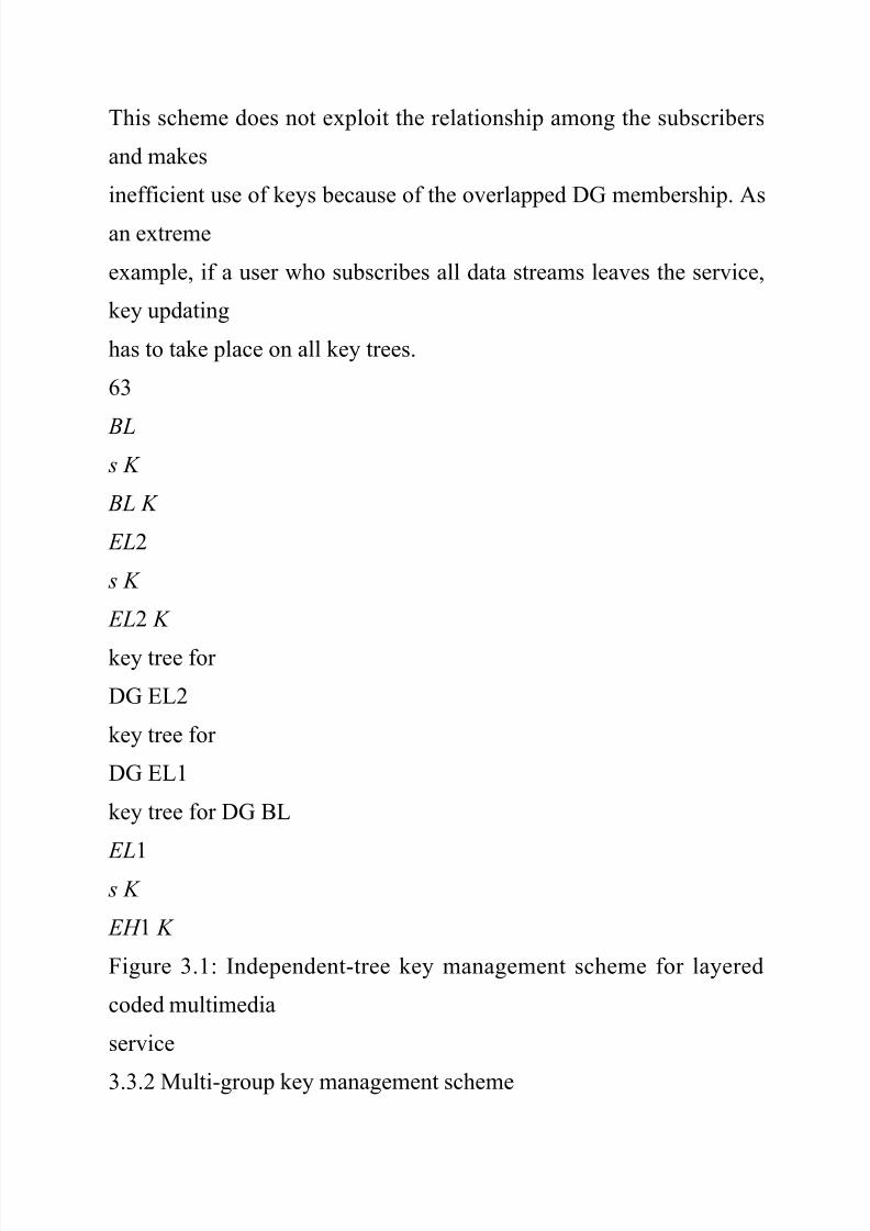
8/14/2019 Multi User Security
http://slidepdf.com/reader/full/multi-user-security 125/254
This scheme does not exploit the relationship among the subscribers
and makes
inefficient use of keys because of the overlapped DG membership. As
an extreme
example, if a user who subscribes all data streams leaves the service,
key updating
has to take place on all key trees.
63
BL s K
BL K
EL2
s K
EL2 K
key tree for
DG EL2
key tree for
DG EL1
key tree for DG BL
EL1
s K
EH 1 K
Figure 3.1: Independent-tree key management scheme for layered
coded multimedia
service
3.3.2 Multi-group key management scheme
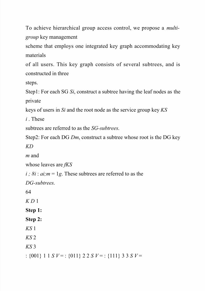
8/14/2019 Multi User Security
http://slidepdf.com/reader/full/multi-user-security 126/254
To achieve hierarchical group access control, we propose a multi-
group key management
scheme that employs one integrated key graph accommodating key
materials
of all users. This key graph consists of several subtrees, and is
constructed in three
steps.
Step1: For each SG Si, construct a subtree having the leaf nodes as the
privatekeys of users in Si and the root node as the service group key KS
i . These
subtrees are referred to as the SG-subtrees.
Step2: For each DG Dm, construct a subtree whose root is the DG key
KD
m and
whose leaves are fKS
i ; 8i : ai;m = 1 g . These subtrees are referred to as the
DG-subtrees.
64
K D 1
Step 1:
Step 2:
KS 1
KS 2
KS 3
: {001} 1 1 S V = : {011} 2 2 S V = : {111} 3 3 S V =

8/14/2019 Multi User Security
http://slidepdf.com/reader/full/multi-user-security 127/254
KS 3
KS 2
KS 3
KS 2
KS 3
KS 1
K D2
K D 3
1 SK 2 SK 3 SK Step 3:
KS 1
KS 2
KS 3
: {001} 1 1 S V = : {011} 2 2 S V = : {111} 3 3 S V =
K D 1
K D2
( ) 3
K D
1 SK 2 SK 3 SK
K 11-12
1 2 3 4 5 6 7 8 9 10 11 12
K 1-2 3-4 K 5-6 K 7-8 K 9-10 K
Figure 3.2: Multi-group key management graph construction
65
Step3: Generate the key graph by connecting the leaves of the DG-
subtrees and

8/14/2019 Multi User Security
http://slidepdf.com/reader/full/multi-user-security 128/254
roots of SG-subtrees.
This 3-step procedure is illustrated in Figure 3.2 for the services
containing 3 layers
and having 4 users in each SG. Some duplicated structures may
appear on DGsubtrees,
and they can be merged to reduce the number of keys on the key
graph.
In the example shown in Figure 3.2, KS
3 and KD3 , which are on the same line, are
merged. The DG-subtrees of D2 and D1 have the same structure that
connect KS
2
and KS
3 . Thus, the parent node of KS
2 and KS
3 on DG-subtree of D2 is merged
with KD
2 .
This multi-group key graph can also be interpreted as M overlapped
key trees,
each of which has KD
m as the root and the users in DG Dm as the leaves. Obviously,
these M key trees can be used in the independent-tree scheme. This
reveals the
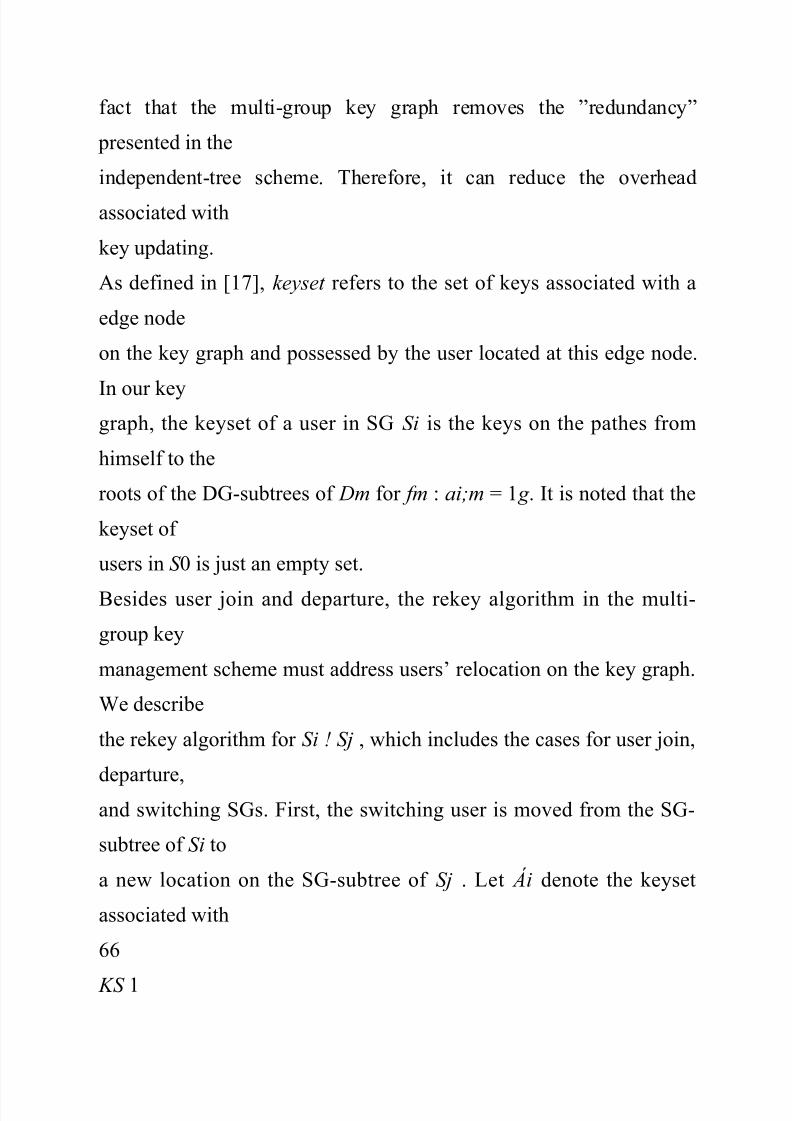
8/14/2019 Multi User Security
http://slidepdf.com/reader/full/multi-user-security 129/254
fact that the multi-group key graph removes the ”redundancy”
presented in the
independent-tree scheme. Therefore, it can reduce the overhead
associated with
key updating.
As defined in [17], keyset refers to the set of keys associated with a
edge node
on the key graph and possessed by the user located at this edge node.
In our keygraph, the keyset of a user in SG Si is the keys on the pathes from
himself to the
roots of the DG-subtrees of Dm for fm : ai;m = 1 g . It is noted that the
keyset of
users in S 0 is just an empty set.
Besides user join and departure, the rekey algorithm in the multi-
group key
management scheme must address users’ relocation on the key graph.
We describe
the rekey algorithm for Si ! Sj , which includes the cases for user join,
departure,
and switching SGs. First, the switching user is moved from the SG-
subtree of Si to
a new location on the SG-subtree of Sj . Let Ái denote the keyset
associated with
66
KS 1

8/14/2019 Multi User Security
http://slidepdf.com/reader/full/multi-user-security 130/254
KS 2
KS 3
K D 1
K D2
( ) 3
K D
1 SK 2 SK 3 SK
K 11-12
1 2 3 5 67
9 10 11 12
K 1-2 3-4 K 5-6 K 9-10 K
4 8
: keyset of the new position
: keyset of the previous position
2
1
f
f
4-8 K
Figure 3.3: User relocation on the key graph
the user’s previous position, and Áj denote the keyset associated with
the user’s
new position. Then,
² the KDC updates the keys in Ái \ Áj using one-way functions, similar
as the

8/14/2019 Multi User Security
http://slidepdf.com/reader/full/multi-user-security 131/254
procedure for user join in [18],
² and, the KDC generates new versions of the keys in Ái \ Áj and
distributes
these new keys encrypted by their children node keys from bottom to
up,
similar as the procedure for user departure in [18].
We illustrate this rekey algorithm through an example. Let user 8
switches from
SG S 2 to S 1 (see Figure 3.3). On the SG-subtree of S 1, the leaf nodeassociated
with user 4 is split to accommodate user 8. Then, user 4 and 8 will
share a
new KEK, denoted by K 4¡8. On the SG-subtree of S 2, user 7 will be
moved up
and occupy the node that is previously associated with K 7¡8. In this
case, Á 2 is
fK 7¡8;KS
2 ;KD
2 ; SK 2;KD
1 ; SK 1 g and Á 1 is fK 4¡8;K 3¡4;KS
1 ;KD
1 ; SK 1 g .
Let the notation xnew represent the new version of key x, fygx
represent the
key y encrypted by key x, and uk represent the private key of user k .
Each key is

8/14/2019 Multi User Security
http://slidepdf.com/reader/full/multi-user-security 132/254

8/14/2019 Multi User Security
http://slidepdf.com/reader/full/multi-user-security 133/254
2 gu7
fKD;new
2 gKS;new
2
; fKD;new
2 gKS
3
; fSKnew
2 gKD;new2
In this case, the rekeying message size is 7.
It is noted that Ái \Áj may contain the new KEKs that are created for
accommodating
the switching user. These new KEKs are encrypted by users’ private
keys and distributed through rekeying messages. In addition, Ái \ Áj
may contain
KEKs that do not exist any more after the relocation of the switching
user.
Obviously, these keys are discarded.
3.4 Performance Measures and Analysis
Communication, computation and storage overhead associated with
key updating
are major performance criteria for key management schemes [3, 4,
17]. In the
hierarchical access control scenario, we define the performance
measures as:

8/14/2019 Multi User Security
http://slidepdf.com/reader/full/multi-user-security 134/254
² Storage overhead at the KDC : denoted by RKDC and defined as the
expected
number of keys stored at the KDC.
68
² Rekey overhead at the KDC : denoted by MKDC and defined as the
expected
amount of rekeying messages transmitted by the KDC.
² Storage overhead of users: denoted by Ru2Si and defined as the
expectednumber of keys stored by the users in SG Si.
² Rekey overhead of users: denoted by Mu2Si and defined as the
expected
amount of rekeying messages received by the users in SG Si.
Here, RKDC and Ru2Si describe the storage overhead, while MKDC
and Mu2Si
reflect the usage of communication and computation resources.
3.4.1 Storage overhead
We first consider the storage overhead of a single key tree. Similar to
most key
management schemes [3, 4, 16–18], the key tree investigated in this
work is fully
loaded and maintained as balanced as possible by putting the joining
users on the
shortest branches.
Let fd (n) denote the length of the branches and rd (n) denote the total
number

8/14/2019 Multi User Security
http://slidepdf.com/reader/full/multi-user-security 135/254
of keys on the key tree when the key tree has degree d and
accommodates n users.
Since the key tree is balanced, fd (n) is either L0 or L0 + 1, where L0 =
blogd nc.
Particularly,
² the number of users who are on the branches with length L0 is dL0
¡dn¡dL0
d¡1 e;
² and, the number of users who are on the branches with length L0 + 1is
n ¡ dL0 + dn¡dL0
d¡1 e:
Thus, the total number of keys on this key tree is calculated as:
rd (n) = n + 1 +
dL0 ¡ 1
d ¡ 1
+ d
n ¡ dL0
d ¡ 1
e: (3.2)
69
Using the fact that n¡dL0
d¡1 · dn¡dL0
d¡1 e < n¡dL0
d¡1 + 1, we have
dE [n] ¡ 1

8/14/2019 Multi User Security
http://slidepdf.com/reader/full/multi-user-security 136/254
d ¡ 1
+ 1 · E [rd (n)] <
dE [n] ¡ 1
d ¡ 1
+ 2; (3.3)
where the expectation, E [:], is taken over the distribution of n( Dm)
and the length
of the branches on the key trees. The left-hand-side equality is
achieved whenlogd (n) is an integer. In addition, since logd (n) is a concave function
andblogd nc ·
logd n, it is clear that
E [ fd (n)] · E [logd n] + 1 · logd E [n] + 1: (3.4)
With (3.3) and (3.4), we are ready to analyze the storage overhead.
When
using the separate key trees (i.e. independent-tree scheme), the KDC
stores all
keys on total M key trees, and users in Si store subsets of keys on the
key trees
that are associated with Dm, for fm : t 0
m = 1 g . Thus,
Rind
KDC =
M X
m=1
E [rd (n( Dm))] ; (3.5)

8/14/2019 Multi User Security
http://slidepdf.com/reader/full/multi-user-security 137/254
Rind
u2Si =
M X
m=1
ai;m ( E [ fd (n( Dm))] + 1) : (3.6)
In the multi-group key management scheme, the DG-subtree of Dm
has cm =
P
i ai;m leaf nodes. Before removing the redundancy on DG-subtrees,there are
in total
PM
m=1 rd (cm) keys on DG-subtrees. Also, the total number of keys on
the SG-subtrees is
P I
i=1 rd (n(Si)). Merging duplicated structures of DG-subtrees
can future reduce the number of keys on the key graph. Therefore, the
storage
overhead at the KDC is
Rmg
KDC ·
X I
i=1
E [rd (n(Si))] +
M X
m=1

8/14/2019 Multi User Security
http://slidepdf.com/reader/full/multi-user-security 138/254
E [rd (cm)] : (3.7)
A user in SG Si stores fd (n(Si)) keys on the SG-subtree and up to
PM
m=1 ai;m( fd (cm)+
1) keys on the DG-subtrees. Therefore, the users’ storage overhead of
the multi-
70
group scheme is:
Rmg u2Si
· E [ fd (n(Si))] +
M X
m=1
ai;m( E [ fd (cm)] + 1): (3.8)
We will demonstrate the storage overhead of the independent-tree and
the
multi-group key management in the applications containing multiple
layers, as
described in Example 1 in Section 3.2.1. In this case, ai;m = 1 for m ·
i and
ai;m = 0 for m > i. We also assume that each layer contains the same
amount of
users, denoted by n(Si) = n0. Thus, n( Dm) = (M ¡ m + 1)n0. Using
(3.6) and
(3.8), the users’ storage overhead is calculated as:
Rind
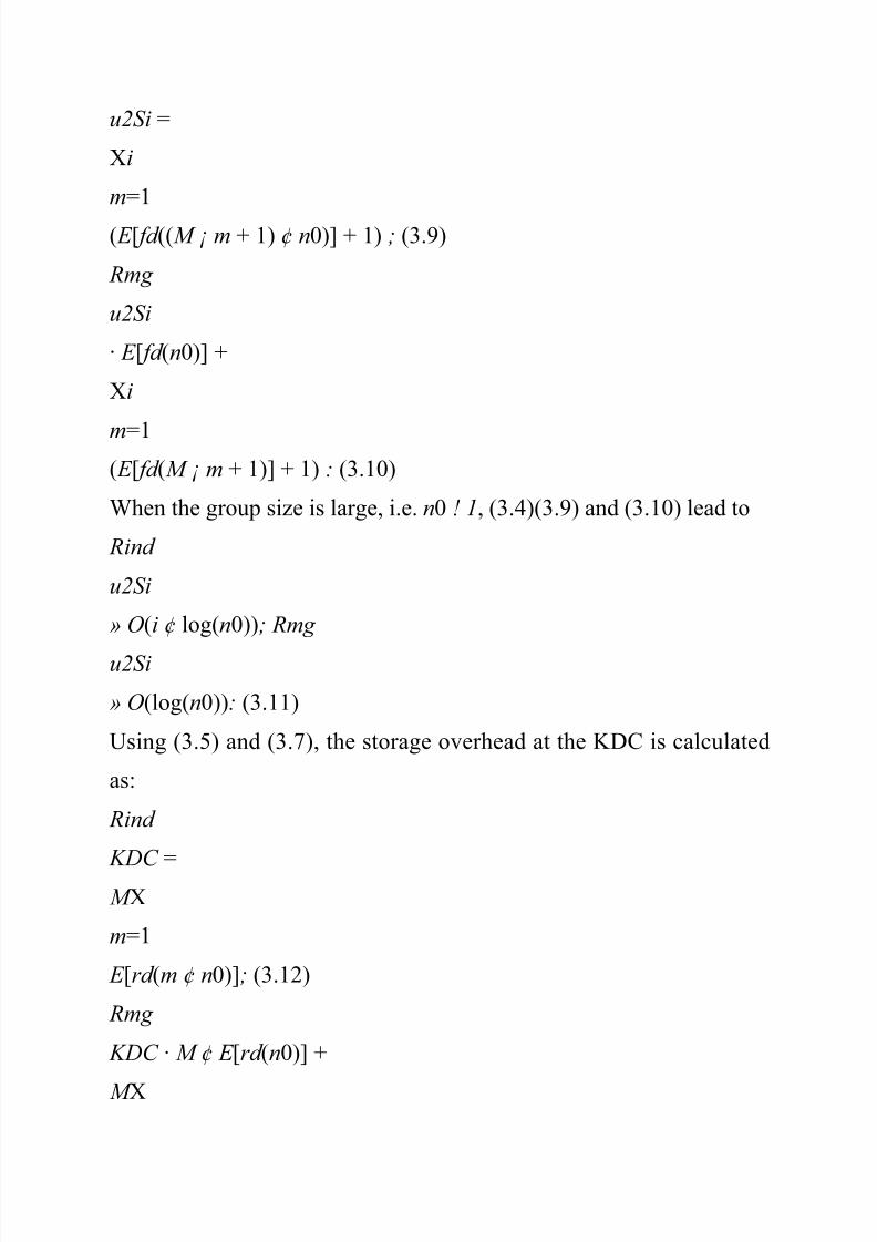
8/14/2019 Multi User Security
http://slidepdf.com/reader/full/multi-user-security 139/254

8/14/2019 Multi User Security
http://slidepdf.com/reader/full/multi-user-security 140/254
m=1
E [rd (m)]: (3.13)
From (3.3), it is seen that limn!1 rd (n) = d
d¡1n. Therefore,
Rind
KDC » O(
d
d ¡ 1
M (M + 1)2
n0); (3.14)
Rmg
KDC » O(
d
d ¡ 1
M ¢ n0): (3.15)
By using the integrated key graph instead of the separate key trees,
the multigroup
key management scheme reduces the storage overhead of both the
KDC and
71
the users. As indicated in (3.14) and (3.15), the storage advantage of
the proposed
scheme becomes larger when the system contains more SGs, i.e.
requiring more

8/14/2019 Multi User Security
http://slidepdf.com/reader/full/multi-user-security 141/254
levels of access control. The proposed scheme in fact scales better
when the number
of layers (M) increases.
3.4.2 Rekey overhead
In this section, we calculate the amount of rekeying messages
transmitted by the
KDC when one user switches from Si to Sj , denoted by Ci;j . It is
noted that the
rekey overhead, MKDC and Mu2Si , can be calculated from Ci;j , aslong as the users’
statistical joining/leaving/switching model is given.
Switching from Si to Sj is equivalent to adding the subscription to the
DG
fDm; 8m : ai;m = 0 and aj;m = 1 g and dropping the subscription to
the DG
fDm; 8m : ai;m = 1 and aj;m = 0 g . When using the tree-based key
management
schemes, the rekeying message size is calculated as:
Cind
ij =
M X
m=1
max(ai;m ¡ aj;m; 0) ¢ (d ¢ fd (n( Dm))) : (3.16)
We can see that the term (max(ai;m ¡aj;m; 0)) equals to 1 only when
ai;m = 1 and

8/14/2019 Multi User Security
http://slidepdf.com/reader/full/multi-user-security 142/254
aj;m = 0. When this term equals to 1, d¢fd (n( Dm) rekeying messages
are necessary
to update keys on the key tree associated with the DG Dm.
In the multi-group key management scheme, when a user switches
from Si to
Sj and i 6 = j,
² The amount of messages that update the keys on the SG-subtree of
Si is up
to (d ¢ fd (n(Si)) ¡ 1).² The amount of messages that convey the KEK created for
accommodating
the switching/join user on the SG-subtree of Sj is always less than 2.
72
² If this user drops the subscription of the DG Dm, i.e.
(max(ai;m¡aj;m; 0)) =
1, the amount of rekeying messages that update keys on the DG-
subtree of
Dm is up to (d ¢ fd (cm) + 1).
² If this user remains the subscription of the DG Dm, i.e. ai;m = aj;m
= 1, we
need up to (d ¢ fd (cm)) rekeying messages to update keys on the DG-
subtree
of Dm.
Therefore, when using the multi-group scheme and i 6 = j, we have
Cmg
ij ·

8/14/2019 Multi User Security
http://slidepdf.com/reader/full/multi-user-security 143/254
PM
m=1 (max(ai;m ¡ aj;m; 0) ¢ (d ¢ fd (cm) + 1)
+ ai;maj;md ¢ fd (cm)) + d ¢ fd (n(Si)) + 1; (3.17)
Similar as in Section 3.4.1, we analyze the rekey overhead in a multi-
layer
scenario with n(Si) = n0. In this case, the rekeying message size for
one user
departure, i.e. Sj ! S 0, is computed from (3.16) and (3.17) as:
Cind 0 j =
X j
m=1
d ¢ E [ fd ((M ¡ m + 1)n0)]; (3.18)
Cmg
0 j · d ¢ E [ fd (n0)] + 1 +
X j
m=1
(d ¢ E [ fd (M ¡ m + 1)] + 1) :
When n0 ! 1, we can see that
Cind
0 j » O(i ¢ d ¢ log(n0)); Cmg
0 j » O(d ¢ log(n0)): (3.19)
The comprehensive comparison between the proposed scheme and the
independenttree
scheme will be presented in Section 3.5.
3.5 Simulations and Performance Comparison

8/14/2019 Multi User Security
http://slidepdf.com/reader/full/multi-user-security 144/254
In this section, the proposed multi-group key management scheme is
compared with
the existing tree-based key management schemes in various
application scenarios.
73
3.5.1 Statistical dynamic membership model
In [50] [51], it has been shown that the users’ arrival process and
membership
duration of MBone multicast sessions can be modelled by Poissonand exponential
distribution respectively, in a short period of time. In this work, we
use this Poisson
arrival and exponential distribution duration model, and assume that
when a user
switches between SGs, the SG that he switches to depends only on his
current SG.
Therefore, the users’ statistical behavior can be described by an
embedded
Markov chain [53]. Particularly, there are a total of I + 1 states,
denoted by
f Si; i = 0; ¢ ¢ ¢ ; I . When a user is in the SG Si, he is in the state f Si.
After a user
enters state e Si, i.e. subscribes or switches to SG Si, this user stays at
state e Si for
time Ti, which is governed by an exponential random variable. When
time is up,

8/14/2019 Multi User Security
http://slidepdf.com/reader/full/multi-user-security 145/254
the user moves to state e Sj . The selection of e Sj only depends on the
current state
e Si and is not related to previous states.
In practice, it is usually not necessary to update keys immediately
after membership
changes. Many applications allow the join/departure users receive
limited
previous/future communications [39]. For example, in video
streaming applications,a joining user may receive a complete group-of-picture (GOP) [38]
although
partial of this GOP already been transmitted before his subscription.
Those situations
prefer batch rekeying [39] that postpones key updating such that the
rekeying
overhead is reduced by adding or removing several users altogether.
In this work, batch rekeying is implemented as updating keys
periodically.
The time between key updates is fixed and denoted by Bt . For the
users who
join/leave/switch SGs in the time interval ((k ¡ 1) Bt; kBt ], the key
updating will
take place at time kBt , where k is a positive integer. From the key
updating points
of view, with batch rekeying, we can prove that the previous
continuous Markov

8/14/2019 Multi User Security
http://slidepdf.com/reader/full/multi-user-security 146/254

8/14/2019 Multi User Security
http://slidepdf.com/reader/full/multi-user-security 147/254
P (n) = PN . The element at the ith row and jth column of P (n) is
denoted
by pij(n).
² The stationary state probability is a 1-by-( I + 1) vector, denoted by
¼ =
[¼0; ¼1; ¢ ¢ ¢ ; ¼I ].
In practice, most group applications have the following properties.
² p(n)0 j 6 = 0 for some positive finite n and for any j because users
should beable to subscribe to any SGs.
75
² p(n)i0 6 = 0 for some positive finite n and for any i because users
should be
able to leave from any SGs.
² pii > 0 because users can always stay in his current SG.
² The mean recurrence time [53] of the state e S 0 is finite because the
expected
time that a user stays in the group communication is finite.
Because of these properties, this Markov chain is irreducible,
aperiodic and positive
recurrent. As a result, the stationary state probability mass function
(pmf) exists
[53] and is the unique solution of
¼P = ¼; and
X
i

8/14/2019 Multi User Security
http://slidepdf.com/reader/full/multi-user-security 148/254
¼i = 1 : (3.20)
3.5.2 Performance with different group size
We first study the applications containing multiple layers (see
Example 1 in Section3.2.1)
where users in SG Si can access DG D1;D2; ¢ ¢ ¢ ;Di. In the
simulation, the transition
matrix is chosen as follows.
² Users join different SGs with the same probability, i.e. P 0 j = ®; 8j
> 0.² Users leave different SGs with the same probability, i.e. Pi0 = ¯; 8i
> 0.
² While a user is in the service, he adds/drops only one DG at a time,
i.e.
Pi;j = 0; 8i; j > 0 and ji ¡ jj > 1. Also, users switch between SGs with
the
same probability, i.e. Pi;j = °; 8i; j > 0 and ji ¡ jj = 1.
76
Thus, the transition matrix is described by only three variables. For
example,
the multi-layer service with M = 3 has the transition matrix as:
P =
2
66666666664
1 ¡ 3® ® ® ®
¯ 1 ¡ ¯ ¡ ° ° 0
¯ ° 1 ¡ ¯ ¡ 2° °

8/14/2019 Multi User Security
http://slidepdf.com/reader/full/multi-user-security 149/254
¯ 0 ° 1 ¡ ¯ ¡ °
3
77777777775
In all simulations, batch rekeying is applied and the key trees are
binary. The
initial state is chosen as the stationary state, i.e. Si contains N 0¼i
users at the
beginning of the service.
In Figure 3.5, 3.6, 3.7 and 3.8, the multi-group scheme and theindependenttree
scheme are compared for varying group size, N 0. The results are
averaged
over 300 realizations, and the number of layers is 4. In those
simulations, we chose
® = 0:005, ¯ = 0:01, and ° = 0:001.
Figure 3.5 shows that the storage overhead at the KDC, RKDC ,
increases linearly
with the group size. This result can be verified by (3.3)(3.5) and (3.7).
In
the case when M = 4, the multi-group scheme reduces RKDC by more
than 50%.
Figure 3.6 shows that the users’ storage overhead, Ru2Si , increases
linearly with
the logarithm of the group size. This can be verified by (3.9) and
(3.10). The users

8/14/2019 Multi User Security
http://slidepdf.com/reader/full/multi-user-security 150/254
who subscribe only one layer have the similar storage overhead in
both schemes.
For the uses who subscribe multiple layers, the multi-group scheme
results in less
storage overhead than the independent-tree scheme.
The KDC’s rekeying overhead, RKDC and the users’ rekey overhead,
Ru2Si are
shown in Figure 3.7 and 3.8, respectively. In both cases, the multi-
group schemereduces the rekey overhead by more than 50%.
77
0 500 1000 1500 2000 2500 3000
0
2000
4000
6000
8000
10000
Centralized −− Storage overhead at the KDC (4−layer)
Storage overhead at the KDC
N0 −− total number of potential users
Multi−group KM
Independent−tree KM
Figure 3.5: Storage overhead at the KDC
0 1000 2000 3000
0

8/14/2019 Multi User Security
http://slidepdf.com/reader/full/multi-user-security 151/254
5
10
15
20
25
30
35
40
Centralized −− Multi−group KM N0
Storage overhead
users in S1
users in S2
users in S3
users in S4
0 1000 2000 3000
0
5
10
15
20
25
30
35
40
Centralized −− Independent−tree KM

8/14/2019 Multi User Security
http://slidepdf.com/reader/full/multi-user-security 152/254
N0
Rekey overhead
Figure 3.6: Storage overhead at the users in each SG
0 500 1000 1500 2000 2500 3000
0
100
200
300
400500
600
Centralized −− Rekey overhead at the KDC (4−layer)
N0 −− total number of potential users
Rekey overhead at the KDC
Multi−group KM
Independent−tree KM
Figure 3.7: Rekey overhead at the KDC
78
0 1000 2000 3000
0
100
200
300
400
500
600

8/14/2019 Multi User Security
http://slidepdf.com/reader/full/multi-user-security 153/254
Centralized −− Multi−group KM
N0
Rekey overhead
users in S1
users in S2
users in S3
users in S4
0 1000 2000 3000
0100
200
300
400
500
600
Centralized −− Independent−tree KM
N0
Rekey overhead
Figure 3.8: Rekey overhead at the users in each SG
3.5.3 Scalability
Next, we change the number of layers (M) while maintaining roughly
the same
number of users in the service by choosing the join probability ® as
0:02=M . The
values of ¯ and ° are the same as those in Section 3.5.2.

8/14/2019 Multi User Security
http://slidepdf.com/reader/full/multi-user-security 154/254
Figure 3.9(a) and Figure 3.10(a) show the storage and rekey overhead
at the
KDC, respectively. When M increases, the storage and rekey
overhead of the
multi-group scheme do not change much, while the overhead of the
independenttree
scheme increases linearly with M . It is clear that the multi-group
scheme
scales better when M increase. By removing the redundancy in DGmembership,
the scale of the key graph mainly depends on the group size, not the
number
of layers or services. On the other hand, by constructing M separate
key trees,
the independent-tree scheme requires larger storage and rekey
overhead when M
increases even when N 0 is fixed.
79
2 2.5 3 3.5 4 4.5 5 5.5 6 6.5 7
0
2
4
6
8
10

8/14/2019 Multi User Security
http://slidepdf.com/reader/full/multi-user-security 155/254
x 104 Storage overhead at KDC with different number of
SGs(N0=15000)
The number of layers (I)
Storage overhead at KDC
Multi−group KM: Rmg
KDC
Independent−tree KM: Rind
KDC
2 2.5 3 3.5 4 4.5 5 5.5 6 6.5 71
2
3
4
Ratio: Rind
KDC / Rmg
KDC
The number of layers (I)
Rind
KDC / Rmg
KDC
Figure 3.9: Storage overhead at the KDC with different number of
SGs
Figure 3.9(b) shows that the ratio between Rind
KDC and Rmg
KDC increases linearly

8/14/2019 Multi User Security
http://slidepdf.com/reader/full/multi-user-security 156/254
with M , which agrees with (3.14) and (3.15). Similarly, the ratio
between Mind
KDC
and Mmg
KDC increases linearly with M , as shown in Figure 3.10(b).
3.5.4 Performance with different transition probability
In the previous simulations, we set ° = 0:1¯ , which means that the
users are
more likely to leave the service than to switch SGs. Figure 3.11 showsthe rekey
overhead with different values of °. Remember that ° describes the
probability of
user switching between SGs. In this simulation, M = 4, N 0 = 1000,
and the values
of ® and ¯ are the same as those in the previous experiments.
When ° is very small, the multi-group scheme reduces the rekey
overhead by
about 50%, as we have shown in the previous simulations. When ° is
less than 2¯ ,
the advantage of the multi-group scheme decreases with the increase
of °. This
is because the multi-group scheme introduces larger rekey overhead
when users
switch SGs by simply subscribing more DGs. To see this, let a user
move from
80

8/14/2019 Multi User Security
http://slidepdf.com/reader/full/multi-user-security 157/254
2 2.5 3 3.5 4 4.5 5 5.5 6 6.5 7
1000
2000
3000
4000
5000
Comm. Overhead at KDC
Comm. overhead at KDC with different number of SGs(N0=15000)
the number of layers (I)Multi−group KM: Mmg
KDC
Independent−tree KM: Mind
KDC
2 2.5 3 3.5 4 4.5 5 5.5 6 6.5 7
1
2
3
4
Ratio: Mind
KDC / Mmg
KDC
the number of layers (I)
Mind
KDC / Mmg
KDC

8/14/2019 Multi User Security
http://slidepdf.com/reader/full/multi-user-security 158/254
Figure 3.10: Rekey overhead at the KDC with different number of
SGs
0 0.05 0.1 0.15 0.2 0.25 0.3 0.35 0.4 0.45
0
100
200
300
400
500600
700
800
Communication Overhead at KDC with different transition prob.
(N0=1000)
The switch probablity factor
Comm. overhead at DKC
Multi−group KM
Independent−tree KM
Figure 3.11: Rekey overhead at the KDC with different transition
probability
81
SG S 1 to SG S 2. When using the independent-tree scheme, this user
only needs
to be added to the key tree associated with the DG D2 and no
rekeying messages

8/14/2019 Multi User Security
http://slidepdf.com/reader/full/multi-user-security 159/254
are necessary. When using the multi-group scheme, we need to update
keys on
the SG-subtree of S 1 and the DG-subtree of D1. Therefore, the
performance gain
reduces when more users tend to switch SGs.
When ° continues to increase, however, the rekey overhead of the
multi-group
scheme decreases. Particularly, when ° = 0:45, which describes the
scenario whereusers are much more likely to switch SGs than to stay in the current
SG or leave
the service, the performance gain of the multi-group scheme is about
50% again.
This phenomena is due to the fact that the size of the SG-subtree is
greatly reduced
when a significant potion of users are switching away from this SG.
In this case,
removing a large potion of users from the key tree using batch
rekeying requires
less rekeying messages than just removing several users.
3.5.5 Simulation of multi-service applications
We also simulated the multi-service scenario illustrated in Example 2
(Section
3.2.1), which contains 3 DGs and 7 SGs. The users can subscribe any
combination

8/14/2019 Multi User Security
http://slidepdf.com/reader/full/multi-user-security 160/254
of DGs and switch to any SGs. Here, the transition matrix is 8 by 8,
with Pj0 =
0:01; 8j > 0 and Pi;j = 0:00017; 8i; j > 0 and i 6 = j. N 0 is fixed to be
1500. The
values of P 0i; 8i > 0, are adjusted such that the SGs contain varying
number of
users while (
P I
i=1 P 0i) is maintained to be the same.The horizontal axis in Figure 3.12 is the ratio between the number of
users
subscribing more than one DGs and the number of users subscribing
only one DG.
Larger is this ratio, more overlap is in DG membership. Figure 3.12
shows that the
advantages of the multi-group scheme is larger when more users
subscribe multiple
82
0 0.5 1 1.5 2 2.5 3 3.5 4 4.5
120
140
160
180
200
220
240

8/14/2019 Multi User Security
http://slidepdf.com/reader/full/multi-user-security 161/254
# of users subscribing >1 DGs / # of users subscribing 1 DG
Centralized −− Rekey overhead at the KDC with unevenly loaded
SGs (multi−service)
Rekey overhead at the KDC
Multi−group KM
Independent−tree KM
Figure 3.12: Rekey overhead at the KDC with unevenly loaded SGs
in multi-service
applicationsDGs.
3.6 Contributory Multi-group Key Management
The multi-group key management schemes can be extended to the
contributory
environment by using the same graph construction procedure
presented in Section
3.3.2. Similar as in the centralized environments, separate key trees
for each DG
must be constructed when using existing tree-based contributory
schemes [31–33],
and the multi-group contributory schemes maintains one integrated
key graph for
all users.
The key establishment protocols are straightforward extensions from
the existing
protocols in tree-based contributory schemes [31–33]. When users
join/leave/switch,

8/14/2019 Multi User Security
http://slidepdf.com/reader/full/multi-user-security 162/254
the set of keys that need to be recalculated is the same as that need to
be updated
83
0 500 1000 1500 2000 2500 3000
0
10
20
30
4050
# of round for establishment
N0 −− total number of potential users
Contributary −− Rekey overhead at key establishment
Multi−group KM
Independent−tree KM
Figure 3.13: The total number of rounds performed to establish the
group key
in the protocols presented in Section 3.3.2. The new keys are
recalculated by applying
the DH protocol between the users who are under the left child node
and
the users who are under the right child node from bottom to up.
For contributory key management schemes, the number of rounds is
usually
used to measure the communication, computation, and latency [60]
associated

8/14/2019 Multi User Security
http://slidepdf.com/reader/full/multi-user-security 163/254
with key establishment and updating [30–32].
With the same simulation setup as that in Section 3.5.2, the
performance of
the independent-tree and multi-group contributory key management
schemes are
compared for varying group size. Figure 3.13 shows the total number
of rounds
to establish the group key, which reflects the latency in key
establishment [60].Figure 3.14 shows the number of rounds performed by the users in
each SG, which
describes the users’ computation overhead. In each round, a user
performs two
modular exponentiations. With the same simulation setup as that in
Section 3.5.2,
Figure 3.15 shows the number of rounds for key updating for with
different number
of layers. Compared with the tree-based contributory schemes, the
multi-group
contributory scheme significantly reduces the computation and
latency associated
with key establishment and updating. The advantage of the multi-
group contributory
scheme is larger when M increases.
In this chapter, we designed a multi-group key management scheme
that achieves

8/14/2019 Multi User Security
http://slidepdf.com/reader/full/multi-user-security 164/254
84
0 1000 2000 3000
0
5
10
15
20
25
3035
40
Contributory −− Multi−group KM
N0
# of rounds to establish key
users in S1
users in S2
users in S3
users in S4
0 1000 2000 3000
0
5
10
15
20
25
30

8/14/2019 Multi User Security
http://slidepdf.com/reader/full/multi-user-security 165/254
35
40
Contributory −− Independent−tree KM
N0
# of rounds to establish key
Figure 3.14: The number of rounds performed by the users in each SG
for key
establishment
2 2.5 3 3.5 4 4.5 5 5.5 6 6.5 710
20
30
40
50
60
70
80
90
Contributary −− Rekey overhead for different number of
SGs/Layers(N0=15000)
The number of SGs/layers (I)
# of rounds need to update keys
Multi−group KM
Independent−tree KM
Figure 3.15: The number of rounds performed to establish the group
key with

8/14/2019 Multi User Security
http://slidepdf.com/reader/full/multi-user-security 166/254

8/14/2019 Multi User Security
http://slidepdf.com/reader/full/multi-user-security 167/254
In order to design better security protocols, it is necessary to look at
the security
system from an adversarial point-of-view. By aggressively inspecting
existing key
management protocols, we discovered a weakness that has been
overlooked during
the design phase. That is, key management can disclose group
dynamic information
(GDI) to both insiders and outsiders. In this work, the group dynamicinformation particularly refers to a set of functions as:
² N (t ): the number of users in the multicast group at time t .
² J (t 0; t 1): the number of users who join the service between time t 0
and t 1.
² L(t 0; t 1): the number of users who leave the service between time t 0
and t 1.
In many group communications, GDI is confidential and should not
be disclosed
to either valid group members or outsiders. Such group applications
widely exist in
87
commercial as well as military applications, as discussed in Section
1.4. However,
to acquire GDI by launching attacks on the key management schemes
can be
very simple as we will demonstrate. Instead of trying to break the
encryption or

8/14/2019 Multi User Security
http://slidepdf.com/reader/full/multi-user-security 168/254
compromise the key distribution center, the adversaries can subscribe
to the service
as regular users. In this case, they are referred to as the inside
attackers. As we
will show later in this chapter, inside attackers can obtain very
accurate estimation
of GDI by monitoring the messages conveying new key updating
information, i.e.
rekeying messages. Even if the adversaries cannot become validgroup members,
they still have the opportunities to steal GDI as outside attackers as
long as they
can observe the traffic and distinguish the rekeying messages and
other data.
In this chapter, we demonstrate that the key management schemes can
reveal
the GDI easily and propose a framework of protecting GDI by
introducing
anti-attack technologies to key management. In particular, the attack
strategies
and the anti-attack method for the centralized schemes are presented
in Section
4.2 and Section 4.3 respectively. In Section 4.4, the performance
criteria of the
proposed anti-attack method are derived and the optimization problem
is formulated.

8/14/2019 Multi User Security
http://slidepdf.com/reader/full/multi-user-security 169/254
Simulation results based on the user log data from real MBone
sessions are
shown in Section 4.5. The investigation on contributory key
management schemes
is presented in Section 4.6.
4.2 GDI Attacks on Centralized Key management
In centralized key management schemes there usually exists a
centralized server,
such as the service provider, who is trustful, well protected, and hasthe compu-
88
tation and storage ability to generate and distribute the decryption
keys [3]. In
this section, we investigate the attack strategies that aim to attack the
centralized
key management schemes for obtaining the dynamic group
information. Two
attack strategies for tree-based key management will be presented,
followed by a
discussion of vulnerability of other prevalent centralized key
management schemes.
We consider a popular tree-based centralized key management
scheme proposed
in [18], whose rekeying process has been shown in Section 4.2.3. In
brief, when a

8/14/2019 Multi User Security
http://slidepdf.com/reader/full/multi-user-security 170/254
user leaves the group, all the keys on the path from this user to the
root of the
key tree are updated by conveying a set of rekeying messages, that
have the basic
format as one key encrypted by another key. When a user joins the
group, all
existing users compute the new key using a one-way function upon
noticing the
increased revision numbers of keys. No additional rekeying messagesare necessary.
The rekeying procedure although has some differences, most tree-
based centralized
key management schemes [3, 4, 16–19] share two common
properties. First,
group members can distinguish the key updating process due to user
join and that
due to user departure. Second, rekeying message size is closely
related with the
group size. Due to these properties, the attackers can estimate J (t 0; t 1)
and L(t 0; t 1)
by examining the rekey processes, and estimate N (t ) directly from the
rekeying
messages size. Next, we illustrate these two types of attacks on the
tree-based key
management scheme presented in [18].
4.2.1 Attack A1: Estimation of the number of join/departure

8/14/2019 Multi User Security
http://slidepdf.com/reader/full/multi-user-security 171/254

8/14/2019 Multi User Security
http://slidepdf.com/reader/full/multi-user-security 172/254
used. When this attack is successful, N (t ) can be calculated from J (t 0;
t 1) and
L(t 0; t 1) as:
N (t 1) = N (t 0) + J (t 0; t 1) ¡ L(t 0; t 1): (4.1)
Even if the attacker do not know the initial value of the group size, he
obtains
the changing trend of the group size.
4.2.2 Attack AII: Estimation of group size from rekeying
message sizeBesides using (4.1), the group size N (t ) can also be estimated directly
from the
rekeying message size. We will derive a Maximum Likelihood
estimator for the
attackers and then demonstrate the effectiveness of this estimator
through simulations.
We assume that N (t ) does not change much within a short period of
time. In
this time period, there are W departure users who do not leave
simultaneously.
90
Thus, the attacker makes W observations of the rekeying message size
due to single
user departure, denoted by Msg = fm1;m2; ¢ ¢ ¢ ;mwg .
Similar to most key management schemes [3,4,16–18], the key tree
investigated

8/14/2019 Multi User Security
http://slidepdf.com/reader/full/multi-user-security 173/254
in this work is fully loaded and maintained as balanced as possible by
putting the
joining users on the shortest branches. In the worst-case scenario, the
attacker
knows this property and the degree of the key tree, denoted by d .
Then, the
attacker can calculate the depth of the branch where the ith leaving
user was
located before departure, denoted by Li. Without losing information,the observed
Msg is converted to fL1 = l 1;L2 = l 2; ¢ ¢ ¢ ;LW = lWg , where li =
dmi+1
d e. Then,
the Maximum Likelihood (ML) estimator is formulated as:
NML = arg max
n
ProbfL1 = l 1;L2 = l 2; ¢ ¢ ¢ ;LW = lWjN (t ) = ng: (4.2)
To solve (4.2), we introduce a set of new variables:
fSkgk = Lmin;Lmin+1;¢¢¢;Lmax, where
Sk is the number of users who are on the branches with length k ,
Lmax is the
length of the longest branches, and Lmin is the length of the shortest
branches. It
is obvious that
X
k

8/14/2019 Multi User Security
http://slidepdf.com/reader/full/multi-user-security 174/254
Sk = n: (4.3)
In addition, the length of the branches of a key tree must satisfy the
Kraft inequality
[54], i.e.
P
j dLmax¡bj · dLmax, where bj is the length of the branch on which the
user j stays and j = 1; 2; ¢ ¢ ¢ ; n. Thus, Sk , which equals to the
number of elements
in set fbj : bj = kg , must satisfyX
k
SkdLmax¡k · dLmax; (4.4)
It can be verified that the equality is achieved when all intermediate
nodes on the
key tree have d children nodes. When the key tree is balanced and
fully loaded, it
91
is reasonable to approximate (4.4) by
X
k
SkdLmax¡k = dLmax: (4.5)
We assume that the leaving users are uniformly distributed on the key
tree, and
the number of users in the system is much larger than the number of
leaving users,
i.e. N (t ) >> W . Then, the probability mass function (pmf) of Li is

8/14/2019 Multi User Security
http://slidepdf.com/reader/full/multi-user-security 175/254

8/14/2019 Multi User Security
http://slidepdf.com/reader/full/multi-user-security 176/254
W
P
k h(k )d¡k : (4.8)
This ML estimator was applied to simulated multicast services. As
suggested
in [50] [51], the user arrival process is modelled as poisson process,
and the service
duration is modelled as an exponential random variable. In Figure
4.1(a), 4.1(b),and 4.1(c), the estimated group size is obtained by using the estimator
in (4.8),
and compared with the true values of N (t ). These three plots are for
different
simulation settings. The entire service period is divided into four
sessions. The
model parameters, i.e. user arrival rate and average service time, are
fixed within
each session and vary in different sessions. In the ith session,
described by interval
92
0 500 1000 1500 2000 2500
0
20
40
60
80

8/14/2019 Multi User Security
http://slidepdf.com/reader/full/multi-user-security 177/254
group size N(t)
Time (min)
0 1000 2000 3000 4000 5000
100
200
300
400
500
group size N(t)0 1000 2000 3000 4000 5000
0
100
200
300
400
500
group size N(t)
0 1000 2000 3000 4000 5000
0
100
200
300
400
500
600
group size N(t)

8/14/2019 Multi User Security
http://slidepdf.com/reader/full/multi-user-security 178/254
Time (min)
real N(t)
estimated N
ML
(t)
Estimate N(t) using ML estimator
(a) (b)
(c) (d)
Figure 4.1: Performance of the ML estimator [ti¡1; ti), the user arrival rate is ¸i and the average service time is ¹i. In
all
three cases, [t 0; t 1; t 2; t 3; t 4] is chosen to be [0; 200; 1600; 3200;
5000] minutes, and
the initial group size is 0. In plot (a), [ ¸1; ¸2; ¸3; ¸4] = [0:5; 0:5; 0:5;
0:3]min¡1 and
[¹1; ¹2; ¹3; ¹4] = [1400; 800; 600; 400]min. In plot (b), [ ¸1; ¸2; ¸3; ¸4]
is chosen as
[0:1; 0:3; 0:2; 0:5]min¡1, and [¹1; ¹2; ¹3; ¹4] is chosen as [1500;
1500; 1000; 800]min.
In plot (c), [ ¸1; ¸2; ¸3; ¸4] is [0:3; 0:7; 0:1; 0:9]min¡1 and [¹1; ¹2; ¹3;
¹4] is chosen as
[1400; 800; 600; 400]min. In addition, Figure 4.1(d) demonstrates the
performance
of the ML estimator, when it was applied to a real MBone audio
session, CBC

8/14/2019 Multi User Security
http://slidepdf.com/reader/full/multi-user-security 179/254
Newsworld on-line test, starting on Oct. 29. 1996 and lasted for about
5 days [61].
In all four cases, the changing trend of the group size is well captured
by the
attacker. It is also observed that the estimated group size tends to be
larger than
the true N (t ), which is due to the approximation that we replace (4.5)
by (4.4).
Although not perfect, this estimator is effective in helping theattackers to achieve
many of their goals, such as analyzing audience behavior and
monitoring the group
93
size changes.
The inside attackers can launch both attack AI and AII. They obtain
J (t 0; t 1)
and L(t 0; t 1) using AI, and the initial value N (t 0) using AII. Then,
N (t ) can be
obtained by using either (4.1) or (4.8), or jointly.
It has been shown that the rekeying messages must be delivered
reliably and
in a timely manner in order to guarantee the quality of service [62].
Therefore,
it is possible that rekeying messages are treated differently from the
regular data

8/14/2019 Multi User Security
http://slidepdf.com/reader/full/multi-user-security 180/254

8/14/2019 Multi User Security
http://slidepdf.com/reader/full/multi-user-security 181/254

8/14/2019 Multi User Security
http://slidepdf.com/reader/full/multi-user-security 182/254

8/14/2019 Multi User Security
http://slidepdf.com/reader/full/multi-user-security 183/254
the trusted local security agents perform admission control and key
updating for
95
the subgroups. This architecture reduces the number of users affected
by key
updating due to membership changes. Since the key updating is
localized within
each subgroup, the attacker can only obtain the dynamic membership
informationof the subgroup that he belongs to.
The idea of clustering was introduced in [24] to achieve the efficiency
by localizing
the key updating. The group members are organized into a
hierarchical
clustering structure. The cluster leaders are selected from group
members and
perform partial key management. Since the cluster leaders establish
keys for the
cluster members through pair-wise key exchange [24], the cluster
members cannot
obtain GDI of their clusters. However, the cluster leaders naturally
obtain the
dynamic membership information of their cluster and all clusters
below by participating
key management. In [24], the cluster size is chosen from 3 to 15.
Therefore,

8/14/2019 Multi User Security
http://slidepdf.com/reader/full/multi-user-security 184/254
this key management scheme can be applied only when a large potion
of group
members are trusted to perform key management and obtain GDI.
In Chapter 2, we have presented a topology-matching key
management (TMKM)
scheme that reduced the communication overhead associated with key
updating by
matching the key tree with the network topology and localizing the
transmissionof the rekeying messages. In this scheme, group members receive
only the rekeying
messages that are useful for themselves and their neighbors. Thus,
they only
obtains the local GDI by using AI or AII type attacks.
As a summary, Table 4.1 lists various key management schemes and
their vulnerability
to AI and AII type attacks. We can see that the AII type attacks are
effective for stealing GDI or local GDI from many key management
schemes. Two
schemes, flat VersaKey [18] and the clustering [24], are resistant to
these attacks.
Their usage, however, are limited by the fact that they are either not
resistant to
96
Is attack AII Is Attack AI
Centralized Key Management Schemes Effective? Effective?

8/14/2019 Multi User Security
http://slidepdf.com/reader/full/multi-user-security 185/254

8/14/2019 Multi User Security
http://slidepdf.com/reader/full/multi-user-security 186/254
We have discussed two types of attacks that can steal GDI from
centralized key
management schemes. This discussion, however, does not cover all
aspects of the
97
key management schemes that can reveal group dynamic information.
For example,
the number of KEKs possessed by the inside attacker equals to the
depth of thekey tree and reveals at least the order of the group size. We can also
show that
the IDs of the keys reveal the structure of the key tree. Thus, new
attack methods
may emerge in the future. Therefore, we propose an anti-attack
framework that
is robust to various types of attacks and compatible with most
centralized key
management schemes.
We first introduce the concept of Batch Rekeying that plays an
important role
in our anti-attack technique. As proposed in [39], batch rekeying is to
postpone
the update of keys such that several users can be added to or removed
from the
key tree altogether. Compared with updating keys immediately after
each user

8/14/2019 Multi User Security
http://slidepdf.com/reader/full/multi-user-security 187/254
join or departure, batch rekeying reduces the communication
overhead at the expense
of allowing the joining/leaving user to access a small amount of
information
before/after his join/departure.
In this work, batch rekeying is implemented as periodic updating of
keys and
the time between key updates are fixed and denoted by Bt .
Particularly, the userswho join or leave the group in the time interval [(k ¡ 1) Bt; kBt ], are
added to
or removed from the key tree together at time kBt . Then, the notations
of GDI
functions are simplified as: J (k ) = J ((k ¡ 1) Bt; kBt ), L(k ) = L((k ¡ 1) Bt;
kBt ),
and N (k ) = N (kBt ).
Since the AI type attacks are effective only when users are added to or
removed
from the key tree individually, utilizing batch rekeying can fight
against the AI type
attacks. However, batch rekeying alone is not enough to fight against
the AII type
attacks. Figure 4.2 shows some simulation results for the batch
rekeying when Bt is
set to be 5 minutes. Simulation setup is similar to that in Section
4.2.2. The solid

8/14/2019 Multi User Security
http://slidepdf.com/reader/full/multi-user-security 188/254
98
0 1000 2000 3000
0
500
1000
1500
2000
2500
# of users(a)
N(k)
Na(k)
0 1000 2000 3000
0
10
20
30
40
50
60
70
# of users joining
(b)
J(k)
Ja(k)
0 1000 2000 3000

8/14/2019 Multi User Security
http://slidepdf.com/reader/full/multi-user-security 189/254
0
10
20
30
40
50
60
70
# of users leaving(c)
J(k)
Ja(k)
0 1000 2000 3000
0
100
200
300
400
500
600
rekey message size
(d)
for the real GDI
for the artificial GDI
Figure 4.2: The anti-attack scheme using phantom users and batch
rekeying

8/14/2019 Multi User Security
http://slidepdf.com/reader/full/multi-user-security 190/254
line in Figure 4.2(a), 4.2(b), 4.2(c), 4.2(d) represent the N (k ), J (k ),
L(k ) and
the rekeying message size, respectively. One can see that the rekeying
message
size is closely related to L(k ) and reflects the trend of N (k ). A large
amount of
information about N (k ) and L(k ) can be obtained by the attackers from
examining
the rekeying message size.Besides using batch rekeying, we propose to insert phantom users into
the
system. These phantom users, as well as their join and departure
behavior, are
created by the KDC in such a way that the combined effects of the
phantom users
and the real users lead to a new rekeying process, called observed
rekeying process,
which is observed by the attackers. An important goal is for the
system to produce
an observed rekeying process that reveals the least amount of
information about
the GDI.
99
Let Na(k ) denote the total number of the real and phantom users, and
Ja(k )

8/14/2019 Multi User Security
http://slidepdf.com/reader/full/multi-user-security 191/254
and La(k ) denote the total number of the real and phantom users who
join/leave
the service respectively. Na(t ), Ja(k ), and La(k ) are referred to as the
artificial
GDI . From the key management points of view, the phantom users are
treated
the same as the real users. They occupy leaf nodes on the key tree,
and they are
associated with a set of KEKs that are updated when they virtually join or leave
the group. Thus, the observed rekeying process only depends on the
artificial GDI.
We first consider choosing the artificial GDI as a set of constant
functions, that
is,
Ja(k ) = L0; La(k ) = L0; Na(k ) = N 0: (4.9)
By doing so, the observed rekeying process does not leak the
information about the
changing trend of the real GDI. However, the perfect flat artificial
GDI functions
in (4.9) may not be achievable. Since the real GDI functions are
random processes,
it is possible that the predetermined L0 and N 0 are not large enough
such that the
artificial GDI cannot be maintained as straight lines. For example,
when N (k ) >

8/14/2019 Multi User Security
http://slidepdf.com/reader/full/multi-user-security 192/254
N 0, Na(k ) cannot be the predetermined value N 0 because the number
of phantom
users must be non-negative. In fact, the artificial GDI functions must
satisfies four
requirements: (r1) Na(k ) ¸ N (k ), (r2) La(k ) ¸ L(k ), (r3) Ja(k ) ¸ J (k ), and
(r4)
Na(k ) = Na(k ¡ 1) + Ja(k ) ¡ La(k ). In this work, we choose the
artificial GDI
functions as: Na(k ) = max fN (k );N 0 g (4.10)
Ja(k ) = max fJ (k );L(k );L0 g (4.11)
La(k ) = Na(k ¡ 1) ¡ Na(k ) + Ja(k ) (4.12)
When N (k ) · N 0, L(k ) · L0, and J (k ) · L0, equation (4.10)-(4.12) are
equivalent
100
to (4.9). The artificial GDI functions in (4.10)-(4.12) obviously satisfy
requirement
(r1) (r3) and (r4). Next, we prove that the requirement (r2) is also
satisfied.
² When N (k ) > N 0, it follows that
La(k ) = Na(k ¡ 1) ¡ Na(k ) + Ja(k ) ¸ L(k ) = N (k ¡ 1) ¡ N (k ) + J (k );
using the fact that Na(k ¡ 1) ¸ N (k ¡ 1), Na(k ) = N (k ), and Ja(k ) ¸ J (k ).
² When N (k ) · N 0, one can see that
La(k ) ¸ Ja(k ) ¸ L(k );
using the fact that Na(k ¡ 1) ¸ N 0 and Ja(k ) ¸ L(k ).

8/14/2019 Multi User Security
http://slidepdf.com/reader/full/multi-user-security 193/254
It shall be noted that there are many other ways to choose the artificial
GDI
functions. The proposed anti-attack scheme supports any artificial
GDI functions
that satisfy the requirement (r1)-(r4).
Given the artificial GDI functions, the KDC creates phantom users
and performs
key management as follows.
(1) Determine N 0 and L0 based on the system requirements and theusers’ statistical
behavior. The criteria for selecting N 0 and L0 will be presented in
Section 4.4.
(2) Before the service starts, create N 0 phantom users and establish a
key tree
to accommodate them. Set index k = 1.
(3) While the service is not terminated, execute the following:
– Record user join and departure requests in the time period ((k ¡ 1) Bt ,
kBt ], and obtain J (k ) and L(k ). During this time, the current session
101
key is sent to the joining users such that they can start receiving the
multicast content without delay.
– At time kBt , the KDC creates Ja(k ) ¡ J (k ) phantom users joining the
service, and then selects La(k ) ¡ L(k ) phantom users in the current
system and makes them leave. Following the key updating procedure
presented in any existing key management schemes, the KDC updates

8/14/2019 Multi User Security
http://slidepdf.com/reader/full/multi-user-security 194/254
corresponding keys for real and phantom users’ join and departure.
The
number of total real and phantom users are maintained to be Na(k ).
– Set k = k + 1.
Figure 4.2(a), 4.2(b), and 4.2(c) illustrate the real GDI ( N (k ), L(k ),
J (k )) and
the artificial GDI ( Na(k ), La(k ), Ja(k )) for a simulated multicast
service. The
simulation results of communication overhead, i.e. the rekeyingmessage size, is
shown in Figure 4.2(d), where the solid line represents the case
without phantom
users and the dash line represents case when the proposed anti-attack
method
is applied. We can see that the observed process reveals very limited
information
about the real GDI. Not surprisingly, the communication overhead
increases, which
is a disadvantage of utilizing phantom users.
Utilizing phantom users and batch rekeying is not the only solution to
the
problem of GDI leakage. There are other techniques that can protect
GDI from one
or several attacks. For example, embedding rekeying messages into
the multicast

8/14/2019 Multi User Security
http://slidepdf.com/reader/full/multi-user-security 195/254
content [19] can prevent outside attackers to launch the AII type
attacks. Using
the same rekeying procedure for user join and departure is also a good
way to
prevent the AI type attacks. In addition, the KDC can generate faked
rekeying
messages to prevent the AII type attacks, which is different from the
proposed
anti-attack scheme where the key tree reserves slots for the phantomusers and all
102
rekeying messages have meanings.
Compared with other techniques, using phantom users and batch
rekeying has
two major advantages. First, the proposed anti-attack scheme resists
to a variety
of attacks. Since the real GDI are concealed before the rekeying
messages are
generated, the attackers only see the artificial GDI from the observed
rekeying
process unless they break the encryption or compromise the KDC.
Second, the
proposed scheme does not rely on specific rekeying algorithms and is
compatible
with existing key management schemes.
4.4 Performance Measure and Optimization
8/14/2019 Multi User Security
http://slidepdf.com/reader/full/multi-user-security 196/254
In this section, we define two performance criteria and evaluate the
performance of
the proposed anti-attack technique. The criteria are (a) the amount of
information
leaked to the attackers measured by mutual information, and (b) the
communication
overhead introduced by the phantom users. We study the tradeoff
between
these two metrics and provide a framework of choosing proper amount of phantom
users, described by the parameter L0 and N 0 in (4.10)-(4.12).
4.4.1 The leakage of GDI
We use mutual information to measure the leakage of the GDI, which
is independent
of the attack strategies adopted by the attackers and represents the
maximum
amount of information that the attackers can possibly obtain. Let T be
the total
number of key updating, that is, the service duration is TBt . Then, the
real GDI
is described by a set of random variables as
R = fN (1); ¢ ¢ ¢ ;N (T ); J (1); ¢ ¢ ¢ ; J (T );L(1); ¢ ¢ ¢ ;L(T ) g; (4.13)
103
and the artificial GDI is
A = fNa(1); ¢ ¢ ¢ ;Na(T ); Ja(1); ¢ ¢ ¢ ; Ja(T );La(1); ¢ ¢ ¢ ;La(T ) g:
(4.14)

8/14/2019 Multi User Security
http://slidepdf.com/reader/full/multi-user-security 197/254
The mutual information, I ( R; A), describes the reduction in the
uncertainty of the
real GDI (R) due to the knowledge of the artificial GDI (A) [54].
Therefore, the
leakage of the GDI can be measured by
I ( R; A) = H ( A) ¡ H ( AjR); (4.15)
where H (:) and H (:j:) denote the entropy and conditional entropy,
respectively.
Equation (4.10) - (4.12) indicate that the artificial GDI is a set of deterministic
functions of the real GDI. Thus, the conditional entropy in (4.15)
equals to zero,
i.e. H ( AjR) = 0. Since La(k ) is directly computed from Ja(k ), Na(k )
and Na(k¡1)
in (4.12), the terms La(1);La(2); ¢ ¢ ¢ ;La(T ) can be removed from
the expression of
the entropy of A, i.e. H ( A) = H ( Na(1); ¢ ¢ ¢ ;Na(T ); Ja(1); ¢ ¢ ¢ ;
Ja(T )). Then, the
upper bound of I ( R; A) is calculated as:
I ( R; A) = H ( Na(1); ¢ ¢ ¢ ;Na(T ); Ja(1); ¢ ¢ ¢ ; Ja(T ))
·
X
k
H ( Na(k )) +
X
k

8/14/2019 Multi User Security
http://slidepdf.com/reader/full/multi-user-security 198/254
H ( Ja(k )): (4.16)
The equality is achieved when fNa(k ); Ja(k ); k = 1; ¢ ¢ ¢ ; Tg are
mutually independent.
It is noted that the GDI at time kBt and the GDI at time (k + 1) Bt can
be
approximately independent when Bt is large and the group is high
dynamic. In
these cases, (4.16) provides a tight upper bound of I ( R; A).
We introduce pNk (n) and pNak (n) to denote the pmf of N (k ) and Na(k ), respectively.
From (4.10), one can see that
pNak (n) =
8>>>>>><
>>>>>>:
P N 0
x=0 pNk ( x); n = N 0
pNk (n); n > N 0
0; o:w:
104
Then,
H ( Na(k )) = ¡(1 ¡ ²k
N ) log(1 ¡ ²k
N ) ¡
1X
n= N 0+1
pNk (n) log pNk (n); (4.17)

8/14/2019 Multi User Security
http://slidepdf.com/reader/full/multi-user-security 199/254
where ²k
N = 1 ¡
P N 0
x=0 pNk ( x). Similarly, let pJk ( x), pJak ( j), and pLk ( y) denote the
pmf of J (k ), Ja(k ), and L(k ), respectively. We then have,
H ( Ja(k )) = ¡
X
j
pJak ( j) log pJak ( j); (4.18)and,
pJak ( j) =
8>>>>>><
>>>>>>:
(1 ¡ ²k
J )(1 ¡ ²k
L); j = L0
pJk ( j)
P j¡1
y=0 pLk ( y) + pLk ( j)
P j¡1
x=0 pJk ( x) + pJk ( j) pLk ( j); j > L0
0; o:w:
(4.19)
where ²k
J = 1 ¡
P L0

8/14/2019 Multi User Security
http://slidepdf.com/reader/full/multi-user-security 200/254
x=0 pJk ( x) and ²k
L = 1 ¡
P L0
y=0 pLk ( y). Given the pmf of the
real GDI functions, the upper bound of I ( R; A) is calculated from
(4.16)-(4.19).
Since the observed rekeying process is determined by the artificial
GDI, the mutual
information between the observed process and the real GDI is bounded by I ( R; A)
due to the data processing theory [54]. Therefore, I ( R; A) is the upper
bound of
the amount of information that can be possibly obtained by the
attackers.
From (4.10)-(4.12), one can see that the artificial GDI reveals the real
GDI
when N (k ) > N 0, L(k ) > L0, or J (k ) > L0. We define overflow
probability as
the probability that the artificial GDI cannot be straight lines, i.e. 1 ¡
mink (1 ¡
²k
N )(1 ¡ ²k
L)(1 ¡ ²k
J ). Besides the mutual information, overflow probability can be
a more visualized complementary measure for the leakage of the GDI.
When the

8/14/2019 Multi User Security
http://slidepdf.com/reader/full/multi-user-security 201/254

8/14/2019 Multi User Security
http://slidepdf.com/reader/full/multi-user-security 202/254
DX¡1
l =0
®l
#
=
DX¡1
l =0
E [®l ] (4.20)
We introduce the notation B(b; i; a), which is equivalent to theexpected number
of non-empty boxes when putting i items in b boxes with repetition
where each
box can have at most a items. The detailed calculation of B(b; i; a) is
provided in
the Appendix. We can show that
E [®l ] = d ¢ B(dl; L;
N
dl ); 0 · l · D ¡ 2; (4.21)
E [®D¡1] = (d ¡ 1)
X L
e L=1
Ã
s1
e L
!Ã
N ¡ s1

8/14/2019 Multi User Security
http://slidepdf.com/reader/full/multi-user-security 203/254
L ¡ e L
!.Ã
N
L
!
B( s1; e L; d ) (4.22)
Using the fact that d i
ae · B(b; i; a) · min(b; i) (see Appendix), we can derive the
upper bound of the M ( L;N; d ) as:M ( L;N; d ) · dL logd ( N ): (4.23)
This upper bound indicates that the communication overhead
increases linearly
with the number of departure users and with the logarithm of the
group size.
106
Let Cr and Ca be the average communication overhead for rekey
process based
on real GDI and the artificial GDI, respectively. Then, the extra
communication
overhead introduced by the proposed anti-attack technique is:
Ca ¡ Cr =
1
T
XT
k =1
M ( La(k );Na(k ); d ) ¡

8/14/2019 Multi User Security
http://slidepdf.com/reader/full/multi-user-security 204/254
1
T
XT
k =1
M ( L(k );N (k ); d ): (4.24)
When the overflow probability is small, (4.24) can be approximated
by:
Ca ¡ Cr ¼ M ( L0;N 0; d ) ¡
1T
XT
k =1
M ( L(k );N (k ); d ): (4.25)
4.4.3 System optimization
From the system design points of view, parameter L0 and N 0 should
be chosen such
that the leakage of the GDI is minimized while the extra
communication overhead
do not exceed certain requirements. When the overflow probability is
small, the
optimization problem is formulated as:
min
N 0;L0
X
k
H ( Na(k )) +

8/14/2019 Multi User Security
http://slidepdf.com/reader/full/multi-user-security 205/254
X
k
H ( Ja(k )) (4.26)
subject to:
M ( L0;N 0; d ) · ¯; (4.27)
where ¯ is the maximum allowed communication overhead per key
updating. We
can show that H ( Na(k )) in (4.18) is monotonous non-increasing with
N 0; H ( Ja(k ))in (4.17) is monotonous non-increasing with L0; and the
communication overhead
M ( L0;N 0; d ) in (4.20) is non-decreasing with L0 and N 0. Therefore,
the optimization
problem is simplified as:
min
L0
Ã
X
k
H ( Na(k )) +
X
k
H ( Ja(k ))
!¯¯¯
N 0=M¡1(¯ ) jL0;d ;
(4.28)

8/14/2019 Multi User Security
http://slidepdf.com/reader/full/multi-user-security 206/254
107
0 1000 2000 3000 4000 5000 6000 7000 8000
0
20
40
60
N(k)
Group Dynamic Information of the CBC Newsworld On−Line Test
on 10/29/19960 1000 2000 3000 4000 5000 6000 7000 8000
0
5
10
15
J(k)
0 1000 2000 3000 4000 5000 6000 7000 8000
0
5
10
15
20
L(k)
Time (minute)
Figure 4.3: The GDI of a long audio session in MBone
where M¡1(¯ ) jL0;d is the largest value of N 0 that satieties (4.27) with
given L0 and

8/14/2019 Multi User Security
http://slidepdf.com/reader/full/multi-user-security 207/254
d . Fortunately, the number of departure users between two key
updates is usually
not a large number in practice. Thus, the searching space for
parameter L0 is not
large and this optimization problem can be solved by full search.
4.5 Simulations of the anti-attack scheme
Mlisten1, a tool developed at Georgia Institute of Technology, can
collect the
join/leave time for the multicast group members in MBone [50]sessions. Using
this tool, the characteristics of the membership dynamics of MBone
multicast
sessions has been studied in [50] [51].
The proposed anti-attack scheme is applied to the data collected in
1996 [61].
1available at www.cc.gatech.edu/computing/Telecomm.mbone
108
5 0 15 10 25 20 30
20
40
60
80
100
0
10
20

8/14/2019 Multi User Security
http://slidepdf.com/reader/full/multi-user-security 208/254
30
40
50
60
70
80
L0
Leakage of the GDI vs. L0 and N0
N0Upper bound of GDI Leakage (I(R;A))
Figure 4.4: Upper bound of the GDI leakages
Particularly, we selected one audio session that started on Oct. 29th
and lasted
for about 5 days and 20 hours. Figure 4.3 shows the N (k ), L(k ) and
J (k ) of this
session, where the Bt is chosen to be 15 minutes.
It is suggested that the users statistical behavior, such as inter-arrival
and
membership durations, can be modelled by exponential distribution in
a short
period of time [50]. In the simulation, the entire service time is
divided into nonoverlapped
sections, as illustrated in Figure 4.3. The length of these sessions is set
to be 4 hours. To simplify the analysis, it is assumed that N (k ), L(k )
and J (k ) are

8/14/2019 Multi User Security
http://slidepdf.com/reader/full/multi-user-security 209/254
stationary and ergodic Poisson processes in each session. Then, we
can calculate
the GDI leakage using (4.16)-(4.19).
Figure 4.4 and Figure 4.5 demonstrate the upper bound of mutual
information
(see (4.16)) and the communication overhead M ( L0;N 0; d ) for
different values of L0
109
05
10
15
20
25
30
20
30
40
50
60
70
80
90
100
0
100

8/14/2019 Multi User Security
http://slidepdf.com/reader/full/multi-user-security 210/254
200
300
400
L0
Communication Overhead vs. L0 and N0
N0
Upper bound of Communication Overhead (M(L0,N0,d) )
Figure 4.5: Communication overhead M ( L0;N 0; d )
and N 0, respectively. We can see that communication overhead is anon-decreasing
function with L0 and N 0, while the GDI leakage is a non-increasing
function with
L0 and N 0. This verifies the argument in Section 4.4.
Figure 4.6 illustrates the solution of the optimization problem. Figure
4.6(a)
shows the maximum value of N 0 that satisfies the communication
overhead constraint
in (4.27) with fixed L0, i.e. N 0 = maxfN : M ( L0;N; d ) · ¯g , where ¯ is
chosen to be 50 in this example. As discussed in Section 4.4, the
optimal values
of L0 and N 0 must be on this curve. Therefore, the upper bound of the
GDI
leakage,
P
k H ( Na(k )) +
P

8/14/2019 Multi User Security
http://slidepdf.com/reader/full/multi-user-security 211/254
k H ( Ja(k )), is evaluated only at ( L0;N 0 = maxfN :
M ( L0;N; d ) · ¯g ), which is shown in Figure 4.6(b). The optimal values
of L0 and
N 0 are also marked.
Figure 4.7 shows the tradeoff between the communication overhead
and the GDI
110
0 2 4 6 8 10 12 14 16
100101
102
103
L0
The maximum N0 that satisfies the comm. overhead constrain, (b=50)
N0 = max {N : M(L0, N,d)} £ b
0 2 4 6 8 10 12 14 16
0
20
40
60
80
100
120
L0
Upper bound of GDI leakage vs L0
S H(Na(k)) + H(Ja(k))

8/14/2019 Multi User Security
http://slidepdf.com/reader/full/multi-user-security 212/254
(a)
(b) optimal Lo
optimal No
Figure 4.6: Illustration of selecting optimal parameters L0 and N 0.
leakage. This figure demonstrates the upper bound of the mutual
information as a
function of the communication overhead constraint, where the
parameters L0 and
N 0 have been optimized. This can help the system designer indetermining the
proper ¯ for the communication constraint in (4.27). When not using
phantom
users, the artificial process is identical to the real process and we have
I ( R; A) =
I ( R; R) = H ( R). In this case, this particular multicast session require
average 3.6
rekeying messages to be sent in every 15 minutes ( Bt = 15) and has
I ( R; A) ¼ 137.
Figure 4.7 shows that the proposed anti-attack scheme can reduces
I ( R; A) to 5:5
by increasing the communication overhead to 23:2 messages every 15
minutes. The
communication overhead Ca is significantly larger than Cr because a
large amount
of activities of the phantom users must be created. However, the
absolute value of

8/14/2019 Multi User Security
http://slidepdf.com/reader/full/multi-user-security 213/254
the Cr is still small compared with the multicast data throughput. On
the other
111
15 20 25 30 35 40 45 50 55
0
5
10
15
2025
30
35
40
Communication Overhead
GDI leakage
GDI leakage vs Communication Overhead for a non−active session
When not using phantom users
communication overhead : 3.6
leakage of GDI : 137
Figure 4.7: The GDI leakage versus communication overhead for a
real MBone
audio session
hand, the leakage of the group dynamic information is greatly
reduced.
It is important to note that this MBone audio session contains only up
to 60

8/14/2019 Multi User Security
http://slidepdf.com/reader/full/multi-user-security 214/254
users and represents the scenario where the group size is small and
group members
are not very active. Due to the lack of the experimental data for large
multicast
groups, we investigated a simulated multicast session with larger
group size and
more active group members. The simulation setup is the same as that
is used
for Figure 4.1(c) in Section 4.2, where the group size is about 500.When not
using phantom users, the KDC sends average 28.16 rekeying
messages in every
5 minutes ( Bt = 5), while the amount of information leaked to the
attackers,
H(R), is 249.2. The performance of the proposed anti-attack methods
is shown in
Figure 4.8. We can see that the GDI leakage can be reduced to 5 at the
expense of
increasing the communication overhead to 93 messages per 5
minutes. The relative
communication increase is smaller than that for the less active
sessions.
112
50 60 70 80 90 100 110 120
0
5

8/14/2019 Multi User Security
http://slidepdf.com/reader/full/multi-user-security 215/254
10
15
20
25
30
35
40
45
50Communication Overhead
GDI leakage
GDI leakage vs Communication Overhead for an active session
When not using phantom users:
communication overhead : 28.16
leakage of GDI: 249.2
Figure 4.8: The GDI leakage versus communication overhead for a
simulated multicast
session
4.6 Contributory Key Management Schemes
As we have discussed in the previous sections, group keys are
generated and distributed
by the key distribution center when centralized key management
schemes
are employed. In many scenarios, however, it is not preferred to rely
on a centralized

8/14/2019 Multi User Security
http://slidepdf.com/reader/full/multi-user-security 216/254
server that arbitrates the establishment of the group key. This might
occur
in applications where group members do not explicitly trust a single
entity, or
there are no servers or group members who have sufficient resources
to maintain,
generate and distribute keying information. Thus, the distributed
solution of the
key management problem has seen considerable attention [18, 25– 33].
The contributory key management schemes do not rely on centralized
servers.
Instead, every group member makes independent contribution and
participates the
process of group key establishment. The members’ personal keys are
not disclosed
113
to any other entities [28]. An important class of contributory key
management
schemes, such as [25–33], are inspired by the Diffie-Hellman (DH)
two-party key
exchange protocol [35], and are usually refereed to as the Diffie-
Hellman-like protocols.
Compared with the centralized schemes, the contributory schemes
have the

8/14/2019 Multi User Security
http://slidepdf.com/reader/full/multi-user-security 217/254
advantage of not putting full trust on a single entity and therefore do
not suffer
the problem of single-point-failure. However, their distributed nature
makes the
task of protecting the GDI very difficult. In this section, we
investigate the ways
that the group members acquire GDI from the Diffie-Hellman-like
key management
schemes and provide a brief discussion on preventing the leakage of GDI.
4.6.1 Fully and partially contributory key management schemes
We discuss two slightly different flavors of contributory key
agreement scheme:
fully contributory and partially contributory.
In the fully contributory schemes, all key agreement operations are
contributed
to every group member [29]. Since there is no dedicated group
manager, every
participant may perform admission control and other administrative
functions [29].
Thus, group members are naturally aware of the information about the
group
membership. In addition, group members are usually arranged in a
logical ring [25],
a logical chain [28–30], or a logical tree [31–33]. These logical
ring/chain/tree

8/14/2019 Multi User Security
http://slidepdf.com/reader/full/multi-user-security 218/254
structures describe the key establishment procedure, and must be
maintained and
updated by every member independently in the fully contributory
environment [31].
This, again, requires members to have knowledge of the initial group
membership as
well as the membership changes. Therefore, the fully contributory
schemes, whose
implementation relies on the members’ knowledge on dynamic groupmembership,
are not suitable for the multicast applications with confidential GDI.
114
In the partially contributory schemes, one group member takes on a
special
role and performs some operations in a centralized manner [28] [29].
This special
member is usually referred to as the group controller . The role of the
group controller
can be assigned to a fixed member or be handed over to other
members
when membership changes [29]. The group controller is different
from the KDC in
the centralized schemes because it does not hold the private keys of
other members
or generate the complete group key for other members. Instead, it may
perform

8/14/2019 Multi User Security
http://slidepdf.com/reader/full/multi-user-security 219/254
admission control and coordinate the process of the key formation.
The original
purpose of introducing group controller is to achieve efficient key
updating in the
case of user joining and departure [28]. In the context of protecting
GDI, the
partially contributory schemes make it possible to confine dynamic
membership
information to the group controllers while preventing other groupmembers from
accessing GDI. Although only a handful of contributory schemes [28–
32] suggest
using group controller, most of the schemes [25–27, 33] can work in
the partially
contributory manner. For contributory key management schemes, the
fundamental
rule for protecting GDI is that a group controller that is trusted to
handle GDI
shall perform admission control, maintain the logical key
ring/chain/tree structure
and coordinate the process of the key formation.
4.6.2 Vulnerability of popular contributory key management
schemes
Utilizing group controller is not a complete solution to the GDI
protection problem.

8/14/2019 Multi User Security
http://slidepdf.com/reader/full/multi-user-security 220/254
Next, we examine the Diffie-Hellman-like key management schemes
and demonstrate
various other opportunities for the insiders to acquire group dynamic
information.
115
The scheme presented in [25] is the earliest attempted to extend two-
party
Diffie-Hellman protocol to group scenario. This scheme, sometimes
referred to asING [30], arranges members in a logical ring and is executed in (n ¡
1) round,
where n is the group size. Therefore, every member obtains the group
size by
simply counting the number of rounds that he performed.
Similarly, the schemes presented in [26] and [27], referred to as the
STR and BD
respectively, also reveal the group size. Here, each member receives
the broadcast
messages from all other members, and therefore must know the
existence of other
group members.
In [31] [32] [33], logical tree structures are introduced to manage the
formation
of the group keys. In these schemes, each member performs L rounds
and holds L
8/14/2019 Multi User Security
http://slidepdf.com/reader/full/multi-user-security 221/254
subgroup keys, where L is the depth of the key tree. Since L is
proportional to the
logarithm of the group size, group members know at least the order of
the group
size.
Another important set of contributory key management schemes are
GDH.1,
GDH.2 and GDH.3 [28]. These schemes arrange group members in a
logical chainand accumulate the keying material by traversing group members one
by one. In
GDH.1/2, the kth member receive k or k +1 messages from the (k
¡1)th member.
Thus, the amount of the messages reveals information about the group
size. The
users who are closer to the end of the chain have more accurate
information about
the group size. GDH.3 is executed in four stages [28]. In the second
and the fourth
stage, the last user on the key chain broadcast n messages to the rest
of the group,
and n is the group size. In all three schemes, the group size
information is revealed
by the size of keying messages.
116
4.6.3 Prevention of GDI leakage
8/14/2019 Multi User Security
http://slidepdf.com/reader/full/multi-user-security 222/254
As discussed in Section 4.6.1 and 4.6.2, the contributory key
management schemes
are more vulnerable to GDI attacks than the centralized schemes.
Besides examining
rekeying message size as in the centralized schemes, the attackers can
also steal GDI through performing admission control, maintaining the
logical key
ring/chain/tree structure, and counting the number of rounds in the
contributorykey management schemes.
In general, we suggest using centralized key management schemes for
the applications
with confidential GDI. However, there are scenarios that centralized
schemes cannot be employed, such as when no trusted centralized
entities exist.
In these cases, we suggest using GDH.3, which has the strongest
centrality flavor
amongst contributory schemes. As discussed in Section 4.6.2, GDH.3
reveals group
size through the broadcast message size. Thus, the following
modifications must
be made.
² Selecting the group member at the end of the logical chain as the
group
controller, who performs admission control and coordinates the key
formation

8/14/2019 Multi User Security
http://slidepdf.com/reader/full/multi-user-security 223/254
such that a regular member only communications with his two
neighbors on
the key chain and the group controller in the key establishment
process.
² Replacing the broadcasting in the second and fourth stage [28] by
multiple
unicasting, which unfortunately increases the communication
overhead.
The modified GDH.3 prevents regular group members from obtainingthe information
on the group size, at the expenses of non-scalable communication
overhead.
In addition, anti-traffic-analysis techniques, such as in [64] [65], shall
be used to
prevent the GDI attacks from outsiders, which will not be discussed in
this work.
117
In this chapter, we raised the issues of the disclosure of dynamic
group membership
information through key management. We demonstrated that such a
new
security threat impacts various group communication applications.
We developed
attack strategies that could steal the GDI from key management. To
protect GDI,

8/14/2019 Multi User Security
http://slidepdf.com/reader/full/multi-user-security 224/254
an anti-attack framework was investigated, that involves utilizing
batch rekeying,
introducing phantom users, and analyzing the tradeoff between
communication
overhead and security.
118
Chapter 5
Conclusion and Future Work
This dissertation presented the design of network-specific andapplication specific
group key management schemes and investigated the problem of
protecting dynamic
group membership information in secure group communications.
In particular, we presented a method for designing the multicast key
management
tree in the mobile wireless environment. By matching the key
management
tree to the cellular network topology and localizing the delivery of
rekeying messages,
a significant reduction in the communication burden associated with
rekeying
was observed compared to trees that are independent of the topology.
We
designed a topology-matching key management tree that consists of
user-subtrees,

8/14/2019 Multi User Security
http://slidepdf.com/reader/full/multi-user-security 225/254
BS-subtrees and SH-subtrees. It was shown that the problem of
optimizing the
communication cost for the TMKM tree is separable and can be
solved by optimizing
each of those subtrees separately. The ALX tree structure, which
easily
adapts to changes in the number of users, was introduced to build
user-subtrees
and BS-subtrees. The performance of the ALX tree is very close tothe performance
lower bound for any fixed degree tree. The GSHD algorithm, which
considers the
network heterogeneity where the SHs administer areas with varying
network con-
119
ditions, was introduced to build the SH subtree. The performance of
the GSHD
algorithm is very close to the optimal and has better performance than
treating
SHs equally. Additionally, we addressed the consequences that user
mobility has
upon the TMKM tree, and presented an efficient handoff scheme to
reduce the
communication burden associated with rekeying. A popular user
joining/leaving

8/14/2019 Multi User Security
http://slidepdf.com/reader/full/multi-user-security 226/254
procedure was used to study the performance of the TMKM and
TIKM trees.
Both simulations and analysis were provided. For systems consisting
of only one
SH, simulations performed for different user-join rates and mobile
user speeds
show that the cost of the TMKM tree is approximately 33-45% of the
cost of the
TIKM tree, which indicates a reduction of 55-67% in the totalcommunication cost.
For systems consisting of multiple SHs, simulations were performed
for different
amounts of participating SHs, and indicated that the TMKM tree can
reduce the
communication burden by as much as 80%. In addition, both analysis
and simulations
indicate that the communication cost of the TMKM tree scales better
than
that of topology-independent trees as the number of participating SHs
increases.
While traditional group key management only provides the same
access privilege
to all group members, this dissertation presented a multi-group key
management
scheme that achieves hierarchical group access control in secure
group

8/14/2019 Multi User Security
http://slidepdf.com/reader/full/multi-user-security 227/254

8/14/2019 Multi User Security
http://slidepdf.com/reader/full/multi-user-security 228/254
require the mechanism to manage more levels of access control.
Besides scalability issues, a more fundamental concern of group key
management
is security. This dissertation raised the issues of the disclosure of
dynamic
group membership information through key management in secure
multicast communications.
Such a security concern has not been addressed in traditional key
management schemes. We demonstrated that the attackers cansuccessfully obtain
good estimates of the GDI from a large number of centralized and
contributory key
management schemes, and investigated the techniques of improving
or modifying
the existing key management schemes such that the GDI as well as
the multicast
content is protected. For the centralized key management schemes, we
developed
two effective attack strategies, which exploit the format and the size
of the rekeying
messages. To protect the GDI, we proposed the anti-attack technique
utilizing
batch rekeying and phantom users. This anti-attack technique reduces
the leakage
of the GDI and is fully compatible with the existing centralized key
management
8/14/2019 Multi User Security
http://slidepdf.com/reader/full/multi-user-security 229/254
schemes. We investigated the tradeoff between the communication
overhead and
the leakage of the GDI, and provided a framework for selecting the
proper amount
of phantom users. The proposed anti-attack technique was tested on
real MBone
user log data and simulated multicast sessions. We also demonstrated
the vulnerability
of the contributory key management schemes, where group memberscan
121
acquire the group size from performing admission control,
maintaining logical key
ring/chain/tree structure, counting the number of rounds and
measuring the number
of the key exchange messages. In the contributory environment, the
solution of
protecting GDI involves utilizing the group controller and modifying
the existing
GDH.3 key establishment protocol.
Based on the research results presented in this dissertation, there are
several
research directions that can be further investigated:
Fault-tolerant contributory key agreement
Besides the technologies that have been presented in this dissertation,
we plan

8/14/2019 Multi User Security
http://slidepdf.com/reader/full/multi-user-security 230/254
to incorporate the fault-tolerate features in the future design,
especially for contributory
key management. The existing contributory key management schemes
assume that users honestly perform the key agreement protocol. As a
result, they
perform poorly or not at all in the presence of malicious group
members who manipulate
the keying messages and aim to cause the key agreement process to
fails.To demonstrate this fact, we examine one of the most popular
schemes for distributed
key agreement, namely GDH.2. This scheme organizes the users in a
chain. Each user performs computation and passes some intermediate
values to
the next user. This stage of the scheme is referred to as upflow and
continues until
the computation and passing on of intermediate results has reached
the last user
at the end of the chain. Then, the direction of information flow is
reversed and the
scheme enters its downflow stage. The users once again perform
computation on
intermediate values and pass them on. During both upflow and
downflow stages,
malicious users have the opportunity to selectively sabotage the
intermediate results

8/14/2019 Multi User Security
http://slidepdf.com/reader/full/multi-user-security 231/254
calculated by the users that are ordered before them in the chain. At
the end
of the key agreement protocol, all users individually calculate the
group key. The
122
users, whom have been targeted by the malicious users, will have a
different key
from the rest of the group. In this case, no common group secret is
establishedfor securing group communication and the group key agreement
protocol fails. For
GDH.2, we can show that a malicious user can sabotage and remain
undetected
even after the key generation protocol is run many times with
different orderings
of the users. The failure of key agreement not only prevents secure
group communication,
but also causes extra use of computational and communication
resources
that are precious for wireless scenarios. All communication and
computation spent
on the key agreement is in vein since it is not possible to recover or
reuse any part
of previous group secret.
We believe that one of the largest problems with GDH.2 and any
scheme that

8/14/2019 Multi User Security
http://slidepdf.com/reader/full/multi-user-security 232/254
operates in a similar manner is the lack of verifying intermediate
steps. In order to
detect malicious users and recover from possible errors, our
preliminary investigation
suggests that distributed tree-based key agreement schemes, have the
potential
of detecting malicious users and allow for efficient recovery from key
establishment
failure. In tree-based key agreement schemes, the keys are generatedrecursively,
allowing us to integrate detection and error recovery in the key
generation process.
We propose to design a protocol that detects malicious behavior/error
by selectively
validating the intermediate results and achieves fast recovery by
reusing
validated intermediate keys. The idea is to solve the dispute locally
before it
affects the entire group. We will investigate the tradeoff between the
probability
of successful establishing the group key and the increased
communication and
computation cost due to the checking mechanism.
Topology-aware hierarchical access control with GDI protection
In this dissertation, we have addressed the topology-aware key
management,

8/14/2019 Multi User Security
http://slidepdf.com/reader/full/multi-user-security 233/254
123
hierarchical access control and GDI protection separately. In the
future, we plan
to develop a suite of key management design techniques that
incorporate all above
advanced technologies. For example, topology-match key
management has positive
influence on protecting GDI because the users may only obtain their
local GDIin TMKM scheme. In addition, the hierarchical key management
design may
also consider topology issues, when the access requirement is
correlated with the
physical locations of users.
More topics in wireless network security
Wireless communication has dramatically changed the way people
work and
interact. Unfortunately, the wireless era continues to be plagued by
insufficient
security. Key management solves the group access control problem,
but it is not
the complete solution of wireless network security problem. In
wireless networks,
the security weakness exists in every layer. In the future, we will
investigate secure

8/14/2019 Multi User Security
http://slidepdf.com/reader/full/multi-user-security 234/254
routing in ad hoc networks and securing resource allocation against
greedy users.
Secure routing protocols are the foundation of the dependability in ad
hoc
networks. Various attacks, such as black/gray hole, rushing attack,
blackmail,
wormhole, prevent good routes being discovered and cause denial-of-
service. We
would like to develop a set of mechanisms to secure against routingdisruptions.
For each node, the first mechanism is to launch a route traffic
observer to monitor
the behavior of each valid route in its route cache, and to collect the
packet
forwarding statistics submitted by the hops on the routes. Since
malicious nodes
may submit false report, for each node, the next mechanism is to keep
a cheating
record database for the other nodes. If a node is detected as dishonest,
future route
discovery should prevent this node from being on the route. The third
mechanism
is to use friendship (trust relationship) to speed up the malicious node
detection.
124

8/14/2019 Multi User Security
http://slidepdf.com/reader/full/multi-user-security 235/254
The fourth mechanism is to explore route diversity by discovering
multiple routes
to the destination, which can increase the chance to defeat the
malicious nodes
aiming to prevent good routes from being discovered. Instead of
waiting for all the
routes in its route cache becoming invalid, an adaptive route
rediscovery mechanism
is applied by each node to determine when a new route discoveryshould be
initiated. Based on the observed behavior and the history record of
each node,
the design goal is to improve the network performance by limiting the
damage of
malicious attacks and detecting malicious nodes.
The common philosophy of resource allocation is to improve overall
network
performance or achieve fairness, by properly assigning network
resources to users.
One example is the power control algorithm in 3G wireless networks,
where the
base stations assign different transmission power to mobile users
according to their
channel conditions. Many resource allocation algorithms require the
measurement

8/14/2019 Multi User Security
http://slidepdf.com/reader/full/multi-user-security 236/254
or feedback of users’ status, such as their computation capability and
channel
conditions. However, greedy or malicious users can make dishonest
claims or manipulate
the measurements, hoping that they can get more system resources or
cause denial-of-service to other honest users. To make things even
worse, it can
be extremely difficult to detect these dishonest claims and
manipulated measurements.I believe that resource allocation algorithms should consider this
security
threat in the early design stage. We propose to quantify this security
concern
and introduce a security constraint for resource allocation. There will
be a tradeoff
between the optimality of the resource allocation and the robustness
to false
measurement/claims. The ultimate goal is to understand the interplay
between
security and quality of service.
As a summary, while attack and anti-attack as two major forces that
drive
125
the advancement of network security research, we believe that
tomorrow will be
better.

8/14/2019 Multi User Security
http://slidepdf.com/reader/full/multi-user-security 237/254
126
Appendix A
Calculation of B(b; i; a)
We define n(b; i; a) to be the number of non-empty boxes when
randomly placing
i identical items into b identical boxes with repetition, where each box
can hold
at most a items. In this appendix, we calculate B(b; i; a) as the
expected value of n(b; i; a), i.e. B(b; i; a) = E [n(b; i; a)]. It is obvious that the value of
n(b; i; a) is
bounded as B0 · n(b; i; a) · B1, where B0 =
l
i
a
m
and B1 = min(i; b).
We define an intermediate quantity w( y; i; a) as the number of ways
of putting
i items into y boxes such that each box contains at least 1 and at most
a items.
w( y; i; a) can be calculated recursively as:
w( B0; i; a) =
Ã
aB0
i

8/14/2019 Multi User Security
http://slidepdf.com/reader/full/multi-user-security 238/254

8/14/2019 Multi User Security
http://slidepdf.com/reader/full/multi-user-security 239/254
³
ab
i
´
represents the total number of ways of putting i items into b boxes.
By substituting (A.2) into (A.3), we get:
Probfn(b; i; a) = B0 + kg =
1
N Ã
b
B0 + k
!Ã
a( B0 + k )
i
!
¡
k X¡1
m=0
³
b
B0+k
´³
B0+k
B0+m
´

8/14/2019 Multi User Security
http://slidepdf.com/reader/full/multi-user-security 240/254
³
b
B0+m
´ Probfn(b; i; a) = B0 + mg:
It can be shown that:
³
b
B0+k
´³ B0+k
B0+m
´
³
b
B0+m
´ =
Ã
b ¡ B0 ¡ m
k ¡ m
!
:
Therefore,
Probfn(b; i; a) = B0 + kg =
1
N
Ã
8/14/2019 Multi User Security
http://slidepdf.com/reader/full/multi-user-security 241/254
b
B0 + k
!Ã
a( B0 + k )
i
!
¡
k X¡1
m=0Ã
b ¡ B0 ¡ m
k ¡ m
!
Probfn(b; i; a) = B0 + mg: (A.4)
By substituting (A.1) into (A.3), we have:
Probfn(b; i; a) = B0 g =
1
N
Ã
b
B0
!Ã
aB0
i
!
: (A.5)

8/14/2019 Multi User Security
http://slidepdf.com/reader/full/multi-user-security 242/254
Based on (A.4) and (A.5), we can calculate Probfn(b; i; a) = B0 + kg
for k =
0; 1; ¢ ¢ ¢ ;B1¡B0 recursively. Then, we can calculate B(b; i; a), i.e.
E [n(b; i; a)], as:
B(b; i; a) =
B1X¡B0
k =0
( B0 + k ) ¢ Probfn(b; i; a) = B0 + kg: (A.6)
128Appendix B
Calculation of pmf of f I
Let tM denote the service duration, tn denote the new cell dwell time,
and th denote
the previously handed-off cell dwell time [57]. We assume that tM
follows exponential
distribution. The distributions of tn and th are often presented together
with
the mobility models. For the mobility model used in Section 2.7, the
distribution
of tn and th can be found in [57].
Using these distributions, we calculate pn = ProbftM < tng and ph =
ProbftM <
thg . The number of cells that a user ever visited before departure,
denoted by e I ,
has the pmf as Probf e I = 1 g = pn, Probf e I = 2 g = (1 ¡ pn) ph, Probf
e I = 3 g =

8/14/2019 Multi User Security
http://slidepdf.com/reader/full/multi-user-security 243/254
(1 ¡ pn)(1 ¡ ph) ph, and Probf e I = ig = (1 ¡ pn)(1 ¡ ph)i¡2 ph.
129
BIBLIOGRAPHY
[1] A. Perrig and J. D. Tygar, Secure Broadcast Communication: In
Wired and
Wireless Networks, Kluwer Academic Publishers, 2002.
[2] S. Paul, Multicast on the Internet and its applications, Kluwer
Academic
Publishers, 1998.[3] M.J. Moyer, J.R. Rao, and P. Rohatgi, “A survey of security issues
in multicast
communications,” IEEE Network , vol. 13, no. 6, pp. 12–23, Nov.-
Dec. 1999.
[4] D.M. Wallner, E.J. Harder, and R.C. Agee, “Key management for
multicast:
issues and architectures,” Internet Draft Report, Sept. 1998, Filename:
draftwallner-
key-arch-01.txt.
[5] R. Gennaro and P. Rohatgi, “How to sign digital streams,” in
Advances in
Cryptology-Crypto ’97 , 1997.
[6] C. K. Wong and S. Lam, “Digital signatures for flows and
multicasts,”
IEEE/ACM Trans. On Networking , vol. 7, pp. 502–513, 1999.
[7] P. Rohatgi, “A compact and fast hybrid signature scheme for
multicast packet

8/14/2019 Multi User Security
http://slidepdf.com/reader/full/multi-user-security 244/254
authentication,” in 6th ACM Conference on Computer and
Communications
Security, 1999, pp. 93–100.
[8] F. Bergadano, D. Cavalino, and B. Crispo, “Chained stream
authentication,”
in Selected Areas in Cryptography 2000,Waterloo, Canada, August
2000.
[9] B. Briscoe, “Flames: Fast, loss-tolerant authentication of
multicast streams,” Technical report, BT research, 2000,http://www.labs.bt.com/people/briscorj/papers.html.
[10] A. Perrig, R. Canetti, J.D. Tygar, and D. Song, “The tesla
broadcast authentication
protocol,” in RSA Cryptobytes, 2002.
[11] A. Perrig, R. Canetti, D. Song, and J.D. Tygar, “Efficient and
secure source
authentication for multicast,” in Network and Distributed System
Security
Symposium, NDSS ’01, 2001.
130
[12] A. Perrig, R. Szewczyk, V. Wen, D. Culler, and J.D. Tygar,
“Spins: security
protocols for sensor networks,” in Proceedings of the 7th Annual
Conference
on Mobile Computing and Networking (Mobicom), 2001, pp. 189–
199.
8/14/2019 Multi User Security
http://slidepdf.com/reader/full/multi-user-security 245/254
8/14/2019 Multi User Security
http://slidepdf.com/reader/full/multi-user-security 246/254
[18] M.Waldvogel, G. Caronni, D. Sun, N.Weiler, and B. Plattner,
“The VersaKey
framework: Versatile group key management,” IEEE Journal on
selected areas
in communications, vol. 17, no. 9, pp. 1614–1631, Sep. 1999.
[19] W. Trappe, J. Song, R. Poovendran, and K.J.R. Liu, “Key
distribution for
secure multimedia multicasts via data embedding,” Proc. IEEE
ICASSP’01, pp. 1449–1452, May 2001.
[20] D. McGrew and A. Sherman, “Key establishment in large
dynamic groups
using one-way function trees,” Technical Report 0755, TIS Labs at
Network
Associates, Inc., Glenwood, MD, May 1998.
[21] A. Perrig, D. Song, and D. Tygar, “ELK, a new protocol for
efficient largegroup
key distribution,” in Proc. IEEE Symposium on Security and Privacy,
2001, pp. 247 –262.
[22] G. H. Chiou and W. T. Chen, “Secure broadcasting using the
secure lock,”
IEEE Trans. Software Eng., vol. 15, pp. 929–934, Aug 1989.
[23] S. Mittra, “Iolus: A framework for scalable secure multicasting,”
in Proc.
ACM SIGCOMM ’97 , 1997, pp. 277–288.
131

8/14/2019 Multi User Security
http://slidepdf.com/reader/full/multi-user-security 247/254
[24] S. Banerjee and B. Bhattacharjee, “Scalable secure group
communication over
IP multicast,” JSAC Special Issue on Network Support for Group
Communication,
vol. 20, no. 8, pp. 1511 –1527, Oct. 2002.
[25] I. Ingemarsson, D. Tang, and C. Wong, “A conference key
distribution system,”
IEEE Transactions on Information Theory, vol. 28, pp. 714–720, Sep.
1982.[26] D. G. Steer, L. Strawczynski, W. Diffie, and M. Wiener, “A
secure audio
teleconference system,” in Proceedings on Advances in cryptology.
1990, pp.
520–528, Springer-Verlag New York, Inc.
[27] M. Burmester and Y. Desmedt, “A secure and efficient
conference key distribution
scheme,” Advances in Cryptology- Eurocrypt , pp. 275–286, 1994.
[28] M. Steiner, G. Tsudik, and M. Waidner, “Diffie-hellman key
distribution
extended to group communication,” in Proceedings of the 3rd ACM
conference
on Computer and communications security. 1996, pp. 31–37, ACM
Press.
[29] M. Steiner, G. Tsudik, and M. Waidner, “CLIQUES: a new
approach to

8/14/2019 Multi User Security
http://slidepdf.com/reader/full/multi-user-security 248/254
group key agreement,” in Proceedings of the 18th International
Conference
on Distributed Computing Systems, May 1998, pp. 380 –387.
[30] M. Steiner, G. Tsudik, , and M. Waidner, “Key agreement in
dynamic peer
groups,” IEEE TRANSACTIONS ON PARALLEL AND
DISTRIBUTED
SYSTEMS , vol. 11, no. 8, pp. 769–780, Aug 2000.
[31] G. Tsudik Y. Kim, A. Perrig, “Simple and fault-tolerant keyagreement for
dynamic collaborative groups,” in Proceedings of the 7th ACM
conference on
Computer and communications security, November 2000.
[32] L.R. Dondeti, S. Mukherjee, and A. Samal, “DISEC: a
distributed framework
for scalable secure many-to-many communication,” in Proceedings of
Fifth
IEEE Symposium on Computers and Communications, 2000, pp. 693
–698.
[33] W. Trappe, Y. Wang, and K.J.R. Liu, “Establishment of
conference keys in
heterogeneous networks,” in proceedings of IEEE International
Conference on
Communications, 2002, vol. 4, pp. 2201 –2205.
[34] K. Becker and U. Wille, “Communication complexity of group
key distribution,”

8/14/2019 Multi User Security
http://slidepdf.com/reader/full/multi-user-security 249/254
in Proceedings of 5th ACM Conf. on Computer Commun. Security,
1998, pp. 1–6.
[35] W. Diffie and M. Hellman, “New directions in cryptography,”
IEEE Trans.
on Information Theory, vol. 22, pp. 644–654, 1976.
132
[36] P. Judge and M. Ammar, “Gothic: A group access control
architecture for
secure multicast and anycast,” in Proceedings of the IEEE INFOCOM02,
2002, p. 15471556.
[37] S.E. Eldridge and C.D. Walter, “Hardware implementation of
montgomerys
modular multiplication algorithm,” IEEE Transactions on Computers,
vol.
42, no. 6, pp. 693699, June 1993.
[38] A. Puri and T. Chen, Multimedia Systems, Standards, and
Networks, Marcel
Dekker Inc, 2000.
[39] Y. R. Yang, X. S. Li, X. B. Zhang, and S. S. Lam, “Reliable
group rekeying:
a performance analysis,” Proc. of the 2001 conference on
applications, technologies,
architectures, and protocols for computer communications, pp. 27 –
38, August 2001.
8/14/2019 Multi User Security
http://slidepdf.com/reader/full/multi-user-security 250/254
[40] C. Diot, B.N. Levine, B. Lyles, H. Kassem, and D. Balensiefen,
“Deployment
issues for the IP multicast service and architecture,” IEEE Network ,
vol. 14,
pp. 78 –88, Jan.-Feb 2000.
[41] A. Acharya and B.R. Badrinath, “A framework for delivering
multicast messages
in networks with mobile hosts,” Journal of Special Topics in Mobile
Networks and Applications, vol. 1, no. 2, pp. 199–219, Oct. 1996.[42] H-S Shin and Y-J Suh, “Multicast routing protocol in mobile
networks,” Proc.
IEEE International Conference on Communications, vol. 3, pp. 1416
–1420,
June 2000.
[43] K. Brown and S. Singh, “RelM: Reliable multicast for mobile
networks,”
Computer Communication, vol. 2.1, no. 16, pp. 1379–1400, June
1996.
[44] E. Ha, Y. Choi, and C. Kim, “A multicast-based handoff for
seamless connection
in picocellular networks,” Proc. IEEE Asia Pacific Conference on
Circuits and Systems, pp. 167 –170, Nov. 1996.
[45] Universal Mobile Telecommunications System (UMTS)
Technical Specification,
Digital cellular telecommunications system (Phase 2+ (GSM)),
“Network

8/14/2019 Multi User Security
http://slidepdf.com/reader/full/multi-user-security 251/254
architecture,” 3GPP TS 23.002 version 5.9.0 Release 5, 2002-12.
[46] J.E. Wieselthier, G.D. Nguyen, and A. Ephremides, “On the
construction
of energy-efficient broadcast and multicast trees in wireless
networks,” Proc.
IEEE INFOCOM’00, vol. 2, pp. 585 –594, March 2000.
[47] L. Gong and N. Shacham, “Multicast security and its extension
to a mobile
environment,” Wireless Networks, vol. 1, no. 3, pp. 281–295, 1995.133
[48] M. Hauge and O. Kure, “Multicast in 3G networks: employment
of existing
IP multicast protocols in umts,” in Proceedings of the 5th ACM
international
workshop on Wireless mobile multimedia. 2002, pp. 96–103, ACM
Press.
[49] “Mlisten,” available at
www.cc.gatech.edu/computing/Telecomm.mbone.
[50] K. Almeroth and M. Ammar, “Collecting and modeling the
join/leave behavior
of multicast group members in the mbone,” in Proc. High
Performance
Distributed Computing (HPDC’96), Syracuse, New York , 1996, pp.
209–216.
[51] K. Almeroth and M. Ammar, “Multicast group behavior in the
internet’s
8/14/2019 Multi User Security
http://slidepdf.com/reader/full/multi-user-security 252/254
multicast backbone (MBone),” IEEE Communications, vol. 35, pp.
224–229,
June 1999.
[52] G.K. Zipf, Human Behavior and the Principle of Least Effort ,
Addison-Wesley
Press, 1949.
[53] A. Leon-Garcia, Probability and Random Processes for
Electrical Engineering ,
Addison Wesley, 2nd edition, 1994.[54] T. M. Cover and J. A. Thomas, Elements of Information Theory,
Wiley-
Interscience, 1991.
[55] M. Rajaratnam and F. Takawira, “Nonclassical traffic modeling
and performance
analysis of cellular mobile networks with and without channel
reservation,”
IEEE Trans. on Vehicular Technology, vol. 49, no. 3, pp. 817–834,
May
2000.
[56] M. Sidi and D. Starobinski, “New call blocking versus handoff
blocking in
cellular networks,” Proc. IEEE INFOCOM ’96 , vol. 1, pp. 35–42,
March
1996.
[57] M. M. Zonoozi and P. Dassanayake, “User mobility modeling
and characterization

8/14/2019 Multi User Security
http://slidepdf.com/reader/full/multi-user-security 253/254
of mobility patterns,” IEEE Journal on Selected Areas in
Communications,
vol. 15, no. 7, pp. 1239–1252, Sep. 1997.
[58] M. Eltoweissy and J. Bansemer, “A framework for scalable
multicast security
with bell-lapedulla confidentiality model,” Journal of Internet
Technology:
Special Issue on Network Security, July 2002.
[59] D. Bell and L. La Padula, “Secure computer systems:Mathematical foundations
and model,” in MITRE Report, M74-244, MTR 2547 v2, Nov. 1973.
[60] B. Sun, W. Trappe, Y. Sun, and K.J.R. Liu, “A time-efficient
contributory
key agreement scheme for secure group communications,” Proc. of
IEEE
International Conference on Communication, vol. 2, pp. 1159 –1163,
2002.
134
[61] “http://ftp.cc.gatech.edu/people/kevin/release-data,” .
[62] Y. Amir, G. Ateniese, D. Hasse, Y. Kim, C. Nita-Rotaru, T.
Schlossnagle,
J. Schultz, J. Stanton, and G. Tsudik, “Secure group communication
in asynchronous
networks with failures: Integration and experiments,” in Proceedings
of IEEE ICDCS 2000, April 2000.

8/14/2019 Multi User Security
http://slidepdf.com/reader/full/multi-user-security 254/254


