Multi-Technology Ceiling Mounted Occupancy Sensor - Leviton
2
INSTALLING YOUR OCCUPANCY SENSOR NOTE: Use check boxes when Steps are completed. Multi-Technology Ceiling Mounted Occupancy Sensor Cat. No. OSCØ5-R, OSC1Ø-R, OSC2Ø-R To be used with 24VAC/VDC OSPxx Series and CN100 Power Pack, or other Class 2 power supplies INSTALLATION INSTRUCTIONS FCC COMPLIANCE STATEMENT This device complies with part 15 of the FCC rules. Operation is subject to the following two conditions: (1) This device must not cause harmful interference, and (2) This device must accept any interference received, including interference that may cause undesired operation. Any changes or modifications not expressly approved by Leviton could void the user's authority to operate this equipment Tools needed to install your Sensor Slotted/Phillips Screwdriver Electrical Tape Pliers Pencil Cutters Parts Included List Sensor (1) Threaded Rod (1) and Hex Nut (1) #8-32 x 1/2" Screw (2) Half Mask (1) #8-32 x 1-1/2" Screw (2) 360° Perforated Mask (1) #8-32 Washer and Nut (2) Plastic Washer (1) DESCRIPTION The Occupancy Sensor is a low-voltage infrared and ultrasonic sensor that works with the OSPxx Series and CN100 power pack, or other Class 2 power supplies, to automatically control lighting. The sensor turns the lights on and keeps them on whenever occupancy is detected and will turn them off after the ‘delayed-off time’ has expired. The sensor continually analyzes and adjusts to changing conditions. The sensor uses the latest microprocessor-based technology which permits it to continually adjust and optimize its performance. The combination of ultrasonic (doppler shift) motion detection which gives maximum sensitivity and infrared motion detection which gives higher false triggering immunity yields a sensor with excellent performance. Step 3 cont’d Step 3 cont’d Step 3 cont’d 5. Push the wires into the hole in the ceiling tile and insert the threaded rod until the sensor is flush with the tile. 6. Insert wires through the hole in the included washer, then place the included washer over the rod and screw on the included hex nut. 7. Class 2 Wiring: Connect low-Voltage wires from Power Pack to Sensor per WIRING DIAGRAM as follows: Twist strands of each lead tightly and, with circuit conductors, push firmly into appropriate wire connector. Screw connectors on clockwise making sure that no bare conductor shows below the wire connectors. Secure each connector with electrical tape. 8. Rotate the sensor to the desired orientation. Note that the sensor base and back cover are keyed. To lock the device in place, ensure that the arrows are not aligned. 9. Restore power at circuit breaker or fuse to Power Pack. INSTALLATION IS COMPLETE. NOTE: All wired connections to the sensor are Class 2 low voltage. B. Wallboard or Drop Ceiling Installation (Mounting Option B): NOTE: You may use the mounting screws, nuts and washers included, or screws in combination with commercially available wall anchors. 1. Select location for mounting of sensor and proper masking for your application (refer to Mounting Location Diagram). 2. Make a hole in the ceiling tile or wallboard large enough to pass the wire connections and wire nuts through (approximately 1" diameter). 3. Remove the back cover of the sensor. Hold the back cover and body of the sensor and rotate until the two arrows line up and pull apart. 4. Install back cover of the ceiling sensor to the wallboard or drop ceiling using the included screws, nuts and washers, or screws in combination with commercially available wall anchors. 5. Class 2 Wiring: Connect low-Voltage wires from Power Pack to Sensor per WIRING DIAGRAM as follows: Twist strands of each lead tightly and, with circuit conductors, push firmly into appropriate wire connector. Screw connectors on clockwise making sure that no bare conductor shows below the wire connectors. Secure each connector with electrical tape. 6. Push wire connections through the center hole of the back cover and into the ceiling. 7. Secure the sensor body to the back cover by aligning the arrows. Lock it by turning the sensor such that the arrows do not line up. 8. Rotate the sensor to the desired orientation. 9. Restore power at circuit breaker or fuse to Power Pack. INSTALLATION IS COMPLETE. Low-Voltage Wires NOTE: Wires threaded through the Threaded Rod Drop Ceiling 1" thick maximum Nut Washer Threaded Rod Low-Voltage Wires Low-Voltage Wires Sensor Back Cover Sensor Base Keylock Arrow Mounting Screws (2 places) Sensor Front Cover Wallboard Ceiling Back Cover open center to route Low-Voltage Wires Mounting Screw Back Cover internal surface shown Back Cover shown mounted on ceiling with screws Nut (2 places) Washer (2 places) Wallboard Ceiling C. Junction Box or Surface Mount Raceway Installation (refer to Mounting Diagrams): NOTE: Listed below are suggested JUNCTION BOX installation applications which require mounting to conduit in one of the following three ways: #8-32 Screws (2 places) Octagon Box 4" x 1-1/2" deep Low-Voltage Wires Wallboard or Drop Ceiling Wire Mold Back Cover Back Cover Screws (4 places) Wire Mold Round Fixture Box Cat. No. V5738 (for raceway mount) Mounting Screws (4 places) Low-Voltage Wires Wallboard Ceiling Wire Mold Raceway (use applicable fittings) Hot (Black) Neutral (White) Load Blue (Control) Black Red Red Blue White Black White Black Red Blue Blue Blue Black Black Line 120-277-347 VAC 60Hz Sensor OSPxx Series Power Pack To BAS System To BAS System N/C - Brown N/O-Brown/White Common-Green N/C - Brown N/O-Brown/White Common-Green Occupancy Sensor Mounted to Octagon Box Installed Flush to Wallboard Ceiling Occupancy Sensor Mounted to Round Fixture with Raceway for Wallboard Installation Wiring Diagram: Sensor Multiple Sensor, Single Power Pack NOTE: Ensure to cap wires that are not being used. Mounting Option Diagram A Occupancy Sensor Mounted to Drop Ceiling Using Threaded Rod Mounting Option Diagram B Occupancy Sensor Mounted to Wallboard or Drop Ceiling Using Screws PK-93734-10-00-0A Preparing and connecting wires: Cut (if necessary) 1/2" (1.3 cm) Strip Gage (measure bare wire here) Step 2 Step 1 ON OFF ON OFF ON OFF ON OFF ON OFF ON OFF ON OFF ON OFF ON OFF ON OFF ON OFF ON OFF WARNING: TO AVOID FIRE, SHOCK, OR DEATH; TURN OFF POWER at circuit breaker or fuse and test that power is off before wiring! Typical Installations: Listed are 3 typical installation options (A, B, and C). Choose one that best suits your needs. Other methods of installation may be possible but they have not been described here. Step 3 A. Drop Ceiling Installation (Mounting Option A): NOTE: Use the threaded rod included. 1. Select location for mounting of sensor and proper masking for your application (refer to Mounting Location Diagram). 2. Use the supplied threaded rod or other methods to make a hole (1/2" to 1") in the ceiling tile just large enough to pass the body of the threaded rod through. 3. Insert the sensor wires through the flared end of the threaded rod. Position the threaded rod to the base of the sensor. 4. Insert the flared end of the threaded rod into the opening in the bottom of the sensor and twist to lock into place. TABLE 2: WIRE DESIGNATIONS Name Power (24 VAC/VDC) Common Occupancy Relay Color Red Black Blue Brown (N/C) Brown/White (N/O) Green (Common) Gage 24 24 24 24 24 24 Temp/Voltage 200° C/ 600V 200° C/ 600V 200° C/ 600V 200° C/ 600V 200° C/ 600V 200° C/ 600V WARNINGS AND CAUTIONS: • TO AVOID FIRE, SHOCK, OR DEATH; TURN OFF POWER AT CIRCUIT BREAKER OR FUSE AND TEST THAT POWER IS OFF BEFORE WIRING! • To be installed and/or used in accordance with appropriate electrical codes and regulations. • If you are unsure about any part of these instructions, consult an electrician. • Sensors must be mounted on a vibration free surface. • Do not terminate using data type wire, such as Cat 5/5E. • Do not mount sensors closer than 10 feet from each other. • All sensors must be mounted at least 6 feet away from air vents, air handlers, and reflective surfaces (windows/mirrors). • Do not touch the surface of the lens. Clean outer surface with a damp cloth only. Mount in center of room/area, 8-10ft height Mount in center of room/area, 8-10ft height Mount in center of room/area, 8-10ft height Suggested Mounting Location 500 sq. ft. 1000 sq. ft. 2000 sq. ft. Coverage 40 KHz 40 KHz 32 KHz Operating Frequency Isolated Relay 1A @ 30VAC/VDC Isolated Relay 1A @ 30VAC/VDC Isolated Relay 1A @ 30VAC/VDC HVAC Relay OSC05-RMW OSC10-RMW OSC20-RMW Cat. No. 1-Way Multi- Technology 2-Way Multi- Technology 2-Way Multi- Technology Description 16-28VAC/VDC 16-28VAC/VDC 16-28VAC/VDC Voltage Range 21mA DC, 40mA AC 28mA DC, 50mA AC 26mA DC, 48mA AC Current Consumption CATALOG ITEMS
Transcript of Multi-Technology Ceiling Mounted Occupancy Sensor - Leviton
INSTALLING YOUR OCCUPANCY SENSOR
NOTE: Use check boxes when Steps are completed.
Multi-Technology Ceiling Mounted Occupancy SensorCat. No. OSCØ5-R, OSC1Ø-R, OSC2Ø-R
To be used with 24VAC/VDC OSPxx Series and CN100 Power Pack, or other Class 2 power suppliesINSTALLATION INSTRUCTIONS
FCC COMPLIANCE STATEMENTThis device complies with part 15 of the FCC rules. Operation is subject to the following two conditions: (1) This device must not cause harmful interference, and (2) This device must accept any interference received, including interference that may cause undesired operation. Any changes or modifications not expressly approved by Leviton could void the user's authority to operate this equipment
Tools needed to install your Sensor
Slotted/Phillips Screwdriver Electrical TapePliers PencilCutters
Parts Included List
Sensor (1) Threaded Rod (1) and Hex Nut (1)#8-32 x 1/2" Screw (2) Half Mask (1)#8-32 x 1-1/2" Screw (2) 360° Perforated Mask (1)#8-32 Washer and Nut (2) Plastic Washer (1)
DESCRIPTIONThe Occupancy Sensor is a low-voltage infrared and ultrasonic sensor that works with the OSPxx Series and CN100 power pack, or other Class 2 power supplies, to automatically control lighting. The sensor turns the lights on and keeps them on whenever occupancy is detected and will turn them off after the ‘delayed-off time’ has expired.
The sensor continually analyzes and adjusts to changing conditions. The sensor uses the latest microprocessor-based technology which permits it to continually adjust and optimize its performance.
The combination of ultrasonic (doppler shift) motion detection which gives maximum sensitivity and infrared motion detection which gives higher false triggering immunity yields a sensor with excellent performance.
Step 3 cont’d Step 3 cont’d Step 3 cont’d
5. Push the wires into the hole in the ceiling tile and insert the threaded rod until the sensor is flush with the tile.
6. Insert wires through the hole in the included washer, then place the included washer over the rod and screw on the included hex nut.
7. Class 2 Wiring: Connect low-Voltage wires from Power Pack to Sensor per WIRING DIAGRAM as follows: Twist strands of each lead tightly and, with circuit conductors, push firmly into appropriate wire connector. Screw connectors on clockwise making sure that no bare conductor shows below the wire connectors. Secure each connector with electrical tape.
8. Rotate the sensor to the desired orientation. Note that the sensor base and back cover are keyed. To lock the device in place, ensure that the arrows are not aligned.
9. Restore power at circuit breaker or fuse to Power Pack. INSTALLATION IS COMPLETE. NOTE: All wired connections to the sensor are Class 2 low voltage.
B. Wallboard or Drop Ceiling Installation (Mounting Option B): NOTE: You may use the mounting screws, nuts and washers included, or screws in
combination with commercially available wall anchors.1. Select location for mounting of sensor and proper masking for your application (refer to
Mounting Location Diagram).2. Make a hole in the ceiling tile or wallboard large enough to pass the wire connections
and wire nuts through (approximately 1" diameter).3. Remove the back cover of the sensor. Hold the back cover and body of the sensor and
rotate until the two arrows line up and pull apart.4. Install back cover of the ceiling sensor to the wallboard or drop ceiling using the
included screws, nuts and washers, or screws in combination with commercially available wall anchors.
5. Class 2 Wiring: Connect low-Voltage wires from Power Pack to Sensor per WIRING DIAGRAM as follows: Twist strands of each lead tightly and, with circuit conductors, push firmly into appropriate wire connector. Screw connectors on clockwise making sure that no bare conductor shows below the wire connectors. Secure each connector with electrical tape.
6. Push wire connections through the center hole of the back cover and into the ceiling.7. Secure the sensor body to the back cover by aligning the arrows. Lock it by turning the
sensor such that the arrows do not line up.8. Rotate the sensor to the desired orientation.9. Restore power at circuit breaker or fuse to Power Pack. INSTALLATION IS
COMPLETE.
Low-Voltage Wires
NOTE: Wires threaded throughthe Threaded Rod
Drop Ceiling1" thick maximum Nut
Washer
Threaded Rod
Low-Voltage Wires Low-Voltage Wires
Sensor BackCover
Sensor Base
Keylock Arrow
MountingScrews(2 places)
Sensor Front Cover
Wallboard Ceiling
Back Cover open center toroute Low-Voltage Wires
Mounting Screw
Back Cover internalsurface shown
Back Cover shown mountedon ceiling with screws
Nut (2 places)
Washer (2 places)WallboardCeiling
C. Junction Box or Surface Mount Raceway Installation(refer to Mounting Diagrams):
NOTE: Listed below are suggested JUNCTION BOX installation applications which require mounting to conduit in one of the following three ways:
#8-32 Screws(2 places)
Octagon Box4" x 1-1/2" deep
Low-VoltageWires
Wallboard orDrop Ceiling
Wire Mold Back Cover
Back Cover Screws(4 places)
Wire Mold Round FixtureBox Cat. No. V5738 (for raceway mount)
Mounting Screws (4 places)
Low-Voltage Wires
Wallboard Ceiling
Wire Mold Raceway(use applicable fittings)
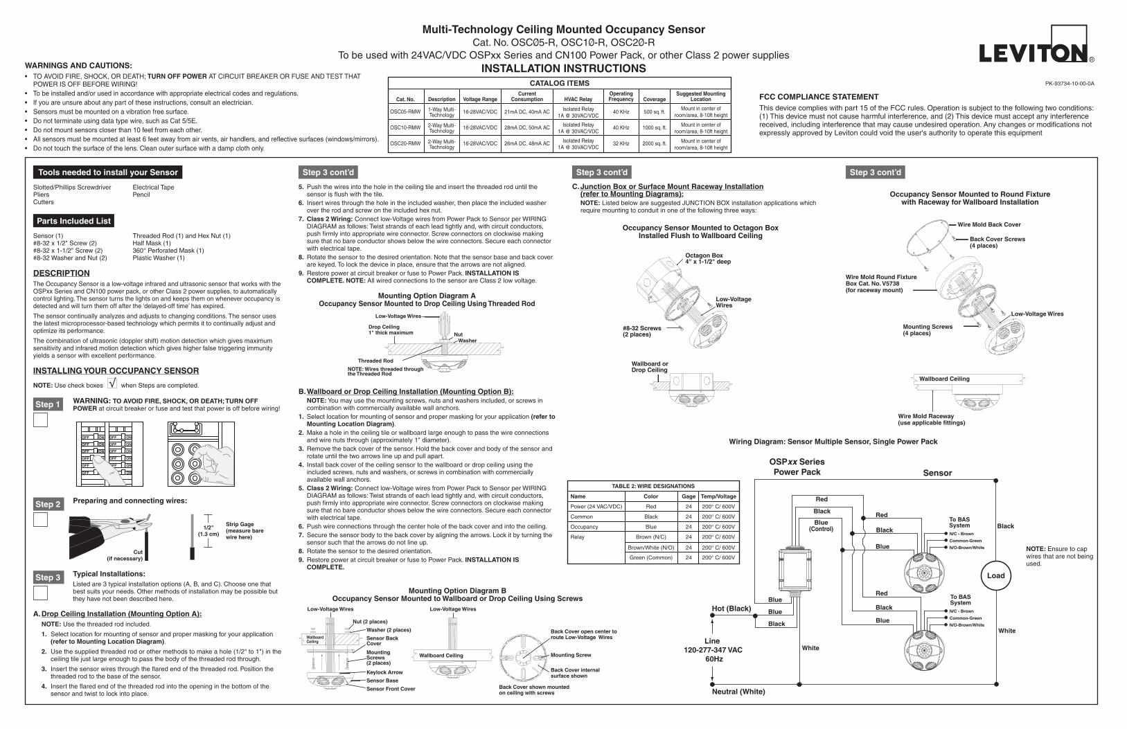
Hot (Black)
Neutral (White)
Load
Blue(Control)
Black
Red
Red
Blue
White
Black
White
Black
Red
Blue
Blue
BlueBlack
Black
Line 120-277-347 VAC
60Hz
SensorOSPxx SeriesPower Pack
To BASSystem
To BASSystem
N/C - Brown
N/O-Brown/White
Common-Green
N/C - Brown
N/O-Brown/White
Common-Green
Occupancy Sensor Mounted to Octagon BoxInstalled Flush to Wallboard Ceiling
Occupancy Sensor Mounted to Round Fixturewith Raceway for Wallboard Installation
Wiring Diagram: Sensor Multiple Sensor, Single Power Pack
NOTE: Ensure to cap wires that are not being used.
Mounting Option Diagram AOccupancy Sensor Mounted to Drop Ceiling Using Threaded Rod
Mounting Option Diagram BOccupancy Sensor Mounted to Wallboard or Drop Ceiling Using Screws
PK-93734-10-00-0A
Preparing and connecting wires:
Cut (if necessary)
1/2"(1.3 cm)
Strip Gage (measure bare wire here)
Step 2
Step 1
ONOFF
ONOFF
ONOFF
ONOFF
ONOFF
ONOFF
ONOFFONOFF
ONOFF
ONOFF
ONOFF
ONOFF
WARNING: TO AVOID FIRE, SHOCK, OR DEATH; TURN OFF POWER at circuit breaker or fuse and test that power is off before wiring!
Typical Installations:Listed are 3 typical installation options (A, B, and C). Choose one that best suits your needs. Other methods of installation may be possible but they have not been described here.
Step 3
A. Drop Ceiling Installation (Mounting Option A): NOTE: Use the threaded rod included.
1. Select location for mounting of sensor and proper masking for your application (refer to Mounting Location Diagram).
2. Use the supplied threaded rod or other methods to make a hole (1/2" to 1") in the ceiling tile just large enough to pass the body of the threaded rod through.
3. Insert the sensor wires through the flared end of the threaded rod. Position the threaded rod to the base of the sensor.
4. Insert the flared end of the threaded rod into the opening in the bottom of the sensor and twist to lock into place.
TABLE 2: WIRE DESIGNATIONS
Name
Power (24 VAC/VDC)
Common
Occupancy
Relay
Color
Red
Black
Blue
Brown (N/C)
Brown/White (N/O)
Green (Common)
Gage
24
24
24
24
24
24
Temp/Voltage
200° C/ 600V
200° C/ 600V
200° C/ 600V
200° C/ 600V
200° C/ 600V
200° C/ 600V
WARNINGS AND CAUTIONS:• TO AVOID FIRE, SHOCK, OR DEATH; TURN OFF POWER AT CIRCUIT BREAKER OR FUSE AND TEST THAT
POWER IS OFF BEFORE WIRING!• To be installed and/or used in accordance with appropriate electrical codes and regulations.• If you are unsure about any part of these instructions, consult an electrician.• Sensors must be mounted on a vibration free surface.• Do not terminate using data type wire, such as Cat 5/5E.• Do not mount sensors closer than 10 feet from each other.• All sensors must be mounted at least 6 feet away from air vents, air handlers, and reflective surfaces (windows/mirrors).• Do not touch the surface of the lens. Clean outer surface with a damp cloth only.
Mount in center of room/area, 8-10ft height
Mount in center of room/area, 8-10ft height
Mount in center of room/area, 8-10ft height
Suggested Mounting Location
500 sq. ft.
1000 sq. ft.
2000 sq. ft.
Coverage
40 KHz
40 KHz
32 KHz
OperatingFrequency
Isolated Relay 1A @ 30VAC/VDC
Isolated Relay 1A @ 30VAC/VDC
Isolated Relay 1A @ 30VAC/VDC
HVAC Relay
OSC05-RMW
OSC10-RMW
OSC20-RMW
Cat. No.
1-Way Multi-Technology
2-Way Multi-Technology
2-Way Multi-Technology
Description
16-28VAC/VDC
16-28VAC/VDC
16-28VAC/VDC
Voltage Range
21mA DC, 40mA AC
28mA DC, 50mA AC
26mA DC, 48mA AC
Current Consumption
CATALOG ITEMS

LIMITED 5 YEAR WARRANTY AND EXCLUSIONSLeviton warrants to the original consumer purchaser and not for the benefit of anyone else that this product at the time of its sale by Leviton is free of defects in materials and workmanship under normal and proper use for five years from the purchase date. Leviton’s only obligation is to correct such defects by repair or replacement, at its option, if within such five year period the product is returned prepaid, with proof of purchase date, and a description of the problem to Leviton Manufacturing Co., Inc., Att: Quality Assurance Department, 201 North Service Road, Melville, New York 11747. This warranty excludes and there is disclaimed liability for labor for removal of this product or reinstallation. This warranty is void if this product is installed improperly or in an improper environment, overloaded, misused, opened, abused, or altered in any manner, or is not used under normal operating conditions or not in accordance with any labels or instructions. There are no other or implied warranties of any kind, including merchantability and fitness for a particular purpose, but if any implied warranty is required by the applicable jurisdiction, the duration of any such implied warranty, including merchantability and fitness for a particular purpose, is limited to five years. Leviton is not liable for incidental, indirect, special, or consequential damages, including without limitation, damage to, or loss of use of, any equipment, lost sales or profits or delay or failure to perform this warranty obligation. The remedies provided herein are the exclusive remedies under this warranty, whether based on contract, tort or otherwise.
Test Mode: To set the delayed-off time to 4 seconds for performing a walk test. While the sensor is in test mode, the LED’s will flash amber once every 6-7 seconds.1. ENSURE POWER IS ON.2. Remove front cover.3. Locate Dip Switch 3 in Bank B (B3) (refer to Figure 1). B3 will be in the OFF position from
the factory.4. To enter Test Mode, move switch to ON and back to OFF. The test mode has now been
entered with a 4 second time-out. NOTE: If B3 is already in the ON position, then test mode can be entered by just moving it to the OFF position.
NOTES:1. The timer will remain in the 4 second test mode for 15 minutes, then automatically exit test
mode and reset to the delayed-off time setting as defined by the black timer knob.2. To manually take the timer out of the 4 second test mode, simply toggle the switch B3 from
OFF to ON and back to OFF.Isolated Relay Operation:The Isolated Relay supports HVAC and other Class 2 low voltage signal lines up to 1A at 30VAC/VDC. It is a single-pole, double throw relay with Normally Open (N/O), Normally Closed (N/C), and Common wires. It follows occupancy such that the N/O wire is connected to common during occupancy.Mounting Height:Recommended mounting height for standard lens (default lens on unit) is 8 feet. Recommended mounting height for the mid-range lens (supplementary lens) is 8-20 feet. Note: Ultrasonic sensitivity may be reduced with mounting heights above 8 feet.
OPERATION
• Multi-Tech Mode: This is the default mode of operation for the sensor. PIR technology turns lights on in this mode; however, motion detection by either technology will keep the lights on. If neither technology detects motion, the lights turn off after the delayed-off time.
• Single-Tech Mode: Only one technology is active in this mode. The technology is selected by the dip switches. Motion detection by the selected technology - PIR or ultrasonic - will turn on the lights as well as keep them on. When motion is not detected, the lights will turn off after the delayed-off time.
• Delayed-Off time: The sensor is designed to turn the lights off if no motion is detected after a specified time. This length of time is called the delayed-off time and is set using the timer (Black) knob on the sensor. The adapting patterns will modify the delayed-off time to fit the parameters of each installation based on environmental conditions and occupancy patterns.
• Walk-through Mode: The walk-through feature is useful when a room is momentarily occupied. With this feature, the sensor will turn the lights off shortly after the person leaves the room. The walk-through feature works as follows: When a person enters the room, the lights will turn on. If the person leaves the room before the default walk-through timeout of 2.5 minutes, the sensor will turn the lights off. If the person stays in the room for longer than 2.5 minutes, the sensor will proceed to the standard operation.
• LED Operation: There are two LED indicators that will flash when motion is detected. The LED flash can be disabled using the LED disable switch setting. Green flash indicates motion detection by ultrasonic technology. Red flash indicates motion detection by infrared technology.
ADAPTIVE FUNCTIONS
The Sensor continually analyzes the parameters of the motion detection signal and adjusts its internal operation to maximize detection of motion while minimizing the effects of noise (electrical noise, air currents, temperature changes, etc…).Operation:When the lights turn on, the sensor initially enters the “walk-through” mode. Once the room is occupied for longer than 2.5 minutes, the sensor exits the “walk-through” mode and enters the “Occupied” mode. When the sensor is first installed, the delayed-off time for the occupied mode is based on the Time adjustment settings. While the sensor is in use, the delayed-off time will change, based on how the sensor adapts to the room conditions. Whenever the sensor subsequently turns on, the value of the delayed-off time will be the adapted value (refer to Occupancy Pattern Learning For Delayed Off Time).The adapted settings can be reset using the DIP switch.Occupancy Pattern Learning For Delayed Off Time:The sensor will automatically change the delayed off time in response to the occupancy and environmental conditions of the space it is installed in. The sensor analyzes the motion signal properties and will minimize the delayed off time duration when there is frequent motion detection, and lengthen the delayed off time duration when there is weak and infrequent motion detection.In the case of a false-off condition (lights turn off when the room is occupied), the delayed off time duration will immediately be lengthened to prevent further false turn offs.Occupancy Pattern Learning for Ultrasonic Technology:The sensor learns the occupancy patterns of a space during the course of a day, for a seven day period. At any given time, the sensor will look at the collected data and adjust its ultrasonic sensitivity. The sensor will adjust the sensitivity to make it less likely to turn on during a period of non-occupancy and more likely to turn on during a period of occupancy. This adapting feature is not applicable when the sensor is in PIR only mode.
SETTINGS
Default Settings:Adjustment knob settings as per “recommended manual settings,” (refer to Table 3 and Figure 1).All switches in the OFF position, except A4 is set to ON (refer to Table 4).
TABLE 3 : ADJUSTMENT KNOB SETTINGSKnobColor
Red
Black
Green
Function
Sets the infraredrange
Sets the ultrasonicrange
Delayed - Off Time
Knob Setting
Range SettingFull CCW = min. (OFF)Full CW = max.
Range SettingFull CCW = min. (OFF)Full CW = max.
Full CCW = min. (30 sec)Full CW = max. (30 min.)
SymbolFactory Default
Setting
75 %
50 %(10 min)
50 %
• For technical assistance, contact us at 1-800-824-3005• Visit our website at www.leviton.com
Figure 1 Minimum and Default Settings
MIN. MAX.
Adjust Knob Rotation Direction
30 sec
5 min
30 min
20 min
10 min
Delayed Off Time Selection (Black Knob)
0
20
11.5
11.5
8.5
8.5
20 TOP VIEW
SIDE VIEW
0 20 23 17
11 15 5.6 9 3
8
0
Minor Motion, Ultrasonic
Major Motion, Ultrasonic
Major Motion, IR
Figure 2 (Cat. No. OSC05) Field-of-View Ranges
0
20
11.5
11.5
8.5
8.5
20
SIDE VIEW
TOP VIEW
23 23 17 17
8
0
11 11 15 15 20 20 9 9 3 3 0 5.6 5.6
Minor Motion, Ultrasonic
Major Motion, Ultrasonic
Major Motion, IR
Figure 3 (Cat. No. OSC10) Field-of-View Ranges
0
20
8
16
16
11.5
11.5
20
0 3 3 5.5 5.5 9 9 11 11 15 15 20 20 32 32 22.5 22.5
TOP VIEW
SIDE VIEW
Minor Motion, Ultrasonic
Major Motion, Ultrasonic
Major Motion, IR
Figure 4 (Cat. No.. OSC20) Field-of-View Ranges
TROUBLESHOOTING
• Lights do not turn ON - Circuit breaker or fuse has tripped. - Low-voltage miswired. To Test: Connect RED to BLUE wire at power pack to force
lights ON. - Line voltage miswired. To Test: Connect BLUE to BLUE relay wires (of power pack)
to force the lights ON.• Lights stay ON - Constant motion. To Test: Reduce RED and/or GREEN knob by 15%; remove
motion source. If unsatisfactory, move sensor. - Infrared sensor can "see" into hallway. To Test: Put sensor in timer test mode walk
and walk hallway. If lights continue to come ON, move sensor.• Light turns ON too long - Timer setting too high. To Test: Check switch settings. Typical setting is 10 minutes.
PRODUCT INFORMATION
PK-93734-10-00-0A© 2011 Leviton Mfg. Co., Inc.
By masking two sections,you can block hallway traffic.
Masking is not required in a cornermounting application. The sensor
cannot see hallway traffic.
MaskMounting Location Diagram
A B
ON ON
1 1A B
ON ON
1 1
Minimum Setting Factory Default Setting
DIP Switches
B3
*NOTE: This setting is only used if the Single Technology Option (Switch A1) is selected.
SWITCH
A1
A2*
A3
A4
B1
B2
B3
B4
TABLE 4: SWITCH SETTINGSSWITCH SETTINGS
Bank A
Bank B
SWITCH FUNCTIONS
Single/Multi-Tech Mode
PIR/Ultrasonic Mode
Manual Mode
Walk-Through Disable
Override to ON
Override to OFF
Test Mode
LEDs Disable
ON
ON
Single Tech
Ultrasonic
Auto Adapting Disabled
Walk-Through Disabled
Lights Forced ON
Lights Forced OFF
LEDs Diasabled
OFF
OFF
Multi-Tech
PIR
Auto Adapting Enabled
Walk-Through Enabled
Auto Mode
Auto Mode
LEDs Enabled
OFF ON OFF = Enter/Exit Test Mode
Figure 5 - (Mid-Range Lens) Field-of-View RangesNote: This lens is included with all PIR models
15
15
10
10
20
10
5
0 5 10 15 20 2530 25 20 15 10 5 30
5
5
0
TOP VIEW
SIDE VIEW