Multi Protocol Label Switching: Quality of Service ...
137
Rochester Institute of Technology Rochester Institute of Technology RIT Scholar Works RIT Scholar Works Theses 11-2006 Multi Protocol Label Switching: Quality of Service, Traffic Multi Protocol Label Switching: Quality of Service, Traffic Engineering application, and Virtual Private Network application Engineering application, and Virtual Private Network application Akshay Joshi Follow this and additional works at: https://scholarworks.rit.edu/theses Recommended Citation Recommended Citation Joshi, Akshay, "Multi Protocol Label Switching: Quality of Service, Traffic Engineering application, and Virtual Private Network application" (2006). Thesis. Rochester Institute of Technology. Accessed from This Thesis is brought to you for free and open access by RIT Scholar Works. It has been accepted for inclusion in Theses by an authorized administrator of RIT Scholar Works. For more information, please contact [email protected].
Transcript of Multi Protocol Label Switching: Quality of Service ...
Rochester Institute of Technology Rochester Institute of Technology
RIT Scholar Works RIT Scholar Works
Theses
11-2006
Multi Protocol Label Switching: Quality of Service, Traffic Multi Protocol Label Switching: Quality of Service, Traffic
Engineering application, and Virtual Private Network application Engineering application, and Virtual Private Network application
Akshay Joshi
Follow this and additional works at: https://scholarworks.rit.edu/theses
Recommended Citation Recommended Citation Joshi, Akshay, "Multi Protocol Label Switching: Quality of Service, Traffic Engineering application, and Virtual Private Network application" (2006). Thesis. Rochester Institute of Technology. Accessed from
This Thesis is brought to you for free and open access by RIT Scholar Works. It has been accepted for inclusion in Theses by an authorized administrator of RIT Scholar Works. For more information, please contact [email protected].
Multi Protocol Label Switching:
Quality of Service, Traffic Engineering
application, and Virtual Private
Network application.
November 2006
Thesis
By
Akshay Joshi
Graduate Student
Dept: Information Technology
Rochester Institute of Technology

Rochester Institute of Technology
B. Thomas Golisano College of
Computing and Information Sciences
Master of Science in Information Technology
Thesis Approval Form
Student Name: Akshay Joshi
Thesis Title: Multiprotocol Label Switching: Quality of Service, Traffic Engineering, and Virtual Private Networks
Name
Prof. S Ivia Perez-Hard Chair
Prof. Luther Troell Committee Member
Dr. Ashok Jain Committee Member
Thesis Committee
Signature Date
Sylvia Perez-Hardy
Luther Troell
Ashok M. Jain
Thesis Reproduction Permission Form
Rochester Institute of Technology
B. Thomas Golisano College of
Computing and Information Sciences
Master of Science in Information Technology
Multiprotocol Label Switching: Quality of Service, Traffic Engineering, and Virtual Private Networks
I, Akshay Joshi, hereby grant permission to the Wallace Library of the Rochester Institute of Technology to reproduce my thesis in whole or in part. Any reproduction must not be for commercial use or profit.
Date: 12/12/06 Signature of Author: _A_k_s_h_a-=.y_J_o_s_h_i __

Graduate Project
November 2006 MPLS: QoS and MPLs Applications
Hypothesis
Hypothesis
This thesis discusses the QoS feature, Traffic Engineering (TE) application, and Virtual Private
Network (VPN) application of the Multi Protocol Label Switching (MPLS) protocol. This thesis
concentrates on comparing MPLS with other prominent technologies such as Internet Protocol (IP),
Asynchronous Transfer Mode (ATM), and Frame Relay (FR). MPLS combines the flexibility of Internet
Protocol (IP) with the connection oriented approach of Asynchronous Transfer Mode (ATM) or Frame
Relay (FR). Section 1 lists several advantages MPLS brings over other technologies. Section 2 covers
architecture and a brief description of the key components of MPLS. The information provided in
Section 2 builds a background to compareMPLS with the other technologies in the rest ofthe sections.
Since it is anticipated that MPLS will be a main core network technology, MPLS is required to
work with two currently available QoS architectures: Integrated Service (IntServ) architecture and
Differentiated Service (DiffServ) architecture. Even though the MPLS does not introduce a new QoS
architecture or enhance the existing QoS architectures, it works seamlessly with both QoS architectures
and provides proper QoS support to the customer. Section 3 provides the details of how MPLS supports
various functions ofthe IntServ and DiffServ architectures.
TE helps Internet Service Provider (ISP) optimize the use of available resources, minimize the
operational costs, and maximize the revenues. MPLS provides efficient TE functions which prove to be
superior to IP and ATM/FR. Section 4 discusses how MPLS supports the TE functionality and what
makes MPLS superior than other competitive technologies.
ATM and FR are still required as a backbone technology in some areas where converting the
backbone to IP or MPLS does not make sense or customer demands simply require ATM or FR. In this
case, like IP, it is important for MPLS to work with ATM and FR. Section 5 highlights the
interoperability issues and solutions forMPLS while working in conjunction with ATM and FR.

Graduate Project
MPLS: QoS and MPLS ApplicationsNovember 2006
Hypothesis
In section 6, various VPN tunnel types are discussed and compared with the MPLS VPN tunnel
type. The MPLS VPN tunnel type is concluded as an optimum tunnel approach because it provides
security, multiplexing, and the other important features that are required by the VPN customer and the
ISP. Various MPLS layer 2 and layer 3 VPN solutions are also briefly discussed. In section 7 I conclude
with the details of an actual implementation of a layer 3 MPLS VPN solution that works in conjunction
with Border Gateway Protocol (BGP).

Graduate Project
November 2006 MPLS: QoS and MPLS Applications
Table of Contents
Table ofContents
1 Introduction 1-1
1.1 High-Level MPLS Benefits 1-1
2 MPLS Concepts and Architecture 2-1
2.1 MPLS: Layer 2.5 Protocol 2-1
2.2 Various Terminologies 2-1
2.3 Concepts and Architecture ofMPLS 2-3
2.3.1 Forwarding Component 2-3
2.3.1.1 Label 2-3
2.3.1.2 Functional Equivalence Class (FEC) 2-4
2.3.1.3 Label Switching ForwardingMechanism 2-5
2.3.2 Control Component 2-6
2.3.2.1 Label Bindings 2-6
2.3.3 Label Distribution Protocol 2-6
2.3.3.1 LDP Header Format 2-6
2.3.3.2 LDP Message Format 2-6
2.3.3.3 Type-Length-Value Encoding Scheme 2-6
2.3.3.4 Discovery of other LSRs 2-6
3 Quality of Service in MPLS 3-6
3.1 QoS Fundamental Blocks 3-6
3.2 QoS Architectures andMPLS 3-6
3.2.1 Integrated Services andMPLS 3-6
3.2.1.1 Resource Reservation Protocol (RSVP) 3-6
3.2.1.2 MPLS Related Enhancements 3-6
3.2.2 Differentiated Services andMPLS 3-6
3.2.2.1 Differentiated Service Code Point (DSCP) 3-6
3.2.2.2 Per Hope Behavior (PHB) 3-6
3.2.2.3 MPLS Related Enhancements 3-6
4 Introduction: MPLS Traffic Engineering 4-6
4.1 Important Steps forMPLS Traffic Engineering 4-6
4.1.1 Compute a Path 4-6
4.1.2 Setup Forwarding State forMPLS Traffic Engineering 4-6
4.1.2.1 RSVP-TE 4-6
4.1.2.2 CR-LDP 4-6
4.1.2.3 Comparison ofCR-LDP and RSVP-TE 4-6
4.2 Various Traffic Engineering Solutions 4-6
4.2.1 Traffic Engineering Solution based on ATM OverlayModel 4-6
4.2.2 Traffic Engineering Solution based on IP Routing 4-6
4.2.3 Traffic Engineering Solution based on MPLS 4-6
4.2.3.1 Traffic Trunks 4-6
5 Introduction: ATM and Frame Relay 5-6
5.1 Main Forwarding Components for ATM and FR 5-6
5.1.1 Forwarding Unit 5-6
5.1.2 Virtual Circuit Hierarchies 5-6
5.1.3 Permanent Virtual Circuits (PVCs) and Switched Virtual Circuits (SVCs) 5-6
5.2 MPLS Label Encoding in ATM and FR 5-6
5.2.1 Solution to TTL Processing 5-6
5.3 Example: MPLS over FR 5-6

Graduate Project
MPLS: QoS and MPLS ApplicationsNovember 2006
Table of Contents
6 Introduction: MPLS Virtual Private Network 6-6
6.1 VPNModels 6-6
6.1.1 Overlay VPNModel 6-6
6.1.2 Peer VPNModel 6-6
6.2 VPN Tunnel 6-6
6.3 VPN Solutions 6-6
6.3.1 Layer 2 MPLS VPN Solution 6-6
6.3.2 Layer 3 MPLS VPN Solution 6-6
7 MPLS/BGP VPN Implementation 7-6
8 References/Bibliography 8-6

Graduate Project
November 2006 MPLS: QoS and MPLS Applications
List of Figures
List of Figures
Figure 1-1. Fish Problem in the Network 1-3
Figure 2-1. Label SwitchingNetwork 2-2
Figure 2-2. Label Operations 2-6
Figure 2-3. Shim Label Header 2-6
Figure 2-4. Label Switching ForwardingMechanism 2-6
Figure 2-5. Label Switching ForwardingMechanism: Label Stacking 2-6
Figure 2-6. LDP Header Format 2-6
Figure 2-7. LDP Message Format 2-6
Figure 2-8. Type-Length-Value (TLV) Encoding Format 2-6
Figure 3-1. Policing and Shaping Effect on Traffic 3-6
Figure 3-2. WFQ: Flow with IndependentWeight 3-6
Figure 3-3. WFQ: Multiple Flows with SameWeight 3-6
Figure 3^1. Basic RSVP Flow in Host and Router 3-6
Figure 3-5. RSVP PATHMessage Flow and RSVP RESV Message Flow 3-6
Figure 3-6. Label BindingMechanism in RSVP 3-6
Figure 3-7. IP Packet 3-6
Figure 3-8 IP ToS Byte 3-6
Figure 3-9. IP ToS Byte for DSCP 3-6
Figure 3-10. E-LSP CarryingMultiple PHBs 3-6
Figure 3-11. L-LSPs Carrying Different PHBs 3-6
Figure 4-1. LSP Setup using RSVP-TE 4-6
Figure 4-2. LSP Setup using CR-LDP 4-6
Figure 4-3. ATM OverlayModel - Physical and Logical Layout 4-6
Figure 4-4. Layer 2 TE Solution Example 4-6
Figure 4-5. Layer 3 TE Solution Example 1 4-6
Figure 4-6. Layer 3 TE Solution Example 2 4-6
Figure 4-7. Layer 3 TE Solution Example 3 4-6
Figure 4-8. Traffic TrunkMapping to LSPs 4-6
Figure 5-1. ATM Cell Header 5-6
Figure 5-2. Frame Relay Frame Header 5-6
Figure 5-3. ATM Virtual Circuit Hierarchy 5-6
Figure 5-4. FR Virtual Circuit Hierarchy 5-6
Figure 5-5. IP/MPLS Packet overMPLS/FRNetwork 5-6
Figure 6-1. VPN Mesh Topology 6-6
Figure 6-2. VPN Hub-Spoke Topology 6-6
Figure 6-3. VPN PartialMesh Topology 6-6
Figure 6-4. VPN OverlayModel 6-6
Figure 6-5. VPN PeerModel 6-6
Figure 6-6. GRE Header 6-6
Figure 6-7. Data Packet with IP-IP Tunneling 6-6
Figure 6-8. IPSec Transport Mode and Tunnel Mode 6-6
Figure 6-9. L2TPv3 Header 6-6
Figure 6-10. Virtual Private Network Solutions at Layer 2 and Layer 3 6-6
Figure 6-11. MPLS Packet in Layer 2 MPLS VPN Solution 6-6
Figure 7-1. Layer 3 MPLS/BGP VPN Configuration 7-6

Graduate Project
MPLS: QoS and MPLS ApplicationsNovember 2006
This page is intentionally left blank.

Graduate Project
November 2006 MPLS: QoS and MPLS Applications
List of Tables
List ofTables
Table 2-1. Comparison ofFEC Coarse Granularity and Fine Granularity 2-4
Table 3-1. Standard PHBs and Associated QoS Treatment 3-6
Table 3-2. Mapping of IP Precedence, DSCP Class, andMPLS Exp field 3-6
Table 4- 1 . Routing Protocol and Associated DefaultAdministrative Distance 4-6
Table 5-1. MPLS Label EncodingMethod for ATM 5-6
Table 5-1. Comparison ofVPN Tunnel Types in Respect to Various Features 6-6

Graduate Project
MPLS: QoS and MPLS ApplicationsNovember 2006
This page is intentionally left blank.

Graduate Project
November 2006 MPLS: QoS and MPLS Applications
Introduction
1 Introduction
In the current growingmarket, the need for an excellent and scalable infrastructure is very important.
Whether it's a call center, a car manufacturing unit, a pharmaceutical company, or data networks, every
industry in the present world is trying to compete with each other based on Quality of Service (QoS) and
performance. Ifwe talk about the Internet, which is the prime area of this research thesis, the number of
computers in the network is growing very fast. Along with an increased number of users, bandwidth
hungry applications are being developed to provide cheaper and more flexible services; e.g. Voice over
Internet Protocol (VoIP). With the increasing demand for complex services, thecustomers'
expectations
have accelerated for faster Internet service, scalable networks, simple upgrades, proper Quality of
Service, and robust Traffic Engineering. The traditional Internet Protocol (IP) network has become
popular because of the numerous advantages it provides such as easy and flexible architecture, global
connectivity, easy expandability, etc. However, with the increased number of complex applications and
the rapidly expanding Internet, IP is unable to properly handle delay-sensitive traffic such as Voice,
Video, and High-Speed data. As the number of users in the Internet grows, the Internet should be able to
accommodate them and provide consistent performance. The ability of the Internet to cope with the
growing number of users is called scalability. IP does not provide scalability and proper Traffic
Engineering. As a result, traffic loss, unexpected delay, poor performance, inefficient handling of delay
sensitive traffic occurs. This can be a big concern since Internet has become backbone of almost each
business.
Multiprotocol Label Switching (MPLS) overcomes most of the above mentioned issues IP is unable
to handle. The following section lists some of the high-level benefits MPLS provides over the
conventional IP.
1.1 High-LevelMPLS Benefits
1-1
Graduate Project
MPLS: QoS and MPLS Applications November 2006
Introduction
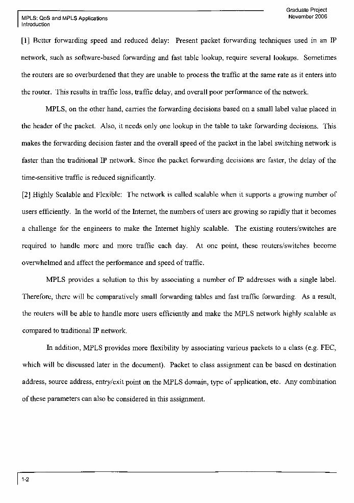
[1] Better forwarding speed and reduced delay: Present packet forwarding techniques used in an IP
network, such as software-based forwarding and fast table lookup, require several lookups. Sometimes
the routers are so overburdened that they are unable to process the traffic at the same rate as it enters into
the router. This results in traffic loss, traffic delay, and overall poor performance of the network.
MPLS, on the other hand, carries the forwarding decisions based on a small label value placed in
the header of the packet. Also, it needs only one lookup in the table to take forwarding decisions. This
makes the forwarding decision faster and the overall speed of the packet in the label switching network is
faster than the traditional IP network. Since the packet forwarding decisions are faster, the delay of the
time-sensitive traffic is reduced significantly.
[2] Highly Scalable and Flexible: The network is called scalable when it supports a growing number of
users efficiently. In the world ofthe Internet, the numbers ofusers are growing so rapidly that it becomes
a challenge for the engineers to make the Internet highly scalable. The existing routers/switches are
required to handle more and more traffic each day. At one point, these routers/switches become
overwhelmed and affect the performance and speed of traffic.
MPLS provides a solution to this by associating a number of IP addresses with a single label.
Therefore, there will be comparatively small forwarding tables and fast traffic forwarding. As a result,
the routers will be able to handle more users efficiently and make the MPLS network highly scalable as
compared to traditional IP network.
In addition, MPLS provides more flexibility by associating various packets to a class (e.g. FEC,
which will be discussed later in the document). Packet to class assignment can be based on destination
address, source address, entry/exit point on the MPLS domain, type of application, etc. Any combination
of these parameters can also be considered in this assignment.
1-2

Graduate Project
November 2006 MPLS: QoS and MPLS Applications
Introduction
[3] Less Variable Delay or Jitter: When a packet travels through the network, it is passed through many
nodes (i.e. routers or switches) before actually reaching to its destination. At each network node, the
header of packet is examined in order to make the proper forwarding decision. During this examination
process, there will be some delay observed at each node. Accumulation of such variable delay, while the
packet travels through Internet, is called Jitter. MPLS makes faster routing decisions so that the Jitter is
less as compared to traditional IP routing.
[4] Simple Forwarding Parameters: In MPLS, a packet is forwarded using a small label and not through
complex forwarding algorithms. There is a control mechanism that binds the label to the traffic. Such
bindings take place only once prior to the packet entering into the MPLS network. Once the packet is in
theMPLS network, the forwarding is completely based on its label.
[5] Better Control over the Forwarding Path: The IP protocol uses destination IP addresses as a primary
forwarding parameter. This method is also referred to as destination-routing. However, a very well
known situation can occur in the network that is completely out of the control of the network planners.
This situation is known as the "fish problem", as shown in Figure 1-1.
A \ / D
C
__
Figure 1-1. Fish Problem in the Network
The task - The main task is to forward a packet from routerA or from router B to router F.
1-3

Graduate Project
MPLS: QoS and MPLS ApplicationsNovember 2006
Introduction
Destination Based Routing- When the packet originating from A or B reaches C, the packet will
be forwarded to either D or E and then to F. The route of the packet from router C to router F is not pre
determined.
MPLS Based Routing- The packet originating from router A or router B has particular label
associated with it. Based on the label value, router C is told to forward the packet to either D or E and
then to F. Here, the route ofpacket from router C is predetermined and based on the label value it will go
to either D or E. Let's assume that the link between router C and D is OC3 (Optical Carrier signal level 3)
while the link between router C and E is OC12 (Optical Carrier signal level 12). In this situation, the
network planner will have better control over the forwarding path usingMPLS based routing as compared
to destination based routing.
1-4

Graduate Project
November 2006 MPLS: QoS and MPLS Applications
Quality of Service in MPLS
2 MPLS Concepts and Architecture
As discussed earlier, MPLS provides many benefits over conventional IP. However, before MPLS came
into existence, various equipment vendors made efforts to develop proprietary label switching
technologies. Some of them are Ipsilon's IP switching, IBM's Aggregate Route-based IP Switching
(ARIS), and Cisco's Tag Switching. Cisco's Tag Switching became very popular and it drove the Internet
Engineering Task Force (IETF) to create the MPLS standard committee. As a result, most ofthe concepts
and architecture designs in Tag Switching have been inherited by theMPLS architecture.
2.1 MPLS: Layer 2.5 Protocol
So far I have presented the advantages of MPLS without much of a discussion on what MPLS is in
technical terms. MPLS is neither a network layer (layer 3) protocol nor a data link layer (layer 2)
protocol. It actually resides between layer 2 and layer 3; therefore, sometimes it is referred to as layer 2.5
protocol. Network layer routing has two main functional components: forwarding components and
control components. Each router in the Internet contains both components to handle traffic properly.
Before we get into more details of each component, let's summarize the various terminologies used in
definingMPLS.
2.2 Various Terminologies
Here are some of the important terms that are commonly used in discussing a MPLS network. We will
use this terminology though out this document. The following Figure 2-1 represents a basic network
topology in the Internet.
2-1

MPLS: QoS and MPLS Applications
Quality of Service in MPLS
Graduate Project
November 2006
1
End User 1\(server/local router)
Label Switch Domain
Label Switch Path
End User 2
(server/local router)
Figure 2-1. Label Switching Network
Label Switch Domain: The label switch domain is defined by a network administrator and it contains
one or more physical networks. The routers contained in the label switch domain are forwarding traffic
usingMPLS technology.
Edge Router: The router that is placed on the boundary of the label switch domain is called an edge
router. The edge router connects a user or non-label switch domain to the label switch domain. The edge
router is responsible for pushing the label into the packet or pulling the label out of the packet. If the flow
of traffic is from End User 1 to End User 2, then edge router A is also called the Ingress (entry) router and
router D is also called the Egress (exit) router. An Ingress router pushes a label into the packet header
and an Egress router pulls a label from the packet header.
Label Switch Router (LSR): If a router is contained within the label switch domain then it is called as
LSR. One of the very important functions of the LSR is to swap the label and make the appropriate
forwarding decision.
2-2

Graduate Project
November 2006 MPLS: QoS and MPLS Applications
Quality of Service in MPLS
Label Switch Path (LSP): The traffic path used for the packets in the label switch domain is called the
Label Switch Path. The LSPs are dynamically created by the Label Distribution Protocol (LDP), which
will be discussed shortly, and IP routing.
2.3 Concepts and Architecture ofMPLS
MPLS came into existence after a successful design ofTag Switching by Cisco Systems. Tag Switching
contains two important Label Switching components: the forwarding component and control component.
As a result, MPLS can also be efficiently explained in the context of these two components.
2.3.1 Forwarding Component
The forwarding component is responsible for forwarding packets from the input interface to the output
interface across the router. It requires the following two things to make the forwarding decision:
(i) a forwarding table
(ii) the information carried in the packet header
The forwarding component also consists of a set of procedures that a router uses to make forwarding
decision on a packet. InMPLS, the following components are considered as forwarding components:
2.3.1.1 Label
As we have discussed before, MPLS is a label switching technology and it makes forwarding decisions
based on a label. A label is not like an IP address or any other packet header information, but a small,
fixed length entity. The label value changes as the packet travel through different nodes in the network.
We will see the data flow in next few sections.
2-3

MPLS: QoS and MPLS Applications
Quality of Service in MPLS
Graduate Project
November 2006
2.3.1.2 Functional Equivalence Class (FEC)
FEC is also referred to as Forwarding Equivalence Class. FEC is one of the main concepts of label
switching. The forwarding component consists of a set of procedures to make forwarding decisions. The
set of procedures depends on the type of packets. Since there are many types of packets to route in the
Internet, grouping some types of packets can be useful in making forwarding decisions simple and fast.
Such grouping of packets is called a FEC. A label is assigned to each FEC. Each FEC has a FEC value
which can be used to set the priority of the FEC. FECs are very useful in efficiently providing QoS
operations. For example, voice and video traffic can be given higher priorities than other types of traffic.
Also, the FEC provides excellent forwarding granularity from coarse forwarding granularities to fine
forwarding granularities. The type of granularity is achieved by considering a number of different
parameters such as source IP address, destination IP address, source port number, destination port
number, protocol ID, etc. The following table provides a comparison of FEC coarse granularity versus
FEC fine granularity.
Table 2-1. Comparison of FEC Coarse Granularity and Fine Granularity
FEC Coarse Granularity FEC Fine Granularity
If FEC is built using destination network
address, it provides coarse granularity
If FEC is built using port numbers, Protocol
ID, etc. then it provides fine granularity
More scalable Less scalable
Less flexible since it does not support classes
of traffic and some QoS operations
More flexible since it has more traffic
classification
Smaller forwarding tables Larger forwarding tables
The advantage of MPLS is that it allows both coarse and fine granularity to work together based on
customer's needs.
2-4

Graduate Project
November 2006 MPLS: QoS and MPLS Applications
Quality of Service in MPLS
2.3.1.3 Label Switching Forwarding Mechanism
Forwarding in a label switched environment is completely based on label swapping. When a packet
enters the Ingress router of the MPLS network, the label is pushed in the packet between the layer 2 and
layer 3 header. When the packet is traveling through the MPLS domain, the LSR swaps the label
according to the forwarding table. Such label swapping happens at all LSRs. At the Egress router, the
label is extracted from the IP packet before the packet is sent out to its destination. Two very important
components oftheMPLS forwarding mechanism are: the Forwarding Table and the Shim Label Header.
Forwarding Table or Label Switching Table:
The MPLS forwarding table is maintained by each router in the MPLS domain. Usually, there are two
types of forwarding tables:
(i) Generic forwarding table that contains information related to all router interfaces
(ii) Interface specific forwarding table
Each forwarding table contains various entries. Each entry contains the following information:
packet receiving port# (i.e. for incoming packet)
label on incoming packet
packet forwarding port# (i.e. for outgoing packet)
label on outgoing packet
next hop or next router information (i.e. IP address)
Instructions to perform on labels. There are three simple instructions introduced:
(i)"push"
to insert a label (usually at Ingress router)
(ii)"swap"
to change the label (usually at LSR)
(iii)"pop"
to extract a label (usually at Egress router)
2-5

MPLS: QoS and MPLS Applications
Quality of Service in MPLS
Graduate Project
November 2006
Sometimes the entry also contains the information related to what resources the packet should use. For
example, a particular forwarding packet queue can also be included into the forwarding entry. The
forwarding table may also contain more than one entry for any incoming label. For example, inMulticast
routing, if a packet is required to be forwarded to more than one outgoing interface the forwarding table
will contain a subentry for each outgoing interfaces.
The table at Ingress router will look similar to the following:
Port In Label In Port Out Label Out Instruction Next HopX ... A 27 push 39.27.5.6
Y B 13 push 129.28.9.4
The table at Egress router will look similar to the following:
Port In Label In Port Out Label Out Instruction Next HopA 34 P ...
pop 39.27.5.6
B 9 Q Pop 129.28.9.4
The table at LSRs will look similar to the following:
Port In Label In Port Out Label Out Instruction Next Hop
X 13 A 27 swap 39.27.5.6
Y 75 B 500 swap 129.28.9.4
The label should be pushed at the router from which a packet enters the MPLS network. The label is
swapped at the router inside MPLS network and the label is popped at the router from which a packet
exits theMPLS network.
2-6

Graduate Project
November 2006 MPLS: QoS and MPLS Applications
Quality of Service in MPLS
Label Switch Domain
Label Switch Path
End User 2
(server/focal router)
Figure 2-2. Label Operations
Shim LabelHeader
As soon as the packet enters into ingress router, a shim header is pushed between link layer header (layer
2) and network layer header (layer 3). The shim header is 32 bits long. Out of 32 bits, 20 bits are used
for the label, 8 bits for Time To Live, one bit for stack information, and three bits for experimental
functions.
PayloadLayer 4
Header
Layer 3
Header
SHIM
Label
Header
Layer 2
Header
to
6__c a>
TTL ra
53
E
X
LU
Label
8 bits >. .3
.1 Kll I 20 bits .
bits
Figure 2-3. Shim Label Header
Since the shim label header is independent of layer 2 and layer 3, it allows support for many link layer
technologies and network layer technologies.
2-7

MPLS: QoS and MPLS Applications
Quality of Service in MPLS
The ForwardingMechanism
The following Figure 2-4 indicates the forwarding mechanism in MPLS.
Graduate Project
November 2006
Label In Function Label Out
- Push 9
End User 1 \ ^(server/local router) s-~-_
>-
/ Edge Router
Label In Function Label Out
13 Swap 8
Label Switch Domain
Label Switch Path
Labelln Function Label Out
9 Swap 13
B2s B
_abelSwitch Router
m
End User 2
server/local router)
Figure 2-4. Label Switching ForwardingMechanism
The exchange of labels is usually performed by the Label Distribution Protocol (LDP), which will be
discussed later in the document. Let's assume that the routers in the above given network have exchanged
labels and know the LSP for each packet. Now, each router in the network contains the label switching
forwarding table. The following forwarding sequence will occur to a packet which originates from End
User 1 and is destined for End User 2 (see Figure 2-4).
Packet enters Router A via portAl
Router A pushes (or assigns) Label 9 to the packet
When the packet is received at Router B, Router B examines its forwarding table and looks for an
entry that is associated with Label 9. It is also possible that there is more than one entry (i.e.
subentry) for the incoming Label 9 if the packet is forMulticast routing. Router B finds the entry
and swaps Label 9 with Label 1 3 and forwards the packet to next hop router C via interface B2
2-8

Graduate Project
November 2006 MPLS: qoS and MPLs Applications
Quality of Service in MPLS
A similar process occurs at Router C and the Label 13 is swapped with Label 8. The packet is
now forwarded to Router D.
Router D examines the packet and its forwarding table. It determines that the Label 8 should be
popped (or removed) since the destination address for that packet is only one hop away.
Packet is forwarded to End User 2
One of the main properties of the forwarding mechanism used by MPLS is that each LSR receives the
information needed to forward the packet. This information contains what resources the packet should
use and where to forward the packet. Since all the information is received together, only one look up is
required to forward the packet. This feature of label switching demonstrates that it is a high performance
network technology.
Use of label stack: Sometimes a packet may travel through manyMPLS or label switching domains (it is
also referred to as an Autonomous System). In this situation, the LSP is determined using two steps:
(i) edge routers on each domain exchange the label information associated with other domains
(ii) LSRs within the domain exchange local labels. When multiple labels are stacked, the Last In
First Out (LIFO) mechanism is used.
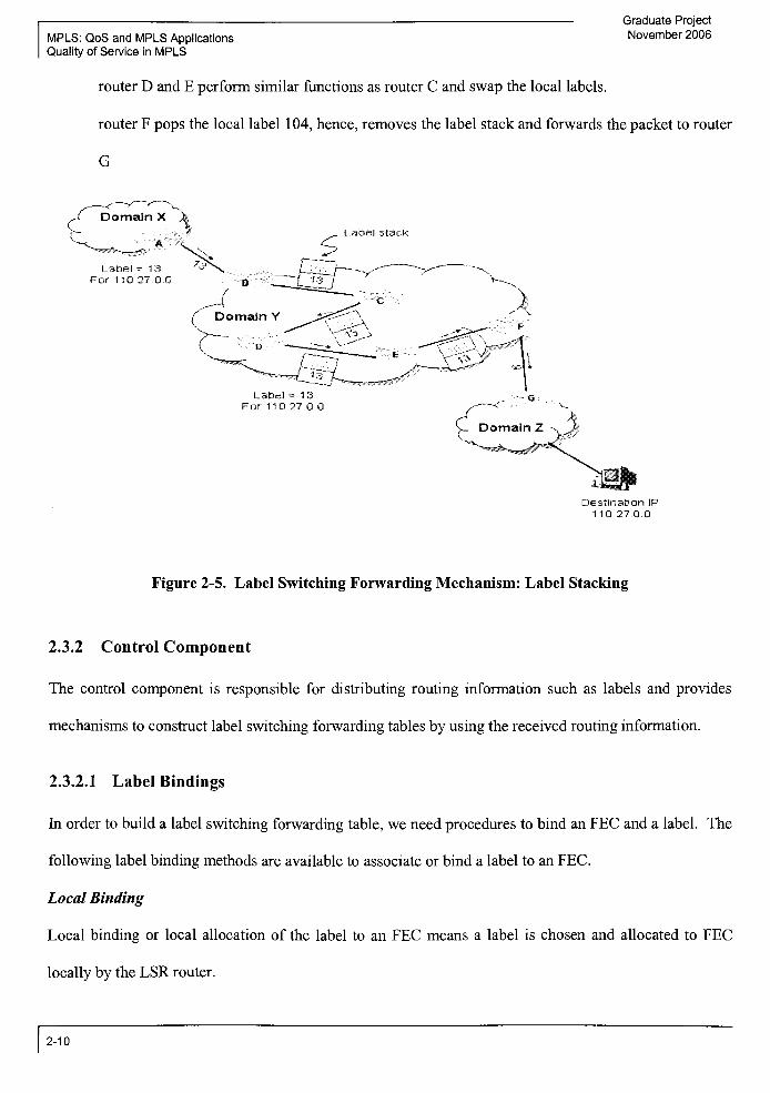
According to Figure 2-5 below, domain Y is using label 13 and domain Z is using label 9 to reach to
network 110.27.0.0. The label values 13 and 9 are called domain level labels and are not distributed to
any internal LSRs such as router C and D. Similarly, the label 101, 102, and 103 are called local labels
and are not distributed to routerA and F. As packet travels from A to F:
routerA sends packet with domain label 13
router B pushes the local label 101. In the label stack, the top label or the last inserted label is
101. Now the packet is carrying two labels: 13, and 101
router C never examines the label 1 3 which is at the bottom in the stack and swaps the local label
101 with 102. Now the packet is carrying two labels: 13, and 102
2-9
MPLS: QoS and MPLS Applications
Quality of Service in MPLS
Graduate Project
November 2006
router D and E perform similar functions as router C and swap the local labels.
router F pops the local label 104, hence, removes the label stack and forwards the packet to router
G
Label stack
Label = 1 3
For 110.27.0.0
Destination IP
110 27 0 0
Figure 2-5. Label Switching ForwardingMechanism: Label Stacking
2.3.2 Control Component
The control component is responsible for distributing routing information such as labels and provides
mechanisms to construct label switching forwarding tables by using the received routing information.
2.3.2.1 Label Bindings
In order to build a label switching forwarding table, we need procedures to bind an FEC and a label. The
following label bindingmethods are available to associate or bind a label to an FEC.
LocalBinding
Local binding or local allocation of the label to an FEC means a label is chosen and allocated to FEC
locally by the LSR router.
2-10

Graduate Project
November 2006 MPLS: QoS and MPLS Applications
Quality of Service in MPLS
Remote Binding
Remote bindingmeans an LSR has choosen label binding information received from a remote LSR.
Upstream Binding
Usually, if the flow ofpackets is from router A to router B then the router A is considered as an upstream
router (Ru) and router B is considered as a downstream router (Rd). When label allocation is done by an
upstream router then it is called an upstream binding. In such binding, the label from the local binding
(by Ru) is used as an outgoing label and the label from the remote binding (by Rd) is used as an incoming
label.
Downstream Binding
When the label allocation is done by a downstream router then it is called a downstream binding. In such
binding, the label from the remote binding (by Rd) is used as an outgoing label and the label from the
local binding (by Ru) is used as an incoming label.
ControlDriven Binding
The control driven binding is setup with the use of control messages which are usually supported by the
Label Distribution Protocol (LDP). Sometimes it is also setup bymanual provisioning.
Data Driven Binding
The data driven binding is setup after analyzing one ormore data packets.
2.3.3 Label Distribution Protocol
There are three ways to distribute labels among the LSRs.
i) Using the Label Distribution Protocol (LDP)
ii) Using the Resource Reservation Protocol (RSVP)
iii) Piggybacked on other routing protocols such as the Border Gateway Protocol (BGP)
and the Open Shortest Path First (OSPF). In this case BGP is used to distribute labels
between domains and OSPF is used to distribute local labels inside domain.
2-11

Graduate Project
MPLS: QoS and MPLS Applications November 2006
Quality of Service in MPLS
In this section, a brief description of the Label Distribution Protocol is provided. The Label Distribution
Protocol is a newly developed protocol inMPLS to provide a set of procedures and messages to advertise
and distribute labels among LSRs. In other words, the LDP assigns labels to the routes that have been
created by the routing protocol like the Interior Gateway Protocol (IGP). As we discussed earlier, this
labeled path is called a LSP. The LDP messages are exchanged between adjacent LSRs as well as non-
adjacent LSRs. The LSRs involved in the message exchange are called LDP peers. A LDP session must
be established between two LSRs before exchanging LDP messages. With only one exception, the LDP
provides a connection oriented mechanism to distribute labels. There are four categories of LDP
messages:
(I) DiscoveryMessages: used to discover and maintain the presence ofLSRs in a network
(II) Session Messages: used to establish, maintain, and terminate the session between LDP peers
(in) Advertisement Messages: used to create, change, and delete label mappings for FECs
(IV) Notification Messages: used to distribute advisory information and to signal error information
The Discovery Messages are User Datagram Protocol (UDP) based since, to discover other LSRs in a
network, a Hello Message will be sent over a UDP port of all LSRs in the same subnet. The Session,
Advertisement, and Notification messages are TCP based since the correct operation of LDP requires
reliable and connection oriented mechanism to delivermessages.
2.3.3.1 LDP Header Format
Each LDP message (also called as Protocol Data Unit (PDU)) begins with an LDP header. One or more
LDP messages may be combined together in a single datagram to reduce LDP header processing time. .
The fields in the LDP header are:
Version: LDP version number
PDU Length: Total length of the PDU excluding the version and PDU length field
2-12

Graduate Project
November 2006 MPLS: QoS and MPLS Applications
Quality of Service in MPLS
LDP ID: LDP Identifier uniquely identifies the label space of the sending LSR of this LDP
message or messages. The first four bytes indicate the IP address of LSR and the last two bytes
indicate the label space within the LSR.
The following Figure 2-6 shows the LDP header format
1 Byte
Version PDU Length
LDP Message
Figure 2-6. LDP Header Format
Label Spaces andLDP ID
Label spaces are a set ofpossible labels which are used in the label bindings. LDP supports two types of
label spaces: interface-specific and platform-wide.
Interface-specific : An interface-specific label space uses interface resources for labels. For example,
label-controlled ATM interfaces uses Virtual Channel Identifier (VCI) as the labels or Frame Relay
interfaces uses Data Link Connection Identifier (DLCI) as a label. Use of interface-specific labels is
more useful when the two directly connected LSRs are sending traffic over that interface.
Platform-wide: Platform-wide label spaces are used for the interfaces that can share the same labels. If
the Platform-wide label space is used then the two bytes of label space are set to zero.
When multiple label spaces are used for an LSR, the label identifier or LDP ID is used to uniquely
identify each label space. Use of multiple label spaces is very common in an ATM network where two
ATM switches are connected to each other using multiple ATM links or a mix ofmultiple types of links
such as Ethernet links and ATM links.
2-13

MPLS: QoS and MPLS Applications
Quality of Service in MPLS
2.3.3.2 LDPMessage Format
All LDP messages follow the format shown below in Figure 2-7.
Graduate Project
November 2006
bit1 Byte | 1 Byte 1 Byte 1 Byte
U Message Type Message Length
Message ID
Mandatory Parameters
Optional Parameters
Figure 2-7. LDP Message Format
U bit: Unknown message bit. IfU is set to 1 then the message is categorized as unknown and it
will be discarded by the receiver LSR.
Message Type: Type ofmessage.
Message Length: Total length ofMessage ID, Mandatory Parameters, and Optional Parameters.
Message ID: A unique identifier for this message being sent by the LSR. This identifier is used
to facilitate the identification of all packets that apply to this message.
Mandatory Parameters: Set of mandatory or required parameters that are of variable length.
Some messages may not require mandatory parameters.
Optional Parameters: Set of optional parameters that are of variable length. Some messages may
not require optional parameters.
Various LDPMessages Types
Notification Message: To notify the peer LSR about an error conditions such as keep alive timer
expiration, failure of an LSP session, etc.
Hello Message: To discover other LSR in the network.
InitializationMessage: To initialize the session between LDP peers.
2-14

Graduate Project
November 2006 MPLS: QoS and MPLS Applications
Quality of Service in MPLS
KeepAlive Message: To continuously check the integrity ofthe TCP connection that supports the
LDP session.
Address Message: To advertise interface addresses to other LSRs.
Address Withdraw Message: To withdraw the previously advertised interface addresses (by
means ofAddress Message).
Label MappingMessage: To advertise the FEC-label mapping or binding.
Label Request Message: To request FEC-label binding information from other LSR.
Label Abort Request Message: To abort an outstanding Label Request Message.
Label WithdrawMessage: To destroy bindings between FECs and labels.
Label Release Message: To inform other LSRs that there is no need for any specific FEC-label
bindings.
2.3.3.3 Type-Length-Value Fncoding Scheme
All LDP messages are encoded using the TLV scheme as shown in Figure 2-8.
Mbit1Byte 1 Byte 1 Byte 1 Byte
u F Type Length
Value
Figure 2-8. Type-Length-Value (TLV) Encoding Format
U bit: Unknown bit. If U bit is set to 0 then the entire message is ignored and returned to the
originator. IfU bit is set to 1 then the message is processed.
F bit: Forward bit. If F is set to 0 then the message is not forwarded. If F is set to 1 then the
message is forwarded. (Note: In order for the message within the TLV to be forwarded, the U bit
and F bit must be set to 1.)
2-15

Graduate Project
MPLS: QoS and MPLS Applications November 2006
Quality of Service in MPLS
Type: Type ofTLV
Length: Length ofthe TLV
Value: Parameters of the TLV. The Value may contain one or more TLV encoded messages. It
is like a TLV inside a TLV.
2.3.3.4 Discovery of other LSRs
The LSRs discover each other in two ways: basic discovery method and extended discovery method.
Basic Discovery Method: This method is used by an LSR to discover other LSRs that are directly
connected by a link. A LSR sends a Link Hello or Hello Message as a UDP packet to all routers on the
subnet. The Hello Message usually carries the LDP ID for the label space that the LSR intends to use.
ExtendedDiscoveryMethod: This method is used by an LSR to discover other LSRs that are not directly
connected to it. The LSR sends a Targeted Hello Message to a specific IP address. The Targeted Hello
Message usually carries the LDP ID for the label space that the LSR intends to use and some optional
parameters.
2-16

Graduate Project
November 2006 MPLS: QoS and MPLS Applications
Quality of Service in MPLS
3 Quality of Service in MPLS
Quality of Service is not a new term. It is used in almost all business segments. In general, if a customer
pays more for any service then in return he/she seeks exceptional service. The Internet is growing from
all latitudes and longitudes. It carries diverse and delay sensitive traffic. Therefore, it is required to
classify them and make sure that the traffic with delay sensitiveness is treated with higher priority than
the traffic with less delay sensitiveness. In simple words, the handling of traffic in various priorities and
flawless performance is called Quality of Service (QoS). Before QoS was implemented in the Internet, all
traffic was treated on Best-Effort basis. This means that network will do best to route traffic to its
destination. But, in Best-Effort phenomena, if congestion occurs then packets are more susceptible to
loss. This approach is not workable since voice and video traffic certainly need assurance of proper
delivery. MPLS does not provide new QoS architectures but supports the existing QoS architectures that
IP is supporting. However, MPLS is a useful technology for QoS because it provides better resource
allocation, smaller table sizes, easier management, and support existing IP QoS architecture more
effectively, hi the Internet world, there are mainly four measurement units for QoS:
(i) Available Bandwidth
(ii) Latency
(iii) Jitter or Variable Delay
(iv) Packet Loss
(i) Available Bandwidth: It is important to make sure that the bandwidth requirements are met for those
applications which need it. If the network contains low bandwidth and voice traffic is transported over it
then users will definitely experience broken sentences. Similarly, when the video traffic is transported
over the low bandwidth network then the picture will start sticking and the enjoyment of the video is
adversely affected. So, bandwidth is an important factor.
3-1

Graduate Project
MPLS: QoS and MPLS ApplicationsNovember 2006
Quality of Service in MPLS
However, it is also important to understand that provisioning more bandwidth is not the only solution.
For example, ifmore bandwidth is provisioned in the network can solve the problem for the time being.
What if a link failure occurs in the network and all traffic of that link is routed on the link with higher
bandwidth or over-provisioned bandwidth? In such a case, the over-provisioned bandwidth on a
particular network link or segment will become under-provisioned due to the extra traffic routed from
other links. Also, if bandwidth is over-provisioned on a link that is used mostly for data traffic and
suddenly a voice or video traffic is placed on this link then what will happen? The voice and video traffic
have higher bandwidth requirements; as a result, the network link with over-provisioned bandwidth will
become under-provisioned due to placement of voice and video traffic. Therefore, proper network
planning and other factors are need to be considered while attempt to achieve end-to-end QoS.
(ii) Latency: Latency is a time that a packet takes in traveling from a sender node to a receiver node.
Sometimes, it is also considered a time a packet takes to make a round trip from the source to the
destination and back to the source. Various parameters, such as propagation time, transmission media,
and processing time at each network node, affects the delay. The voice and video data are very sensitive
to latency. Little more delay in transporting voice and video data has negative impact on Quality of
Service to the application.
(iii) Jitter (Variable Delay): Jitter is a delay between two packets at receiving end. When there is a
heavy load in the network, the data must be buffered and queued in any given network node. As a result,
the amount of delay between two packets is inconsistent (variable). This variable delay is called Jitter.
The voice traffic is very sensitive to Jitter because, inconsistent delay will cause breaking voice.
(iv) Packet Loss: In data network, packets may get lost or dropped due to so several reasons. One
common reason is higher network utilization or congestion. In this case, the drop in voice or video
packets creates unrecognizable sentences to the listener. Therefore, it is very critical to maintain lower
packet loss.
3-2

Graduate Project
November 2006 MPLS: QoS and MPLS Applications
Quality of Service in MPLS
3.1 QoS Fundamental Blocks
The QoS is provided with two types of granularity across network; Coarse and Fine. Each type of
granularities is provided along with a separate QoS Architectures or QoS Models. The fine granularity
means the QoS is provided on per-flow or per-application basis. This architecture is called QoS
Integrated Service (Int-Serv) Architecture. The coarse granularity means QoS is provided on a group of
flow or aggregated traffic. This architecture is called QoS Differentiated Service (Diff-Serv)
Architecture.
To achieve end-to-end QoS, both architectures require each packet to pass through certain processes.
These processes, as listed below, are known as QoS fundamental blocks.
(i) Classifying/Marking
(ii) Policing/Shaping
(iii) Queuing/Scheduling
(iv) Congestion Avoidance
(I) Classifying/Marking: The packets are classified based on level ofQoS is required. Classification is
done based on source IP address, destination IP address, source port number, destination port number,
and/or protocol ID. The classification is done at the edge router before applying any QoS parameters.
Once the traffic is classified, it is marked so that the other core devices can easily associate class of
service and then apply policy. The packet is marked at various OSI layer to ensure proper QoS handling
from sender to receiver.
Layer 2 - packet marking with 802.1Q/p
Layer 3 - packetmarking with Diffserv Code Point (DSCP)
Layer 2.5 - packet marking withMPLS Exp bits
Despite ofthe classification andmarking, the packet does not get end-to-end QoS without policing it.
3-3

MPLS: QoS and MPLS Applications
Quality of Service in MPLS
Graduate Project
November 2006
(ID Policing/Shaping: According to web definitions, policing is "the process of discarding packets (by a
dropper) within a traffic stream in accordance with the state of a corresponding meter enforcing a traffic
profile"1. In other words, traffic policing drops traffic if it exceeds given data rate (defined by data
meter). Traffic shaping is similar to policing except that the shaping keeps excess packets in a queue and
then transmits them over the period of time. Below are few charts (Figure 3-1) showing major difference
between policing and shaping. Shaping smoothes the traffic burst.
Time Time
Time
Traffic Rate__________________
Time
Figure 3-1. Policing and Shaping Effect onTraffic2
The following table indicates major differences between policing and shaping
Policing Shaping
Drops excess packets above the given data rate Buffers and queues excess packets and process
them over the period of time.
Applies at the incoming interface as well as
outgoing interface
Applies at the outgoing interface only.
136-
1http://qos.ittc.ku.edu/study/glossary.html
2http://www.nanoq.orq/mtq-0602/pdf/sathiamurthi.pdf
3-4

Graduate Project
November 2006 MPLS: QoS and MPLS Applications
Quality of Service in MPLS
Delays due to queuing traffic is not supported Delay due to queuing traffic is supported
Both, policing and shaping, use token bucket as a traffic meter. The token bucket usually works in the
following way:
(a) Tokens are put into bucket at a given data rate.
(b) Each token contains length ofthe packet (in bits) that it allows the node to send.
(c) The traffic meter checks the packet size and then pulls out the number of tokens required to send that
packet.
(d) If the bucket does not contain enough tokens to send a packet, according to traffic policing, the packet
is dropped. However, in the same situation, the traffic shaping mechanism stores the excess packets into
buffer and wait for enough tokens to send out the packets.
(e) In the case when the token bucket is full of tokens than more tokens are discarded.
(Ill) Queuing/Scheduling: Queuing is a method to de-queue packets from a certain queue based on
required service levels. Several queuing mechanisms are available. Few of them are listed below.
(a) First In First Out (FIFO): The packet arriving first is always processed first. When the capacity of
queue is achieved, the excess incoming packets are dropped.
(b) Priority Queuing: In the priority queuing, each packet is assigned a priority based on level of service
requested. All the packets marked with higher priority go in the different queue then the packets marked
as lower priority. There could be many priority queues. All of the packets in the higher priority queue
are attended first. The packets in the lower priority queue are processed only when there are no packets in
the higher priority queue. Therefore, one big flaw of this method is that the traffic with lower priority
gets little or no attention. In traditional IP network, the priority is derived from the IP Type of Service
(TOS) precedence field. There are 3 bits reserved for IP TOS field. Therefore, 8 priorities can be derived
from 3 bits. Similarly, in MPLS, the priorities are derived from EXP field in the shim header. EXP field
is 3 bits long, thus, 8 priorities are available in the MPLS network.
3-5

Graduate Project
MPLS: QoS and MPLS Applications November 2006
Quality of Service in MPLS
(c) Fair Queuing: In fair queuing method, each packet is assigned a type or flow. There are several
queues possible based on types or flows. The packet with particular type assignment is placed on the
queue with that type. The processing of packet is done as one packet per queue. In other words, one
packet in each queue is processed one by one then the second packet on each queue is processed and so
on. This is better than priority queuing because processing of each queue is done simultaneously rather
than in sequence. Each type of flow ofpackets receives equal allocation of available bandwidth, thus, this
method is called fair queuing.
(d) Weighted Fair Queuing (WFQ): In this method, weight is applied to each type of flow of traffic.
Weight is a measure to indicate the bandwidth requirement of the flow. Higher weight is assigned to the
flow of traffic which required higher bandwidth. If total weight is X and the weight of a single flow is Y
then an available bandwidth for this single flow is Y/X.
^r Packet Stream
D ? ? rT
Flow A with weight =1~~
^
? ? ? a ^ ^r>^L
Flow B with weight= 2 LER
a a a
Flow C with weight= 3
Figure 3-2. WFQ: Flow with Independent Weight
As per the above Figure 3-2, the flow C has higher weight than flow B and flow B has a higher weight
than flow A.
Total Weight X = 1 +2 +3 + 6
Available bandwidth for a flow with weight Y = Y/X
Available bandwidth to precedence 1 (or flow with weight=
1)= 1/6
Available bandwidth to precedence 2 (or flow with weight= 2)
= 2/6
3-6

Graduate Project
November 2006 MPLS: QoS and MPLS Applications
Quality of Service in MPLS
Available bandwidth to precedence 3 (or flow withweight=
3)= 3/6
The bandwidth assigned to flow C is higher than B and B is higher than A.
As we discussed before, only 8 priorities are possible in MPLS. This is not enough because in MPLS,
there are many FEC classes; hence, many flows (assuming one flow per FEC class) are available. In
WFQ, many flows can also be assigned a single weight and the bandwidth can be allotted based on that.
? ? ??*" _s
Packet Stream
Flow A with weight= 1
? ? ? Q.-?
Flow B with weight= 2
^
^ER
? ? ?
Flow C with weight= 2
? ? ?
Flow D with weight= 3
Figure 3-3. WFQ: Multiple Flows with SameWeight
Total weight = 1 +2(2) + 3 = 8
Available bandwidth for precedence 1 = 1/8
Available bandwidth for precedence 2 = 2/8
Available bandwidth for precedence 3 = 3/8
(TV) Congestion Avoidance:
The network is considered to be congested when the capacity of the network to handle packets has been
reached and new packets are being dropped by the network. The most well known congestion control
method is defined for TCP, where the packet loss is considered as a prime factor to assume that the
network is congested. When the TCP sender realizes that the packets have been lost, it slows down the
transmission of packets and gradually increases the transmission of packet to ensure that no packets have
been lost. In order to make sure that the packets are not lost and to actively monitor the congestion, few
3-7

Graduate Project
MPLS: QoS and MPLS Applications November 2006
Quality of Service in MPLS
queue management techniques have been introduced. Traditionally, when the queue is reached to its
limit and the buffer is full, the tail drop occurs and all the additional packets are dropped. Due to packet
drops, the TCP hosts in the network will reduce the transmission rate and try to synchronize with each
other. All TCP hosts slow down the transmission rate until the congestion is completely cleared. Once
the congestion is cleared, all TCP hosts start increasing transmission rate. As a result, the transmission
rate is going up and down which leaves the transmission links under utilized during some periods. There
are other queue management techniques that reduce number of packets dropped in routers and provide
lower delay in the interactive services such as voice and video conferencing. We will be discussing two
important queue management techniques here: (i) Random Early Detection and (ii) Weighted Random
Early Detection.
(a) Random Early Detection (RED)
RED works with the TCP transport protocol.
The main goal ofRED is to
- reduce number ofpackets dropped at router
- avoid global synchronizations ofTCP hosts
- provide congestion avoidance by means of early dropping packets and controlling average queue size
RED introduces minimum threshold (MinTh) and maximum threshold (MaxTh) values for the queue size.
All traffic below MinTh is transmitted without observing any drop packets. All traffic above MaxTh is
dropped. The probability of traffic between MinTh and MaxTh being dropped is based on number of
packet increase. RED randomly drops the packets without considering the QoS parameters ofthe packet
to protect the queue from being fully utilized. As a result, it is not useful for the traffic with hard QoS
requirements.
(b) Weighted Random Early Detect (WRED):
WRED discards packets based on its QoS requirements and importance. WRED considers the MPLS
EXP bits to prioritize the packets. The packet with bits 000 in EXP bits (or IP precedence bits) is
3-8

Graduate Project
November 2006 MPLS: QoS and MPLS Applications
Quality of Service in MPLS
considered as lower priority traffic and is more likely to be discarded. The packet with bits 111 is
considered as higher priority traffic and is less likely to be discarded. The bits in the voice and video
packets can be set to 1 1 1 in order to minimize the probability ofbeing dropped.
3.2 QoS Architectures andMPLS
As mentioned earlier, MPLS neither introduces new QoS architecture nor enhances the existing IP QoS
architecture. However, MPLS does support the existing IP QoS architecture efficiently. There are two
QoS architecture defined for IP networks: Integrated Service (IntServ) and Differentiated Service
(DiffServ). In this section, we will highlight important parameters ofboth architectures and then examine
howMPLS supports these two architectures.
3.2.1 Integrated Services andMPLS
Integrated Services or IntServ architecture was developed by IETF in 1990s to satisfy guaranteedend-to-
end QoS for the applications that needs it. IntServ provides QoS guarantee to individual application or
flow; hence, it is also known as 'fine grained QoS approach'. IntServ introduced service classes based on
which the QoS requests can be made. In order to make QoS request, IntServ supports several signaling
protocols; to name a few such as Resource Reservation Protocol (RSVP), Simple Network Management
Protocol (SNMP). However, RSVP has been used as a main signaling protocol to make QoS requests.
Also, MPLS has been enhanced to support RSVP for its QoS needs and traffic engineering needs.
Therefore, we will also be briefly discussing RSVP in this section.
The IntServ architecture has introduced two main aspects to achieve QoS needs for an individual
application: (1) Service Classes and (2) Use ofRSVP to signal QoS requests using these service classes.
In IntServ, each application is expected to provide what type of traffic will be sending over the network
(i.e. Traffic Specifications-75pec) and what are the QoS needs of that traffic (i.e. Resource Specifications-
RSpec). IntServ expects all of the network nodes to perform all QoS fundamental functions (marking,
policing, queuing, scheduling, etc.).
3-9
Graduate Project
MPLS: QoS and MPLS Applications November 2006
Quality of Service in MPLS
Service Classes:
The following two service classes were introduced:
(i) Guaranteed Service: It is useful for the applications that require strict guarantee of bandwidth and
maximum delay. The application must provide the TSpec and RSpec information in order to receive
guarantee of bandwidth and to meet maximum delay requirement. The TSpec parameters are: maximum
packet size, a burst size, and the traffic rate of the token bucket or traffic meter. The RSpec parameter is
the required bandwidth or service rate for that application. In Guaranteed Service, there will be separate
queue for each flow. As a result, once the bandwidth is reserved for that flow (or service) and during a
day if that service is not required then the bandwidth is still assigned to the service; thus, low utilization
ofbandwidth is a drawback ofGuaranteed Service class.
(ii) Controlled Load: Controlled Load overcomes the drawback of Guaranteed Service by avoiding the
strict requirements on bandwidth and delay. However, the Controlled Load class makes sure that enough
resources are available to satisfy QoS needs of the application and at the same time other flows or
services also receive proper QoS treatment without compromising the performance.
3.2.1.1 Resource Reservation Protocol (RSVP)
The RSVP is a network control protocol and is developed by separate IETF group. It is not developed as
part of IntServ architecture or associated with the IntServ architecture at all. RSVP is a signaling protocol
that allows applications to request or to make reservation of QoS requirements in the network. The
network, in response, provides YES or NO answer to the application. RSVP also supports both unicast
and multicast traffic. RSVP has been enhanced to support MPLS QoS and MPLS Traffic Engineering.
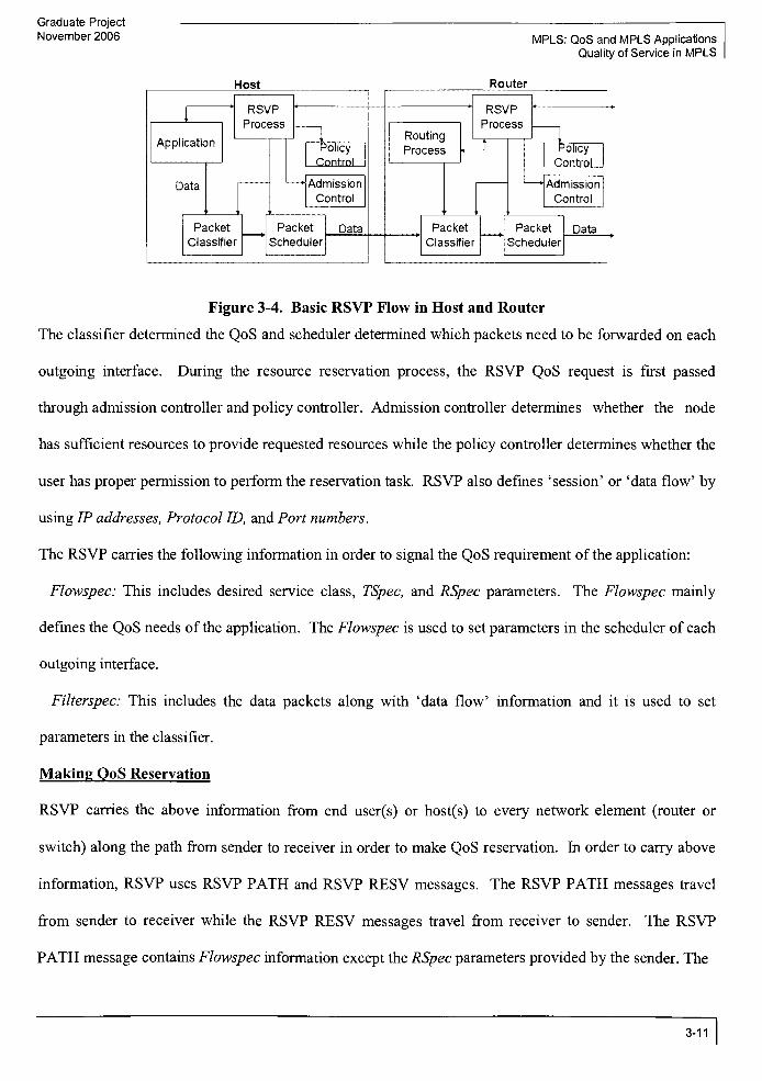
Therefore, it is important to discuss some aspects of RSVP protocol. The following Figure 3-4 shows
basic flow diagram ofRSVP.
3-10
Graduate Project
November 2006 MPLS: QoS and MPLS Applications
Quality of Service in MPLS
Host Router
RSVP
Process
RSVP
Process!
ApplicationRoutingProcess
1Policy Policy
Data Admission
Control
Admission
Control
a-
,
Packet
Classifier
Packet
Scheduler
Data Packet
Classifier
Packet
Scheduler
Data
Figure 3-4. Basic RSVP Flow in Host and Router
The classifier determined the QoS and scheduler determined which packets need to be forwarded on each
outgoing interface. During the resource reservation process, the RSVP QoS request is first passed
through admission controller and policy controller. Admission controller determines whether the node
has sufficient resources to provide requested resources while the policy controller determines whether the
user has proper permission to perform the reservation task. RSVP also defines'session'
or 'dataflow'
by
using IP addresses, Protocol ID, and Port numbers.
The RSVP carries the following information in order to signal the QoS requirement ofthe application:
Flowspec: This includes desired service class, TSpec, and RSpec parameters. The Flowspec mainly
defines the QoS needs ofthe application. The Flowspec is used to set parameters in the scheduler of each
outgoing interface.
Filterspec: This includes the data packets along with 'dataflow'
information and it is used to set
parameters in the classifier.
Making QoS Reservation
RSVP carries the above information from end user(s) or host(s) to every network element (router or
switch) along the path from sender to receiver in order to make QoS reservation. In order to carry above
information, RSVP uses RSVP PATH and RSVP RESV messages. The RSVP PATH messages travel
from sender to receiver while the RSVP RESV messages travel from receiver to sender. The RSVP
PATH message contains Flowspec information except the RSpec parameters provided by the sender. The
3-11

MPLS: QoS and MPLS Applications
Quality of Service in MPLS
Graduate Project
November 2006
RSVP PATH message is sent to a session or 'dataflow'
addresses which may be consisting of single
receiver (unicast address) or multiple receivers (multicast). When a receiver receives RSVP PATH
message, it responds with RSVP RESV message which identifies the session or 'dataflow'
for which the
QoS reservation is being made. The RSVP RESV message also contains RSpec parameters which
indicate what level of QoS is expected by the receiver. Both RSVP PATH and RSVP RESV messages
are being analyzed at each network element (router or switch) along the path from sender to receiver so
that resource allocation can take place at every necessary node along the transmission path. When a
message is passing through each network element, the network element performs all necessary checks as
depicted in the basic flow diagram of RSVP. Also, the reservation is always made unidirectional.
Therefore, for two way communication needs, two separate reservation needs to be made. Once the
resource reservation is made, each network element can identify which packet belongs to which
reservation by examining the source IP address, source port number, destination IP address, destination
port number, and the protocol ID. The following Figure 3-5 shows RSVP PATH message and RSVP
RESV message flow.
Host
A
J
RSVP PATH Message Flow
RSVP RESV Message Row Host
B 1'i
Figure 3-5. RSVP PATHMessage Flow and RSVP RESVMessage Flow
3-12

Graduate Project
November 2006 MPLS: QoS and MPLS Applications
Quality of Service in MPLS
RSVP is a 'softstate'
protocol, which means that in order to keep reservation active, RSVP PATH and
RSVP RESV messages must be exchanged periodically. Failure to do so will result in time-out of
reservation and eventually the reservation has been terminated.
3.2.1.2 MPLS Related Enhancements
All ofthe above discussed factors are applicable to MPLS except few things that won't work with MPLS
without enhancements. The enhancements to RSVP has been made to support MPLS for unicast address
only. As we know, MPLS supported network routes traffic based on labels and not IP addresses while to
setup the reservation, an IP address is a must to identify session number of 'data flow'. In order to route
the traffic in MPLS network, binding between data flows (that has reservations) and the labels must be
created and distributed to all LSRs along the path. Each data flow can be considered as an FEC in the
MPLS.
In order to distribute the label information in the RSVP messages, an RSVP LABEL object has been
created and carried inside the RSVP RESV message. When an LSR wants to send an RSVP RESV
messages to other LSR, it grabs a label from the free labels pool, generates an entry into the label
forwarding table as an incoming label, and sends out this label in the LABEL object ofthe RSVP RESV
message. When the receiver LSR receives this RSVP RESV message, it creates an entry into the label
forwarding table and put the label it received as an outgoing label. The receiver LSR also grabs a label
from its free labels pool and creates an entry into the label forwarding table which indicates that this new
label as an incoming label. The receiver LSR also places this new label into the LABLE object of this
RSVP RESV message before sending it to the other LSR along the path. This way the reservation has
been made from receiver to the sender LSR. If we recall the label binding types, the label binding
performed by the LSRs is done by using downstream label binding method. Also, once the LSP is
established, when a packet enters the edge LSR or LER, the LER examines the header information of the
packet and performs requested QoS operations on this packet for this reserved flow or data flow. Once all
QoS operations (policing/shaping, queuing/scheduling, etc.) are performed, the packet has been labeled
3-13

MPLS: QoS and MPLS Applications
Quality of Service in MPLS
Graduate Project
November 2006
according to the information provided in the label forwarding table. When this packet reaches to the LSR
(i.e. an intermediate LSR), the IP header or transport header ofthe packet is not examined, but, only the
label is examined and the LSR will find all QoS related parameters for that packet. Now, all the QoS
operations will be performed and the packet will be forwarded to the next LSR along the LSP. The label
binding information is being carried by either LDP or piggybacking on the existing routing protocol.
Host
A
R1
*Label27/
'm.
-__
R3"
LabeM3 /R4
RSVP PATH Message Flow
RSVP RESVMessage Flow Host
B .1
Figure 3-6. Label BindingMechanism in RSVP
According to Figure 3-6, Router Rl sends the RSVP PATH message to R2, R3, and eventually to R4.
Now, the following steps take place:
- R4 responds with the RSVP RESV message with the label 13, which is entered as an incoming label for
R4 in the forwarding table.
R3 receives the RSVP RESV message and assigns a new label 9 to the packet. The entry created in the
forwarding table ofR3 will have label 9 as an incoming label and label 13 as an outgoing label.
R2 receives the RSVP RESV message and assigns a new label 27 to the packet. The entry created in the
forwarding table ofR2 will have label 27 as an incoming label and label 9 as an outgoing label.
Rl receives the RSVP RESV message. The entry created in the forwarding table ofRl will have label
27 as an outgoing label.
3-14

Graduate Project
November 2006 MPLS: QoS and MPLS Applications
Quality of Service in MPLS
Important Points
The label binding information is being carried over by piggybacking on the existing routing protocol
rather than using LDP.
- At each LER and LSR, the IP header and transport header are not being examined. The packet is being
transported by using the label information given in the forwarding table.
At each LER and LSR, the QoS related parameters have been found by single table look up in the
forwarding table. According to QoS parameters, the packets are policed, scheduled, and queued.
Only the first LER (in above example, the Rl) needs to perform several functions to make sure which
packets belong to which reservation. All other LSRs along the LSP do not need to worry about this.
RSVP ScalabilityResolutionforMPLS
A very well known misunderstanding of RSVP is that it is not scalable because it supports only micro
flows (or a data flow that provides reservation for single application). In traditional IP world, the IP
header and transport header are examined at all nodes to make sure the packet belongs to particular
reservation. However, in MPLS, only the first LER along the LSP needs to worry about it. Various
options are allowed to configure Rl to accept wide range of packets. To allow various options of
selecting wide range of traffic, a new object called LABEL_REQUEST has been introduced in the RSVP
PATH message. The LABELJREQUEST will request a receiver LER to send the RSVP RESV message
to establish LSP and once the LSP is established, it allows specifying which higher level protocol will use
the LSP. This will allow aggregating more traffic to be transported over same LSP. For example, instead
of creating a micro flow, all traffic with same prefix or all traffic of same higher level protocol can be
assigned to the same LSP that provides required QoS needs. This is more useful in creating an LSP
between two sites of the companies to transport large amount of traffic with desired QoS needs.
Therefore, RSVP supports scalability by supporting aggregated traffic. The RSVP does not provide
scalable environment when it supports application specific flow.
3-15
Graduate Project
MPLS: QoS and MPLS Applications November 2006
Quality of Service in MPLS
Another issue has been discovered that the RSVP is soft state protocol thatmeans in order to maintain the
reservation, periodic refresh messages need to be exchanged. As a result, if a single router has to
maintain RSVP reservation details for large traffics then at some point it will become too much burden on
that router. Also, RSVP does not provide reliable service of message exchange. This means that if the
message is lost then the receiver RSVP node will rely on other refresh message rather than requesting
same message from the sender RSVP node. Therefore, in order to maintain reservation, a refresh
messages need to be sent out periodically with very short time intervals. This adds on to more traffic
overhead. In order to minimize the refresh traffic, the MPLS and RSVP IETF team provided a reliable
mechanism. New RSVP objects, theMESSAGEJD andMESSAGEJD_ACK have been introduced. If
Rl wants to send an RSVP PATH message indicating new state ofthe reservation to R2 then it assigns a
unique identifier and places it in the MESSAGE_ID object. Rl places thisMESSAGEID object into the
RSVP PATH message before sending the message to R2. R2 receives this message and acknowledges
the receipt of this message by sendingMESSAGE_ID_ACK object with the same identifier in the RSVP
message or a new ACK message. The Rl uses short intervals for the RSVP PATH messages that it sends
to R2 and other routers. Upon receipt of acknowledgement from R2 or other routers, Rl increases the
refresh timer. As a result, the refresh overhead is reduced by increasing refresh timer. If R2 receives
multiple RSVP messages with multiple identifiers to refresh state of the various reservations, it is allowed
to send more than one identifiers into single RSVP message back to Rl. This way the refresh traffic is
further reduced. This mechanism is called summary refresh. MPLS IETF group introduced a new
message called SREFRESH to carry more than one identifier back to sender LSR (i.e. Rl). The above
enhancements removed major scalability hurdles ofRSVP when using in MPLS environment.
3-16
Graduate Project
November 2006 MPLS: QoS and MPLS Applications
Quality of Service in MPLS
3.2.2 Differentiated Services and MPLS
Differentiated services or DiffServ architecture was developed by IETF in order to provide QoS to a class
of traffic rather than an individual application (i.e. IntServ approach). DiffServ architecture divides
traffic into small number of classes and allocates required resources to each class separately; hence,
DiffServ is also known as 'Coarse Grained QoSApproach"
For any network planner, the easiest way to
deploy DiffServ architecture is that to define the traffic into two simple classes: one class contains traffic
that does not need guaranteed QoS (Best Effort model) and the other class contains traffic with
guaranteed QoS service. The class can directly be marked into the packet using Differentiated Service
Code Point (DSCP).
3.2.2.1 Differentiated Service Code Point (DSCP)
The DSCP is carried into the 6 bit Differentiated Services field of the IP packet header. This field is part
ofthe Type of Service (ToS) byte ofthe IP packet header. Since there are 6 bits reserved for DSCP, up to
64 different classes can be defined. However, in practice only little number of classes can satisfy the
required QoS needs ofthe large network.
The following Figure 3-7 indicates the structure of IP packet.
0 34 7 8 15 16 23 24 31
Version LengthType of Serv
IP Pres/DSCPTotal Length
Identifier Flags Fragmented Offset
Time To Live Protocol Header Checksum
Source IP Address
Destination IP Address
Figure 3-7. IP Packet
The following Figure 3-8 indicates the IP Type of Service (ToS) byte.
3-17

MPLS: QoS and MPLS Applications
Quality of Service in MPLS
Graduate Project
November 2006
0 34 7 8 15 16 23 24 31
Version LengthType of Serv
IP Pres/DSCPTotal Length
..-Blt#1|2 | 3 4 5 6 7
"
""-8-...
IP Precedence D T R c
Figure 3-8 IP ToS Byte
The IP Precedence is made of 3 bits. D indicates Delay, T indicates Throughput, R indicates Reliability,
C indicates Cost, and last bit is reserved for other purpose. The value for D, T, R, and C can either be 0
(i.e. Normal) or 1 (i.e. High). As we know the first six bits of IP ToS field is mapped to DSCP field.
Therefore, last two bits (i.e. 7 and 8) are not considered for classification of traffic.
The following Figure 3-9 indicates the IP ToS byte when used for DSCP.
0 34 7 8 15 16 23 24 31
Version LengthType of Serv
IP Pres/DSCPTotal Length
..-"B'it#1|2 | 3 | 4 | 5 | 6
-
8 ...
Differentiated Service Code Point ECT CE
Figure 3-9. IP ToS Byte for DSCP
According to the Figure 3-9, the first six bits are used for DSCP. The ECT and CE bits are used for
Explicit Congestion Notification, which is not in the scope of this document. From these six bits, the first
three bits are mainly used to create classes of traffic and the other three bits are providing drop
preference.
3.2.2.2 Per Hope Behavior (PHB)
The DSCP identifies Per Hope Behavior (PHB) to define queuing and dropping mechanism at the each
router or LSR. The PHB can also be seen as a forwarding behavior applied to a set of packets that are
part ofDiffServ BehaviorAggregate (BA). Each LSR collects the packets from different source and
3-18
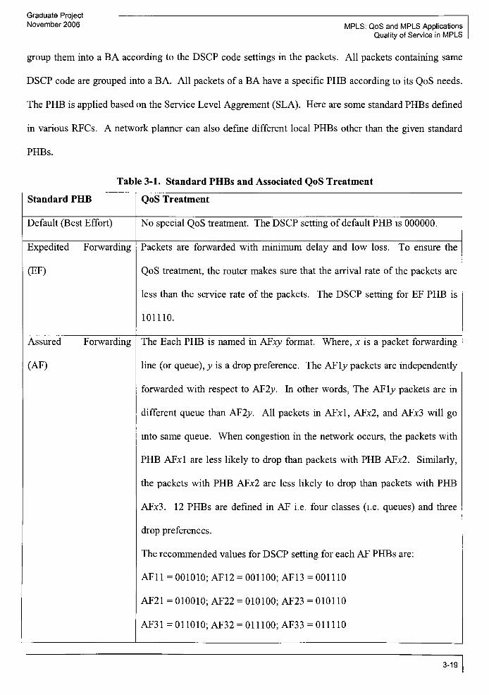
Graduate Project
November 2006 MPLS: QoS and MPLS Applications
Quality of Service in MPLS
group them into a BA according to the DSCP code settings in the packets. All packets containing same
DSCP code are grouped into a BA. All packets of a BA have a specific PHB according to its QoS needs.
The PHB is applied based on the Service Level Aggrement (SLA). Here are some standard PHBs defined
in various RFCs. A network planner can also define different local PHBs other than the given standard
PHBs.
Table 3-1. Standard PHBs and Associated QoS Treatment
Standard PHB QoS Treatment
Default (Best Effort) No special QoS treatment. The DSCP setting of default PHB is 000000.
Expedited Forwarding
(EF)
Packets are forwarded with minimum delay and low loss. To ensure the
QoS treatment, the router makes sure that the arrival rate of the packets are
less than the service rate of the packets. The DSCP setting for EF PHB is
101110.
Assured Forwarding
(AF)
The Each PHB is named in AFxy format. Where, x is a packet forwarding
line (or queue), v is a drop preference. The AFlv packets are independently
forwarded with respect to AF2v. In other words, The AFlv packets are in
different queue than AF2v. All packets in AFxl, AFx2, and AFx3 will go
into same queue. When congestion in the network occurs, the packets with
PHB AFcl are less likely to drop than packets with PHB AF;c2. Similarly,
the packets with PHB AF;c2 are less likely to drop than packets with PHB
AFx3. 12 PHBs are defined in AF i.e. four classes (i.e. queues) and three
drop preferences.
The recommended values for DSCP setting for each AF PHBs are:
AF1 1 = 001010; AF12 = 001 100; AF13= 001 110
AF21 =
010010; AF22 = 010100; AF23 = 0101 10
AF31=011010;AF32 = 011100;AF33 = 011110
3-19
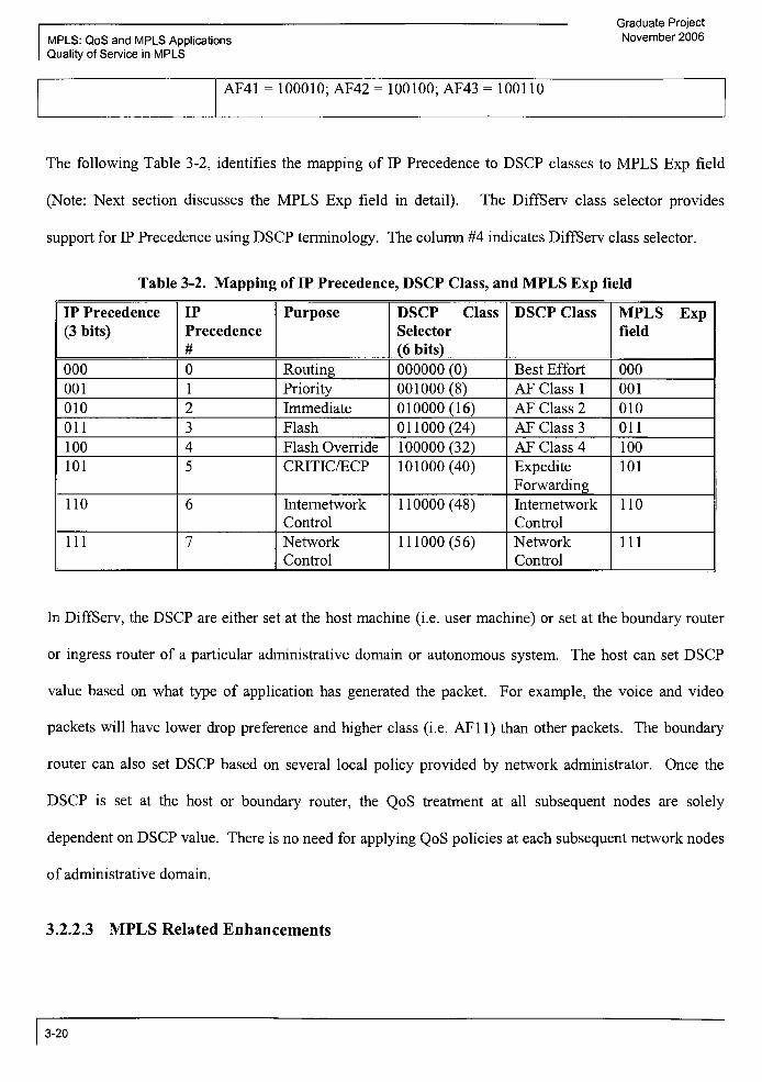
MPLS: QoS and MPLS Applications
Quality of Service in MPLS
Graduate Project
November 2006
AF41 = 100010; AF42 = 100100; AF43 = 100110
The following Table 3-2, identifies the mapping of IP Precedence to DSCP classes to MPLS Exp field
(Note: Next section discusses the MPLS Exp field in detail). The DiffServ class selector provides
support for IP Precedence using DSCP terminology. The column #4 indicates DiffServ class selector.
Table 3-2. Mapping of IP Precedence, DSCP Class, andMPLS Exp field
IP Precedence
(3 bits)
IP
Precedence
#
Purpose DSCP Class
Selector
(6 bits)
DSCP Class MPLS Expfield
000 0 Routing 000000 (0) Best Effort 000
001 1 Priority 001000 (8) AF Class 1 001
010 2 Immediate 010000(16) AF Class 2 010
011 3 Flash 011000(24) AF Class 3 011
100 4 Flash Override 100000 (32) AF Class 4 100
101 5 CRITIC/ECP 101000(40) Expedite
Forwarding
101
110 6 Internetwork
Control
110000(48) Internetwork
Control
110
111 7 Network
Control
111000(56) Network
Control
111
In DiffServ, the DSCP are either set at the host machine (i.e. user machine) or set at the boundary router
or ingress router of a particular administrative domain or autonomous system. The host can set DSCP
value based on what type of application has generated the packet. For example, the voice and video
packets will have lower drop preference and higher class (i.e. AF11) than other packets. The boundary
router can also set DSCP based on several local policy provided by network administrator. Once the
DSCP is set at the host or boundary router, the QoS treatment at all subsequent nodes are solely
dependent on DSCP value. There is no need for applying QoS policies at each subsequent network nodes
of administrative domain.
3.2.2.3 MPLS Related Enhancements
3-20

Graduate Project
November 2006 MPLS: QoS and MPLS Applications
Quality of Service in MPLS
There are several issues while using DiffServ model in the MPLS domain. The most important issue is
how to process the packet by applying proper QoS treatment and forward it to its destination. As we
know, DSCP is carried in the IP header and the MPLS routers do not check the IP header to perform
forwarding decision of the packet but it relies on the label information provided in shim header or link
layer header. Therefore, a mechanism is required to insert proper PHB information in the label header so
that each LSR can retrieve PHB information and process the packet with proper QoS treatment.
E-LSP (Exp-LSP): {PHB in shim header) The shim header contains experimental field (also known as
Exp field) which is 3-bit long. This field was designed to mark the packet for Differentiated Services.
The DSCP can be directly mapped into this Exp field, but, there is a length issue. The DSCP is 6-bit long
while the Exp field is 3-bit. The historical reasons behind this difference is that the MPLS shim header
was formalized in 1997 when the QoS classes (or Class of Service (CoS)) in the IP packet were derived
from 3 precedence bits provided in the IP ToS byte. The DiffServ design committee was originated in
1998 and started redefining the leading 6-bits ofthe IP ToS byte as DS field. Also, back in 1997 only the
Best-effort QoS model was famous and it was assumed that up to eight classes will be more than enough
to support most of the applications. With the 3 -bit Exp field, only eight PHBs are possible while the
DSCP can support up to 64 PHBs. Each LSR maintains a mapping of a Exp to PHBs it supports. All of
the LSRs need to be configured to map the Exp values to different PHBs. As long as up to 8 PHBs are
supported by the LSR, the Exp field is sufficient. Practically speaking, the eight QoS PHBs are more than
enough. Also, there is no signaling, such as RSVP, is required to reserve bandwidth. The label provides
information related to packet forwarding and the Exp field provides PHB information related to QoS
treatment that the packet seeks at each LSR. In order to setup the LSP, any label distribution mechanism
can be used. The LSP setup with the use of<label, Exp field> is called as E-LSP.
The following Figure 3-10 provides details ofE-LSP carrying two different PHBs.
3-21

MPLS: QoS and MPLS Applications
Quality of Service in MPLS
DSCP MPLS Exp
101110 101
001010 001
,E-LSP
Graduate Project
November 2006
D 1101110 001010Edge Router g=
i
MPLS Domain
Figure 3-10. E-LSP CarryingMultiple PHBs
As per the Figure 3-10, the edge router A (i.e. ingress router or ingress LSR) of the MPLS domain is
responsible for scanning all IP packets it receives, allocating a label to each packet, and setting the MPLS
Exp bits in the MPLS shim header so that the packet can be placed on to proper E-LSP. In our example,
the router Amaps two different PHBs ofDSCP to Exp field. The edge router A can be configured to map
the DSCP to Exp by using default values or through manual configuration. Also, router A assigns same
label to the packets that have same Exp bit value. As a result, in our example, packets with two separate
PHBs have same label assigned to it so that they can be placed on same E-LSP. But, remember that not
more than 8 PHBs can be placed on to E-LSP due to length restriction of the Exp field. Once the Exp
field is set at the edge router A, the Exp value must be consistent at all subsequent routers along theE-
LSP path. If the intermediate LSR needs to use different Exp value then it should be properly configured
and the Exp field needs to be remapped at that intermediate LSR. The Exp field identifies the queue
where packet needs to be placed on. In our example, the LSR B knows that the packet with Exp=101
needs to be put on EF queue and the packet with Exp=001 needs to be put on AF1 1 queue.
Important Benefits ofE-LSP:
(i) The operation of DiffServ over MPLS is simple and straight forward with the use of E-LSP. It is
similar to DiffServ over IP because MPLS uses 3 Exp bits while IP uses 3 IP precedence bits.
3-22

Graduate Project
November 2006 MPLS: QoS and MPLS Applications
Quality of Service in MPLS
(ii) No modification in the existing signaling and label distributionmechanisms are required.
(iii) Compare to IntServ architecture, the support formultiple PHBs over single E-LSP simplifies network
management by reducing number ofLSPs.
Main Limitations ofE-LSP:
(i) E-LSP can not support more than eight PHBs.
(ii) For ATM links, the shim header is not available because ATM cells contains CLP (Cell Loss Priority)
bit. Therefore, Exp to PHB mapping is not possible for ATM links.
(iii) E-LSPs with different PHBs can not be combined into one E-LSP.
L-LSP (Label-LSP): (PHB in Link Layer header or in Label itself) In case ifmore than eight PHBs are
needed in a particular network domain, the E-LSP will not work. Also, in the case ofATM links that do
not have shim header, the E-LSP will not work. In such cases, the label itself can be used to convey PHB
information. Therefore, the LSP setup with the use of label that carries PHB information is called as L-
LSP. As we know, the label can be bound to FEC. Similarly, the label must be bound to PHB as well.
Since the label is used to carry the PHB information, only single PHB can be carried over on each L-LSP.
PHB Scheduling Class (mainly to supportAFPHB class) :
The concept of carrying single PHB in each L-LSP does not work well with AF PHB class because each
AF PHB class has three drop preference (i.e. three DSCP values or three PHBs. For example, AF class x
has three PHBs AFxl, AFx2, AFx3). Also, it is prime requirement ofAF PHB class thatmember of same
class must not be reordered if they differ only in drop preference. Therefore, packets of the same AF
class but with different drop preferences must be forwarded on to same L-LSP. To meet this requirement,
a new term has been introduced which is called PHB Scheduling Class. PHB Scheduling Class is defined
as a group of PHBs that must not be reordered. Therefore, the three PHBs under each AF class must be
forwarded on to same L-LSP. There are four PHB Scheduling Classes available for AF PHB class.
1. AFly= AF1 1, AF12, and AF13 must be forwarded in same L-LSP
3-23

Graduate Project
MPLS: QoS and MPLS Applications November 2006
Quality of Service in MPLS
2. AF2y= AF21, AF22, and AF23 must be forwarded in same L-LSP
3. AF3y= AF31, AF32, and AF33 must be forwarded in same L-LSP
4. AF4y= AF41, AF42, and AF43 must be forwarded in same L-LSP
In order to place the PHB Scheduling Class into same L-LSP, each ingress LSR is required to establish
bindings between a label, an FEC, and a PHB Scheduling Class. Now, ifpackets ofthe same AF class are
placed on to the same L-LSP, how does an LSR determines the drop preference of the packet? The queue
(i.e. x in AFxy) can be easily determined from the label but the drop preference must be provided
somewhere so that LSR can process and forward the packet appropriately. When MPLS shim header is
available, the drop preference of AF PHB is encapsulated into Exp field. When ATM link is used, the
drop preference of AF PHB is encapsulated into CLP bit of ATM header. While using CLP bit to
encapsulate drop preference, the total number of drop preferences are reduced to two i.e. AFxl=0 and
AFx2=l.
As we discussed earlier in this section, the label must be bound to FEC and PHB or PHB Scheduling
Class. The current label distribution mechanisms do not support a label that is bound to both FEC and
PHB. Therefore, label distribution mechanisms have been enhanced to support this requirement. For
example, the LDP has been enhanced to introduce new TLV, which is called as "the Diff-Serv TLV". As
per RFC 3270, "the Diff-ServTLV"
contains
1 bit field to indicate LSP type (E-LSP or L-LSP)
- 3 bits field to indicate Exp field
16 bits field to indicate PHB
The LDP messages that request and advertise bindings of prefixes to labels are enhanced by including
"the Diff-Serv TLV", thus, allowing the label to bind to prefix and PHB/PHB Scheduling Class. It is
important to remember that each L-LSP requires signaling (i.e. using RSVP, LDP, or any other label
distribution mechanism) of a PHB at LSP setup time. So, for Best-Effort and EF PHB classes are carried
in separate L-LSP with no Exp bits specified in shim header or CLP bit specified in ATM header. For
3-24

Graduate Project
November 2006 MPLS: QoS and MPLS Applications
Quality of Service in MPLS
AF PHB type, the L-LSP carries same AF class with different drop preferences specified in Exp field or
CLP bit.
The following Figure 3-1 1 provides details of two L-LSPs carrying different PHBs.
. L-LSP #1
DSCP Label
101110 10
001010 20
L-LSP #2
D 11011101 10010101
^*^Edge Router
EF AF11
MPLS Domain
Figure 3-11. L-LSPs Carrying Different PHBs
According to figure, the edge router A is responsible to classify packets, assign a label, and place the
packet into the proper L-LSP. All ofthe subsequent LSRs along the L-LSP must be properly configured
to place the incoming traffic into proper queue. In our example, the router A assigns label 10 to the EF
PHB and label 20 to AF11 PHB. Also, remember that the AF11 is part of the PHB Scheduling Class
AFlx. Therefore, if traffic with new AF12 PHB arrives at router A, router A will assign label 20 to AF12
PHB as well and the drop preference will be encoded in shim header since our example assumes non-
ATM network. The packet with label 10 is transported over L-LSP #1 while the packet with label 20 is
transported over L-LSP #2.
Since we can place only one type of PHBs or PHB scheduling class on to single L-LSP, it is quite
possible to provide performance guarantee to certain traffic. For example, if a voice or video traffic is set
to EF PHB, then a network administrator can assign more bandwidth and resources to a particular L-LSP
that is responsible to carry EF PHB.
Important Benefits ofL-LSP:
3-25

Graduate Project
MPLS: QoS and MPLS ApplicationsNovember 2006
Quality of Service in MPLS
(i) L-LSP can support up to 64 PHBs.
(ii) L-LSP can be established across ATM links because it does not require shim header.
(iii) L-LSP can allow the network administrator to provide performance guarantee for certain traffic class.
Main Limitations ofL-LSP:
(i) The signaling of bonding of label to FEC and PHB is not supported by existing signaling protocol.
Therefore, enhancement is required to support signaling.
(ii) The distribution of a label that is bound to both FEC and PHB is not supported by existing label
distribution protocol. Therefore, enhancement is required to support label distribution.
(iii) The network management task becomes more complicated due to number ofLSPs that are required to
maintain is higher.
(iv) L-LSPs with different PHBs can not be combined into one L-LSP.
3-26

Graduate Project
November 2006 MPLS: QoS and MPLS Applications
MPLS Traffic Engineering
4 Introduction: MPLS Traffic Engineering
By reading term 'TrafficEngineering'
for the first time, the transport road network of our world can be
emerged in our imagination. All types of small roads, highways, interstates, and streets come to our
mind. If we look at the US geographic map, we will find thousands of various roads crisscrossing and
connecting each part of the US. If we think more in detail about how traffic is being managed on this
road network then the first thing comes to our mind is the traffic rules, traffic signs, and traffic lights.
These are the things which help to reduce chaotic situations. However, in spite of so much planning, we
experience traffic jams during rush hours or many times due to an accident. When it is really urgent to
reach to the office to attend an important meeting, we think about taking the freeway so that we can reach
to our office in timely manner. But, due to an accident if the freeway is jammed and we are trapped in
traffic for hours, we would always wish that it would be better if somebody escorts us out of this traffic
jam and take proper alternate route to bring us to our destination. Sometimes freeways are jammed but
internal routes are open and in this case we can reach to our destination faster by using the internal routes
instead of jammed freeways. In such a situation, wouldn't it be nice if the traffic is distributed over
freeway and internal routes in such a way that everybody reaches to their destination without
experiencing a traffic jam situation? This way the internal routes are also used, as well as the freeway
does not get jammed. This is called proper use of available resources in order to avoid traffic congestion.
In data network, the traffic engineering means a process of selecting the proper data path across the
network of multiple parallel and alternate data paths in order to balance the load on the network. The
main goal of traffic engineering is to optimize the use of network resources while providing reliable
network operations. Since Internet has become very popular, many Network Equipment Providers
(NEPs) compete to sell their product and many Internet Service Providers (ISP) compete to sell their
services at lower prices. In order to lower the price, the ISPs are more concerned about the optimum
utilization ofnetwork resources. ISPs want to make sure that their network is used efficiently and provide
better traffic performance. Also, theywant to reduce the operational cost of their network. Therefore,
4-1

Graduate Project
MPLS: QoS and MPLS Applications November 2006
MPLS Traffic Engineering
traffic engineering has become the most important task to achieve for network engineers.
The Layer 3 traffic engineering solution (IP) and Layer 2 traffic engineering solution (ATM/FR) can not
provide proper traffic engineering functions in certain scenarios. The MPLS has overcome the issues
introduced by IP and ATM/FR and support traffic engineering more effectively. The MPLS traffic
engineering discusses two performance functions. One is traffic oriented objectives and the other is
resource oriented objectives. The traffic oriented objectives support the QoS related operations and focus
on reducing the traffic delay, reducing the traffic loss, increasing throughput, and enforcing the Service
Level Agreements (SLAs). The resource oriented objectives support the network resources related tasks.
One of the important resources is available bandwidth. Sufficient bandwidth is considered as entrance
criteria for traffic engineering. Also, the resource oriented objectives greatly impact the traffic oriented
objectives. Therefore, efficient management of resources is prominent requirement for MPLS traffic
engineering.
4.1 Important Steps for MPLS Traffic Engineering
The MPLS traffic engineering can be achieved by the following simple steps:
[i] Compute a path from a one node to the other node (This is called source routing or explicit routing
where the source node specifies the route that a packet should take while traversing the network.). Also,
in order to compute path, the source node should have information about all nodes of the network. In
other words, the source node should have knowledge ofnetwork topology to begin path calculations.
[ii] While computing the path, certain behaviors of the network should not be violated. (These behaviors
are also called 'constraints'. Some of the constraints are bandwidth, administrative requirements, etc.
The routing that considers the network constraint into account is called constraint based routing).
[iii] Establish and maintain the forwarding state along the path that was computed in the previous step.
Also, while establishing forwarding state, it may be required for some application to reserve bandwidth
along the computed path.
4-2

Graduate Project
November 2006 MPLS: QoS and MPLS Applications
MPLS Traffic Engineering
4.1.1 Compute a Path
While computing path, it is also important to make sure that the path is computed optimally with respect
to some scalar metrics such as hop count and administrative metric as well as, that the path does not
violate any set of constraint that are required for effective traffic engineering function. One of the very
well known algorithms, Shortest Path First (SPF), can be used to compute a path that is optimal with
respect to scalar metrics such as administrative distance. This algorithm is also used in very well known
Open Shortest Path First (OSPF) link-state protocol. However, the SPF algorithm does not provide a
capability to consider the constraints into account when computing path. Therefore, an enhancement was
made to SPF algorithm and this enhancement is called Constraint Shortest Path First (CSPF) algorithm.
So, the main goal ofthe CSPF is to compute a path that is
optimal with respect to scalar metrics
considering the set ofrequired constraints into account
Each router ofthe Autonomous System (AS) runs this CSPF algorithm and computes a shortest path to all
other routers in the same AS. Once the algorithm finishes and paths to all routers in the AS are computed,
the paths are now converted into a form of routing tables, which are used to route the packets in the AS.
When a router initiates CSPF algorithm, it considers itself as a root node and the other routers as
candidate nodes. The following steps describe how the CSPF algorithm works:
(i) The router identifies itself as a root node.
(ii) The root node makes a list of all adjacent candidate nodes and checks the distance (i.e. scalar
metrics) to each candidate nodes.
(iii) Now the candidate node with the shortest distance to the root is examined for the constraint
requirement. If the required constraint is met with that node then only go to the next step,
otherwise, check for the next available candidate node and examine the constraints.
4-3

Graduate Project
MPLS: QoS and MPLS Applications November 2006
MPLS Traffic Engineering
(iv) The candidate node that meets possible shortest distance to the root and also satisfies the
required constraint will be added in the shortest path tree with the root as the router that has
initiated this CSPF algorithm.
(v) The CSPF algorithm reiterates and checks other set of candidate nodes directly connected to
root node. It continues adding all the nodes that are shortest distance to the root in the
shortest path tree. Once the node is added to the shortest path tree, it is removed from the
candidate node list.
(vi) Once the candidate list is empty, the CSPF algorithm stops. Also, if the path is being
computed only for a specific destination node then the CSPF algorithm will be stopped as
soon as the destination node will be added to the shortest path tree.
The step (iii) is very important and slightly different than regular SPF algorithm. In regular SPF
algorithm, the shortest path is computed based on the distance (or cost of scalar metrics). However, in
CSPF, the shortest path is computed based on the distance as well as required constraints. It is important
to know that the path created by CSPF algorithm is an explicit path. Also, the links are assumed to have
enough constraint related information so that it can be used during path computation.
As we mentioned earlier, to compute the path across the network, the source node should have all
possible information about network topology. The Interior Gateway Protocol (IGP) is responsible to
distribute topology information as well as any changes that happened to the network topology. The OSPF
and IS-IS are well known link-state IGPs being used for this function. These protocols have been
enhanced to keep track of topology changes and to propagate or distribute these changes in the network.
The extension of OSPF is "OSPF with OpaqueLSAs"
and the extension of IS-IS is "IS-IS with Link
State Packets TLV".
4-4
Graduate Project
November 2006MPLS: QoS and MPLS Applications
MPLS Traffic Engineering
Once the route is calculated, the next task is to establish and maintain the forwarding state along this
computed path. Here, MPLS is playing the main role. It is used to establish and maintain the forwarding
state to achieve traffic engineering function. The MPLS is a preferred forwarding mechanism over the
other forwarding mechanisms because ofthe following simple reasons:
MPLS supports explicit routing which is essential to support TE constraint-based routing. In
other words, the decision on which IP packet will take which route is completely confined to the
head end router ofthe LSP.
MPLS supports the label information in the IP header to take routing decision instead of
analyzing the whole IP header.
4.1.2 Setup Forwarding State for MPLS Traffic Engineering
Once the path is computed, the next job is to set a forwarding state along the path. Currently, we have
two dominant protocols, LDP and RSVP, to set a forwarding state along the path. These protocols set up
LSP based on information provided by plain IP routing protocols. However, the path we have calculated
is an explicit path based on CSPF algorithm. Therefore, in order for LDP and RSVP to support
establishment of forwarding state along the explicit path, new extensions of these protocol have been
developed. These extension initiatives are called CR-LDP and RSVP-TE. We have discussed the RSVP
as a QoS signaling protocol in QoS section. The RSVP-TE is an extension to the RSVP protocol to
support label distribution and explicit routing for traffic engineering function. The CR-LDP is an
extension to the current LDP protocol to support QoS signaling and explicit routing.
4.1.2.1 RSVP-TE
4-5
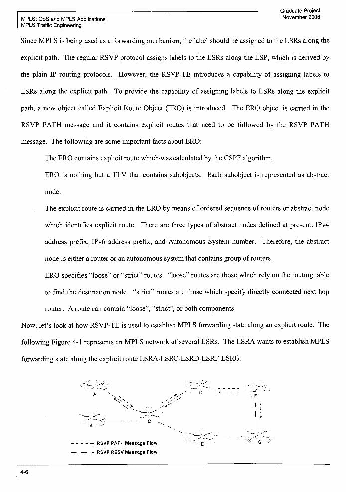
Graduate Project
MPLS: QoS and MPLS ApplicationsNovember 2006
MPLS Traffic Engineering
Since MPLS is being used as a forwarding mechanism, the label should be assigned to the LSRs along the
explicit path. The regular RSVP protocol assigns labels to the LSRs along the LSP, which is derived by
the plain IP routing protocols. However, the RSVP-TE introduces a capability of assigning labels to
LSRs along the explicit path. To provide the capability of assigning labels to LSRs along the explicit
path, a new object called Explicit Route Object (ERO) is introduced. The ERO object is carried in the
RSVP PATH message and it contains explicit routes that need to be followed by the RSVP PATH
message. The following are some important facts about ERO:
The ERO contains explicit route which was calculated by the CSPF algorithm.
ERO is nothing but a TLV that contains subobjects. Each subobject is represented as abstract
node.
The explicit route is carried in the ERO by means of ordered sequence of routers or abstract node
which identifies explicit route. There are three types of abstract nodes defined at present: IPv4
address prefix, IPv6 address prefix, and Autonomous System number. Therefore, the abstract
node is either a router or an autonomous system that contains group of routers.
ERO specifies"loose"
or"strict"
routes,"loose"
routes are those which rely on the routing table
to find the destination node,"strict"
routes are those which specify directly connected next hop
router. A route can contain "loose", "strict", or both components.
Now, let's look at how RSVP-TE is used to establishMPLS forwarding state along an explicit route. The
following Figure 4-1 represents an MPLS network of several LSRs. The LSRA wants to establish MPLS
forwarding state along the explicit route LSRA-LSRC-LSRD-LSRF-LSRG.
AN -v
- RSVP PATH Message Flow
- RSVP RESV Message Flow
4-6

Graduate Project
November 2006 MPLS: QoS and MPLS Applications
MPLS Traffic Engineering
Figure 4-1. LSP Setup using RSVP-TE
The whole process of establishing forwarding state can be effectively explained in six easy steps, which
are listed below.
(i) Construction of ERO: LSRA constructs ERO object that contains explicit path from LSRA to LSRG.
ERO contains subobjects or abstract node entries. Each subobject consists of IP address of each LSR
along the explicit path. Therefore, in our example, the ERO contains four abstract nodes or subobjects for
LSRC, LSRD, LSRF, and LSRG. Each subobject contains IP address of corresponding LSR.
(ii) Construction ofRSVP PATH message: LSRA builds RSVP PATH message and includes constructed
ERO and LABEL_REQUEST object.
(iii) Processing the ERO object at the source node: Before sending RSVP PATH message, LSRA
examines ERO that it has built in step (i). LSRA finds that the first entry (i.e. subobject or abstract node)
in the ERO is LSRC. LSRA finds the physical link/interface connected to LSRC and forwards the RSVP
PATH message on that link to LSRC.
(iv) Processing the ERO object at the intermediate node: LSRC receives the RSVP PATH message and
examines ERO contained in it. It finds itself as a first entry and LSRD as a next entry in the ERO. LSRC
finds a physical link directly connected to LSRD. Once the link is found, LSRC removes the subobject
associated with itself from ERO and forward the RSVP PATH message along with updated ERO to
LSRD. Updated ERO contains LSRD, LSRF, and LSRG.
LSRD examines the ERO in the incoming RSVP PATH message. LSRD finds next abstract node (i.e.
LSRF) in the ERO and finds physical link connected to that abstract node. Once the link is found, LSRD
updates the ERO by removing abstract node entry associated with it. LSRD sends the RSVP PATH
message along with updated ERO to LSRF. At this point, the updated ERO contains LSRF and LSRG.
4-7

Graduate Project
MPLS: QoS and MPLS Applications November 2006
MPLS Traffic Engineering
LSRF examines the ERO in the incoming RSVP PATH message. LSRF finds next abstract node (i.e.
LSRG) in the ERO and finds physical link connected to that abstract node. Once the link is found, LSRD
updates the ERO by removing abstract node entry associated with it. LSRF sends the RSVP PATH
message along with updated ERO to LSRG. At this point, the updated ERO contains only LSRG.
(v) Processing the ERO object at the destination node: Once LSRG receives the RSVP PATH message; it
finds itself as a last abstract node in the ERO. LSRG removes the ERO object and construct RSVP RESV
message along with the LABEL object. The LABEL object carries label value. This RSVP RESV
message is now transmitted to LSRF.
(vi) LSP setup: Once LSRF receives the RSVP RESV message, it extracts the label value from LABEL
object and populates in its routing table. LSRF assigns new label value in the LABEL object and sends
the RSVP RESV message to LSRD. Similar functions are followed at LSRD, LSRC, and LSRA. Once
the RSVP RESV message is received at LSRA, the LSP is established for the explicit route from LSRA to
LSRG.
4.1.2.2 CR-LDP
As discussed in Section 1, the LDP LABEL REQUEST messages and the LDP LABEL MAPPING
messages are used to assign labels to the LSRs across LSP. In order to establish forwarding state along
the explicit route, the CR-LDP supports Explicit Route (ER) object in the LABEL REQUEST message.
The ER object contains explicit route, which needs to be followed by the LABEL REQUEST message.
The characteristics ofthe ER object is similar to the ERO object discussed in RSVP-TE. The ER object
is a TLV inside the LABEL REQUEST message and it contains explicit routes in the form of subobjects
or abstract nodes.
Let's look at how CR-LDP establishes the MPLS forwarding state along the explicit route using the
following Figure 4-2.
4-8

Graduate Project
November 2006 MPLS: QoS and MPLS Applications
MPLS Traffic Engineering
? LDP LABEL REQUEST Message Flow gG
LDP LABEL MAPPING Message Flow
Figure 4-2. LSP Setup using CR-LDP
The whole process of establishing forwarding state can be effectively explained in six easy steps, which
are listed below.
(i) Construction of ER: LSRA constructs ER object that contains explicit path from LSRA to LSRG. ER
contains abstract node entries. Each abstract node consists of 32 bits IP address of each LSR along the
explicit path. Therefore, in our example, the ER contains four abstract nodes i.e. LSRC, LSRD, LSRF,
and LSRG.
(ii) Construction ofthe LABEL REQUEST message: LSRA builds the LABEL REQUEST message and
includes the constructed ER object in it.
(iii) Processing the ER object at the source node: Now, before sending the LDP REQUST message,
LSRA examines the ER object that it has built in step (i). LSRA finds that the first entry (i.e. subobject or
abstract node) in the ER is LSRC. LSRA finds the physical link/interface connected to the LSRC and
forwards the LDP REQUEST message on the link connected to the LSRC.
4-9

Graduate Project
MPLS: QoS and MPLS ApplicationsNovember 2006
MPLS Traffic Engineering
(iv) Processing the ER object at the intermediate node: LSRC receives the LABEL REQUEST message
and examines the ER object contained in it. It finds itself as a first entry and LSRD as a next entry in the
ER object. LSRC finds a physical link directly connected to the LSRD. Once link is found, the LSRC
removes the abstract node associated with itself from the ER object and forwards the LABEL REQUEST
message along with the updated ER object to the LSRD. The updated ER contains LSRD, LSRF, and
LSRG.
LSRD examines the ER in the incoming LABEL REQUEST message. LSRD finds next abstract node
(i.e. LSRF) in the ER and finds physical link connected to that abstract node. Once the link is found,
LSRD updates the ER by removing abstract node entry associated with it. LSRD sends the LABEL
REQUEST message along with the updated ER to the LSRF. At this point, the updated ER contains
LSRF and LSRG.
LSRF examines the ER contained in the incoming LABEL REQUEST message. LSRF finds next
abstract node (i.e. LSRG) in the ER and finds physical link connected to that abstract node. Once the link
is found, LSRD updates the ER by removing abstract node entry associated with it. LSRF sends the
LABEL REQUEST message along with the updated ER to the LSRG. At this point, the updated ER
contains only LSRG.
(v) Processing the ER object at the destination node: Once LSRG receives the LABEL REQUEST
message, it finds itself as a last abstract node in the ER. LSRG removes the ER object and construct the
LABEL MAPPING message along with the LABEL object. The LABEL object carries label value. This
LABELMAPPING message is now transmitted to the LSRF.
(vi) LSP setup: Once LSRF receives the LABELMAPPING message, it extracts the label value from the
LABEL object and populates in its routing table. LSRF assigns new label value in the LABEL object and
sends the LABELMAPPINGmessage to the LSRD. Similar functions are followed at LSRD, LSRC, and
LSRA. Once the LABEL MAPPING message is received at the LSRA, the LSP is established for the
explicit route from LSRA to LSRG.
4-10

Graduate Project
November 2006 MPLS: QoS and MPLS Applications
MPLS Traffic Engineering
4.1.2.3 Comparison ofCR-LDP and RSVP-TE
[i] LSP Establishment Method
Both, CR-LDP and RSVP-TE, use ordered LSP setup method to establish the LSP in the MPLS domain.
Ordered LSP setup method requires LSP establishment initiated from either ingress LSR or egress LSR
and propagates to the other end ofthe LSP. In the CR-LDP and the RSVP-TE, the ingress LSR initiates
establishment of the LSP along the explicit route.
[ii] Resource Reservation
RSVP already supports resource reservation along the LSP. The RSVP-TE adds functionality of
establishing the LSP along the explicit route and label assignment. The initial LDP protocol definitions
neither supported the resource reservation nor supported the establishment of LSP along the explicit
route. However, the CR-LDP supports both functions.
[iii] Scalability
CR-LDP is a hard state protocol. This means that the information is exchanged during the LSP
establishment time and then no additional information is exchanged until the LSP is not required. In
other words, no information exchange is required to make certain that connection between two peers is
active or not. Once it is determined that LSP is no longer needed, messages are exchanged between
network nodes to reclaim resources. Therefore, minimum bandwidth and CPU resources are held to
operate CR-LDP protocol.
4-11

Graduate Project
MPLS: QoS and MPLS Applications November 2006
MPLS Traffic Engineering
RSVP-TE is a soft state protocol. This means that once the LSP establishment is over, RSVP refresh
messages must be sent periodically between peers to make certain that connection is still alive. IfRSVP
refresh messages are not exchanged then the network nodes terminate the connections, delete the LSP,
and release the resources. Significant efforts were made to minimize the RSVP refresh traffic by
aggregating the RSVP refresh messages. Also, RSVP creates independent micro flow for each
application in the network. Therefore, it was believed that RSVP-TE does not provide scalability because
many thousands or more micro flows are required in big ISP networks. Several efforts were made to
aggregate micro flows to minimize scalability issue. However, scalability issue is not completely solved.
Also, due to RSVP refresh messages, more bandwidth requirement and CPU resources are needed to
process additional refresh traffic.
[iv] Security and Reliability
CR-LDP uses TCP/IP to communicate between LDP peers (except for discovery messages because LDP
uses UDP). The TCP/IP offers reliable and secure connection between the LDP peers. Also, the TCP/IP
offers timely error notification in case a communication problem occurs between the LDP peers. The
timely error notification will help to ensure proper and prompt action. As a result, the peer LSR can
perform immediate recovery actions by initiating required LDP messages.
RSVP-TE uses UDP/IP to communicate between peers. The UDP/IP connection is less secure and less
reliable than TCP/IP. Also, the connection failure between peers can only be detected when a peer stops
receiving RSVP refresh message. Since RSVP refresh message interval is varied from seconds to
minutes, the connection failure detection is not immediate and depends on RSVP refresh interval.
[v] Route Pinning
4-12

Graduate Project
November 2006 MPLS: QoS and MPLS Applications
MPLS Traffic Engineering
Route Pinning is an ability to force the established LSP to stay in place after setup. Once the LSP is
forced to stay in place, it should not be rerouted by preemption. In CR-LDP, the route pinning can only
take place at setup time since CR-LDP does not exchange any information after LSP establishment time.
In RSVP-TE, the route pinning can take place at any time by modifying RSVP PATH message because
the refresh messages are periodically sent to maintain reservation status.
4.2 Various Traffic Engineering Solutions
Does MPLS really solve the traffic engineering problem? This is a very important question as each ISP is
looking for an alternative to achieve true traffic engineering solution. As we discussed earlier in this
section, the main problem of traffic engineering is to make sure that the network utilization is optimum
and none of the links in the network remain underutilized or overutilized. If one segment in the network
goes overutilized then it contributes to congestion, which is experienced by customer as delay in online
transactions. At the same time the underutilized link is considered as lost in revenues for ISPs.
Therefore, the ISP wants to efficiently use the available bandwidth of the network in order to minimize
congestion and reduce operational costs to win the race in the competitive business market. The solution
to the problem of traffic engineering is to use effective routing mechanisms in the network. Service
provider can route the traffic evenly in the network; thus avoiding over utilization ofthe network segment
while the other network segment is underutilized.
4.2.1 Traffic Engineering Solution based on ATM OverlayModel
The overlay solution uses ATM or Frame Relay infrastructure at core and IP at the edge. The ATM and
Frame Relay switches are used in the core of a network while the IP routers are used as edge nodes.
Therefore, the ISP is using the routing functions provided by ATM or Frame Relay based virtual circuits
in the core. The following Figure 4-3 shows physical and logical layout of overlay model.
4-13

MPLS: QoS and MPLS Applications
MPLS Traffic Engineering
Graduate Project
November 2006
Physical Layout Logical Layout
Figure 4-3. ATM OverlayModel - Physical and Logical Layout
As per above Figure 4-3, the physical layout ofthe network contains layer 2 switches in the core and layer
3 routers at the edge. However, logically from the IP or layer 3 perspective, this is a mesh topology
where each router is just at one hop distance to the other router. Now, let's look at an example of how
routing capability ofATM switches can solve traffic engineering problem. The following Figure 4-4 is a
very well known"fish"
like topology.
Figure 4-4. Layer 2 TE Solution Example
4-14

Graduate Project
November 2006 MPLS: QoS and MPLS Applications
MPLS Traffic Engineering
In the above Figure 4-4, the RA, RB, and RC are routers while SA, SB, SC, SD, and SE are either ATM
or Frame Relay switches. All the network links have same capacity. The traffic originated from router
RA and RB are going to router RC. The capacity of traffic from RA to RC and RB to RC is less than the
available capacity of network links. To achieve traffic engineering by equally utilizing all links of the
network, two virtual circuits are created in network to carry the traffic from RA to RC and RB to RC.
Virtual circuit between RA and RC takes the path: RA-SA-SB-SC-SE-RC, while the virtual circuit
between RB and RC takes the path: RA-SA-SD-SE-RC. As a result, traffic from RA to RC and RB to
RC takes different routes in the core network made up of ATM or Frame Relay switches. In this
example, the traffic is evenly distributed over the network links and there is no over-utilization of any
network link. Even though the layer 2 solution looks satisfactory, it has some problems due to which this
solution is not convincing to the ISPs. Here are some problems associated with this solution:
Due to fixed ATM cell size, long data packets can not be accommodated into a single ATM cell.
Therefore, more ATM cells are required to fit in the long data packets. More ATM cells means
more overhead processing and more bandwidth requirements.
ATM/Frame Relay switches in the core changes the layer 3 router topology into mesh topology.
The existing IP routing protocol does not scale well in mesh topology.
The ATM/Frame Relay switches are expensive than IP routers. One of the goals ofMPLS is to
reduce network equipment costs by bringing the power of layer 2 switching by using layer 3
devices such as routers. Since ATM/Frame Relay switches are expensive compare to routers,
network designers want to avoid using them to keep the equipment cost as low as possible.
When ATM/Frame Relay switches are used in the core and the IP routers are used at the edge, the
network support team needs to support two networks in the real time. With the two networks in
place, the network management becomes very complex and extra training/operational activities
are involved to mange the network.
4-15

MPLS: QoS and MPLS Applications
MPLS Traffic Engineering
Graduate Project
November 2006
4.2.2 Traffic Engineering Solution based on IP Routing
In the current IP infrastructure, the routing is based on destination based routing mechanism where each
router ofthe network examines the destination IP address ofthe packet and forwards it to the next hop.
Also, the routing protocols being used by the traditional IP infrastructure are OSPF, RIP, and BGP.
These protocols use shortest path algorithm, which is based on the fewest number of hops in the network
topology and does not count on the bandwidth of the network. Therefore, many links in the network goes
underutilized, hi order to use all unused or underutilized links of the network, the load-balancing
approach or equal costmulti-path routing are used. But, in some cases the equal cost multi-path approach
does not work either.
To understand the problems with existing routing operations, we analyze a very basic network topology
as shown in the Figure 4-5 below.
NET1 1
Traffic = 100 Mbps xq.
Traffic = 100 Mbps &}
r*
NET2 B
r
The Best Path achieved by minimum hop count: C-D-G
OC-3-.._..-,'
.V E
Pa
jo.9.V
./NET3 X
* y
- - - - Congested Link
OC-3 = 155.52 Mbps
OC-12 = 622.08 Mbps
Figure 4-5. Layer 3 TE Solution Example 1
4-16
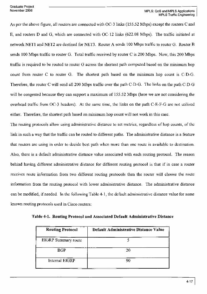
Graduate Project
November 2006 MPLS: QoS and MPLS Applications
MPLS Traffic Engineering
As per the above figure, all routers are connected with OC-3 links (155.52 Mbps) except the routers C and
E, and routers D and G, which are connected with OC-12 links (622.08 Mbps). The traffic initiated at
network NET1 and NET2 are destined for NET3. Router A sends 100 Mbps traffic to router G. Router B
sends 100 Mbps traffic to router G. Total traffic received by router C is 200 Mbps. Now, this 200 Mbps
traffic is required to be routed to router G across the shortest path computed based on the minimum hop
count from router C to router G. The shortest path based on the minimum hop count is C-D-G
Therefore, the router C will send all 200 Mbps traffic over the path C-D-G. The links on the path C-D-G
will be congested because they can support a maximum of 155.52 Mbps (here we are not considering the
overhead traffic from OC-3 headers). At the same time, the links on the path C-E-F-G are not utilized
either. Therefore, the shortest path based on minimum hop count will not work in this case.
The routing protocols allow using administrative distance to set metrics, regardless of hop counts, of the
link in such a way that the traffic can be routed to different paths. The administrative distance is a feature
that routers are using in order to decide best path when more than one route is available to destination.
Also, there is a default administrative distance value associated with each routing protocol. The reason
behind having different administrative distance for different routing protocol is that if in case a router
receives route information from two different routing protocols then the router will choose the route
information from the routing protocol with lower administrative distance. The administrative distance
can be modified, ifneeded. In the following Table 4-1, the default administrative distance value for some
known routing protocols used in Cisco routers:
Table 4-1. Routing Protocol and Associated Default Administrative Distance
Routing Protocol Default Administrative Distance Value
EIGRP Summary route 5
BGP 20
Internal EIGRP 90
4-17

MPLS: QoS and MPLS Applications
MPLS Traffic Engineering
Graduate Project
November 2006
IGRP 100
OSPF 110
IS-IS 115
RIP 120
Apart from the routing protocol, the administrative distance value of zero ("0") is assigned to the port or
interface directly connected to the router and administrative distance value of 1 is assigned to the static
route provided in the routing table. Based on the above default settings, if router receives route
information to the same destination from OSPF and RIP, the router will select information from OSPF
since it has lower administrative distance than RIP. The administrative distance can be changed in order
to let the router pick the route information from intended routing protocol.
In the following Figure 4-6, we have changed the administrative distance to modify the link metrics in
such a way that the best path will be C-E-F-G instead ofC-D-G.
(
"XNET1
The Best Path achieved by setting Administrative Distance: C-E-F-G
C
Traffic = 100 Mbps -%
Traffic = 100 Mbps ff>
NET2 13
OC-3
/ NET3
Q K
Congested Link
OC^3= 155.52 Mbps
OC-12 = 622.08 Mbps
Figure 4-6. Layer 3 TE Solution Example 2
We still have the links on the path C-E-F-G to be congested.
The other alternative we can think about is to distribute or share the traffic between router C and G over
two paths: C-E-F-G and C-D-G, as shown in the following Figure 4-7.
4-18

Graduate Project
November 2006 MPLS: QoS and MPLS Applications
MPLS Traffic Engineering
-^-v->~\Equal cost Multipath: Total Incoming traffic at C = 500 Mbps
NET1 ) Total traffic on path C-E-F-G = Total traffic on path C-D-G = 250 MbpsN )
A\CUTraffic = 200 Mbps \b
\
Traffic = 300 Mbps 0c;
/ NET2 :B
Q
<y~
S>c^
OC-3
c
F\Q.
A NET3 X
-V V
Congested Link
OC-3 =155.52 Mbps
OC-12 = 622.08 Mbps
Figure 4-7. Layer 3 TE Solution Example 3
Let's assume that router A is planning to send 200 Mbps traffic to router G and router B is planning to
send 300 Mbps traffic to router G. In this case, the router C will receive total of 500 Mbps traffic, which
needs to be distributed or shared over two paths to G. The path C-E-F-G will be required to transport 250
Mbps and the path C-D-G will be required to transport 250 Mbps. One or more links on both paths will
be congested.
So, no matter how hard the network engineer tries, there are always possibilities of some links get
overutilized or congested while the other links are underutilized. Also, as network deployed in the field is
very complex since there are so many routers and links involved. As a result, there are greater chances of
over utilization or underutilization of some part of the network. The main reason why IP can't solve the
traffic engineering problem is that it does not consider the available bandwidth as part of best path
algorithm.
4.2.3 Traffic Engineering Solution based on MPLS
4-19

Graduate Project
MPLS: QoS and MPLS Applications November 2006
MPLS Traffic Engineering
The MPLS uses constraint-based routing in order to support effective traffic engineering. With the use of
constraint-based routing, the explicit path is developed without violating a required constraint. The very
well known constraint is bandwidth so that congestion in the network can be avoided and the traffic can
be flowed with optimum use ofthe network links. The MPLS provides most ofthe functionality provided
by the overlay model which we discussed under Layer 2 solution. The functionality of overlay model is
provided in an integratedmanner with lower cost than currently available competitive solutions.
4.2.3.1 Traffic Trunks
MPLS provides traffic engineering by supporting routing of aggregated traffic rather than individual
traffic flow. This aggregation of traffic is called "Traffic Trunks".
The following are some characteristics of the traffic trunk:
Traffic trunk is an aggregation of traffic or individual traffic flows or micro flows.
Traffic in the traffic trunk traverses through the same common path.
Traffic in a given traffic trunk belongs to the same class of service.
Traffic trunks are routable objects.
Traffic trunk is unidirectional in nature. In the case when traffic between two nodes in the
supplier's network needs to be routed in both directions, two unidirectional traffic trunks can be
used. One traffic trunk going from source node to destination node is called forward trunk while
the other going from destination node to source node is called backward trunk. So, these two
trunks are associated with each other and they can not operate without each other. The
association of these trunks is called Bidirectional Traffic Trunk (BTT). If one trunk in the BTT
dies, the other dies automatically.
Each traffic trunk has various attributes associated with it. The traffic trunk attributes are
parameters which are assigned to that traffic trunk and influence trunk's behavior.
4-20

Graduate Project
November 2006 MPLS: QoS and MPLS Applications
MPLS Traffic Engineering
The common path is also known as a label switched path within a provider. The trunks are considered as
routable objects that are traversed through the LSPs. In this manner, the traffic trunks are similar to the
virtual circuits provided by ATM and Frame Relay network. The LSP used by traffic in a given traffic
trunk can be different in different provider's domain.
How many traffic trunks are required in the provider's network depends on provider's network topology
and not on howmuch amount of traffic the provider has to carry through his network. Since all the traffic
in a given traffic trunk is forwarded along the same path, the concept of traffic trunk removes the relation
between the traffic and the forwarding state plus the control traffic associated to develop the forwarding
state. As a result, increase in the traffic in the provider's network also increases the amount of traffic in
the traffic trunk but does not increase number of traffic trunks in the provider's network. On the contrary,
routing the traffic using individual micro flow increases the amount of forwarding state and the control
traffic required to establish the forwarding state. In addition, as traffic grows, the control traffic and
forwarding states will contribute to the higher bandwidth requirement and higher overhead in the
network. So, the routing based on traffic trunk scales well compare to individual flow.
Here are some of the basic operations carried over on a Traffic Trunk:
Establishment: To create an instance of traffic trunk.
Activation: To cause a traffic trunk to transport traffic.
Deactivation: To cause a traffic trunk to stop transporting traffic.
Modification ofAttributes: To cause an attribute of a traffic trunk to be modified.
Reroute ofTrunk: To cause a traffic trunk to change its route in case of link failure that carries a
traffic trunk.
Destroy: To destroy an instance of traffic trunk and release all resources associated with that
traffic trunk.
The following are the traffic trunk attributes:
4-21

Graduate Project
MPLS: QoS and MPLS ApplicationsNovember 2006
MPLS Traffic Engineering
Traffic parameter attributes: These attributes captures the characteristics of the FEC of the
traffic. Some of the characteristics are average rates, peak rates, and permissible burst size.
These parameters are important since they provide resource requirements of the traffic trunk.
Resource requirements very important to achieve traffic engineering.
Policing attributes: The policing attributes monitor traffic, control traffic, and ensure that only
valid traffic enters into the ingress node. It is desirable by many network operators to police at
the ingress node to achieve service level agreements. Therefore, from administrative perspective,
policing attributes are important for traffic trunk.
Generic path selection and maintenance attributes: These attributes define rules to select the path
or route taken by a traffic trunk as well as rules to maintain the paths that are already established.
As we know the path or route can be established by use of underlying routing protocols or by
administrator. If certain resources are required then the path selection is based on constraint-
based routing algorithm. If there are no specific resource requirements then path selection is
based on topology driven protocols such as IGP.
Priority attributes: These attributes are used to define the relative importance ofthe traffic trunks.
It identifies which traffic trunk is at higher priority than the other traffic trunk. These attributes
are very important in the constraint-based routing because they determine the order in which the
path selection procedure is done for the traffic trunk establishment time or when the fault occurs
in the network and the traffic trunk needs to be routed to other available path.
Preemption attributes: The preemption attributes determines whether a traffic trunk preempts
another traffic trunk or not. These attributes are very important since they ensure that higher
priority traffic trunks can always be routed through desired paths. There are four preempt modes
available for traffic trunk:
(i) Preemptor enabled: Traffic trunk with preemptor enabled mode turned on can
preempt lower priority traffic trunks with preemptable mode.
4-22

Graduate Project
November 2006MPLS: QoS and MPLS Applications
MPLS Traffic Engineering
(ii) Non-preemptor: Traffic trunk with non-preemptor mode turned on can not
preempt any other traffic trunks.
(iii) Preempt able: Traffic trunk with preemptable mode turned on can be
preemptable by any other higher priority traffic trunks.
(iv) Non-preemptable: Traffic trunk with non-preemptable mode turned on can not
be preemptable by any other traffic trunks.
Resilience attributes: Once the fault condition is observed in the network, the resilience attributes
detect the fault, notify the failure condition, recover the failure condition, and restore the services.
With the introduction of traffic trunk concepts, few problems are developed.
First problem is to determine how to measure the bandwidth of a particular traffic trunk.
Second problem is how to forward the traffic trunk over LSP.
There are various ways to achieve solution to the first problem. One of the solutions is to consider that
the traffic trunk requires zero bandwidth. Then, run the constraint based routing to route that traffic trunk
and the amount of traffic that traffic trunk supposed to carry on to the LSP. Now, measure the total data
rate flowing on to that LSP to find out the bandwidth requirement for that traffic trunk. Once the
bandwidth of all of the traffic trunks is known, it is important to make sure that the link, which will carry
all these traffic trunks, should have more bandwidth than the total bandwidth of all the traffic trunks.
Once this bandwidth constraint is met, it is also important to instruct which network links will carry the
traffic trunks. In order to meet this constraint,"colors"
can be associated with each link in the network.
The color information of a particular link can be carried by the attributes associated with that link. Once
the colors are assigned to each link, the traffic trunk can be instructed to avoid certain colors or to take
only certain colors while traversing through the network. So, these constraints can be used while
calculating the path in order to make sure that none ofthe required constraints is violated.
Forwarding Traffic Trunk overLSP
4-23

Graduate Project
MPLS: QoS and MPLS Applications November 2006
MPLS Traffic Engineering
The second problem is how to forward the traffic trunk over an LSP. MPLS provides a mapping of LSP
to the FEC to be local at the LSR. The aggregated traffic of a traffic trunk is usually assigned an FEC.
Therefore, the ability to forward the traffic trunk over the LSP is local to the LSR. This LSR is usually a
head end LSR since the constraint based routing requires head end LSR to set up LSP. A slightly
modified version of shortest path first algorithm can be used to forward the traffic trunk over LSP. With
plain SPF, the shortest path tree is developed and it provides outgoing interface and next hop information.
The slight modification to this algorithm is to check whether the new node added to the tree is a tail end
ofthe LSP or not. If it is a tail end ofthe LSP then that node is used as a"logical"
outgoing interface to
the destination of the traffic trunk in that network. One important assumption is made here which
indicates that LSPs should be pre-established using constraint based routing. To see how the modified
version ofthe SPF is working, let's look at the following Figure 4-8.
B, ", D
x.V
- - lspi x^C,
y
Figure 4-8. Traffic TrunkMapping to LSPs
4-24

Graduate Project
November 2006 MPLS: QoS and Mpls Applications
MPLS Traffic Engineering
As per the above Figure 4-8, two LSPs, LSP1 and LSP2, are established using constraint based routing
algorithm. So, for LSR-A, the"logical"
outgoing interface to network connected to LSR-D is LSP1 and
the"logical"
outgoing interface to network connected to LSR-F is LSP2. In other words, forLSR-A, the
network connected to LSR-D is reachable via LSP1 and the network connected to LSR-F is reachable via
LSP2. Once LSR-A starts to build its shortest path tree, it uses the plain SFP algorithm until it finds the
LSR-D. As soon as it adds LSR-D in its tree, LSR-A realizes that the LSR-D is a tail end ofthe LSP1.
Therefore, LSR-A makes the LSP1 as a"logical"
outgoing interface for all ofthe networks reachable via
LSR-D. If there is any other router connected to LSR-E then also the LSR-A considers LSP1 as a
"logical"
outgoing interface for all ofthe networks reachable via LSR-E. Similarly, the LSR-A makes the
LSP2 as a"logical"
outgoing interface for all of the networks reachable via LSR-F. This way, when a
traffic trunk is entering at LSR-A and has to reach to LSR-E then the LSR-A will instruct this traffic trunk
to take LSP1 in order to reach to LSR-E. Similarly, all the traffic trunks destined for LSR-F will take
LSP2. Traffic destined for the other LSRs will be forwarded using the shortest path tree routing table
which is built by using standard IGP processes.
4-25

Graduate Project
November 2006 MPLS: QoS and MPLs Applications
MPLS and ATM/Frame Relay
5 Introduction: ATM and Frame Relay
The Asynchronous Transfer Mode (ATM) and Frame Relay (FR) are Layer 2 technology used in Wide
Area Networks (WAN). Since the ATM and FR are very much deployed for WAN, it is sometimes
required that the MPLS packet may need to pass through the ATM network at some point. Also, ATM
and FR provide connection oriented services along with good QoS and TE functions. On the other side,
IP is a connection less but more flexible so that it is widely used in corporate networks and public
internet. MPLS combines the flexibility of IP and connection oriented approach from ATM and FR. Due
to its unique architecture, MPLS is seemed to be considered as an efficient network core technology.
However, the migrations of all core technologies to MPLS are not feasible overnight and require some
time. Therefore, carrying MPLS traffic over ATM or FR is an essential thing to achieve complete WAN
solution. Both ATM and FR carry the data from source to destination in some kind of virtual circuits.
We have seen in the previous sections that when the IP routers are connected to the ATM cloud or ATM
backbone, they create a logical mesh network of IP routers where each router is only next hop distance.
However, this creates a scaling problem. Therefore, when IP is overlaid on ATM network, if ATM
switches that creates the ATM backbone run both ATM and IP protocols then the scaling problem is
reduced a lot. Similarly, there is a need for the ATM switch to run MPLS protocol in order to transport
user data. However, there are some major issues on how to transport MPLS packet using layer 2 (ATM
or FR) delivery methods. Some of the issues are MPLS labels encoding to ATM or FR header, TTL
processing, and support ofMPLS label stack.
5.1 Main Forwarding Components for ATM and FR
Before we analyze how the issues related to MPLS and ATM/FR interoperation are resolved, it is
important to know some ofthe major components of ATM and FR that are being considered to support
MPLS.
5-1
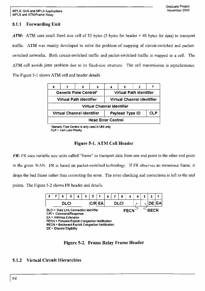
Graduate Project
MPLS: QoS and MPLS Applications November 2006
MPLS and ATM/Frame Relay
5.1.1 Forwarding Unit
ATM: ATM uses small fixed size cell of 53 bytes (3 bytes for header + 48 bytes for data) to transport
traffic. ATM was mainly developed to solve the problem of mapping of circuit-switched and packet-
switched networks. Both circuit-switched traffic and packet-switched traffic is mapped to a cell. The
ATM cell avoids jitter problem due to its fixed-size structure. The cell transmission is asynchronous.
The Figure 5-1 shows ATM cell and header details.
8 7 6 5 4 3 2 1
Generic FlowControl*
Virtual Path Identifier
Virtual Path Identifier Virtual Channel Identifier
Virtual Channel Identifier
Virtual Channel Identifier Payload Type ID CLP
Head Error Control
'Generic Flow Control is only used in UNI onlyCLP = Cell Loss Priority
Figure 5-1. ATM Cell Header
FR: FR uses variable size units called"frame"
to transport data from one end point to the other end point
in the given WAN. FR is based on packet-switched technology. If FR observes an erroneous frame, it
drops the bad frame rather than correcting the error. The error checking and corrections is left to the end
points. The Figure 5-2 shows FR header and details.
8 7 6 5 4 3 2 1 8 7 6 5 4 3 2 1
DLCI C/R EA DLCI/-^v
DE EA
DLCI = Data Link Connection Identifier
C/R = Command/Response
EA = Address Extension
FECN = Forward Explicit Congestion Notification
BECN = Backward Explicit Congestion Notification
DE = Discard Eligibility
FECN' ^BECN
Figure 5-2. Frame Relay Frame Header
5.1.2 Virtual Circuit Hierarchies
5-2
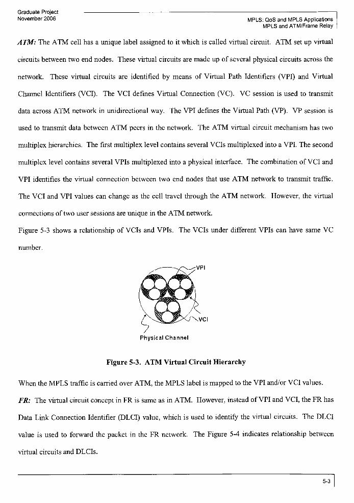
Graduate Project
November 2006 MPLS: QoS and MPLS Applications
MPLS and ATM/Frame Relay
ATM: The ATM cell has a unique label assigned to it which is called virtual circuit. ATM set up virtual
circuits between two end nodes. These virtual circuits are made up of several physical circuits across the
network. These virtual circuits are identified by means of Virtual Path Identifiers (VPI) and Virtual
Channel Identifiers (VCI). The VCI defines Virtual Connection (VC). VC session is used to transmit
data across ATM network in unidirectional way. The VPI defines the Virtual Path (VP). VP session is
used to transmit data between ATM peers in the network. The ATM virtual circuit mechanism has two
multiplex hierarchies. The first multiplex level contains several VCIs multiplexed into a VPI. The second
multiplex level contains several VPIs multiplexed into a physical interface. The combination ofVCI and
VPI identifies the virtual connection between two end nodes that use ATM network to transmit traffic.
The VCI and VPI values can change as the cell travel through the ATM network. However, the virtual
connections of two user sessions are unique in the ATM network.
Figure 5-3 shows a relationship of VCIs and VPIs. The VCIs under different VPIs can have same VC
number.
.VCI
Physical Channel
Figure 5-3. ATMVirtual CircuitHierarchy
When theMPLS traffic is carried over ATM, the MPLS label is mapped to the VPI and/or VCI values.
FR: The virtual circuit concept in FR is same as in ATM. However, instead ofVPI and VCI, the FR has
Data Link Connection Identifier (DLCI) value, which is used to identify the virtual circuits. The DLCI
value is used to forward the packet in the FR network. The Figure 5-4 indicates relationship between
virtual circuits and DLCIs.
5-3

- Graduate Project
MPLS: QoS and MPLS Applications November 2006
MPLS and ATM/Frame Relay
Figure 5-4. FRVirtual Circuit Hierarchy
When the MPLS traffic is carried over FR, theMPLS label is mapped to DLCI value.
5.1.3 Permanent Virtual Circuits (PVCs) and Switched Virtual Circuits (SVCs)
In both ATM and FR, the PVCs are setup on continuous bases while the SVCs are setup on an on-demand
basis. The PVC, once setup, is always available to the user whether the user needs it or not. While the
SVC is setup when the user needs it and is terminated when the user does not need it. In ATM, the
VPI/VCI value is reserved to setup a PVC or SVC, while in FR; the DLCI value is reserved to setup a
PVC or SVC.
5.2 MPLS Label Encoding in ATM and FR
The ATM switch has a"cross-connect"
table, which has several entries just like routing table. Each entry
consists of incoming port number and incoming VPI/VCI value to outgoing port number and outgoing
VPI/VCI value number. This"cross-connect"
table is similar to the LFIB (Label Forwarding Information
Base) in the MPLS network. Therefore, if the MPLS label is encoded to the VPI/VCI value then the
packet can easily be transmitted over the ATM. This mapping is only possible when the ATM switch is
upgraded to support MPLS protocol. The ATM switch, which is upgraded (by means of software
upgrade) to support MPLS, is called ATM-LSR. There are three methods for encoding MPLS label to
ATM VPI/VCI fields: (i) SVC encoding, (ii) SVP encoding, and (iii) SVP multipoint encoding. The
following Table 5-1 provides comparison of these three encodingmethods.
5-4

Graduate Project
November 2006 MPLS: QoS and MPLS Applications
MPLS and ATM/Frame Relay
Table 5-1. MPLS Label EncodingMethod for ATM
SVC Encoding SVP Encoding SVP Multipoint Encoding
Use both VPI and VCI fields to
encode the MPLS label.
Use both VPI and VCI fields to
encode the MPLS label.
Use both VPI and VCI fields to
encode the MPLS label.
Only the top label stack value is
encoded into the VPI/VCI fields.
The top label stack value is
encoded into the VPI field. The
second label value in the label
stack is encoded into the VCI
field.
The top label stack value is
encoded into the VPI field. The
second label value in the label
stack and the LSP ingress node is
encoded into the VCI field.
LSP is realized as ATM SVC and
LDP is realized as ATM
signaling protocol.
LSP is realized as ATM SVP and
LDP is realized as ATM
signaling protocol.
LSP is realized as ATM SVP and
LDP is realized as ATM
signaling protocol. Therefore,
ATM VP switching is possible.
ATM VP switching is not
supported.
The VPI can be used to support
ATM VP switching function at
ATM-LSR.
The ATM VP switching is
supported for multipoint-to-point
VPs.
ATM-LSR can not perform the
"push"
or"pop"
function on the
label stack.
ATM-LSR at the egress of VP
can do"pop"
function on the
label stack.
ATM-LSR at the egress of VP
can do"pop"
function on the
label stack.
This method can be used in any
network.
This method can not be used in
all networks because if ATM
virtual path is passed through a
non-MPLS network then the VPI
field is not necessarily available
This method can not be used in
all networks because if ATM
virtual path is passed through a
non-MPLS network then the VPI
field is not necessarily available
5-5

Graduate Project
MPLS: QoS and MPLS Applications November 2006
MPLS and ATM/Frame Relay
for use. for use.
There is a possibility that a router can receive a packet which is based on one encoding technique and the
same packet is leaving the router with different encoding technique. MPLS architecture does support the
packet that is received with a particular encoding technique but leaving the router with different label
stack encoding technique. However, ATM switches do not support this interoperability of encoding
technique. Therefore, when more than one ATM-LSR is consecutively involved to transmit packet then
the same encoding technique should be used in all ATM-LSRs.
In FR, the label is directly mapped to the DLCI value. However, the FR switch does not support the label
stack and Time To Leave (TTL) function that is provided by theMPLS packet.
5.2.1 Solution to TTL Processing
The ATM or FR switch forwards the cell or frame based on VPI/VCI (in ATM) or DLCI (in FR) values.
When MPLS packet is encapsulated into the ATM cell, only top label and the one label below in the label
stack are encoded into the VPI and VCI values. Similarly, the FR frame DLCI carries only top level label
of the label stack. The TTL parameter of the MPLS shim header is very important since it is designed to
prevent the packet from infinite loop. When a packet crosses one hop, the TTL value is decremented by
one. If the TTL value becomes zero and the packet is not yet reached to the destination then it is believed
that the packet is trapped into the loop and it is dropped from the network. However, the ATM or FR
does not examine the TTL parameter of the shim header. Therefore, a shim header, which carries the
TTL field, is directly inserted into ATM cell or FR frame after the VPI/VCI or DLCI field. Also, when
the shim header is inserted into ATM cell or into FR frame (at ingress ATM-LSR or FR-LSR) or the
MPLS packet is encapsulated into the ATM cell or FR frame, the TTL value is decremented by the
number of hops in the LSP. As we have seen in the previous sections, the LDP protocol is responsible to
count the number of hops of each LSP. At the egress ATM-LSR or FR-LSR, the ATM cell or FR frame
is being de-capsulate to MPLS packet and the TTL value is now available during the further processing of
5-6

Graduate Project
November 2006 MPLS: QoS and MPLS Applications
MPLS and ATM/Frame Relay
the packet. The processing of the MPLS packet over ATM backbone or FR backbone is quiet similar
except that in the first oneMPLS label is encoded into the VPI/VCI field while in the later one the MPLS
label is encoded into the DLCI field. The following example shows the MPLS over FR scenario.
5.3 Example: MPLS over FR
Since MPLS brings the advantages of IP and ATM/FR into one package, it is quite obvious that there is a
need to transport IP packet over MPLS network which uses ATM or FR as a delivery method. The
following Figure 5-5 indicates two IP networks are connected with FR network in the core. The FR
switches are updated to understand the MPLS packet and encapsulate the MPLS packet into a FR frame.
Therefore, the switch that uses the underlying Layer 2 technology (i.e. Frame Relay) to transport MPLS
packet is called as FR-LSR.
b
IP/MPLS
Domain
#1
N
B
MPLS/Frame Relay Network
\{
IP/MPLS
Domain"
'<
2
Ingress FR-LSR B:
-FEC assignment
-TTL processing
-Add label stack information
-Encapsulates MPLS packet into
FR frame
-Send FR frame to node C
FR-LSR C:
- Process the FR frame
And toward to node D
Egress FR-LSR D:
- De-encapsulate FR frame
and MPLS packet Forward
IP packet
-If label stack presents then
forward MPLS packet to next
LSR
Figure 5-5. IP/MPLS Packet overMPLS/FR Network
As per the above Figure 5-5, A and E are IP routers of different IP domains. B, C, and D are FR-LSRs.
Node B is also called as ingress FR-LSR and node D is also called as egress FR-LSR.
The packet goes through the following steps while traveling from A to E.
Steps at ingress FR-LSR (node B):
Packet arrives at node B. Node B classifies the packet to particular FEC.
The LFIB is examined and a shim header is inserted before IP header. This shim header contains
a label from the LFIB. If label stack is present then it will be inserted also.
5-7

Graduate Project
MPLS: QoS and MPLS Applications November 2006
MPLS and ATM/Frame Relay
The TTL value in the IP packet is examined and included in the TTL field of the shim header. If
there is a label stack then the TTL field is inserted into the shim header ofthe top label only.
Node B knows the LSP hop count which was calculated by LDP in advance. The TTL value is
decremented by the number ofhop counts that particular LSP contains.
TheMPLS packet is handed over to the OSI layer 2 for FR encapsulation.
FR encodes the top label into the DLCI number and a shim header with the decremented TTL
value is added after DLCI field.
The FR frame is sent to the node C.
Steps at intermediate FR-LSR (node C):
The DLCI value of incoming packet and the incoming port is examined. Once the associated
entry is found in the FR forwarding table and the outgoing DLCI/port combination is found, the
FR frame is forwarded to that outgoing port.
Steps at egress FR-LSR (node D):
When packet arrives at node D, the top label is popped.
If there are other lower labels exist (i.e. label stack), the packet is forwarded to the next hop (i.e.
node E) with proper encapsulation. If no label stack is present, the layer 3 information from the
IP packet is used to forward the packet to appropriate destination or next hop.
Before sending the packet to next hop, the TTL value is decremented appropriately.
Packet is now sent to node E.
5-8

Graduate Project
November 2006 MPLS: QoS and MPLS Applications
MPLS Virtual Private Network
6 Introduction: MPLS Virtual Private Network
In layman's term, the Virtual Private Network is a group of devices that are not bound to any physical
limits and at the same time provides high grade data security to the owner. The inception of any business
starts with one location and then spreads out to various geographic locations across the country or across
the world. If a company is located at one place then the local area network can be built and managed by
imposing local policies. Also, the security is also tightly handled in such a local area network. When
company spreads out to various geographic locations then the same level of security is warranted. One
way to handle the network spread out to various geographic sites is to deploy leased lines and manage
them. However, the companies want to cut the operational costs so they started using the public network
links. Some companies went beyond this step and outsourced the operations of their entire network. It is
very important to keep in mind that even though all the network operations are outsourced and the public
links are used, the major expectation of an intact security is still remain. There are various backbone
technologies available to provide VPN service. However, MPLS is expected to capture the major market
because it addresses major issues like scalability and traffic engineering. MPLS provides better handling
of these issues compared to layer 2 technologies like ATM and FR and layer 3 IP.
In order to provide security, the data is traveled through a secure tunnel called VPN tunnel. This tunnel
encapsulates the data at the source end of the network and de-capsulates at the destination end of the
network. While the data is traversing through the network it can not be hacked, playback, or modified.
Due to business demand, several organizations or companies tie with each other and make a group of
organizations. In such cases, VPN is not only limited to make intersite connectivity but VPN is also used
to connect group of organizations or companies. There are various topology options available to perform
intersite or intercompany connectivity. Due to growing dynamic nature of the work, the employees also
need to work remotely. The employees need to login into the company's network in order to perform
their work. Therefore, from usage perspective, two broad categories ofVPN are observed: Site-to-Site
6-1

MPLS: QoS and MPLS Applications
MPLS Virtual Private Network
Graduate Project
November 2006
VPN and Remote Access VPN. The site-to-site VPN is where two sites of the company connect to each
other by means ofVPN. The remote access VPN is where the employees are working remotely by means
of connecting to the company's VPN network. The VPNmainly follows one ofthe following topologies:
Mesh topology
Hub-Spoke topology
Mix ofMesh and Hub-Spoke topologies
If the dedicated links are providing more secure private network then why to use the public network?
Well, the main reason to use the public network is to reduce deployment cost, operational cost, and avoid
complete mesh of leased lines. With the use ofpublic network, the company's data can be compromised.
Therefore, the VPN concept has gained momentum because the VPN provides secure data connections.
Mesh Topology
In mesh topology, all VPN sites are connected to each other. For mesh topology, if public network is
used for the VPN links between sites, then the number of connections per site and the number of
dedicated links are lesser than the dedicated links between sites. Less number of dedicated links and the
less number of connections per site means less operational cost.
Public NetworfcXV8ite **
y(ISP Backbone Network))
^-^-/-^
(A) (B)
Figure 6-1. VPNMesh Topology
6-2

Graduate Project
November 2006 MPLS: QoS and MPLS Applications
MPLS Virtual Private Network
As per the Figure 6-1 (A), for 6 sites, the connections per site is 30. The number of dedicated links is 15.
However, this is the private network which is completely owned and managed by the company. If the
public network (i.e. ISP) is used then for n sites, the number of connections per site is always 1. As per
the Figure 6-1 (B), for 6 sites, the connection per site is 1. The number of dedicated links is 6.
Hub-Spoke Topology
In hub-spoke topology, one site is considered as a hub and all the other sites are considered as spokes. All
spoke sites are connected to hub site. There is no connectivity between two spoke sites. If the dedicated
links are used then again the number of connections per hub site is higher than ifpublic network is used.
/Site#1 \
\ /Site #3 j,Public Network A f (Spoke)y
(ISP Backbone Netvimrk))
(A) (B)
Figure 6-2. VPN Hub-Spoke Topology
As per the Figure 6-2 (A), the number of connections per hub site is 5 while as per Figure 6-2 (B), the
number of connection per hub site is 1 .
Partial Mesh Topology
The following Figure 6-3 illustrates the partial mesh topology.
\
(A) (B)
6-3

Graduate Project
MPLS: QoS and MPLS Applications November 2006
MPLS Virtual Private Network
Figure 6-3. VPN Partial Mesh Topology
As per Figure 6-3 (A), the number of connections per hub site is 3, per site #2 is 2, and per site #6 is 2.
As per Figure 6-3 (B), the number of connections per hub site, site #2, and site #6 can be reduced to 1 if
public network is used.
VPN brings several benefits to the big and distributed organizations. Some of them are listed below:
No need to reserve a public routable DP address. The non-routable private IP addresses are used
at the routers that are part ofVPN. (The non-routable private IP addresses are: 10.0.0.0 through
10.255.255.255, 172.16.0.0 through 172.31.255.255, 192.168.0.0 through 192.168.255.255)
Provides higher security while using public network links.
Provides geographically diverse sites to interconnect.
Reduces operational costs compared to traditionalWAN.
Allows to hire more remote employees; thus, reducing overhead costs associated with remote
employees.
Allows company to grow globally.
Allows company to certain complex network topologies such as the mesh topology.
6.1 VPNModels
There are two well known VPN models: Overlay Model and Peer Model. Each model is used for
different purposes and has its own pros and cons.
6.1.1 Overlay VPN Model
6-4

Graduate Project
November 2006 MPLS: QoS and MPLS Applications
MPLS Virtual Private Network
The overlay model is based on Layer 2 technologies such as ATM or FR. Sometimes, the point to point
dedicated links are also used. Basically, in the overlay model with ATM, FR, or leased line as backbone,
each site has the gateway device which is connected to the other sites by means of ATM circuits, FR
circuits, or leased lines. The gateway device is also called Customer Edge (CE) device. The network of
CE devices and the links connecting the CE devices is called virtual backbone. This virtual backbone
provides connection between the sites. The virtual backbone is mostly lying on top of the VPN service
provider's network. The service provider's network is made up of Service Provider Edge (PE) device and
Service Provider (P) device. The reason this model is called overlay model because the IP traffic from
each site is transmitted though the ATM/FR virtual circuits or tunnel in the core. The virtual circuit or
tunnel is built between CE to CE. The VPN service provider does not have any knowledge of the
addressing scheme associated with the VPN customer because Layer 3 routing information is not
exchanged between CE and PE routers. The forwarding ofthe customer traffic is done by means ofATM
VPI/VCI values or FR DLCI values and not by the IP routing information. Therefore, the overlay model
is also known as CE-CE model.
/Site#1 v) /'siten\
A Virtual Backbone 1( .
: )
/ \ iy~. -{^...GE.. i
>-Site #4A
Virtual circuitsSitemA
^_J~__y~~' ~^ K_/~~/
Figure 6-4. VPN OverlayModel
Some ofthe examples of overlay VPNs are those which are built using the following tunnels between CE
devices:
FR virtual circuits
ATM virtual circuits
6-5

Graduate Project
MPLS: QoS and MPLS Applications November 2006
MPLS Virtual Private Network
- IPSec tunnels
- GRE tunnels
Issues with Overlay VPNModel
(i)Management ofVirtual Backbone: In overlay model, the VPN customer is responsible to configure all
CE routers at different sites in order to establish virtual backbone connections between all sites. The
operational maintenance ofCEs requires a separate and dedicated staffwith certain amount of expertise in
LP routing and switching. If company requires proper QoS treatment and/or some traffic engineering
functions then the staff should be able to make sure that the services to the company is met according to
the demand. This becomes very challenging sometimes since multiple skills are required to meet
company's
growing needs.
(ii) VPN service cost: The other alternative to the management of virtual backbone problem is that ifVPN
service provider manages the virtual backbone for each company. However, this becomes very
challenging for VPN service provider in case if they need to manage thousands of virtual backbones.
Also, when VPN service provider needs to maintain so many virtual backbones, eventually it increases
cost ofthe VPN services.
(iii) Scalability: If VPN customer has hundreds of sites and all sites are connected with complete mesh
topology then the routing adjacencies is a problem. Each router in the overlay VPN model considers
other routers as directly connected or directly adjacent to it because the ATM or FR switches are invisible
at layer 3. Therefore, any update in the network topology will result in a router to send updates (or
routing information) to its neighbors. Therefore, adding one more site will require configuration updates
on all other sites as well as in a topology change events each router will exchange routing information. At
some point, the routing information traffic overloads the router and directly impacts the performance of
the routers. Therefore, the overlay model is not considered as a scalable approach.
6-6

Graduate Project
November 2006
6.1.2 Peer VPN Model
MPLS: QoS and MPLS Applications
MPLS Virtual Private Network
The peer model is mainly composed of CE, PE, and P routers. Unlike overlay model, the VPN customer
does not need to maintain the virtual backbone. The service provider backbone network will be used to
provide VPN services to the VPN customer. In peer model, the CE routers are directly interfacing to the
PE routers. The PE routers are connected via P routers in the core network. The following Figure 6-5
indicates the peer model for VPN.
VPN-A X
Site #lyv-
CE
J VPN-B ;
r Site #1A
^~v CE
y
ISP
X N
PE
/ t
A
PEA
PE
CE \
VPN-B
Site #2>
CE
( VPN-A
C. Site #2/
Figure 6-5. VPN Peer Model
The PE devices are aware of the network addressing scheme of the VPN customer. The customer data
traffic is routed according to the VPN customer network addressing schemes. The PE router and CE
router exchange route information with each other. One PE router can be connected to more than one CE
routers. Also, PE router can be connected to CE routers ofmore than one VPN customer. Unlike overlay
model, the CE routers at different sites of a VPN customer are not directly adjacent to each other.
Therefore, there is no routing adjacencies issue as we discussed in overlay model. The main reason to
call this VPN model as peer model is because from routing perspective, the customer network is peering
with the service provider network. The RIP, OSPF, BGP, or static routing is used for routing information
exchange between CE and PE routers. For routing information exchange between two PE routers or
between PE and P routers are done byMP-BGP or IGRP.
6-7

Graduate Project
MPLS: QoS and MPLS Applications November 2006
MPLS Virtual Private Network
MPLS can be used as a core tunneling protocol in overlay model as well as a peer model. However, the
peer model is mostly deployed using MPLS and BGP in the core service provider's network in order to
overcome the issues related to overlay model. Very well known MPLS VPN example is BGP/MPLS
Layer 3 VPN, where BGP is used to distribute routing information and MPLS is used as a forwarding
mechanism from one PE router to the other PE router.
Solutions to overlay model related issues
(i) Management of Virtual Backbone: In peer model, the VPN services are provided by the service
provider. The customer does not have to worry about end to end connectivity. VPN customer configures
the PE and P routers and connects to the VPN customer network. The VPN customer does not need to
worry about how their CE router at one site will establish and maintain connectivity with all other CE
routers at other sites. This reduces the operational costs to the VPN customer. Also, the peer model
allows the VPN service provider to provide services to diverse customers without knowledge of IP
routing.
(ii) VPN service cost: Once the service provider's core network is established, it can accommodate any
type of VPN customer. Unlike overlay model, the core network technology is not dependent on VPN
customer. The VPN service provider needs to maintain core network and update the capacity of network
in case more VPN customers are required to be handled. Adding one more site (i.e. one more CE router)
in the VPN customer network will require configuration changes in the directly connected PE router only
and not in any other CE routers. Since there are not so many complexities involved in regular
maintenance and operational activities, the VPN service cost to the customer is less compared to overlay
approach.
(iii) Scalability: In peer model, the problem related to routing adjacencies does no longer exist because
all CE routers of a particular VPN customer are peered with PE routers and not with the other CE routers.
Routing information is exchanged between directly connected CE and PE routers only.
6-8

Graduate Project
November 2006 MPLS: QoS and MPLS Applications
MPLS Virtual Private Network
Even though the"peer"
model looks more suitable since it addresses some of the very critical issues
related to"overlay"
model, the selection ofVPN model is completely based on several factors which are
described later in this section.
6.2 VPN Tunnel
As we have discussed before, the VPN tunnels are used to provide secure data communication between
customer sites. VPN tunnels can be setup between CE routers or between PE routers. Based on where
the VPN tunnels are setup, the VPN is identified as PE-based VPNs (where VPN tunnel is setup between
PE routers) or CE-based VPNs (where VPN tunnel is setup between CE routers). Some of the basic
requirements of tunnel are as follows:
it provides a virtual connection between sites.
it provides scalability so that growth in VPN numbers can be accommodated easily.
it provides security of data inside the VPN network so that one VPN customer can not have
access to the data of the otherVPN customer.
Sometimes the tunnel does not support encryption or authentication because the service provider takes
care of the security of the data. The VPN type in which the VPN customer trusts the VPN service
provider for the data integrity and security is called Trusted VPN. The VPNs with Frame Relay, ATM,
or BGP/MPLS backbone are examples of Trusted VPN. When a VPN is setup in such a way that the
customer data is encrypted and authenticated over the service provider's network then this type ofVPN is
called Secure VPNs. VPN with IPSec tunnel provisioned is called Secure VPN. MPLS LSP is also
called VPN tunnel because it encapsulates the IP traffic and transmits to destination. The following are
different VPN tunnel types:
[1] Generic Routing Encapsulation (GRE)
[2] Internet Protocol-Internet Protocol (IP-IP)
[3] IP Security (IPSec)
[4] Layer 2 Tunneling Protocol version 3 (L2TPv3)
6-9

MPLS: QoS and MPLS Applications
MPLS Virtual Private Network
Graduate Project
November 2006
[5] MPLS
The MPLS tunnel provides optimum support for all of the VPN tunnel requirements. The following
section provides brief information of all VPN tunnel types and focuses on the preference ofMPLS VPN
tunnel over other tunnel types.
[1] Generic Routing Encapsulation (GRE): GRE tunnels are established between CE devices in a VPN
network. The GRE tunnel is developed to transport multi protocol traffic between CE devices of a given
VPN. When any multi-protocol traffic is required to be tunneled using GRE, a GRE header is added to
that packet resulting in GRE packet. Now this GRE packet is again encapsulated in some other protocol
for delivery over VPN network. The following Figure 6-6 shows the packet with the GRE header.
GRE Header Data
1 2 3 4 5 6 7 8 1 2 3 4
r7 8 1 2 3 4 5 6 7 8 1 2 3 4 5 6 7
c R Ks S Recur A
Flags Version Protocol Type
Checksum (optional) Reserved (optional)
Key
Sequence Number
Figure 6-6. GRE Header
GRE tunnel provides only encapsulation and does not offer any security in terms of encryption.
However, GRE provides some level of authentication. GRE tunnel does not explicitly offer the
multiplexing of traffic, however, there is an extension on the GRE tunnel protocol that introduces a new
field called key field in the GRE header. This key field can be used to provide multiplexing capability in
GRE tunnel. So, the different traffic flow within a GRE tunnel can be assigned different key field
information. All the traffic flows with different key fields can be routed over the same GRE tunnel, thus,
providing multiplexing support in GRE tunnel.
6-10

Graduate Project
November 2006 MPLS: QoS and MPLS Applications
MPLS Virtual Private Network
[2] Internet Protocol-Internet Protocol (IP-IP): IP-IP tunnel is established between CE devices in a VPN
network. The IP-IP tunnel is developed to transport IP only traffic between CE devices of a given VPN.
IP-IP tunnel encapsulates and IP packet (with its own IP header) by adding an additional new IP header.
The following Figure 6-7 shows the packet with a new IP header.
New IP Header Old IP Header Data
Figure 6-7. Data Packetwith D?-D? Tunneling
The packet is forwarded within the VPN network by means of the new IP header which provides address
information of VPN entry point and VPN exit point. IP-IP tunnel does not provide multiplexing or
security capability. The service provider should use the IP access list feature on the routers to filter the IP
packets in order to provide security capability in VPN.
[3] IP Security (IPSec): IPSec consists of a set of protocols to provide security services to the IP traffic.
The IPSec tunnel is established by a router or a firewall, which is referred to as a security gateway. The
IPSec tunnel can be established between pair of hosts, a host or a security gateway, or pair of security
gateways. The security services are provided at layer 3. In VPN, the IPSec is usually built between CE
devices. The IPSec contains mainly two protocols, Authentication Header (AH) protocol and
Encapsulating Security Payload (ESP) protocol, in order to provide security services to IP traffic. AH
mainly provides connectionless integrity, data origin authentication mechanism, and anti-replay services,
while ESP mainly provides encryption mechanism. The EPSec assigns security services (also known as
"SecurityAssociation"
(SA)) to individual tunnels.
The IPSec operates in two modes: transport mode and tunnel mode. The transport mode provides
protection to the upper layer protocols such as TCP, ICMP, BGP, and UDP. In the tunnel mode, the
protection is applied to the tunneled IP packets. As shown in the Figure 6-8, in transport mode, the IPSec
security protocol header is added after IP header of the packet and before the higher layer protocol.
While in the tunnel mode, new IP header is inserted into the packet and the IPSec security protocol header
6-11

MPLS: QoS and MPLS Applications
MPLS Virtual Private Network
appears after the new IP header and before the original IP header ofthe packet.
Original IP Packet
..... .. .
:
Original IP
Header
TCP/UDP
Header
Data
Graduate Project
November 2006
IP Packet in
TransportMode
AH
Header
ESP
Header
TCP/UDP
Header
Data ESP
Trailer
IP Packet in
Tunnel Mode
New IP
Header
AH
Header
ESP
Header
Original IP
Header
TCP/UDP
Header
Data ESP
Trailer
Figure 6-8. EPSec Transport Mode and Tunnel Mode
In order to provide authentication, integrity, and encryption services, the IPSec supports separate set of
algorithms to put the cryptographic keys (that provides secret shared values between pair ofmachines) in
place by using manual or automatic distribution methods. Some of the automatic key distribution
methods are public key based approach (i.e. IKE) and Kerberos. While IPSec provides very good
security features, it does not provide support for multiplexed flows and traffic engineering alternatives.
Also, it does not provide any QoS support.
[4] Layer 2 Tunneling Protocol Version 3 (L2TPv3): The L2TPv3 tunnel carries the layer 2 protocols
(such as ATM, Frame Relay, HDLS, PPP, Ethernet) over layer 3 VPN. Therefore, the L2TPv3 tunnel is
used for layer 2 VPNs. The L2TPv3 uses two types ofmessages: control messages and data messages.
The control messages are responsible to establish, maintain, and clear the tunnel while the data messages
are responsible to encapsulate layer 2 frames over the tunnel. Control messages are supported with
reliable delivery mechanism while the data messages are not using reliable service ofL2TPv3. Therefore,
when packet loss occurs, the control messages are resent, while data messages are dropped. The
following Figure 6-9 shows the L2TPv3 header information.
L2TPv3 Header
(12 Bytes)
Layer 2 Frame
With Data
Tunnel Identifier
(4 Bytes)
Tunnel Cookie
(8 Bytes)
6-12
Graduate Project
November 2006 MPLS: QoS and MPLS Applications
MPLS Virtual Private Network
Figure 6-9. L2TPv3 Header
The L2TPv3 header contains two required fields: Tunnel ID and Session ID. The Tunnel ID indicates an
identifier for the control connection of L2TPv3 tunnel. The Tunnel ID may be different for different
receivers. Similar to Tunnel ID, the Session ID identifies session number within the L2TPv3 tunnel. The
Session ID may be different for different receivers. The Tunnel ID and Session ID are provided by the
receiver to the sender. Therefore, when sender sends layer 2 frames to receiver, it places Tunnel ID and
Session ID in the packet. Since the Tunnel ID and Session ID fields are placed by the sender, multiple
Session IDs for a given Tunnel ID can be specified to multiplex the layer 2 frames in a given L2TPv3
tunnel. However, the L2TPv3 tunnel does not provide security and QoS.
[5] MPLS: The MPLS tunneling is provided by establishment of LSPs between PEs within the service
provider's network. Since it is already discussed how MPLS works in the previous sections, here are the
list ofthe benefitsMPLS tunnel is providing over different VPN tunnel types:
(i) Traffic Engineering: Different VPN customers have different bandwidth requirements. As we have
already seen in the MPLS TE section, the MPLS provides greater traffic engineering capabilities. If
MPLS tunnel is used then the service provider can satisfy bandwidth requirement for any VPN customer.
(ii) Multiplexing: The MPLS supports label stacking mechanism. More than one label is supported in
label stacks. MPLS switches packets based on top label on the label stack only. Therefore, more than
one LSPs can be multiplexed in a single LSP tunnel inside service provider's network. In addition, this
capability also gives scalable environment to the service provider. Therefore, the optimum use of
resources can be achieved.
(iii) Security: MPLS provides security services similar to the layer 2 ATM or FR network. In MPLS
tunnel, the security is mainly provided by using different label stacks for different customers. As a result,
traffic for one VPN customer will be routed based on the label stack information unique for that VPN
customer only. There is no way for the one VPN customers to intercept the sensitive data of the other
VPN customer if label stack is used. However, there is a security related concern insider the service
6-13
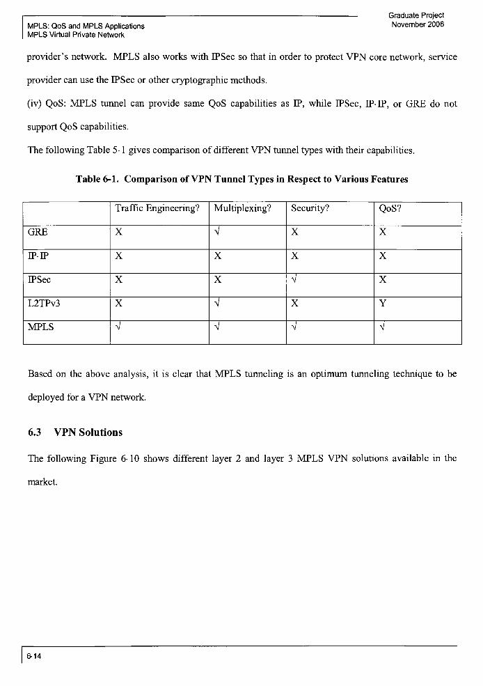
MPLS: QoS and MPLS Applications
MPLS Virtual Private Network
Graduate Project
November 2006
provider's network. MPLS also works with IPSec so that in order to protect VPN core network, service
provider can use the IPSec or other cryptographic methods.
(iv) QoS: MPLS tunnel can provide same QoS capabilities as IP, while IPSec, IP-IP, or GRE do not
support QoS capabilities.
The following Table 5-1 gives comparison of different VPN tunnel types with their capabilities.
Table 6-1. Comparison ofVPN Tunnel Types in Respect to Various Features
Traffic Engineering? Multiplexing? Security? QoS?
GRE X V X X
IP-IP X X X X
IPSec X X V X
L2TPv3 X V X Y
MPLS V V V V
Based on the above analysis, it is clear that MPLS tunneling is an optimum tunneling technique to be
deployed for a VPN network.
6.3 VPN Solutions
The following Figure 6-10 shows different layer 2 and layer 3 MPLS VPN solutions available in the
market.
6-14

Graduate Project
November 2006 MPLS: QoS and MPLS Applications
MPLS Virtual Private Network
VPWS
Virtual Private
Network
Layer 2
IPLS
Layer 3
RFC4364/
2547 bis based
Figure 6-10. Virtual Private Network Solutions at Layer 2 and Layer 3
This subsection will provide an overview of each MPLS VPN solution and draw a conclusion on which
MPLS VPN solution (layer 2 or layer 3) is better in what condition by comparing the solutions. In
general, the selection ofthe MPLS VPN solution is mainly based on the VPN customer's requirements,
the network architecture, how much VPN customer can afford to receive VPN service, type of VPN
service offerings, and how mature the MPLS VPN solution is. In order to compare different MPLS VPN
solutions, the following ones or more of the deciding factors will be analyzed with each MPLS VPN
solution.
Resource requirements (or QoS) ofVPN customer
Type of traffic VPN customer is willing to transport between sites
Operational cost associated with VPN service (for VPN customer)
Type of security available to VPN customer
Scalability (main deciding factor for service provider)
Operational cost associatedwith VPN solution (for service provider)
Adaptability to offer new services to VPN customer
6-15

Graduate Project
November 2006MPLS: QoS and MPLS Applications
MPLS Virtual Private Network
6.3.1 Layer 2 MPLS VPN Solution
In layer 2 MPLS VPN solutions, the layer 2 traffic (i.e. ATM, Frame Relay, and Ethernet) is carried over
MPLS tunnels. The MPLS tunnel is established between edge PE routers. The layer 2 MPLS VPN
solutions are mainly following the"overlay"
VPN model which we discussed before. The layer 2
solution is further focusing on two categories: point-to-point connection or multi-point connection. The
main component of layer 2 MPLS VPN solution is a Virtual Circuit (VC) that is connected between
customer's two CE routers. The layer 2 frames are carried across the MPLS network by means ofVCs.
The MPLS is used as a backbone technology and carries the customer traffic (i.e. VCs) from one site to
the other site. An MPLS LSP is built between two edge PEs and the VCs carrying customer's traffic are
carried over this LSP. The VCs are in fact LSPs only and are carried inside the main LSP. This behavior
of LSPs inside LSP can be established by means of label stack. As per the Martini Draft, there are two
labels included in the packet that are traveling acrossMPLS backbone. A label that is used to forward the
MPLS packet from one source PE router to the destination PE router is called "tunnel label". The other
label is used to identify the destination site address that is connected directly to the destination PE router.
The following Figure 6-1 1 shows the header ofthe packet traveling throughMPLS backbone.
1VPN
( Customer~
f-
Site #1 CE1 PE1xn.
MPLS
P1
Layer 2 FrameVC
Laret
Tunnel
Label
y-,. f
H^PE2
VPN
-
rp2Customer
-J
""
i Site #2 \(
Figure 6-11. MPLS Packet in Layer 2 MPLS VPN Solution
It is important to note that the VC is unidirectional. In order to allow bi-directional traffic between site #1
and site #2, a pair ofunidirectional VCs are required.
Virtual PrivateWire Service (VPWS)
6-16

Graduate Project
November 2006 MPLS: QoS and MPLS Applications
MPLS Virtual Private Network
Service providers network is behaving as an emulating circuits or pseudo wires between the customer
sites. The VPN customer does not need to make any changes to its existing ATM or FR connections
since the connection between CE and PE is not changed in VPWS. The CE router performs layer 2
switching in order to decide at which site the data should be sent to. The PE router assigns the traffic
from a customer site to an LSP and sends this LSP across a big LSP that is connected between two edge
PE routers.
VPWS provides point-to-point connectivity between customer sites.
- Since MPLS is used as a core networking technology, any service provider withMPLS service offering
can provide VPWS connections to the customer site. This helps to save a good amount of money to
service providers who want to use their existing IP/MPLS backbone to support the customer with ATM
and FR connections.
Who can be benefited with this solution?
The main benefit goes to service provider who has only MPLS backbone and needs to support customer
with ATM and FR services. Also, if a VPN customer has hub and spoke configuration then VPWS
provides a point-to-point connectivity using MPLS backbone without changing any connections to the
VPN customer site.
Virtual Private LAN Service (VPLS)
- Service provider's network is considered as a big LAN switch or bridge in order to extend the Ethernet
LAN reach to various customer sites.
- VPLS provides multi-point connection to the VPN customer. In other words, all sites of a VPN
customer appear to be connected to each other by means ofLAN switch or bridge.
The PE devices read MAC addresses in order to decide the destination PE device. Therefore, very
complicated task is for the PE devices to learn about the MAC address for all other PE routers in the
MPLS domain. This task is similar to what Ethernet switch performs in order to learn the MAC address
of each connected devices. BGP or LDP protocol can be used to perform auto-discovery ofthe other PE
6-17

Graduate Project
MPLS: QoS and MPLS Applications November 2006
MPLS Virtual Private Network
devices in order to setup pseudo links.
- The PE devices are required to have more memory and processing power since it needs to maintain LSP
tunnels, to establish pseudo wires, and to learn and store MAC addresses. Also, due to limitation ofMAC
learning algorithms, the VPN customer with hundreds of VPN sites can not be supported with VPLS
solution.
Who can be benefitedwith this solution?
This solution is useful to the customers with the sites in metro area or campus areas.
Internet Protocol LAN Services (TPLS)
- In VPSW and VPLS solutions, the CE device was believed to be any layer 2 device. However, in case if
the CE device is a IP router then the IPLS VPN solution will be used.
In IPLS solution, the edge PE devices read the layer 2 header information inside the IP packet it
received from the CE router in order to make the forwarding decision inside the MPLS backbone
network. Therefore, the IPLS solution is called layer 2 MPLS VPN solution.
- IPLS provides multi-point connections.
- In IPLS, the PE devices do not need higher memory and processing power since they need to maintain
LP addresses andMAC addresses of connected CE devices only. Also, the IPLS scales well compared to
VPLS solution.
6.3.2 Layer 3 MPLS VPN Solution
There are two main layer 3 MPLS VPN solutions available: RFC 4364/2547 bis based (or BGP/MPLS)
and Virtual Router based. The BGP/MPLS solution is very popular since it is highly scalable and once
configured then it is easy to maintain. The layer 3 MPLS VPN solutions follow peerVPN model.
RFC 4364/2547 bis based solution (BGP/MPLS)
- In this VPN solution, the IPv4 traffic is transmitted byMPLS tunnel across the service provider's MPLS
backbone network.
6-18

Graduate Project
November 2006MPLS: QoS and MPLS Applications
MPLS Virtual Private Network
Routing information between CE router and PE router is exchanged by means ofE-BGP, OSPF, RIP, or
static routing. The routing information between PE-P routers and P-P routers is exchanged by using
BGP.
One edge PE router can be connected to more than one CE routers of different VPN customers. The
VPN customers can use the non-routable private IP addresses at CE routers of different sites. Therefore,
in order to distinguish one VPN customer from the other, VPN customer specific routing table are
established and maintained in each PE router. These routing tables are called Virtual Routing and
Forwarding tables (VRF). PE router maintains VRF for each VPN customer.
- BGP is used to distribute routing information inside the MPLS backbone network. BGP assumes that
the LP addresses are unique for each VPN customer. However, this assumption is incorrect because more
than one VPN customers may use the same non-routable IP address. Therefore, a new LP address called
VPN-LP address is introduced. The VPN-IP address is generated by adding a fixed-length field called
Route Distinguisher (RD) to the LP address. The RD consists: type+AS number+Assigned number. The
RD number generated by each service provider is unique because it contains AS number which is globally
unique for any service provider. Therefore, the VPN-IP address is always unique.
- This solution is a highly scalable because there is no routing adjacency between CE routers. Also, this
solution provides any to any connection. Therefore, adding more sites for a VPN customer is not a big
deal and just a matter of adding an entry into the VRF at the directly connected edge PE router.
- Since there are different VRFs for different VPN customer and different LSPs are assigned for different
VPN customers, it is impossible that one VPN customer's data leaks to the other VPN customers.
Who can be benefited with this VPN solution?
This solution is widely deployed by many service providers because this solution brings higher
scalability, higher security, and low operational cost to the service provider.
Virtual Router Based
6-19

Graduate Project
MPLS: QoS and MPLS Applications November 2006
MPLS Virtual Private Network
- Each PE routers contains series of virtual routers. Virtual routers in a physical router share memory and
processor power of a physical router. Each virtual router corresponds to the virtual routing table (or VRF)
of a VPN customer. Each virtual router acts as an independent router, thus, it has all functionality that a
router should have.
The virtual routers that are part of same VPN are connected with each other by means of a secure tunnel.
Therefore, there are multiple tunnels established between two PE routers which contain series of virtual
routers. Unlike the MPLS/BGP solution, the route information between two virtual routers and
associated CE routers is performed independently from the other virtual routers.
- Since all virtual routers participating in a VPN should establish separate tunnels to each other, a full
mesh topology is established. The full mesh topology contributes to scalability issue. Therefore, the
MPLS/BGP is more scalable than VR based solution.
6-20

Graduate Project
November 2006 MPLS: QoS and MPLS Applications
MPLS/BGP VPN Implementation
7 MPLS/BGP VPN Implementation
In this section, MPLS/BGP layer 3 VPN has been implemented. This solution is based on RFC 4364.
The following figure indicates a test configuration that has been implemented in the following sections.
Layer 3 MPLS VPN
Customer A, Site-i
AS# 65001X)VRF100 \
E0/0: J1CC100.100.1j24
A?CEt'
\S1fl.1: 192. 168 <0.1/30
Customer A, Site-2 }
AS# 65001
VRF100
E0/O: 1IWM200.1
AXE2
SO/0.1: 192.168.0.13/30/
SO/0.1: 192.i68.rj.2i30 *&<*.
->> ISP
/S0/O.1: 92.168.0.14/30
SO/0.2: 192/68.0.6/30
SO/0.1: 192.168.0.5/30
b-ceL
AS# 65002 ._&rji.*J
PE2
E0J0.TO.100.100.1/24
JCustomer B, Site-1^AS# 65003
V__. VRF200V
*-
0^"
.y#
A\ SO/0.2: 192.168.0.18)30
\
S0.1: 192.168.0.17/3fj\
B-CE2
E0: 10.100.2WTiJ24 V
^Customer B, Site-2A>- AS# 65003 J
VRF200/-
Figure 7-1. Layer 3 MPLS/BGP VPN Configuration
7-1

Graduate Project
MPLS: QoS and MPLS Applications November 2006
MPLS/BGP VPN Implementation
Router Configuration for A-CE1:
A-CEl#show run
Building configuration...
Current configuration 133 4 bytes
i
version 12.2
service timestamps debug datetime msec
service timestamps log datetime msec
no service password-encrypt ion
i
hostname A-CE1
i
logging queue -limit 10 0
i
memory-size iomem 10
ip subnet -zero
mpls ldp logging neighbor-changes
no voice hpi capture buffer
no voice hpi capture destination
mta receive maximum-recipients 0
interface Ethernet0/0
description IP related information for LAN interface
ip address 10.100.100.1 255.255.255.0
no ip redirects
no ip proxy-
arp
no ip mroute-cache
half -duplex
i
interface Seriall/0
no ip address
encapsulation frame-relayno fair-queue
i
interface Seriall/0. 1 point-to-point
ip address 192.168.0.1 255.255.255.252
frame-relay interface-dlci 301
i
interface Seriall/1
no ip address
shutdown
l
interface Seriall/2
7-2

Graduate Project
November 2006MPLS: QoS and MPLS Applications
MPLS/BGP VPN Implementation
no ip address
shutdown
I
interface Seriall/3
no ip address
shutdown
i
interface FastEthernet2/0
no ip address
shutdown
duplex auto
speed auto
i
router bgp 650 01
no synchronization
bgp log-neighbor-changes
bgp dampeningnetwork 10.100.100.0 mask 255.255.255.0
neighbor 192.168.0.2 remote-as 65002
neighbor 192.168.0.2 timers 15 45
noauto-
summary
ip http server
ip classless
call rsvp-sync
mgcp profile default
dial -peer cor custom
line con 0
line aux 0
line vty 0
end
A-CE1#
A-CEl#show ip bgp summary
BGP router identifier 192.168.0.1, local AS number 65001
BGP table version is 3, main routing table version 3
2 network entries using 202 bytes of memory
2 path entries using 96 bytes of memory
2 BGP path attribute entries using 12 0 bytes of memory
1 BGP AS-PATH entries using 24 bytes of memory
0 BGP route-map cache entries using 0 bytes of memory
0 BGP filter-list cache entries using 0 bytes of memory
BGP using 442 total bytes of memory
Dampening enabled. 0 history paths, 0 dampened paths
BGP activity 2/0 prefixes, 2/0 paths, scan interval 60 sees
7-3

Graduate Project
MPLS: QoS and MPLS Applications November 2006
MPLS/BGP VPN Implementation
Neighbor V AS MsgRcvd MsgSent TblVer InQ OutQ Up/Down State/PfxRcd
192.168.0.2 4 65002 392 392 3 0 0 01:36:46 1
A-CE1#
A-CEl#show ip bgp nei 192.168.0.2 rou
BGP table version is 3, local router ID is 192.168.0.1
Status codes: s suppressed, d damped, h history, *valid, > best, i internal,
r RIB-failure, S Stale
Origin codes: i IGP, e EGP. ? incomplete
Network Next Hop Metric LocPrf Weight Path
*> 10.100.200.0/24 192.168.0.2 0 65002 65002 i
Total number of prefixes 1
A-CE1#
A-CE1#
A-CEl#show ip bgp nei 192.168.0.2 ad
A-CEl#show ip bgp nei 192.168.0.2 advertised-routes
BGP table version is 3, local router ID is 192.168.0.1
Status codes: s suppressed, d damped, h history, *valid, > best, i internal,
r RIB-failure, S Stale
Origin codes: i IGP, e EGP, ? incomplete
Network Next Hop Metric LocPrf Weight Path
*> 10.100.100.0/24 0.0.0.0 0 32768 i
A-CE1#
A-CE1#
Router Configuration for A-CE2:
A-CE2#show run
Building configuration.
Current configuration : 1212 bytes
I
version 12.2
service timestamps debug datetime msec
service timestamps log datetime msec
no service password-encryption
j
hostname A-CE2
i
logging queue-limit 100
I
memory-size iomem 10
ip subnet -zero
mpls ldp logging neighbor-changes
no voice hpi capture buffer
no voice hpi capture destination
7-4
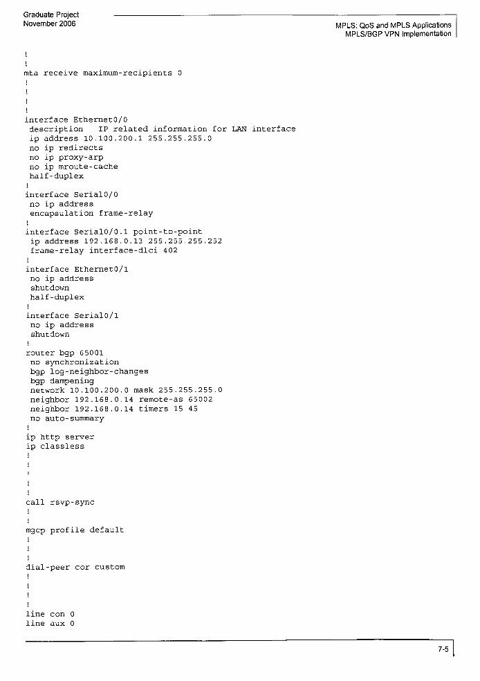
Graduate Project
November 2006 MPLS: QoS and MPLS Applications
MPLS/BGP VPN Implementation
i
mta receivemaximum-
recipients 0
interface EthernetO/0
description IP related information for LAN interface
ip address 10.100.200.1 255.255.255.0
no ip redirects
no ipproxy-
arp
no ip mroute-cache
half -duplex
i
interface Serial0/0
no ip address
encapsulation frame-relayi
interface Serial0/0.1 point-to-point
ip address 192.168.0.13 255.255.255.252
frame-relay interface-dlci 402
i
interface EthernetO/l
no ip address
shutdown
half -duplex
i
interface Serial0/l
no ip address
shutdown
i
router bgp 65001
no synchronization
bgp log-neighbor-changes
bgp dampeningnetwork 10.100.200.0 mask 255.255.255.0
neighbor 192.168.0.14 remote-as 65002
neighbor 192.168.0.14 timers 15 45
noauto-
summaryi
ip http server
ip classless
l
call rsvp-sync
i
mgcp profile default
dial-peer cor custom
i
!
I
I
line con 0
line aux 0
7-5
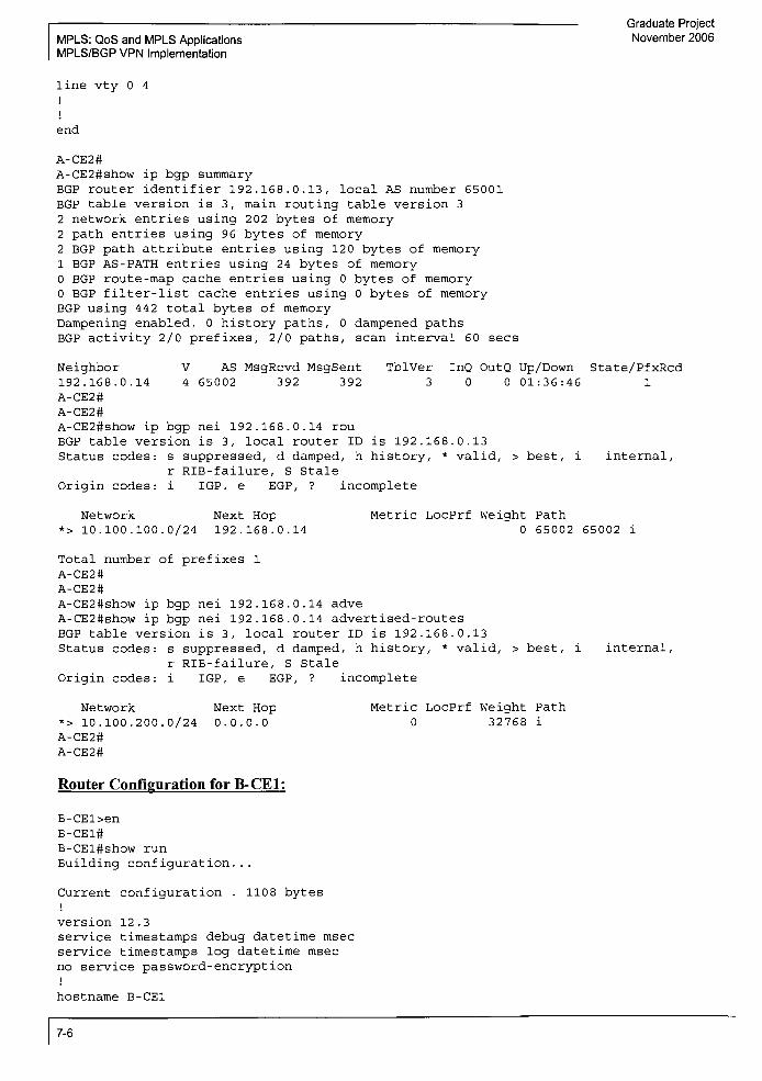
MPLS: QoS and MPLS Applications
MPLS/BGP VPN Implementation
Graduate Project
November 2006
line vty 0 4
end
A-CE2#
A-CE2#show ip bgp summary
BGP router identifier 192.168.0.13, local AS number 65001
BGP table version is 3, main routing table version 3
2 network entries using 2 02 bytes of memory
2 path entries using 96 bytes of memory
2 BGP path attribute entries using 120 bytes of memory
1 BGP AS-PATH entries using 24 bytes of memory
0 BGP route-map cache entries using 0 bytes of memory
0 BGP filter- list cache entries using 0 bytes of memory
BGP using 442 total bytes of memory
Dampening enabled. 0 history paths, 0 dampened paths
BGP activity 2/0 prefixes, 2/0 paths, scan interval 60 sees
V AS MsgRcvd MsgSent TblVer InQ OutQ Up/Down State/PfxRcd
4 65002 392 392 3 0 0 01:36:46 1
Neighbor
192.168.0.14
A-CE2#
A-CE2#
A-CE2#show ip bgp nei 192.168.0.14 rou
BGP table version is 3, local router ID is 192.168.0.13
Status codes: s suppressed, d damped, h history, *valid, > best, i internal,
r RIB-failure, S Stale
Origin codes: i IGP. e EGP, ? incomplete
Network Next Hop*> 10.100.100.0/24 192.168.0.14
Metric LocPrf Weight Path
0 65002 65002 i
Total number of prefixes 1
A-CE2#
A-CE2#
A-CE2#show ip bgp nei 192.168.0.14 adve
A-CE2#show ip bgp nei 192.168.0.14 advertised-routes
BGP table version is 3, local router ID is 192.168.0.13
Status codes: s suppressed, d damped, h history, *valid, > best, i
r RIB-failure, S Stale
Origin codes: i IGP, e EGP, ? incomplete
internal,
Network
*> 10.100.200.0/24
A-CE2#
A-CE2#
Next Hop
0.0.0.0
Metric LocPrf Weight Path
0 32768 i
Router Configuration for B-CE1:
B-CEl>en
B-CE1#
B-CEl#show run
Building configuration...
Current configuration . 1108 bytes
!
version 12.3
service timestamps debug datetime msec
service timestamps log datetime msec
no service password-encryption
i
hostname B-CE1
7-6
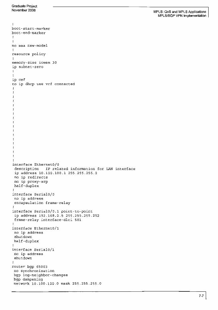
Graduate Project
November 2006MPLS: QoS and MPLS Applications
MPLS/BGP VPN Implementation
boot-start -marker
boot -
end-marker
i
i
no aaa new-model
I
resource policy
!
memory-size iomem 3 0
ip subnet -zero
ip cef
no ip dhcp use vrf connected
interface Ethernet0/0
description IP related information for LAN interface
ip address 10.100.100.1 255.255.255.0
no ip redirects
no ipproxy-
arp
half -duplex
I
interface Serial0/0
no ip address
encapsulation frame-relayj
interface Serial0/0.1 point-to-point
ip address 192.168.0.5 255.255.255.252
frame-relay interface-dlci 501
i
interface Ethernet0/1
no ip address
shutdown
half -duplex
i
interface Serial0/1
no ip address
shutdown
i
router bgp 65003
no synchronization
bgp log -neighbor-changes
bgp dampeningnetwork 10.100.100.0 mask 255.255.255.0
7-7

Graduate Project
MPLS: QoS and MPLS Applications November 2006
MPLS/BGP VPN Implementation
neighbor 192.168.0.6 remote-as 65002
neighbor 192.168.0.6 timers 15 45
noauto-
summary
ip http server
ip classless
control -plane
line con 0
1 ine aux 0
line vty 0
end
B-CE1#
B-CE1#
B-CEl#show ip bgp summary
BGP router identifier 192.168.0.5, local AS number 65003
BGP table version is 3, main routing table version 3
2 network entries using 234 bytes of memory
2 path entries using 104 bytes of memory
3/2 BGP path/bestpath attribute entries using 372 bytes of memory
1 BGP AS-PATH entries using 24 bytes of memory
0 BGP route-map cache entries using 0 bytes of memory
0 BGP filter-list cache entries using 0 bytes of memory
BGP using 734 total bytes of memory
Dampening enabled. 0 history paths, 0 dampened paths
BGP activity 2/0 prefixes, 2/0 paths, scan interval 60 sees
Neighbor V AS MsgRcvd MsgSent TblVer InQ OutQ Up/Down State/PfxRcd
192.168.0.6 4 65002 231 231 3 0 0 00:54:49 1
B-CE1#
B-CE1#
B-CE1#
B-CE1#
B-CE1#
B-CEl#show ip bgp nei 192.168.0.6 rou
BGP table version is 3, local router ID is 192.168.0.5
Status codes: s suppressed, d damped, h history, *valid, > best, i internal,
r RIB-failure, S Stale
Origin codes: i IGP, e EGP, ? incomplete
Network Next Hop Metric LocPrf Weight Path
*> 10.100.200.0/24 192.168.0.6 0 65002 65002 i
Total number of prefixes 1
B-CE1#
7-8

Graduate Project
November 2006 MPLS: QoS and MPLS Applications
MPLS/BGP VPN Implementation
B-CE1#
B-CE1#
B-CEl#show ip bgp nei 192.168.0.6 ad
B-CEl#show ip bgp nei 192.168.0.6 advertised-routes
BGP table version is 3, local router ID is 192.168.0.5
Status codes: s suppressed, d damped, h history, *valid, > best, i internal,
r RIB-failure, S Stale
Origin codes: i IGP, e EGP, ? incomplete
Network Next Hop Metric LocPrf Weight Path
*> 10.100.100.0/24 0.0.0.0 0 32768 i
Total number of prefixes 1
B-CE1#
B-CE1#
Router Configuration for B-CE2:
B-CE2#
B-CE2#
B-CE2#show run
Building configuration...
Current configuration . 1059 bytes
;
version 12.1
no service single-slot-reload-enable
service timestamps debug uptime
service timestamps log uptime
no service password-encryption
!
hostname B-CE2
I
I
i
i
i
i
ip subnet-zero
I
I
I
I
!
i
interface EthernetO
description IP related information for LAN interface
ip address 10.100.200.1 255.255.255.0
no ip redirects
no ipproxy-
arp
no ip mroute- cache
media-type auto-select
i
interface Ethernetl
no ip address
shutdown
media-type auto-select
I
interface SerialO
no ip address
encapsulation frame-relay
no fair-queue
7-9

Graduate Project
MPLS: QoS and MPLS Applications November 2006
MPLS/BGP VPN Implementation
i
interface SerialO.l point-to-point
ip address 192.168.0.17 255.255.255.252
frame-relay interface-dlci 902
i
interface Seriall
no ip address
shutdown
i
interface ATMO
no ip address
shutdown
no atm ilmi-keepalive
I
router bgp 65003
no synchronization
bgp log-neighbor-changes
bgp dampeningnetwork 10.100.200.0 mask 255.255.255.0
neighbor 192.168.0.18 remote-as 65002
neighbor 192.168.0.18 timers 15 45
noauto-
summaryi
ip classless
no ip http server
line con 0
line aux 0
line vty 0 4
i
end
B-CE2#
B-CE2#
B-CE2#
B-CE2#
B-CE2#
B-CE2#show ip bgp summary
BGP router identifier 192.168.0.17, local AS number 65003
BGP table version is 3, main routing table version 3
2 network entries and 2 paths using 266 bytes of memory
2 BGP path attribute entries using 120 bytes of memory
1 BGP AS-PATH entries using 24 bytes of memory
0 BGP route-map cache entries using 0 bytes of memory
0 BGP filter-list cache entries using 0 bytes of memory
Dampening enabled. 0 history paths, 0 dampened paths
BGP activity 2/0 prefixes, 2/0 paths, scan interval 60 sees
Neighbor V AS MsgRcvd MsgSent TblVer InQ OutQ Up/Down State/PfxRcd
192.168.0.18 4 65002 220 220 3 0 0 00:51:48 1
B-CE2#
B-CE2#
B-CE2#
B-CE2#
B-CE2#show ip bgp nei 192.168.0.18 rou
BGP table version is 3, local router ID is 192.168.0.17
Status codes: s suppressed, d damped, h history, *valid, > best, i internal
Origin codes: i IGP, e EGP, ? incomplete
Network Next Hop Metric LocPrf Weight Path
7-10

Graduate Project
November 2006 MPLS: QoS and MPLS Applications
MPLS/BGP VPN Implementation
*> 10.100.100.0/24 192.168.0.18 0 65002 65002 i
Total number of prefixes 1
B-CE2#
B-CE2#
B-CE2#show ip bgp nei 192.168.0.18 adver
B-CE2#show ip bgp nei 192.168.0.18 advertised- routes
BGP table version is 3, local router ID is 192.168.0.17
Status codes: s suppressed, d damped, h history, *valid,
Origin codes: i IGP, e EGP, ? incomplete
> best, internal
Network
*> 10.100.200.0/24
B-CE2#
B-CE2#
Next Hop0.0.0.0
Metric LocPrf Weight Path
0 32768 i
Router Configuration for ISP-PE1:
ISP-PE1#
ISP-PEl#show run
Building configuration...
Current configuration 2070 bytes
I
version 12 . 3
service timestamps debug datetime msec
service timestamps log datetime msec
no service password-encryption
i
hostname ISP-PE1
i
boot - start -marker
boot -end-marker
no aaa new-model
j
resource policyi
memory-size iomem 10
ip subnet-zero
i
l
ip cef
no ip dhcp use vrf connected
ip vrf 10 0
description Customer A
rd 65002:100
route-target export 6500:100
route-target import 6500:100
i
ip vrf 200
description Customer B
rd 65002 :200
route-target export 65002:200
route-target import 65002:200
mpls label protocol ldp
no tag-switching advertise-tags
7-11
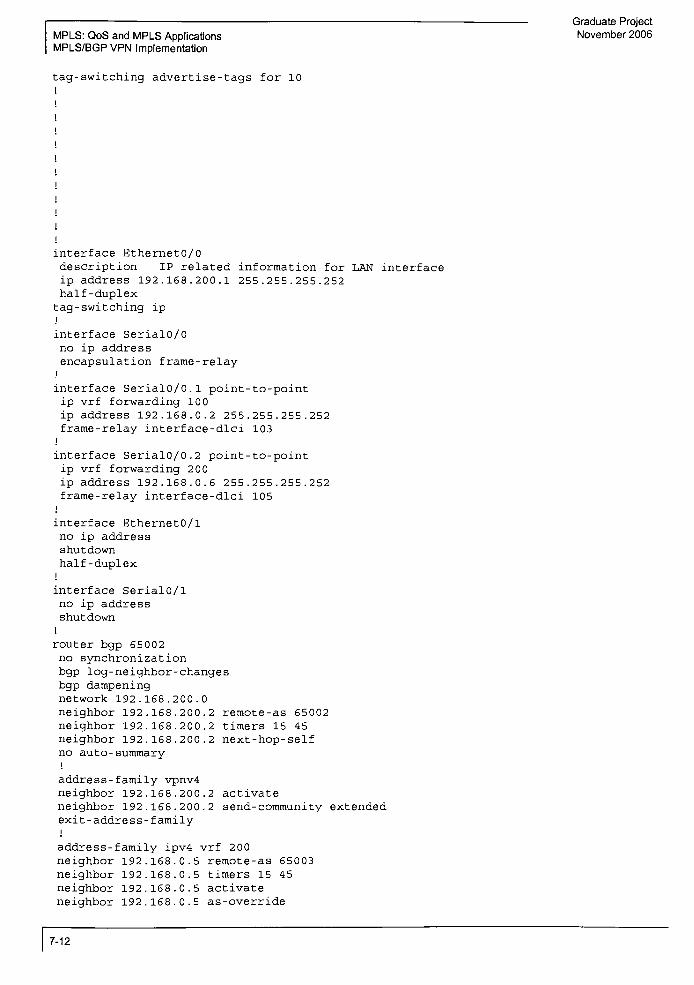
Graduate Project
MPLS: QoS and MPLS Applications November 2006
MPLS/BGP VPN Implementation
tag-switching advertise-tags for 10
interface EthernetO/0
description IP related information for LAN interface
ip address 192.168.200.1 255.255.255.252
half -duplex
tag-switching ip
i
interface Serial0/0
no ip address
encapsulation frame-relayi
interface Serial0/0.1 point-to-point
ip vrf forwarding 100
ip address 192.168.0.2 255.255.255.252
frame-relay interface-dlci 103
i
interface SerialO/0.2 point-to-point
ip vrf forwarding 200
ip address 192.168.0.6 255.255.255.252
frame-relay interface-dlci 105
I
interface Ethernet0/1
no ip address
shutdown
half -duplex
i
interface Serial0/1
no ip address
shutdown
j
router bgp 65002
no synchronization
bgp log -neighbor-changes
bgp dampeningnetwork 192.168.200.0
neighbor 192.168.200.2 remote-as 65002
neighbor 192.168.200.2 timers 15 45
neighbor 192.168.200.2 next-hop-self
no auto-
summaryi
address -family vpnv4
neighbor 192.168.200.2 activate
neighbor 192.168.200.2 send-community extended
exit -address -family
i
address-family ipv4 vrf 200
neighbor 192.168.0.5 remote-as 65003
neighbor 192.168.0.5 timers 15 45
neighbor 192.168.0.5 activate
neighbor 192.168.0.5 as-override
7-12

Graduate Project
November 2006
no auto-
summary
no synchronization
exit -address -family
;
address-
family ipv4 vrf 100
neighbor 192.168.0.1 remote-as 65001
neighbor 192.168.0.1
neighbor 192.168.0.1
neighbor 192.168.0.1
noauto-
summary
no synchronization
exit -address -family
i
ip http server
ip classless
MPLS: QoS and MPLS Applications
MPLS/BGP VPN Implementation
timers 15 45
activate
as -override
access-list 10 permit 192.168.0.0 0.0.0.255
i
control -plane
line con
line aux
line vty
end
ISP-PE1#
ISP-PEl#show ip bgp summary
BGP router identifier 192.169.200.1, local AS number 65002
BGP table version is 2, main routing table version 2
1 network entries using 117 bytes of memory
1 path entries using 52 bytes of memory
8/1 BGP path/bestpath attribute entries using 992 bytes of memory
2 BGP AS-PATH entries using 48 bytes of memory
2 BGP extended community entries using 48 bytes of memory
0 BGP route-map cache entries using 0 bytes of memory
0 BGP filter-list cache entries using 0 bytes of memory
BGP using 1257 total bytes of memory
Dampening enabled. 0 history paths, 0 dampened paths
BGP activity 6/1 prefixes, 6/1 paths, scan interval 60 sees
V AS MsgRcvd MsgSent
4 65002 326 322
Neighbor
192.168.200.2
ISP-PE1#
ISP-PE1#
ISP-PE1#
ISP-PE1#
ISP-PEl#show ip bgp vpnv4 all
TblVer InQ OutQ Up/Down State/PfxRcd
2 0 0 01:16:46 1
7-13

Graduate Project
MPLS: QoS and MPLS Applications November 2006
MPLS/BGP VPN Implementation
BGP table version is 12, local router ID is 192.169.200.1
Status codes: s suppressed, d damped, h history, *valid, > best, i internal,
r RIB-failure, S Stale
Origin codes: i IGP, e EGP, ? incomplete
Network Next Hop Metric LocPrf Weight Path
Route Distinguisher: 65002:100 (default for vrf 100)
*> 10.100.100.0/24 192.168.0.1 0 0 65001 i
*>il0. 100. 200. 0/24 192.168.200.2 0 100 0 65001 i
Route Distinguisher: 65002:200 (default for vrf 200)
*> 10.100.100.0/24 192.168.0.5 0 0 65003 i
*>il0. 100. 200. 0/24 192.168.200.2 0 100 0 65003 i
ISP-PE1#
ISP-PE1#
ISP-PE1#
ISP-PE1#
ISP-PE1#
ISP-PE1#
ISP-PEl#show ip bgp vpnv4 vrf 100 summary
BGP router identifier 192.169.200.1, local AS number 65002
BGP table version is 12, main routing table version 12
2 network entries using 274 bytes of memory
2 path entries using 136 bytes of memory
8/4 BGP path/bestpath attribute entries using 992 bytes of memory
2 BGP AS-PATH entries using 48 bytes of memory
2 BGP extended community entries using 4 8 bytes of memory
0 BGP route-map cache entries using 0 bytes of memory
0 BGP filter-list cache entries using 0 bytes of memory
BGP using 1498 total bytes of memory
BGP activity 6/1 prefixes, 6/1 paths, scan interval 15 sees
Neighbor V AS MsgRcvd MsgSent TblVer InQ OutQ Up/Down State/PfxRcd
192.168.0.1 4 65001 329 329 12 0 0 01:21:05 1
ISP-PE1#
ISP-PE1#
ISP-PE1#
ISP-PE1#
ISP-PEl#show ip bgp vpnv4 vrf 200 summary
BGP router identifier 192.169.200.1, local AS number 65002
BGP table version is 12, main routing table version 12
2 network entries using 274 bytes of memory
2 path entries using 136 bytes of memory
8/4 BGP path/bestpath attribute entries using 992 bytes of memory
2 BGP AS-PATH entries using 48 bytes of memory
2 BGP extended community entries using 48 bytes of memory
0 BGP route-map cache entries using 0 bytes of memory
0 BGP filter-list cache entries using 0 bytes of memory
BGP using 1498 total bytes of memory
BGP activity 6/1 prefixes, 6/1 paths, scan interval 15 sees
Neighbor V AS MsgRcvd MsgSent TblVer InQ OutQ Up/Down State/PfxRcd
192.168.0.5 4 65003 156 156 12 0 0 00:37:53 1
ISP-PE1#
ISP-PE1#
ISP-PE1#
ISP-PE1#
ISP-PEl#show ip bgp vpnv4 vrf 100 neighbor 192.168.0.1 rou
BGP table version is 12, local router ID is 192.169.200.1
Status codes: s suppressed, d damped, h history, *valid, > best, i internal,
r RIB-failure, S Stale
Origin codes: i IGP, e EGP, ? incomplete
7-14

Graduate Project .
November 2006MpLS: QoS and MpLS App|icatjons
MPLS/BGP VPN Implementation
Network Next Hop Metric LocPrf Weight Path
Route Distinguisher: 65002:100 (default for vrf 100)
*> 10.100.100.0/24 192.168.0.1 0 0 65001 i
Total number of prefixes 1
ISP-PE1#
ISP-PEl#show ip bgp vpnv4 vrf 100 neighbor 192.168.0.1 adve
ISP-PEl#show ip bgp vpnv4 vrf 100 neighbor 192.168.0.1 advertised-routes
BGP table version is 12, local router ID is 192.169.200.1
Status codes: s suppressed, d damped, h history, *valid, > best, i internal,
r RIB-failure, S Stale
Origin codes: i IGP, e EGP, ? incomplete
Network Next Hop Metric LocPrf Weight Path
Route Distinguisher: 65002:100 (default for vrf 100)
*>il0. 100. 200. 0/24 192.168.200.2 0 100 0 65001 i
Total number of prefixes 1
ISP-PE1#
ISP-PE1#
ISP-PE1#
ISP-PEl#show ip bgp vpnv4 vrf 200 neighbor 192.168.0.13 rou
% No such neighbor or address familyISP-PEl#show ip bgp vpnv4 vrf 200 neighbor 192.168.0.5 rou
BGP table version is 12, local router ID is 192.169.200.1
Status codes: s suppressed, d damped, h history, kvalid, > best, i internal,
r RIB-failure, S Stale
Origin codes: i IGP, e EGP, ? incomplete
Network Next Hop Metric LocPrf Weight Path
Route Distinguisher: 65002:200 (default for vrf 200)
*> 10.100.100.0/24 192.168.0.5 0 0 65003 i
Total number of prefixes 1
ISP-PE1#
ISP-PE1#
ISP-PEl#show ip bgp vpnv4 vrf 200 neighbor 192.168.0.5 adver
ISP-PEl#show ip bgp vpnv4 vrf 200 neighbor 192.168.0.5 advertised-routes
BGP table version is 12, local router ID is 192.169.200.1
Status codes: s suppressed, d damped, h history, *valid, > best, i internal,
r RIB-failure, S Stale
Origin codes: i IGP, e EGP, ? incomplete
Network Next Hop Metric LocPrf Weight Path
Route Distinguisher: 65002:200 (default for vrf 200)
*>il0. 100. 200. 0/24 192.168.200.2 0 100 0 65003 i
Total number of prefixes 1
ISP-PE1#
ISP-PE1#
ISP-PE1#
ISP-PEl#show ip bgp vpnv4 rd 65002:100
BGP table version is 12, local router ID is 192.169.200.1
Status codes: s suppressed, d damped, h history, *valid, > best, i internal,
r RIB-failure, S Stale
Origin codes: i IGP, e EGP, ? incomplete
Network Next Hop Metric LocPrf Weight Path
Route Distinguisher: 65002:100 (default for vrf 100)
*> 10.100.100.0/24 192.168.0.1 0 0 65001 i
*>il0. 100. 200. 0/24 192.168.200.2 0 100 0 65001 i
ISP-PE1#
7-15
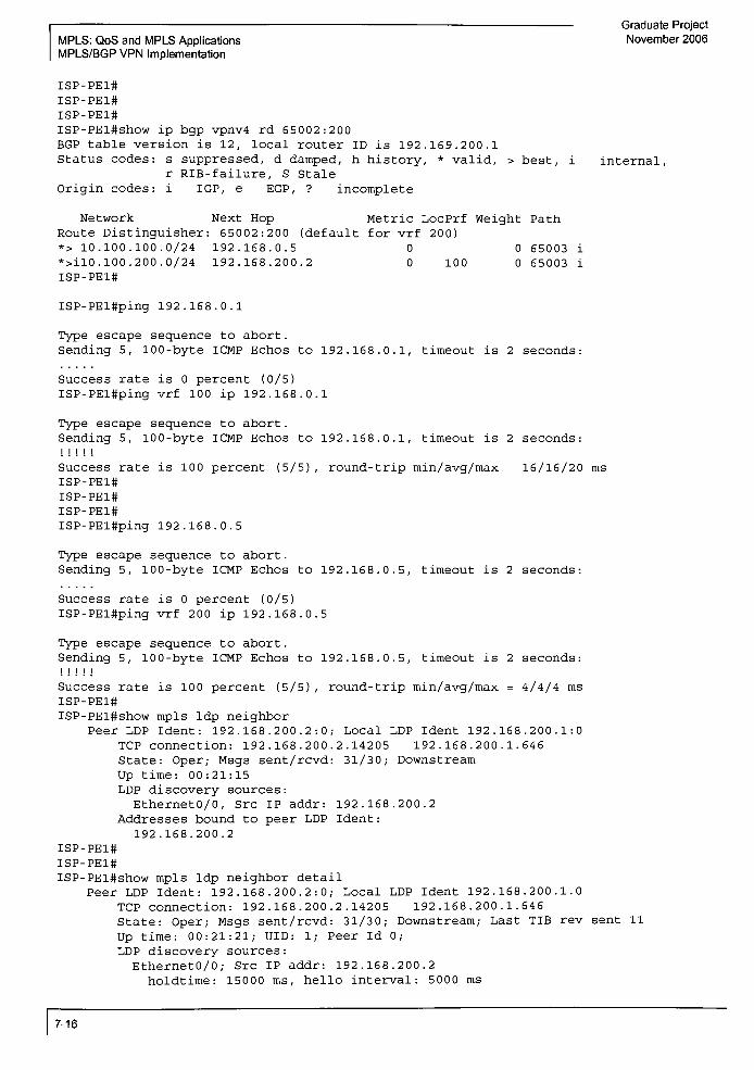
Graduate Project
MPLS: QoS and MPLS Applications November 2006
MPLS/BGP VPN Implementation
ISP-PE1#
ISP-PE1#
ISP-PE1#
ISP-PEl#show ip bgp vpnv4 rd 65002:200
BGP table version is 12, local router ID is 192.169.200.1
Status codes: s suppressed, d damped, h history, *valid, > best, i internal,
r RIB-failure, S Stale
Origin codes: i IGP, e EGP, ? incomplete
Network Next Hop Metric LocPrf Weight Path
Route Distinguisher: 65002:200 (default for vrf 200)
*> 10.100.100.0/24 192.168.0.5 0 0 65003 i
*>il0. 100. 200. 0/24 192.168.200.2 0 100 0 65003 i
ISP-PE1#
ISP-PEl#ping 192.168.0.1
Type escape sequence to abort .
Sending 5, 100-byte ICMP Echos to 192.168.0.1, timeout is 2 seconds:
Success rate is 0 percent (0/5)
ISP-PEl#ping vrf 100 ip 192.168.0.1
Type escape sequence to abort .
Sending 5, 100-byte ICMP Echos to 192.168.0.1, timeout is 2 seconds:
I i i j j
Success rate is 100 percent (5/5) , round-trip min/avg/max 16/16/20 ms
ISP-PE1#
ISP-PE1#
ISP-PE1#
ISP-PEl#ping 192.168.0.5
Type escape sequence to abort .
Sending 5, 100-byte ICMP Echos to 192.168.0.5, timeout is 2 seconds:
Success rate is 0 percent (0/5)
ISP-PEl#ping vrf 200 ip 192.168.0.5
Type escape sequence to abort .
Sending 5, 100-byte ICMP Echos to 192.168.0.5, timeout is 2 seconds:
Mill
Success rate is 100 percent (5/5), round-trip min/avg/max = 4/4/4 ms
ISP-PE1#
ISP-PEl#show mpls ldp neighbor
Peer LDP Ident : 192.168.200.2:0; Local LDP Ident 192.168.200.1:0
TCP connection: 192.168.200.2.14205 192.168.200.1.646
State: Oper; Msgs sent/rcvd: 31/30; Downstream
Up time: 00:21:15
LDP discovery sources:
EthernetO/0, Src IP addr: 192.168.200.2
Addresses bound to peer LDP Ident:
192.168.200.2
ISP-PE1#
ISP-PE1#
ISP-PEl#show mpls ldp neighbor detail
Peer LDP Ident: 192.168.200.2:0; Local LDP Ident 192.168.200.1:0
TCP connection: 192.168.200.2.14205 192.168.200.1.646
State: Oper; Msgs sent/rcvd: 31/30; Downstream; Last TIB rev sent 11
Up time: 00:21:21; UID: 1; Peer Id 0;
LDP discovery sources:
EthernetO/0; Src IP addr: 192.168.200.2
holdtime: 15000 ms, hello interval: 5000 ms
7-16

Graduate Project
November 2006MPLS: QoS and MPLS Applications
MPLS/BGP VPN Implementation
Addresses bound to peer LDP Ident:
192.168.200.2
Peer holdtime: 180000 ms; KA interval: 60000 ms ; Peer state: estab
ISP-PE1#
ISP-PEl#show ip route vrf 100
Routing Table: 10 0
Codes: C connected, S static, R RIP, M mobile, B BGP
D EIGRP, EX EIGRP external, 0 OSPF, IA OSPF inter area
Nl OSPF NSSA external type 1, N2 OSPF NSSA external type 2
El OSPF external type 1, E2 OSPF external type 2
i IS-IS, su IS-IS summary, Ll IS-IS level-1, L2 IS-IS level-2
ia IS-IS inter area,*
candidate default, U per-user static route
o ODR, P periodic downloaded static route
Gateway of last resort is not set
10.0.0.0/24 is subnetted, 2 subnets
B 10.100.100.0 [20/0] via 192.168.0.1, 01:20:12
B 10.100.200.0 [200/0] via 192.168.200.2, 01:43:43
192.168.0.0/30 is subnetted, 1 subnets
C 192.168.0.0 is directly connected, Serial0/0.1
ISP-PE1#
ISP-PE1#
ISP-PEl#show ip route vrf 200
Routing Table: 200
Codes: C connected, S static, R RIP, M mobile, B BGP
D EIGRP, EX EIGRP external, 0 OSPF, IA OSPF inter area
Nl OSPF NSSA external type 1, N2 OSPF NSSA external type 2
El OSPF external type 1, E2 OSPF external type 2
i IS-IS, su IS-IS summary, Ll IS-IS level-1, L2 IS-IS level-2
ia IS-IS inter area,* candidate default, U per-user static route
o ODR, P periodic downloaded static route
Gateway of last resort is not set
10.0.0.0/24 is subnetted, 2 subnets
B 10.100.100.0 [20/0] via 192.168.0.5, 01:32:32
B 10.100.200.0 [200/0] via 192.168.200.2, 01:28:47
192.168.0.0/30 is subnetted, 1 subnets
C 192.168.0.4 is directly connected, SerialO/0.2
ISP-PE1#
ISP-PEl#show ip route
Codes: C connected, S static, R RIP, M mobile, B BGP
D EIGRP, EX EIGRP external, 0 OSPF, IA OSPF inter area
Nl OSPF NSSA external type 1, N2 OSPF NSSA external type 2
El OSPF external type 1, E2 OSPF external type 2
i IS-IS, su IS-IS summary, Ll IS-IS level-1, L2 IS-IS level-2
ia IS-IS inter area,* candidate default, U per-user static route
o ODR, P periodic downloaded static route
Gateway of last resort is not set
192.168.200.0/24 is variably subnetted, 2 subnets, 2 masks
C 192.168.200.0/30 is directly connected, EthernetO/0
B 192.168.200.0/24 [200/0] via 192.168.200.2, 02:12:31
ISP-PE1#
Router Configuration for ISP-PE2:
7-17

Graduate Project
MPLS: QoS and MPLS Applications November 2006
MPLS/BGP VPN Implementation
ISP-PE2>en
ISP-PE2#
ISP-PE2#
ISP-PE2#show run
Building configuration. . .
Current configuration 2278 bytesi
version 12.3
service timestamps debug datetime msec
service timestamps log datetime msec
no service password-encryption
;
hostname ISP-PE2
i
boot -
start -marker
boot -end-marker
i
i
no aaa new-model
i
resource policyi
memory-size iomem 10
ip subnet -zero
!
i
ip cef
no ip dhcp use vrf connected
i
i
ip vrf 10 0
description Customer A
rd 65002:100
route-target export 6500:100
route-target import 6500:100
i
ip vrf 200
description Customer B
rd 65002:200
route -target export 65002:200
route-target import 65002:200
mpls label protocol ldpno tag-switching advertise-tags
tag-switching advertise-tags for 10
interface EthernetO/0
description IP related information for LAN interface
ip address 192.168.200.2 255.255.255.0
7-18

Graduate Project
November 2006 MPLS: QoS and MPLS Applications
MPLS/BGP VPN Implementation
half-duplex
tag-switching ip;
interface Serial0/0
no ip address
encapsulation frame-relayno fair-queue
i
interface Serial0/0.1 point-to-point
ip vrf forwarding 10 0
ip address 192.168.0.14 255.255.255.252
frame-relay interface-dlci 204
;
interface Serial0/0.2 point-to-point
ip vrf forwarding 2 00
ip address 192.168.0.18 255.255.255.252
frame-relay interface-dlci 209
i
interface Ethernet0/1
no ip address
shutdown
half -duplex
!
interface Serial0/l
no ip address
shutdown
l
router bgp 65 002
bgp log -neighbor-changes
neighbor 192.168.0.17 remote-as 65003
neighbor 192.168.0.17 timers 15 45
neighbor 192.168.200.1 remote-as 65002
neighbor 192.168.200.1 timers 15 45
i
address-family ipv4
neighbor 192.168.0.17 activate
neighbor 192.168.200.1 activate
neighbor 192.168.200.1 next-hop-self
no auto-
summary
no synchronization
bgp dampeningnetwork 192.168.200.0
exit -address -family
address-family vpnv4
neighbor 192.168.200.
neighbor 192.168.200.
exit -address -family
1 activate
1 send-community extended
address-family ipv4 vrf 200
neighbor 192.168.0.17 remote-as 65003
neighbor 192.168.0.17 timers 15 45
neighbor 192.168.0.17 activate
neighbor 192.168.0.17 as-override
no auto-
summary
no synchronization
exit -address-familyi
address-family ipv4 vrf 100
neighbor 192.168.0.13 remote-as 65001
neighbor 192.168.0.13 timers 15 45
neighbor 192.168.0.13 activate
7-19
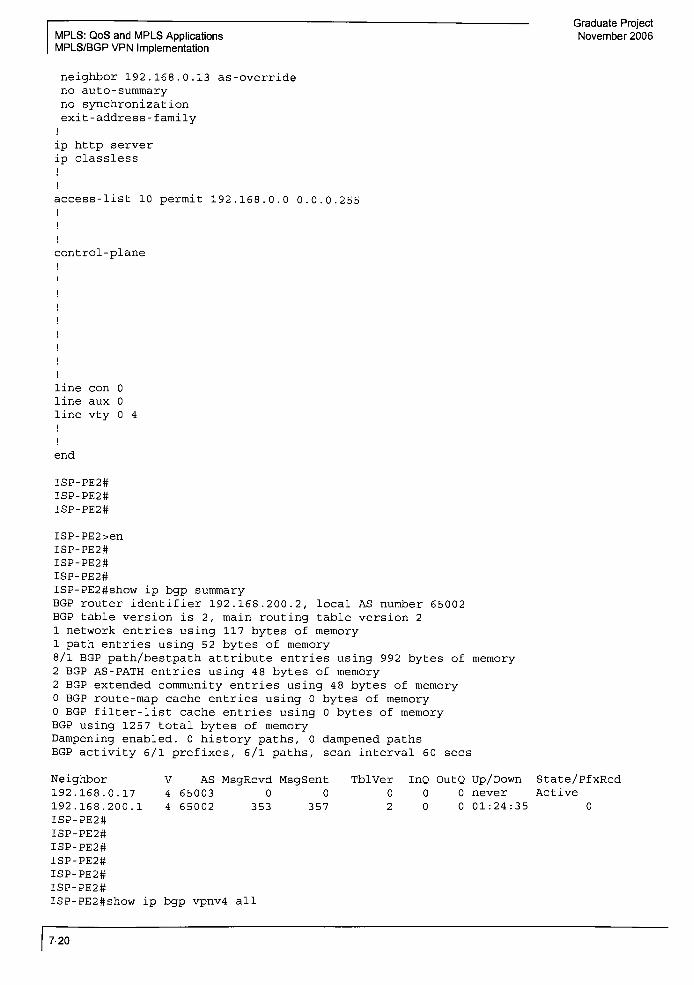
Graduate Project
MPLS: QoS and MPLS Applications November 2006
MPLS/BGP VPN Implementation
neighbor 192.168.0.13 as-override
noauto-
summary
no synchronization
exit-address-
familyi
ip http server
ip classless
j
I
access-list 10 permit 192.168.0.0 0.0.0.255
j
j
I
control -plane
i
i
I
|
line con 0
line aux 0
line vty 0 4
i
i
end
ISP-PE2#
ISP-PE2#
ISP-PE2#
ISP-PE2>en
ISP-PE2#
ISP-PE2#
ISP-PE2#
ISP-PE2#show ip bgp summary
BGP router identifier 192.168.200.2, local AS number 65002
BGP table version is 2, main routing table version 2
1 network entries using 117 bytes of memory
1 path entries using 52 bytes of memory
8/1 BGP path/bestpath attribute entries using 992 bytes of memory
2 BGP AS-PATH entries using 48 bytes of memory
2 BGP extended community entries using 4 8 bytes of memory
0 BGP route-map cache entries using 0 bytes of memory
0 BGP filter-list cache entries using 0 bytes of memory
BGP using 1257 total bytes of memory
Dampening enabled. 0 history paths, 0 dampened paths
BGP activity 6/1 prefixes, 6/1 paths, scan interval 60 sees
Neighbor
192.168.0.17
192.168.200.1
ISP-PE2#
ISP-PE2#
ISP-PE2#
ISP-PE2#
ISP-PE2#
ISP-PE2#
ISP-PE2#show ip bgp vpnv4 all
7-20
V AS MsgRcvd MsgSent TblVer InQ OutQ Up/Down State/PfxRcd
4 65003 0 0 0 0 0 never Active
4 65002 353 357 2 0 0 01:24:35 0

Graduate Project
November 2006MPLS: QoS and MPLS App|icat|ons
MPLS/BGP VPN Implementation
BGP table version is 12, local router ID is 192.168.200.2
Status codes: s suppressed, d damped, h history, *valid, > best, i internal,
r RIB-failure, S Stale
Origin codes: i IGP, e EGP, ? incomplete
Network Next Hop Metric LocPrf Weight Path
Route Distinguisher: 65002:100 (default for vrf 100)
*>il0. 100. 100. 0/24 192.168.200.1 0 100 0 65001 i
*> 10.100.200.0/24 192.168.0.13 0 0 65001 i
Route Distinguisher: 65002:200 (default for vrf 200)
*>il0 .100 .100 .0/24 192.168.200.1 0 100 0 65003 i
*> 10.100.200.0/24 192.168.0.17 0 0 65003 i
ISP-PE2#
ISP-PE2#
ISP-PE2#
ISP-PE2#
ISP-PE2#show ip bgp vpn vrf 100 summary
BGP router identifier 192.168.200.2, local AS number 65002
BGP table version is 12, main routing table version 12
2 network entries using 274 bytes of memory
2 path entries using 13 6 bytes of memory
8/4 BGP path/bestpath attribute entries using 992 bytes of memory
2 BGP AS-PATH entries using 48 bytes of memory
2 BGP extended community entries using 48 bytes of memory
0 BGP route-map cache entries using 0 bytes of memory
0 BGP filter-list cache entries using 0 bytes of memory
BGP using 1498 total bytes of memory
BGP activity 6/1 prefixes, 6/1 paths, scan interval 15 sees
Neighbor V AS MsgRcvd MsgSent TblVer InQ OutQ Up/Down State/PfxRcd
192.168.0.13 4 65001 358 358 12 0 0 01:28:16 1
ISP-PE2#
ISP-PE2#
ISP-PE2#
ISP-PE2#
ISP-PE2#
ISP-PE2#show ip bgp vpn vrf 200 summary
BGP router identifier 192.168.200.2, local AS number 65002
BGP table version is 12, main routing table version 12
2 network entries using 274 bytes of memory
2 path entries using 136 bytes of memory
8/4 BGP path/bestpath attribute entries using 992 bytes of memory
2 BGP AS-PATH entries using 48 bytes of memory
2 BGP extended community entries using 4 8 bytes of memory
0 BGP route-map cache entries using 0 bytes of memory
0 BGP filter-list cache entries using 0 bytes of memory
BGP using 1498 total bytes of memory
BGP activity 6/1 prefixes, 6/1 paths, scan interval 15 sees
Neighbor V AS MsgRcvd MsgSent TblVer InQ OutQ Up/Down State/PfxRcd
192.168.0.17 4 65003 173 173 12 0 0 00:42:04 1
ISP-PE2#
ISP-PE2#
ISP-PE2#show ip bgp vpn vrf 100 nei 192.168.0.13 ro
BGP table version is 12, local router ID is 192.168.200.2
Status codes: s suppressed, d damped, h history, *valid, > best, i internal,
r RIB-failure, S Stale
Origin codes: i IGP, e EGP, ? incomplete
Network Next Hop Metric LocPrf Weight Path
Route Distinguisher: 65002:100 (default for vrf 100)
*> 10.100.200.0/24 192.168.0.13 0 0 65001 i
7-21

MPLS: QoS and MPLS Applications
MPLS/BGP VPN Implementation
Graduate Project
November 2006
Total number of prefixes 1
ISP-PE2#show ip bgp vpn vrf 100 nei 192.168.0.13 ad
BGP table version is 12, local router ID is 192.168.200.2
Status codes: s suppressed, d damped, h history, *valid, > best, i internal,
r RIB-failure, S Stale
Origin codes: i IGP, e EGP, ? incomplete
Network Next Hop Metric LocPrf Weight Path
Route Distinguisher: 65002:100 (default for vrf 100)
*>il0. 100. 100. 0/24 192.168.200.1 0 100 0 65001 i
Total number of prefixes 1
ISP-PE2#
ISP-PE2#
ISP-PE2#
ISP-PE2#show ip bgp vpn vrf 200 nei 192.168.0.17 rou
BGP table version is 12, local router ID is 192.168.200.2
Status codes: s suppressed, d damped, h history, *valid, > best, i
r RIB-failure, S Stale
Origin codes: i IGP, e EGP, ? incomplete
Network Next Hop Metric LocPrf Weight Path
Route Distinguisher: 65002:200 (default for vrf 200)
*> 10.100.200.0/24 192.168.0.17 0 0 65003 i
internal,
Total number of prefixes 1
ISP-PE2#
ISP-PE2#
ISP-PE2#show ip bgp vpn vrf 200 nei 192.168.0.17 adv
BGP table version is 12, local router ID is 192.168.200.2
Status codes: s suppressed, d damped, h history, *valid, > best, i internal,
r RIB-failure, S Stale
Origin codes: i IGP, e EGP, ? incomplete
Network Next Hop Metric LocPrf Weight Path
Route Distinguisher: 65002:200 (default for vrf 200)
*>il0. 100. 100. 0/24 192.168.200.1 0 100 0 65003 i
Total number of prefixes 1
ISP-PE2#
ISP-PE2#
ISP-PE2#
ISP-PE2#show ip bgp vpnv4 rd 65002:100
BGP table version is 12, local router ID is 192.168.200.2
Status codes: s suppressed, d damped, h history, *valid, > best,
r RIB-failure, S Stale
Origin codes: i IGP, e EGP, ? incomplete
Network Next Hop Metric LocPrf Weight Path
Route Distinguisher: 65002:100 (default for vrf 100)
internal ,
192.168.200.1
192.168.0.13
*>il0. 100. 100. 0/24
*> 10.100.200.0/24
ISP-PE2#
ISP-PE2#
ISP-PE2#
ISP-PE2#show ip bgp vpnv4 rd 65002:200
BGP table version is 12, local router ID is 192.
Status codes: s suppressed, d damped, h history,
r RIB-failure, S Stale
Origin codes: i IGP, e EGP, ? incomplete
100 65001
65001
168.200.2
*valid, > best, i internal,
7-22

Graduate Project
November 2006MPLS: QoS and MpLS Applications
MPLS/BGP VPN Implementation
Network Next Hop Metric LocPrf Weight Path
Route Distinguisher: 65002:200 (default for vrf 200)
*>il0. 100. 100. 0/24 192.168.200.1 0 100 0 65003 i
*> 10.100.200.0/24 192.168.0.17 0 0 65003 i
ISP-PE2#
ISP-PE2#
ISP-PE2#
ISP-PE2#
ISP-PE2#show mpls ldp nei
Peer LDP Ident: 192.168.200.1:0; Local LDP Ident 192.168.200.2:0
TCP connection: 192.168.200.1.646 192.168.200.2.14205
State: Oper; Msgs sent/rcvd: 31/32; Downstream
Up time: 00:21:56
LDP discovery sources:
EthernetO/0, Src IP addr: 192.168.200.1
Addresses bound to peer LDP Ident:
192.168.200.1
ISP-PE2#
ISP-PE2#
ISP-PE2#
ISP-PE2#show mpls ldp nei det
Peer LDP Ident: 192.168.200.1:0; Local LDP Ident 192.168.200.2:0
TCP connection: 192.168.200.1.646 192.168.200.2.14205
State: Oper; Msgs sent/rcvd: 31/32; Downstream; Last TIB rev sent 7
Up time: 00:22:06; UID: 1; Peer Id 0 ;
LDP discovery sources:
EthernetO/0; Src IP addr: 192.168.200.1
holdtime: 15000 ms, hello interval. 5000 ms
Addresses bound to peer LDP Ident:
192 .168 .200.1
Peer holdtime: 180000 ms; KA interval: 60000 ms ; Peer state: estab
ISP-PE2#
ISP-PE2#show ip route vrf 100
Routing Table: 10 0
Codes: C connected, S static, R RIP, M mobile, B BGP
D EIGRP, EX EIGRP external, 0 OSPF, IA OSPF inter area
Nl OSPF NSSA external type 1, N2 OSPF NSSA external type 2
El OSPF external type 1, E2 OSPF external type 2
i IS-IS, su IS-IS summary, Ll IS-IS level-1, L2 IS-IS level-2
ia IS-IS inter area,* candidate default, U per-user static route
o ODR, P periodic downloaded static route
Gateway of last resort is not set
10.0.0.0/24 is subnetted, 2 subnets
B 10.100.100.0 [200/0] via 192.168.200.1, 01:19:11
B 10.100.200.0 [20/0] via 192.168.0.13, 01:45:58
192.168.0.0/30 is subnetted, 1 subnets
C 192.168.0.12 is directly connected, Serial0/0.1
ISP-PE2#
ISP-PE2#
ISP-PE2#
ISP-PE2#show ip route vrf 200
Routing Table: 200
Codes: C connected, S static, R RIP, M mobile, B BGP
D EIGRP, EX EIGRP external, 0 OSPF, IA OSPF inter area
Nl OSPF NSSA external type 1, N2 OSPF NSSA external type 2
El OSPF external type 1, E2 OSPF external type 2
i IS-IS, su IS-IS summary, Ll IS-IS level-1, L2 IS-IS level-2
ia IS-IS inter area,* candidate default, U per-user static route
7-23

Graduate Project
MPLS: QoS and MPLS Applications November 2006
MPLS/BGP VPN Implementation
o ODR, P periodic downloaded static route
Gateway of last resort is not set
10.0.0.0/24 is subnetted, 2 subnets
B 10.100.100.0 [200/0] via 192.168.200.1, 01:31:45
B 10.100.200.0 [20/0] via 192.168.0.17, 01:28:15
192.168.0.0/30 is subnetted, 1 subnets
C 192.168.0.16 is directly connected, Serial0/0.2
ISP-PE2#
ISP-PE2#
ISP-PE2#
ISP-PE2#
ISP-PE2#show ip route
Codes: C connected, S static, R RIP, M mobile, B BGP
D EIGRP, EX EIGRP external, O OSPF, IA OSPF inter area
Nl OSPF NSSA external type 1, N2 OSPF NSSA external type 2
El OSPF external type 1, E2 OSPF external type 2
i IS-IS, su IS-IS summary, Ll IS-IS level-1, L2 IS-IS level-2
ia IS-IS inter area,* candidate default, U per-user static route
o ODR, P periodic downloaded static route
Gateway of last resort is not set
C 192.168.200.0/24 is directly connected, EthernetO/0
7-24

Graduate Project
November 2006MPLS: QoS and MPLS Applications
References
8 References/Bibliography
Books
[1] Black, Uyless D. (2001). MPLS andLabel Switching Networks. Upper Saddly River, New Jersey:
Prentice Hall PTR.
[2] Gallaher, Rick. (2003 ) . Rick Gallaher 's MPLS Training Guide: BuildingMulti Protocol Label
SwitchingNetworks . Rockland, MA: Syngress Publicing, Inc.
[3] Lewis, Mark. (2006). Comparing, Designing, andDeploying VPNs. Indianapolis, IN: Cisco Press.
[4] Bruce, Davie, & Rekhter, Yakov (2000). MPLS: Technology andApplications. San Francisco, CA:Morgan Kaufmann Publishers.
Request For Comments
[5] RFC 1633, Integrated Services in the InternetArchitecture: an Overview. R. Braden, D. Clark, andS. Shenker. June 1994.
[6] RFC 2475, An Architecturefor Differentiated Services. S. Blake, D. Black, M. Carlson, E. Davies,Z. Wang, andW. Weiss. December 1998.
[7] RFC 3270,Multi-Protocol Label Switching (MPLS) Support ofDifferentiated Services. F. Le
Faucheur, L. Wu, B. Davie, S. Davari, P. Vaananen, R. Krishnan, P. Cheval, and J. Heinanen.
May 2002.
[8] RFC 1349, Type ofService in the Internet Protocol Suite. P. Almquist. July 1992.
[9] RFC 2474, Definition oftheDifferentiated Services Field (DSField) in the IPv4 and IPv6Headers.K. Nichols, S. Blake, F. Baker, and D. Black. December 1998.
[10] RFC 2702, Requirements ofTraffic Engineering OverMPLS. D. Awduche, J. Malcolm, J.
Agogbua, M. O'Dell, and J. McManus. September 1999.
[1 1] RFC 303 1, Multiprotocol Label SwitchingArchitecture. E. Rosen, A. Viswanathan, and R. Collan.
January 200 1 .
[12] RFC 3034, Use ofLabel Switching on Frame Relay Networks Specification. A. Conta, P. Doolan,and A. Malis. January 2001.
[13] RFC 3209, RSVP-TE: Extensions to RSVPforLSP Tunnels. D. Awduche, L. Berger, T. Li, V.
Srinivasan, and G. Swallow. December 200 1 .
[14] RFC 4420, Encoding ofAttributesforMultiprotocol Label Switching (MPLS) Label SwitchedPath
(LSP) Establishment UsingResource Reservation Protocol-Traffic Engineering (RSVP-TE). A.
Farrel, D. Papadimitriou, J.-P. Vasseur, and A. Ayyanger. February 2006.
[15] RFC 4364, BGP/MPLS IP VirtualPrivate Networks (VPNs). E. Rosen, and Y. Rekhter. February2006.
White Papers
[16] Chuck Semeria. SupportingDifferentiated Service Classes:Multiprotocol Label Switching (MPLS).
Sunnyvale, CA. Juniper Networks, Inc. White Paper, August 2002: 200039-001 .
[17] InaMinei.MPLSDiffServ-aware Traffic Engineering. Sunnyvale, CA. Juniper Networks, Inc.
White Paper: 200048-001.
[18] RFC 3209
[19] Layer 2 VirtualPrivate Networks (L2VPN). World Wide Packets. White Paper, December 2005.
[20] TimWu.MPLS VPNs: Layer 2 orLayer 3? Understanding the Choice. River Stone Networks.
White Paper: #128.
[21] Paul Brittain & Adrian Farrel. MPLS Virtual Private Networks. Data Connection Limited, Enfield,
UK. White Paper, November 2000.
8-1

Graduate Project
MPLS: QoS and MPLS Applications November 2006
References
[22] Chuck Semeria.Multiprotocol Label Switching: EnhancingRouting in the New Public Network.
JuniperNetworks,Mountain View, CA. White Paper, September 27, 1999: 200001-002.
WebMaterials
[23] Web ProForum Tutorials. (2006). A Comparison ofMultiprotocol Label Switching (MPLS)Traffic-
Engineering Initiatives. Retrieved March 13, 2006, from
http://www.iec.org/online/tutorials/acrobat/mpls traffic.pdf
[24] The MFA SUPERDemo. (2004).MPLSReady to Serve The Enterprise: Supercomm Chicago 2004
Public Interoperability Event. RetrievedMarch 13, 2006, from
http://www.mfaforum.org/tech/superdemo_2004.pdf
[25] Cisco Systems White Paper. Cisco IOS MPLS Quality of Service. Retrieved March 13, 2006,
from http://www.cisco.com/warp/public/cc/pd/iosw/prodlit/mpios_wp.htm
[26] Payer, Udo. (2005). DiffServ, IntServ, MPLS. Retrieved July 5, 2006, from
http://vvv^vy.iaik.tugraz.at/teaching/03_advanced%20computer%20networks/ss2005/vo2/DiffSe
rv%20IntServ%20MPLS.pdf
[27] Dreilinger, Timea. DiffServ andMPLS. Retrieved July 27, 2006, from
http://saturn.acad.bg/bis/pdfs/04_doklad.pdf
[28] Welcher, Dr. Pete. (2003). Condensed QoSforMPLS. Retrieved June 4, 2006, from
http://www.netcraftsmen.net/welcher/seminars/mpls-qos.pdf
[29] Sachdev, Avneesh. (2003). Implementation ofQoSMechanisms inMPLS networks. Retrieved June
4, 2006, from http://www.mpls.ip/2003/presentations/QoS 2.pdf
[30] Linhares, Rodrigo. IP QoSArchitectureHighlighting a Direction. Retrieved June 10, 2006, from
http://www.rnp.br/_arquivo/sci/2000/qos-ip.pdf
[31] Paresh Shah, Utpal Mukhopadhyaya, and Arun Sathiamuthi. (2006). Overview ofQoS in Packet-
based IP andMPLSNetworks. Retrieved June 4, 2006, fromhttp://www.nanog.org/mtg-
0602/pdf/sathiamurthi.pdf
[32] Website, TheMPLSResource Center, www.mplsrc.com/standards.shtml
8-2