Multi-Process CNC Build Preliminary Proposal · Multi-Process CNC Build Preliminary Proposal ......
20
Multi-Process CNC Build Preliminary Proposal Bader Alfadhli Jessica Collins Sara Hamadah Uday Kadhum Micael Ljungberg Jason Troxler 2016-17 Project Sponsor: NAU/CEFNS Faculty Advisor: David Willy Sponsor Mentor: David Willy Instructor: Dr. Trevas
Transcript of Multi-Process CNC Build Preliminary Proposal · Multi-Process CNC Build Preliminary Proposal ......

Multi-Process CNC Build
Preliminary Proposal
Bader Alfadhli
Jessica Collins
Sara Hamadah
Uday Kadhum
Micael Ljungberg
Jason Troxler
2016-17
Project Sponsor: NAU/CEFNS
Faculty Advisor: David Willy
Sponsor Mentor: David Willy
Instructor: Dr. Trevas

ii
DISCLAIMER
This report was prepared by students as part of a university course requirement. While considerable effort
has been put into the project, it is not the work of licensed engineers and has not undergone the extensive
verification that is common in the profession. The information, data, conclusions, and content of this
report should not be relied on or utilized without thorough, independent testing and verification.
University faculty members may have been associated with this project as advisors, sponsors, or course
instructors, but as such they are not responsible for the accuracy of results or conclusions.
iii
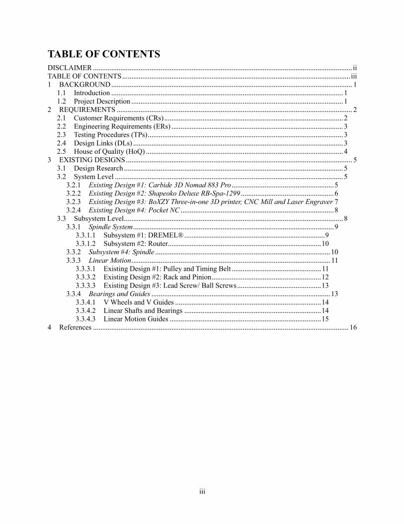
TABLE OF CONTENTS
DISCLAIMER .............................................................................................................................................. ii TABLE OF CONTENTS ............................................................................................................................. iii 1 BACKGROUND .................................................................................................................................... 1
1.1 Introduction ............................................................................................................................... 1 1.2 Project Description .................................................................................................................... 1
2 REQUIREMENTS ................................................................................................................................. 2 2.1 Customer Requirements (CRs) .................................................................................................. 2 2.2 Engineering Requirements (ERs) .............................................................................................. 3 2.3 Testing Procedures (TPs) ........................................................................................................... 3 2.4 Design Links (DLs) ................................................................................................................... 3 2.5 House of Quality (HoQ) ............................................................................................................ 4
3 EXISTING DESIGNS ............................................................................................................................ 5 3.1 Design Research ........................................................................................................................ 5 3.2 System Level ............................................................................................................................. 5
3.2.1 Existing Design #1: Carbide 3D Nomad 883 Pro ........................................................ 5 3.2.2 Existing Design #2: Shapeoko Deluxe RB-Spa-1299 ................................................... 6 3.2.3 Existing Design #3: BoXZY Three-in-one 3D printer, CNC Mill and Laser Engraver 7 3.2.4 Existing Design #4: Pocket NC .................................................................................... 8
3.3 Subsystem Level ........................................................................................................................ 8 3.3.1 Spindle System .............................................................................................................. 9
3.3.1.1 Subsystem #1: DREMEL® ............................................................................. 9 3.3.1.2 Subsystem #2: Router.................................................................................... 10
3.3.2 Subsystem #4: Spindle ................................................................................................ 10 3.3.3 Linear Motion ............................................................................................................. 11
3.3.3.1 Existing Design #1: Pulley and Timing Belt ................................................. 11 3.3.3.2 Existing Design #2: Rack and Pinion ............................................................ 12 3.3.3.3 Existing Design #3: Lead Screw/ Ball Screws .............................................. 13
3.3.4 Bearings and Guides .................................................................................................. 13 3.3.4.1 V Wheels and V Guides ................................................................................ 14 3.3.4.2 Linear Shafts and Bearings ........................................................................... 14 3.3.4.3 Linear Motion Guides ................................................................................... 15
4 References ............................................................................................................................................ 16
1
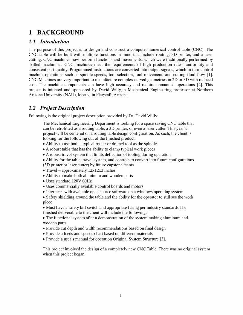
1 BACKGROUND
1.1 Introduction
The purpose of this project is to design and construct a computer numerical control table (CNC). The
CNC table will be built with multiple functions in mind that include routing, 3D printer, and a laser
cutting. CNC machines now perform functions and movements, which were traditionally performed by
skilled machinists. CNC machines meet the requirements of high production rates, uniformity and
consistent part quality. Programmed instructions are converted into output signals, which in turn control
machine operations such as spindle speeds, tool selection, tool movement, and cutting fluid flow [1].
CNC Machines are very important to manufacture complex curved geometries in 2D or 3D with reduced
cost. The machine components can have high accuracy and require unmanned operations [2]. This
project is initiated and sponsored by David Willy, a Mechanical Engineering professor at Northern
Arizona University (NAU), located in Flagstaff, Arizona.
1.2 Project Description
Following is the original project description provided by Dr. David Willy:
The Mechanical Engineering Department is looking for a space saving CNC table that
can be retrofitted as a routing table, a 3D printer, or even a laser cutter. This year’s
project will be centered on a routing table design configuration. As such, the client is
looking for the following out of the finished product:
Ability to use both a typical router or dremel tool as the spindle
A robust table that has the ability to clamp typical work pieces
A robust travel system that limits deflection of tooling during operation
Ability for the table, travel system, and controls to convert into future configurations
(3D printer or laser cutter) by future capstone teams
Travel – approximately 12x12x3 inches
Ability to make both aluminum and wooden parts
Uses standard 120V 60Hz
Uses commercially available control boards and motors
Interfaces with available open source software on a windows operating system
Safety shielding around the table and the ability for the operator to still see the work
piece
Must have a safety kill switch and appropriate fusing per industry standards The
finished deliverable to the client will include the following:
The functional system after a demonstration of the system making aluminum and
wooden parts
Provide cut depth and width recommendations based on final design
Provide a feeds and speeds chart based on different materials
Provide a user’s manual for operation Original System Structure [3].
This project involved the design of a completely new CNC Table. There was no original system
when this project began.
2
2 REQUIREMENTS
This section explains the different parts of the House of Quality, including customer requirements,
engineering requirements, testing procedure, and design links.
2.1 Customer Requirements (CRs)
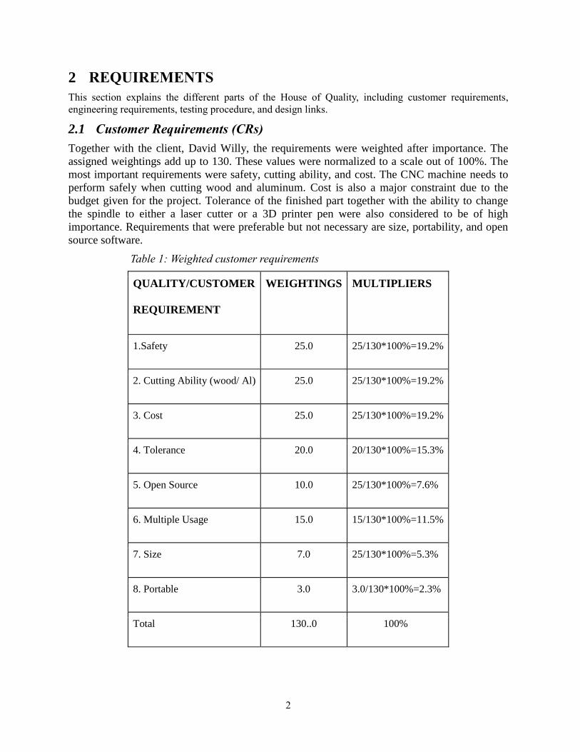
Together with the client, David Willy, the requirements were weighted after importance. The
assigned weightings add up to 130. These values were normalized to a scale out of 100%. The
most important requirements were safety, cutting ability, and cost. The CNC machine needs to
perform safely when cutting wood and aluminum. Cost is also a major constraint due to the
budget given for the project. Tolerance of the finished part together with the ability to change
the spindle to either a laser cutter or a 3D printer pen were also considered to be of high
importance. Requirements that were preferable but not necessary are size, portability, and open
source software.
Table 1: Weighted customer requirements
QUALITY/CUSTOMER
REQUIREMENT
WEIGHTINGS MULTIPLIERS
1.Safety 25.0 25/130*100%=19.2%
2. Cutting Ability (wood/ Al) 25.0 25/130*100%=19.2%
3. Cost 25.0 25/130*100%=19.2%
4. Tolerance 20.0 20/130*100%=15.3%
5. Open Source 10.0 25/130*100%=7.6%
6. Multiple Usage 15.0 15/130*100%=11.5%
7. Size 7.0 25/130*100%=5.3%
8. Portable 3.0 3.0/130*100%=2.3%
Total 130..0 100%
3
2.2 Engineering Requirements (ERs)
[Use this section to list and discuss the Engineering Requirements that
have been developed. ER’s must be verifiable, that is, specify
objectively measurable parameters or conditions. Each ER must have a
target, or design-to, value with tolerance along with
justification/rationale for the selected value and tolerance]
2.3 Testing Procedures (TPs)
This section will be updated in later reports.
2.4 Design Links (DLs)
This section will be updated in later reports.
4
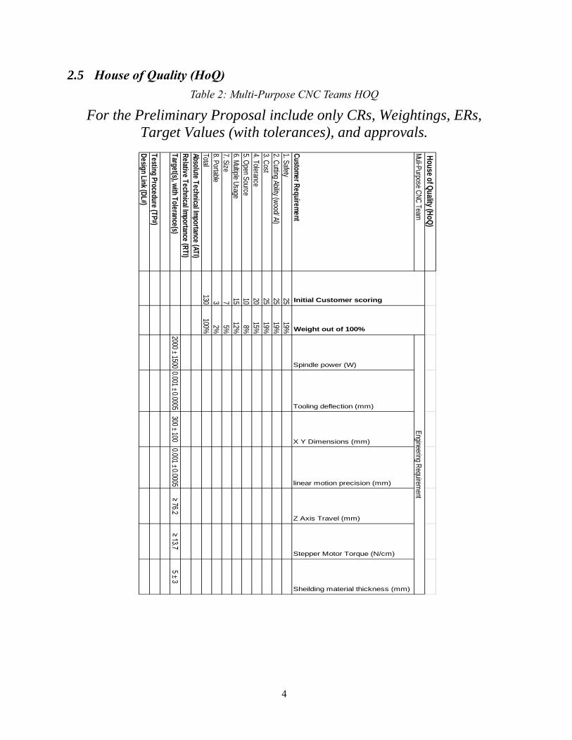
2.5 House of Quality (HoQ)
Table 2: Multi-Purpose CNC Teams HOQ
For the Preliminary Proposal include only CRs, Weightings, ERs,
Target Values (with tolerances), and approvals.
Ho
use o
f Qu
ality (Ho
Q)
Muli-P
urpose CN
C Team
Custom
er Requirem
ent
Spindle power (W)
Tooling deflection (mm)
X Y Dimensions (mm)
linear motion precision (mm)
Z Axis Travel (mm)
Stepper Motor Torque (N/cm)
Sheilding material thickness (mm)
1. Safety
2519%
2. Cutting Ability (w
ood/ Al)25
19%
3. Cost
2519%
4. Tolerance20
15%
5. Open S
ource10
8%
6. Multiple U
sage15
12%
7. Size
75%
8. Portable
32%
Total130
100%
Absolute Technical Im
portance (ATI)
Relative T
echnical Importance (R
TI)
Target(s), w
ith Tolerance(s)
2000 ± 15000.001 ± 0.0005
300 ± 1000.001 ± 0.0005
≥ 76.2≥ 13.7
5 ± 3
Testing P
rocedure (TP
#)
Design Link (D
L#)
Engineering R
equirement
Weight out of 100%
Initial Customer scoring
5
3 EXISTING DESIGNS
CNC machines come in different sizes and models depending on the application. The following section
explains how the team started researching over a wide range of CNC machines and similar machines.
The section also includes different alternatives of CNC machines as well as different alternatives for the
subsystems of a CNC machine.
3.1 Design Research
The purpose of the research was to expand on the team’s previous knowledge of CNC machines, and
widen the knowledge about machines used for similar applications. The research incorporated CNC
machines as well as lathes, drill presses, and milling machines. The research also included machines
ranging from machines used in industry to machines used for hobby applications. Web-based sources
comprised most of the research because of both the diversity, as well as the amount of information.
Without previous knowledge of building a CNC router table, the team conducted extensive research
about the CNC router table and its components.
3.2 System Level
This section examines commercially available CNC machines. The following designs assisted in
generating ideas for meeting the client’s needs. Each table uses a router or similar cutting instrument and
can mill multiple materials from wax, various plastics, hardwoods and metals. The tables are compared
based on cutting area, power, software available, size and cost. Cutting area, power, software, and size
are project requirements. Cost is used a benchmarking tool for comparing various capabilities between
the different machines.
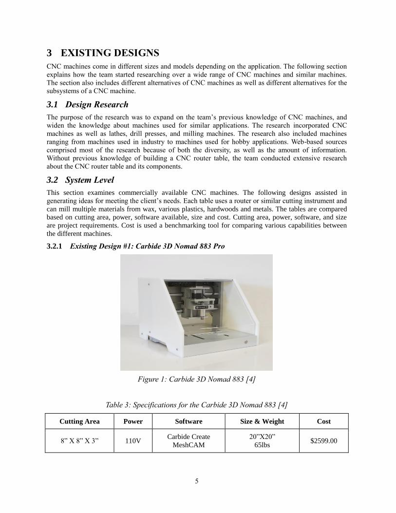
3.2.1 Existing Design #1: Carbide 3D Nomad 883 Pro
Figure 1: Carbide 3D Nomad 883 [4]
Table 3: Specifications for the Carbide 3D Nomad 883 [4]
Cutting Area Power Software Size & Weight Cost
8” X 8” X 3” 110V Carbide Create
MeshCAM 20”X20”
65lbs $2599.00

6
The Nomad 883 Pro is a fully enclosed desktop CNC machine capable of cutting all materials and is
Mac and Windows compatible. This design is comprised mainly of aluminum and comes in HDPE
(High-Density Polyethylene) or Bamboo housing.
Design #1 is fully enclosed which protects users and bystanders from expelled pieces of milled
materials. This project requires a safety shield to ensure expelled milled materials do not harm
bystanders. This design shows an option of adding a safety shield to the table without compromising the
machine’s capabilities and allows for viewability.
3.2.2 Existing Design #2: Shapeoko Deluxe RB-Spa-1299
Figure 2: Shapeoko Deluxe RB-Spa-1299 [5]
Table 4: Specifications for the Shapeoko Deluxe RB-Spa-1299 [5]
Cutting Area Power Software Size & Weight Cost
17” X17” X 3” 24V Open Source Java 28.5” X 23.6”
55lbs $999.95
The Shapeoko is a desktop 3-axis milling CNC machine capable of milling non-ferrous metals such as
aluminum, hardwoods and plastics. This table is comprised of steel and extruded aluminum, spindle head
is not included in this package.
Design #2 is not enclosed but offers a larger cutting surface closer to those required. Another of this
project’s requirements is that the table is capable of using some type of open source software, which this
table is capable of.
7
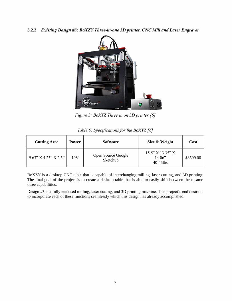
3.2.3 Existing Design #3: BoXZY Three-in-one 3D printer, CNC Mill and Laser Engraver
Figure 3: BoXYZ Three in on 3D printer [6]
Table 5: Specifications for the BoXYZ [6]
Cutting Area Power Software Size & Weight Cost
9.63” X 4.25” X 2.5” 19V Open Source Google
Sketchup
15.5” X 13.35” X
14.06” 40-45lbs
$3599.00
BoXZY is a desktop CNC table that is capable of interchanging milling, laser cutting, and 3D printing.
The final goal of the project is to create a desktop table that is able to easily shift between these same
three capabilities.
Design #3 is a fully enclosed milling, laser cutting, and 3D printing machine. This project’s end desire is
to incorporate each of these functions seamlessly which this design has already accomplished.
8
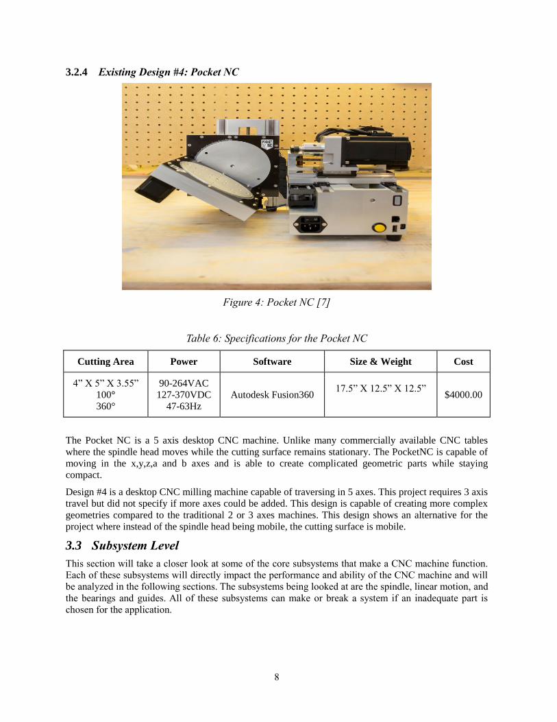
3.2.4 Existing Design #4: Pocket NC
Figure 4: Pocket NC [7]
Table 6: Specifications for the Pocket NC
Cutting Area Power Software Size & Weight Cost
4” X 5” X 3.55” 100° 360°
90-264VAC 127-370VDC
47-63Hz Autodesk Fusion360
17.5” X 12.5” X 12.5”
$4000.00
The Pocket NC is a 5 axis desktop CNC machine. Unlike many commercially available CNC tables
where the spindle head moves while the cutting surface remains stationary. The PocketNC is capable of
moving in the x,y,z,a and b axes and is able to create complicated geometric parts while staying
compact.
Design #4 is a desktop CNC milling machine capable of traversing in 5 axes. This project requires 3 axis
travel but did not specify if more axes could be added. This design is capable of creating more complex
geometries compared to the traditional 2 or 3 axes machines. This design shows an alternative for the
project where instead of the spindle head being mobile, the cutting surface is mobile.
3.3 Subsystem Level
This section will take a closer look at some of the core subsystems that make a CNC machine function.
Each of these subsystems will directly impact the performance and ability of the CNC machine and will
be analyzed in the following sections. The subsystems being looked at are the spindle, linear motion, and
the bearings and guides. All of these subsystems can make or break a system if an inadequate part is
chosen for the application.
9
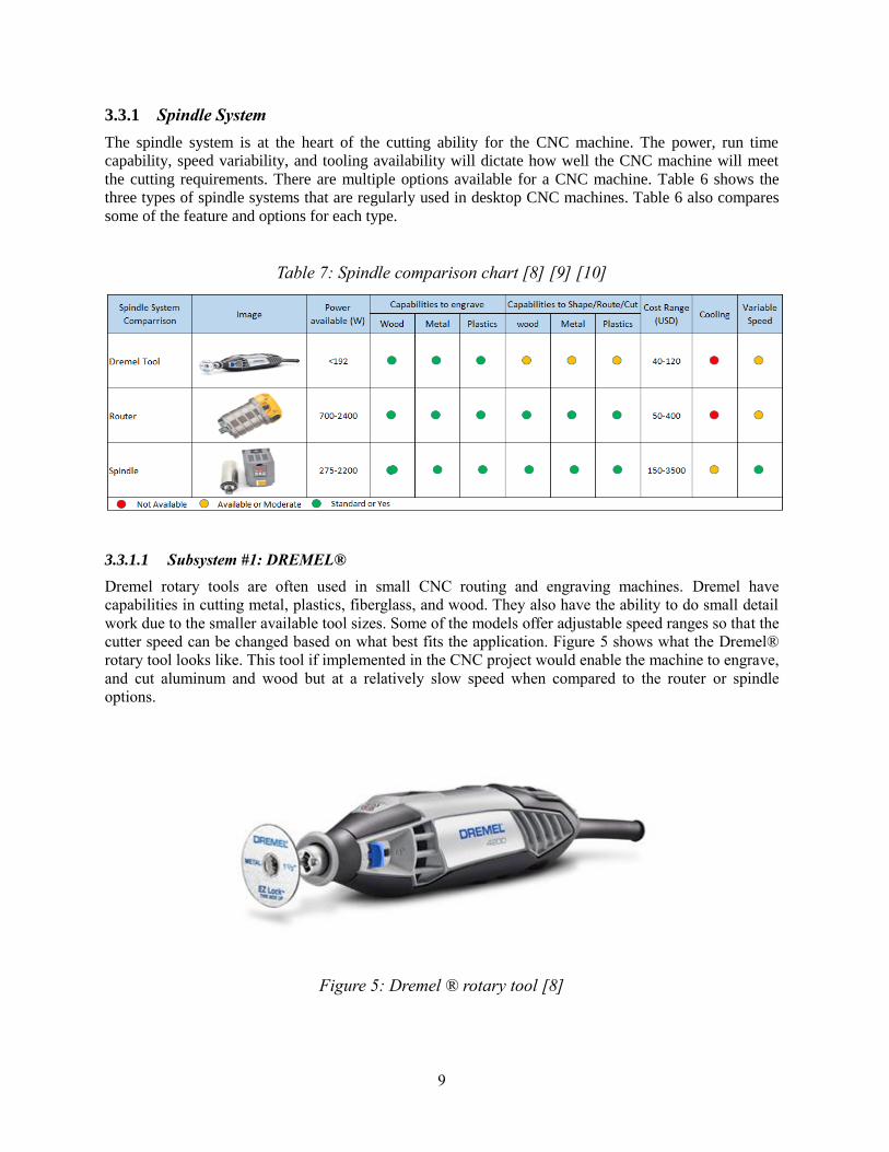
3.3.1 Spindle System
The spindle system is at the heart of the cutting ability for the CNC machine. The power, run time
capability, speed variability, and tooling availability will dictate how well the CNC machine will meet
the cutting requirements. There are multiple options available for a CNC machine. Table 6 shows the
three types of spindle systems that are regularly used in desktop CNC machines. Table 6 also compares
some of the feature and options for each type.
Table 7: Spindle comparison chart [8] [9] [10]
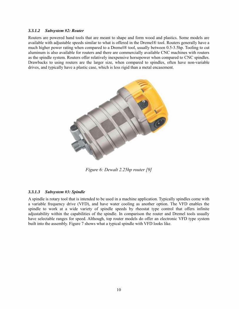
3.3.1.1 Subsystem #1: DREMEL®
Dremel rotary tools are often used in small CNC routing and engraving machines. Dremel have
capabilities in cutting metal, plastics, fiberglass, and wood. They also have the ability to do small detail
work due to the smaller available tool sizes. Some of the models offer adjustable speed ranges so that the
cutter speed can be changed based on what best fits the application. Figure 5 shows what the Dremel®
rotary tool looks like. This tool if implemented in the CNC project would enable the machine to engrave,
and cut aluminum and wood but at a relatively slow speed when compared to the router or spindle
options.
Figure 5: Dremel ® rotary tool [8]
10
3.3.1.2 Subsystem #2: Router
Routers are powered hand tools that are meant to shape and form wood and plastics. Some models are
available with adjustable speeds similar to what is offered in the Dremel® tool. Routers generally have a
much higher power rating when compared to a Dremel® tool, usually between 0.5-3.5hp. Tooling to cut
aluminum is also available for routers and there are commercially available CNC machines with routers
as the spindle system. Routers offer relatively inexpensive horsepower when compared to CNC spindles.
Drawbacks to using routers are the larger size, when compared to spindles, often have non-variable
drives, and typically have a plastic case, which is less rigid than a metal encasement.
Figure 6: Dewalt 2.25hp router [9]
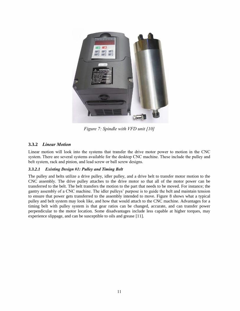
3.3.1.3 Subsystem #3: Spindle
A spindle is rotary tool that is intended to be used in a machine application. Typically spindles come with
a variable frequency drive (VFD), and have water cooling as another option. The VFD enables the
spindle to work at a wide variety of spindle speeds by rheostat type control that offers infinite
adjustability within the capabilities of the spindle. In comparison the router and Dremel tools usually
have selectable ranges for speed. Although, top router models do offer an electronic VFD type system
built into the assembly. Figure 7 shows what a typical spindle with VFD looks like.
11
Figure 7: Spindle with VFD unit [10]
3.3.2 Linear Motion
Linear motion will look into the systems that transfer the drive motor power to motion in the CNC
system. There are several systems available for the desktop CNC machine. These include the pulley and
belt system, rack and pinion, and lead screw or ball screw designs.
3.3.2.1 Existing Design #1: Pulley and Timing Belt
The pulley and belts utilize a drive pulley, idler pulley, and a drive belt to transfer motor motion to the
CNC assembly. The drive pulley attaches to the drive motor so that all of the motor power can be
transferred to the belt. The belt transfers the motion to the part that needs to be moved. For instance; the
gantry assembly of a CNC machine. The idler pulleys’ purpose is to guide the belt and maintain tension
to ensure that power gets transferred to the assembly intended to move. Figure 8 shows what a typical
pulley and belt system may look like, and how that would attach to the CNC machine. Advantages for a
timing belt with pulley system is that gear ratios can be changed, accurate, and can transfer power
perpendicular to the motor location. Some disadvantages include less capable at higher torques, may
experience slippage, and can be susceptible to oils and grease [11].

12
Figure 8: Timing belt and pulley arrangement [12]
3.3.2.2 Existing Design #2: Rack and Pinion
Rack and pinion drive systems use a pinion gear and a drive rack. The pinion gear is either connected
directly or indirectly, with a belt, to a drive motor. When the drive motor turns, it drives the pinion gear
on the rack. This moves the pinion assembly along the rack, or depending on how it is positioned, the
rack across the pinion gear. Figure 9 shows a rack and pinion with a belt driven pinion gear, this is an
example of a stationary rack with moving pinion gear.
Figure 9:Stationary rack and belt driven pinion assembly [13]

13
3.3.2.3 Existing Design #3: Lead Screw/ Ball Screws
Lead screws and ball screws use a spirally machined shaft to drive parts back and forth. A typical
lead/ball screw assembly will consist of two fixed bearings, screw shaft, and a drive housing. The fixed
bearings will support the assembly on either end so that the shaft can freely rotate without translating.
The screw shaft can be driven at one end by either attaching a belt, pulley, or directly by a drive motor.
The drive housing is where the lead screw and balls screw assemblies differ. Lead screw drive housings
have a matching thread pattern to the screw shaft. This enables the drive housing to translate when the
screw shaft rotates. The ball screw drive housing contains a system of recirculating balls that move
around within the drive housing when the screw shaft is turned, reducing the friction when compared to
the lead screw system. Advantage to the lead/ball screw systems is that they can be very precise,
accurate, and handle heavy loads. Disadvantages are that they can be expensive when compared to other
drive systems and the ball screws can be driven backwards without a braking system [14]. A
recirculating ball drive assembly is shown on a screw shaft in Figure 10.
Figure 10: Recirculating ball drive assembly with screw shaft [15]
3.3.3 Bearings and Guides
Bearings and guides are important to the efficiency and accuracy of the CNC system. Just as the drive
system previously discussed, the bearings and guides have a large impact on the accuracy and
repeatability of movement. A poorly designed bearing and guide system will result in twisting of
assemblies or unwanted lateral translation.
14
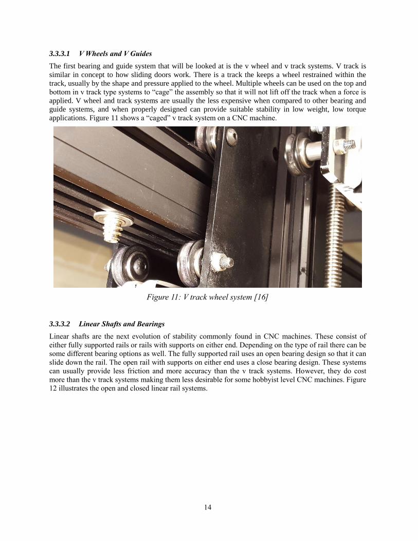
3.3.3.1 V Wheels and V Guides
The first bearing and guide system that will be looked at is the v wheel and v track systems. V track is
similar in concept to how sliding doors work. There is a track the keeps a wheel restrained within the
track, usually by the shape and pressure applied to the wheel. Multiple wheels can be used on the top and
bottom in v track type systems to “cage” the assembly so that it will not lift off the track when a force is
applied. V wheel and track systems are usually the less expensive when compared to other bearing and
guide systems, and when properly designed can provide suitable stability in low weight, low torque
applications. Figure 11 shows a “caged” v track system on a CNC machine.
Figure 11: V track wheel system [16]
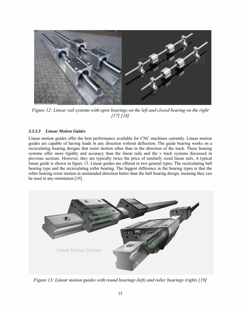
3.3.3.2 Linear Shafts and Bearings
Linear shafts are the next evolution of stability commonly found in CNC machines. These consist of
either fully supported rails or rails with supports on either end. Depending on the type of rail there can be
some different bearing options as well. The fully supported rail uses an open bearing design so that it can
slide down the rail. The open rail with supports on either end uses a close bearing design. These systems
can usually provide less friction and more accuracy than the v track systems. However, they do cost
more than the v track systems making them less desirable for some hobbyist level CNC machines. Figure
12 illustrates the open and closed linear rail systems.
15
Figure 12: Linear rail systems with open bearings on the left and closed bearing on the right
[17] [18]
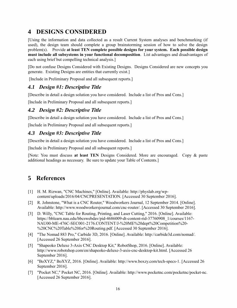
3.3.3.3 Linear Motion Guides
Linear motion guides offer the best performance available for CNC machines currently. Linear motion
guides are capable of having loads in any direction without deflection. The guide bearing works on a
recirculating bearing designs that resist motion other than in the direction of the track. These bearing
systems offer more rigidity and accuracy than the linear rails and the v track systems discussed in
previous sections. However, they are typically twice the price of similarly sized linear rails. A typical
linear guide is shown in figure 13. Linear guides are offered in two general types. The recirculating ball
bearing type and the recirculating roller bearing. The biggest difference in the bearing types is that the
roller bearing resist motion in unintended direction better than the ball bearing design, meaning they can
be used in any orientation [19].
Figure 13: Linear motion guides with round bearings (left) and roller bearings (right) [19]
16
4 DESIGNS CONSIDERED
[Using the information and data collected as a result Current System analyses and benchmarking (if
used), the design team should complete a group brainstorming session of how to solve the design
problem(s). Provide at least TEN complete possible designs for your system. Each possible design
must include all subsystems in your functional decomposition. List advantages and disadvantages of
each using brief but compelling technical analysis.]
[Do not confuse Designs Considered with Existing Designs. Designs Considered are new concepts you
generate. Existing Designs are entities that currently exist.]
[Include in Preliminary Proposal and all subsequent reports.]
4.1 Design #1: Descriptive Title
[Describe in detail a design solution you have considered. Include a list of Pros and Cons.]
[Include in Preliminary Proposal and all subsequent reports.]
4.2 Design #2: Descriptive Title
[Describe in detail a design solution you have considered. Include a list of Pros and Cons.]
[Include in Preliminary Proposal and all subsequent reports.]
4.3 Design #3: Descriptive Title
[Describe in detail a design solution you have considered. Include a list of Pros and Cons.]
[Include in Preliminary Proposal and all subsequent reports.]
[Note: You must discuss at least TEN Designs Considered. More are encouraged. Copy & paste
additional headings as necessary. Be sure to update your Table of Contents.]
5 References
[1] H. M. Rizwan, "CNC Machines," [Online]. Available: http://physlab.org/wp-
content/uploads/2016/04/CNCPRESENTATION. [Accessed 30 September 2016].
[2] R. Johnstone, "What is a CNC Router," Woodworkers Journal, 12 September 2014. [Online].
Available: http://www.woodworkersjournal.com/cnc-router/. [Accessed 30 September 2016].
[3] D. Willy, "CNC Table for Routing, Printing, and Laser Cutting," 2016. [Online]. Available:
https://bblearn.nau.edu/bbcswebdav/pid-4686009-dt-content-rid-37760908_1/courses/1167-
NAU00-ME-476C-SEC001-2176.CONTENT/J-%20ME%20dept%20Competition%20-
%20CNC%20Table%20for%20Routing.pdf. [Accessed 30 September 2016].
[4] "The Nomad 883 Pro," Carbide 3D, 2016. [Online]. Available: http://carbide3d.com/nomad/.
[Accessed 26 September 2016].
[5] "Shapeoko Deluxe 3-Axis CNC Desktop Kit," RobotShop, 2016. [Online]. Available:
http://www.robotshop.com/en/shapeoko-deluxe-3-axis-cnc-desktop-kit.html. [Accessed 26
September 2016].
[6] "BoXYZ," BoXYZ, 2016. [Online]. Available: http://www.boxzy.com/tech-specs-1. [Accessed 26
September 2016].
[7] "Pocket NC," Pocket NC, 2016. [Online]. Available: http://www.pocketnc.com/pocketnc/pocket-nc.
[Accessed 26 September 2016].

17
[8] "4200 High-Performance Rotary Tool," DREMEL, 2016. [Online]. Available:
https://www.dremel.com/en_US/products/-/show-product/tools/4200-high-performance-rotary-
tool#.V-bB3CgrKUl. [Accessed 24 September 2016].
[9] "DEWALT 2-1/4 HP Elctronic Variable Speed Router with Soft Start," The Home Depot, 2016.
[Online]. Available: http://www.homedepot.com/p/DEWALT-2-1-4-HP-Electronic-Variable-Speed-
Router-Motor-with-Soft-Start-
DW618M/203164064?cm_mmc=SEM%7CTHD%7Cgoogle%7C&mid=sbDUziBU7%7Cdc_mtid_
8903tb925190_pcrid_50250225699_pkw__pmt__product_203164064_slid_&gclid=COWQgufjqM
8CFcEd. [Accessed 24 September 2016].
[10] technical.jrs, "2.2KW Water Cooled Spindle Motor ER20& VFD Inverter Drive 80mm Diamter
CNC," ebay, 19 August 2016. [Online]. Available: http://www.ebay.com/itm/2-2KW-WATER-
COOLED-SPINDLE-MOTOR-ER20-VFD-INVERTER-DRIVE-80MM-DIAMETER-CNC-
/252029788256. [Accessed 24 September 2016].
[11] "Timing Belt Advantages and Disadvantages," Ecreativeworks, 2016. [Online]. Available:
http://www.pfeiferindustries.com/timing-belt-advantages-disadvantages-i-15-l-en.html. [Accessed
24 September 2016].
[12] J. Saunders, "DIY Cheap Arduino CNC Machine - Machine is Complete and Accurate!," Weebly, 5
January 2015. [Online]. Available: http://www.nyccnc.com/wednesday-widget/diy-cheap-arduino-
cnc-machine-machine-is-complete-and-accurate. [Accessed 24 September 2016].
[13] "Standard Rand and Pinion Drive, NEMA 23," CNCRouterParts, 2016. [Online]. Available:
http://www.cncrouterparts.com/standard-rack-and-pinion-drive-nema-23-p-
50.html?osCsid=3g4t8fu77c7bonr6vck89ej3v1. [Accessed 24 September 2016].
[14] "The Engineer's Guide: Lead Screws VS. Ball Screws," 2016. [Online]. Available:
http://www.engr.uvic.ca/~mech464/lead_screw_vs_ball_screw.pdf. [Accessed 24 September 2016].
[15] "Our Ball Screw repair process," American Ball and Screw, 2016. [Online]. Available:
http://www.americanballscrewrepair.com/ball-screw-repair-process/. [Accessed 24 September
2016].
[16] MattWheeler, "A 30 minute x-axis mod to reduce chatter," Inventables, 2 November 2015. [Online].
Available: https://discuss.inventables.com/t/a-30-minute-x-axis-mod-to-reduce-chatter/15775.
[Accessed 24 September 2016].
[17] econvenience1986, "2 Set SBR20-1500mm 20mm Fully Supported Linear Rail Shaft Rod with 4
SBR20UU," ebay, 4 August 2016. [Online]. Available: http://www.ebay.com/itm/2-Set-SBR20-
1500mm-20-MM-FULLY-SUPPORTED-LINEAR-RAIL-SHAFT-ROD-with-4-SBR20UU-
/251022549100. [Accessed 24 September 2016].
[18] mhestore2009, "2Pcs 8mm 400mm Linear Shaft Rod Rail Kit W/ Bearing Block for 3D Printer
CNC," ebay, 26 September 2016. [Online]. Available: http://www.ebay.com/itm/2Pcs-8mm-
400mm-Linear-Shaft-Rod-Rail-Kit-W-Bearing-Block-For-3D-Printer-CNC-/371697485067.
[Accessed 26 September 2016].
[19] "Linear Motion Guides," DC Auto-Motion, 2016. [Online]. Available: http://www.dcauto-
motion.co.za/thk/linear-motion-guides/. [Accessed 24 September 2016].