MULTI-PLATE - Armtec · armtec.com – drainage solutions since 1908 multi-plate versatile bridge...
20
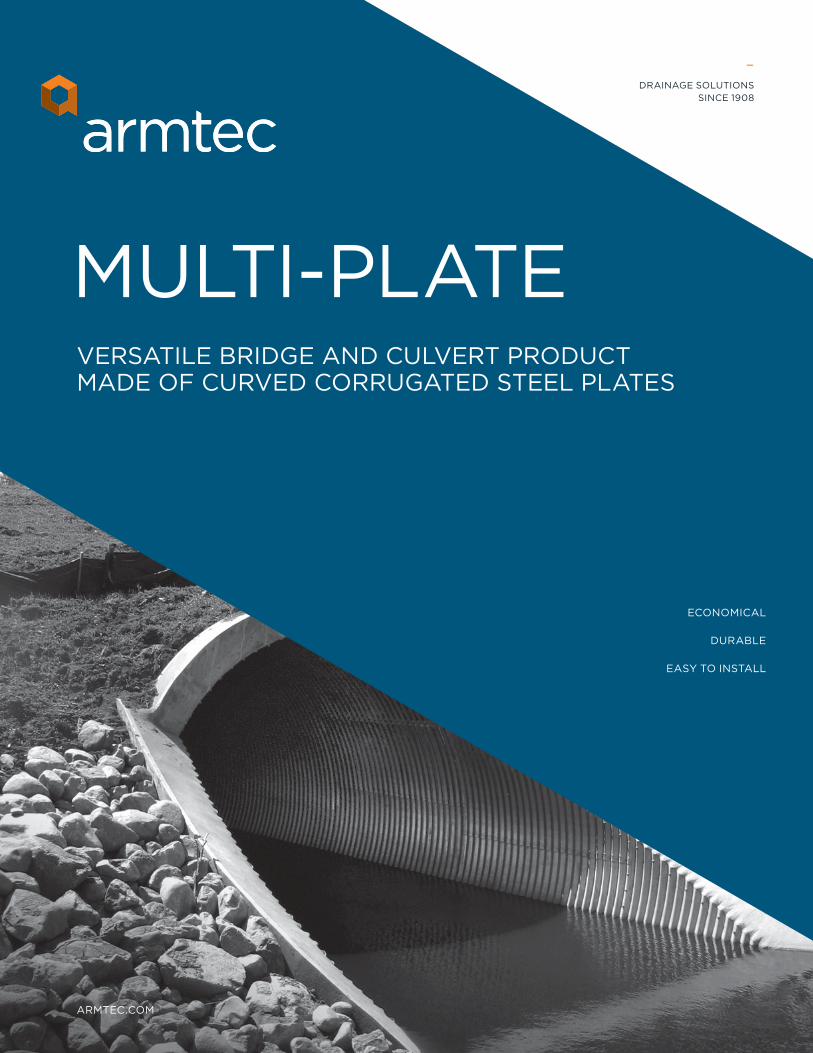
ARMTEC.COM – DRAINAGE SOLUTIONS SINCE 1908 MULTI-PLATE VERSATILE BRIDGE AND CULVERT PRODUCT MADE OF CURVED CORRUGATED STEEL PLATES ECONOMICAL DURABLE EASY TO INSTALL
Transcript of MULTI-PLATE - Armtec · armtec.com – drainage solutions since 1908 multi-plate versatile bridge...
ARMTEC.COM
–DRAINAGE SOLUTIONS
SINCE 1908
MULTI-PLATEVERSATILE BRIDGE AND CULVERT PRODUCT MADE OF CURVED CORRUGATED STEEL PLATES
ECONOMICAL
DURABLE
EASY TO INSTALL

2 VISIT ARMTEC.COM FOR MORE INFORMATION
CUSTOM FABRICATIONS AVAILABLE A VERSATILE PRODUCT WITH MANY APPLICATIONS
Multi-Plate is a versatile and economical bridge and culvert product that can be custom designed for almost any application. This Structural Plate Corrugated Steel Pipe (SPCSP) component system is made of specially designed curved and corrugated galvanized steel plates. Structures are easily assembled in the field and installed using light construction equipment. Spans up to 7 metres are available, depending on shape geometry. For shorter span applications, Mini Multi-Plate is offered in diameters from 800mm to 3,600mm.
Choosing a Multi-Plate buried soil-steel structure eliminates the bridge deck, approach slabs and expansion joints common in traditional bridge design, significantly reducing maintenance and total life cycle costs. Multi-Plate is most commonly used as the steel element of a buried soil-steel structure, but it can also be part of free-standing structures such as rock fall protection and portals, conveyer tunnels, aggregate storage bins, water intakes, caissons and more. Strata-CAT polymer coating is available for added protection in corrosive or acidic environments. With so many options available, you can count on Multi-Plate to stand up to your most challenging demands.
VARIETY OF OPTIONS
TRANSPORTATION EFFICIENCY
EASY INSTALLATION
OPTIMIZED DESIGN
• A variety of shapes and sizes as well as custom structures available
• Strata-CAT polymer coating can be applied for additional corrosion protection
• Shipped in component form, nested on trucks or in containers
• No specialized lifting equipment, tools or skills required
• Structures can be shop assembled and shipped as pre-finished units
• Engineered and manufactured to meet your specific project needs
• Plate thickness varies to accommodate applied loads
TYPICAL APPLICATIONS
• Culverts • Underpasses • Conveyor Tunnels • Bridges • Storm Sewers • Caissons • Mining Gangways and Portals • Stream Crossings • Intakes • Soil Void Forms • Aerial Galleries • Roof Ventilators • Power Plant Discharge Lines • Storage Bins
MULTI-PLATE MULTI-PLATE HAS A PROVEN HISTORY OF PERFORMANCE DATING BACK TO 1932
ARMTEC DRAINAGE SOLUTIONS 3
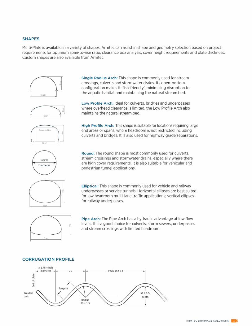
SHAPES
Multi-Plate is available in a variety of shapes. Armtec can assist in shape and geometry selection based on project requirements for optimum span-to-rise ratio, clearance box analysis, cover height requirements and plate thickness. Custom shapes are also available from Armtec.
Span
Ris
e
Ris
e
High Pro�le Arch Medium Pro�le Arch Low Pro�le Arch Standard Arch
Rc
Rsθ
α
β
Typical Arch Profile
Clearance Box
Span
Ris
e
Span
Ris
e
Span
Ris
e
Span
Ris
e
High Pro�le Arch Medium Pro�le Arch Low Pro�le Arch Standard ArchRc
Rsθ
α
β
Typical Arch Profile
Clearance Box
Span
Ris
e
SpanR
ise
Span
Ris
e
Span
Single Radius Arch: This shape is commonly used for stream crossings, culverts and stormwater drains. Its open-bottom configuration makes it ‘fish-friendly’, minimizing disruption to the aquatic habitat and maintaining the natural stream bed.
Low Profile Arch: Ideal for culverts, bridges and underpasses where overhead clearance is limited, the Low Profile Arch also maintains the natural stream bed.
High Profile Arch: This shape is suitable for locations requiring large end areas or spans, where headroom is not restricted including culverts and bridges. It is also used for highway grade separations.
Round: The round shape is most commonly used for culverts, stream crossings and stormwater drains, especially where there are high cover requirements. It is also suitable for vehicular and pedestrian tunnel applications.
Elliptical: This shape is commonly used for vehicle and railway underpasses or service tunnels. Horizontal ellipses are best suited for low headroom multi-lane traffic applications; vertical ellipses for railway underpasses.
Pipe Arch: The Pipe Arch has a hydraulic advantage at low flow levels. It is a good choice for culverts, storm sewers, underpasses and stream crossings with limited headroom.
CORRUGATION PROFILE
Inside
Diameter

4 VISIT ARMTEC.COM FOR MORE INFORMATION
COATINGS
Armtec Multi-Plate is available in a number of coating options to accommodate different environmental parameters and design service life (DSL) requirements. Multi-Plate components are hot-dip galvanized in accordance with CSA Standard G401 to provide a durable and corrosion resistant coating and can be applied in two different thicknesses (915 g/m2 and 1220 g/m2).
For extended service life and performance, Strata-CAT coating provides a two-coat polymer coating system. The base coat is a zinc-rich layer that provides outstanding corrosion resistance while the top-coat polymer layer provides superior resistance against impact, corrosion, abrasion and diluted inorganic acid or alkali. The Strata-CAT system is designed to provide a service life between 75 and 100 years, depending on environmental parameters.
STRATA-CAT POLYMER COATING PROVIDES EXTRA PROTECTION IN AGGRESSIVE ENVIRONMENTS
ELLIPTICAL STRUCTURES ARE IDEAL FOR SOFT FOUNDATIONS
THE OPEN BOTTOM ARCH PRESERVES THE
AQUATIC HABITAT
MULTI-PLATE PROVIDES SUPERIOR STRENGTH AND DURABILITY
ARMTEC DRAINAGE SOLUTIONS 5
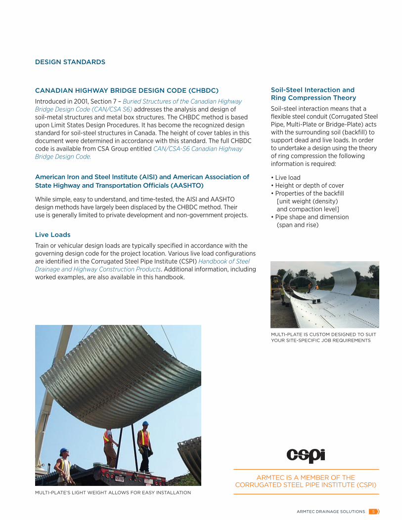
DESIGN STANDARDS
CANADIAN HIGHWAY BRIDGE DESIGN CODE (CHBDC)
Introduced in 2001, Section 7 – Buried Structures of the Canadian Highway Bridge Design Code (CAN/CSA S6) addresses the analysis and design of soil-metal structures and metal box structures. The CHBDC method is based upon Limit States Design Procedures. It has become the recognized design standard for soil-steel structures in Canada. The height of cover tables in this document were determined in accordance with this standard. The full CHBDC code is available from CSA Group entitled CAN/CSA-S6 Canadian Highway Bridge Design Code.
American Iron and Steel Institute (AISI) and American Association of State Highway and Transportation Officials (AASHTO)
While simple, easy to understand, and time-tested, the AISI and AASHTO design methods have largely been displaced by the CHBDC method. Their use is generally limited to private development and non-government projects.
Live Loads
Train or vehicular design loads are typically specified in accordance with the governing design code for the project location. Various live load configurations are identified in the Corrugated Steel Pipe Institute (CSPI) Handbook of Steel Drainage and Highway Construction Products. Additional information, including worked examples, are also available in this handbook.
MULTI-PLATE’S LIGHT WEIGHT ALLOWS FOR EASY INSTALLATION
MULTI-PLATE IS CUSTOM DESIGNED TO SUIT YOUR SITE-SPECIFIC JOB REQUIREMENTS
ARMTEC IS A MEMBER OF THE CORRUGATED STEEL PIPE INSTITUTE (CSPI)
Soil-Steel Interaction and Ring Compression Theory
Soil-steel interaction means that a flexible steel conduit (Corrugated Steel Pipe, Multi-Plate or Bridge-Plate) acts with the surrounding soil (backfill) to support dead and live loads. In order to undertake a design using the theory of ring compression the following information is required:
• Live load • Height or depth of cover • Properties of the backfill [unit weight (density) and compaction level] • Pipe shape and dimension (span and rise)

6 VISIT ARMTEC.COM FOR MORE INFORMATION
END TREATMENTS
End treatment for Multi-Plate structures is required or desirable for many reasons. These may include enhanced hydraulics, slope retention, aesthetics and protection against erosion, scour, piping, uplift, and ice damage.
SHEET PILE CUT-OFF WALLS
These are designed to prevent piping and scour at the inlet and outlet of pipes. They extend below the invert of the pipe, and up to one diameter width on each side. Normally cut-off walls do not extend above the spring line, and in the case of bevelled end pipes do not extend above the top of the bottom step of the bevel.
BEVELLED ENDS
These are generally provided in lengths of 3.05m, 3.66m or combinations of these two dimensions. Standard slopes are 1.5:1 and 2:1. Bevelled ends require additional structural support such as a concrete collar, tiebacks or thicker end plates. Special configurations are available upon request.
SQUARE END BEVELLED END
SHEET PILE HEADWALL
CONCRETE HEADWALLGEOCELL MECHANICALLY STABILIZED EARTH (MSE) WALL
_
NOTE:All headwalls may be configured with or without wingwalls. Examples of various types of end treatments are shown below.
CAST-IN-PLACE HEADWALL WITH SEGMENTAL BLOCK RETAINING WING WALL
WIRE MESH MSE WALL

ARMTEC DRAINAGE SOLUTIONS 7
NOTE:• N = 243.84mm (9.6”) • Weights based on 3,660mm plate lengths • All weights include bolts and nuts • All dimensions are to inside of the crest of the corrugation and all figures shown are subject to manufacturing tolerances as per CSA G401 • 5N, 6N and 9N designate number of circumferential hole spaces in plate
Nominal Inside
Diameter
Periphery Hole
Spaces End AreaNumber of Plates Per Ring
(for standard layout)
Nominal Weight of Structure (kg/m) Bolts included
for Specified Steel Thickness (mm)
mm N m² 5N 6N 9N Total 3.0mm 4.0mm 5.0mm 6.0mm 7.0mm
1,500 20 1.77 4 0 0 4 180 234 288 342 396
1,660 22 2.16 2 2 0 4 195 254 313 373 432
1,810 24 2.58 0 4 0 4 211 275 339 403 467
1,970 26 3.04 4 1 0 5 232 302 373 443 513
2,120 28 3.54 2 3 0 5 248 323 398 473 548
2,280 30 4.07 0 2 2 4 257 335 415 494 572
2,430 32 4.65 1 0 3 4 272 356 440 524 608
2,590 34 5.26 2 1 2 5 294 384 474 564 654
2,740 36 5.91 0 0 4 4 303 396 490 584 678
3,050 40 7.32 2 2 2 6 346 452 559 665 771
3,360 44 8.89 1 2 3 6 377 493 609 725 841
3,670 48 10.61 0 2 4 6 408 534 660 786 911
3,990 52 12.47 2 1 4 7 445 582 719 856 993
4,300 56 14.49 1 1 5 7 476 623 770 916 1,063
4,610 60 16.66 0 1 6 7 507 663 820 977 1,134
4,920 64 18.99 2 0 6 8 544 711 880 1,047 1,215
5,230 68 21.46 1 0 7 8 575 752 930 1,108 1,285
5,540 72 24.08 0 0 8 8 - 793 981 1,168 1,356
5,850 76 26.86 2 2 6 10 - 849 1,049 1,249 1,449
6,160 80 29.79 1 2 7 10 - - 1,100 1,309 1,519
6,470 84 32.87 0 2 8 10 - - 1,150 1,370 1,589
6,780 88 36.10 2 1 8 11 - - 1,210 1,440 1,671
7,090 92 39.48 1 1 9 11 - - - 1,501 1,741
7,400 96 43.01 0 1 10 11 - - - 1,561 1,812
7,710 100 46.70 2 0 10 12 - - - - 1,893
8,020 104 50.53 1 0 11 12 - - - - 1,963
Table 1: Round Pipe Technical Data
Inside
Diameter

8 VISIT ARMTEC.COM FOR MORE INFORMATION
NOTE:• N = 243.84mm (9.6”) • Weights based on 3,660mm plate lengths • All weights include bolts and nuts • All dimensions are to inside of the crest of the corrugation and all figures shown are subject to manufacturing tolerances as per CSA G401 • 5N, 6N and 9N designate number of hole spaces in plate • T = Top, C = Corner, B = Bottom
Nominal Dimensions
Periphery Hole
Spaces End Area
Number of Plates Per Ring(for standard layout)
5N 6N 9N
Nominal Weight of Structure (kg/m) Bolts included
for Specified Steel Thickness (mm)
Span mm
Rise mm
N m² T C B T C B T C B Total 3.0mm 4.0mm 5.0mm 6.0mm 7.0mm
2,060 1,520 24 2.49 0 2 1 0 0 0 1 0 0 4 210 274 339 403 467
2,240 1,630 26 2.90 1 2 1 1 0 0 0 0 0 5 232 302 373 443 513
2,440 1,750 28 3.36 0 2 0 2 0 1 0 0 0 5 248 323 398 473 548
2,590 1,880 30 3.87 1 2 0 0 0 1 1 0 0 5 263 343 423 503 583
2,690 2,080 32 4.49 2 2 0 1 0 1 0 0 0 6 285 371 458 544 630
3,100 1,980 34 4.83 0 2 0 1 0 0 1 0 1 5 294 384 474 564 654
3,400 2,010 36 5.28 0 2 1 1 0 1 1 0 0 6 316 412 508 604 700
3,730 2,290 40 6.61 0 2 0 0 0 2 2 0 0 6 346 452 559 665 771
3,890 2,690 44 8.29 1 2 1 0 0 1 2 0 0 7 384 501 618 735 852
4,370 2,870 48 9.76 0 2 1 1 0 0 2 0 1 7 414 541 669 795 922
4,720 3,070 52 11.38 0 2 0 0 0 1 3 0 1 7 445 582 719 856 993
5,050 3,330 56 13.24 0 2 2 2 0 1 2 0 0 9 - 638 787 936 1,085
5,490 3,530 60 15.10 1 2 0 0 0 0 3 0 2 8 - - 829 987 1,145
5,890 3,710 64 17.07 2 2 1 1 0 1 2 0 1 10 - - 897 1,067 1,237
6,250 3,910 68 19.18 2 2 0 0 0 2 3 0 1 10 - - 948 1,128 1,308
Table 2: Pipe ArchTechnical Data
ARMTEC DRAINAGE SOLUTIONS 9
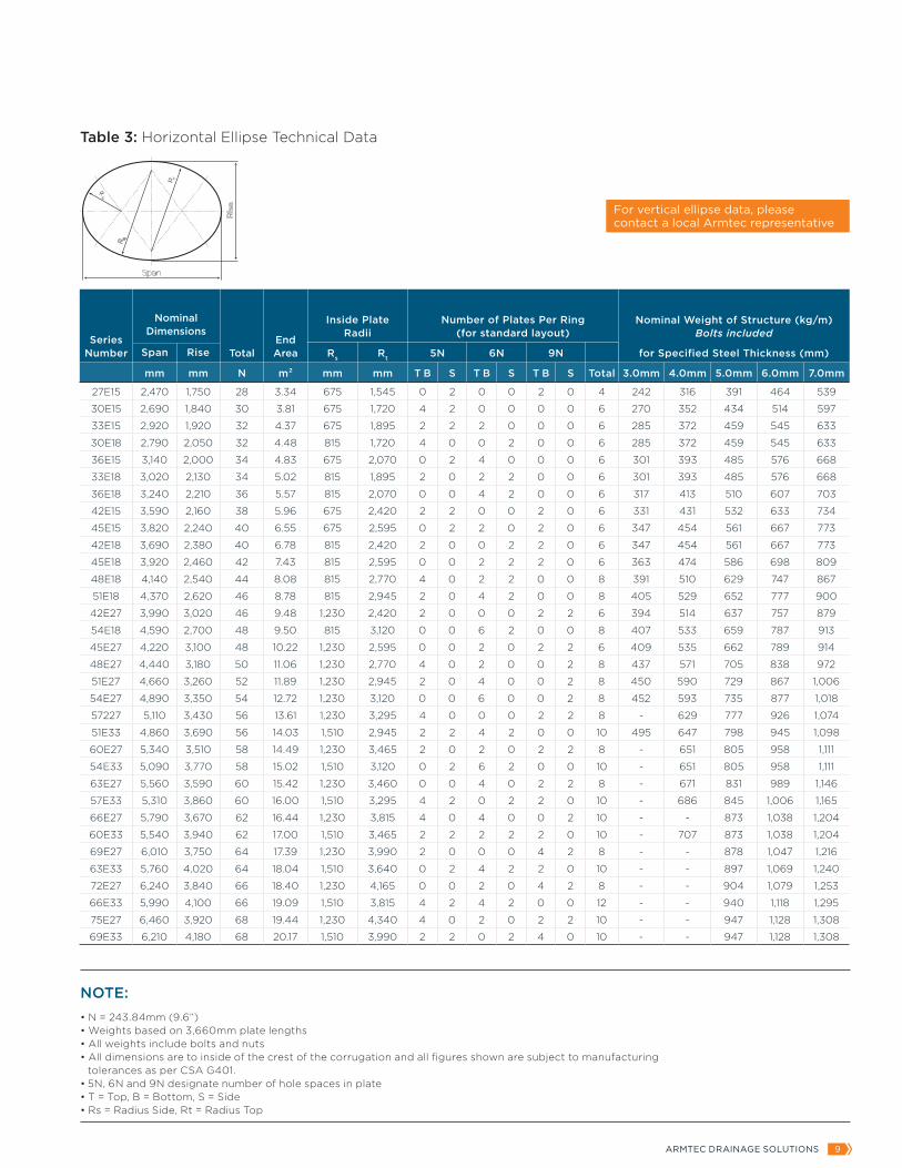
NOTE:• N = 243.84mm (9.6”) • Weights based on 3,660mm plate lengths • All weights include bolts and nuts • All dimensions are to inside of the crest of the corrugation and all figures shown are subject to manufacturing tolerances as per CSA G401. • 5N, 6N and 9N designate number of hole spaces in plate • T = Top, B = Bottom, S = Side • Rs = Radius Side, Rt = Radius Top
Series Number Span Rise Total
End Area
Inside Plate Radii
Number of Plates Per Ring(for standard layout)
Nominal Weight of Structure (kg/m) Bolts included
for Specified Steel Thickness (mm)Rs Rt 5N 6N 9N
mm mm N m² mm mm T B S T B S T B S Total 3.0mm 4.0mm 5.0mm 6.0mm 7.0mm
27E15 2,470 1,750 28 3.34 675 1,545 0 2 0 0 2 0 4 242 316 391 464 539
30E15 2,690 1,840 30 3.81 675 1,720 4 2 0 0 0 0 6 270 352 434 514 597
33E15 2,920 1,920 32 4.37 675 1,895 2 2 2 0 0 0 6 285 372 459 545 633
30E18 2,790 2,050 32 4.48 815 1,720 4 0 0 2 0 0 6 285 372 459 545 633
36E15 3,140 2,000 34 4.83 675 2,070 0 2 4 0 0 0 6 301 393 485 576 668
33E18 3,020 2,130 34 5.02 815 1,895 2 0 2 2 0 0 6 301 393 485 576 668
36E18 3,240 2,210 36 5.57 815 2,070 0 0 4 2 0 0 6 317 413 510 607 703
42E15 3,590 2,160 38 5.96 675 2,420 2 2 0 0 2 0 6 331 431 532 633 734
45E15 3,820 2,240 40 6.55 675 2,595 0 2 2 0 2 0 6 347 454 561 667 773
42E18 3,690 2,380 40 6.78 815 2,420 2 0 0 2 2 0 6 347 454 561 667 773
45E18 3,920 2,460 42 7.43 815 2,595 0 0 2 2 2 0 6 363 474 586 698 809
48E18 4,140 2,540 44 8.08 815 2,770 4 0 2 2 0 0 8 391 510 629 747 867
51E18 4,370 2,620 46 8.78 815 2,945 2 0 4 2 0 0 8 405 529 652 777 900
42E27 3,990 3,020 46 9.48 1,230 2,420 2 0 0 0 2 2 6 394 514 637 757 879
54E18 4,590 2,700 48 9.50 815 3,120 0 0 6 2 0 0 8 407 533 659 787 913
45E27 4,220 3,100 48 10.22 1,230 2,595 0 0 2 0 2 2 6 409 535 662 789 914
48E27 4,440 3,180 50 11.06 1,230 2,770 4 0 2 0 0 2 8 437 571 705 838 972
51E27 4,660 3,260 52 11.89 1,230 2,945 2 0 4 0 0 2 8 450 590 729 867 1,006
54E27 4,890 3,350 54 12.72 1,230 3,120 0 0 6 0 0 2 8 452 593 735 877 1,018
57227 5,110 3,430 56 13.61 1,230 3,295 4 0 0 0 2 2 8 - 629 777 926 1,074
51E33 4,860 3,690 56 14.03 1,510 2,945 2 2 4 2 0 0 10 495 647 798 945 1,098
60E27 5,340 3,510 58 14.49 1,230 3,465 2 0 2 0 2 2 8 - 651 805 958 1,111
54E33 5,090 3,770 58 15.02 1,510 3,120 0 2 6 2 0 0 10 - 651 805 958 1,111
63E27 5,560 3,590 60 15.42 1,230 3,460 0 0 4 0 2 2 8 - 671 831 989 1,146
57E33 5,310 3,860 60 16.00 1,510 3,295 4 2 0 2 2 0 10 - 686 845 1,006 1,165
66E27 5,790 3,670 62 16.44 1,230 3,815 4 0 4 0 0 2 10 - - 873 1,038 1,204
60E33 5,540 3,940 62 17.00 1,510 3,465 2 2 2 2 2 0 10 - 707 873 1,038 1,204
69E27 6,010 3,750 64 17.39 1,230 3,990 2 0 0 0 4 2 8 - - 878 1,047 1,216
63E33 5,760 4,020 64 18.04 1,510 3,640 0 2 4 2 2 0 10 - - 897 1,069 1,240
72E27 6,240 3,840 66 18.40 1,230 4,165 0 0 2 0 4 2 8 - - 904 1,079 1,253
66E33 5,990 4,100 66 19.09 1,510 3,815 4 2 4 2 0 0 12 - - 940 1,118 1,295
75E27 6,460 3,920 68 19.44 1,230 4,340 4 0 2 0 2 2 10 - - 947 1,128 1,308
69E33 6,210 4,180 68 20.17 1,510 3,990 2 2 0 2 4 0 10 - - 947 1,128 1,308
Table 3: Horizontal Ellipse Technical Data
For vertical ellipse data, please contact a local Armtec representative
Nominal Dimensions

10 VISIT ARMTEC.COM FOR MORE INFORMATION
Span Rise
Periphery Hole
Spaces
Water Way Area Radius
Number of Plates Per Ring(for standard layout)
Nominal Weight of Structure (kg/m) Bolts included
for Specified Steel Thickness (mm)
mm mm N m² mm 5N 6N 9N Total 3.0mm 4.0mm 5.0mm 6.0mm 7.0mm
1,520 810 10 0.98 760 2 0 0 2 87 114 141 168 195
1,830 840 11 1.16 930 1 1 0 2 95 124 154 183 213
970 12 1.39 910 0 2 0 2 102 134 166 198 230
2,130 860 12 1.39 1,090 0 2 0 2 102 134 166 198 230
1,120 14 1.86 1,070 1 0 1 2 118 155 192 229 266
2,440 1,020 14 1.86 1,230 1 0 1 2 118 155 192 229 266
1,270 16 2.42 1,220 2 1 0 3 139 183 226 269 312
2,740 1,180 16 2.46 1,400 2 1 0 3 139 183 226 269 312
1,440 18 3.07 1,370 0 0 2 2 148 195 242 289 336
3,050 1,350 18 3.16 1,540 0 0 2 2 148 195 242 289 336
1,600 20 3.81 1,520 1 1 1 3 170 223 276 329 382
3,350 1,360 19 3.44 1,710 2 0 1 3 163 213 264 314 365
1,750 22 4.65 1,680 2 2 0 4 192 251 310 370 429
3,660 1,520 21 4.18 1,850 0 2 1 3 178 233 289 344 400
1,910 24 5.48 1,830 0 1 2 3 201 264 327 390 453
3,960 1,680 23 5.02 2,010 1 3 0 4 203 264 326 388 449
2,060 26 6.50 1,980 1 2 1 4 223 292 361 430 499
4,270 1,840 25 5.95 2,160 2 1 1 4 215 282 348 415 481
2,210 28 7.43 2,130 2 0 2 4 238 312 386 460 534
4,570 1,870 26 6.41 2,340 1 2 1 4 223 292 361 430 499
2,360 30 8.55 2,290 0 2 2 4 254 332 412 491 569
4,880 2,030 28 7.43 2,480 2 0 2 4 238 312 386 460 534
2,520 32 9.75 2,440 1 0 3 4 - 353 437 521 605
5,180 2,180 30 8.55 2,620 0 2 2 4 - 332 412 491 569
2,690 34 11.06 2,590 2 1 2 5 - 381 471 561 654
5,490 2,210 31 9.01 2,820 2 2 1 5 - 350 433 516 598
2,720 35 11.71 2,740 1 2 2 5 - 391 484 576 669
5,790 2,360 33 10.22 2,5.90 0 1 3 4 - - 450 536 622
2,880 37 13.01 2,900 2 0 3 5 - - 509 606 704
6,100 2,530 35 11.52 3,100 1 2 2 5 - - 484 576 669
3,050 39 14.59 3,050 0 2 3 5 - - 534 637 739
Span
Footing Channel
of Bolt
Ris
e
116
30
86
40
4.2
76
38 38
R
c
of Boltc
NOTE:• N = 243.84mm (9.6”) • Weights based on 3,660mm plate lengths • All weights include bolts and nuts • All dimensions are to inside of the crest of the corrugation and all figures shown are subject to manufacturing tolerances as per CSA G401 • 5N, 6N and 9N designate number of hole spaces in plate
Table 4: Arch Pipe Arch Technical Data
Nominal Dimensions

ARMTEC DRAINAGE SOLUTIONS 11
NOTE: • N = 243.84mm (9.6”) • Weights based on 3,660mm plate lengths • All weights include bolts and nuts • All dimensions are to inside of the crest of the corrugation and all figures shown are subject to manufacturing tolerances as per CSA G401 • 5N, 6N and 9N designate number of hole spaces in plate • T = Top, S = Side, C = Corner, B = Bottom
Nominal Dimensions Periphery
Hole Spaces End Area
Bottom Dimension
Inside Plate Radii
Number of Plates Per Ring(for standard layout)
Span Rise Rt Rs Rc Rb 5N 6N 9N
mm mm N m² mm mm mm mm mm T S C B T S C B T S C B Total
3,750 3,340 47 10.0 1,210 1,700 2,135 1,065 3,405 0 0 2 2 0 0 0 0 1 2 0 0 7
3,880 3,520 49 10.8 1,220 1,675 2,440 1,040 3,380 2 0 2 1 0 0 0 1 0 2 0 0 8
3,980 3,700 51 11.8 1,240 1,780 2,540 1,065 3,580 0 0 2 1 2 0 0 1 0 2 0 0 8
4,060 3,900 53 12.8 1,260 1,830 2,795 1,090 3,680 1 0 2 1 0 0 0 1 1 2 0 0 8
4,110 3,980 54 13.3 1,280 1,880 2,845 1,120 3,785 0 0 2 1 1 0 0 1 1 2 0 0 8
4,200 4,060 55 13.7 1,290 1,880 3,125 1,090 3,760 0 0 2 0 1 0 0 2 1 2 0 0 8
4,510 4,090 57 14.7 1,300 1,980 3,300 1,040 3,990 0 0 2 1 1 0 0 0 1 2 0 1 8
4,660 4,220 59 15.8 1,340 2,110 3,020 1,090 4,240 0 4 2 1 1 0 0 0 1 0 0 1 10
4,730 4,380 61 16.7 1,240 2,100 3,605 1,015 5,260 1 4 2 1 2 0 0 0 0 0 0 1 11
4,820 4,580 63 17.9 1,260 2,135 3,630 1,040 5,310 1 2 2 1 2 2 0 0 0 0 0 1 11
4,990 4,710 65 19.0 1,280 2,210 3,935 1,040 5,485 0 2 2 0 0 2 0 1 2 0 0 1 10
5,110 4,820 67 20.2 1,240 2,335 3,630 1,065 7,265 2 0 2 1 0 4 0 0 1 0 0 1 11
5,250 4,840 68 20.8 1,240 2,390 3,685 1,040 7,085 2 0 2 0 0 4 0 1 1 0 0 1 11
5,380 5,130 70 22.3 1,580 2,440 3,760 1,345 5,205 2 0 0 0 0 4 2 1 1 0 0 1 12
5,500 5,240 72 23.3 1,400 2,390 4,775 1,170 6,655 1 0 0 2 1 4 2 1 1 0 0 0 12
5,790 5,310 74 24.9 1,600 2,665 3,935 1,320 5,810 0 0 0 1 2 4 2 2 1 0 0 0 12
5,950 5,430 76 26.2 1,580 2,690 3,860 1,320 6,655 2 2 0 1 0 0 2 2 1 2 0 0 12
6,090 5,590 78 27.5 1,580 2,720 4,190 1,295 6,730 1 2 0 0 1 0 2 0 1 2 0 2 11
6,280 5,690 80 29.0 1,620 2,920 3,960 1,345 7,135 2 2 0 0 2 0 2 0 0 2 0 2 12
Table 5: Underpass Technical Data

12 VISIT ARMTEC.COM FOR MORE INFORMATION
1. FOUNDATION PREPARATION
Soil-steel structures depend upon the inherent flexibility of the steel shell to accommodate small deflections and fully mobilize the support of the granular backfill. A compressible soil cushion is installed under the invert of the pipe to allow the corrugations to settle into the granular material while providing sufficient load-bearing capacity to support the pipe, fill, and other applied loads.
Haunches
Installation may be aided by placing the cushion on a pre-shaped bed for shapes with tight corner or side radii, such as pipe-arch, underpass, or horizontal ellipse shapes, to provide better compaction.
Arches
Plates are typically secured to a concrete strip footing. An Armtec supplied unbalanced channel is anchored to the footing in order to receive the plates.
2. ASSEMBLY
Multi-Plate assembly is accomplished by bolting adjacent longitudinal and circumferential plates to form the full length and circumference of the structure. All structures are supplied with engineering drawings showing the correct positioning of the plates, plate lapping details, as well as comprehensive backfilling instructions.
Field Construction
Assembly may be undertaken plate-by-plate, or by sub-assembling arcs of the structure before lifting into the excavation to minimize field construction time.
Typical assembly tools
• Spud wrenches • Clevises • Cables and slings • Air impact tools • Turnbuckles • Eyebolts • Alignment pins, prybars
3. BACKFILL AND COMPACTION
Free draining granular materials shall be used in the engineered backfill envelope. Backfill shall be placed in 200mm lifts and compacted to a minimum of 95% Standard Proctor Dry Density.
Typical equipment required for backfilling in critical backfill zone
• Small tracked/wheeled equipment for spreading • Walk-behind compactor • Vibrating plate tampers • Ride-on compactor up to 15 tonnes (where feasible) • Tracked (D6) equipment for spreading material when backfill is more than 1.5m above structure • Water supply • Shovels/rakes/other equipment as appropriate for available manpower • Material supply by truck as required
INSTALLATION
Fabricated from factory-curved corrugated steel plates, Multi-Plate is a field-assembled flexible soil-steel structure. As with any buried structure, proper installation is critical in providing long-term and worry-free performance of the structure. In practical terms, installation can be broken into three major operations:
QUALITY CHECKS IN THE PLANT ENSURE THERE ARE NO SURPRISES IN THE FIELD
MULTI-PLATE RECLAIM PILE CONVEYOR TUNNEL
_
NOTE:Armtec Recommended Installation Guidelines are provided for assembling Multi-Plate. Drawings, including the unbalanced channel layout for arches are provided and will vary depending upon the shape and complexity of the installation.
ARMTEC DRAINAGE SOLUTIONS 13
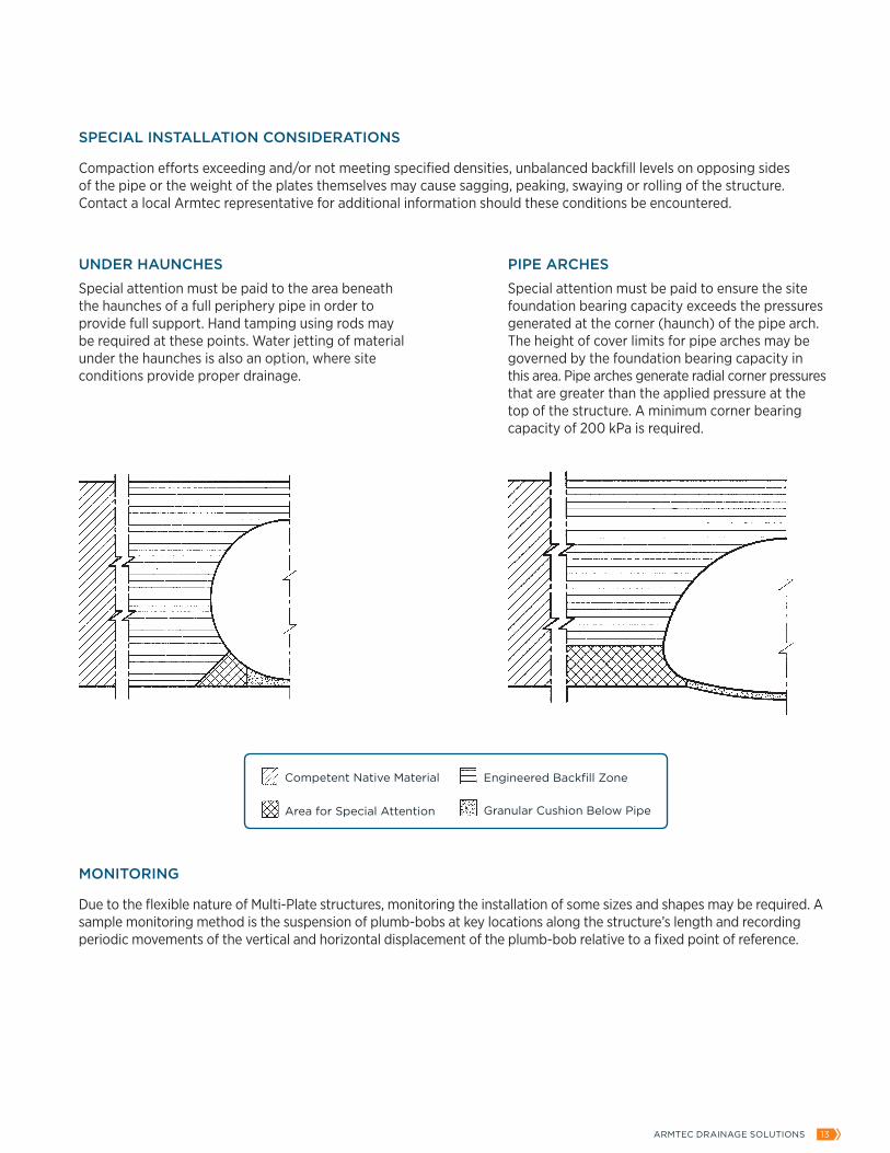
SPECIAL INSTALLATION CONSIDERATIONS
Compaction efforts exceeding and/or not meeting specified densities, unbalanced backfill levels on opposing sides of the pipe or the weight of the plates themselves may cause sagging, peaking, swaying or rolling of the structure. Contact a local Armtec representative for additional information should these conditions be encountered.
MONITORING
Due to the flexible nature of Multi-Plate structures, monitoring the installation of some sizes and shapes may be required. A sample monitoring method is the suspension of plumb-bobs at key locations along the structure’s length and recording periodic movements of the vertical and horizontal displacement of the plumb-bob relative to a fixed point of reference.
UNDER HAUNCHES
Special attention must be paid to the area beneath the haunches of a full periphery pipe in order to provide full support. Hand tamping using rods may be required at these points. Water jetting of material under the haunches is also an option, where site conditions provide proper drainage.
PIPE ARCHES
Special attention must be paid to ensure the site foundation bearing capacity exceeds the pressures generated at the corner (haunch) of the pipe arch. The height of cover limits for pipe arches may be governed by the foundation bearing capacity in this area. Pipe arches generate radial corner pressures that are greater than the applied pressure at the top of the structure. A minimum corner bearing capacity of 200 kPa is required.
Competent Native Material
Area for Special Attention
Engineered Backfill Zone
Granular Cushion Below Pipe
14 VISIT ARMTEC.COM FOR MORE INFORMATION
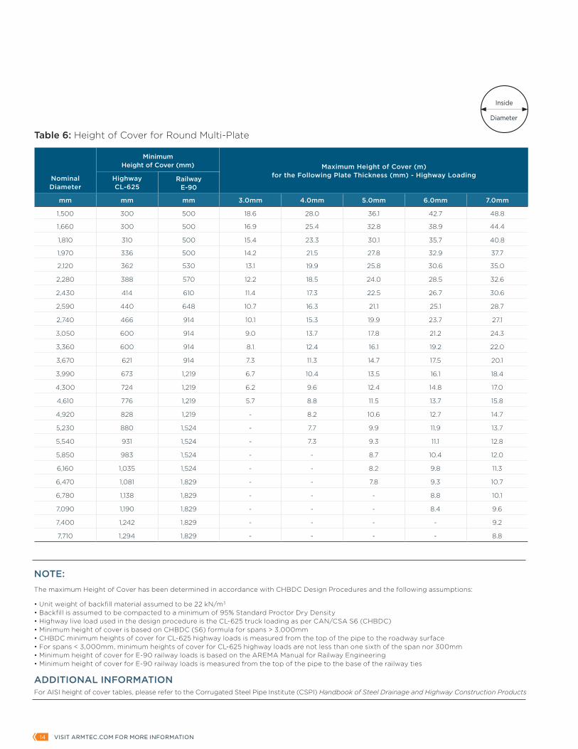
Nominal Diameter
Minimum Height of Cover (mm) Maximum Height of Cover (m)
for the Following Plate Thickness (mm) - Highway LoadingHighwayCL-625
RailwayE-90
mm mm mm 3.0mm 4.0mm 5.0mm 6.0mm 7.0mm
1,500 300 500 18.6 28.0 36.1 42.7 48.8
1,660 300 500 16.9 25.4 32.8 38.9 44.4
1,810 310 500 15.4 23.3 30.1 35.7 40.8
1,970 336 500 14.2 21.5 27.8 32.9 37.7
2,120 362 530 13.1 19.9 25.8 30.6 35.0
2,280 388 570 12.2 18.5 24.0 28.5 32.6
2,430 414 610 11.4 17.3 22.5 26.7 30.6
2,590 440 648 10.7 16.3 21.1 25.1 28.7
2,740 466 914 10.1 15.3 19.9 23.7 27.1
3,050 600 914 9.0 13.7 17.8 21.2 24.3
3,360 600 914 8.1 12.4 16.1 19.2 22.0
3,670 621 914 7.3 11.3 14.7 17.5 20.1
3,990 673 1,219 6.7 10.4 13.5 16.1 18.4
4,300 724 1,219 6.2 9.6 12.4 14.8 17.0
4,610 776 1,219 5.7 8.8 11.5 13.7 15.8
4,920 828 1,219 - 8.2 10.6 12.7 14.7
5,230 880 1,524 - 7.7 9.9 11.9 13.7
5,540 931 1,524 - 7.3 9.3 11.1 12.8
5,850 983 1,524 - - 8.7 10.4 12.0
6,160 1,035 1,524 - - 8.2 9.8 11.3
6,470 1,081 1,829 - - 7.8 9.3 10.7
6,780 1,138 1,829 - - - 8.8 10.1
7,090 1,190 1,829 - - - 8.4 9.6
7,400 1,242 1,829 - - - - 9.2
7,710 1,294 1,829 - - - - 8.8
Table 6: Height of Cover for Round Multi-Plate
NOTE:The maximum Height of Cover has been determined in accordance with CHBDC Design Procedures and the following assumptions:
• Unit weight of backfill material assumed to be 22 kN/m3 • Backfill is assumed to be compacted to a minimum of 95% Standard Proctor Dry Density • Highway live load used in the design procedure is the CL-625 truck loading as per CAN/CSA S6 (CHBDC) • Minimum height of cover is based on CHBDC (S6) formula for spans > 3,000mm • CHBDC minimum heights of cover for CL-625 highway loads is measured from the top of the pipe to the roadway surface • For spans < 3,000mm, minimum heights of cover for CL-625 highway loads are not less than one sixth of the span nor 300mm • Minimum height of cover for E-90 railway loads is based on the AREMA Manual for Railway Engineering • Minimum height of cover for E-90 railway loads is measured from the top of the pipe to the base of the railway ties
ADDITIONAL INFORMATIONFor AISI height of cover tables, please refer to the Corrugated Steel Pipe Institute (CSPI) Handbook of Steel Drainage and Highway Construction Products
Inside
Diameter

ARMTEC DRAINAGE SOLUTIONS 15
NOTE:The maximum Height of Cover has been determined in accordance with CHBDC Design Procedures and the following assumptions:
• Unit weight of backfill material assumed to be 22 kN/m3 • Backfill is assumed to be compacted to a minimum of 95% Standard Proctor Dry Density • Highway live load used in the design procedure is the CL-625 truck loading as per CAN/CSA S6 (CHBDC) • Minimum height of cover is based on CHBDC (S6) formula for spans > 3,000mm • CHBDC minimum heights of cover for CL-625 highway loads is measured from the top of the pipe to the roadway surface • For spans < 3,000mm, minimum heights of cover for CL-625 highway loads are not less than one sixth of the span nor 300mm
ADDITIONAL INFORMATIONFor AISI height of cover tables, please refer to the Corrugated Steel Pipe Institute (CSPI) Handbook of Steel Drainage and Highway Construction Products
Span Rise Minimum CoverMinimum Thickness
Maximum Cover (m)Restrict Corner Pressure to the Following Value
mm mm mm mm 100 kPa 200 kPa 300 kPa 400 kPa
2,050 1,520 350 3.0 2.9 6.0 9.1 12.2
2,240 1,630 383 3.0 2.7 5.6 8.6 11.5
2,440 1,750 415 3.0 2.5 5.4 8.2 11.0
2,590 1,880 441 3.0 2.5 5.4 8.2 11.0
2,690 2,080 458 3.0 2.8 5.9 8.9 11.9
3,100 1,920 669 3.0 1.9 4.1 6.3 8.4
3,400 2,010 850 3.0 1.4 3.3 5.1 6.9
3,730 2,290 731 3.0 1.5 3.5 5.3 7.2
3,890 2,690 683 3.0 1.9 4.2 6.4 8.6
4,370 2,870 801 3.0 1.6 3.6 5.6 7.5
4,720 3,070 853 3.0 1.5 3.4 5.2 7.0
5,050 3,330 891 3.0 1.5 3.3 5.0 6.8
5,490 3,530 977 3.0 1.3 3.0 4.6 6.2
5,890 3,710 1,064 3.0 1.2 2.58 4.3 5.8
6,250 3,910 1,108 4.0 1.1 2.6 4.1 5.5
Table 7: Height of Cover for Pipe Arch Multi-Plate
Nominal Dimensions
Constructing soil-steel bridges with Armtec Multi-Plate allows the roadway subgrade to extend directly overtop the buried bridge elements. The uniform subgrade construction supports a continuous and seamless pavement structure with consistent roadside thermal properties. Eliminating differential pavement materials (and properties) reduces the risk of abrupt patches of ice forming on the road surface above the bridge, improving driver safety.
The overburden separating the top of soil-steel structures from the travelled road surface shields the buried bridge components from the damaging dynamic load effects highway traffic imposes on the structure. Life cycle costs associated with maintaining bridge decks, bearings, fatigue and fractures, expansion joints and approach slabs are eliminated whenever buried bridges utilizing a soil-steel interaction are selected.

16 VISIT ARMTEC.COM FOR MORE INFORMATION
Span Rise
Minimum Height of Cover Maximum Height of Cover (m)
for the Following Plate Thickness (mm) - Highway LoadingHighwayCL-625
mm mm mm 3.0mm 4.0mm 5.0mm 6.0mm 7.0mm
1,520 810 300 18.4 27.7 35.7 42.2 48.2
1,830 840 315 15.1 22.8 29.5 35.0 40.0
970 315 15.4 23.2 30.0 35.5 40.6
2,130 860 370 13.1 19.8 25.6 30.4 34.8
1,120 370 13.0 19.7 25.6 30.3 34.7
2,440 1,030 420 11.5 17.4 22.5 26.8 30.6
1,270 420 11.4 17.3 22.4 26.6 30.5
2,740 1,180 475 10.0 15.2 19.8 23.5 26.9
1,440 475 10.1 15.4 19.9 23.7 27.1
3,050 1,340 600 9.0 13.7 17.8 21.2 24.3
1,600 600 9.0 13.8 17.9 21.3 24.4
3,350 1,360 600 8.1 12.5 16.2 19.3 22.1
1,750 600 8.1 12.4 16.1 19.2 22.0
3,660 1,520 625 7.4 11.4 14.8 17.7 20.3
1,910 625 7.4 11.4 14.7 17.6 20.2
3,960 1,680 680 6.7 10.4 13.5 16.1 18.5
2,060 680 6.7 10.4 13.5 16.2 18.6
4,270 1,840 730 6.2 9.6 12.5 14.9 17.1
2,210 730 6.2 9.6 12.5 14.9 17.2
4,570 1,870 790 5.8 8.9 11.5 13.8 15.9
2,360 790 5.8 8.9 11.5 13.8 15.9
4,880 2,030 835 5.4 8.3 10.8 12.9 14.8
2,520 835 5.4 8.3 10.7 12.9 14.8
5,180 2,180 882 5.1 7.8 10.1 12.1 13.9
2,690 882 5.1 7.8 10.0 12.0 13.8
5,490 2,210 950 4.8 7.3 9.3 11.2 12.9
2,720 950 4.8 7.3 9.4 11.3 13.0
5,790 2,360 990 - 7.0 8.8 10.6 12.2
2,880 990 - 6.9 8.8 10.5 12.2
6,100 2,530 1,040 - 6.6 8.4 9.9 11.5
3,035 1,040 - 6.6 8.3 9.9 11.5
Table 8: Height of Cover for Arch Multi-PlateSpan
Footing Channel
of Bolt
Ris
e
116
30
86
40
4.2
76
38 38
R
c
of Boltc
Nominal Dimensions
NOTE:The maximum Height of Cover has been determined in accordance with CHBDC Design Procedures and the following assumptions:
• Unit weight of backfill material assumed to be 22 kN/m3 • Backfill is assumed to be compacted to a minimum of 95% Standard Proctor Dry Density • Highway live load used in the design procedure is the CL-625 truck loading as per CAN/CSA S6 (CHBDC) • Minimum height of cover is based on CHBDC (S6) formula for spans > 3,000mm • CHBDC minimum height of cover for CL-625 highway loads is measured from the top of the pipe to the roadway surface • For spans < 3,000mm, minimum height of cover for CL-625 highway loads is not less than one sixth of the span nor 300mm
ADDITIONAL INFORMATIONFor AISI height of cover tables, please refer to the Corrugated Steel Pipe Institute (CSPI) Handbook of Steel Drainage and Highway Construction Products

ARMTEC DRAINAGE SOLUTIONS 17
Typical Specification for Multi-Plate Structure
1. General
1.1 This specification is for _________[number of structures] of _________ mm span x _________ mm rise galvanized Armtec Multi-Plate structure[s]. The length is ________m with a nominal plate thickness of________mm.
1.2 Proposed product delivery and construction schedules shall be communicated to all parties.
1.3 Armtec shall submit Multi-Plate Assembly Drawings and Installation Guidelines prior to the commencement of construction.
1.4 Armtec Installation Guidelines are intended to be used in conjunction with the project specifications and are not to supersede them.
1.5 All earthworks, de-watering, site works and plate assembly are performed by the contractor.
1.6 Construction shall comply with the project specifications and drawings including the Armtec Assembly Drawings.
1.7 Monitoring compliance with point 1.6 and inspection of works will be the responsibility of the Owner’s Project Management team.
2. Products
2.1 Multi-Plate sheet and plate shall be fabricated in accordance with CSA G401 Corrugated Steel Pipe Products.
2.2 Each Multi-Plate sheet shall be hot dip galvanized in accordance with CSA G401 with a zinc mass as specified in CSA G401 unless an alternate coating mass is specified.
2.3 The nominal plate thickness shall be ________ mm.
3. Assembly of Plates
3.1 Offloading of the Multi-Plate at the job site is the responsibility of the Owner.
3.2 The Owner, during plate assembly and placement of backfill, shall provide a dry and accessible work site and excavation area.
3.3 A qualified contractor, who has a minimum of five years experience in similar work, shall perform the Multi-Plate assembly.
3.4 The structure shall be assembled in accordance with the Armtec Assembly Instructions provided.
3.5 Bolting must be done with the curved surface of the nut against the plate.
3.6 Before backfilling, all bolts shall be tightened to a torque between 200 and 350Nm (150 to 250ft-lbs).
4. Armtec Supervision (optional)
4.1 Armtec will provide an experienced Site Inspector to supervise construction at the following key times (at the option of the owner) at an agreed upon interval:
4.1.1 Start of plate assembly.
4.1.2 Prior to the commencement of backfilling (assembled structure shape check).
4.1.3 Start of critical backfill placement.
4.1.4 During backfill placement (shape monitoring).
4.1.5 When initial covering and crossing of backfill and equipment over the structure takes place.
4.1.6 During backfill/cover placement to final grade.
4.2 The Armtec Site Inspector shall have full Stop Work authority for when Armtec Installation Instructions or procedures are not being followed or when the shape monitoring program indicates that backfilling should temporarily cease.
5. Winter Construction
5.1 Winter construction shall be avoided whenever possible.
5.2 If winter construction is required, special conditions for cold weather construction must be followed. An Armtec representative must be consulted for further details.
_
NOTE:Polymer coating can be specified as per the Strata-CAT product guide. Please contact an Armtec representative for more information.

18 VISIT ARMTEC.COM FOR MORE INFORMATION
CONTACT INFORMATION:
Project Name and Location:
Contact and Company Name:
Email:
Telephone:
BASIC PROJECT INFORMATION:STEP 1: SELECT STRUCTURE SHAPE
Is this a reline project? Yes No EXISTING SHAPE INFORMATION _______________
STEP 2: PROVIDE DIMENSIONSHeight of Cover ______________
Rise _______________________
Span ______________________
Live Loading ________________
STEP 3: COATING SPECIFICATION 915 g/m2 GALVANIZED STEEL STRATA-CAT COATING (POLYMER COATED)
1220 g/m2 GALVANIZED STEEL BLACK STEEL
SINGLE RADIUS ARCH
LOW PROFILE ARCH PIPE ARCH UNDERPASS VERTICAL ELLIPSE
HIGH PROFILE ARCH ROUND HORIZONTAL ELLIPSE
MULTI-PLATE PROJECT INQUIRY SHEET

ARMTEC DRAINAGE SOLUTIONS 19
1. Minimum Span _________m
2. Application Culvert Bridge Stream Crossing Mine Portal Grade Separation Other_____
Vertical height clearance (road elevation or streambed/road elevation):
_________m
Is this requirement flexible: Yes No
3. Scour Depth __________m or unknown
4. Live Load Vehicle __________or assume CL-625 overload conditions
5. Soil Density __________ kN/m3 or assume 22 kN/m3 as per CHBDC
6. Required Hydraulic End Area __________ m2
7. Clearance Box Requirements __________m (span x height)
Clearance Box Chamber: __________m (width x length)
8. Corrosive Environment Yes No
Specified Service Life: 50 years 75 years Other _____________
9. Seismic Analysis Available Yes No
Site Locations: ____________________________________________
Or, Zonal Acceleration Ratio: __________________________________
10. End Treatment Requirements Yes No
Square End or Bevel End (specify slope):__________________________
Note: minimum requirement is Cast-in-Place Concrete End Collar as per CHBDC
Structure Skewed To: Road Unbalanced Fill
Are Head and/or Wingwalls required?: Yes No
Material for Headwalls and/or Wingwalls: Armtec Steel Face Wall
Armtec Bin-Wall
Armtec Wire Mesh (MSE) Wall - Please specify face material type (i.e. rock or vegetated)
Other (specify)
11. Geotechnical Report Available: Yes No
12. Allowable Bearing Capacity: ______ kPa
SITE SPECIFIC INFORMATION AVAILABLE

–Armtec is a leading Canadian infrastructure and construction materials company combining creative engineered solutions, relevant advice, dedicated people, proven products and a national presence with a local focus on exceptional customer service.
1-877-5-ARMTEC | ARMTEC.COM
–Drawings and product details are for information and/or illustrative purposes only, and may vary. Please contact your local Armtec representative for the most current product information.–MULTI-PLATE / PRODUCT GUIDE | 2016-09PROD-C02-G6-PG-2016-09-E