Deepa Bajaj , Navneet Verma2 - ijaret.org Secret Sharing Scheme.pdfWebpage: ...

MULTI-OBJECTIVE VAR PLANNING WITH SVC USINGPARTICLE SWARM OPTIMIZATION TECHNIQUES IN
POWER SYSTEM NETWORKS
Bindeshwar Singh1, K. S. Verma2, Deependra Singh3 & S. N. Singh4
1,2,3Member, IEEE4Senior Member, IEEE
Abstract: This paper presents a novel muti-objective evolutionary computational approach such as Particle Swarm Optimization(PSO) technique proposed for optimal placement of Static Var Compensator (SVC) form the different performance parametersof power systems viewpoint such as minimize the active power losses and cost of system, improve the voltage profile, increasethe loadability of systems, and provide the reactive power support in emergency case such fault occur or suddenly change infield excitation of alternators, or suddenly load increased in power systems. The proposed technique such as PSO is alsoapplicable for optimal placement of other FACTS controllers such as TCSC, SSSC, STATCOM, UPFC, GUPFC, and IPFC insimilar fashion from different performance parameters viewpoints. Simulations are proposed to performed in the next paperon IEEE-9, and IEEE-59, and IEEE-14 bus systems for optimal location of FACTS devices and the results obtained areencouraging and will be useful in electrical restructuring.
Index Terms: Flexible AC Transmission Systems (FACTS), FACTS Controllers, SVC, Particle Swarm Optimization (PSO)technique, Power Systems.
NOMENCLATUREkiv : Velocity of agent i at kth iteration
1kiv � : Velocity of agent i at (k + 1)th iteration
w : The inertia weight
1 2&c c : Individual and social acceleration Constants (0 to 3)
1 2&rand rand : Random numbers (0 to 1)
kis : Current position of agent i at kth iteration
1kis � : Current position of agent i at (k+1)th
iteration
pbesti : Particle best of agent i
gbest : Global best of the group
itermax : Maximum iteration number
iter : Current iteration number
I. INTRODUCTION
In the past decade, the problem of reactive power control forimproving economy and security of power system operationhas received much attention. Generally, the load bus voltagescan be maintained within their permissible limits byreallocating reactive power generations in the system. Thiscan achieve by adjusting transformer taps, generatorvoltages, and switchable VAR sources. In addition, the
system losses can be minimized via redistribution of reactivepower in the system. Therefore, the problem of the reactivepower dispatch can be optimized to improve the voltageprofile and minimize the system losses as well. Severalmethods to solve the optimal reactive power dispatchproblem have been proposed in the open literatures.
With the worldwide restructuring and deregulation ofpower systems, sufficient transmission capacity and reliableoperation have become more valuable to both systemplanners and operators. Building new constructions toenhance the loadability of a network is very expensive andmany constraints have to be satisfied. As a result, there is asignificantly increased potential for the application of FACTSdevices due to their important role in power system securityenhancement. Among the FACTS devices, Static VArCompensators (SVCs) are widely used around the world bothfor their capabilities and for their low maintenance costs.Although investment cost of SVCs are expensive butmaintenance costs are low since the devices have no movingparts and repairs are minimal.
SVC is a first generation FACTS device. SVCs areextensively employed in power system since 1970s. Theyare applied by utilities in transmission applications forseveral purposes. The primary purpose is usually the rapidcontrol of voltage at weak nodes in power system networks.SVCs are also used for:
I J E E S R • Vol. 3 � No. 2 � July-December 2013, pp. 51-59

52 I J E E S R
� Increasing power transfer capacity in long lines.
� Stability improvement (both transient and dynamic)with fast acting voltage regulation.
� Damping of low power frequency oscillations(corresponding to electro-mechanical modes).
� Damping of sub-synchronous oscillations (due totorsional modes).
� Control of dynamic overvoltages.
Basic Optimal FACTS Allocation problem has beensolved by various optimization techniques and differentobjective functions. In general optimal FACTS allocationproblem is to determine the optimal size and location of newinstalled FACTS devices in order to optimize a specificobjective function while considering variety of operatingconstraints. The main presented objective functions aresystem loadability maximization, minimization of overalloperation cost, minimization of installation cost andcongestion management. Voltage collapse and otherinstability problems can be related to the system’s inabilityto meet VAr demands. Efforts have been made to find theways to assure the security of the system in terms of voltagestability. Flexible AC transmission system (FACTS) devicesare good choice to improve the voltage profile in a powersystem, which operates near the steady-state stability limitand may result in voltage instability. Taking advantages ofthe FACTS devices depends greatly on how these devicesare placed in the power system, namely on their location andsize.
In the literature a tool has been reported, which is basedon the determination of critical modes known as modalanalysis. Modal analysis has been used in locating SVC andother shunt compensators to avoid voltage instability [1].However, this method meets difficulties in placing the devicesoptimally.
Over the last decades there has been a growing interestin algorithms inspired from the observation of naturalphenomena [2]-[5].
Due to many good features of genetic algorithm (GA),GA has been widely applied in different applications. Studyon the use of GA is also carried out by researches to seek theoptimal location of FACTS devices in power systems andother optimization problems [6]-[7].
In 1995, Kennedy and Eberhart introduced the ParticleSwarm Optimization (PSO) method as an evolutionarycomputation technique [30]. The original version of the PSOoperates in continuous space [9] and was extended to operateon discrete binary variables [10]. The PSO has been shownto be very effective for static and dynamic optimizationproblems. For the first time, the PSO is applied in powersystems in 1999 [11], and has been successfully applied tovarious problems [12]-[15]. In spite of the importance ofFACTS devices in power system stability, however, only fewapplication of PSO on FACTS devices can be found in [16].
This paper is organized as follows: Section II discussesthe fundamentals and mathematical model of SVC. SectionIII presents the particle swarm optimization (PSO) techniquefor optimal location of SVC in power systems. Section IVpresents the problem formulation of this work. Section Vpresents the results and discussion of the problem. Section VIpresents the conclusions of the paper.
II. MATHEMATICAL MODEL OF SVC
A. Mathematical Model of SVC
Static Var Compensator (SVC) as in [17] is one of the simplecontrollers based on Power Electronics and other staticdevices known as FACTS (Flexible AC TransmissionSystems) Controllers which could be used to increase thecapacity and the flexibility of a transmission network. Theelectric power quality at the low voltage level is affected, ingreat deal, by the disturbance due to switching actions orfaults that happens in the power system at the middle andlow voltage levels. SVC is one of the best devices to improvethe voltages profile by providing the necessary reactivepower in the load buses. Claudio et al. [10] proposed thesteady state models of SVC and TCSC for the voltage collapsepoint improvement problem.
In this the modeling of the devices and selecting theranges are found difficult. C.J. Parkar in [18] used manydevices to achieve reactive power reserve, it increased theinstallation cost.. FACTS devices based on thyristorcontrolled reactor (TCR) such as static var compensators(SVC) and thyristor controlled series capacitor (TCSC) arebeing used by several electric utilities to compensate theirsystem [19]. SVC is more suited in reactive power adjustmentwhen connected in the load buses than in the lines with thesusceptance property. The basic structure of SVC is shownin figure1 (a). In the steady state model if an SVC is connectedto a particular bus „i” then the injected power at that bus isgiven by:
Qi = Q
SVC(1)
The work carried out the authors in [20] used PSO andGA for multi-objective VAr planning by SVC. It was revealedthat both algorithms show the same bus for the placement ofSVC but with different MVAr size.
Static VAR Compensator (SVC) is a shunt connectedFACTS controller whose main functionality is to regulatethe voltage at a given bus by controlling its equivalentreactance. Basically it consists of a fixed capacitor (FC) anda thyristor controlled reactor (TCR). Generally they are twoconfigurations of the SVC is presented in [8]-[29].
a) SVC total susceptance model: A changingsusceptance Bsvc represents the fundamentalfrequency equivalent susceptance of all shuntmodules making up the SVC as shown in Fig. 1(a).
Multi-objective VAR Planning with SVC Using Particle Swarm Optimization Techniques in Power System Networks 53
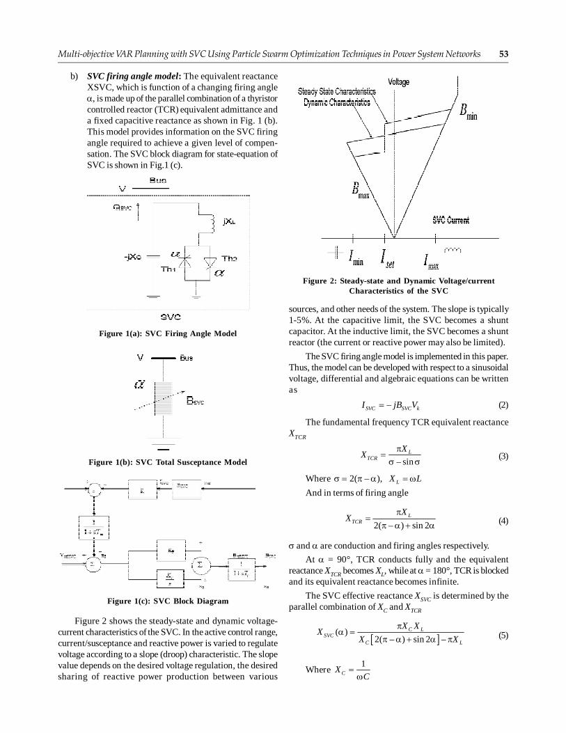
b) SVC firing angle model: The equivalent reactanceXSVC, which is function of a changing firing angle�, is made up of the parallel combination of a thyristorcontrolled reactor (TCR) equivalent admittance anda fixed capacitive reactance as shown in Fig. 1 (b).This model provides information on the SVC firingangle required to achieve a given level of compen-sation. The SVC block diagram for state-equation ofSVC is shown in Fig.1 (c).
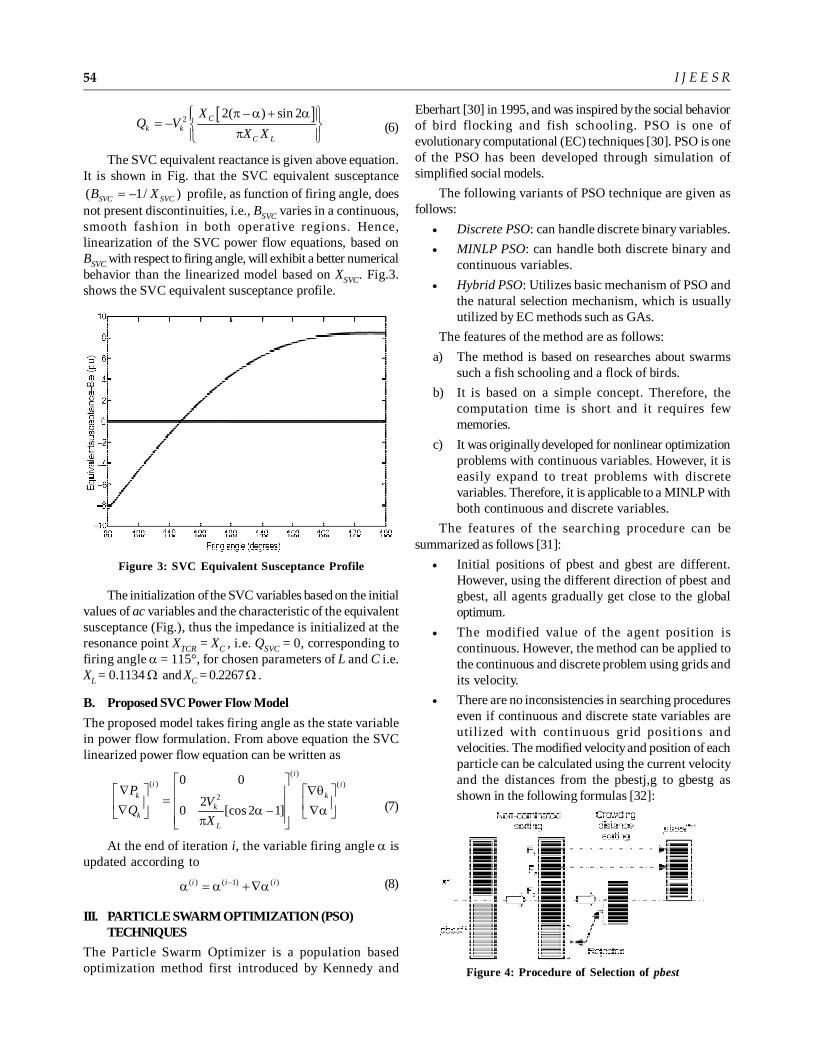
sources, and other needs of the system. The slope is typically1-5%. At the capacitive limit, the SVC becomes a shuntcapacitor. At the inductive limit, the SVC becomes a shuntreactor (the current or reactive power may also be limited).
The SVC firing angle model is implemented in this paper.Thus, the model can be developed with respect to a sinusoidalvoltage, differential and algebraic equations can be writtenas
–SVC SVC kI jB V� (2)
The fundamental frequency TCR equivalent reactanceXTCR
– sinL
TCR
XX
��� � (3)
Where 2( – ), LX L� � � � � �And in terms of firing angle
2( – ) sin 2L
TCR
XX
��� � � � (4)
� and � are conduction and firing angles respectively.
At � = 90°, TCR conducts fully and the equivalentreactance XTCR becomes XL, while at � = 180°, TCR is blockedand its equivalent reactance becomes infinite.
The SVC effective reactance XSVC is determined by theparallel combination of XC and XTCR
� �( )
2( – ) sin 2 –C L
SVCC L
X XX
X X
�� �
� � � � � (5)
Where 1
CXC
��
Figure 1(a): SVC Firing Angle Model
Figure 1(b): SVC Total Susceptance Model
Figure 1(c): SVC Block Diagram
Figure 2 shows the steady-state and dynamic voltage-current characteristics of the SVC. In the active control range,current/susceptance and reactive power is varied to regulatevoltage according to a slope (droop) characteristic. The slopevalue depends on the desired voltage regulation, the desiredsharing of reactive power production between various
Figure 2: Steady-state and Dynamic Voltage/currentCharacteristics of the SVC
54 I J E E S R
� �2 2( – ) sin 2– C
k kC L
XQ V
X X
� �� � � �� �� � ��� �� �(6)
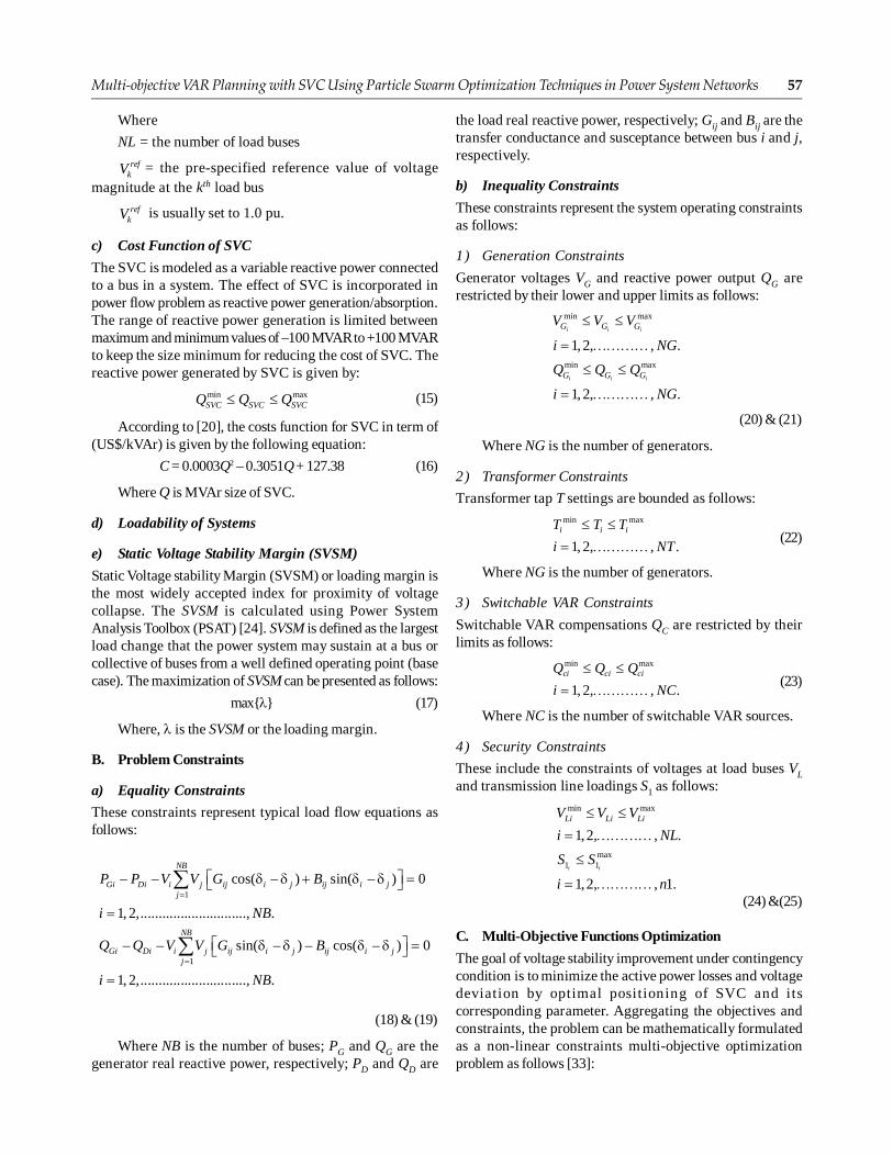
The SVC equivalent reactance is given above equation.It is shown in Fig. that the SVC equivalent susceptance( –1/ )SVC SVCB X� profile, as function of firing angle, doesnot present discontinuities, i.e., BSVC varies in a continuous,smooth fashion in both operative regions. Hence,linearization of the SVC power flow equations, based onBSVC with respect to firing angle, will exhibit a better numericalbehavior than the linearized model based on XSVC. Fig.3.shows the SVC equivalent susceptance profile.
Eberhart [30] in 1995, and was inspired by the social behaviorof bird flocking and fish schooling. PSO is one ofevolutionary computational (EC) techniques [30]. PSO is oneof the PSO has been developed through simulation ofsimplified social models.
The following variants of PSO technique are given asfollows:
� Discrete PSO: can handle discrete binary variables.
� MINLP PSO: can handle both discrete binary andcontinuous variables.
� Hybrid PSO: Utilizes basic mechanism of PSO andthe natural selection mechanism, which is usuallyutilized by EC methods such as GAs.
The features of the method are as follows:
a) The method is based on researches about swarmssuch a fish schooling and a flock of birds.
b) It is based on a simple concept. Therefore, thecomputation time is short and it requires fewmemories.
c) It was originally developed for nonlinear optimizationproblems with continuous variables. However, it iseasily expand to treat problems with discretevariables. Therefore, it is applicable to a MINLP withboth continuous and discrete variables.
The features of the searching procedure can besummarized as follows [31]:
� Initial positions of pbest and gbest are different.However, using the different direction of pbest andgbest, all agents gradually get close to the globaloptimum.
� The modified value of the agent position iscontinuous. However, the method can be applied tothe continuous and discrete problem using grids andits velocity.
� There are no inconsistencies in searching procedureseven if continuous and discrete state variables areutilized with continuous grid positions andvelocities. The modified velocity and position of eachparticle can be calculated using the current velocityand the distances from the pbestj,g to gbestg asshown in the following formulas [32]:
Figure 3: SVC Equivalent Susceptance Profile
The initialization of the SVC variables based on the initialvalues of ac variables and the characteristic of the equivalentsusceptance (Fig.), thus the impedance is initialized at theresonance point XTCR = XC , i.e. QSVC = 0, corresponding tofiring angle � = 115°, for chosen parameters of L and C i.e.XL = 0.1134 � and XC = 0.2267 � .
B. Proposed SVC Power Flow Model
The proposed model takes firing angle as the state variablein power flow formulation. From above equation the SVClinearized power flow equation can be written as
( )( ) ( )
2
0 0
20 [cos 2 –1]
ii i
k k
kk
L
PV
QX
� �� ��� � � �� ��� � � �� �� � ��� �� � � ��� �
(7)
At the end of iteration i, the variable firing angle � isupdated according to
( ) ( –1) ( )i i i� � � ��� (8)
III. PARTICLE SWARM OPTIMIZATION (PSO)TECHNIQUES
The Particle Swarm Optimizer is a population basedoptimization method first introduced by Kennedy and Figure 4: Procedure of Selection of pbest

Multi-objective VAR Planning with SVC Using Particle Swarm Optimization Techniques in Power System Networks 55
Fig.4. shows the Procedure of selection of pbest.
The concept of modification of a searching point byPSO is shown in fig.5.
Basically, the PSO was developed through simulationof birds flocking in two-dimensional space. The position ofeach bird (called agent) is represented by a point in the X-Ycoordinates, and the velocity is similarly defined. Birdflocking is assumed to optimize a certain objective function.Each agent knows its best value so far (pbest) and its currentposition. This information is an analogy of personalexperience of an agent. Morever, each agent knows the bestvalue so far in the group (gbest) among pbests of all agents.This information is an analogy of an agent knowing howother agents around it have performed. Each agent tries tomodify its position using the concept of velocity. The velocityof each agent can be updated by the following equation:
11 1
2 2
* * *( – )
* *( – )
k k ki i i i
ki
v w v c rand pbest s
c rand gbest s
� � �
�(9)
Wherekiv = the velocity of agent i at iteration k,
w = weighting function,
c1 and c2 = are weighting factors,
rand1 and rand2 = are random numbers between 0 and 1,kis = the current position of agent i at kth
iteration1k
is � = the current position of agent i at (k+1)th
iterationkiv = the velocity of agent i at kth iteration
1kiv � = the velocity of agent i at (k+1)th iteration
pbesti = the particle best of agent i
gbest = the global best of the group
The following weighting function is usually used inabove equation:
max minmax
max
––
w ww w iter
iter� � (10)
Where
wmax = the initial weight
wmin = the final weight
itermax = the maximum iteration number
iter = the current iteration number.
Using the previous equations, a certain velocity, whichgradually brings the agents close to pbest and gbest, can becalculated. The current position (search point in the solutionspace) can be modified by the following equation:
1 1k k ki i is s v� �� � (11)
The model using (9) is called gbest model. The model(10) in (9) is called inertia weights approach (IWA). Theparameters of PSO techniques are given in table 1.
Table 1Parameters of Particle Swarm Optimization Techniques
Parameters PSO
Population Size 50
Number of Particles 10
Inertia Weight (Weighing Factor), w Linearly decreased
c1 (Acceleration Constant) 1.4
c2 (Acceleration Constant) 1.4
No. of Iterations 100
rand1 0.3
rand2 0.2
wmax (Initial Weight) 1.3
wmin (Final Weight) 1.4
itermax (maximum iteration number) 50
iter (current iteration number) 20
The velocity of the particle is modified by using (9) andthe position is modified by using (11). The inertia weightfactor is modified according to (10) to enable quickconvergence. Implementation of an optimization problem ofPSO is realized within the evolutionary process of a fitnessfunction. The fitness function adopted is given as:
1fitness
objective penalty�
� (12)
where objective function is the generation cost and thepenalty is the bus voltage angle. Penalty cost has been addedto discourage solutions which violate the bindingconstraints. Finally, the penalty factor is tended to zero. ThePSO algorithm or flowchart to find the optimal location ofFACTS devices shown in Fig.6.
Figure 5: Concept of Modification of a Searching Pointby PSO

56 I J E E S R
The step by step algorithm for the proposed optimalplacement of FACTS devices is given below:
Step 1: The number of devices to be placed, type ofFACTS device to be used in the case of singletype of FACTS device and the initial load factorare declared.
Step 2: In case of multi type of FACTS devices, type ofdevice is also taken as a variable.
Step 3: The initial population of individuals is createdsatisfying the FACTS device’s constraints givenby (6) and (7) and also it is verified that only onedevice is placed in each line.
Step 4: For each individual in the population, the fitnessfunction given by (1) is evaluated after runningload flow.
Step 5: The velocity is updated by (10) and newpopulation is created by (11).
Step 6: If maximum iteration number is reached, then goto next step else go to step 4.
Step 7: If the final best individual obtained satisfies thecondition J=1, which means that the line flowand bus voltage are within their maximum andminimum limits, and then it is stored with its costof installation and settings. Increase the loadfactor and go to step 3, else go to next step.
Step 8: Print the previous best individual’s cost ofinstallation and its settings.
Step 9: Stop.
IV. PROBLEM FOMULATION
The VAr planning problem using SVC can be formulated byconsidering a number of different objective functions, i.e.,multi-objective functions. They include in this paperreduction of the active or real power loss, reduction of loadvoltage deviation, reduction of the cost function of SVC,increased the loadability of systems or static voltage stabilitymargin (SVSM).
A. Multi-objective Functions
The goal is that to find the best SVC location and the level ofcompensation, which would result in the increase of systemVAr margin. System VAr margin can be evaluated bystressing the system gradually from an initial operating stateuntil the state of critical voltage stability is reached. Thiscan be done by increasing all loads gradually close to thepoint of voltage collapse. Increasing system VAr margin couldbe achieved by placing SVC considering the followingobjective functions:
a) Active or Real Power Loss
The total power loss to be minimized is as follows:
2 2
1
– 2 cos( – )nl
Loss k i j i j i jk
P Min g V V VV�
� �� �� � � �� �� �� �� (13)
Where
nl = the number of transmission line
gk = the conductance of kth transmission line
i iV�� and j jV �� = are the voltages at the end buses i
and j of the kth transmission line, respectively.
b) Maximum Load Voltage Deviation
To have a good voltage performance (to keep the voltagebetween 0.95-1.05 per unit), the voltage deviation at eachload bus must be made as small as possible. The voltagedeviation to be minimized is as follows:
1
–NL
refk k
k
LVD Min V V�
� �� � �
� �� (14)
Figure 6: Flowchart of the PSO Algorithm
Multi-objective VAR Planning with SVC Using Particle Swarm Optimization Techniques in Power System Networks 57
Where
NL = the number of load busesref
kV = the pre-specified reference value of voltagemagnitude at the kth load bus
refkV is usually set to 1.0 pu.
c) Cost Function of SVC
The SVC is modeled as a variable reactive power connectedto a bus in a system. The effect of SVC is incorporated inpower flow problem as reactive power generation/absorption.The range of reactive power generation is limited betweenmaximum and minimum values of –100 MVAR to +100 MVARto keep the size minimum for reducing the cost of SVC. Thereactive power generated by SVC is given by:
min maxSVC SVC SVCQ Q Q� � (15)
According to [20], the costs function for SVC in term of(US$/kVAr) is given by the following equation:
C = 0.0003Q2 – 0.3051Q + 127.38 (16)
Where Q is MVAr size of SVC.
d) Loadability of Systems
e) Static Voltage Stability Margin (SVSM)
Static Voltage stability Margin (SVSM) or loading margin isthe most widely accepted index for proximity of voltagecollapse. The SVSM is calculated using Power SystemAnalysis Toolbox (PSAT) [24]. SVSM is defined as the largestload change that the power system may sustain at a bus orcollective of buses from a well defined operating point (basecase). The maximization of SVSM can be presented as follows:
max{�} (17)
Where, � is the SVSM or the loading margin.
B. Problem Constraints
a) Equality Constraints
These constraints represent typical load flow equations asfollows:
1
1
– – cos( – ) sin( – ) 0
1, 2,............................., .
– – sin( – ) – cos( – ) 0
1, 2,............................., .
NB
Gi Di i j ij i j ij i jj
NB
Gi Di i j ij i j ij i jj
P P V V G B
i NB
Q Q V V G B
i NB
�
�
� �� � � � � �� �
�
� �� � � � �� �
�
�
�
(18) & (19)
Where NB is the number of buses; PG and QG are thegenerator real reactive power, respectively; PD and QD are
the load real reactive power, respectively; Gij and Bij are thetransfer conductance and susceptance between bus i and j,respectively.
b) Inequality Constraints
These constraints represent the system operating constraintsas follows:
1) Generation Constraints
Generator voltages VG and reactive power output QG arerestricted by their lower and upper limits as follows:
min max
min max
1, 2, , .
1, 2, , .
i i i
i i i
G G G
G G G
V V V
i NG
Q Q Q
i NG
� �
� ����
� �
� ����
(20) & (21)
Where NG is the number of generators.
2) Transformer Constraints
Transformer tap T settings are bounded as follows:min max
1, 2, , .i i iT T T
i NT
� �� ����
(22)
Where NG is the number of generators.
3) Switchable VAR Constraints
Switchable VAR compensations QC are restricted by theirlimits as follows:
min max
1, 2, , .ci ci ciQ Q Q
i NC
� �� ����
(23)
Where NC is the number of switchable VAR sources.
4) Security Constraints
These include the constraints of voltages at load buses VLand transmission line loadings S1 as follows:
min max
max1 1
1,2, , .
1,2, , 1.i i
Li Li LiV V V
i NL
S S
i n
� �
� ����
�
� ����(24) &(25)
C. Multi-Objective Functions Optimization
The goal of voltage stability improvement under contingencycondition is to minimize the active power losses and voltagedeviation by optimal positioning of SVC and itscorresponding parameter. Aggregating the objectives andconstraints, the problem can be mathematically formulatedas a non-linear constraints multi-objective optimizationproblem as follows [33]:

58 I J E E S R
� �( , ), ( , )LMinimize P x u VD x u
Subjected to:
g(x,u) = 0
h(x,u) � 0
Where x is the vector of dependent variables consistingof load bus voltages VL, generator reactive power outputsQG, and transmission line loadings S1. Hence, x can beexpressed as follows:
1 1 11 1, , ; , , ; ,NL NG nl
TL L G Gx V V Q Q S S� �� � � �� �
The u is the vector of control variable consisting ofgenerator voltages VG, transmission tap settings T, and shuntVAR compensations QC. Hence, u can be expressed asfollows:
1 11, , ; , , ; ,NG NC
TG G NT c cu V V T T Q Q� �� � � �� �
g is the equality constraints.
h is the inequality constraints.
Hence, the multi-objective function also can be expressedas follows:
1 2 3 4min Lossf P LVD C L SVSM� �� � � � � � �
Where2 2 – 2 cos( – ) cosL i j i j i j ij ijP V V VV Y� �� � � � �� ��
max
–k ref kVD k V V� � �
C = 0.0003Q2 – 0.3051Q + 127.38
L = 0.0003Q2 – 0.3051Q + 127.38
SVSM = 0.0003Q2 – 0.3051Q + 127.38
1 2 3 4, , ,� � � � � Penalty factors to give equal weightagefor losses voltage deviation, cost of SVC, and Loadability ofsystem.
Subjected to
Equality constraints
1
– – cos( – ) 0BN
Gi Di i j ij ij j ij
P P VV Y�
� � � � ��
1
– – sin( – ) 0BN
Gi Di i j ij ij j ij
Q Q VV Y�
� � � � ��
Inequality constraintsmin maxsh sh shQ Q Q� �
min maxi i iV V V� �
There are a number of approaches to solve the multi-objective optimization problem. Since SVC placementaccording to the multi-objective functions is difficult withan analytical method, a PSO technique is proposed in thispaper to achieve a tradeoff between the objective functions.
V. CONCLUSIONS
In this paper presents the optimal placement techniques forSVC form different performance parameter of systemsviewpoints such as improve the voltage profile, reduce activepower losses, reduce the voltage deviation and cost ofsystems, increase the loadability of systems. The proposedtechnique also applicable for optimal placement of otherFACTS controllers such as TCSC, SSSC, STATCOM, UPFC,GUPFC, IPFC in similar fashion.
ACKNOWLEDGMENT
The authors would like to thanks Dr. S. C. Srivastava, and Dr.S. N. Singh, Indian Institute of Technology, Kanpur, U.P.,India, for their valuables suggestions regarding optimalplacement techniques for FACTS controllers form differentperformance parameter of systems viewpoints such asimprove the voltage profile, reduce active power losses,reduce the voltage deviation and cost of systems, increasethe loadability of systems.
References[1] P. Kundur, “Power System Stability and Control”, Mc Graw-
Hill: New York, 1994.
[2] K. Y.Lee and M. A. El-Sharkawi (Editors), “Tutorial onModern Heuristic Optimization Techniques with Applicationsto Power Systems IEEE Power Engineering Society”, IEEECatalog Number 02TP160, Piscataway, NJ, 2002.
[3] K. Y.Lee and M. A. El-Sharkawi (Editors), “A Tutorial Courseon Evolutionary Computation Techniques for Power SystemOptimization”, IFAC Symposium on Power Plants and PowerSystem Control, Seoul, Korea, 2003.
[4] K. Y. Lee (Editor), “Tutorial on Intelligent Optimization andControl of Power Systems”, The 13th International Conferenceon Intelligent Systems Application to Power Systems, Arlington,VA, 2005.
[5] J. G. Vlachogiannis, N. D. Hatziargyriou, and K.Y. Lee, “AntColony System Based Algorithm for Constrained Load FlowProblem”, IEEE Trans. Power Syst., 20, No. 3, pp. 1241-1249,August 2005.
[6] S. Gerbex, R. Cherkaoui and A.J. Germond, “Optimal Locationof Multitype FACTS Devices in a Power System by Meansof Genetic Algorithms”, IEEE Trans. Power Syst., 16, No. 3,pp. 537-544, August 2001.
[7] K. Y. Lee, X. Bai, and Y. M. Park, “Optimization Method forReactive Power Planning Using a Genetic Algorithm”, IEEETrans. Power Syst., 10, No. 4, pp. 1843-1850, November1995.
[8] Kundur P., “Inter-area Oscillations in Power System”, IEEEPower Engineering Society, pp. 13-16, October 1994.
[9] A. Kazemi, and B. Badrzadeh, “Modeling and Simulation ofSVC and TCSC to Study Their Limits on MaximumLoadalibility Point”, Electrical Power & Energy Systems, 26,pp. 619-626, 2004.
[10] Claudio A. Canizares, and Zeno T. Faur, “Analysis of SVCand TCSC Controllers in Voltage Collapse”, IEEE Trans onPower Systems, 14, No. 1, February 1999.

Multi-objective VAR Planning with SVC Using Particle Swarm Optimization Techniques in Power System Networks 59
[11] Y. Mansour, W. Xu. F. Alvarado, and C. Rinzin, “SVCPlacement Using Critical Modes of Voltage Stability”, IEEETrans. on Power Systems, 9, pp. 757-762, May 1994.
[12] Cigre Working Group, “Modeling of Static VAR Systems forSystems Analysis”, Electra, 51, pp. 45-74, 1977.
[13] Malihe M. Farsangi, Hossein Mezamabadi-pour, “Placementof SVCs and Selection of Stabilizing Signals in PowerSystems”, IEEE Trans. on Power Systems, 22, No. 3, August2007.
[14] N. K. Sharma, A. Ghosh, and R. K. Verma, “A Novel PlacementStrategy for FACTS Controllers”, IEEE Trans. on PowerDelivery, 18, No.3, July 2003.
[15] N. Martins and L.T.G. Lima, “Determination of SuitableLocations for Power System Stabilizers and Static VarCompensators for Damping Electro-mechanical Oscillationin large Scale Power Systems”, IEEE Trans. on Power Systems,5, No.4, pp. 1455-1469, November 1990.
[16] M. K. Verma, and S. C. Srivastava, “Optimal Placement ofSVC for Static and Dynamic Voltage Security Enhancement”,International Journal of Emerging Electric Power Systems, 2,Issue-2, 2005.
[17] Narain G. Hingorani, L. Gyugyi, “Understanding FACTS:Concepts and Technology of Flexible AC TransmissionSystems”, IEEE Press, 2000, ISBN0-7803-345508.
[18] C.J. Parker I.F. Morrison, D. Sutanto, “Application of anOptimisation Method for Determining the Reactive Marginfrom Voltage Collapse in Reactive Power Planning”, IEEETransactions on Power Systems, 11, No. 3, August 1996 1473.
[19] Yakout Mansour Wilsun Xu Fernando Alvarado ChhewangRinzin B.C., “SVC Placement Using Critical Modes of VoltageInstability”, IEEE Transactions on Power Systems, 9, No. 2.May 1994, pp. 757-764.
[20] M.M. Farsangi, H. Nezamabadi-Pour and K. Y. Lee,“Multiobjective VAr Planning with SVC for a Large PowerSystem Using PSO and GA”, Proc. 2006 IEEE PES PowerSystems Conference and Exposition (PSCE), Atlanta, USA,29Oct-1Nov, 2006.
[21] J.G. Singh, S. N. Singh, and S. C. Srivastava, “Placement ofFACTS Controllers for Enhancing Power SystemLoadability”, IEEE Trans. on Power Delivery, 12, No.3, July2006.
[22] R.K. Verma, “Control of Static VAR Systems for Improvementof Dynamic Stability and Damping of Torsional Oscillations”,Ph.D. Thesis, IIT Kanpur, April 1998.
[23] Roberto Mingues, Federico Milano, Rafael Zarate-Minano,and Antonio J. Conejo, “Optimal Network Placement of SVCDevices”, IEEE Trans. on Power Systems, 22, No.4, November2007.
[24] C. S. Chang, and J. S. Huang, “Optimal SVC Placement forVoltage Stability Reinforcements”, Electric Power SystemResearch, 42, pp.165-172, 1997.
[25] R. M. Hamouda, M. R. Iravani, and R. Hacham, “CoordinatedStatic VAR Compensators for Damping Power SystemOscillations”, IEEE Trans. on Power Systems, PWRS-2, No.4,November 1987.
[26] Yuan-Lin Chen, “Weak Bus-Oriented Optimal Multi-Objective VAR Planning”, IEEE Trans on Power Systems, 11,No.4, November 1996.
[27] Ying-Yi Hong, and Chen-Ching Liu, “A Heuristic andAlgorithmic Approach to VAR Planning”, IEEE Trans. onPower Systems, 7, No.2, May 1992.
[28] Y. Chang, “Design of HVDC and SVC Coordinate DampingController Based on Wide Area Signal”, International Journalof Emerging Electric Power Systems, 7, Issue 4, 2006.
[29] C. P. Gupta, “Voltage Stability Margin Enhancement usingFACTS Controllers”, Ph.D. Thesis, IIT Kanpur, October,2000.
[30] J. Kennedy, and R. Eberhart, “Particle Swarm Optimization”,in Proc. 1995 IEEE Int. Conf. Neural Networks (ICNN’95),IV, pp. 1942-1948, 1995.
[31] Sidhartha Panda, Narayana Prasad Padhy, “Comparison ofParticle Swarm Optimization and Genetic Algorithm forFACTS-based Controller Design, “Applied Soft Computing,8 (2008), 1418-1427.
[32] Z.L. Gaing, “A Particle Swarm Optimization Approach forOptimum Design of PID Controller in AVR System”, IEEETrans. Energy Conv., 9(2), (2004), 84-391.
[33] M. A. Abido, and J. M. Bakhashwain, “Optimal VAR DispatchUsing a Multi-objective Evolutionary Algorithm”, ElectricalPower & Energy Systems, 27, 2005, pp.13-20.