Multi-Loop Systems, 4 Closed-Loop Drainback Systems · Drainback systems include a separate tank...
21
© Festo Didactic 52669-20 41 Drainback systems can consist of two closed-loop circuits. Each loop contains an active pump to circulate the solar and storage fluids independently. These systems can be used for heating water and space (air and/or surfaces). When solar energy is available, the contents of a small storage tank, called a drainback tank are heated by the primary system loop. When the tank reaches the differential controller’s temperature setting, the circulator pump is turned off, and the water in the solar collector array drains backwards through the system into the drainback tank. For this reason, a check valve should not be installed in a drainback system loop. The system is simplified further by its low-pressure operation. An external heat exchanger (or an integrated one inside the tank), extracts heat from the drainback tank, as a secondary system loop pumps the heated fluid into a solar storage tank or a space heating element, such as a hydronic radiator or radiant flooring. The drainback tank must be installed below the collector and plumbing must be angled downward from the top of the collector to let gravity drain the fluid without any pump assistance. The pipes must also be well supported to minimize any sagging. A vacuum breaker valve must be installed at the top outlet of the solar collector to automatically permit air to enter the collector panel as it drains. This action prevents any potentially high vacuum from collapsing the collector panel, and also allows the collector to empty its contents completely. A high-head pump is often required to push the solar fluid upwards, back to the top of the collector, whenever the system turns on. Certain solar collectors cannot be used with drainback systems, such as flat- plate collectors with serpentine riser tubes and some evacuated-tube collectors. Drainback tanks Drainback systems include a separate tank (in addition to a storage tank), called a drainback tank. As shown in Figure 18, this tank is often smaller and is specifically intended to store the drained fluid from the solar collector array. Closed-Loop Drainback Systems Information Job Sheet 4
Transcript of Multi-Loop Systems, 4 Closed-Loop Drainback Systems · Drainback systems include a separate tank...

© Festo Didactic 52669-20 41
Drainback systems can consist of two closed-loop circuits. Each loop contains an active pump to circulate the solar and storage fluids independently. These systems can be used for heating water and space (air and/or surfaces).
When solar energy is available, the contents of a small storage tank, called a drainback tank are heated by the primary system loop. When the tank reaches the differential controller’s temperature setting, the circulator pump is turned off, and the water in the solar collector array drains backwards through the system into the drainback tank. For this reason, a check valve should not be installed in a drainback system loop. The system is simplified further by its low-pressure operation. An external heat exchanger (or an integrated one inside the tank), extracts heat from the drainback tank, as a secondary system loop pumps the heated fluid into a solar storage tank or a space heating element, such as a hydronic radiator or radiant flooring. The drainback tank must be installed below the collector and plumbing must be angled downward from the top of the collector to let gravity drain the fluid without any pump assistance. The pipes must also be well supported to minimize any sagging. A vacuum breaker valve must be installed at the top outlet of the solar collector to automatically permit air to enter the collector panel as it drains. This action prevents any potentially high vacuum from collapsing the collector panel, and also allows the collector to empty its contents completely. A high-head pump is often required to push the solar fluid upwards, back to the top of the collector, whenever the system turns on. Certain solar collectors cannot be used with drainback systems, such as flat-plate collectors with serpentine riser tubes and some evacuated-tube collectors.
Drainback tanks
Drainback systems include a separate tank (in addition to a storage tank), called a drainback tank. As shown in Figure 18, this tank is often smaller and is specifically intended to store the drained fluid from the solar collector array.
Closed-Loop Drainback Systems
Information Job Sheet 4
Job Sheet 4 – Closed-Loop Drainback Systems
42 © Festo Didactic 52669-20
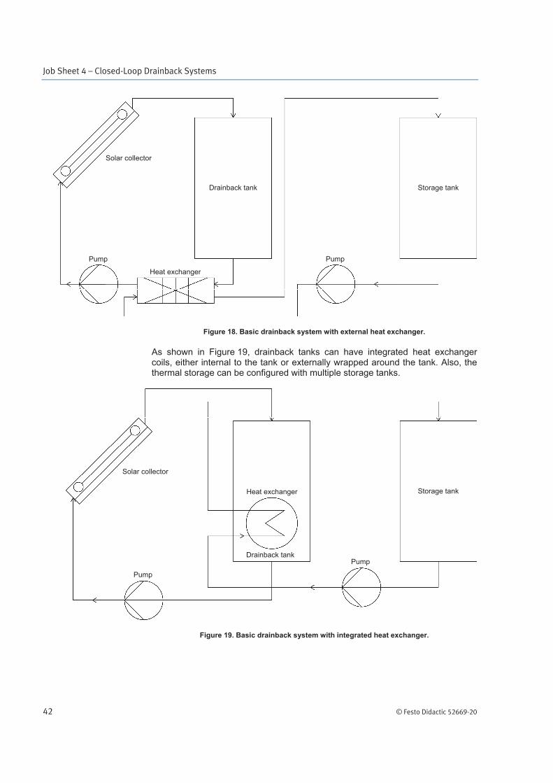
Figure 18. Basic drainback system with external heat exchanger.
As shown in Figure 19, drainback tanks can have integrated heat exchanger coils, either internal to the tank or externally wrapped around the tank. Also, the thermal storage can be configured with multiple storage tanks.
Figure 19. Basic drainback system with integrated heat exchanger.
Drainback tank Storage tank
Pump
Heat exchanger
Pump
Solar collector
Drainback tank
Storage tank
Pump
Heat exchanger
Pump
Solar collector

Job Sheet 4 – Closed-Loop Drainback Systems
© Festo Didactic 52669-20 43
The drainback tank is a thermally insulated, unvented vessel that often contains a sight glass (sight gauge) to visually monitor the fluid level within the tank. When commissioning a drainback system, the drainback tank must only be filled partially, well below the tank’s maximum capacity. Sizing the tank requires a simple determination of liquid volume within the solar collector array, including all piping that exists above the drainback tank level. Then, add 15.14 L for extra margin. Another rule-of-thumb is to simply double the solar fluid loop volume. Common tank sizes range from 18.93 to 113.56 L in 18.93 L increments. Standard electric water heaters range in size from 113.56 to 454.25 L, and may be used as large drainback tanks. Larger custom tanks are also available from 378.54 to 7 570.82 L. A pressure relief valve is often installed on the drainback tank, and is usually set for 344.74 kPa.
In the solar thermal training system, the storage tank is used as the drainback tank and a secondary storage tank is assumed.
Drainback pumps
Pump selection is critical for a drainback system to function properly. AC-powered, high-head, low-flow pumps are required to move the solar fluid back up to the solar collectors from the bottom of the drainback tank. The head for the pump is determined by adding four feet to the vertical distance between the bottom of the drainback tank and the uppermost part of the solar collector array. The extra margin helps to ensure that friction head is overcome.
System performance
This job sheet involves installing and operating a dual closed-loop water (DHW) and space (floor or air) drainback system with thermal storage, which has the following advantages and disadvantages.
System type
Active, indirect, closed-loop, unvented, water (DHW) and space (floor or
air) heating with storage.
Advantages
Efficient operation
Simple configuration reduces cost and lowers maintenance
Overheat-protection turns off pump when high temperature is reached
Can use water or sand for thermal storage
Limited freeze-protection provided without antifreeze
If used, antifreeze life is extended (compared to pressurized systems)

Job Sheet 4 – Closed-Loop Drainback Systems
44 © Festo Didactic 52669-20
Disadvantages
Can freeze over extended cold periods, not for extremely cold climates
Additional tank or special tank needed
High-head pump needed
Collector array must be placed near and above storage tank
Drainback tank must be placed below collector array and above storage
tank
Only certain solar collectors that drain properly can be used
Collector piping must be sloped at least 1°, and cannot sag
Careful planning and installation is needed
© Festo Didactic 52669-20 45
In this job sheet, you will install a dual closed-loop water (DHW) and space (floor or air) drainback system that includes thermal storage and can use antifreeze as part of a solar thermal energy system. Four different solar heating systems can be installed. Three of these drainback systems use internal heat exchangers that are an integral part of the drainback tank: one for heating water, one for heating water and flooring, or one for heating water and space. A fourth example of a drainback system uses an external heat exchanger to heat water.
Equipment required
Refer to the Equipment Utilization Chart in Appendix A to obtain the list of equipment required for this job sheet.
Safety procedures
Before proceeding with this job sheet, complete the following checklist.
You are wearing safety glasses.
You are wearing safety shoes.
You are not wearing anything that might get caught such as a tie, jewelry, or loose clothes.
If your hair is long, tie it out of the way.
The working area is clean and free of oil.
The floor is not wet.
Your sleeves are rolled up.
The wheels of the system are locked in place.
Closed-Loop Drainback Systems
Job Sheet 4
OBJECTIVE
PROCEDURE

Job Sheet 4 – Closed-Loop Drainback Systems
46 © Festo Didactic 52669-20
Installation
1. Figure 20 through Figure 23 show indirect solar heating systems with thermal storage for heating water and/or air. Choose one of those systems, then continue this procedure using the selected system.
Figure 20. Closed-loop, water-heating drainback (storage) system schematic.
Vacuum breaker
Expansion tank
Pressure-relief valve
TST
Heat exchangers
Storage tank
Ball valve
Funnel
Fill bowl
Shutoff valve
Ball valve
Solar collector
COL
TRF
Differential controller
Shutoffvalve
Storage tank
Pump
Pump
Ball valve
Hot water outlet(DHW to taps)
Cold waterinlet (WS)
Job Sheet 4 – Closed-Loop Drainback Systems
© Festo Didactic 52669-20 47
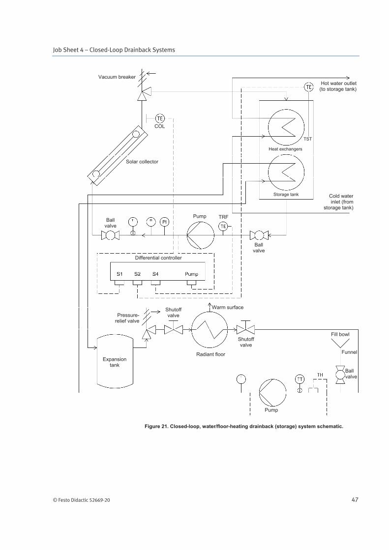
Figure 21. Closed-loop, water/floor-heating drainback (storage) system schematic.
Vacuum breaker
Expansion tank
Pressure-relief valve
TST
Heat exchangers
Storage tank
Ball valve
Funnel
Fill bowl Shutoff valve
Ball valve
Solar collector
COL
TRF
Differential controller
Shutoff valve
Pump
Pump
Ball valve
Hot water outlet (to storage tank)
Cold water inlet (from
storage tank)
Radiant floor
Warm surface

Job Sheet 4 – Closed-Loop Drainback Systems
48 © Festo Didactic 52669-20
Figure 22. Closed-loop, water/air-heating drainback (storage) system schematic.
Vacuum breaker
Expansion tank
Pressure-relief valve
TST
Heat exchangers
Storage tank
Ball valve
Funnel
Fill bowl
Ball valve
Solar collector
COL
TRF
Differential controller
Pump
Pump
Ball valve
Hot water outlet(to storage tank)
Cold waterinlet (from
storage tank)
Shutoff valve
Radiator
Warm air outlet
Fan
Cold airinlet (AS)
Power input (ES)
Shutoff valve
Job Sheet 4 – Closed-Loop Drainback Systems
© Festo Didactic 52669-20 49
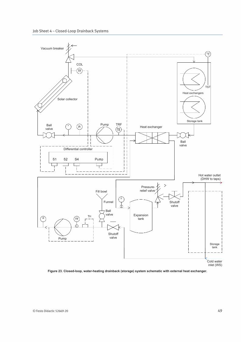
Figure 23. Closed-loop, water-heating drainback (storage) system schematic with external heat exchanger.
Vacuum breaker
Expansion tank
Pressure-relief valve
TST
Heat exchangers
Storage tank
Ball valve
Funnel
Fill bowl
Ball valve
Solar collector
COL
TRF
Differential controller
Pump
Pump
Ball valve
Hot water outlet(DHW to taps)
Cold waterinlet (WS)
Shutoff valve
Shutoff valve
Heat exchanger
Storage tank

Job Sheet 4 – Closed-Loop Drainback Systems
50 © Festo Didactic 52669-20
2. Ensure that the following parts are mounted on the mobile workstation as shown in Figure 24 to Figure 27.
Solar collector
Circulator pumps (2)
Storage tank (used as drainback tank)
Plate heat exchanger
Differential controller (with 3 sensors)
Thermostat controller (with 1 sensor)
Expansion tank (1)
Radiator
Radiant floor
Thermometers (2)
Rotameters (2)
Pressure gauge
Pressure relief valve (1)
Vacuum breaker valve
Shutoff valves (2)
Fill bowl (1)
Electrical panel

Job Sheet 4 – Closed-Loop Drainback Systems
© Festo Didactic 52669-20 51
Figure 24. Closed-loop, water-heating drainback (storage) system configuration.
Primary loop
Secondary loop
Hot flow
Cold return
Warm path
Hot flow
Cold return
Warm path

Job Sheet 4 – Closed-Loop Drainback Systems
52 © Festo Didactic 52669-20
Figure 25. Closed-loop, water/floor-heating drainback (storage) system configuration.
Primary loop
Secondary loop
Hot flow
Cold return
Warm path
Hot flow
Cold return
Warm path

Job Sheet 4 – Closed-Loop Drainback Systems
© Festo Didactic 52669-20 53
Figure 26. Closed-loop, water/air-heating drainback (storage) system configuration.
Primary loop
Secondary loop
Hot flow
Cold return
Warm path
Hot flow
Cold return
Warm path
Job Sheet 4 – Closed-Loop Drainback Systems
54 © Festo Didactic 52669-20
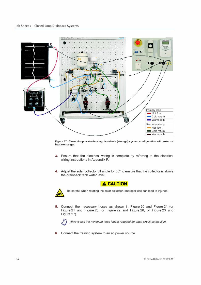
Figure 27. Closed-loop, water-heating drainback (storage) system configuration with external heat exchanger.
3. Ensure that the electrical wiring is complete by referring to the electrical wiring instructions in Appendix F.
4. Adjust the solar collector tilt angle for 50° to ensure that the collector is above the drainback tank water level.
Be careful when rotating the solar collector. Improper use can lead to injuries.
5. Connect the necessary hoses as shown in Figure 20 and Figure 24 (or Figure 21 and Figure 25, or Figure 22 and Figure 26, or Figure 23 and Figure 27).
a Always use the minimum hose length required for each circuit connection.
6. Connect the training system to an ac power source.
Primary loop
Secondary loop
Hot flow
Cold return
Warm path
Hot flow
Cold return
Warm path
Job Sheet 4 – Closed-Loop Drainback Systems
© Festo Didactic 52669-20 55
7. Partially fill the system with water by performing the System filling procedure in Appendix C, while adhering to the following note:
a Do not fill the drainback tank completely. Fill the tank to a depth of about 22.2 cm (measured at tank center).
Be careful to prevent water from being in contact with electrical components. Use
a bucket and mop if some leakage occurs.
8. Turn the power on by setting the circuit breaker to I.
9. Start the pumps by setting both override switches to Override.
Then, set the pumps to III.
10. Evacuate the air present in the system using the priming procedure (refer to Appendix C).
Commissioning
11. Set the valves as shown in Table 7.
Table 7. State of the different valves.
Valves States
Fill bowl ball valve closed
Solar collector ball valve open
Storage tank ball valve open
Shutoff valves (2) open
a Make sure the solar collector outlet hose (91.44 cm long) is connected directly to the top (return port) of the drainback tank, with no sagging. Also, ensure that the vacuum breaker valve is installed.
12. Turn the pumps on by setting both override switches to the Controller position.
13. If installed, turn on the radiator and set the fan to minimum speed (Switch settings: S1 = 2, S2 = ).

Job Sheet 4 – Closed-Loop Drainback Systems
56 © Festo Didactic 52669-20
14. Use the differential controller (TDIC) to set the pump to AUTO mode. To do so, press and hold the + (right) button on the controller until a new menu appears. Then, use the + button to select the MAN-1 menu. Press the OK (center) button and use the + and - buttons to select the AUTO mode. Press the OK (center) button to confirm.
15. Use the thermostat controller (TH) to adjust the set-point temperature between 3°C to 6°C above the ambient temperature by using a rotating knob.
Ambient temperature °C
Set-point temperature °C
16. Measure (with the pump on) the different parameters listed in Table 8, then record the values in the “Initial” column of the table. After that, position and power up the two 500 W work lights so that most of the radiant energy floods the solar collector panel evenly.
a The pressure gauge port must be vertically level with the rotameter pressure port.
a If the rotameter does not indicate any flow, it means that the controller has turned the pump off.
a Use the magnetic surface thermometer to measure ambient air temperature in front of the radiator output.
The solar thermal training system should be operated under supervision at all
times. Never let the system operate unattended.
The surface of the work lights can become very hot. Whenever you manipulate
them, take great care to avoid direct contact with the skin.

Job Sheet 4 – Closed-Loop Drainback Systems
© Festo Didactic 52669-20 57
Table 8. Test results.
Device Values for different measuring times
Units Initial At 15 min At 30 min
F1-1 (flow rate) L/min
PI-1 (pressure) kPa
F1-2 (flow rate) L/min
PI-2 (Pressure) kPa
TI (collector input) °C
TI (collector output) °C
TE-S1 (COIL) °C
TE-S2 (TST) °C
TE-S4 (TRF) °C
Floor temperature °C
Air temperature °C
17. After about 15 minutes, measure (with the pump on) the different parameters listed in Table 8, then record the values in the “At 15 min” column of the table.
18. After about 30 minutes, measure (with the pump on) the different parameters listed in Table 8, then record the values in the “At 30 min” column of the table.
19. Use the differential controller override switch to turn the primary pump off.
20. Use the thermostat controller override switch to turn the secondary pump off.
21. Turn off the work lights.

Job Sheet 4 – Closed-Loop Drainback Systems
58 © Festo Didactic 52669-20
22. Measure and record the water levels in the storage tank (being used as a drainback tank) with the primary pump turned on and turned off. Measure the water depth at the tank center. See Figure 28.
a Wait at least 30 seconds with the pump off while draining ends.
Pump on: cm
Pump off: cm
Figure 28. Drainback (storage) tank water level.
23. Turn off the system and the radiator by setting the circuit breaker to O.
24. Disconnect the power cords and drain the system by performing the System draining procedure in Appendix C.

Job Sheet 4 – Closed-Loop Drainback Systems
© Festo Didactic 52669-20 59
25. Use the data in Table 9 to determine the total volume of water that is contained in the solar collector and all tubing that is situated above the drainback tank water level. Do not include the volume listed for the storage tank.
Table 9. System component volume.
Item Description Volume
(L)
87042-10 1.82 m long hose with 1.27 cm inner diameter 0.23
87042-11 91.44 cm long hose with 1.27 cm inner diameter 0.12
87042-12 60.96 cm long hose with 1.27 cm inner diameter 0.08
87042-13 30.48 cm long hose with 1.27 cm inner diameter 0.04
89515 Solar collector 0.6
46508-1C Circulator pump 0.20
87318-10 Storage tank 51.1 L (37.85 L max.) 37.85
87318-10 Coil heat exchanger 0.30
46505 Plate heat exchanger 0.11 L (x2) 0.11
46509 Temperature sensor (RTD) 0.03
52181 Thermostat controller (sensor) 0.05
46510-10 Expansion tank 7.95 L (4.16 L max.) 0.05
6531-C0 Radiator 0.26
46512 Radiant floor 0.16
46501 Thermometer 0.04
6550-A0 Rotameter 0.09
6553-E0 Pressure gauge (60.96 cm long hose with 0.46 cm inner diameter)
0.01
46503 or 46504
Pressure relief valve 0.06
6520-A0 Shutoff valve 0.04
46507 Check valve assembly 0.12
46519-10 Fill bowl 0.05
46511 Automatic air vent 0.05
a The thermostat controller (52181) is part of the workstation (46500-2C).
a Each system component volume (in liters) includes the connection ports.

Job Sheet 4 – Closed-Loop Drainback Systems
60 © Festo Didactic 52669-20
26. Based upon the estimation, how much water should drain into the drainback tank?
L
27. Calculate and record the difference in water levels ( height in cm) that you measured in the drainback tank with the primary pump turned on and turned off.
cm
28. Calculate the volumetric difference ( volume in L) between the two drainback tank conditions using the equation below.
b Use the inside dimensions of the drainback tank, or approximately 50.8 cm x 31.12 cm.
lcm
HeightWidthLengthVolume
/10003
29. Based upon the results, how much water is draining from the solar collector into the drainback tank?
L
30. Is this observed value similar to the estimated value (within 10%)?
Yes No
31. Ask the instructor to check your work.
1. Did the system work correctly?
Yes No
2. Describe and briefly explain the system behavior.
PROCEDURE QUESTIONS
Job Sheet 4 – Closed-Loop Drainback Systems
© Festo Didactic 52669-20 61
3. Name at least two locations or devices in the system where thermal energy was transferred through a containment wall.
4. Where might a similar system prove to be effective or useful?
5. Was the drainback tank water level lower when the primary pump was running (on)?
Yes No
6. Based upon the measured values, what was the overall temperature rise of the water?
7. Based upon the measured values, what was the overall temperature rise of the floor or air?
Name: ______________________________ Date: ____________________
Instructor's approval: ______________________________________________