Multi-level Modified Finite Radon Transform Network for ...
11
Multi-level Modified Finite Radon Transform Network for Image Upsampling Yang Zhao, Ronggang Wang, Member, IEEE, Wenmin Wang, and Wen Gao, Fellow, IEEE Abstract—Local line-like feature is the most important dis- criminate information in image upsampling scenario. In recent example-based upsampling methods, grayscale and gradient features are often adopted to describe the local patches, but these simple features cannot accurately characterize complex patches. In this paper, we present a feature representation of local edges by means of a multi-level filtering network, namely multi-level modified finite Radon transform network (MMFRTN). In the proposed MMFRTN, the modified finite Radon transform (MFRT) is utilized in the filtering layer to extract the local line- like feature; the nonlinear layer is set to be a simple local binary process; for the feature pooling layer, we concatenate the mapped patches as the feature of local patch. Then we propose a new example-based upsampling method by means of the MMFRTN feature. Experimental results demonstrate the effectiveness of the proposed method over some state-of-the-art methods. Index Terms—image upsampling, super-resolution, PCANet I. I NTRODUCTION I MAGE upsampling, also known as single-image super- resolution or image upscaling, is a fundamental task for var- ious computer vision and image processing applications, such as image editing, UHDTV/HDTV, medical image processing, and object recognition. In many scenarios, only low-resolution image (LRI) is available. Hence, recovering a high-resolution image (HRI) from LRI is immensely demanded. Traditional interpolation-based upsampling methods [1], [2] often produce some unnatural artifacts, e.g., blurring, jaggy, and ringing effects. To suppress these artifacts, many methods have been proposed in recent years. In general, these methods can be summarized into two categories: edge-directed methods and example-based methods. It is known that edges are more obvious than other areas for image perception [3], edge-directed methods aim to recover sharp and natural edges by enforcing some edge knowledge or extra constraints, such as smooth edge [4], geometric regularity [5], gradient prior [6]-[8], [46], local structure constraint [32], and different interpolated grids [9]-[12]. There were also some edge-enhancing algorithms that sharpen edges via different treatments, e.g., contrast enhancement [13], de-blurring and de-convolution [14], [33], and edge energy term constraint [15]. This work was partly supported by the grant of National Science Foundation of China 61370115, 61402018, 61305006, 61175022, China 863 project of 2015AA015905, the grant of China Postdoctoral Science Foundation, No. 2014M550016, Shenzhen Fundamental Research Project, and Shenzhen Peacock Plan. The authors are with the School of Electronic and Computer Engineering, Peking University Shenzhen Graduate School, 2199 Lishui Road, Shenzhen 518055, China (e-mail: [email protected]; [email protected]; [email protected]; [email protected]). Example-based methods often utilize high-resolution (HR) samples to get the co-occurrence prior between HR and low- resolution (LR) image patches. This type of method was first proposed in [16] and was further developed in [17]-[21], and [36]-[45]. Chang et al. [36] proposed a super-resolution method based on neighbor embedding and the manifold learn- ing method locally linear embedding (LLE). In [17], Yang et al. proposed an effective learning method based on sparse representation and achieved impressive results. Many sparse representation based methods were then proposed, such as bilevel dictionary learning [18], beta process joint dictionary learning [40], statistical prediction model based method [41], non-locally centralized sparse representation [42], and sub- dictionaries method [19]. In [20] and [21], single-image local self-example-based methods were introduced by considering the similarities of local patches in different scales of the same image. Recently, Turkan et al. [38], [39] presented super- resolution methods by means of neighbor embedding and single-image local-self-exemplar. In example-based upsampling scenario, the feature of LR patch is utilized as ”index” to search corresponding exemplars from the dictionary. Extracting accurate local feature is thus very important for image upsampling. However, most recent example-based methods merely utilize simple features, such as mean-value-removed grayscale, contrast-normalized grayscale [16], first- and second-order derivative [36], [17]-[19], [40]- [42], and applying PCA dimensionality reduction to the first- and second-order derivative [43], [45]. These simple features cannot well characterize complex local edges due to their limited discriminative capability. Therefore example-based methods with these simple features may produce unnatural artifacts around some complex edges such as zigzag edges and coastline-like edges. Is there better feature representation of local patch for image upsampling? This is the main issue to be addressed in this paper. Numerous algorithms have been proposed to extract local features, such as LBP [22], SIFT [23], and HOG [24]. Re- cently, deep networks model drew significant attention, e.g., deep neural networks (DNNs) [25], convolutional deep neural network (ConvNet) [26], [27], and wavelet scattering networks (ScatNet) [28]. Later, Chan et al. [29] proposed a simple two-level PCA net (PCANet) and achieved state-of-the-art performance in several challenging vision tasks. These deep networks tried to extract multi-level representation with the idea that higher-level features could represent more abstract semantics of the data. However, these networks were not designed to extract specified feature for image upsampling scenario, and we thus proposed a specific line-filter based Copyright (c) 2015 IEEE. Personal use of this material is permitted. However, permission to use this material for any other purposes must be obtained from the IEEE by sending an email to [email protected].
Transcript of Multi-level Modified Finite Radon Transform Network for ...

Multi-level Modified Finite Radon TransformNetwork for Image Upsampling
Yang Zhao, Ronggang Wang, Member, IEEE, Wenmin Wang, and Wen Gao, Fellow, IEEE
Abstract—Local line-like feature is the most important dis-criminate information in image upsampling scenario. In recentexample-based upsampling methods, grayscale and gradientfeatures are often adopted to describe the local patches, butthese simple features cannot accurately characterize complexpatches. In this paper, we present a feature representation oflocal edges by means of a multi-level filtering network, namelymulti-level modified finite Radon transform network (MMFRTN).In the proposed MMFRTN, the modified finite Radon transform(MFRT) is utilized in the filtering layer to extract the local line-like feature; the nonlinear layer is set to be a simple local binaryprocess; for the feature pooling layer, we concatenate the mappedpatches as the feature of local patch. Then we propose a newexample-based upsampling method by means of the MMFRTNfeature. Experimental results demonstrate the effectiveness of theproposed method over some state-of-the-art methods.
Index Terms—image upsampling, super-resolution, PCANet
I. INTRODUCTION
IMAGE upsampling, also known as single-image super-resolution or image upscaling, is a fundamental task for var-
ious computer vision and image processing applications, suchas image editing, UHDTV/HDTV, medical image processing,and object recognition. In many scenarios, only low-resolutionimage (LRI) is available. Hence, recovering a high-resolutionimage (HRI) from LRI is immensely demanded.
Traditional interpolation-based upsampling methods [1], [2]often produce some unnatural artifacts, e.g., blurring, jaggy,and ringing effects. To suppress these artifacts, many methodshave been proposed in recent years. In general, these methodscan be summarized into two categories: edge-directed methodsand example-based methods.
It is known that edges are more obvious than other areasfor image perception [3], edge-directed methods aim to recoversharp and natural edges by enforcing some edge knowledge orextra constraints, such as smooth edge [4], geometric regularity[5], gradient prior [6]-[8], [46], local structure constraint [32],and different interpolated grids [9]-[12]. There were also someedge-enhancing algorithms that sharpen edges via differenttreatments, e.g., contrast enhancement [13], de-blurring andde-convolution [14], [33], and edge energy term constraint[15].
This work was partly supported by the grant of National Science Foundationof China 61370115, 61402018, 61305006, 61175022, China 863 projectof 2015AA015905, the grant of China Postdoctoral Science Foundation,No. 2014M550016, Shenzhen Fundamental Research Project, and ShenzhenPeacock Plan.
The authors are with the School of Electronic and Computer Engineering,Peking University Shenzhen Graduate School, 2199 Lishui Road, Shenzhen518055, China (e-mail: [email protected]; [email protected];[email protected]; [email protected]).
Example-based methods often utilize high-resolution (HR)samples to get the co-occurrence prior between HR and low-resolution (LR) image patches. This type of method was firstproposed in [16] and was further developed in [17]-[21],and [36]-[45]. Chang et al. [36] proposed a super-resolutionmethod based on neighbor embedding and the manifold learn-ing method locally linear embedding (LLE). In [17], Yanget al. proposed an effective learning method based on sparserepresentation and achieved impressive results. Many sparserepresentation based methods were then proposed, such asbilevel dictionary learning [18], beta process joint dictionarylearning [40], statistical prediction model based method [41],non-locally centralized sparse representation [42], and sub-dictionaries method [19]. In [20] and [21], single-image localself-example-based methods were introduced by consideringthe similarities of local patches in different scales of the sameimage. Recently, Turkan et al. [38], [39] presented super-resolution methods by means of neighbor embedding andsingle-image local-self-exemplar.
In example-based upsampling scenario, the feature of LRpatch is utilized as ”index” to search corresponding exemplarsfrom the dictionary. Extracting accurate local feature is thusvery important for image upsampling. However, most recentexample-based methods merely utilize simple features, such asmean-value-removed grayscale, contrast-normalized grayscale[16], first- and second-order derivative [36], [17]-[19], [40]-[42], and applying PCA dimensionality reduction to the first-and second-order derivative [43], [45]. These simple featurescannot well characterize complex local edges due to theirlimited discriminative capability. Therefore example-basedmethods with these simple features may produce unnaturalartifacts around some complex edges such as zigzag edgesand coastline-like edges. Is there better feature representationof local patch for image upsampling? This is the main issueto be addressed in this paper.
Numerous algorithms have been proposed to extract localfeatures, such as LBP [22], SIFT [23], and HOG [24]. Re-cently, deep networks model drew significant attention, e.g.,deep neural networks (DNNs) [25], convolutional deep neuralnetwork (ConvNet) [26], [27], and wavelet scattering networks(ScatNet) [28]. Later, Chan et al. [29] proposed a simpletwo-level PCA net (PCANet) and achieved state-of-the-artperformance in several challenging vision tasks. These deepnetworks tried to extract multi-level representation with theidea that higher-level features could represent more abstractsemantics of the data. However, these networks were notdesigned to extract specified feature for image upsamplingscenario, and we thus proposed a specific line-filter based
Copyright (c) 2015 IEEE. Personal use of this material is permitted. However, permission to use this material for any otherpurposes must be obtained from the IEEE by sending an email to [email protected].

2
network to characterize the local edges for image upsampling.In example-based upsampling methods, similar known ex-
emplars are utilized to reconstruct the HR edges. Hence anaccurate representation of line-like feature is very important.Motivated by effective ConvNet and PCANet, we propose amulti-level modified finite Radon transform network (MM-FRTN) to represent the line-like feature. In the proposedMMFRTN, the modified finite Radon transform (MFRT) [30]is utilized instead of convolution filter bank or PCA filters infilter layer; the nonlinear layer is set to be a simple local binaryprocess; for the feature pooling layer, we use the concatenatedmapped-patches as the local patch feature. Then we proposea new example-based upsampling method by means of theMMFRTN feature and locally linear embedding. Experimentalresults demonstrate the effectiveness of the proposed method.
Overall, The main technical contributions of this work aresummarized as follows.
1) We demonstrate that better feature representation oflocal edge can improve image upsampling result. Recentexample-based upsampling methods have paid less atten-tion to explore better local features. In this paper, a filternetwork based feature is proposed for image upsampling,and this feature is proven to be more effective thantraditional local features.
2) We propose an effective MFRT-filter-based networkto extract local line-like feature. In image upsamplingscenario, the extracted feature is supposed to accuratelycharacterize the local edge, such as the location, direction,shape, and acutance. The MFRT can be regarded as linefilter bank with bandwidth of 1, and it is very sensitive tothe tiny edges and borderlines. As a result, the proposedMMFRTN can reconstruct sharp and clear HR edges.
The following paragraphs of this paper are organized asfollows. Section II briefly reviews the MFRT, and SectionIII presents the proposed MMFRTN. Section IV describes theproposed MMFRTN based image upsampling method. SectionV shows the experimental results and this paper is concludedin Section VI.
II. BRIEF REVIEW OF MFRT
The Radon transform was first proposed by Radon in 1917.Radon transform accentuates linear features by integratingimage intensity along all possible lines, thus it can be usedto detect linear trends in the image. Afterward, Matus andFlusser proposed the finite Radon transform (FRT) for finitelength signals [31]. In order to eliminate the wrap aroundeffect caused by the modulo operations in FRT, Huang et al.[30] proposed a modified finite Radon transform (MFRT) byremoving the modulo operations. The MFRT was defined asfollows.
Denoting Zp = {0, 1, ..., p−1}, where p is a positive integer,the MFRT of real function f [x, y] on the finite grid Z2
p isdefined by,
r[Lk] =MFRTf (k) =∑i,j∈Lk
f [i, j] (1)
Fig. 1. 9× 9 MFRT in six directions.
Fig. 2. An example of MFRT filtering results, (a) input image, (b) MFRTmagnitude map, (c)MFRT phase map.
where Lk denotes the set of points that make up a line withinthe lattice Z2
p , which means:
Lk = {(i, j) : j = Sk(i− i0) + j0, i ∈ Zp} (2)
where (i0, j0) denotes the center point coordinate of the latticeZ2p , and k means the index value corresponding to the slope
of Sk. That is to say, different k denotes different slopes ofLk. For any given k, the summation of the line that passesthrough the center point (i0, j0) of Z2
p , is calculated. It shouldbe pointed out that all lines in different directions have thesame number of pixels.
In MFRT, the direction θk and the energy e of the centerpoint f(i0, j0) within the lattice Z2
p are calculated by thefollowing formulas,
θk(i0,j0) = arg(mink(r[Lk])), k = 1, 2, ..., N (3)
e(i0,j0) = |mink(r[Lk])|, k = 1, 2, ..., N (4)
In this paper, the MFRT is treated as a set of linear filtersalong different directions, as illustrated in Fig. 1. After theMFRT filtering, we can get the following two maps: the MFRTmagnitude map consisting of the energy e at each pixel, andthe MFRT phase map consisting of the direction θk at eachpixel. Fig. 2 shows an example of MFRT magnitude map andMFRT phase map, from which we can see that the MFRT canwell characterize edges and local line-like features.
III. THE PROPOSED MULTI-LEVEL MFRT NETWORK
As illustrated in Fig.3, the proposed MMFRTN consistsof three stages, i.e., the multi-level filtering stage, the localbinary quantization and mapping stage, and the final featureoutput stage. We describe each component of the MMFRTNin follows.

3
Fig. 3. The illustration of multi-level MFRT network.
A. The Multi-level MFRT filtering stages
Supposing that P is an input with the size of m × n. Thefirst stage of MMFRTN is MFRT filtering with different sizesof filter banks,
P 1i =MFRTi(P ), i = 1, 2, ..., N1 (5)
where MFRTi denotes i-th MFRT filtering process, N1 is thetotal number of MFRT filter banks at the first stage, and P 1
i isthe filter response with corresponding i-th MFRT. For differentindex i, MFRT filter banks with different sizes are used. Thesize of MFRT depends to the size of input P . If P is a smallimage patch, the MFRT is set to a small size, e.g., 3 × 3, or5× 5, and ensure that the size of the filter is smaller than thesize of input patch. Otherwise, the size of MFRT filter can beset much larger to contain more discriminative information,e.g., 11× 11, or 27× 27. The P is zero-padded before MFRTfiltering so that the output P 1
i has the same size with input P .Note that the MFRT filter has two kinds of responses, i.e., themagnitude map and the phase map. Here we don’t distinguishthese two responses since they can share the same MMFRTNframework.
The outputs of the first stage are,
P 1 = [P 11 , P
12 , ..., P
1N1
] ∈ RmnN1
The outputs P 1 are further inputted to the second stage.The second stage repeats the same filtering process as the firststage. For each input P 1
i of the second stage, the outputs arecalculated by,
P 2ij =MFRTj(P
1i ), j = 1, 2, ..., N2 (6)
where N2 is the total number of MFRT filter banks at thesecond stage. As a result, the outputs of the second stage are:
P 2 = [P 211, P
212, ..., P
21N2
, P 221, P
222, ..., P
22N2
,
..., P 2N11, P
2N12, ..., P
2N1N2
] ∈ RmnN1N2
The number of outputs of the second stage is N1 × N2.Similarly, the MFRT filtering process can be simply repeatedto build more stages if a deeper network is required.
B. Local binary quantization and mapping stage
For each input P 1i of the second stage, the N2 outputs
{P 2ij}
N2j=1 are produced after the MFRT filtering process. We
first convert these real-valued outputs to N2 binary maps, andthen encode these N2 binary maps to an integer-valued map.
Here we use a local binary quantizing and mapping methodto convert the N2 outputs {P 2
ij}N2j=1 to an integer-valued map
Oi as follows,
Oi =
N2∑j=1
2j−1LB(P 2ij) (7)
where LB(·) is a local binary process for the output P 2ij ,
LB(x) =
1 if x ≥ 1
NP
NP∑p=1
xp
0 if x < 1NP
NP∑p=1
xp
(8)
where xp denotes the p-th (p = 1, ..., NP ) neighbor pixelof the central pixel x, and NP is the total number of theneighbor pixels. In this paper, the eight pixels around x areselected as the neighbor pixels. Comparing with the heavisideoperator, local binary process has two benefits: first, the localquantization is more suitable for extracting the local feature;second, the local binary step is robust to global monotonoustransform caused by illumination variance.
After the binary quantizing and mapping, the outputs of thisstage are:
O = [O1, O2, ..., ON1] ∈ RmnN1

4
Fig. 4. The MMFRTN based image upsampling framework.
C. Output features
For image upsampling scenario, the given input P is a smallpatch. We thus extract the feature of local patch by directlyconcatenating the Oi(i = 1, 2, ..., N1) to form a new featurepatch,
fpatch = [O1, Q2, ..., ON1 ] ∈ RmnN1
Note that the proposed MMFRTN can also be applied inimage classification scenarios by utilizing an entire image asinput P . In this case, we partition each Oi into B blocks, andthen concatenate the histograms of all blocks into one vectorBhist(Oi) (with 2N2B bins). At last, all the histograms areconnected to represent the global feature of an image 1,
fglobal = [Bhist(O1), Bhist(O2), ..., Bhist(ON1)]T
∈ R(2N2 )N1B
IV. THE PROPOSED MMFRTN BASED IMAGE UPSAMPLINGMETHOD
A. Upsampling Framework
As illustrated in Fig.4, the proposed upsampling frameworkcontains two stages: a coupled dictionary learning stage inwhich MMFRTN feature/HR residual pairs are learned fromtraining samples, and a reconstruction stage in which the inputLR patches are reconstructed by means of the trained coupleddictionary.
1The proposed MMFRTN feature is also verified on a palm-print recogni-tion database. More details and demo codes for image classification scenarioare available athttp://zycv.890m.com/zyProjectPages/MMFRTNsupplementary.html
In the learning stage, various LR patches and correspondingHR patches are selected as training samples. The MMFRTNfeatures of upsampled LR patches are used as the features ofLR patches. The residuals between HR patches and upsam-peld LR patches represent the difference between upsampledpatches and real HR patches. Hence, we utilize the MMFRTNfeature/HR residual pairs as the coupled examples. In theproposed method, we calculate over hundred thousands ofMMFRTN feature/HR residual pairs from various trainingimages, and the traditional bicubic interpolation is used toupsample these LR patches. Then these coupled examples areclustered to Nc centers by means of k-means clustering to formthe coupled dictionary as shown in Fig.4. Note that the coupledexample used in the clustering process is the concatenationof MMFRTN feature vector and HR residual vector. Hence,each clustered dictionary atom contains two parts, i.e., theMMFRTN feature and its corresponding HR residual.
In the reconstruction stage, the HR residual of input LRpatch is reconstructed by means of corresponding MMFRTNfeature and the coupled dictionary. The proposed methodfocuses on the feature extraction, and thus the MMFRTNfeature can be applied to many dictionary-based reconstructionmethods, such as simplest nearest neighbor (NN) matching,neighbor embedding [36], sparse representation [17], and sub-dictionaries [19].
In this paper, we utilize the reconstruction method basedon locally linear embedding as in [36]. In the LLE basedreconstruction methods [36],[38], and [39], the manifolds inLR and HR feature space are assumed to have similar localgeometry, and thus the patches in the HR feature domain canbe estimated as a weighted average of local neighbors usingthe same weights as in the LR feature domain.
Given a LR patch y, the MMFRTN feature Fy is firstly

5
computed, and then its K-NN MMFRTN features in thedictionary are searched. The Fy can be reconstructed as theweight average of its K-neighbors, and the optimal weights areachieved by minimizing the reconstruction errors, as follows,
minα||Fy −Nlα||2 s.t.
K∑k=1
αk = 1 (9)
where α denotes the K-weights, and Nl consists of K nearestneighbors of MMFRTN feature Fy. The optimal weights αcan be calculated as in [36], and then the same weights areutilized to reconstruct the HR residual x in the HR space,
x = Nhα (10)
where Nh consists of K HR residuals corresponding toK-NN MFRTN features in the coupled dictionary. At last,the reconstructed HR residual x is added to the bicubicinterpolated LR patch to obtain the final HR patch.
Note that the MMFRTN feature is encoded by a set of binarymaps. Therefore the Hamming distance is used to measurethe distance between two MMFRTN features, which can becalculated as,
d =
∑mi=1
∑nj=1 Pa(i, j)⊗ Pb(i, j)
mn(11)
where Pa and Pb denote two image patches with m× n size,and ⊗ is a XOR operation of corresponding binary codes.
B. Implementation Details
For image upsampling, the input of MMFRTN P is a localpatch, and the output of MMFRTN is the feature patch fpatchaccordingly. In MFRT filtering stages, we use the filter bankswith two sizes of 3 × 3 and 5 × 5, and for each size, themagnitude maps and phase maps are all used. When the size ofMFRT is 3×3, the filter bank consists of linear filters along the4 different directions of 0◦, 45◦, 90◦, and 135◦. When MFRTsize is 5 × 5, the filter bank consists of filters along the 8different directions of 0◦, 22.5◦, 45◦, 67.5◦, 90◦, 112.5◦, 135◦,and 157.5◦. Hence, suppose an upsampled LR patch P ∈ Rmn
is given, the outputs of the first and second MFRT filteringstages are P 1 ∈ R4mn and P 2 ∈ R16mn respectively. Thefinal output of MMFRTN is fpatch ∈ R4mn.
In order to extract the local feature in a small scale, the filtersize is set as 3 or 5. Thus the size of input P should be equalor greater than 5×5. Fig.5 shows the average PSNR on ten testimages with different patch sizes. For 2X magnification, it canbe found that the PSNR decreases along with the patch sizeincreases, and the highest PSNR is obtained with the smallestpatch size of 5 × 5. When the upsampling factor increasesto 3 or 4, the patch sizes need to be set larger to containenough information of local patch. In this paper, the sizes ofupsampled LR patches and HR patches are set as 5×5, 8×8,12× 12, and 24× 24 for 2X, 3X, 4X, and 8X magnifications,respectively.
Fig. 5. Average PSNR values with different patch sizes.
Fig. 6. Illustration of upsampled results with our method. The left columnshows the selected close-up areas; the middle column shows the close-upsupsampled with the bicubic interpolation; the right column shows the close-ups upsampled with the proposed method.
V. EXPERIMENTS
A. Training and testing image sets
In our experiment, we use the same training set of imagesproposed by Yang et al. [17] for the proposed method andother example-based methods. The training set contains 90natural images downloaded from the Web, and each imagehas been downsampled to obtain its LR image. In this paper,
6
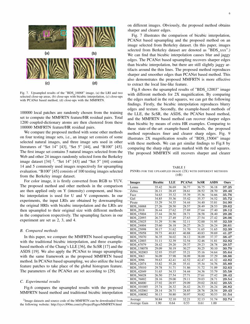
Fig. 7. Upsampled results of the ”BDS 16068” image, (a) the LRI and twoselected close-up areas, (b) close-ups with bicubic interpolation, (c) close-upswith PCANet based method, (d) close-ups with the MMFRTN.
100000 local patches are randomly chosen from the trainingset to compute the MMFRTN feature/HR residual pairs. Total1200 coupled-dictionary atoms are then clustered from these100000 MMFRTN feature/HR residual pairs.
We compare the proposed method with some other methodson four testing image sets, i.e., an image set consists of someselected natural images, and three image sets used in otherliteratures of “Set 14” [43], “Set 5” [44], and “B100” [45].The first image set contains 5 natural images selected from theWeb and other 24 images randomly selected form the Berkeleyimage dataset [34] 2. “Set 14” [43] and “Set 5” [44] contain14 and 5 commonly used images respectively for upsamplingevaluation. “B100” [45] consists of 100 testing images selectedfrom the Berkeley image dataset.
For color image, it is firstly converted from RGB to YUV.The proposed method and other methods in the comparisonare then applied only on Y (intensity) component, and bicu-bic interpolation is used for U and V components. In ourexperiments, the input LRIs are obtained by downsamplingthe original HRIs with bicubic interpolation and the LRIs arethen upsampled to their original size with different methodsin the comparison respectively. The upsampling factors in ourexperiment are set as 2, 3, and 4.
B. Compared methods
In this paper, we compare the MMFRTN based upsamplingwith the traditional bicubic interpolation, and three example-based methods of the Chang’s LLE [36], the ScSR [17] and theASDS [19]. We also apply the PCANet to image upsamplingwith the same framework as the proposed MMFRTN basedmethod. In PCANet based upsampling, we also utilize the localfeature patches to take place of the global histogram feature.The parameters of the PCANet are set according to [29].
C. Experimental results
Fig.6 compares the upsampled results with the proposedMMFRTN based method and traditional bicubic interpolation
2Image datasets and source code of the MMFRTN can be downloaded fromthe following website: http://zycv.890m.com/zyProjectPages/MMFRTN.html
on different images. Obviously, the proposed method obtainssharper and clearer edges.
Fig. 7 illustrates the comparison of bicubic interpolation,PCANet based upsampling and the proposed method on animage selected from Berkeley dataset. (In this paper, imagesselected from Berkeley dataset are denoted as ”BDS xxx”.)We can find that bicubic interpolation causes blur and jaggyedges. The PCANet based upsampling recovers sharper edgesthan bicubic interpolation, but there are still slightly jaggy ar-tifacts around the thin lines. The proposed method reproducessharper and smoother edges than PCANet based method. Thisalso demonstrates the proposed MMFRTN is more effectiveto extract the local line-like feature.
Fig.8 shows the upsampled results of ”BDS 12003” imagewith different methods for 2X magnification. By comparingthe edges marked in the red squares, we can get the followingfindings. Firstly, the bicubic interpolation reproduces blurryedges and texture. Secondly, the example-based methods ofthe LLE, the ScSR, the ASDS, the PCANet based method,and the MMFRTN based method can recover sharper edgesthan bicubic by means of extra HR examples. Comparing tothese state-of-the-art example-based methods, the proposedmethod reproduces finer and clearer sharp edges. Fig. 9illustrates 2X magnification results of ”BDS 15004” imagewith these methods. We can get similar findings to Fig.8 bycomparing the sharp edge areas marked with the red squares.The proposed MMFRTN still recovers sharper and clearer
TABLE IPSNRS FOR THE UPSAMPLED IMAGE (2X) WITH DIFFERENT METHODS
(DB)
Images Bicubic LLE PCANet ScSR ASDS OursLenna 35.42 36.69 36.77 36.75 36.18 37.25Zebra 26.11 28.45 28.61 28.52 28.70 29.40Face 34.63 35.32 35.39 35.36 34.66 35.76Girl 34.85 35.36 35.42 35.37 34.52 35.72Pirate 33.29 34.35 34.44 34.40 33.81 34.90BDS 16068 27.26 28.50 28.57 28.49 28.53 29.62BDS 2018 26.44 27.62 27.69 27.64 27.40 28.12BDS 15004 27.44 28.50 28.71 28.58 28.40 29.26BDS 22093 26.73 27.49 27.63 27.54 27.42 28.06BDS 23025 31.29 31.96 32.11 32.00 31.95 32.59BDS 24004 25.60 26.18 26.27 26.21 26.24 26.61BDS 25098 30.17 31.62 31.70 31.65 31.65 32.39BDS 35058 39.73 40.83 40.88 40.83 39.69 41.27BDS 35070 36.35 38.02 38.12 38.09 37.37 38.47BDS 12003 31.11 32.39 32.54 32.46 31.81 32.92BDS 67079 28.42 29.20 29.37 29.23 28.78 29.57BDS 138078 29.09 30.19 30.27 30.25 30.10 30.70BDS 302003 32.93 35.07 35.21 35.16 34.64 35.64BDS 3063 36.09 37.98 38.09 38.00 37.29 38.86BDS 3096 39.63 42.41 42.52 42.47 41.32 42.82BDS 12074 33.82 35.28 35.41 35.34 34.76 35.89BDS 35010 29.78 31.71 31.86 31.72 31.09 32.63BDS 42049 31.65 34.33 34.44 34.36 33.79 35.58BDS 56028 26.50 27.54 27.71 27.61 27.42 28.42BDS 76002 28.16 29.00 29.11 29.03 28.71 29.54BDS 86000 27.92 28.97 29.09 29.02 28.82 29.55BDS 101085 25.74 26.32 26.42 26.33 26.24 26.82BDS 102061 28.14 28.71 28.85 28.76 28.54 29.43BDS 108082 30.13 30.80 30.97 30.82 30.53 31.54
Average 30.84 32.10 32.21 32.13 31.74 32.74Average Gain 1.90 0.64 0.53 0.61 1.00

7
Fig. 8. Upsampled results of the ”BDS 12003” image, (a) with bicubic interpolation, (b) with the LLE [36], (c) with the PCANet [29], (d) with the ScSR[17], (e) with the ASDS [19], (f) with the MMFRTN.
Fig. 9. Upsampled results of the ”BDS 15004” image, (a) with bicubic interpolation, (b) with the LLE [36], (c) with the PCANet [29], (d) with the ScSR[17], (e) with the ASDS [19], (f) with the MMFRTN.
edges than these methods.
As aforementioned, simple gradient-based feature cannotwell model complex edges due to its limited discriminativecapability. Fig. 10 illustrates some close-ups of zigzag edgesupsampled by the ScSR, the ASDS, and the MMFRTN. Thefirst- and second-order derivative is used as the local featurein the ScSR and the ASDS. This feature is simply obtainedby calculating the grayscale difference along vertical andhorizontal directions and it cannot accurately characterize the
complex local edges. By comparing the zigzag edge areamarked with the red circles, we find that the ScSR andthe ASDS reproduce some unnatural black spots, while theproposed MMFRTN can recover sharp and natural edges.
Fig. 11 compares the 3X magnification results of ”monarch”image with different example-based methods. The example-based methods of the Chang’s method, the ScSR and theASDS can recover sharper edges than the bicubic interpola-tion, and the MMFRTN reproduces sharper and clearer edges

8
Fig. 10. Close-ups of upsampled results of the ”BDS 12074” image (2X). (a)close-up area, (b) close-ups of upsampled result with ScSR [17], (c) close-upsof upsampled result with ASDS [19], (d) close-ups of upsampled result withthe MMFRTN.
than these example-based methods.Fig. 12 shows upsampled results of ”zebra” image for 4X
magnification. By comparing the streaks, it can be seen thatthe MMFRTN reconstructs sharper and clearer edges thanother example-based methods. In order to visually comparethe acutance of different results, we further zoom up edges andmark the width of the edge with two red arrows, as illustratedin Fig. 12.
Fig. 13 illustrates the upsampled result of the MMFRTNwith large upsampling factor. The interpolated image is ex-tremely blurred when the upsampling factor increases to 8,while the proposed MMFRTN still recovers much sharperresults.
The 2X magnification results of different example-basedmethods on some natural images selected from web andBerkeley dataset are listed in Table I. The last row shows theaverage PSNR gains of the MMFRTN based method over othermethods. We can see that the PSNR values of the proposedmethod are higher than other example-based methods.
Table II lists the average PSNR values of 2X, 3X, and 4Xmagnification on three image datasets, i.e., “Set14”, “Set5”,and “B100”. We can get the following findings from TableII. Firstly, the MMFRTN still produces better results than thePCANet on these image datasets, and the proposed feature isthus more effective for image upsampling. Secondly, by com-paring results of the Chang’s LLE method and the MMFRTNbased method, we find that the proposed MMFRTN feature cancharacterize local edges much better than traditional gradient-based feature. Finally, the proposed method always achieveshigher average PSNR values than other methods for various
upsampling factors and image datasets.
VI. CONCLUSION
In this paper, we proposed a multi-level modified finiteRadon transform (MMFRTN) to extract the local line-likefeature. The proposed MMFRTN consisted of three stages, i.e.,the modified finite Radon transform (MFRT) based multi-levelfiltering stage, the local binary nonlinear mapping stage, andthe local feature pooling stage. Then we presented a MMFRTNbased image upsampling method by means of the MMFRTNfeature and locally linear embedding based reconstruction.Experimental results demonstrated the effectiveness of theproposed method over some state-of-the-art methods.
ACKNOWLEDGMENT
The authors would like to sincerely thank A. Giachetti, Q.Shan, W. S. Dong, J. C. Yang, and T. H. Chan for sharing thesource codes of the ICBI, the Shan’s, the ASDS, the ScSR,and the PCANet.
REFERENCES
[1] R. Keys,“Cubic convolution interpolation for digital image processing,”IEEE Trans. Acoustics Speech, Signal Process., vol. 29, no. 6, pp. 1153-1160, Dec. 1981.
[2] T. M. Lehmann, C. Gonner, and K. Spitzer, “Survey: Interpolationmethods in medical image processing,” IEEE Trans. Med. Imag., vol.18, no. 11, pp. 1049-1075, Nov. 1999.
[3] D. C. Van Essen, C. H. Anderson, and D. J. Felleman,“Information processing in the primate visual system: An integratedsystems perspective,” Science, vol. 255, no. 5043, pp. 419-423, 1992.
[4] S. Dai, M. Han, W. Xu, Y. Wu, and Y. Gong “Soft edge smoothnessprior for alpha channel super resolution,” in Proc. IEEE Conf. Comput.Vis. Pattern Recognit., Jun. 2007, pp. 1-8.
[5] X. Li and M. T. Orchard, “New edge-directed interpolation,” IEEETrans. Image Process., vol. 10, no. 10, pp. 1521-1527, Oct. 2001.
[6] R. Fattal, “Image upsampling via impose edge statistics,” ACM Trans.Graph., vol. 26, no. 3, Jul. 2007, Art. ID 95.
[7] J. Sun, Z. Xu, and H. Y. Shum, “Image super-resolution using gradientprofile prior,” in Proc. IEEE Conf. Comput. Vis. Pattern Recognit., 2008,pp. 1-8.
[8] L. Wang, S. Xiang, G. Meng, H. Wu, and C. Pan, “Edge-directed single image super-resolution via adaptive gradient magnitudeself-interpolation,” IEEE Trans. Circuits Syst. Video Technol., vol. 23,no. 8, pp. 1289-1299, Aug. 2013.
[9] D. Su and P. Willis, “Image interpolation by pixel-level data-dependenttriangulation,” Comput. Graph. Forum, vol. 23, no. 2, pp. 189-201, 2004.
[10] Q. Wang and R. K. Ward, “A new orientation-adaptive interpolationmethod,” IEEE Trans. Image Process., vol. 16, no. 4, pp. 889-900, Apr.2007.
[11] C. Zwart and D. Frakes, “Segment Adaptive Gradient Angle Interpola-tion,” IEEE Trans. Image Process., vol. 22, no. 8, pp. 2960-2969, Aug.2013.
[12] X. Liu, D. Zhao, R. Xiong, S. Ma, W. Gao, and H. Sun, “Imageinterpolation via regularized local linear regression,” IEEE Trans. ImageProcess., vol. 20, no. 12, pp. 3455-3469, Dec. 2011.
[13] Q. Wang, R. Ward, and J. Zou, “Contrast enhancement for enlargedimages based on edge sharpening,” in Proc. IEEE Int. Conf. ImageProces., Sep. 2005, vol. 2, pp. 1-4.
[14] Q. Shan, Z. Li, J. Jia, et al, “Fast image/video upsampling,” ACMTransactions on Graphics, vol. 27, 153, 2008.
[15] A. Giachett and N. Asuni, “Real-time artifact-free image upscaling,”IEEE Trans. Image Process., vol. 20, no. 10, pp. 2760-2768, Oct. 2011.
[16] W. T. Freeman, E. C. Pasztor, and O. T. Carmichael, “Learninglow-level vision,” Int. J. Comput. Vision, vol. 40, no. 1, pp. 25-47, Jun.2000.
[17] J. Yang, J. Wright, T. S. Huang, and Y. Ma, “Image super-resolutionvia sparse representation,” IEEE Trans. Image Process., vol. 19, no. 11,pp. 2861-2873, Nov. 2010.

9
TABLE IIAVERAGE PSNR VALUES (UPSAMPLING FACTORS ARE 2, 3, AND 4) ON THREE IMAGE DATASETS (”SET14”, ”SET5”, AND ”B100”) WITH DIFFERENT
METHODS (DB)
Set14 Set5 B1002X 3X 4X 2X 3X 4X 2X 3X 4X
Bicubic 30.36 27.67 26.06 33.64 30.38 28.42 29.35 27.17 25.95LLE 31.19 27.94 26.32 35.17 31.14 29.32 30.17 27.54 26.17ScSR 31.21 28.01 26.57 35.38 31.23 29.43 30.32 27.74 26.23ASDS 31.15 27.91 26.94 34.85 31.02 29.54 30.19 27.65 26.32PCANet 31.37 28.19 26.81 35.43 31.16 29.53 30.43 27.67 26.39MMFRTN 32.39 28.86 27.13 35.84 31.47 29.89 30.85 28.17 26.72
Fig. 11. Upsampled results of the ”monarch” image (3X), (a) with bicubic interpolation, (b) with the LLE [36], (c) with the ScSR [17], (d) with the ASDS[19], (e) with the MMFRTN.
[18] J. Yang, Z. Wang, Z. Lin, X. Shu, and T. Huang, “Bilevel sparsecoding for coupled feature spaces,” in Proc. IEEE Conf. Comput. Vis.Pattern Recognit., Jun. 2012, pp. 2360-2367.
[19] W. Dong, D. Zhang, G. Shi, X. Wu, “Image deblurring and super-resolution by adaptive sparse domain selection and adaptive regulariza-tion,” IEEE Trans. Image Process., vol. 20, no. 7, pp. 1838-1857, Jul.2011.
[20] D. Glasner, S. Bagon, and M. Irani, “Super-resolution from a singleimage,” in Proc. IEEE Int. Conf. Comput. Vis., Sep. 2009, pp. 349-356.
[21] G. Freedman, R. Fattal, “Image and video upscaling from local self-examples,” ACM Trans. Graph., vol. 30, no. 2, pp. 12-23, 2011.
[22] T. Ojala, M. Pietikainen, and T. Maenpaa, “Multiresolution gray-scaleand rotation invariant texture classification with local binary patterns,”IEEE Trans. Pattern Anal. Mach. Intell., vol. 24, no. 7, pp. 971-987,Jul. 2002.
[23] D. G. Lowe, “Object Recognition from Local Scale-Invariant Features,”in Proc. IEEE Int. Conf. Comput. Vis., Sep. 1999.
[24] N. Dalal, and B. Triggs, “Histograms of oriented gradients for humandetection,” in Proc. IEEE Conf. Comput. Vis. Pattern Recognit., Jun,2005, pp. 886-893.
[25] G. Hinton, S. Osindero, and Y. W. Teh, “A fast learning algorithm fordeep belief nets,” Neural Computation, vol. 18, no. 7, pp. 1527-1554,2006.
[26] A. Krizhevsky, I. Sutskever, and G. Hinton, “Imagenet classificationwith deep convolutional neural network,” Adv. Neural Inform. Process.Syst., 2012.
[27] K. Kavukcuoglu, P. Sermanet, et al, “Learning convolutional feature
hierarchies for visual recognition,” Adv. Neural Inform. Process. Syst.,2010.
[28] J. Bruna, and S. Mallat, “Invariant scattering convolution networks,”IEEE Trans. Pattern Anal. Ma.ch Intell., vol. 35, no. 8, pp. 1872-1886,Aug. 2013.
[29] T. H. Chan, K. Jia, S. Gao, et al, “PCANet: A Simple Deep LearningBaseline for Image Classification,” arXiv preprint arXiv:1404.3606,2014.
[30] D. S. Huang, W. Jia, and D. Zhang, “Palmprint verification basedon principal lines,” Pattern Recognition, vol. 41, no. 4, pp. 1316-1328,2008.
[31] F. Matus, J. Flusser, “Image Representations via a Finite RadonTransform,” IEEE Trans. Pattern Anal. Ma.ch Intell., vol. 15, no. 10,pp. 996-1006, Oct. 1993.
[32] Y. Zhao, R. Wang, W. Wang, and W. Gao, “High Resolution LocalStructure-Constrained Image Upsampling,” IEEE Trans. Image Process.,vol.24, no.11, pp.4394-4407, Nov. 2015
[33] T. Michaeli and M. Irani, “Nonparametric blind super-resolution,” inProc. IEEE Int. Conf. Comput. Vis., Dec. 2013, pp. 945-952.
[34] D. Martin, C. Fowlkes, D. Tal, and J. Malik, “A database of humansegmented natural images and its application to evaluating segmentationalgorithms and measuring ecological statistics,” in Proc. IEEE Int. Conf.Comput. Vis., 2001, pp. 416-423.
[35] L. Wang, H. Wu, and C. Pan, “Fast image upsampling via thedisplacement field,” IEEE Trans. Image Process., vol.23, no. 12, pp.5123-5135, Dec. 2014.
[36] H. Chang, D. Y. Yeung, and Y. Xiong, “Super-resolution through

10
Fig. 12. Upsampled results of the ”zebra” image (4X), (a) with bicubic interpolation, (b) with the LLE [36], (c) with the ScSR [17], (d) with the ASDS [19],(e) with the MMFRTN.
Fig. 13. Upsampled results of 8X magnification, (a) input LRI, (b) withbicubic interpolation, (c) with the MMFRTN.
neighbor embedding,” in Proc. IEEE Conf. Comput. Vis. Pattern Recog-nit., Jun. 2004, pp. 275-282.
[37] J. Sun, N. N. Zheng, H. Tao, and H. Shum, “Image hallucinationwith primal sketch priors,” in Proc. IEEE Conf. Comput. Vis. PatternRecognit., Jun. 2003, pp. 729-736.
[38] M. Turkan, D. Thoreau, and P. Guillotel, “Optimized neighborembeddings for single-image super-resolution,” in Proc. IEEE Int. Conf.Image Process., Sep. 2013, pp. 645-649.
[39] M. Turkan, D. Thoreau, and P. Guillotel, “Iterated neighbor em-beddings for image super-resolution,” in Proc. IEEE Int. Conf. ImageProcess., Oct. 2014, pp. 3887-3891.
[40] L. He, H. Qi, and R. Zaretzki, “Beta process joint dictionary learningfor coupled feature spaces with application to single image super-resolution,” in Proc. IEEE Conf. Comput. Vis. Pattern Recognit., Jun.2013, pp. 345 - 352.
[41] T. Peleg and M. Elad, “A statistical prediction model based on sparserepresentations for single image super-resolution,” IEEE Trans. ImageProcess., vol.23, no. 6, pp. 2569-2581, Jun. 2014.
[42] W. Dong, L. Zhang, G. Shi, and X. Li, “Nonlocally centralized sparserepresentation for image restoration,” IEEE Trans. Image Process.,vol.22, no. 4, pp. 1620-1630, Apr. 2013.
[43] R. Zeyde, M. Elad, and M. Protter, “On single image scale-up usingsparse-representations,” Curv. Surfaces, pp. 711- 730, 2010.
[44] M. Bevilacqua, A. Roumy, C. Guillemot, M. Morel, “Low-complexity single image super-resolution based on nonnegative neighborembedding,” in Proc. British Machine Vis. Conf., 2012, pp.1-10
[45] R. Timofte, V. D. Smet, and L. V. Gool, “Anchored neighborhoodregression for fast example-based super-resolution,” in Proc. IEEE Int.Conf. Comput. Vis., Dec. 2013, pp. 1920- 1927.
[46] H. Xu, G. Zhai, and X. Yang, “Single image super-resolution withdetail enhancement based on local fractal analysis of gradient,” IEEETrans. Circuits Syst. Video Technol., vol. 23, no. 10, pp. 1740-1754, Oct.2013.
Yang Zhao received the B.E. and the Ph.D. degreefrom department of automation, University of Sci-ence and Technology of China, in 2008 and 2013.
From September 2013, he is a Postdoctoral Fel-low with the School of Electronic and ComputerEngineering, Peking University Shenzhen GraduateSchool, China.
His research interests include image processingand pattern recognition.

11
Ronggang Wang (M’12) received his Ph.D. Degreefrom the Institute of Computing Technology, Chi-nese Academy of Sciences. He was a Research stuffin Orange (France telecom) Labs from 2006 to 2010.He is currently an Associate Professor with PekingUniversity Shenzhen Graduate School.
His research interest is on video coding and pro-cessing. He has done many technical contributionsto ISO/IEC MPEG and China AVS. He leadedthe MPEG Internet Video Coding (IVC) standard,served as MPEG IVC AHG co-chair since 2012,
and severed as AVS implementation sub-group co-chair since 2015. He hasauthored more than 50 papers in international journals and conferences, andheld more than 40 patents.
Wenmin Wang received the B.E degree in Com-puter Application from Harbin University of Scienceand Technology in 1983, then received the M.E. andthe Ph.D. degrees in Computer Architecture fromHarbin Institute of Technology, China, respectivelyin 1986 and 1989.
From 1992, he had 18 years of oversea industrialexperience in Japan and America. He came backacademia form the end of 2009, currently is a pro-fessor with the School of Electronic and ComputerEngineering of Peking University, China.
His current research interests include video analysis, multimedia retrieval,artificial intelligence and machine learning.
Wen Gao (M’92-SM’05-F’09) received the Ph.D.degree in electronics engineering from the Univer-sity of Tokyo, Japan, in 1991.
He is a Professor of computer science with PekingUniversity, China. Before joining Peking University,he was a Professor of computer science with theHarbin Institute of Technology from 1991 to 1995,and a Professor with the Institute of ComputingTechnology of Chinese Academy of Sciences. Hehas published extensively including five books andover 600 technical articles in refereed journals and
conference proceedings in the areas of image processing, video coding andcommunication, pattern recognition, multimedia information retrieval, multi-modal interface, and bioinformatics. He served on the editorial board for sev-eral journals, such as the IEEE TRANSACTIONS ON CIRCUITS AND SYSTEMSFOR VIDEO TECHNOLOGY, the IEEE TRANSACTIONS ON MULTIMEDIA,the IEEE TRANSACTIONS ON AUTONOMOUSMENTAL DEVELOPMENT, theEURASIP Journal of Image Communications, the Journal of Visual Com-munication and Image Representation. He chaired a number of prestigiousinternational conferences on multimedia and video signal processing, such asthe IEEE ICME and ACM Multimedia, and also served on the advisory andtechnical committees of numerous professional organizations.


![11.[23 36]quadrature radon transform for smoother tomographic reconstruction](https://static.fdocuments.us/doc/165x107/54825b12b07959520c8b478b/1123-36quadrature-radon-transform-for-smoother-tomographic-reconstruction.jpg)