Multi-Layered Automultiscopic Displays - The …cfg.mit.edu/sites/cfg.mit.edu/files/Ran12.pdf ·...
9
Pacific Graphics 2012 C. Bregler, P. Sander, and M. Wimmer (Guest Editors) Volume 31 (2012), Number 7 Multi-Layered Automultiscopic Displays Nicola Ranieri 1 Simon Heinzle 2 Quinn Smithwick 3 Daniel Reetz 3 Lanny S. Smoot 3 Wojciech Matusik 4 Markus Gross 1,2 1 ETH Zurich 2 Disney Research Zurich 3 Disney Research Glendale 4 MIT CSAIL Abstract Our hybrid display model combines multiple automultiscopic elements volumetrically to support horizontal and vertical parallax at a larger depth of field and better accommodation cues compared to single layer elements. In this paper, we introduce a framework to analyze the bandwidth of such display devices. Based on this analysis, we show that multiple layers can achieve a wider depth of field using less bandwidth compared to single layer displays. We present a simple algorithm to distribute an input light field to multiple layers, and devise an efficient ray tracing algorithm for synthetic scenes. We demonstrate the effectiveness of our approach by both software simulation and two corresponding hardware prototypes. Categories and Subject Descriptors (according to ACM CCS): I.3.1 [Computer Graphics]: Hardware Architecture— Three-dimensional displays; 1. Introduction Displays that provide the illusion of three dimensions have become increasingly popular. Although the majority of cur- rent 3D displays rely on the use of special glasses, it is gen- erally agreed that multi-view autostereoscopic displays – un- encumbered by glasses and providing a large viewing range – offer significant advantages. These displays make steady technological progress in terms of resolution and perceived quality. The illusion of three dimensions is created by physi- cally separating viewing rays originating from a display sur- face. However, extremely high resolution is usually required in order to satisfy the depth range of typical 3D scenes and to avoid aliasing artifacts. This problem is even more pro- nounced for displays that support both horizontal and verti- cal parallax. In this paper we introduce multi-layered automultiscopic displays for 4D light fields. Our hybrid display model vol- umetrically combines multiple automultiscopic layers and supports horizontal and vertical parallax, and it supports bet- ter accommodation cues than single layer elements. Further- more, multi-layered displays are able to use the available dis- play bandwidth more efficiently. The combined bandwidth of n layers only requires 1 n of the total ray count of a single layer display to show the same diffuse scene content with ap- proximated occlusions. An efficient algorithm can be used to decompose an input light field for such multi-layered config- urations. For synthetic scenes, we propose a very simple ex- tension to existing ray tracers that supports spatial and angu- lar anti-aliasing using super-sampling. In order to show the effectiveness of our approach, we simulate different config- urations of multi-layered automultiscopic displays. We also present two physical prototypes implementing our display model. The first prototype uses two parallax-based color displays that are superimposed onto the same optical path using a beam-splitter. The second prototype uses a varifo- cal mirror to optically replicate one integral imaging-based monochrome display onto multiple depth planes using tem- poral multiplexing, supporting up to 24 layers of depth. 2. Related Work Parallax barriers. Parallax barrier displays employ mod- ulated blocking patterns to provide different viewing rays for different viewing angles. This concept was introduced by Frederic Ives using static parallax stereograms [Ive03]. En- abled by the advent of LCD technology, Isono et al. [IYS93] proposed dynamic parallax barrier displays for autostereo- scopic content. Jacobs et al. [JMW * 03] later developed a parallax barrier display able to switch between a high- resolution 2D display and a lower resolution autostereo- scopic display. Kim et al. [KKK * 07] then extended this con- cept to time-multiplexed parallax barriers to improve the per- ceived spatial sampling resolution for automultiscopic dis- plays. Instead of increasing the sampling resolution, Perlin et al. [PPK00] and Peterka et al. [PKS * 08] tracked the viewer’s c 2012 The Author(s) Computer Graphics Forum c 2012 The Eurographics Association and Blackwell Publish- ing Ltd. Published by Blackwell Publishing, 9600 Garsington Road, Oxford OX4 2DQ, UK and 350 Main Street, Malden, MA 02148, USA.
Transcript of Multi-Layered Automultiscopic Displays - The …cfg.mit.edu/sites/cfg.mit.edu/files/Ran12.pdf ·...
Pacific Graphics 2012C. Bregler, P. Sander, and M. Wimmer(Guest Editors)
Volume 31 (2012), Number 7
Multi-Layered Automultiscopic Displays
Nicola Ranieri1 Simon Heinzle2 Quinn Smithwick3 Daniel Reetz3 Lanny S. Smoot3 Wojciech Matusik4 Markus Gross1,2
1ETH Zurich 2Disney Research Zurich 3Disney Research Glendale 4MIT CSAIL
AbstractOur hybrid display model combines multiple automultiscopic elements volumetrically to support horizontal andvertical parallax at a larger depth of field and better accommodation cues compared to single layer elements. Inthis paper, we introduce a framework to analyze the bandwidth of such display devices. Based on this analysis,we show that multiple layers can achieve a wider depth of field using less bandwidth compared to single layerdisplays. We present a simple algorithm to distribute an input light field to multiple layers, and devise an efficientray tracing algorithm for synthetic scenes. We demonstrate the effectiveness of our approach by both softwaresimulation and two corresponding hardware prototypes.
Categories and Subject Descriptors (according to ACM CCS): I.3.1 [Computer Graphics]: Hardware Architecture—Three-dimensional displays;
1. Introduction
Displays that provide the illusion of three dimensions havebecome increasingly popular. Although the majority of cur-rent 3D displays rely on the use of special glasses, it is gen-erally agreed that multi-view autostereoscopic displays – un-encumbered by glasses and providing a large viewing range– offer significant advantages. These displays make steadytechnological progress in terms of resolution and perceivedquality. The illusion of three dimensions is created by physi-cally separating viewing rays originating from a display sur-face. However, extremely high resolution is usually requiredin order to satisfy the depth range of typical 3D scenes andto avoid aliasing artifacts. This problem is even more pro-nounced for displays that support both horizontal and verti-cal parallax.
In this paper we introduce multi-layered automultiscopicdisplays for 4D light fields. Our hybrid display model vol-umetrically combines multiple automultiscopic layers andsupports horizontal and vertical parallax, and it supports bet-ter accommodation cues than single layer elements. Further-more, multi-layered displays are able to use the available dis-play bandwidth more efficiently. The combined bandwidthof n layers only requires 1
n of the total ray count of a singlelayer display to show the same diffuse scene content with ap-proximated occlusions. An efficient algorithm can be used todecompose an input light field for such multi-layered config-urations. For synthetic scenes, we propose a very simple ex-
tension to existing ray tracers that supports spatial and angu-lar anti-aliasing using super-sampling. In order to show theeffectiveness of our approach, we simulate different config-urations of multi-layered automultiscopic displays. We alsopresent two physical prototypes implementing our displaymodel. The first prototype uses two parallax-based colordisplays that are superimposed onto the same optical pathusing a beam-splitter. The second prototype uses a varifo-cal mirror to optically replicate one integral imaging-basedmonochrome display onto multiple depth planes using tem-poral multiplexing, supporting up to 24 layers of depth.
2. Related Work
Parallax barriers. Parallax barrier displays employ mod-ulated blocking patterns to provide different viewing raysfor different viewing angles. This concept was introduced byFrederic Ives using static parallax stereograms [Ive03]. En-abled by the advent of LCD technology, Isono et al. [IYS93]proposed dynamic parallax barrier displays for autostereo-scopic content. Jacobs et al. [JMW∗03] later developeda parallax barrier display able to switch between a high-resolution 2D display and a lower resolution autostereo-scopic display. Kim et al. [KKK∗07] then extended this con-cept to time-multiplexed parallax barriers to improve the per-ceived spatial sampling resolution for automultiscopic dis-plays. Instead of increasing the sampling resolution, Perlin etal. [PPK00] and Peterka et al. [PKS∗08] tracked the viewer’s
c© 2012 The Author(s)Computer Graphics Forum c© 2012 The Eurographics Association and Blackwell Publish-ing Ltd. Published by Blackwell Publishing, 9600 Garsington Road, Oxford OX4 2DQ,UK and 350 Main Street, Malden, MA 02148, USA.
Ranieri et al. / Multi-Layered Automultiscopic Displays
location to adapt stereoscopic content. More recently, Lan-man et al. [LHKR10] introduced content-adaptive parallaxdisplays that dynamically optimize the barriers based on fac-tored light field data.
Integral imaging. In 1908, Lippmann [Lip08] publishedhis seminal paper on integral imaging. He proposed usingsmall lenticular lenses to provide different viewing rays fordifferent angles, similar to parallax barriers but at higherbrightness. Many improvements to Lippmann’s basic lentic-ular array idea have been proposed, and a thorough overviewof recent advances is given in [KHL10]. For instance, appar-ent resolution can be enhanced by using slanted lenticularsheets arranged with respect to LCD subpixels [Ber99] or byspatio-temporal multiplexing [JJ02]. Fuchs et al. [FRSL08]present a display system based on regular lenticulars which,in contrast to all prior work, relies additionally on theincident illumination angles to support ambient lighting-dependent effects. Kao et al. [KHY∗09] present a displaythat changes the focal length of all lenses simultaneously inorder to adapt to the viewer’s distance.
Volumetric displays. Instead of multiplexing light raysfor different directions, volumetric displays create a vol-ume of individually controlled light sources. Tamura andTanaka [TT82] employed beam-splitters to superimposemultiple 2D displays onto a single optical path. In contrastto a multi-layer approach, Buzak [Buz85] developed a field-sequential display using a set of electrically switchable bi-state mirrors that reflect or transmit the light dynamicallyto change the apparent distance to the display plane. Le-ung et al. [LIE98] proposed using a light panel followed bya stack of light absorbing LCD panels to achieve a depthvolume, similar to the multi-layered displays of PureDepthInc. [BCP∗08]. Gold and Freeman [GF98] developed a field-sequential display system using a projector in conjunctionwith set of bi-state optical shutters able to switch betweentransparent and translucent state. The DepthCube systemby Sullivan [Sul04] extended this concept by employinga high-speed projector and 20 shutter screens. Suyama etal. [STUS00, SSH∗04] built systems that approximate depthby interpolating between two different depth planes, andmore recently, Uehira [Ueh07] studied the ability of the hu-man visual system to fuse two different autostereoscopic dis-plays positioned at different depth planes. Traub [Tra67] pre-sented a volumetric display based on a vibrating varifocalmirror to extrude a display surface into space, thus creatingmultiple display layers. For a more comprehensive overviewof previous volumetric displays, we refer to Favalora’s sur-vey article [Fav05]. Unfortunately, all of these volumetricdisplays cannot represent occlusion or view-dependent ef-fects.
There are a few notable volumetric displays capable ofproviding occlusion. The static multi-layer display presentedby Holroyd et al. [HBLM11] uses display layers printed ontransparencies embedded between acrylic plates. The closely
related displays by Cossairt et al. [CNH∗07] and Jones etal. [JMY∗07] effectively display a 360 degree light field ofa scene within the working volume. Although called volu-metric, these displays are, in fact, quite similar to parallaxbarriers. Instead of using blocking patterns to provide differ-ent viewing rays for different viewing angles, they employtime multiplexing with a high-speed projector and a rotatingvertical anisotropic mirror to attain the same effect. Finally,the display system by Akeley et al. [AWGB04] supports trueautostereoscopic viewing with occlusion and better accom-modation cues, but for one fixed viewpoint only.
Multi-layer displays. Gotoda [Got10] presented a noveldisplay device by stacking multiple LCD panels on the topof a uniform light source. His display uses volumetric at-tenuation to display autostereoscopic content. Wetzstein etal. [WLHR11] extended the idea and employed tomographicreconstruction techniques to create this light-attenuating vol-ume to display 4D light field images. Their thorough band-width analysis showed that the available bandwidth can beused more efficiently compared to single-layer automulti-scopic displays, at a moderate field of view. Lanman etal. [LWH∗11] adapt this technique by reformulating theproblem to switching LCDs instead of modulating layers,and show a real-time prototype using multiple stacked LCDscreens. Most recently, Wetzstein et al. [WLHR12] extendedthis concept to multiple stacked LCD screens combined withtemporal multiplexing and directional backlighting to en-hance the field of view and display quality of attenuation-based multi-layer displays.
Multi-layered automultiscopic displays. Similar to pre-vious work, our display prototype also consist of multiplelayers: however, instead of attenuating light, our display ad-ditively combines multiple parallax based displays to in-crease the effective bandwidth usage. In contrast to previousvolumetric displays based on multiple layers, our display isa hybrid volumetric display with view dependent pixels, andour display is therefore able to support with occlusion in ad-dition to relatively wide viewing angles and parallax.
3. Multi-Layered Automultiscopic Displays
In this paper we introduce multi-layered automultiscopicdisplays, a hybrid display model that combines the bene-fits of volumetric and parallax-based displays. The idea isvery simple: multiple translucent display layers at differentdepths are combined onto the same optical path. In contrastto previous volumetric displays, each of the layers is com-prised of an automultiscopic layer to emit true view depen-dent rays. Our display model is therefore very similar to vol-umetric displays, however, capable of view-dependent oc-clusion.
Figure 1 illustrates this concept for a dual-layer config-uration. Each automultiscopic layer consists of two planes.Rays are generated on the emissive back plane with angular
c© 2012 The Author(s)c© 2012 The Eurographics Association and Blackwell Publishing Ltd.
Ranieri et al. / Multi-Layered Automultiscopic Displays
Δx
ΔuΔv
Δy
d0zD
View
dep
ende
nt ra
ys
Automultiscopic layer 1 Automultiscopic layer 2
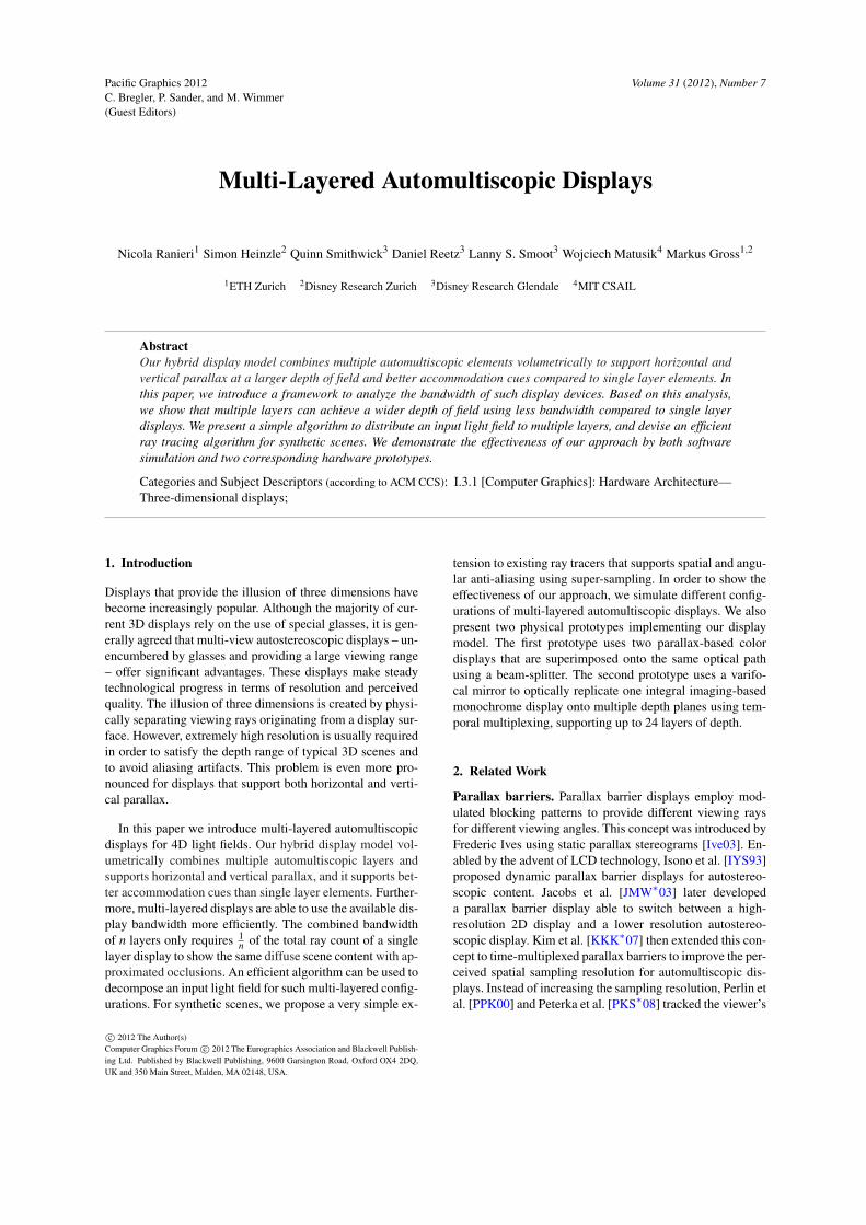
Figure 1: Multi-layered automultiscopic display for 4Dlight fields. Each layer consists of an automultiscopic dis-play, e.g. using parallax barriers (shown here) or lenslet ar-rays. The layers are multiplexed on the same optical path.Rays are generated on an emissive plane, and spatially sep-arated into view-dependent rays on the modulating plane.
sampling (∆u,∆v). The emissive pixels are spatially sepa-rated into view-dependent rays, using pinholes on the modu-lating front plane, with spatial sampling (∆x,∆y). The emis-sive and modulating plane of each layer are separated by adistance d0, the layers themselves are positioned at a dis-tance zD apart. The individual automultiscopic layers arethen superimposed onto the same optical path, at differentdepths. Note that we assume that our layers cannot supporttrue occlusion, i.e., a display layer cannot block light fromany back layer.
3.1. Light Field Distribution
For a given display configuration, the input light field`IN(x,y,u,v) needs to be distributed to the individual dis-play layers Layeri. In principle, our distribution algorithm isvery simple. For each output light field `OUTi , assign eachray from `IN to the display layer Layeri closest to the rayorigin.
Due to the nature of our display, front layers cannot blockincoming light from the back layers. Such occlusions canimplicitly be handled by the light field distribution: occlu-sions are represented as rays with zero luminance in therespective output light fields `OUTi . Intuitively, these occlu-sions correspond to a shadow that is cast by an occluder onall the following display planes. Note, that rays generatedoutside the depth range of the layers (including object shad-ows) can lead to aliasing. In order to avoid such aliasing, theoutput light fields need to be filtered accordingly, e.g. usinga method similar to [ZMDP06]. Algorithm 1 summarizes thelight field distribution.
3.2. Ray Tracing Algorithm
Algorithm 1 assumes known depth information for the inputlight field. For synthetic scenes, this information is alreadygiven, and the algorithm can be reformulated as simple mod-ification to any given ray tracing framework. For each layer,the respective depth range is determined. Then, ray trac-ing is performed within this depth range only. To achieveanti-aliasing comparable to [ZMDP06], we employ spatio-angular multi-sampling: instead of casting one ray only, westochastically sample the original (x,y,u,v) sampling loca-tions. Algorithm 2 summarizes our extension, note that thedepth range of the outermost layers is extended to ±∞, inorder to capture the whole scene.
4. Bandwidth Analysis
In this section we will evaluate the effective bandwidth us-age of multi-layered automultiscopic displays. We will startby introducing the bandwidth of a single layer, and willshow that much of the available display bandwidth for 4Dlight fields is unused. We will then show that multiple layerscan represent the same frequency content using less overallbandwidth.
Without loss of generality, we will assume a display withuniform spatial sampling ∆x = ∆y and uniform angular sam-pling ∆u = ∆v as well as unit spacing d0 = 1 between the(x,y) and (u,v) planes for this derivation.
4.1. Bandwidth of Single Layer
The bandwidth of an automultiscopic display is defined asthe range of all possible frequencies that can be representedby the display. As noted by Zwicker et al. [ZMDP06], themaximum spatial and angular frequencies are delimited byπ
∆x and π
∆u . The bandwidth of a display is then defined as
H(ωx,ωy,ωu,ωv) =
{1, for |ωx,y| ≤ π
∆x , |ωu,v| ≤ π
∆u ,
0, otherwise.
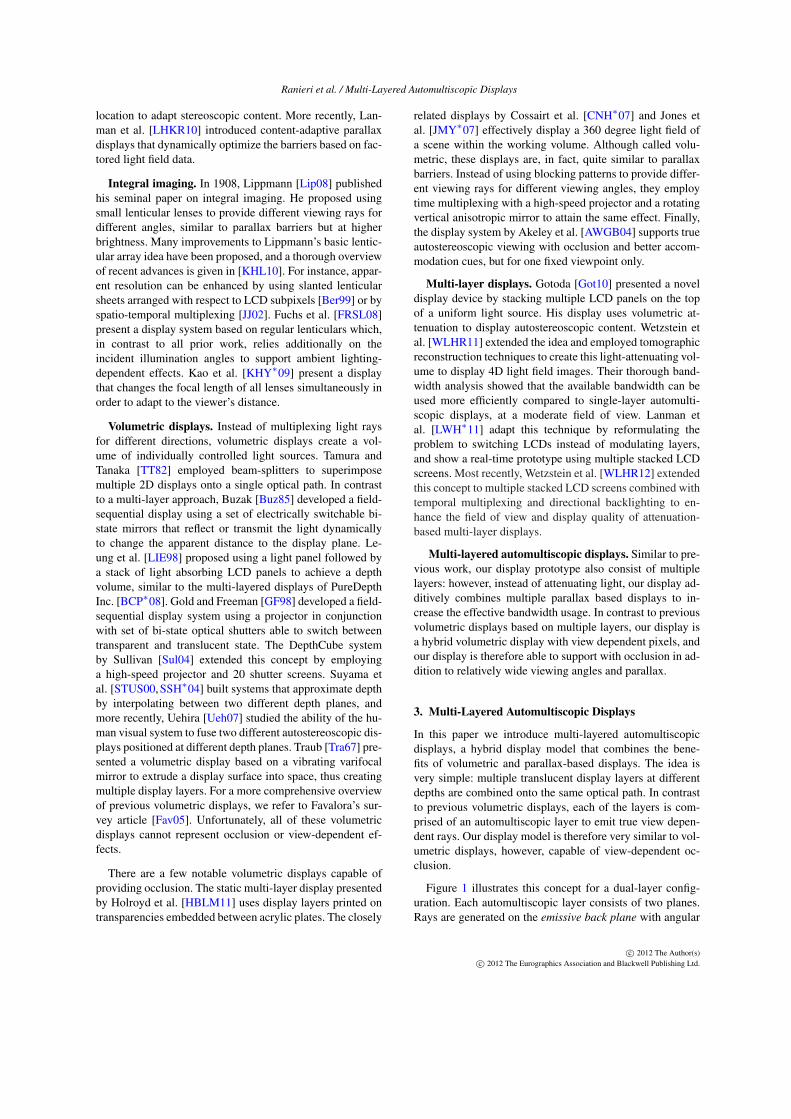
The bandwidth corresponds to a 4D hyperbox with volume(2π/∆x)2 · (2π/∆u)2, see Figure 2 for an illustration using a2D cut. As also noted by Zwicker et al. [ZMDP06], much ofthe available bandwidth will be unused.
According to [CTCS00, LD10], the light field ` of aLambertian plane parallel to the display plane will onlyexhibit frequency entries on a 2D plane. Therefore, the
Algorithm 1: Light field distribution overview
for all rays of input light field `INFind closest display Layeri to ray originAssign ray to output light field `OUTi
for all Layeri`OUTi = pre f ilter(`OUTi)
c© 2012 The Author(s)c© 2012 The Eurographics Association and Blackwell Publishing Ltd.
Ranieri et al. / Multi-Layered Automultiscopic Displays
Algorithm 2: Light field ray tracing overview
Determine depth ranges of all layersfor each Layeri
for each sample s emitted from display:Generate n rays sampled around (xs,ys,us,vs)Intersect rays with sceneAssign zero luminance if intersection is not in rangeFilter rays
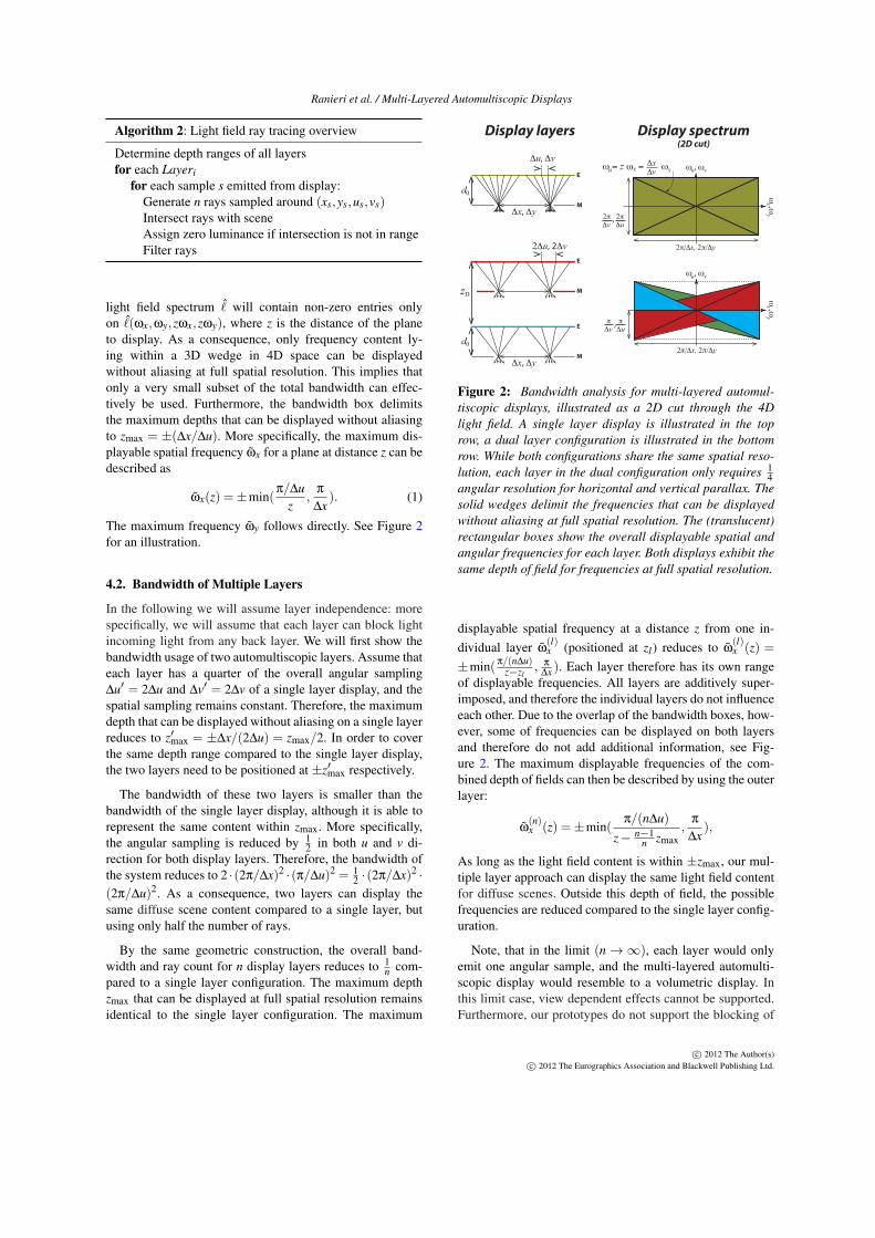
light field spectrum ˆ̀ will contain non-zero entries onlyon ˆ̀(ωx,ωy,zωx,zωy), where z is the distance of the planeto display. As a consequence, only frequency content ly-ing within a 3D wedge in 4D space can be displayedwithout aliasing at full spatial resolution. This implies thatonly a very small subset of the total bandwidth can effec-tively be used. Furthermore, the bandwidth box delimitsthe maximum depths that can be displayed without aliasingto zmax = ±(∆x/∆u). More specifically, the maximum dis-playable spatial frequency ω̃x for a plane at distance z can bedescribed as
ω̃x(z) =±min(π/∆u
z,
π
∆x). (1)
The maximum frequency ω̃y follows directly. See Figure 2for an illustration.
4.2. Bandwidth of Multiple Layers
In the following we will assume layer independence: morespecifically, we will assume that each layer can block lightincoming light from any back layer. We will first show thebandwidth usage of two automultiscopic layers. Assume thateach layer has a quarter of the overall angular sampling∆u′ = 2∆u and ∆v′ = 2∆v of a single layer display, and thespatial sampling remains constant. Therefore, the maximumdepth that can be displayed without aliasing on a single layerreduces to z′max = ±∆x/(2∆u) = zmax/2. In order to coverthe same depth range compared to the single layer display,the two layers need to be positioned at ±z′max respectively.
The bandwidth of these two layers is smaller than thebandwidth of the single layer display, although it is able torepresent the same content within zmax. More specifically,the angular sampling is reduced by 1
2 in both u and v di-rection for both display layers. Therefore, the bandwidth ofthe system reduces to 2 ·(2π/∆x)2 ·(π/∆u)2 = 1
2 ·(2π/∆x)2 ·(2π/∆u)2. As a consequence, two layers can display thesame diffuse scene content compared to a single layer, butusing only half the number of rays.
By the same geometric construction, the overall band-width and ray count for n display layers reduces to 1
n com-pared to a single layer configuration. The maximum depthzmax that can be displayed at full spatial resolution remainsidentical to the single layer configuration. The maximum
ω ,ωx
yω
,ωx
y
2πΔv
2πΔu
2π/Δx, 2π/Δy
ω , ωu v
ω , ωu v
πΔu
πΔv
2π/Δx, 2π/Δy
Δu, Δv
d0
M
E
Δx, Δy
2Δu, 2Δv
M
E
d0
zD
M
E
Δx, Δy
Display layers Display spectrum(2D cut)
ω = z ω = ω u x ΔvΔx
x
,
,
Figure 2: Bandwidth analysis for multi-layered automul-tiscopic displays, illustrated as a 2D cut through the 4Dlight field. A single layer display is illustrated in the toprow, a dual layer configuration is illustrated in the bottomrow. While both configurations share the same spatial reso-lution, each layer in the dual configuration only requires 1
4angular resolution for horizontal and vertical parallax. Thesolid wedges delimit the frequencies that can be displayedwithout aliasing at full spatial resolution. The (translucent)rectangular boxes show the overall displayable spatial andangular frequencies for each layer. Both displays exhibit thesame depth of field for frequencies at full spatial resolution.
displayable spatial frequency at a distance z from one in-dividual layer ω̃
(l)x (positioned at zl) reduces to ω̃
(l)x (z) =
±min( π/(n∆u)z−zl
, π
∆x ). Each layer therefore has its own rangeof displayable frequencies. All layers are additively super-imposed, and therefore the individual layers do not influenceeach other. Due to the overlap of the bandwidth boxes, how-ever, some of frequencies can be displayed on both layersand therefore do not add additional information, see Fig-ure 2. The maximum displayable frequencies of the com-bined depth of fields can then be described by using the outerlayer:
ω̃(n)x (z) =±min(
π/(n∆u)z− n−1
n zmax,
π
∆x),
As long as the light field content is within ±zmax, our mul-tiple layer approach can display the same light field contentfor diffuse scenes. Outside this depth of field, the possiblefrequencies are reduced compared to the single layer config-uration.
Note, that in the limit (n→∞), each layer would onlyemit one angular sample, and the multi-layered automulti-scopic display would resemble to a volumetric display. Inthis limit case, view dependent effects cannot be supported.Furthermore, our prototypes do not support the blocking of
c© 2012 The Author(s)c© 2012 The Eurographics Association and Blackwell Publishing Ltd.
Ranieri et al. / Multi-Layered Automultiscopic Displays
incoming light. In order to implicitly support occlusions forpurely additive layers, occlusions need to be represented asblack objects which can lead to aliasing. See Section 7 formore discussion.
If the frequency spectrum is much sparser, the overallbandwidth could be optimized even further for a given scene.For example, a scene could be comprised of a foreground ob-ject and a background object separated by a large distance.Then, the display layers could be separated by the same dis-tance in order to optimally use the respective bandwidths.If the scene or the depth separation changes, however, thedisplays would have to be reconfigured.
5. Software Framework
We implemented our light field distribution algorithm forray tracing within Optix [PBD∗10], a framework for gen-eral purpose ray tracing on the GPU. Our implementationperforms ray tracing for all layers in parallel, and all rays aregenerated according to the ray sampling of the layers. Anti-aliasing is achieved by stochastic super-sampling around theoriginal sampling locations, and all samples are interpolatedusing a box filter. Our ray tracer supports only basic ray-casting only but it could easily be extended for more realisticimage generation.
Layer borders. The layer distribution can introduce highfrequencies, especially when continuous surfaces are sepa-rated by two layers. In order to avoid noisy artifacts, a highnumber of multi-samples would be necessary. We mitigatethese issue using a different strategy. Instead of using binarycuts, our implementation employs ’fuzzy’ layer borders: weslightly overlap neighboring depth of fields, and we linearlyweight the corresponding samples that fall within the over-lapping region, with respect to the actual layer borders. Thisstrategy greatly reduces these artifacts without the need forvery high sampling densities.
Optimized field of view. Using regular sampling, manyrays will fall outside the field of view for close viewing po-sitions. In order to increase the effective ray utilization for agiven viewing position, the emitted view rays can be shearedalong the angular direction u′ = u + sx and v′ = v + sy′,where s is dependent on the display parameters and view-ing distance. In our implementation, we round the shearedrays to the nearest sampling location determined by the pixelgrid.
Display simulation. The simulated results have been gen-erated using a custom ray tracer implemented within theOptix framework. Each display layer is represented by twoplanes. The emitting plane is assigned a luminance texturecorresponding to the generated pattern from the light fielddistribution. The modulating plane is assigned a transmis-sion texture corresponding to the spatial sampling. For thesimulation, we apply super-sampling of the viewing rays toapproximate cross-talk.
6. Hardware Setups
We evaluate the effectiveness of our algorithm using twohardware prototypes. The first prototype uses two automulti-scopic layers superimposed onto the same optical path usinga beam-splitter with high resolution, while the second pro-totype allows us to demonstrate our technique with up to 24depth planes, but at lower resolution.
6.1. Beam-Splitter Prototype
The setup of the first prototype consists of two automulti-scopic layers which are combined onto the same optical pathusing a beam-splitter, as illustrated in Figure 3. Our customautomultiscopic layers are constructed using two LCD lay-ers stacked on top of each other. The back emissive layeris comprised of a regular LCD display with backlight. Thefront modulating layer consists of a disassembled and mod-ified LCD panel from a regular LCD display. The diffusingfront polarizer and the back polarizer have been removedand replaced with non-diffusing and matching polarizers, ro-tated by 90 degrees. In order to reduce Moire patterns, anadditional diffuser with a small point spread function of ap-proximately one pixel is placed in front of the back LCD.Both LCDs are then stacked on top of each other and phys-ically separated using a layer of acrylic glass. The assemblyof one individual layer is very similar to [LHKR10], withthe following differences. In their setup, the diffuser exhibitsa much larger point spread function, effectively reducingtheir available display resolution. Furthermore, their modu-lating LCD features only a front polarizer but no back polar-izer. Unfortunately, the diffuser to reduce the Moire patterndestroys much of the polarization from the emissive layer,and using a front polarizer only would not result in suffi-cient contrast. The LCD panels have been taken from a AcerHN274H display (27", 1920x1080, 120Hz). The panels aredriven from a dual-head NVIDIA GTX 580 graphics card.
In order to increase the perceived spatial resolution, weemploy time-multiplexing of the parallax barriers similar toKim et al. [KKK∗07]. Synchronization for one automulti-scopic layer is performed implicitly by the graphics board.Synchronization between the two automultiscopic layerswould require higher end graphics boards, and thus display-ing dynamic scenes is not possible with the current pro-totype. The alignment of the stacked LCDs as well as theautomultiscopic layers is currently performed using carefulmanual adjustment, and could be improved using more ad-vanced assembly setups and by using automated calibrationtechniques.
6.2. Varifocal Multi-Plane Display
For the second verification of our algorithm we use a setupsimilar to a recently proposed volumetric display [SSR12].In its original form, a 60Hz display is used in conjunc-tion with a high-speed DLP projector used as back-light.
c© 2012 The Author(s)c© 2012 The Eurographics Association and Blackwell Publishing Ltd.
Ranieri et al. / Multi-Layered Automultiscopic Displays
PARALLAXBARRIER DISPLAY
PARALLAXBARRIER DISPLAY
BEAMSPLITTER
Layer 1
Layer 2
Beamsplitt
er
Replicated virtual layer 2
Replicated virtual layer 1 Varifo
cal
beamsplitt
er
Concave mirror
Automultiscopic display
Virtual layers
DLP
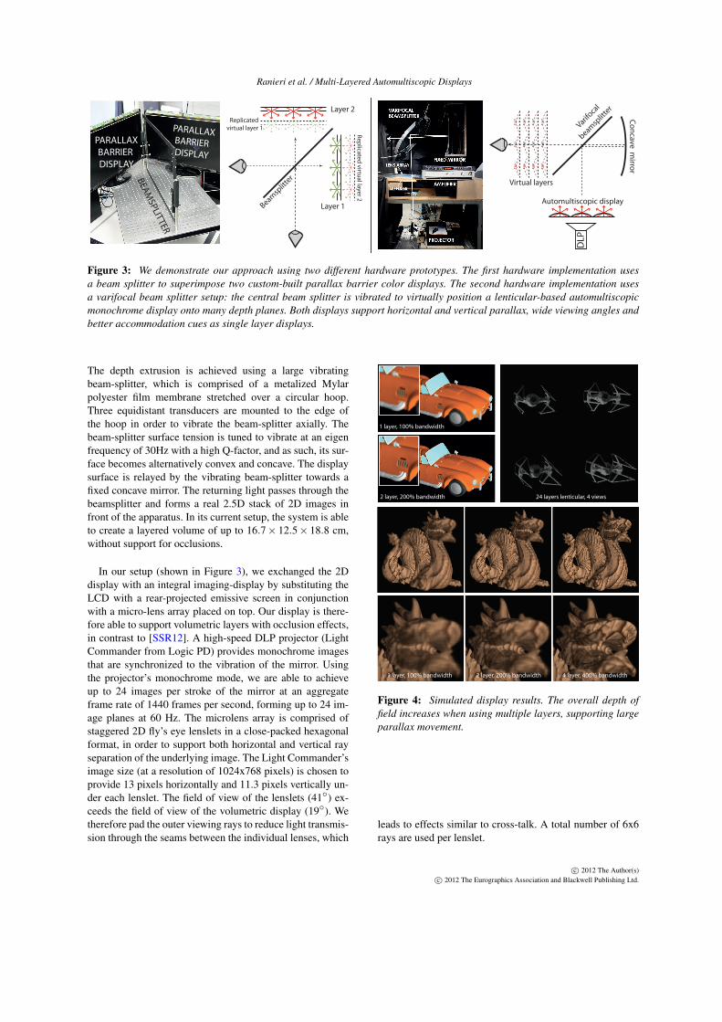
Figure 3: We demonstrate our approach using two different hardware prototypes. The first hardware implementation usesa beam splitter to superimpose two custom-built parallax barrier color displays. The second hardware implementation usesa varifocal beam splitter setup: the central beam splitter is vibrated to virtually position a lenticular-based automultiscopicmonochrome display onto many depth planes. Both displays support horizontal and vertical parallax, wide viewing angles andbetter accommodation cues as single layer displays.
The depth extrusion is achieved using a large vibratingbeam-splitter, which is comprised of a metalized Mylarpolyester film membrane stretched over a circular hoop.Three equidistant transducers are mounted to the edge ofthe hoop in order to vibrate the beam-splitter axially. Thebeam-splitter surface tension is tuned to vibrate at an eigenfrequency of 30Hz with a high Q-factor, and as such, its sur-face becomes alternatively convex and concave. The displaysurface is relayed by the vibrating beam-splitter towards afixed concave mirror. The returning light passes through thebeamsplitter and forms a real 2.5D stack of 2D images infront of the apparatus. In its current setup, the system is ableto create a layered volume of up to 16.7× 12.5× 18.8 cm,without support for occlusions.
In our setup (shown in Figure 3), we exchanged the 2Ddisplay with an integral imaging-display by substituting theLCD with a rear-projected emissive screen in conjunctionwith a micro-lens array placed on top. Our display is there-fore able to support volumetric layers with occlusion effects,in contrast to [SSR12]. A high-speed DLP projector (LightCommander from Logic PD) provides monochrome imagesthat are synchronized to the vibration of the mirror. Usingthe projector’s monochrome mode, we are able to achieveup to 24 images per stroke of the mirror at an aggregateframe rate of 1440 frames per second, forming up to 24 im-age planes at 60 Hz. The microlens array is comprised ofstaggered 2D fly’s eye lenslets in a close-packed hexagonalformat, in order to support both horizontal and vertical rayseparation of the underlying image. The Light Commander’simage size (at a resolution of 1024x768 pixels) is chosen toprovide 13 pixels horizontally and 11.3 pixels vertically un-der each lenslet. The field of view of the lenslets (41◦) ex-ceeds the field of view of the volumetric display (19◦). Wetherefore pad the outer viewing rays to reduce light transmis-sion through the seams between the individual lenses, which
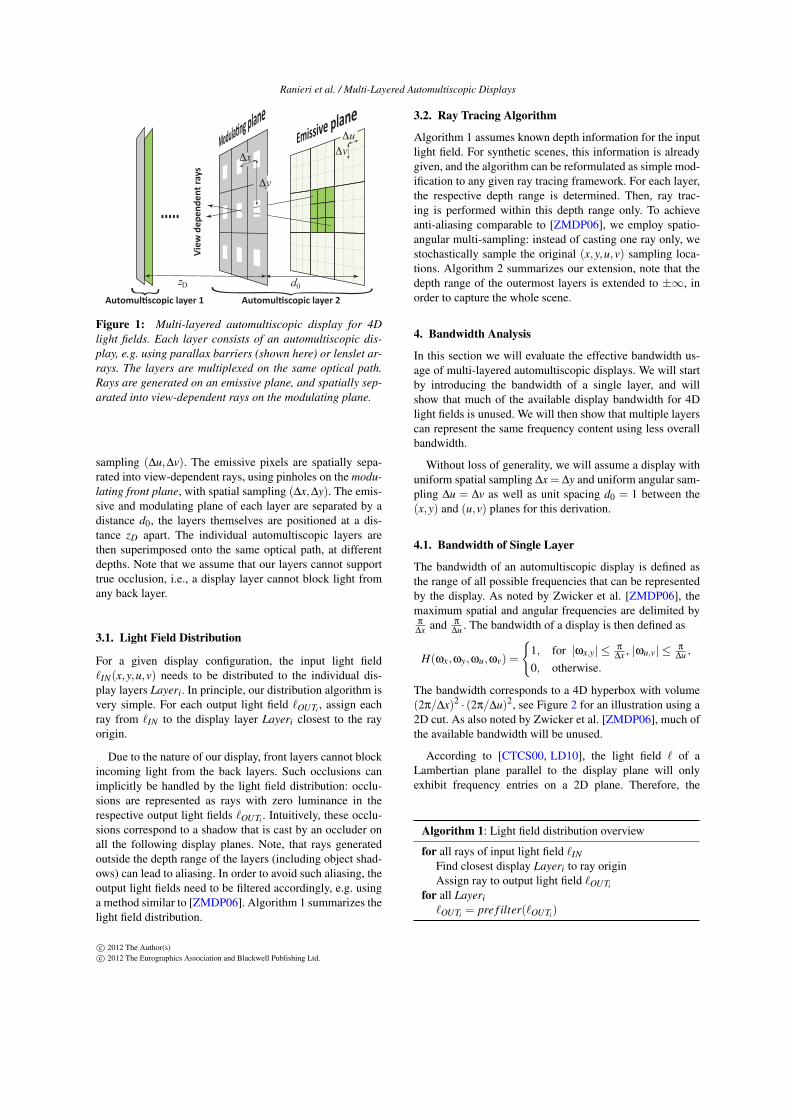
1 layer, 100% bandwidth
2 layer, 200% bandwidth
1 layer, 100% bandwidth 2 layer, 200% bandwidth 4 layer, 400% bandwidth
24 layers lenticular, 4 views
Figure 4: Simulated display results. The overall depth offield increases when using multiple layers, supporting largeparallax movement.
leads to effects similar to cross-talk. A total number of 6x6rays are used per lenslet.
c© 2012 The Author(s)c© 2012 The Eurographics Association and Blackwell Publishing Ltd.
Ranieri et al. / Multi-Layered Automultiscopic Displays
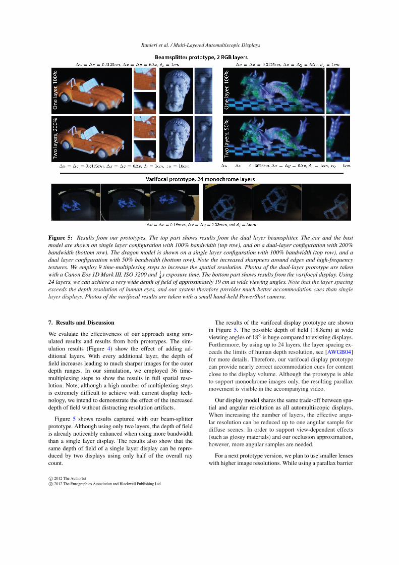
Figure 5: Results from our prototypes. The top part shows results from the dual layer beamsplitter. The car and the bustmodel are shown on single layer configuration with 100% bandwidth (top row), and on a dual-layer configuration with 200%bandwidth (bottom row). The dragon model is shown on a single layer configuration with 100% bandwidth (top row), and adual layer configuration with 50% bandwidth (bottom row). Note the increased sharpness around edges and high-frequencytextures. We employ 9 time-multiplexing steps to increase the spatial resolution. Photos of the dual-layer prototype are takenwith a Canon Eos 1D Mark III, ISO 3200 and 1
4 s exposure time. The bottom part shows results from the varifocal display. Using24 layers, we can achieve a very wide depth of field of approximately 19 cm at wide viewing angles. Note that the layer spacingexceeds the depth resolution of human eyes, and our system therefore provides much better accommodation cues than singlelayer displays. Photos of the varifocal results are taken with a small hand-held PowerShot camera.
7. Results and Discussion
We evaluate the effectiveness of our approach using sim-ulated results and results from both prototypes. The sim-ulation results (Figure 4) show the effect of adding ad-ditional layers. With every additional layer, the depth offield increases leading to much sharper images for the outerdepth ranges. In our simulation, we employed 36 time-multiplexing steps to show the results in full spatial reso-lution. Note, although a high number of multiplexing stepsis extremely difficult to achieve with current display tech-nology, we intend to demonstrate the effect of the increaseddepth of field without distracting resolution artifacts.
Figure 5 shows results captured with our beam-splitterprototype. Although using only two layers, the depth of fieldis already noticeably enhanced when using more bandwidththan a single layer display. The results also show that thesame depth of field of a single layer display can be repro-duced by two displays using only half of the overall raycount.
The results of the varifocal display prototype are shownin Figure 5. The possible depth of field (18.8cm) at wideviewing angles of 18◦ is huge compared to existing displays.Furthermore, by using up to 24 layers, the layer spacing ex-ceeds the limits of human depth resolution, see [AWGB04]for more details. Therefore, our varifocal display prototypecan provide nearly correct accommodation cues for contentclose to the display volume. Although the prototype is ableto support monochrome images only, the resulting parallaxmovement is visible in the accompanying video.
Our display model shares the same trade-off between spa-tial and angular resolution as all automultiscopic displays.When increasing the number of layers, the effective angu-lar resolution can be reduced up to one angular sample fordiffuse scenes. In order to support view-dependent effects(such as glossy materials) and our occlusion approximation,however, more angular samples are needed.
For a next prototype version, we plan to use smaller lenseswith higher image resolutions. While using a parallax barrier
c© 2012 The Author(s)c© 2012 The Eurographics Association and Blackwell Publishing Ltd.
Ranieri et al. / Multi-Layered Automultiscopic Displays
approach reduces the brightness considerably, using lenticu-lar arrays avoids this brightness loss at the cost of increasedcrosstalk. In addition, both prototypes employ optical stack-ing of multiple primitives which leads to a brightness reduc-tion of 1
n for each each individual layer, compared to usingone layer only. Due to the stacking of multiple layers, ourdisplays inherently do not support view repetitions that arecommonly found in parallax barrier or integral imaging dis-plays.
The varifocal mirror prototype only supportsmonochrome images and we hope to extend the sys-tem to a gray scale version using, for example, temporalsuper-sampling. Combining multiple pixels into one lu-minance value could be another option, by using higherresolution projectors in conjunction with diffusers that sup-port respective blur kernels. High speed color images mightbecome possible in the future, for example by combiningmultiple DLP chips into one optical system.
In our prototypes, the individual layers cannot block in-coming light from other layers and therefore occlusions can-not be handled correctly. Using the implicit occlusion han-dling of our light field distribution algorithm, the result-ing filtered object shadows will be blurred out. This canlead to noticeable black halos/shadows around the occluder,which becomes more pronounced for stronger parallax (i.e.for larger layer spacings). In our experiments, however, theshadow is barely noticeable due to the anti-alias filtering ofthe occluded regions. The varifocal mirror system only sup-ports monochrome images, and unfortunately no such filter-ing strategies can be applied unless multiple luminance val-ues would be supported.
Both display prototypes exhibit a substantial amount ofcross-talk, which results in additional blur. The customizedLCD layers furthermore exhibit a slight color difference, andlow contrast, which is most likely due to imprecise the align-ment of the emissive and modulating planes, as well as someslight shifts between the respective polarizers. Furthermore,alignment of the individual layers is performed manually atthe moment, and some object seams are visible due to theimperfect alignment. Using calibration techniques, this issuecould be mitigated.
8. Conclusion
In this paper, we introduced a hybrid display model thatcombines the advantages of volumetric and parallax-baseddisplays. These multi-layered automultiscopic displays areable to show a wide depth of field for horizontal and verti-cal parallax, large viewing angles, and better accommoda-tion cues that have been difficult to achieve by other dis-plays. We presented a corresponding bandwidth analysis,and showed that multiple layers can reproduce the same con-tent for diffuse scenes using a smaller ray count comparedto a single layer. A simple and efficient algorithm can be
used to distribute an input light field onto multiple layers,and we demonstrated a light-weight extension to existing raytracing frameworks in order to support synthetic scenes. Weevaluated the effectiveness of our display model using sim-ulations and two physical hardware prototypes. The proto-types show promising results, which we hope to improveas display technology advances. In addition to extensionslisted in the previous section, our work could possibly beextended by employing content-adaptive barrier techniquessuch as [LHKR10] or by shiftable lenslet techniques suchas [JJ02]. In its current formulation, the light-field distribu-tion algorithm requires known scene depth, but general inputlight fields could be supported by solving a constrained lin-ear system, similar to [WLHR11, LWH∗11].
References
[AWGB04] AKELEY K., WATT S. J., GIRSHICK A. R., BANKSM. S.: A stereo display prototype with multiple focal distances.ACM Transactions on Graphics 23, 3 (2004), 804–813. 2, 7
[BCP∗08] BELL G. P., CRAIG R., PAXTON R., WONG G.,GALBRAITH D.: Beyond flat panels: Multi-layered displays withreal depth. In SID Symposium Digest of Technical Papers, 39, 1(2008), pp. 352–355. 2
[Ber99] BERKEL C. V.: Image preparation for 3D-LCD. SPIEStereoscopic Displays and Virtual Reality Systems 3639 (1999),84–91. 2
[Buz85] BUZAK T. S.: A field-sequential discrete-depth-planethree-dimensional display. SID Symposium Digest (1985), 345–347. 2
[CNH∗07] COSSAIRT O. S., NAPOLI J., HILL S. L., DORVALR. K., FAVALORA G. E.: Occlusion-capable multiview volumet-ric three-dimensional display. Applied Optics 46 (2007), 1244–1250. 2
[CTCS00] CHAI J.-X., TONG X., CHAN S.-C., SHUM H.-Y.:Plenoptic sampling. In Proc. SIGGRAPH (2000), pp. 307–318.3
[Fav05] FAVALORA G.: Volumetric 3d displays and applicationinfrastructure. IEEE Computer 38, 8 (2005), 37–44. 2
[FRSL08] FUCHS M., RASKAR R., SEIDEL H.-P., LENSCH H.P. A.: Towards passive 6D reflectance field displays. ACMTransactions on Graphics 27, 3 (2008). 2
[GF98] GOLD R., FREEMAN J.: Layered display system andmethod for volumetric presentation. U.S. patent 5,813,742, 1998.2
[Got10] GOTODA H.: A multilayer liquid crystal display for au-tostereoscopic 3D viewing. In SPIE Stereoscopic Displays andVirtual Reality Systems 7524 (2010). 2
[HBLM11] HOLROYD M., BARAN I., LAWRENCE J., MATUSIKW.: Computing and fabricating multilayer models. ACMTransactions on Graphics 30, 6 (2011), 187:1–187:8. 2
[Ive03] IVES F.: Parallax stereogram and process for makingsame. U.S. Patent No. 725,567, 1903. 1
[IYS93] ISONO H., YASUDA M., SASAZAWA H.: Autostereo-scopic 3-D display using LCD-generated parallax barrier.Electronics and Communications in Japan (Part II: Electronics)76, 7 (1993), 77–84. 1
c© 2012 The Author(s)c© 2012 The Eurographics Association and Blackwell Publishing Ltd.
Ranieri et al. / Multi-Layered Automultiscopic Displays
[JJ02] JANG J.-S., JAVIDI B.: Improved viewing resolu-tion of three-dimensional integral imaging by use of non-stationary micro-optics. Optics Letters 27, 5 (2002), 324–326. URL: http://www.ncbi.nlm.nih.gov/pubmed/18007791. 2, 8
[JMW∗03] JACOBS A., MATHER J., WINLOW R., MONT-GOMERY D., JONES G., WILLIS M., TILLIN M., HILL L.,KHAZOVA M., STEVENSON H., BOURHILL G.: 2D/3D switch-able displays. Sharp Technical Journal, 4 (2003), 15–18. 1
[JMY∗07] JONES A., MCDOWALL I., YAMADA H., BOLAS M.,DEBEVEC P.: Rendering for an interactive 360 light field display.ACM Transactions on Graphics 26, 3 (2007), 40:1–40:10. 2
[KHL10] KIM Y., HONG K., LEE B.: Recent researches basedon integral imaging display method. 3D Research 1 (2010),17–27. URL: http://dx.doi.org/10.1007/3DRes.01(2010)2. 2
[KHY∗09] KAO Y.-Y., HUANG Y.-P., YANG K.-X., CHAO P.C.-P., TSAI C.-C., MO C.-N.: An auto-stereoscopic 3D displayusing tunable liquid crystal lens array that mimics effects of grinlenticular lens array. SID Symposium Digest of Technical Papers40 (2009), 111–114. 2
[KKK∗07] KIM Y., KIM J., KANG J.-M., JUNG J.-H., CHOIH., , LEE B.: Point light source integral imaging with improvedresolution and viewing angle by the use of electrically movablepinhole array. Optics Express 15, 26 (2007), 18253–18267. 1, 5
[LD10] LEVIN A., DURAND F.: Linear view synthesis using adimensionality gap light field prior. In CVPR (2010), pp. 1831–1838. 3
[LHKR10] LANMAN D., HIRSCH M., KIM Y., RASKAR R.:Content-adaptive parallax barriers: optimizing dual-layer 3D dis-plays using low-rank light field factorization. ACM Transactionson Graphics 29, 6 (2010), 163:1–163:10. 2, 5, 8
[LIE98] LEUNG M. S., IVES N. A., ENG G.: Three-dimensionalreal-image volumetric display system and method. U.S. patent5,745,197, 1998. 2
[Lip08] LIPPMANN G. M.: La photographie integrale.Comptes-Rendus 146 (1908), 446–451. 2
[LWH∗11] LANMAN D., WETZSTEIN G., HIRSCH M., HEI-DRICH W., RASKAR R.: Polarization fields: dynamic light fielddisplay using multi-layer LCDs. ACM Transactions on Graphics30, 6 (2011). 2, 8
[PBD∗10] PARKER S. G., BIGLER J., DIETRICH A.,FRIEDRICH H., HOBEROCK J., LUEBKE D., MCALLIS-TER D., MCGUIRE M., MORLEY K., ROBISON A., STICH M.:Optix: A general purpose ray tracing engine. ACM Transactionson Graphics 29 (2010), 66:1–66:13. 5
[PKS∗08] PETERKA T., KOOIMA R. L., SANDIN D. J., JOHN-SON A., LEIGH J., DEFANTI T. A.: Advances in the dynal-lax solid-state dynamic parallax barrier autostereoscopic visual-ization display system. IEEE Transactions on Visualization andComputer Graphics 14, 3 (2008), 487–499. 1
[PPK00] PERLIN K., PAXIA S., KOLLIN J. S.: An autostereo-scopic display. In Proc. SIGGRAPH (2000), pp. 319–326. 1
[SSH∗04] SUYAMA S., SAKUICHI, HIDEAKI O., KAZUTAKET., SAKAI U. S.: Apparent 3-D image perceived fromluminance-modulated two 2-D images displayed at differentdepths. Vision Research, 44 (2004), 785–793. 2
[SSR12] SMITHWICK Q., SMOOT L. S., REETZ D.: A volumet-ric display using a rim-driven varifocal beamsplitter and high-speed DLP backlit LCD. to appear at SID, 2012. 5, 6
[STUS00] SUYAMA S., TAKADA H., UEHIRA K., SAKAI S.: A
novel direct-vision 3-D display using luminance-modulated two2-D images displayed at different depths. SID Digest (2000),1208–1211. 2
[Sul04] SULLIVAN A.: DepthCube solid-state 3D volumetric dis-play. In SPIE Stereoscopic Displays and Virtual Reality Systems(2004), vol. 5291, pp. 279–284. 2
[Tra67] TRAUB A.: Stereoscopic display using rapid varifocalmirror oscillations. Applied Optics 6, 6 (1967), 1505–1511. 2
[TT82] TAMURA S., TANAKA K.: Multilayer 3-D display bymultidirectional beam splitter. Applied Optics 21 (1982), 3659–3663. 2
[Ueh07] UEHIRA K.: New depth-fused 3-D perception on 3-D display system using two stereoscopic displays. Journal ofElectronic Imaging 16, 3 (2007). 2
[WLHR11] WETZSTEIN G., LANMAN D., HEIDRICH W.,RASKAR R.: Layered 3D: Tomographic image synthesis forattenuation-based light field and high dynamic range displays.ACM Transactions on Graphics 30, 4 (2011). 2, 8
[WLHR12] WETZSTEIN G., LANMAN D., HIRSCH M.,RASKAR R.: Tensor Displays: Compressive Light Field Syn-thesis using Multilayer Displays with Directional Backlighting.ACM Transactions on Graphics 31, 4 (2012), 1–11. 2
[ZMDP06] ZWICKER M., MATUSIK W., DURAND F., PFIS-TER H.: Antialiasing for automultiscopic 3D displays. InEurographics Symposium on Rendering (2006). 3
c© 2012 The Author(s)c© 2012 The Eurographics Association and Blackwell Publishing Ltd.