MULTI-CHANNEL SIGNAL ANALYZER SA-02M -...
54
3-20-41 Higashimotomachi, Kokubunji, Tokyo 185-8533, Japan http://www.rion.co.jp/english/ HARDWARE INSTRUCTION MANUAL MULTI-CHANNEL SIGNAL ANALYZER SA-02M 4-CHANNEL SIGNAL ANALYZER SA-02A4
Transcript of MULTI-CHANNEL SIGNAL ANALYZER SA-02M -...

3-20-41 Higashimotomachi, Kokubunji, Tokyo 185-8533, Japan
http://www.rion.co.jp/english/
HARDWARE INSTRUCTION MANUALMULTI-CHANNEL SIGNAL ANALYZER
SA-02M4-CHANNEL SIGNAL ANALYZER
SA-02A4


i
Please read this fi rst
Thank you for selecting the multi-channel signal analyzer SA-02M/4-channel signal analyzer
SA-02A4. Please read these instructions carefully in order to ensure correct operation and make
full use of the advanced features of this product. You should keep the documentation at hand for
future reference.
Using the documentation
The product is supplied with the following two instruction manuals.
“Hardware instruction manual” (this document)
“Software instruction manual”
For information on system setup, power-on/power-off, equipment connections etc., please
refer to the hardware instruction manual.
For information on how to make parameter settings and perform measurement using the
measurement analysis software, please refer to the software instruction manual.
NOTE
• Unauthorized copying of the documentation, in whole or in part, is prohibited.
• The contents of the documentation and the product specifi cations may be changed at
any time without notice for improvements.
• Rion Corporation will not be held liable for any damages resulting from the use of this
product.

ii
iii
Organization of this manual
This manual describes the features and operation principles of the multi-channel signal analyzer
SA-02M/4-channel signal analyzer SA-02A4. For information regarding the operation of other
equipment in the case of incorporating the SA-02M/SA-02A4 into a measurement system with
other equipment, always make sure refer to the documentation of the other equipment. The fol-
lowing pages contain important information on safety. Be sure to read this part.
This manual contains the following sections.
OutlineProvides an outline of the unit.
Panel explanationExplains the switches, indicators, connectors, and all other parts on the panels of the
unit.
Preparations Explains how to set up the system, make power connections, connect the computer, con-
nect the copy protection key, etc.
Signal input/output Explains how to supply signals to the BNC input connectors and how to use the AC
output connectors.
External trigger signal input Explains how to supply an external trigger signal.
Tachometer signal input Explains how to supply a tachometer (rotary pulse) signal.
Specifi cations Lists the technical specifi cations of the unit.
* All company names and product names mentioned in this manual are trademarks
or registered trademarks of their respective owners.

iv
v
FOR SAFETY
In this manual, important safety instructions are specially marked as shown below. To
prevent the risk of death or injury to persons and severe damage to the unit or peripheral
equipment, make sure that all instructions are fully understood and observed.
Caution
WARNING
Important
Disregarding instructions printed
here incurs the risk of death or se-
vere injury to persons.
Disregarding instructions printed
here incurs the risk of injury to per-
sons and/or damage to peripheral
equipment.
Disregarding instructions printed
here incurs the risk of damage to the
unit.
Mentioned about the tips to use the
unit properly. (This messages do not
have to do with safety.)
Note

vi
Precautions
• Operate the unit only as described in this manual.
• Install the unit on a stable, horizontal surface.
• Do not install the unit in a location where it may be directly subject to vibrations or
shock.
• Do not install the unit in a location where it may be subject to splashes of water or
direct sunlight.
• Do not install the unit in a location with high levels of dust.
• Do not install the unit in a location with high temperatures or humidity levels.
• Do not install the unit in a location that may be subject to air with high salt or sulphur
content.
• Do not install the unit in a location that may be subject to gases or is in the vicinity of
stored chemicals.
• Do not use the unit in an environment where the rated temperature and humidity range
(0°C to 40°C, max. 90% RH) may be exceeded.
• Do not use the unit in an environment exposed to strong magnetic or electric fi elds or
radiation.
• Do not place any heavy objects on the unit or the cables.
• Before use, verify that all cable connections have been correctly and safely estab-
lished.
• Verify that the unit and all connected equipment operates normally.
• If a problem occurs during operation, disconnect the plug of the AC adapter from the
unit, in order to fully separate the unit from the power supply.
• After use, be sure to turn the power off and disconnect the AC adapter from the AC
outlet.
• When disconnecting cables, always hold the plug or connector and do not pull the
cable.
• If used in a way other than specifi ed by the manufacturer, the protection features of
the unit may be defeated.
• Do not insert any wire or other metal objects or objects made of conductive plastic into
any of the openings of the unit, to prevent the risk of damage.
• Do not disassemble the unit or attempt internal alterations.

vii
• When transporting or storing the unit, be sure to use the original packaging, to protect
the unit from vibrations, shock, dust etc.
• In case of malfunction, do not attempt any repairs. Note the condition of the unit clearly
and contact the supplier.
• Dispose of the unit only in accordance with national and local laws and regulations.

viii

ix
Contents
Organization of this manual ........................................................................iii
Outline ......................................................................................................... 1
System confi guration ............................................................................. 2
Panel explanation ......................................................................................... 4
Front panel .............................................................................................. 4
Rear panel ............................................................................................... 6
Right side panel ...................................................................................... 8
Preparations ................................................................................................. 9
Computer IP address setup .................................................................... 9
Installation ........................................................................................... 15
Power supply connections .................................................................... 15
Connection to the computer ................................................................. 17
Power-on ............................................................................................... 18
Power-off ............................................................................................. 18
Setting the IP address of the SA-02M/SA-02A4 .................................. 19
Connecting the copy protection key ..................................................... 23
Using two SA-02M units together ........................................................ 24
Signal input/output ..................................................................................... 26
Signal input via BNC connectors ......................................................... 26
Signal output ........................................................................................ 28
External trigger signal input ....................................................................... 29
Tachometer signal input ............................................................................ 30
Specifi cations ............................................................................................. 31

x

1
Outline
The SA-02M/SA-02A4 are signal analyzers that enable multi-channel FFT analysis as
well as octave band analysis, 1/3 octave band analysis, and 1/12 octave band analysis.
The products consist of the hardware (main unit) comprising the input section and signal
processing section, and dedicated software (optional) to be installed on a generic computer.
The main unit and the computer are connected via an Ethernet link.
The main unit is equipped with a DSP chip for high-speed signal processing, which al-
lows not only FFT analysis but also multi-channel 1/N octave band analysis in real time.
Simultaneous FFT analysis and 1/N octave band analysis are also possible.
Time waveform data can be stored in the memory of the computer, offering the capability
to perform more detailed offl ine analysis later.
The dedicated software installed on the computer runs under the Windows environment
and uses a sophisticated graphical interface. Data and analysis results can be handled and
managed further using applications such as Microsoft Excel and Word.
The compact dimensions of the main unit allow easy portability.
In the standard confi guration, the main unit has 4 input channels. The SA-02M can ac-
commodate additional units to increase the number of input channels to a maximum of 16.
A switching hub can be used to link two units, taking the maximum number of channels
to 32.
An optional signal output unit can be installed, for measurement scenarios where an out-
put signal is required. An input for a rotary pulse signal is also available, with optional
software that allows tracking analysis.
2
Outline
System confi guration
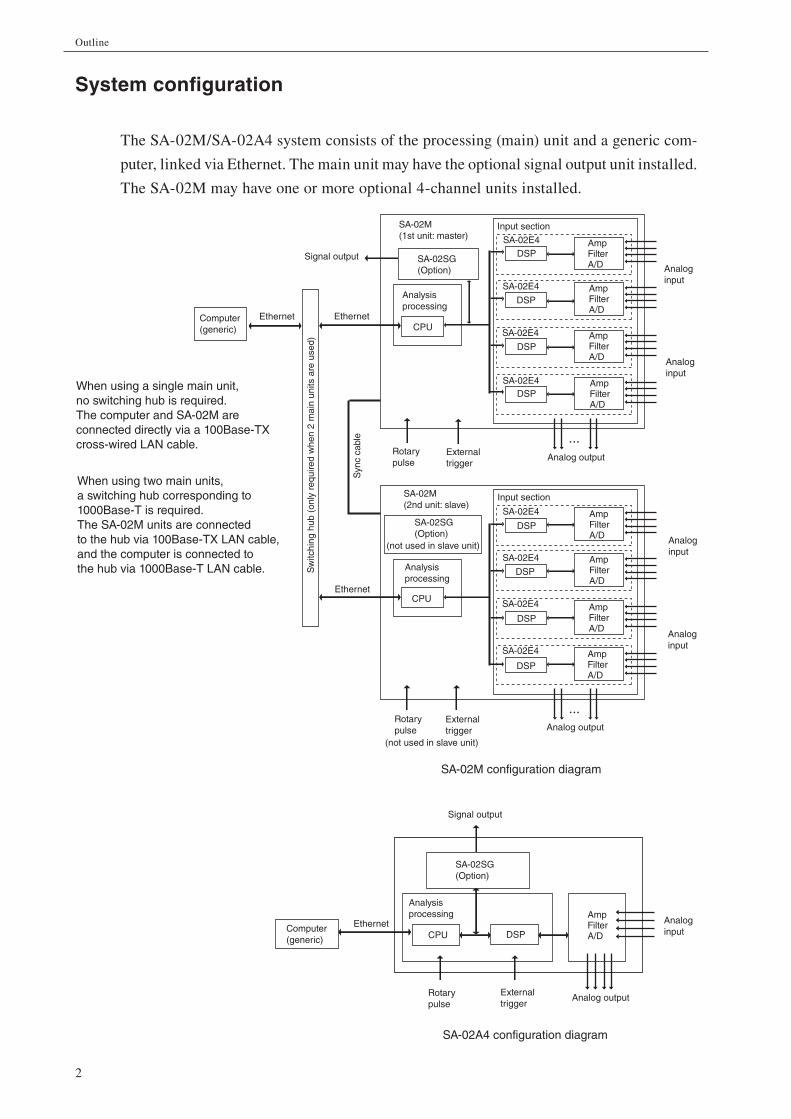
The SA-02M/SA-02A4 system consists of the processing (main) unit and a generic com-
puter, linked via Ethernet. The main unit may have the optional signal output unit installed.
The SA-02M may have one or more optional 4-channel units installed.
Computer(generic)
When using a single main unit,no switching hub is required.The computer and SA-02M areconnected directly via a 100Base-TXcross-wired LAN cable.
When using two main units,a switching hub corresponding to1000Base-T is required.The SA-02M units are connectedto the hub via 100Base-TX LAN cable,and the computer is connected tothe hub via 1000Base-T LAN cable.
EthernetEthernet
Signal output
SA-02M(1st unit: master)
SA-02M(2nd unit: slave)
SA-02SG(Option)
CPU
Input section
Analysisprocessing
SA-02E4
DSP
SA-02E4
DSP
SA-02E4
DSP
SA-02E4DSP
AmpFilterA/D
AmpFilterA/D
AmpFilterA/D
AmpFilterA/D
Analoginput
Analoginput
Analog outputExternaltrigger
Rotarypulse
Sw
itchi
nghu
b(o
nly
requ
ired
whe
n2
mai
nun
itsar
eus
ed)
Syn
cca
ble
(not used in slave unit)
CPU
SA-02SG(Option)
Ethernet
SA-02M configuration diagram
Analoginput
Analoginput
SA-02E4
DSP
SA-02E4
DSP
SA-02E4
DSP
SA-02E4
DSP
Analysisprocessing
Externaltrigger
(not used in slave unit)
Analog output
Input section
AmpFilterA/D
AmpFilterA/D
AmpFilterA/D
AmpFilterA/D
Rotarypulse
SA-02A4 configuration diagram
Computer(generic)
Ethernet
Analysisprocessing
CPU DSP
SA-02SG(Option)
Signal output
AmpFilterA/D
Analoginput
Analog outputExternaltrigger
Rotarypulse

3
Outline
Input section - AC coupling / DC coupling selectable for each channel individually.
- CCLD sensor, TEDS sensor supported.
- Frequency weighting fi lter (A, C characteristics), high-pass fi lter, low-pass fi lter
for each channel.
- Integrated amplifi er/attenuator (-40 dB to +20 dB range, 10-dB steps) for each
channel. Amplifi er/attenuator and frequency weighting applied to output signal
(full-scale 1 Vrms).
- A/D converter digitizes input signal and supplies data to analysis processing sec-
tion.
Analysis processing section - 32-bit fl oating point DSP handles input signal processing.
- Input signal processing and other processing results are sent to the computer via
Ethernet link.
Computer (for dedicated software) - Dedicated software can send commands to main unit hardware to control signal
processing, setup, data retrieval, FFT analysis, analysis result processing, display,
and other functions.
- Data are sent via Ethernet link.
Recommended computer specifi cations CPU: Intel Core2 Duo 2.0 GHz or higher (32-bit)
RAM: 2 GB or more
Display: XGA (1024 × 768 dots) or better, 65536 colors or more
Operating system:
Microsoft Windows XP Professional, Vista Business (32-bit versions)
LAN: 100 Base-TX (required)
1000 Base-T (when two SA-02M are connected)
CD-ROM drive (for SA-02 BASE installation)
USB port (for SA-02 BASE copy protection key)
Hardware Expansion - Option slot allows signal output unit SA-02SG installation.

4
Panel explanation
Front panel
SA-02M
SA-02A4
SA-02MSIGNAL ANALYZER
4
1
2
3
5
6
7
8 12
11
10
9
16
15
14
13
AC OUT
POWERswitch
AC output connectors
Indicators
The SA-02M has AC output connectors and indicators for 16 channels, but the output
connectors and indicators for channels that are not installed are inactive.
SA-02A4SIGNAL ANALYZER
1
AC OUT
2 3 4POWERswitch
AC output connectors
Indicators

5
Panel explanation
POWER switch Press the upper part ( | ) of the switch to turn the unit on, and press the lower part ( )
to turn the unit off. While power is on, the switch is lit or fl ashing.
Flashing of the POWER switch indicates that access from the computer to the SA-
02M/SA-02A4 is not possible (see “Power-on” on page 18).
AC output connectors These are 2.5 mm mono phone jacks that carry the AC signal for the respective
channel.
Indicators These LED indicators show the status of the respective channel by their color.
LED state Channel status
Off No measurement in channel
Lit green Channel selected, measurement in progress
Lit redChannel selected, measurement in progress, but overload has occurred
Note
A channel can only be used after having been selected. This pro-cess is performed using the dedicated software. For details, please refer to the software instruction manual.

6
Panel explanation
Rear panel
SA-02M
SA-02A4
LAN connector RJ-45 port for connection to the computer.
Option slot (SA-02M only) The optional signal output unit SA-02SG can be installed here.
Installation or removal of the unit is performed at the factory. Do not open the cover
of this slot.
DIRECT IN
1
2
3
4
TRIG IN
INIT
TACHO IN
SYNC
ID
DC 12V5A
LAN connector
Option slot
LAN setup initialize switch
Trigger input connector
Unit sync connector
DC input jack
Unit ID switch
Rotary pulseinput connector(TACHO IN)
BNC input connectors(DIRECT IN)
4-channel input unit slots
DIRECT INSIGNAL OUT
TRIG IN INIT
TACHO IN
DC-12V3A
123
1234
BNC input connectors(DIRECT IN)
LAN connector
LAN setup initialize switch
Trigger input connector
DC input jack
Option connector panel
Rotary pulseinput connector(TACHO IN)

7
Panel explanation
LAN setup initialize switch Press this switch to reset the settings for communication with the computer to the
default condition. (See “Hardware reset procedure” on page 22.)
Trigger input connector 2.5 mm mono phone jack for input of a trigger signal.
Unit sync connector (SA-02M only) RJ-45 port for linking two SA-02M units.
DC input jack The DC plug of the supplied AC adapter is to be connected here.
Unit ID switch (SA-02M only) When two SA-02M units are used in tandem, this switch serves for setting the identi-
fi cation number for the fi rst and second unit.
Rotary pulse input connector (TACHO IN)A rotary pulse (tachometer) signal can be input here, for tracking analysis.
BNC input connector (DIRECT IN) An AC output signal from a sound or vibration level meter or another kind of electri-
cal signal can be input here. The connector also has a provision for supplying sensor
drive power, which allows direct connection of equipment such as a piezoelectric ac-
celerometer with integrated preamplifi er.
4-channel input unit slots (SA-02M only) The optional 4-channel input unit SA-02E can be installed here.
Installation or removal of the 4-channei input unit is performed at the factory. Do not
open the cover of this slot.
Option connector panel (SA-02A4 only) If the optional signal output unit SA-02SG is installed, the SIGNAL OUT connector
is located here. Otherwise, the opening is covered by a grommet.
Installation or removal of the signal output unit is performed at the factory. Do not
remove the grommet.

8
Panel explanation
Right side panel
Handle (SA-02M only) Serves for carrying the unit.
Handle

9
Preparations
Computer IP address setup
In order for the SA-02M/SA-02A4 to be able to communicate with the computer, the IP
address of the computer must be set up as follows.
Setup procedure when using Windows XP
1. On the computer connected to the SA-02M/SA-02A4, click [Start] in the bottom left
corner of the screen and select [Control Panel] from the start menu that appears.
2. On the [Control Panel] screen, click [Network and Internet Connections].
10
Preparations
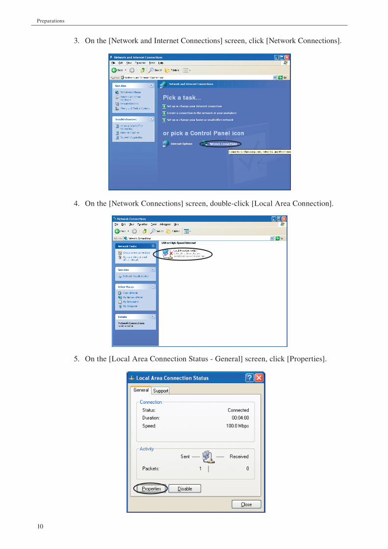
3. On the [Network and Internet Connections] screen, click [Network Connections].
4. On the [Network Connections] screen, double-click [Local Area Connection].
5. On the [Local Area Connection Status - General] screen, click [Properties].

11
Preparations
6. On the [Local Area Connection Properties - General] screen, select the [Internet
Protocol (TCP/IP) check box and double-click.
7. On the [Internet Protocol (TCP/IP) Properties - General] screen, select the [Use
the following IP address] check box and enter the IP address in the IP address
fi eld.
In the Subnet Mask fi eld, enter “255 . 255 . 255 . 0”.
Leave the Default Gateway fi eld blank.
When the input is complete, click [OK].

12
Preparations
Setup procedure when using Windows Vista
1. Click the Windows symbol in the bottom left corner of the screen and select [Con-
trol Panel] from the start menu that appears.
2. On the [Control Panel] screen, click [Network and Internet].

13
Preparations
3. On the [Network and Internet] screen, click [Network and Sharing Center].
4. On the [Network and Sharing Center] screen, click [View Status] under [Local
Area Connection].
5. On the [Local Area Connection Status - General] screen, click [Properties].

14
Preparations
6. On the [Local Area Connection Properties - Networking] screen, select the [In-
ternet Protocol Version 4 (TCP/IPv4)] check box and double-click.
7. On the [Internet Protocol Version 4 (TCP/IPv4) Properties - General] screen, select
the [Use the following IP address] check box and enter the IP address in the IP
address fi eld.
In the Subnet Mask fi eld, enter “255 . 255 . 255 . 0”.
Leave the Default Gateway fi eld blank.
When the input is complete, click [OK].

15
Preparations
Installation
- The SA-02A4 can be installed either horizontally or vertically.
- The SA-02M is designed to be installed horizontally only. Do not block the ven-
tilation openings on the top by placing any objects on the unit.
Do not insert any objects between the bottom of the unit and the installation surface,
so that the ventilation openings on the bottom are also unobstructed.
Power supply connections
The SA-02M/SA-02A4 are to be powered from the supplied AC adapter (NC-99).
Important Do not use any AC adapter other than the supplied product. Otherwise overheating and damage may occur.
Make the connection as follows:
1. Insert the DC plug of the AC adapter into the DC input jack on the rear panel of
the unit.
2. Connect the power cord to the AC adapter.
3. Plug the power cord into a 100 V to 240 V AC outlet.
DIRECT INDIRECT INDIRECT INDIRECT IN
1
2
3
4
5
6
7
8
9
10
11
12
13
14
15
16
TRIG IN
INIT
TACHO IN
SYNC
ID
DC 12V5A
AL OUT
NIT
TACHO IN
DC-12V3A
AC adapter NC-99
SA-02Mrear panel
SA-02A4rear panel
DC plug
DC input jack
DC input jack
Power cord
100 V to 240 VAC outlet

16
Preparations
WARNING Do not insert or disconnect the power cord plug with wet hands, to prevent the risk of electric shock.
Do not plug the power cord into a power strip along with other electrical devices, to prevent the risk of overheating and fi re. Always plug the power cord directly into a wall outlet (100 V to 240 V AC).
When handling the power cord plug, observe the following precautions, to prevent the risk of fi re:
- Make sure that the plug is clean before inserting it.
- Always fully insert the plug and make sure that is properly seated.
Do not cover the AC adapter with paper, cloth, or other objects, to prevent heat buildup and the risk of fi re.
Caution When using the AC adapter, do not coil or bunch the power cord.

17
Preparations
Connection to the computer
All communication between the SA-02M/SA-02A4 and the computer on which the dedi-
cated software (SA-02 BASE) is installed occurs via an Ethernet link. This includes setup
commands and data request commands sent to the SA-02M/SA-02A4, and response data
and measurement data sent from the SA-02M/SA-02A4.
Note
For details on how to install the dedicated software on the com-puter, please refer to the software instruction manual.
Procedure
1. Connect the LAN connector of the SA-02M/SA-02A4 to the LAN connector of
the computer, using the supplied 3 m LAN cable (cross-wired).
SA-02M/SA-02A4
Computer(generic)
Response, data transfer
Setup, data request
Ethernet
DIRECT INDIRECT INDIRECT INDIRECT IN
1
2
3
4
5
6
7
8
9
10
11
12
13
14
15
16
TRIG IN
INIT
TACHO IN
SYNC
ID
DC 12V5A
DIRECT INSIGNAL OUT
TRIG IN INIT
TACHO IN
DC-12V3A
12
To LAN connector on computer
LAN cable (supplied, 3 m)
SA-02A4rear panel SA-02M
rear panel
LAN connector
LAN connector

18
Preparations
Important
Do not disconnect the LAN cable while the dedicated software is running.
If the LAN cable was disconnected by mistake, power to the SA-02M/SA-02A4 needs to be turned off and then on again. The dedicated software also should be shut down and restarted.
If other devices are also connected to the computer at the same time, correct operation of the SA-02M/SA-02A4 is not assured.
Note
Use the supplied LAN cable for the connection.
For information about using other LAN cables, contact the sup-plier.
Power-on
To turn the SA-02M/SA-02A4 on, press the upper part ( | ) of the POWER switch. After
the power is turned on, the POWER switch lamp fl ashes for about 15 seconds. During this
interval, the SA-02M/SA-02A4 will not be accessible from the computer, and you should
not attempt to access it.
When the POWER switch stops fl ashing and stays constantly lit, the SA-02M/SA-02A4
can be accessed from the computer.
Important Do not turn the SA-02M/SA-02A4 off during the POWER switch lamp fl ashes. Otherwise there is a risk of damage to the SA-02M/SA-02A4.
Before turning on the SA-02M, verify that the unit ID switch is set to “0”. If the setting is not “0”, turn the unit off, set the switch to “0”, and then turn the unit on again.
Power-off
To turn the SA-02M/SA-02A4 off, press the lower part ( ) of the POWER switch. The
POWER switch lamp goes out.
Caution While the unit is not being used, you should disconnect the power cord from the AC outlet for safety.
19
Preparations
Setting the IP address of the SA-02M/SA-02A4
Perform the following steps to set the IP address of the SA-02M/SA-02A4. This procedure
requires that the Target Management Utility software is installed on the computer con-
nected to the SA-02M/SA-02A4 (see software instruction manual).
1. Turn power to the SA-02M/SA-02A4 on.
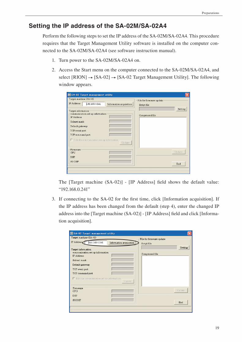
2. Access the Start menu on the computer connected to the SA-02M/SA-02A4, and
select [RION] [SA-02] [SA-02 Target Management Utility]. The following
window appears.
The [Target machine (SA-02)] - [IP Address] fi eld shows the default value:
“192.168.0.241”
3. If connecting to the SA-02 for the fi rst time, click [Information acquisition]. If
the IP address has been changed from the default (step 4), enter the changed IP
address into the [Target machine (SA-02)] - [IP Address] fi eld and click [Informa-
tion acquisition].
20
Preparations
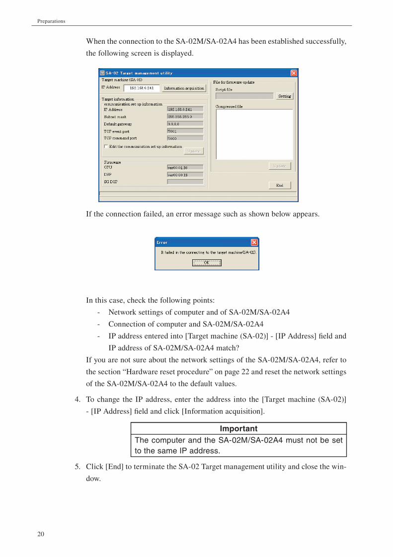
When the connection to the SA-02M/SA-02A4 has been established successfully,
the following screen is displayed.
If the connection failed, an error message such as shown below appears.
In this case, check the following points:
- Network settings of computer and of SA-02M/SA-02A4
- Connection of computer and SA-02M/SA-02A4
- IP address entered into [Target machine (SA-02)] - [IP Address] fi eld and
IP address of SA-02M/SA-02A4 match?
If you are not sure about the network settings of the SA-02M/SA-02A4, refer to
the section “Hardware reset procedure” on page 22 and reset the network settings
of the SA-02M/SA-02A4 to the default values.
4. To change the IP address, enter the address into the [Target machine (SA-02)]
- [IP Address] fi eld and click [Information acquisition].
Important The computer and the SA-02M/SA-02A4 must not be set to the same IP address.
5. Click [End] to terminate the SA-02 Target management utility and close the win-
dow.
21
Preparations
Screen explanation
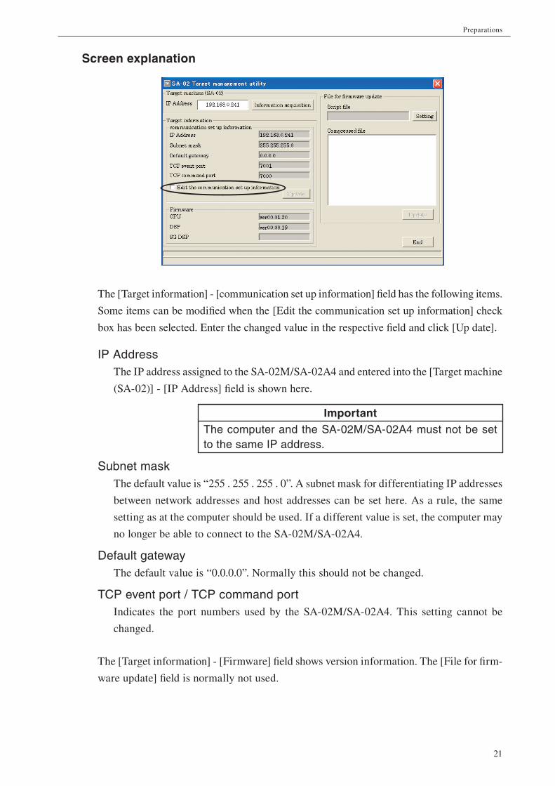
The [Target information] - [communication set up information] fi eld has the following items.
Some items can be modifi ed when the [Edit the communication set up information] check
box has been selected. Enter the changed value in the respective fi eld and click [Up date].
IP Address The IP address assigned to the SA-02M/SA-02A4 and entered into the [Target machine
(SA-02)] - [IP Address] fi eld is shown here.
Important The computer and the SA-02M/SA-02A4 must not be set to the same IP address.
Subnet mask The default value is “255 . 255 . 255 . 0”. A subnet mask for differentiating IP addresses
between network addresses and host addresses can be set here. As a rule, the same
setting as at the computer should be used. If a different value is set, the computer may
no longer be able to connect to the SA-02M/SA-02A4.
Default gateway The default value is “0.0.0.0”. Normally this should not be changed.
TCP event port / TCP command portIndicates the port numbers used by the SA-02M/SA-02A4. This setting cannot be
changed.
The [Target information] - [Firmware] fi eld shows version information. The [File for fi rm-
ware update] fi eld is normally not used.

22
Preparations
Hardware reset procedure Pressing the LAN setup initialize switch returns the network settings of the SA-02M/SA-
02A4 to the default condition. Perform the hardware reset as follows.
1. Verify that the POWER switch of the SA-02M/SA-02A4 is OFF.
2. Use the tip of a stylus or a similar tool to push down the LAN setup initialize switch
(INT) on the rear panel of the SA-02M/SA-02A4. Do not use a sharp metallic
object such as wire or a cutter knife to avoid the risk of damaging the switch.
3. While holding down the LAN setup initialize switch, turn power to the unit on.
You can release the switch when the POWER switch has started to fl ash.
4. When the POWER switch stops fl ashing and stays constantly lit, the initialization
is complete.

23
Preparations
Connecting the copy protection key
To be able to use the dedicated software installed on the computer, the copy protection
key supplied with the software must be connected to the computer.
Note
If the copy protection key is not connected, the software will not start up.
Keep the copy protection key in a safe location. If it is lost or has become damaged, the software cannot be used.
Procedure
Plug the copy protection key into a USB port on the computer.

24
Preparations
Using two SA-02M units together
To use two SA-02M units together, the units are synchronized via a LAN cable and con-
nected to the computer via a switching hub. The Connecting kit available as an option
comprises the LAN cables and hub.
Connecting the SA-02M units Use the 0.5 m LAN cable (straight cable) supplied with the optional Connecting kit to
connect the unit sync connectors on the rear panels of the two SA-02M units.
After connecting the LAN cable, set the Unit ID switches. On the unit using channels for
1 to 16, set the Unit ID switch to “1”, and set the switch to “2” on the unit using channels
for 17 to 32.
Note
Use only the LAN cables supplied as part of the optional Con-necting kit.
DIRECT INDIRECT INDIRECT INDIRECT IN
1
2
3
4
5
6
7
8
9
10
11
12
13
14
15
16
TRIG IN
INIT
TACHO IN
SYNC
ID
DC 12V5A
DIRECT IN
1
2
3
4
TRIG IN
INIT
TACHO IN
SYNC
ID
DC 12V5A
SA-02M rear panelSA-02M rear panel
Unit sync connector Unit sync connector
Unit IDswitches
LAN cable 0.5 m(Connecting kit, option)

25
Preparations
Connection to the Computer The two SA-02M units must be connected to the computer via the switching hub supplied
as part of the optional Connecting kit. Use the 3 m LAN cables (straight cables) supplied
with the kit.
Note
Use only the switching hub and LAN cables supplied as part of the optional Connecting kit.
For details on using the switching hub, please refer to the supplied documentation.
Link/Act
PWR
1000/100/10M
12345
DIRECT INDIRECT INDIRECT INDIRECT IN
1
2
3
4
5
6
7
8
9
10
11
12
13
14
15
16
TRIG IN
INIT
TACHO IN
SYNC
ID
DC 12V5A
DIRECT IN
1
2
3
4
TRIG IN
INIT
TACHO IN
SYNC
ID
DC 12V5A
To LAN connector on computer
SA-02M rear panelSA-02M rear panel
Switching hub(Connecting kit, option)
LAN cable 3 m(Connecting kit, option)
LANconnector

26
Signal input/output
Signal input via BNC input connectors
The BNC input connectors accept the AC output supplied by a sound or vibration level
meter, as well other kinds of electrical signals. An accelerometer with integrated pream-
plifi er can also be connected.
WARNING Do not touch the BNC input connectors with a wire, pin, or similar object, to prevent the risk of electric shock.
Important Make signal input connections from a source device only while power to the SA-02M/SA-02A4 is turned off, to prevent the risk of damage.
Connection example 1 Connecting the AC output of a sound level meter
By connecting the AC output of a sound level meter (NL series, NA series or other product,
option) to the BNC input connector, using the BNC - mini plug cable CC-24S (option),
the signal captured by the microphone of the sound level meter can be supplied to the
SA-02M/SA-02A4.
SA-02M rear panel
SA-02A4 rear panel
DIRECT INDIRECT INDIRECT INDIRECT IN
1
2
3
4
5
6
7
8
9
10
11
12
13
14
15
16
TRIG IN
INIT
TACHO IN
SYNC
ID
DC 12V5A
DIRECT INSIGNAL OUT
TRIG IN INIT
TACHO IN
DC-12V3A
1234
123
BNC - mini plug cable CC-24SCC-24 can also be used
Sound level meter(NL, NA series)
To AC OUT

27
Signal input/output
Connection example 2 Connecting a constant current drive preamplifi er
A microphone (such as the UC-52, UC-53A etc., option) mounted on a constant current drive
type microphone preamplifi er (such as the NH-22, NH-22T etc., option) can be connected,
using a cable of the BNC - BNC coaxial cable EC-90 series (option), as shown below.
Connection example 3 Connecting an accelerometer with integrated preamplifi er
A piezoelectric accelerometer with integrated preamplifi er (such as the PV-41, PV-90I etc.,
option) can be connected, using an accelerometer cable of the VP-51 series or the cable
supplied with the accelerometer and the BNC adapter VP-52C (option), as shown below.
SA-02M rear panel
SA-02A4 rear panel
BNC - BNC coaxial cableEC-90 series
Microphone preamplifierNH-22, NH-22T etc.
MicrophoneUC-52, UC-53A etc.
DIRECT INDIRECT INDIRECT INDIRECT IN
1
2
3
4
5
6
7
8
9
10
11
12
13
14
15
16
TRIG IN
INIT
TACHO IN
SYNC
ID
DC 12V5A
DIRECT INSIGNAL OUT
TRIG IN INIT
TACHO IN
DC-12V3A
1234
123
VP-52CBNC adapter
SA-02M rear panel
SA-02A4 rear panel
PV-41, PV-90I etc.
Accelerometer cable VP-51 series orcable supplied with accelerometer
DIRECT INDIRECT INDIRECT INDIRECT IN
1
2
3
4
5
6
7
8
9
10
11
12
13
14
15
16
TRIG IN
INIT
TACHO IN
SYNC
ID
DC 12V5A
DIRECT INSIGNAL OUT
TRIG IN INIT
TACHO IN
DC-12V3A
1234
123

28
Signal input/output
Connection example 4 Connecting a charge converter
A piezoelectric accelerometer (PV-85, PV-90B etc., option) used together with the charge
converter VP-40 (option) can be connected, as shown below.
Signal output
The signal in each channel can be output as an AC signal.
Note
The signal supplied at the AC output connectors is obtained by applying frequency weighting to each channel input signal and adjusting the level so that 1 Vrms corresponds to the full-scale point in the selected level range.
The AC output connectors for slots in which no unit is installed are inactive.
Example: Using a level recorder The level waveform for each channel can be recorded by connecting a level recorder (LR series,
option) to the unit, using the BNC - mini plug cable CC-24S (option), as shown below.
SA-02M rear panel
SA-02A4 rear panel
VP-40 90001RION
Charge converterVP-40
Accelerometer cableVP-51 series
Piezoelectricaccelerometer
PV-85, PV-90B, etc.
DIRECT INDIRECT INDIRECT INDIRECT IN
1
2
3
4
5
6
7
8
9
10
11
12
13
14
15
16
TRIG IN
INIT
TACHO IN
SYNC
ID
DC 12V5A
DIRECT INSIGNAL OUT
TRIG IN INIT
TACHO IN
DC-12V3A
1234
123
Dual Channel
Level Recorder LR-20
CH A CH BMarker
Input
DC
AC
LIN
LOG
Zero ADJ
Scale
Level ADJ
FastSlowVL
0 10
Channel A
Channel A Mode
A
A-B (LOG Scale)
Power Maker Light
ON
OFF
(Charge)
Input
DC
AC
LIN
LOG
Zero ADJ
Scale
Level ADJ
FastSlowVL
0 10
Channel B
Paper Speed mm s
Pen Paper
CH A
ON
30
10
310.3
0.1
0.03
0.01
EXT
CH B
ON ON
STOP STOP REV STOP
SA-02M front panel
SA-02A4 front panel
BNC - mini plug cable CC-24S
To INPUT
Level recorder(LR series)
SA-02MSIGNAL ANALYZER
4
1
2
3
5
6
7
8 12
11
10
9
16
15
14
13
AC OUT
SA-02A4SIGNAL ANALYZER
1
AC OUT
2 3 4

29
External trigger signal input
If a trigger pulse generator is connected to the trigger input connector (TRIG IN), the unit
can be controlled by a trigger. As shown in the illustration below, triggering occurs when
the trigger signal stays at LOW level for at least 1 ms.
Connection exampleConnecting a trigger pulse generator
The BNC - mini plug cable CC-24S (option) can be used to connect a trigger pulse genera-
tor equipped with a BNC output, as shown below.
1 ms
Pulse width 1 ms or more
TTL levelHIGH level
LOW level
Processing
Time
To signal output oftrigger pulse generator
DIRECT INDIRECT INDIRECT INDIRECT IN
1
2
3
4
5
6
7
8
9
10
11
12
13
14
15
16
TRIG IN
INIT
TACHO IN
SYNC
ID
DC 12V5A
DIRECT INSIGNAL OUT
TRIG IN INIT
TACHO IN
DC-12V3A
DIRECT INSIGNAL OUT
TRIG IN INIT
TACHO IN
DC-12V3A
SA-02A4 rear panel
SA-02M rear panel
123
To trigger input connector (TRIG IN)
BNC - mini plug cableCC-24S

30
Tachometer signal input
The rotary pulse input connector (TACHO IN) serves for input of a rotary pulse signal
(Tacho signal). The SA-02M/SA-02A4 can perform tracking analysis of a pulse signal
derived from a rotating object such as a fan or motor and changing with the revolution
speed.
The rotary pulse signal can also be used for triggering.
Connection exampleConnecting a rotary pulse generator
The BNC - BNC coaxial cable EC-90 series (option) can be used to connect a rotary pulse
generator equipped with a BNC output, as shown below.
To rotary pulse input connector (TACHO IN)
To signal output of photoelectronic pulse generatoror other device generating a signal controlledby the revolution speed of a rotating object
DIRECT INDIRECT INDIRECT INDIRECT IN
1
2
3
4
5
6
7
8
9
10
11
12
13
14
15
16
TRIG IN
INIT
TACHO IN
SYNC
ID
DC 12V5A
SIGNAL OUT
TRIG IN INIT
TACHO IN
DC-12V3A
SIGNAL OUT
TRIG IN INIT
TACHO IN
DC-12V3A
SA-02A4 rear panel
SA-02M rear panel
BNC - BNC coaxial cableEC-90 series
31
Specifi cations
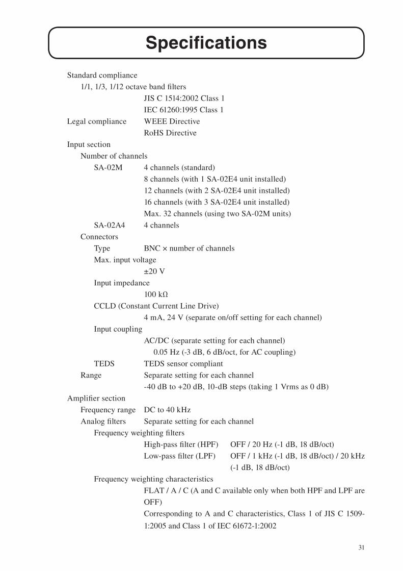
Standard compliance
1/1, 1/3, 1/12 octave band fi lters
JIS C 1514:2002 Class 1
IEC 61260:1995 Class 1
Legal compliance WEEE Directive
RoHS Directive
Input section
Number of channels
SA-02M 4 channels (standard)
8 channels (with 1 SA-02E4 unit installed)
12 channels (with 2 SA-02E4 unit installed)
16 channels (with 3 SA-02E4 unit installed)
Max. 32 channels (using two SA-02M units)
SA-02A4 4 channels
Connectors
Type BNC × number of channels
Max. input voltage
±20 V
Input impedance
100 kΩ
CCLD (Constant Current Line Drive)
4 mA, 24 V (separate on/off setting for each channel)
Input coupling
AC/DC (separate setting for each channel)
0.05 Hz (-3 dB, 6 dB/oct, for AC coupling)
TEDS TEDS sensor compliant
Range Separate setting for each channel
-40 dB to +20 dB, 10-dB steps (taking 1 Vrms as 0 dB)
Amplifi er section
Frequency range DC to 40 kHz
Analog fi lters Separate setting for each channel
Frequency weighting fi lters
High-pass fi lter (HPF) OFF / 20 Hz (-1 dB, 18 dB/oct)
Low-pass fi lter (LPF) OFF / 1 kHz (-1 dB, 18 dB/oct) / 20 kHz
(-1 dB, 18 dB/oct)
Frequency weighting characteristics
FLAT / A / C (A and C available only when both HPF and LPF are
OFF)
Corresponding to A and C characteristics, Class 1 of JIS C 1509-
1:2005 and Class 1 of IEC 61672-1:2002

32
Specifi cations
Inherent noise -85 dB or less of range full-scale (all-pass level, 0 dB range)
-65 dB or less of range full-scale (all-pass level, -40 dB range)
Dynamic range 105 dB or more (0 dB range)
Crosstalk -105 dB or less (1/3 octave, 0 dB range, 1 kHz band)
Overload level +2 dB of range full-scale
A/D converter section
A/D converter Simultaneous sampling of all channels
24-bit delta-sigma type converter
Sampling frequency 102.4 kHz
Input/output section
AC output connectors
Type 2.5 dia. mono phone jack × number of channels
Output impedance
600 Ω
Output voltage
1 Vrms (at input range full-scale point)
Output signal Routed through analog fi lter before output
Trigger input connector
Type 2.5 dia. mono phone jack × 1
Input signal Open collector supported
5 V input, TTL level threshold
Rotary pulse input connector
Type BNC × 1
Input signal Rotary pulse, 0 to 10 V
Input impedance
100 kΩ
H-L threshold 1 to 4 V, changeable in 0.1-V steps
Pulse measurement method
Cycle measurement with 12.5 MHz sampling
Measurement range
30 to 600,000 pulses/minute
Data save cycle
Time waveform transfer mode:
sampling frequency of A/D converter
Octave mode: every 100 ms
LAN connector RJ-45 × 1, 100 Base-TX
Unit sync connector (SA-02M only)
RJ-45 × 1
Sync cable length: max. 50 cm

33
Specifi cations
Display section
Number of windows
2 / 4 / 8 / 12 / 16 / 32
FFT analysis Functions calculated with FFT are shown (dependent on FFT analysis
functions)
Octave band analysis
1/1, 1/3, 1/12 octave band analysis results and processing results
are shown
Analysis processing section
Using sampling data obtained by digitizing the input signals, the
section handles calculation processing, store operations, trigger
processing, and command send/receive communication with the
computer
Recording section
File input/output
Test parameter fi le
Settings can be saved to and loaded from a fi le
Data fi le Analysis data can be saved to and loaded from a fi le in CSV for-
mat
JPEG fi le Graphs can be saved to a fi le in JPEG format
Copy function A specifi ed graph or the entire window can be copied to the clip-
board
FFT analyzer section
Analysis frequencies (Hz)
40 k, 20 k, 10 k, 5 k, 2 k, 1 k, 500, 200, 100
Number of analysis points
64, 128, 256, 512, 1024, 2048, 4096, 8192, 16384, 32768
Throughput performance
20 kHz, 16 channels
Trigger processing
Trigger modes
Free, Single, Repeat
Trigger types Level trigger, external trigger, signal output trigger, rotary pulse
trigger
Trigger position
Settable in 1-sample steps over ±1 frame range

34
Specifi cations
Level trigger conditions
Trigger channel: Channel used for trigger detection
Trigger amplitude: Input signal amplitude used for trigger
detection
Slope: Amplitude change direction used for trig-
ger detection
+ (Trigger amplitude down up
change)
- (Trigger amplitude up down
change)
Rotary pulse trigger conditions
Trigger rotary pulse: rpm used for trigger detection (number of
pulses per minute)
Slope: Speed change direction used for trigger
detection
+ (Trigger rotary pulse low high
change)
- (Trigger rotary pulse high low
change)
Phase difference
Corresponding to Processor Class 1 of the JIS C 1507:2006 and IEC
61043:1993 (among channels in same slot)
Within ±1 degree at 40 kHz
Inherent noise
-105 dB or lower (40 kHz range, 0 dB range, 1024 analysis points)
Octave band analyzer section
Analysis types 1/1, 1/3, 1/12 octave band analysis
Standard compliance
JIS C 1514 (IEC 61260) Class 1
Analysis bandwidth, number of channels, analysis frequency range, number of bands
1/1: 0.5 Hz to 16 kHz octave center frequencies and AP,
17 bands
1/3: 0.4 Hz to 20 kHz 1/3 octave center frequencies and
AP, 49 bands
1/12 (1 channel per board)
0.36 Hz to 22 kHz 1/12 octave center frequencies and
AP, 193 bands
1/12 (2 channels per board)
0.36 Hz to 11 kHz 1/12 octave center frequencies and
AP, 181 bands

35
Specifi cations
1/12 (4 channels per board)
0.36 Hz to 5.5 kHz 1/12 octave center frequencies and
AP, 169 bands
Operating channels in 1/12 mode are determined by the number of chan-
nels per board. The combination of channel number setting per board
and number of operating channels is shown in the table below.
Number of channels per board
1st 2nd 3rd 4th 5th 6th 7th 8th
1 1 5 9 13 17 21 25 29
1 2 6 10 14 18 22 26 30
1 3 7 11 15 19 23 27 31
1 4 8 12 16 20 24 28 32
2 1, 3 5, 7 9, 11 13, 15 17, 19 21, 23 25, 27 29, 31
2 2, 4 6, 8 10, 12 14, 16 18, 20 22, 24 26, 28 30, 32
4 1 to 4 5 to 8 9 to 12 13 to 16 17 to 20 21 to 24 25 to 28 29 to 32
Time weighting characteristics (each channel)
1 ms, 10 ms, 35 ms, 125 ms (F), 630 ms (VL), 1 s (S), 10 s
Processing functions
Linear averaging
Processing time: 1 to 3600 s
direct calculation from fi lter output waveform
Maximum hold
Instantaneous value monitored and held for each sample
Maximum hold type
Band Maximum value monitored and held for each frequency
band
All-pass Maximum all-pass value monitored and values held
for all frequency bands
Memory functions
Store targets Instantaneous value, linear average value, or maximum value +
rotary pulse
Auto store function
Data are stored in internal memory at specifi ed store cycle and then
sent to computer
Store start/stop: Manual operation or trigger

36
Specifi cations
Store pause: Processing can be paused during storing
and resumed from same point
Store cycle: Instantaneous value
1 ms to 1000 ms (1-ms steps)
Number of store data: Min. 1, increments of 1, maximum number
dependent on analysis bandwidth
1/1: 36,000
1/3: 36,000
1/12: 18,000
Trigger processing
Trigger modes
Free, Single, Repeat
Trigger types Level trigger, external trigger, signal output trigger, rotary pulse
trigger
Trigger position
Settable in 1-s steps over 0 to 60 s range
Level trigger conditions
Trigger channel: Channel used for trigger detection
Trigger level: Input signal level used for trigger detec-
tion
0 to -80 dB of full scale, 1-dB steps
Slope: Level change direction used for trigger
detection
+ (Trigger level low high change)
- (Trigger level high low change)
Frequency band: Frequency band used for trigger detec-
tion
(For 1/12 octave band, 1/3 octave band is
used; triggering occurs when one of the
four 1/12 octave bands in one 1/3 octave
band is exceeded.)
Rotary pulse trigger conditions
Trigger rotary pulse: rpm used for trigger detection (number of
pulses per minute)
Slope: Speed change direction used for trigger
detection
+ (Trigger rotary pulse low high
change)
- (Trigger rotary pulse high low
change)
Trigger controlled operation
Processing (linear average / maximum hold) start, auto store start

37
Specifi cations
Inherent noise levels
At 0 dB level range
All-pass: -85 dB of range full-scale
1/1 octave band: -93 dB of range full-scale
1/3 octave band: -97 dB of range full-scale
1/12 octave band: -102 dB of range full-scale
At -40 dB level range
All-pass: -65 dB of range full-scale
1/1 octave band: -70 dB of range full-scale
1/3 octave band: -77 dB of range full-scale
1/12 octave band: -82 dB of range full-scale
Time waveform + octave analysis simultaneous processing
Time waveform and octave analysis results can be sent to computer
simultaneously
Repeat trigger and trigger position cannot be used
Switches
POWER switch Rocker switch with LED illumination
LAN setup initialize switch
Push switch × 1
Unit ID switch Rotary switch × 1 (SA-02M only)
LEDs Overload indication for each channel
Lit green: No overload has occurred
Lit red: Overload has occurred
LEDs for unused channels are off
Optional expansion
Channel expansion slots
SA-02A4: None
SA-02M: 3
Signal output units installed
SA-02A4: 1
SA-02M: 1
Ambient conditions for use
0°C to +40°C, max. 90% RH (no condensation)
Power supply
Source AC adapter NC-99
Power consumption (no option unit installed, NC-99 used at 100 V to 240 V AC)
SA-02A4: approx. 30 VA
SA-02M (4 channels installed): approx. 30 VA
SA-02M (8 channels installed): approx. 40 VA
SA-02M (12 channels installed): approx. 50 VA
SA-02M (16 channels installed): approx. 60 VA

38
Specifi cations
Dimensions and weight
SA-02A4 58 (H) mm × 260 (W) mm × 210 (D) mm
(without protruding parts and rubber feet)
Approx. 2.5 kg
SA-02M 151 (H) mm × 290 (W) mm × 249 (D) mm
(without protruding parts and rubber feet)
Approx. 5.4 kg (4 channels installed)
Approx. 5.9 kg (8 channels installed)
Approx. 6.3 kg (12 channels installed)
Approx. 6.8 kg (16 channels installed)
Supplied accessories
AC adapter NC-99 1
LAN cable (STP, cross-wired, 3 m) 1
Hardware instruction manual 1
Software instruction manual 1
Inspection certifi cate 1
Options
4-channel input unit SA-02E4
Signal output unit SA-02SG
Airborne noise/fl oor impact noise insulation measurement software
AS-20PE5
Semi-anechoic acoustic power level measurement software AS-30PA5
Acoustic intensity measurement software AS-15PA5
Connecting kit
LAN cable (STP, straight, 3 m) 3
LAN cable (STP, straight, 0.5 m, for unit sync connection) 1
Switching hub 1

39
Specifi cations
Typical characteristics of fi lter
Typical characteristic of low-pass fi lter (LPF: 1 kHz, 20 kHz)
Typical characteristic of high-pass fi lter (HPF: 20 Hz)
1 kHz LPF 20 kHz LPF
20 Hz HPF
Frequency (Hz)
Frequency (Hz)
Gai
n (d
B)
Gai
n (d
B)

40
Specifi cations
Unit: mm
SA-02M Dimensional Drawings
SA-02MSIGNAL ANALYZER
4
1
2
3
5
6
7
8 12
11
10
9
16
15
14
13
AC OUT
DIRECT INDIRECT INDIRECT INDIRECT IN
1
2
3
4
5
6
7
8
9
10
11
12
13
14
15
16
TRIG IN
INIT
TACHO IN
SYNC
ID
DC 12V5A
290
151
249
265
165
310
Right side view Top view
Front view
Rear view
41
Specifi cations
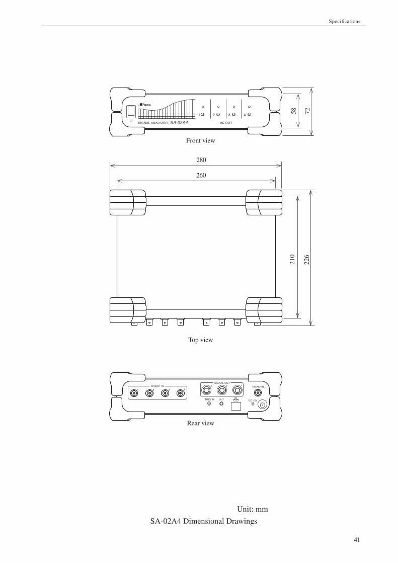
Unit: mm
SA-02A4 Dimensional Drawings
210
SA-02A4SIGNAL ANALYZER
1
AC OUT
2 3 4
DIRECT INSIGNAL OUT
TRIG IN INIT
TACHO IN
DC-12V3A
260
58 7222
6
280
1234
123
Top view
Front view
Rear view

No. 51801 13-05