MULTI-BODY DYNAMIC ANALYSIS OF AN IC ENGINE ... Int. J. Mech. Eng. & Rob. Res. 2014 Shivayogi S...
5
67 MULTI-BODY DYNAMIC ANALYSIS OF AN IC ENGINE PISTON FOR SHAPE OPTIMIZATION Shivayogi S Hiremath 1 * and I G Bhavi 1 *Corresponding Author: Shivayogi S Hiremath [email protected] Piston in an internal combustion engine is subjected to gas force. In internal combustion engine, piston is one of the important components parts defined as cylindrical components that moves up and down in the cylinder bore by force produce during the combustion process. The features of the piston are piston head, piston pin bore, piston pin, skirt, ring groove, ring land and piston ring. In this work the connecting rod of a Kirloskar TV1 diesel engine producing a rated output of 5.2Kw at 1500rpm is considered for the study. Load curves are obtained from the pressure - crank angle plots. Gas forces and inertia forces are calculated from these curves. Finite element analysis software ANSYS13 is used to study the stress distribution and deformation in the Piston. The dimensions are physically measured to obtain the CAD model of connecting rod in CATIA V5. Since the weight of the piston has considerable influence on its dynamic behavior, an optimization study was performed on a Aluminum forged piston with a consideration for reduction in weight, stress Keywords: Piston, FEA, Weight optimization, MBD INTRODUCTION In an engine purpose of piston is to transfer force from expanding gas in the cylinder to the crankshaft via a piston rod or connecting rod. The piston primarily subjected to gas forces directly. So piston has to be designed to withstand these direct gas pressure conditions. As an important part in an engine, piston endures the cyclic gas pressure and the inertial Int. J. Mech. Eng. & Rob. Res. 2014 1 Department of Mechanical Engineering, BLDEA’s College of Engineering & Technology, Bijapur, Karnataka, India. forces at work, and this working condition may cause the fatigue damage of piston, such as piston side wear, piston head/crown cracks and so on. It also has to withstand the load because of gas pressure generated during compression stroke of the engine cycle. Therefore for efficient design it is inevitable to analyze the stresses induced in the piston using FEM technique or some other advanced technical design. Research Paper ISSN 2278 – 0149 www.ijmerr.com Vol. 3, No. 4, October 2014 © 2014 IJMERR. All Rights Reserved
Transcript of MULTI-BODY DYNAMIC ANALYSIS OF AN IC ENGINE ... Int. J. Mech. Eng. & Rob. Res. 2014 Shivayogi S...

67
Int. J. Mech. Eng. & Rob. Res. 2014 Shivayogi S Hiremath and I G Bhavi, 2014
MULTI-BODY DYNAMIC ANALYSIS OF AN ICENGINE PISTON FOR SHAPE OPTIMIZATION
Shivayogi S Hiremath1* and I G Bhavi1
*Corresponding Author: Shivayogi S Hiremath [email protected]
Piston in an internal combustion engine is subjected to gas force. In internal combustion engine,piston is one of the important components parts defined as cylindrical components that movesup and down in the cylinder bore by force produce during the combustion process. The featuresof the piston are piston head, piston pin bore, piston pin, skirt, ring groove, ring land and pistonring. In this work the connecting rod of a Kirloskar TV1 diesel engine producing a rated output of5.2Kw at 1500rpm is considered for the study. Load curves are obtained from the pressure -crank angle plots. Gas forces and inertia forces are calculated from these curves. Finite elementanalysis software ANSYS13 is used to study the stress distribution and deformation in the Piston.The dimensions are physically measured to obtain the CAD model of connecting rod in CATIAV5. Since the weight of the piston has considerable influence on its dynamic behavior, anoptimization study was performed on a Aluminum forged piston with a consideration for reductionin weight, stress
Keywords: Piston, FEA, Weight optimization, MBD
INTRODUCTIONIn an engine purpose of piston is to transferforce from expanding gas in the cylinder to thecrankshaft via a piston rod or connecting rod.The piston primarily subjected to gas forcesdirectly. So piston has to be designed towithstand these direct gas pressureconditions.
As an important part in an engine, pistonendures the cyclic gas pressure and the inertial
Int. J. Mech. Eng. & Rob. Res. 2014
1 Department of Mechanical Engineering, BLDEA’s College of Engineering & Technology, Bijapur, Karnataka, India.
forces at work, and this working condition maycause the fatigue damage of piston, such aspiston side wear, piston head/crown cracksand so on. It also has to withstand the loadbecause of gas pressure generated duringcompression stroke of the engine cycle.
Therefore for efficient design it is inevitableto analyze the stresses induced in the pistonusing FEM technique or some other advancedtechnical design.
Research Paper
ISSN 2278 – 0149 www.ijmerr.comVol. 3, No. 4, October 2014
© 2014 IJMERR. All Rights Reserved
68
Int. J. Mech. Eng. & Rob. Res. 2014 Shivayogi S Hiremath and I G Bhavi, 2014
INTERNAL COMBUSTIONENGINESEngine Parts
The essential parts of automobile engine areas follows: cylinder block, cylinder head, crankcase, piston, piston rings, piston pin,connecting rod, crank shaft, fly wheel, valvesand mechanism.
Piston
Piston is considered to be one of the mostimportant parts in a reciprocating engine inwhich it helps to convert the chemical energyobtained by the combustion of fuel into usefulmechanical power. The purpose of the pistonis to provide a means of conveying theexpansion of the gasses to the crankshaft, viathe connecting rod, without loss of gasfromabove or oil from below. Piston isessentially cylindrical plug that moves up anddown in the cylinder. It is equipped with pistonrings to provide a good seal between thecylindrical wall and piston.Although the pistonappears to be a simple part, it actually quitecomplex from the design point of view. Theefficiency and economy of the engine primarilydepends on the working of piston. It mustoperate in the cylinder with minimum of frictionand should be able to with stand the highexplosive force developed in the cylinder andalso the very high temperature ranging from2000 °C to over 2800 °C during operation. Thepiston should be as strong as possible,however its weight should be minimized as foras possible in order to reduce the inertiadue to its reciprocating mass .
Functions of Piston• To receive the thrust force generated by
explosion of the gas in the cylinder and
transmits it to the connecting rod.
• To reciprocate in the cylinder as a gas tightplug causing suction, compression,expansion and exhaust stroke.
• To form a guide and bearing to the smallend of the connecting rod and to take theside thrust due to the obliquity of the rod.
The top of the piston is called head ringgrooves are located at the top circumferenceportion of the piston. Portion below the ringgrooves is called skirt. The portion of the pistonthat separates the grooves is called the lands.Some pistons have a groove in the top landcalled a heat dam which reduces heat tothe rings. The piston bosses are Thosereinforced section of the piston designed tohold the piston pin.
Piston Materials
The material used for pistons is mainlyaluminium alloy. Aluminium pistons can beeither cast or forged. Cast iron is also usedfor pistons. In early years cast iron was almostuniversal material for pistons because itposses excellent wearing qualities, coefficientof expansion and general suitability inmanufacture. But due to the reduction of weightin reciprocating parts, the use of aluminium forpiston was essential. To obtain equal strengtha greater thickness of metal is necessary. Butsome of the advantage of the light metal is lost.Aluminium is inferior to cast iron in strengthand wearing qualities, and its greatercoefficient of expansion necessitates greaterclearance in the cylinder to avoid the risk ofseizure. the heat conductivity of aluminium isabout thrice that of cast iron and this combinedwith the greater thickness necessary forstrength, enables and aluminium alloy piston
69
Int. J. Mech. Eng. & Rob. Res. 2014 Shivayogi S Hiremath and I G Bhavi, 2014
to run at much lower temperature than a castiron one (200 °C to 250 °C as compared with400 °C to 450 °C) as a result carbonized oildoesn’t form on the underside of the piston,and the crank case therefore keeps cleaner.
This cool running property of aluminium isnow recognized as being quite as valuable asits lightness. Indeed; pistons are sometimesmade thicker than necessary for strength inorder to give improved cooling.
DESCRIPTION OF IC ENGINEMODELS FOR FINITE ELEMENTSTUDY
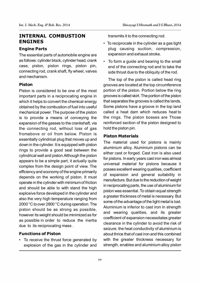
The Table 1 shows engine details.
All the dimensions and mass of connectingrod are obtained by physically measuring theconnecting rod at Bharat engineering works,Bijapur. Single cylinder Four Stroke DieselEngine (Test Rig).
Formulae
Gas force= Fg =A x P
S. No. Description Specification
1 Engine Type Kirlosker TV1
2 Cylinder Bore 87.5mm
3 Stroke 110mm
4 Engine rpm 1500rpm
5 Compression ratio 17.5:1
6 Rated Output 5.2Kw @ 1500rpm
7 Dynamometer Eddy current type
Table 1: Engine Specifications
Figure 1: Computerized IC Engine Setupto Obtain P- Diagram
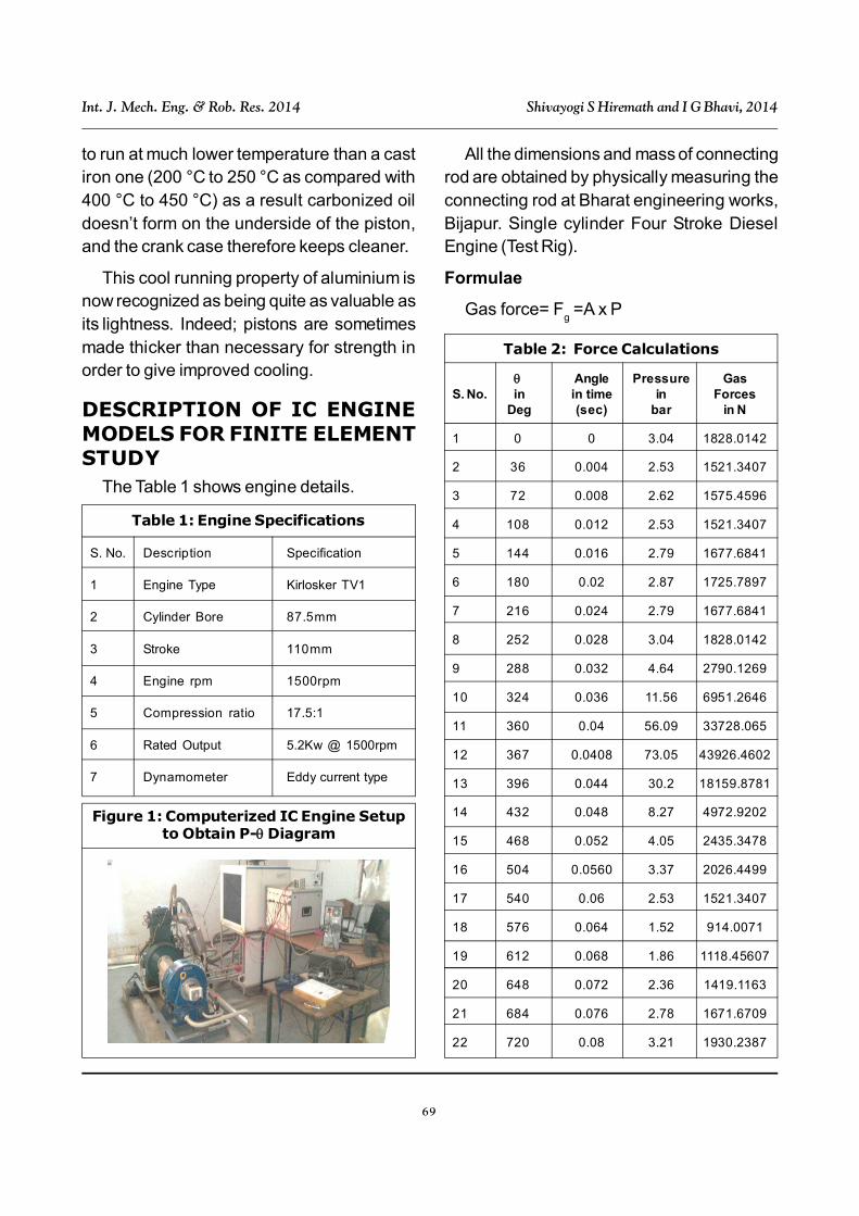
Table 2: Force Calculations
Angle Pressure GasS. No. in in time in Forces
Deg (sec) bar in N
1 0 0 3.04 1828.0142
2 36 0.004 2.53 1521.3407
3 72 0.008 2.62 1575.4596
4 108 0.012 2.53 1521.3407
5 144 0.016 2.79 1677.6841
6 180 0.02 2.87 1725.7897
7 216 0.024 2.79 1677.6841
8 252 0.028 3.04 1828.0142
9 288 0.032 4.64 2790.1269
10 324 0.036 11.56 6951.2646
11 360 0.04 56.09 33728.065
12 367 0.0408 73.05 43926.4602
13 396 0.044 30.2 18159.8781
14 432 0.048 8.27 4972.9202
15 468 0.052 4.05 2435.3478
16 504 0.0560 3.37 2026.4499
17 540 0.06 2.53 1521.3407
18 576 0.064 1.52 914.0071
19 612 0.068 1.86 1118.45607
20 648 0.072 2.36 1419.1163
21 684 0.076 2.78 1671.6709
22 720 0.08 3.21 1930.2387
70
Int. J. Mech. Eng. & Rob. Res. 2014 Shivayogi S Hiremath and I G Bhavi, 2014
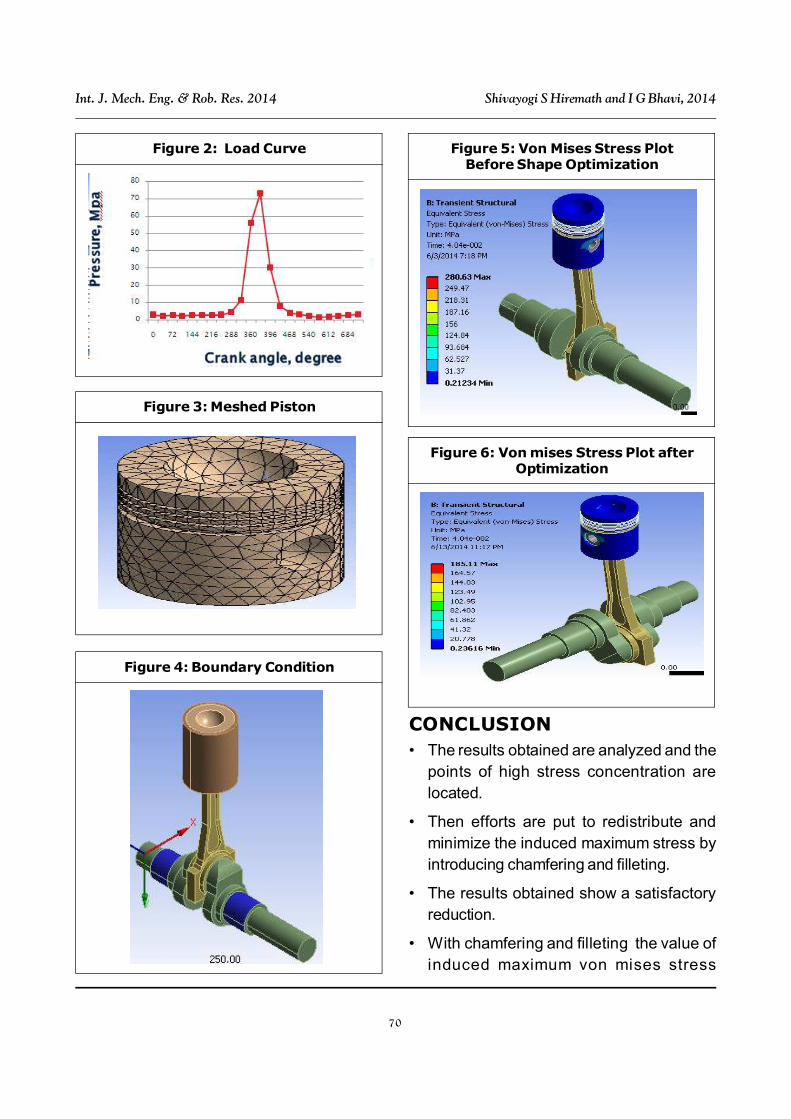
Figure 2: Load Curve
Figure 3: Meshed Piston
Figure 4: Boundary Condition
Figure 5: Von Mises Stress PlotBefore Shape Optimization
Figure 6: Von mises Stress Plot afterOptimization
CONCLUSION• The results obtained are analyzed and the
points of high stress concentration arelocated.
• Then efforts are put to redistribute andminimize the induced maximum stress byintroducing chamfering and filleting.
• The results obtained show a satisfactoryreduction.
• With chamfering and filleting the value ofinduced maximum von mises stress
71
Int. J. Mech. Eng. & Rob. Res. 2014 Shivayogi S Hiremath and I G Bhavi, 2014
reduced by 34.03% ,von mises strainreduced by 33.99%.
• Induced normal stress is reduced by 44.9%,and induced normal stress is reduced by37%.
• Weight is optimized by 0.16%.
REFERENCES1. Bhagat A R and Jibhakate Y M (2012),
“Thermal Analysis and Optimization of ICEngine Piston Using finite ElementMethod”, Vol. 2, No. 4.
2. Ghodake A P and Patil K “Piston Designand Analysis by CAE Tools”, ISSN: 2250-3021 ISBN: 2878-8719, pp. 33-36.
3. Praful R Sakharkar and Avinash M
Wankhade (2013), “Thermal Analysis Of
IC Engine Piston Using Fea”.
4. Venkata Rajam Ch. et al. (2013), “Design
Analysis and Optimization of Piston using
CATIA and ANSYS”, Vol. 1, No. 2.
5. Vivek zolekar (2013), “Finite Element
Analysis and Optimization of IC Engine
Piston Using RADIOSS and OptiStruct”.
6. Vinay V Kuppast and Kurbet S N, “Finite
Element And MBD Analysis of piston to
predict the Engine Noise”, ISSN 2278 –
0149.